

Page 1

SuperStack® 3
Webcache 1000 (3C16115)
Webcache 3000 (3C16116)
User Guide
http://www.3com.com/
Part No. DUA1611-5AAA02
Published May 2001
Page 2

3Com Corporation
5400 Bayfront Plaza
Santa Clara, California
95052-8145
Copyright © 2001, 3Com Technologies. All rights reserved. No part of this documentation may be reproduced
in any form or by any means or used to make any derivative work (such as translation, transformation, or
adaptation) without written permission from 3Com Technologies.
3Com Technologies reserves the right to revise this documentation and to make changes in content from time
to time without obligation on the part of 3Com Technologies to provide notification of such revision or
change.
3Com Technologies provides this documentation without warranty, term, or condition of any kind, either
implied or expressed, including, but not limited to, the implied warranties, terms or conditions of
merchantability, satisfactory quality, and fitness for a particular purpose. 3Com may make improvements or
changes in the product(s) and/or the program(s) described in this documentation at any time.
If there is any software on removable media described in this documentation, it is furnished under a license
agreement included with the product as a separate document, in the hard copy documentation, or on the
removable media in a directory file named LICENSE.TXT or !LICENSE.TXT. If you are unable to locate a copy,
please contact 3Com and a copy will be provided to you.
UNITED STATES GOVERNMENT LEGEND
If you are a United States government agency, then this documentation and the software described herein are
provided to you subject to the following:
All technical data and computer software are commercial in nature and developed solely at private expense.
Software is delivered as “Commercial Computer Software” as defined in DFARS 252.227-7014 (June 1995) or
as a “commercial item” as defined in FAR 2.101(a) and as such is provided with only such rights as are
provided in 3Com’s standard commercial license for the Software. Technical data is provided with limited rights
only as provided in DFAR 252.227-7015 (Nov 1995) or FAR 52.227-14 (June 1987), whichever is applicable.
You agree not to remove or deface any portion of any legend provided on any licensed program or
documentation contained in, or delivered to you in conjunction with, this User Guide.
Unless otherwise indicated, 3Com registered trademarks are registered in the United States and may or may not
be registered in other countries.
3Com and SuperStack are registered trademarks of 3Com Corporation. The 3Com logo and CoreBuilder are
trademarks of 3Com Corporation.
Intel and Pentium are registered trademarks of Intel Corporation. Microsoft, MS-DOS, Windows, and Windows
NT are registered trademarks of Microsoft Corporation. Novell and NetWare are registered trademarks of
Novell, Inc. UNIX is a registered trademark in the United States and other countries, licensed exclusively
through X/Open Company, Ltd.
Netscape Navigator is a registered trademark of Netscape Communications.
JavaScript is a trademark of Sun Microsystems
All other company and product names may be trademarks of the respective companies with which they are
associated.
ENVIRONMENTAL STATEMENT
It is the policy of 3Com Corporation to be environmentally-friendly in all operations. To uphold our policy, we
are committed to:
Establishing environmental performance standards that comply with national legislation and regulations.
Conserving energy, materials and natural resources in all operations.
Reducing the waste generated by all operations. Ensuring that all waste conforms to recognized environmental
standards. Maximizing the recyclable and reusable content of all products.
Ensuring that all products can be recycled, reused and disposed of safely.
Ensuring that all products are labelled according to recognized environmental standards.
Improving our environmental record on a continual basis.
End of Life Statement
3Com processes allow for the recovery, reclamation and safe disposal of all end-of-life electronic components.
Regulated Materials Statement
3Com products do not contain any hazardous or ozone-depleting material.
Environmental Statement about the Documentation
The documentation for this product is printed on paper that comes from sustainable, managed forests; it is
fully biodegradable and recyclable, and is completely chlorine-free. The varnish is environmentally-friendly, and
the inks are vegetable-based with a low heavy-metal content.
Page 3

CONTENTS
ABOUT THIS GUIDE
Conventions 12
Related Documentation 13
Documentation Comments 13
Product Registration 14
IGETTING STARTED
1 INTRODUCING THE WEBCACHE
What is the Webcache? 17
The Webcache and 3Com Network Supervisor 18
Webcache — Front View Detail 19
LEDs 19
Webcache — Rear View Detail 20
Power Socket 20
Console Port 20
WAN Port 21
LAN Port 21
WAN and LAN Port LEDs 21
Default Settings 22
2 INSTALLING THE WEBCACHE
Package Contents 26
Choosing a Suitable Site 26
Rack-Mounting the Webcache 27
The Power-up Sequence 31
Powering-up the Webcache 31
Checking for Correct Operation of LEDs 32
Solving Problems Indicated by LEDs 32
Deploying the Webcache in Your Network 33
Page 4

Proxy Cache 33
Transparent Cache 34
Migrating from Proxy Cache to Transparent Cache Mode 35
Deploying the SuperStack 3 Firewall as a Proxy Forwarder 35
Setting Up the Webcache for Management 36
Before You Begin 37
Setting Up Using the Web Interface 38
Setting Up Using the Command Line Interface 40
Getting Started Wizard Settings 43
Connecting the Webcache to the Live Network 44
Choosing the Correct Cables 44
Connecting the Webcache 44
Network Configuration Concepts 45
IP Addresses 45
Subnets and Using a Subnet Mask 46
Default Router 46
Domain Name System 47
Domain Name System Syntax 47
3 CONFIGURING WEB BROWSERS
Manual Configuration 49
Proxy Auto Configuration (PAC) File Scripts 50
Web Proxy Auto-Discovery (WPAD) 53
Web Proxy Auto-Discovery Resources 54
Third-party Tools 54
II WEBCACHE FEATURES
4 MANAGING THE WEBCACHE
Management Software Interfaces 57
Logging in as a Default User 58
Accessing the Web Interface 58
Understanding the Web Interface 60
The Banner 60
The Toolbar 61
The Summary View 61
Page 5

The Device View 61
The Help View 63
The Navigation Tree 64
The Information Area 65
5 SYSTEM TIME
Configuring the System Time 67
What is the Network Time Protocol? 68
Choosing a Network Time Protocol Server 68
Configuring the System Time Using the Network Time Protocol 69
Configuring the System Time Manually 69
System Time and Performance Graphs 69
6 SECURITY
What are Passwords? 71
Setting Passwords 71
What is Password Recovery? 72
Enabling/Disabling Password Recovery 72
Performing Password Recovery 73
7 CONTROLLING AND MONITORING WEB ACCESS
What is Web Site Blocking? 75
Configuring Web Site Blocking 76
Customizing the Response 76
What is Web Client Blocking? 77
Configuring Web Client Blocking 78
What is Access Logging? 79
Configuring Access Logging 80
Viewing the Access Log 81
Analyzing the Access Logs 81
8 SYSTEM EVENTS
What are System Events? 83
Email Notification 83
Configuring Email Notification 83
Page 6

SNMP Traps 85
Configuring SNMP Traps 86
9 PERFORMANCE MONITORING
What is Performance Monitoring? 87
Caching Performance Graphs 87
System Performance Graphs 89
I/O Performance Graphs 89
10 SYSTEM DIAGNOSTICS
What are System Diagnostics? 91
Pinging Other Devices 91
Performing a Ping 91
Tracing IP Addresses 92
Performing a Trace Route 92
System Log 93
Configuring the System Log 93
What is a Syslog Server? 94
Obtaining a Syslog Server 94
Viewing the System Log 95
11 SOFTWARE UPGRADE AND INSTALLATION
What is a Software Upgrade? 97
Software Upgrade SNMP Traps 98
Unsuccessful Software Upgrades 98
Detecting Software Upgrades 98
Performing a Software Upgrade 99
What is a Software Installation? 102
Unsuccessful Software Installations 102
Performing a Software Installation 102
Saving and Restoring Configurations 103
Saving a Configuration 105
Restoring a Configuration 105
Page 7

III COMMAND LINE INTERFACE
12 COMMAND LINE INTERFACE
Accessing the Command Line Interface 109
Accessing the Command Line Interface Through the Console Port 110
Accessing the Command Line Interface Over the Network 111
Logging In To the Command Line Interface 111
Exiting the Interface 111
Understanding the Command Line Interface 112
Entering Commands 113
Displaying Menus 113
Obtaining Help 114
A Quick Guide to the Commands 114
Getting Started 115
Exiting the Command Line Interface 117
Displaying and Changing IP-related Information 117
Specifying Basic IP Configuration 118
Specifying Domain Name System Configuration 118
Resetting IP Information to Factory Default Settings 119
Pinging Other Devices 119
Displaying IP Summary Information 120
Tracing IP Addresses 120
Displaying and Changing Security Information 121
Changing the Admin Password 121
Enabling and Disabling Password Recovery 122
Displaying and Changing Webcache Information and Functions 122
Initializing the Webcache 122
Rebooting the Webcache 123
Specifying a Contact Name 123
Specifying Location Details 124
Specifying a Webcache Name 124
Setting the Webcache SNMP Community String 124
Displaying Summary Information 125
Page 8

IV PROBLEM SOLVING
13 PROBLEM SOLVING
Accessing the Webcache via the Console Line 129
Accessing the Webcache via Telnet 130
Solving Web Interface Problems 130
Solving Command Line Interface Problems 133
Solving Webcache Performance Problems 134
VAPPENDICES AND INDEX
A SAFETY INFORMATION
Important Safety Information 140
Consignes importantes de sécurité 142
Wichtige Sicherheitsinformationen 144
B CABLE SPECIFICATIONS AND PIN-OUTS
Cable Specifications 147
Pin-outs 148
Null-Modem Cable 148
PC-AT Serial Cable 148
Modem Cable 149
RJ-45 Pin Assignments 149
C TECHNICAL SPECIFICATIONS
D TECHNICAL SUPPORT
Online Technical Services 153
World Wide Web Site 153
3Com Knowledgebase Web Services 153
3Com FTP Site 154
Support from Your Network Supplier 154
Support from 3Com 154
Page 9

Returning Products for Repair 156
GLOSSARY
INDEX
3COM END USER SOFTWARE LICENSE AGREEMENT
GNU GENERAL PUBLIC LICENSE VERSION 2, JUNE 1991
REGULATORY NOTICES
Page 10

Page 11

ABOUT THIS GUIDE
This guide provides all the information you need to install and use a
SuperStack
Webcache and outlines how to use those features to optimize the
performance of the Webcache.
This guide is intended for the system or network administrator who is
responsible for installing, configuring and managing the network. It
assumes a basic working knowledge of local area network (LAN) and
wide area network (WAN) operations.
If release notes are shipped with your product and the information there
differs from the information in this guide, follow the instructions in the
release notes.
Most user guides and release notes are available in Adobe Acrobat
Reader Portable Document Format (PDF) or HTML on the 3Com
World Wide Web site:
http://www.3com.com/
®
3 Webcache 1000/3000. It also describes the features of the
Page 12
12 ABOUT THIS GUIDE
Conventions Table 1 and Table 2 list conventions that are used throughout this guide.
Tab l e 1 Notice Icons
Icon Notice Type Description
Information note Information that describes important features or
instructions
Caution Information that alerts you to potential loss of data or
Warning Information that alerts you to potential personal injury
Tab l e 2 Text Conventions
Convention Description
Screen displays This typeface represents information as it appears on the
Syntax The word “syntax” means that you must evaluate the syntax
Commands The word “command” means that you must enter the
The words “enter”
and “type”
Keyboard key names If you must press two or more keys simultaneously, the key
(continued)
potential damage to an application, system, or device
screen.
provided and then supply the appropriate values for the
placeholders that appear in angle brackets. Example:
To change your password, use the following syntax:
system password <password>
In this example, you must supply a password for
<password>.
command exactly as shown and then press Return or Enter.
Commands appear in bold. Example:
To reboot the Webcache, enter the following command:
system control reboot
When you see the word “enter” in this guide, you must type
something, and then press Return or Enter. Do not press
Return or Enter when an instruction simply says “type.”
names are linked with a plus sign (+). Example:
Press Ctrl+Alt+Del
Page 13

Tab l e 2 Text Conventions (continued)
Convention Description
Words in italics Italics are used to:
■ Emphasize a point.
■ Denote a new term at the place where it is defined in the
text.
■ Identify menu names, menu commands, and software
button names. Examples:
From the Help menu, select Contents.
Click OK.
Related Documentation 13
Related Documentation
Documentation Comments
In addition to this Guide, the Webcache 1000/3000 documentation set
includes the following documents:
■ Webcache 1000/3000 Online Help
This online help system contains information about the Web interface
operations that enable you to manage the Webcache. It contains an
explanation for each operation and the available parameters. You can
access it by clicking Help on any of the Web interface screens.
■ Webcache 1000/3000 Release Note
These notes provide information about the current software release,
including new features, modifications, and known problems.
There are other publications you may find useful, such as:
■ Documentation accompanying 3Com Network Supervisor. This is
supplied on the CD-ROM that accompanies the Webcache.
Your suggestions are very important to us. They will help make our
documentation more useful to you. Please e-mail comments about this
document to 3Com at:
pddtechpubs_comments@3com.com
Please include the following information when contacting us:
■ Document title
■ Document part number (on the title page)
Page 14

14 ABOUT THIS GUIDE
■ Page number (if appropriate)
Example:
■ SuperStack 3 Webcache 1000/3000 User Guide
■ Part number: DUA1611-5AAA01
■ Page 25
Please note that we can only respond to comments and questions about
3Com product documentation at this e-mail address. Questions related to
technical support or sales should be directed in the first instance to your
network supplier.
Product Registration
You can now register your SuperStack 3 Webcache on the 3Com Web
site:
http://support.3com.com/registration/frontpg.pl
Page 15

I
GETTING STARTED
Chapter 1 Introducing the Webcache
Chapter 2 Installing the Webcache
Chapter 3 Configuring Web Browsers
Page 16

16
Page 17

1
INTRODUCING THE WEBCACHE
This chapter contains introductory information about the Webcache
1000/3000 and how it can be used in your network. It covers summaries
of hardware and software features and also the following topics:
■ What is the Webcache?
■ The Webcache and 3Com Network Supervisor
■ Webcache — Front View Detail
■ Webcache — Rear View Detail
■ Default Settings
What is the Webcache?
The SuperStack® 3 Webcache 1000 and 3000 are high-performance,
easily configurable webcache appliances. They offer the following
benefits to your network:
■ Reduced Network Traffic
The Webcache locally stores frequently accessed Web content and
quickly serves it to the end user on demand. This reduces the amount
of traffic on the WAN, providing significant cost benefits by reducing
the bandwidth requirement on expensive WAN links.
■ Reduced Web Latency
The end user receives Web content more quickly and with greater
quality of service if it is served from a local, high-speed Webcache
than if it is served from the Internet. Web object requests that have to
travel over long distances are limited to the speed and capacity of the
slowest link in the path. A Webcache that is closer to the client
machines reduces the potential for slow links and dropped data
packets.
Page 18

18 CHAPTER 1: INTRODUCING THE WEBCACHE
■ Smoother Traffic Flow
Traffic surges can stress your network and server. The Webcache can
help smooth out network traffic and reduce delays in serving Web
content. As more users request the same Web content, it becomes
more likely that the content will be stored in the Webcache, and in
turn the Webcache becomes more effective at eliminating upstream
traffic.
■ Controlled Web Access
The Webcache allows you to control which client machines in your
network can access the Internet, and which Web sites can be
accessed. Access Logs show you who has used the Internet and where
they have been.
The Webcache and 3Com Network Supervisor
The latest version of 3Com Network Supervisor is supplied on the
CD-ROM that accompanies the Webcache. 3Com Network Supervisor
provides powerful, intuitive network management for small to medium
enterprise networks. It automatically discovers network devices and
reports network activity, stress monitoring and performance metrics for
network managers. This information helps to provide the most efficient,
cost-effective use of network resources.
3Com Network Supervisor offers the following support:
■ If your 3Com Network Supervisor management station is located on
the LAN, it discovers the Webcache automatically and displays it on
the topology map.
■ The topology map indicates that the Webcache is a 3Com Webcache
and uses a caching icon to represent it.
■ Double-clicking on the caching icon launches the Web interface of the
Webcache.
Page 19
Webcache — Front View Detail 19
Webcache — Front
View Detail
Cache Storage
Status LED(s)
Link Status
LED(s)
3
3
1
2
2
Cache StorageStatus
Link Status
LEDs Table 3 lists LEDs visible on the front of the Webcache, and how to read
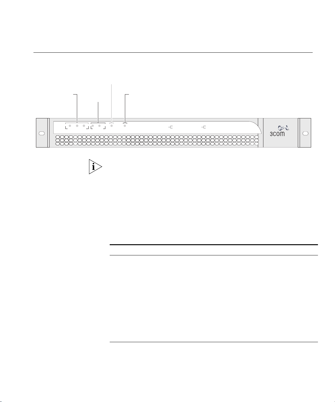
Figure 1 Webcache — Front View
Activity LED
Power/Self
test LED
LANLANLAN WAN
Activity
Activity
Power/Selftest
CacheStorage Status
green = ok
yellow = failed
Link Status
green = 100 Mbps
yellow = 10 Mbps
Webcache 3000
3C16116
SuperStack 3
®
The above illustration shows a Webcache 3000. The Webcache 1000
contains a single Cache Storage Device and therefore has one Cache
Storage Status LED on the front panel. The Webcache 3000 contains two
Cache Storage Devices and can also be upgraded with a third device in
the future; therefore it has three Cache Storage Status LEDs.
their status according to color. For information on using the LEDs for
problem solving, see “Solving Problems Indicated by LEDs” on page 32.
Tab l e 3 LED Behavior
LED Color Indicates
Cache Storage Status LED(s)
Green The cache storage device is present and operating normally.
Yellow The cache storage device has failed.
Off The cache storage device is not present.
Link Status LEDs
Green A Fast Ethernet speed (100 Mbps) link is present, and the port
is enabled.
Yellow An Ethernet speed (10 Mbps) link is present, and the port is
enabled.
Off No link is present.
(continued)
Page 20
20 CHAPTER 1: INTRODUCING THE WEBCACHE
LED Color Indicates
Activity LED
Green flashing The cache is active and caching is occurring.
Off The cache is not active. This is normal behavior for an idle
Power/Self test LED
Green The Webcache is powered-up and operating normally.
Green flashing The Webcache is either initializing or performing a software
Yellow The Webcache is powered-up but is not caching - a failure has
Off The Webcache is not powered-up. This may indicate a power
Webcache.
upgrade.
occurred.
failure.
Webcache — Rear View Detail
Power Socket The Webcache automatically adjusts its power setting to any supply
Console Port The console port allows you to connect a terminal, terminal emulator or
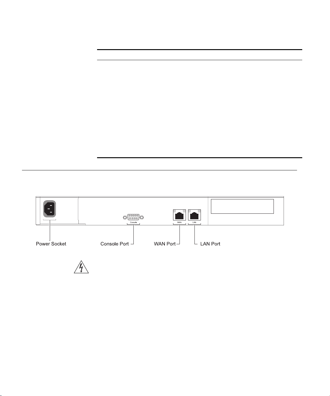
Figure 2 Webcache — Rear View
WARNING: WAN and LAN RJ-45 Ports. These are shielded RJ-45 data
sockets. They cannot be used as standard traditional telephone sockets, or to
connect the unit to a traditional PBX or public telephone network. Only
connect RJ-45 data connectors, Switches or Routers to these sockets.
Either shielded or unshielded data cables with shielded or unshielded
jacks can be connected to these data sockets.
voltage in the range 90-240 VAC.
modem and perform remote or local out-of-band management. The
Page 21
Webcache — Rear View Detail 21
console port uses a standard null-modem cable and is set to 9600 baud,
8 data bits, no parity and 1 stop bit.
WAN Port The WAN port is an auto-negotiating 10BASE-T/100BASE-TX RJ-45 port.
It is used to connect the Webcache to the network in an inline
deployment environment.
CAUTION: The Webcache does not support inline deployment in Version
1.0. You should not connect network cabling to the WAN port.
LAN Port The LAN port is an auto-negotiating 10BASE-T/100BASE-TX RJ-45 port. It
is used to connect the Webcache to the network in either Proxy or
Transparent deployment environments. Web network traffic travels to
and from the Webcache via the LAN port. For more information, see
“Deploying the Webcache in Your Network” on page 33.
You must connect the LAN port to your network using an appropriate
network cable. For more information, see the “Cable Specifications and
Pin-outs” appendix on page 147.
WAN and LAN Port
LEDs
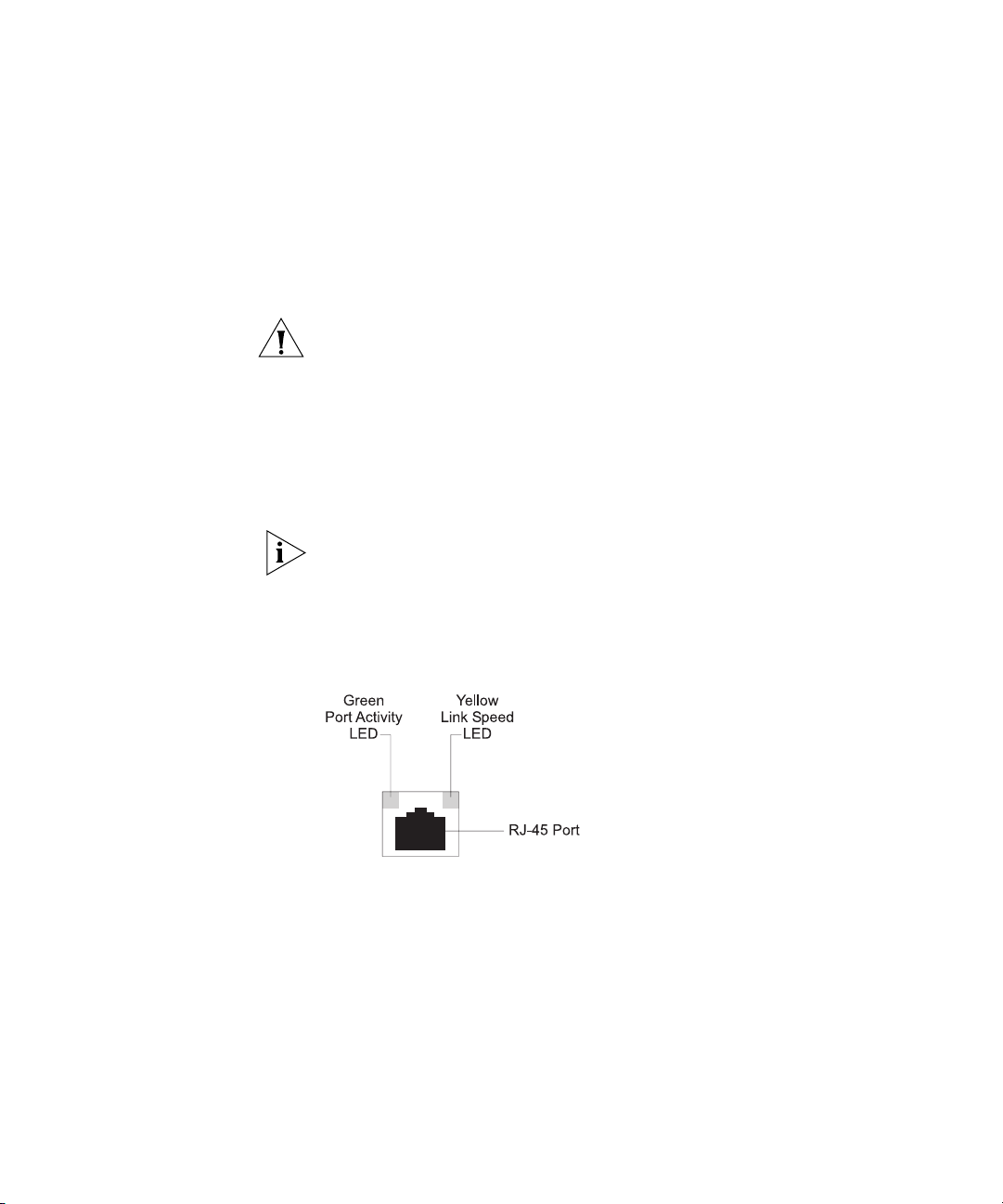
Figure 3 Webcache — WAN and LAN Port LEDs
Table 4 lists LEDs visible on the rear of the Webcache, and how to read
their status according to color. For information on using the LEDs for
problem solving, see “Solving Problems Indicated by LEDs” on page 32.
Page 22

22 CHAPTER 1: INTRODUCING THE WEBCACHE
Tab l e 4 LED Behavior
LED Color Indicates
Port Activity LED
Green On A link is present.
Green Flashing Packets are being transmitted/received on the port.
Green Off No link is present.
Link Speed LED
Yellow On A Fast Ethernet speed (100 Mbps) link is present.
Yellow Off An Ethernet speed (10 Mbps) link is present.
The Link Speed LED does not change its state if the link is broken. It
remains in its current state until a new link is established. Therefore
Green Off, Yellow On indicates that no link is present and that the link
was previously 100Mbps. It does not indicate that a 100Mbps link is still
present.
Default Settings Table 5 shows the factory default settings for the Webcache:
Tab l e 5 Default Settings
Feature Webcache 1000/3000
Port Speed 10BASE-T/100BASE-TX Mbps ports are
auto-negotiated
Duplex Mode 10BASE-T and 100BASE-TX ports are auto-negotiated
Flow Control Enabled with auto-negotiation in full duplex
Console Port 9600 Baud, 8 data bits, no parity, 1 stop bit, no flow
IP Address 192.168.1.253 non-broadcast address
Subnet Mask 255.255.255.0
Domain Name System
(DNS) Server
Default Router 0.0.0.0
Host Name Null
Domain Name System
(DNS) Domain
Caching Enabled
Caching Mode Proxy
(continued)
control
0.0.0.0
Null
Page 23

Default Settings 23
Feature Webcache 1000/3000
Caching Port 8080
Access Logging Disabled
Web Site Blocking Disabled
Web Client Blocking Disabled
Simple Network
Enabled but requires configuration
Management Protocol
(SNMP)
Network Time Protocol
Disabled
(NTP)
Web Browser
Disabled
Auto-Configuration
Upgrade Notification Enabled but requires configuration
Upgrade
Enabled
Detection/Download
Email Notification Events Disabled
Multi Router Traffic
Always Enabled
Grapher (MRTG) Graphs
admin Password (none)
Password Recovery Enabled
If you initialize the Webcache by selecting System -> Control -> Initialize
in the Web interface or by entering
system control initialize in the
Command Line Interface, the following settings are retained to allow you
to connect to and manage the Webcache:
■ IP Address
■ Subnet Mask
■ Default Router
■ Domain Name System (DNS) Server
■ Host Name
■ Domain Name System (DNS) Domain
All other settings are reset to the default values shown in Table 5.
Page 24

24 CHAPTER 1: INTRODUCING THE WEBCACHE
Page 25
2
INSTALLING THE WEBCACHE
This chapter contains the information you need to install and set up the
Webcache 1000/3000. It covers the following topics:
■ Package Contents
■ Choosing a Suitable Site
■ Rack-Mounting the Webcache
■ The Power-up Sequence
■ Deploying the Webcache in Your Network
■ Setting Up the Webcache for Management
■ Getting Started Wizard Settings
■ Connecting the Webcache to the Live Network
■ Network Configuration Concepts
WARNING: Safety Information. Before installing or removing any
components from the Webcache 1000/3000 or carrying out any
maintenance procedures, you must read the safety information provided
in Appendix A of this guide.
AVERTISSEMENT: Consignes de sécurité. Avant d'installer ou d'enlever
tout composant du Webcache 1000/3000 ou d'entamer une procédure
de maintenance, lisez les informations relatives à la sécurité qui se
trouvent dans l'Appendice A de ce guide.
WARNHINWEIS: Sicherheitsinformationen. Bevor Sie Komponenten
aus dem Webcache 1000/3000 entfernen oder dem Webcache
1000/3000 hinzufuegen oder Instandhaltungsarbeiten verrichten, lesen
Sie die Sicherheitsanweisungen, die in Appendix A (Anhang A) in diesem
Handbuch aufgefuehrt sind.
Page 26

26 CHAPTER 2: INSTALLING THE WEBCACHE
Package Contents ■ Webcache 1000 (3C16115) or Webcache 3000 (3C16116)
■ CD-ROM
■ User Guide (this guide)
■ Release Notes
■ Warranty Card
■ Power Cord
■ Rack-Mounting Kit containing:
■ 2 x Rack Mounting Rails
■ 2 x Rack Mounting Brackets
■ 2 x Adjustable Brackets
■ 2 x Front Plates
■ 16 x Screws
These items are shown in Figure 4 on page 27.
Choosing a Suitable Site
The Webcache must be mounted in a standard 19-inch 4-posted
equipment rack, and is suited for use in a wiring closet, an equipment
room, a server room, or telecommunications room. A rack-mounting kit is
supplied with the Webcache.
CAUTION: Ensure that the ventilation holes in the Webcache are not
obstructed.
When deciding where to position the Webcache, ensure that:
■ Cabling is located away from:
■ sources of electrical noise such as radios, transmitters and
broadband amplifiers.
■ power lines and fluorescent lighting fixtures.
■ The Webcache is accessible and cables can be connected easily.
■ Water or moisture cannot enter the case of the Webcache.
■ Air-flow is not restricted around the Webcache. 3Com recommends
that you provide a minimum of 25 mm (1 in.) clearance.
■ Air temperature around the Webcache does not exceed 40 °C (104 °F).
Page 27
Rack-Mounting the Webcache 27
If the Webcache is installed in a 19-inch rack or closed assembly its local
air temperature may be greater than room ambient temperature.
■ The air is as free from dust as possible.
■ The Webcache is installed in a clean, air conditioned environment.
Rack-Mounting the Webcache
The Webcache is 1U high and will fit in most standard 19-inch rack
mounts.
CAUTION: The rear of the Webcache must be supported. This is best
achieved through the use of a 19-inch 4-posted rack.
CAUTION: Disconnect all cables from the Webcache before continuing.
To rack-mount your Webcache:
1 Place the Webcache the right way up on a hard flat surface, with the
front facing towards you.
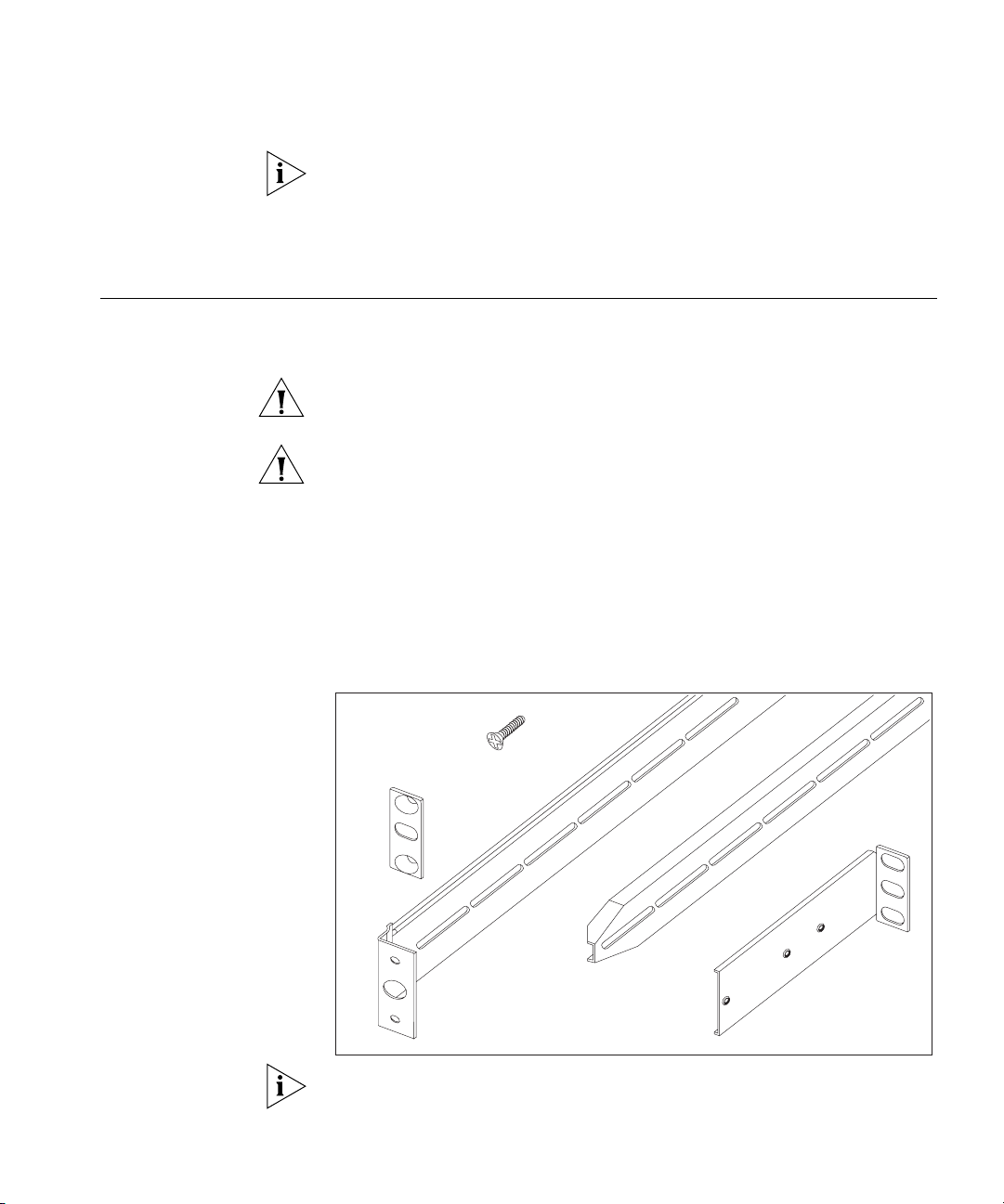
2 Locate the Rack-Mounting Kit that is supplied with the Webcache. The
Kit contains the items shown in Figure 4.
Figure 4 The Rack-Mounting Kit Contents
16 x
Screws
2x
Front
Plates
2x
Rack-Mounting
2x
Rack-Mounting
Rails
Brackets
2x
Adjustable
Brackets
You must use the rails and screws supplied with the Rack-Mounting Kit.
Damage caused to the Webcache by using incorrect rails and screws
invalidates your warranty.
Page 28
28 CHAPTER 2: INSTALLING THE WEBCACHE
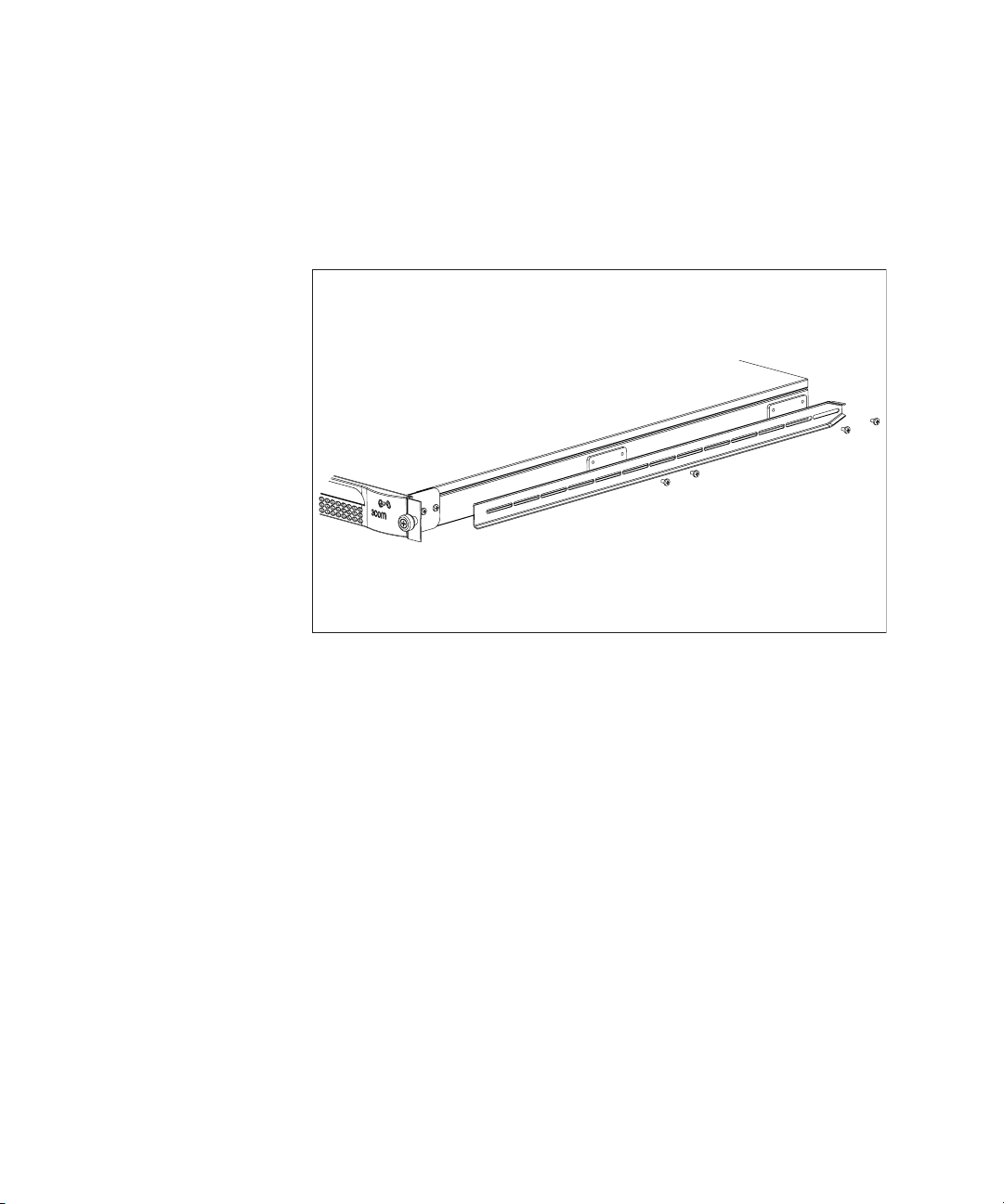
3 Attach a rack-mounting bracket to each side of your Webcache using 4
of the screws provided for each bracket, as shown in Figure 5.
Figure 5 Fitting a Rack-Mounting Bracket to the Webcache
Page 29
Rack-Mounting the Webcache 29
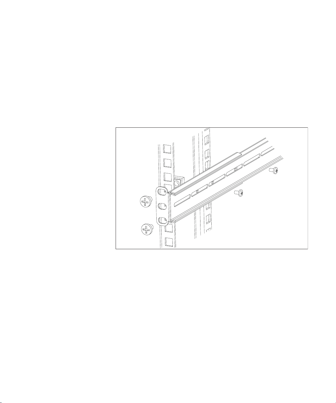
4 Use an adjustable bracket to secure a rack-mounting rail to the rear of
your rack as shown in Figure 6. To do this:
a Slide the adjustable bracket onto the rack-mounting rail and attach it
using two of the screws provided at a position suitable for your rack.
b Use rack-nuts (not supplied) to attach the rack-mounting rail and
adjustable bracket assembly to the rear of your rack.
Figure 6 Fitting a Rack-Mounting Rail to the Rear of the Rack
Page 30
30 CHAPTER 2: INSTALLING THE WEBCACHE
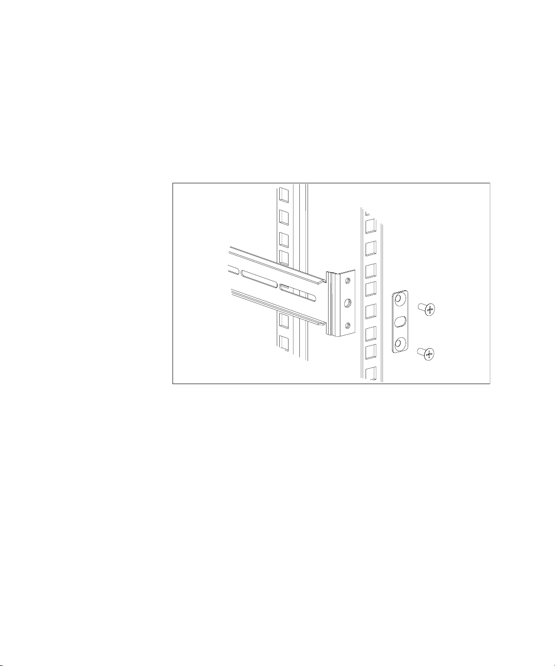
5 Attach the rack-mounting rail to the front of the rack. To do this:
a Insert two screws through aligned openings in the front plate, rack
and rack-mounting rail as shown in Figure 7.
b Tighten the screws with a suitable screwdriver.
Figure 7 Fitting a Rack-Mounting Rail to the Front of the Rack
6 Repeat step 4 and step 5 for the other side of the rack.
Page 31

The Power-up Sequence 31
7 Slide the rack-mounting brackets on the sides of the Webcache into the
rack-mounting rails.
8 Secure the front of the Webcache to the rack with the captive
thumbscrews, as shown in Figure 8.
Figure 8 Attaching the Webcache to the Rack
The Power-up Sequence
Powering-up the
Webcache
9 Ensure that the ventilation holes in the Webcache are not obstructed.
The following sections describe how to get your Webcache powered-up
and ready for operation.
Use the following sequence of steps to power-up the Webcache:
1 Plug the power cord into the power socket at the rear of the Webcache.
2 Plug the other end of the power cord into your power outlet.
3 The Webcache automatically powers-up, which takes approximately
60-90 seconds. During power-up all of the LEDs light and the Power/Self
test LED flashes green. When the Webcache has powered-up and is
operating normally, the Power/Self test LED changes to non-flashing
green.
Page 32

32 CHAPTER 2: INSTALLING THE WEBCACHE
CAUTION: The Webcache has no ON/OFF switch; the only method of
connecting or disconnecting mains power is by connecting or
disconnecting the power cord.
Checking for Correct
Operation of LEDs
Solving Problems
Indicated by LEDs
During the power-up of the Webcache, all ports on the Webcache are
disabled, all of the LEDs light and the Power/Self test LED flashes green
When the power-up has completed, check the Power/Self test LED to
make sure that your Webcache is operating correctly. Table 6 shows
possible behavior for the LED.
Tab l e 6 Power/Self test LED behavior
Color State
Green The Webcache is powered-up and operating normally.
Green flashing The Webcache is either powering-up or performing a
software upgrade.
Yellow The Webcache is powered-up but is not caching — a
Off The Webcache is not powered-up. This may also indicate
failure has occurred.
a power failure.
If the LEDs on the Webcache indicate a problem, refer to Table 7, which
contains a list of problems and suggested solutions.
Tab l e 7 Problems Indicated by LEDs
Problem Suggested Solution
The Power/Self test
LED does not light
On powering-up, the
Power/Self test LED
lights yellow
A link is connected but
the Status LED for the
port does not light
Check that the power cable is firmly connected to the
Webcache and to the supply outlet. If the connection is
secure and there is still no power, you may have a faulty
power cord.
The Webcache has failed during its power-up sequence
because of an internal problem. Contact your supplier for
advice.
Check that:
■ All connections are secure.
■ The devices at both ends of the link are powered-up.
■ The quality of cable is satisfactory.
Page 33

Deploying the Webcache in Your Network 33
ebcache
Deploying the Webcache in Your Network
You must determine how you are going to deploy the Webcache in your
network. The Webcache can be deployed in two ways:
■ Proxy Cache mode — The Webcache is connected to a Layer 2 switch
in your LAN. You must configure the Web browser on each client
machine in your network to direct its Web requests to the Webcache.
■ Transparent Cache mode — The Webcache is connected to a Layer 4
redirection device — a switch, router or firewall in your LAN which is
capable of Redirection. No configuration of the Web browser on each
client machine is needed because the Layer 4 device automatically
redirects Web requests to the Webcache.
CAUTION: 3Com recommends that you deploy your Webcache on the
LAN side of a firewall, or on the SuperStack 3 Firewall's DMZ port as
described in “Deploying the SuperStack 3 Firewall as a Proxy Forwarder”
on page 35.
The term “Web requests” refers to three types of network traffic; HTTP,
HTTPS (SSL encrypted) and HTTP-FTP. The Webcache can accept all of
these traffic types. In Proxy Cache mode, you should configure the Web
browser on each client machine to use the Webcache as the server for
each of these protocols.
HTTPS (SSL encrypted) traffic is only passed through by the Webcache; it
is not decoded or cached.
Client Machine
Client Machine
Client Machine
Proxy Cache
Figure 9 Proxy Cache Deployment
WAN Gateway
1
2
2
3
3
L
L
L
A
A
A
N
N
N
WA
N
A
A
c
c
tiv
tiv
ity
ity
P
ow
e
r/Se
lf
C
tes
a
t
c
h
e
S
to
ra
g
e
S
ta
tu
s
L
in
k
S
ta
tu
s
gree
C
n
ac
=
o
he
k
S
to
rag
e
S
tatus
We
b
c
a
c
h
e
3
gre
0
0
en
0
=
1
0
0
M
bp
s
yellow
L
in
k
=
Sta
fa
tus
ile
d
ye
llo
w
=
1
0
M
b
ps
3
C
1
6
1
1
6
®
S
u
p
e
r
S
t
a
c
k
3
W
Server
WANLAN
Server
Page 34

34 CHAPTER 2: INSTALLING THE WEBCACHE
In the Proxy Cache deployment the Webcache is connected to an
Ethernet switch in your LAN. You must configure the Web browser on
each client machine in your network to explicitly direct its Web requests
to the Webcache. For more information on Web browser configuration,
see “Configuring Web Browsers” on page 49.
All Web requests are received and served by the Webcache. All non-Web
traffic bypasses the Webcache and is sent directly to the appropriate
destination.
If the Webcache fails, access to the Web is lost because each client
machine has been configured to direct its Web requests to the
Webcache.
You can avoid this loss of access to the Web by using Proxy Auto
Configuration (PAC) files to configure the Web browser on each client
machine. The PAC file can instruct the browser to go directly to the Web
if the Webcache is not available. For more information, see page 50.
Transparent Cache
Figure 10 Transparent Cache Deployment
In the Transparent Cache deployment the Webcache is connected to a
Layer 4 switch, router or firewall in your LAN which is capable of
Redirection. The Layer 4 device (also known as a Layer 4 redirector or
Web-enabled device) automatically redirects all Web requests to the
Webcache. Therefore no configuration of the Web browser on each client
machine is needed, which avoids configuration problems and reduces the
demand on technical support.
Page 35

Deploying the Webcache in Your Network 35
If the Webcache fails, the Layer 4 device will detect the failure and
redirect Web requests to the WAN, if the device supports Webcache
health-checks, ensuring that access to the Web is maintained.
Deploying the Webcache in Transparent mode has benefits for the
security of your network. It ensures that only client machines that are
inside your network can access the systems and resources within it. This
eliminates the need for serious access controls.
Migrating from Proxy
Cache to Transparent
Cache Mode
Deploying the
SuperStack 3 Firewall
as a Proxy Forwarder
Client machines with Web browsers that are configured to use the
Webcache as a Proxy Cache (either directly or through Browser
Auto-Configuration) can continue to use the Webcache as a Proxy Cache
if you change the Webcache to a Transparent Cache deployment. This
allows you to gradually migrate the client machines in your network from
a pure Proxy Cache configuration to a pure Transparent Cache
configuration, by changing the Web browsers to Transparent Cache
mode as required.
The following example describes how to install the SuperStack 3 Firewall
(3CR16110-9x) as a Proxy Forwarder. The network layout is shown in
Figure 11 below.
Figure 11 Deploying the Firewall and Webcache Together
LAN
Infrastructure
C
C
F
S
R
Key:
F
SuperStack 3
irewallF
C
Superstack 3
Web achec
S
10/100 Mbps
witchS
R
Router
Client PC
1 Install the Webcache as described in this Chapter, taking into account any
safety information.
a Install the Webcache on a Hub or Switch connected to the DMZ port
of the Firewall. Use the LAN port of the Webcache for this connection.
Page 36

36 CHAPTER 2: INSTALLING THE WEBCACHE
Network Address Translation (NAT) does not apply to the DMZ port of the
Firewall so you will need to configure the Webcache with a registered IP
address.
b Set the Webcache to Proxy Mode. This setting can be made from the
Getting Started Wizard or by selecting Device View > System >
Caching > Set Caching Mode from the Web interface.
Setting Up the Webcache for Management
c In the Port Number field enter the number
8080 (this is the default
value).
d Do not enable Web Site Blocking on the Webcache as the Firewall has
more advanced filtering abilities and is able to use the 3Com Web Site
Filter (3C16111) if installed.
2 Install the Firewall according to the Superstack 3 Firewall User Guide
(DUA1611-0AAA0x) taking into account any safety information.
a On the Web interface of the Firewall click Advanced then Proxy Relay.
b In the Proxy Web Server Address field enter the IP address of your
Webcache.
c In the Proxy Web Server Port field enter the number
8080.
d Click Update to save your changes.
3 No configuration is necessary on the client machines. The Firewall will
intercept any HTTP requests for external URLs and will forward the traffic
to the Webcache.
You can quickly set up the Webcache for management in two ways:
■ Setting Up Using the Web Interface — Connect a management
workstation to the Webcache over an IP test network or directly via a
cross-over cable. For more information, see “Setting Up Using the
Web Interface” on page 38.
or
■ Setting Up Using the Command Line Interface — Connect a
management workstation to the Webcache over an IP test network or
connect a terminal or terminal emulator to the console port of the
Webcache directly, or through a modem. For more information, see
“Setting Up Using the Command Line Interface” on page 40.
CAUTION: You must configure the basic settings of the Webcache by
completing the Getting Started wizard before you introduce the
Page 37

Setting Up the Webcache for Management 37
Webcache to your live network. In particular, ensure that the IP settings
of the Webcache fit into those of your network. For more information,
see “Getting Started Wizard Settings” on page 43.
Before You Begin To setup the Webcache for management, you must correctly configure it
with the following information. Ensure that you have this information for
the Webcache ready before you begin.
■ An IP address — for more information, see “IP Addresses” on
page 45.
■ A subnet mask — for more information, see “Subnets and Using a
Subnet Mask” on page 46.
■ A default router address — for more information, see “Default
Router” on page 46.
■ A Domain Name System (DNS) server address — for more
information, see “Domain Name System” on page 47.
■ A Network Time Protocol (NTP) address — for more information,
see the “System Time” chapter on page 67. You can choose to enter
the system time manually instead of using NTP.
■ A Host Name — The Host Name is combined with the Domain
Name System domain to give the internet name of the Webcache.
The host name is the name of the Webcache within the local domain.
■ A Domain Name System (DNS) domain — The Domain Name
System domain is combined with the Host Name to give the internet
name of the Webcache. The domain name is a grouping of computers
with related properties. For example you might group all computers in
your company in the domain
mycompany.com.
Example
The internet (DNS) name
combining the Host Name
mycompany.com.
■ A Caching Mode — for more information, see “Deploying the
webcache.mycompany.com is formed by
webcache with the DNS domain
Webcache in Your Network” on page 33.
■ A Caching Port Number — The Caching Port Number is the port on
which the Webcache will listen for traffic. The default number is 8080.
The caching port number is only required if you set the Caching Mode
to “Proxy Mode”.
Page 38

38 CHAPTER 2: INSTALLING THE WEBCACHE
S
Clie
e
Clie
e
Setting Up Using the
Web Interface
Client Machine
Client Machine
You can setup the Webcache for management via the Web interface by
using a Web browser on a management workstation that is connected to
the Webcache over your test network, or directly using a cross-over cable.
Setting Up Over the Test Network
The Webcache is pre-configured with a default IP address, which is within
the range of addresses reserved by the IETF for private IP networks. This
default address allows you to run the Web interface without any initial
configuration of IP addresses. The default IP address of the Webcache is
192.168.1.253.
Figure 12 Setting Up Over the Test Network
witch/Hub
1
2
2
3
3
L
L
L
A
A
A
N
N
N
WA
N
A
A
c
c
ti
ti
v
v
it
it
y
y
P
o
w
e
r
/
S
e
l
f
CacheStorageStatus
t
e
s
t
LinkStatus
g
r
e
e
C
n
a
=
c
h
o
e
k
S
t
o
r
a
g
e
S
t
a
t
u
s
Webcache3000
g
r
e
e
n
=
1
0
0
M
b
p
s
y
e
L
l
l
o
in
w
k
=
S
t
fa
a
t
il
u
e
s
d
y
e
l
lo
w
=
10
M
b
p
s
3C16116
®
S
uperStack3
Webcache
To connect the Webcache to the test network:
■ The client machine must be in the same subnet as the Webcache to be
able to access it using the default IP address.
■ You must have an IP stack correctly installed on the client machine.
You can check this by trying to browse the World Wide Web; if you
can browse, an IP stack is installed. If you do not have access to the
World Wide Web, you can check that the IP stack is installed by
pinging another device in your network. For more information, see
“Pinging Other Devices” on page 91.
Setting Up Using a Cross-over Cable
Alternatively, you can directly connect a client machine to the Webcache
by attaching a cross-over cable to the LAN port on the rear panel. For
more information, see “Webcache — Rear View Detail” on page 20.
Figure 13 Setting Up Using a Cross-over Cable
Connected Using a Cross-over Cable
nt Machin
nt Machin
1
2
2
3
3
L
L
L
A
A
A
N
N
N
WA
N
CacheStorageStatus
LinkStatus
A
A
c
c
t
t
iv
iv
it
it
y
y
P
o
w
e
r
/S
e
l
f
te
s
t
g
re
e
C
n
a
=
c
h
o
e
k
S
to
r
a
g
e
S
ta
t
u
s
y
e
L
l
lo
in
w
k
=
S
ta
fa
tu
ile
d
Webcache
Webcache3000
g
re
e
n
=
1
0
0
M
b
p
s
s
y
e
llo
w
=
1
0
M
b
p
s
3C16116
®
SuperStack3
Page 39

Setting Up the Webcache for Management 39
Accessing the Web Interface
To access the Web interface:
1 Open the Web browser on the management workstation. To display the
Web interface correctly, use one of the following Web browsers:
■ Microsoft Internet Explorer v4.0
■ Microsoft Internet Explorer v5.0
■ Microsoft Internet Explorer v5.5
■ Netscape Communicator v4.5
■ Netscape Communicator v4.6
■ Netscape Communicator v4.7
Netscape Navigator version 6 is not supported by the Webcache.
For the browser to operate the Web interface correctly JavaScript™ and
Cascading Style Sheets must be enabled on your browser. These features
are enabled on a browser by default. You will only need to enable them if
you have changed your browser settings. Also the Web interface has
been optimised for PC screens with the desktop area set to 800 by 600
pixels. 3Com recommends that you set the font size to Small Fonts.
2 In the Location/Address field of the browser, enter the URL of the
Webcache. This must be in the format:
http://nnn.nnn.nnn.nnn:8081
where nnn.nnn.nnn.nnn is the IP address of the Webcache and 8081 is
the port on which the Webcache listens. You must enter
http:// and the
port number to successfully access the Webcache using your browser.
192.168.1.253 is the default IP address of the Webcache.
In Netscape, you can enter a shortened URL such as 192.168.1.253:8081
and Netscape successfully accesses the Webcache. In Internet Explorer,
however, this URL is not recognized. You must include "http://" at the
start of the URL i.e. http://192.168.1.253:8081.
3 When the browser has located the Webcache, a user name and password
screen is displayed as shown in Figure 14.
Page 40

40 CHAPTER 2: INSTALLING THE WEBCACHE
Clie
e
Clie
e
Figure 14 User name and password screen
If the user name and password screen is not displayed, see “Solving Web
Interface Problems” on page 130.
4 Enter your user name and password. For further information, see
“Logging in as a Default User” on page 58. Click OK.
5 The Getting Started wizard is displayed when the Web interface has
loaded. You must configure the basic settings of the Webcache by
completing the Getting Started wizard before you introduce the
Webcache to your live network. For more information, see “Getting
Started Wizard Settings” on page 43.
Setting Up Using the
Command Line
Interface
nt Machin
nt Machin
You can setup the Webcache for management via the Command Line
Interface by running a Telnet session on a management workstation that
is connected to the Webcache over your test network, or locally via a
console port connection.
Setting Up Over the Test Network
The Webcache is pre-configured with a default IP address, which is within
the range of addresses reserved by the IETF for private IP networks. This
default address allows you to run the Command Line Interface without
any initial configuration of IP addresses. The default IP address of the
Webcache is 192.168.1.253.
Figure 15 Setting Up Over the Test Network
Switch/Hub
1
2
2
3
3
L
L
L
A
A
A
N
N
N
WA
N
A
A
c
c
tiv
tiv
it
it
y
y
P
o
w
e
r
/
S
e
lf
CacheStorageStatus
t
e
s
t
LinkStatus
g
r
e
e
C
n
a
=
c
h
o
e
k
S
to
ra
g
e
S
ta
tu
s
Webcache3000
g
r
e
e
n
=
1
0
0
M
b
p
s
y
e
L
llo
in
w
k
=
S
ta
fa
tu
ile
s
d
y
e
ll
o
w
=
1
0
M
b
p
s
3C16116
®
SuperStack3
Webcache
Page 41

Setting Up the Webcache for Management 41
To setup the Webcache using the Command Line Interface over a test
network using Telnet, open a Telnet session using a terminal emulator by
specifying the IP address of the Webcache. If you are unsure how to do
this, check the documentation supplied with the Telnet facility
To connect the Webcache to the test network:
■ The client machine must be in the same subnet as the Webcache to be
able to access it using the default IP address.
■ You must have an IP stack correctly installed on the client machine.
You can check this by trying to browse the World Wide Web; if you
can browse, an IP stack is installed. If you do not have access to the
World Wide Web, you can check that the IP stack is installed by
pinging another device in your network. For more information, see
“Pinging Other Devices” on page 91.
Setting Up Through the Console Port
Alternatively, you can directly connect a client machine to the Webcache
by attaching a null-modem cable to the console port on the rear panel.
For more information, see “Webcache — Rear View Detail” on page 20.
Figure 16 Setting Up Through the Console Port
To connect to the Webcache via the console port:
1 You must connect a terminal or terminal emulator to the console port on
the rear panel of the Webcache. For more information, see “Webcache
— Rear View Detail” on page 20.
■ If you are connecting directly to the console port, you need a standard
null-modem cable.
■ If you are connecting to the console port using a modem, you need a
standard modem cable. The console port of the Webcache has a male
9-pin D-type connector. You can find pin-out diagrams for both cables
in the “Cable Specifications and Pin-outs” appendix on page 147.
To connect the cable:
a Attach the female connector on the cable to the male connector on
the console port of the Webcache.
Page 42

42 CHAPTER 2: INSTALLING THE WEBCACHE
b Tighten the retaining screws on the cable to prevent it from being
loosened.
c Connect the other end of the cable to your terminal, terminal
emulator, or modem. Make sure that the terminal, terminal emulator,
or modem have the same settings as the console port:
■ 8 data bits
■ no parity
■ 1 stop bit
2 To configure the settings of the terminal, terminal emulator, or modem,
see the documentation that accompanies it. You must configure the
terminal and set the line speed (baud) to 9600. You can change the baud
rate of the console port via the Web interface.
Accessing the Command Line Interface
To access the Command Line Interface, take the following steps:
1 The login sequence for the Command Line Interface begins as soon as
the Webcache detects a connection to its console port, or as soon as a
Telnet session is started.
If the login sequence does not begin immediately, press Return a few
times until it does begin. If the sequence still does not begin, see “Solving
Command Line Interface Problems” on page 133.
2 At the Login and Password prompts, enter your user name and password.
For further information, see “Logging in as a Default User” on page 58.
3 If you have logged on correctly, the Top-level menu of the Command Line
Interface is displayed as described in “Understanding the Command Line
Interface” on page 112. If you have not logged on correctly, the message
Incorrect password. is displayed and the login sequence starts again.
4 Access the Getting Started wizard, which allows you to quickly configure
the basic setup information for the Webcache.
At the Top-level menu, enter:
gettingStarted
5 The Getting Started wizard is displayed. You must configure the basic
settings of the Webcache by completing the Getting Started wizard
before you introduce the Webcache to your live network. For more
information, see “Getting Started Wizard Settings” below.
Page 43

Getting Started Wizard Settings 43
Getting Started Wizard Settings
The following table shows the settings that you can configure in both the
Web interface and Command Line Interface Getting Started wizards.
CAUTION: You must configure the basic settings of the Webcache by
completing the Getting Started wizard before you introduce the
Webcache to your live network. In particular, ensure that the IP settings
of the Webcache fit into those of your network.
Tab l e 8 Getting Started wizard Settings
Setting Meaning Default Example
System Name A name that uniquely identifies the
Webcache in your network. Can be up to
255 characters long.
Location A description that identifies the location of
the Webcache in your network. Can be up
to 255 characters long.
Contact The name of the person who is responsible
IP Address A unique IP address for the Webcache. 192.168.1.253 192.168.1.253
Subnet Mask A suitable Subnet Mask for the Webcache. (none) 255.255.255.0
Default Router IP Address The IP address of the default IP router
DNS Server IP Address The IP address of the Domain Name System
Host Name The Host Name is combined with the DNS
Domain Name System
(DNS) Domain Name
Timezone The timezone in which the Webcache will
NTP Server IP Address The IP address of a Network Time Protocol
Current Date The current day, month and year. (none) 06 March 2001
Current Time The current time in 24hr clock format. (none) 12:15:45
(continued)
for the Webcache. Can be up to 255
characters long.
(gateway) in your network.
(DNS) server in your network.
Domain Name to give the internet name of
the Webcache. The host name is the name
of the Webcache within the local domain.
The DNS Domain Name is combined with
the Host Name to give the internet name of
the Webcache. The Domain Name is a
grouping of computers with related
properties.
operate.
server.
(none) Webcache 3000 #1
(none) Main server room
(none) Joe Brown
(none) 192.168.2.0
(none) 192.168.25.0
(none) webcache
(none) mycompany.com
(GMT - 05:00)
Eastern Time (US)
(none) 200.49.40.1
(GMT) London,
Dublin, Edinburgh
Page 44

44 CHAPTER 2: INSTALLING THE WEBCACHE
Setting Meaning Default Example
Password A password for the admin user name, which
you must enter whenever you manage the
Webcache via the Web interface or
Command Line Interface. Can be up to 10
characters long, is case-sensitive and must
only contain alpha-numeric characters.
Caching Mode Choose how the Webcache is deployed
within your network - either Proxy Mode or
Transparent Mode.
Caching Port Number The port number on which the Webcache
will listen for traffic. This is only required if
you set the Caching Mode to “Proxy Mode”.
You may use any other numbers in the
range 1024-8080 and 8090-65534. 3Com
recommends you use the default port
number of 8080.
(no password) 1a2b3c4d4e
Proxy Mode N/A
8080 8080
Connecting the Webcache to the Live Network
Choosing the Correct
Cables
Connecting the
Webcache
The following sections describe how to connect the Webcache to your
live network.
3Com recommends that you use Category 5 cable to connect the LAN
port to your network — the maximum segment length for this type of
cable is 100 m (328 ft).
Use the following sequence of steps to connect the Webcache to your
network:
1 Connect an appropriate network cable to the LAN port on the rear panel
of the Webcache. Simply slot the connector on the cable into the RJ-45
LAN port. When the connector is fully in, its latch locks in place. To
disconnect the cable, push the connector’s latch in and remove it.
2 Connect the other end of the network cable to a 10BASE-T/100BASE-TX
port on a suitable switch or hub in your network. The switch or hub that
you connect the Webcache to is determined by the deployment
environment that you choose; for further information, see “Deploying
the Webcache in Your Network” on page 33.
Page 45

Network Configuration Concepts 45
Network Configuration Concepts
IP Addresses If you are uncertain about what IP addresses to assign your equipment,
The following sections explain certain key concepts of configuring your
network, which you must understand in order to set up the Webcache
successfully.
contact your network administrator.
To operate correctly, each device on your network (for example a
webcache or management station) must have a unique IP address. IP
addresses have the format nnn.nnn.nnn.nnn where n is a decimal
number between 0 and 255. An example IP address is ‘192.168.100.8’.
The IP address can be split into two parts:
■ The first part (‘192.168’ in the example) identifies the network on
which the device resides.
■ The second part (‘100.8’ in the example) identifies the device within
the network.
If your network is internal to your organization only, you may use any
arbitrary IP address. We suggest you use addresses in the series
192.168.100.X (where X is a number between 1 and 254) with a subnet
mask of 255.255.255.0.
These suggested IP addresses are part of a group of IP addresses that
have been set aside specially for use “in house” only.
CAUTION: If your network has a connection to the external IP network,
you must apply for a registered IP address. This registration system
ensures that every IP address used is unique; if you do not have a
registered IP address, you may be using an identical address to someone
else and your network will not operate correctly.
Obtaining a Registered IP Address
InterNIC Registration Services is the organization responsible for
supplying registered IP addresses. The following contact information is
correct at time of publication:
World Wide Web site: http://www.internic.net
Page 46

46 CHAPTER 2: INSTALLING THE WEBCACHE
Subnets and Using a
Subnet Mask
You can divide your IP network into sub-networks also known as subnets.
Support for subnets is important because the number of bits assigned to
the device part of an IP address limits the number of devices that may be
addressed on any given network. For example, a Class C address is
restricted to 254 devices.
If you have a small network (less than 254 devices), you may decide not
to have multiple subnets.
A subnet mask is used to divide the device part of the IP address into two
further parts:
■ The first part identifies the subnet number.
■ The second part identifies the device on that subnet.
The bits of the subnet mask are set to 1 if the device is to treat the
corresponding bit in the IP address as part of the original network
number or as part of the subnet number. These bits in the mask are set to
0 if the device is to treat the bit as part of the device number.
If you are unsure about what mask to use, 3Com suggest that you
contact your network administrator.
Default Router A Router is a device on your network which is used to forward IP packets
to a remote destination. An alternative name for a Router is a Gateway.
“Remote” refers to a destination device that is not directly attached to
the same network segment as the source device.
The source device cannot send IP packets directly to the destination
device because it is in a different network segment. Instead you configure
it to send the packets to a router which is attached to multiple segments.
When it receives the IP packets, the router determines the next network
hop on the path to the remote destination, and sends the packets to that
hop. This could either be the remote destination or another router closer
towards the destination.
This hop-by-hop process continues until the IP packets reach the remote
destination.
To configure the Webcache, enter the IP address of the default router on
the local subnet in which the Webcache is located. If no default router
Page 47

Network Configuration Concepts 47
exists on your network, enter the IP address 0.0.0.0 or leave the field
blank.
If you set the default router to 0.0.0.0 or leave it blank, the Webcache
will only be able to access devices that are in the same subnet as the
Webcache.
Domain Name System The Domain Name System (DNS) maps a numerical Internet Protocol (IP)
address to a more meaningful and easy-to-remember name. When you
need to access another device on your network, you enter the name of
the device, instead of its IP address. A Domain Name System server on
your network is contacted and asked the electronic form of the question,
“What is the IP address of the destination device?”. The DNS server is a
machine that keeps track of all the names and their equivalent numeric IP
addresses. The DNS server responds with the correct IP address (e.g.
128.118.2.23), allowing the two devices to communicate with each
other.
To enable the Domain Name System, you must setup a DNS server on
your network. If you are uncertain about how to do this, contact your
network administrator.
Domain Name System
Syntax
The following Webcache features are only available if you have setup a
DNS server:
■ Access to the Webcache by DNS Name — You can access the Web
interface or Command Line Interface of the Webcache via its DNS
name, rather than its IP address e.g. webcache.mycompany.com.
■ Web Proxy Auto-Discovery — This protocol can be used to
configure Web browsers on client machines in a Proxy Cache
deployment. For further information, see “Web Proxy Auto-Discovery
(WPAD)” on page 53.
You must use the following syntax for the Domain Name System host
name and domain name:
■ Host Name
■ The host name must be at least 1 character long.
■ The host name must not exceed 63 characters long.
■ The host name must be comprised of alphanumeric characters, -
(hyphens) and _ (underscores).
Page 48

48 CHAPTER 2: INSTALLING THE WEBCACHE
■ You cannot enter a host name starting or ending with a . (dot)
character. It must start and end with a letter or number.
■ You cannot enter a host name containing a space character.
■ Domain Name
■ The domain name must be at least 1 character long.
■ The domain name must not exceed 63 characters long.
■ The domain name must be comprised of alphanumeric characters,
- (hyphens) and _ (underscores).
■ You cannot enter a domain name starting or ending with a . (dot)
character. It must start and end with a letter or number.
■ Each part of the domain name (known as a label) must be
separated with a
■ You cannot enter a domain name which has two . (dots) next to each
other.
. (single dot).
Page 49

3
CONFIGURING WEB BROWSERS
This chapter contains information about configuring Web browsers on
client machines for use in a Webcache proxy cache deployment. It covers
the following alternative methods:
■ Manual Configuration
■ Proxy Auto Configuration (PAC) File Scripts
■ Web Proxy Auto-Discovery (WPAD)
■ Third-party Tools
For more information about Proxy Cache deployment, see “Proxy Cache”
on page 33.
No configuration of Web browsers on client machines is required for a
Webcache transparent cache deployment; for more information, see
“Transparent Cache” on page 34.
Manual Configuration
You can manually configure the Web browser on each client machine to
explicitly direct its Web requests to the Webcache.
To manually configure Internet Explorer 5:
1 Open Internet Explorer.
2 From the To ol s menu, click Internet Options.
3 Click the Connections tab.
4 Click LAN Settings.
5 Tick Use a proxy server.
6 Enter the URL or location of the Webcache in the Address field.
7 Enter the caching port number on which the Webcache is listening in the
Port field. The default port number is
8080.
Page 50

50 CHAPTER 3: CONFIGURING WEB BROWSERS
You can view the port number for the Webcache by:
a Logging into the Web Interface.
b Selecting Device View -> System -> Caching -> Set Caching Mode.
8 Click OK.
To manually configure Netscape Navigator 4.5:
1 Open Netscape Navigator.
2 From the Edit menu, click Preferences.
3 Click the Advanced category and click Proxies.
4 Select Manual Proxy Configuration.
5 Click View.
6 Enter the URL or location of the Webcache in the HTTP, Security and FTP
fields.
7 Enter the caching port number on which the Webcache is listening in
each Port field. The default port number is
8 Click OK.
8080.
Proxy Auto Configuration (PAC) File Scripts
3Com recommends that you configure the client machine that you use to
manage the Webcache so that it does not use the Webcache as a proxy
server. In Internet Explorer, select Tools -> Internet Options ->
Connections -> LAN Settings and disable Use a Proxy Server. In Netscape,
select Edit -> Preferences -> Advanced -> Proxies and select Direct
Connection to the Internet.
You can use a Proxy Auto Configuration (PAC) file to configure the Web
browser on each client machine. PAC files allow you to create
configuration rules that determine how the Web browser operates when
the Webcache is being deployed as a Proxy cache. The PAC file can be
stored either on the Webcache or a network server, and the Web browser
is set to read the PAC file when it is opened.
The main disadvantage of PAC files is that the PAC file is read once when
the Web browser is first opened, and then executed within the browser
for every object within every Web page visited. This can cause a perceived
response time degradation, although the performance degradation is
likely to be small.
Page 51

Proxy Auto Configuration (PAC) File Scripts 51
You can only use a PAC file to configure the Web browsers on client
machines when the Webcache is operating in Proxy mode.
You can use the Browser Auto-Configuration screen to create a PAC file
which is stored on the Webcache. You can configure the PAC file to:
■ Bypass the Webcache for plain host names
■ Use a backup Webcache if the first one fails
■ Directly access the Web if neither the first or second Webcache is
available
Alternatively, you can disable the PAC file that the Webcache creates and
use a different PAC file which is located elsewhere on your network.
CAUTION: If you are using Browser Auto-Configuration Files to configure
your client machine Web browser settings, and you are using Web Client
Blocking to control access to the Internet, you should ensure that Go
Direct if no Webcache Available is not ticked in the Browser
Auto-Configuration screen. If this box is ticked, the Web browser will
bypass the Webcache entirely after reading the Browser
Auto-Configuration file, and will never be blocked.
To use the Webcache as a PAC file server, first configure the Webcache
PAC file using the Browser Autoconfiguration screen:
1 Log in to the Web interface.
2 Click Device View on the Toolbar.
3 Select System -> Caching -> Browser Auto-Config in the Navigation
Tree.
4 Tick Bypass Plain Host Names if you want to configure Web browsers to
bypass the Webcache for plain host names. These are typically domain
names which do not contain dots, commonly used for Intranet sites e.g.
http://intranet
5 Tick Use Backup Cache on Cache Failure if you want to configure Web
browsers to use an alternative Webcache in your network if the first one
fails. Enter the IP address of the alternative Webcache in the Backup
Cache IP Address field. Enter the port number on which the Webcache
will be listening for network traffic in the Port field. The default port
number is 8080.
Page 52

52 CHAPTER 3: CONFIGURING WEB BROWSERS
6 Tick Go Direct if no Webcache Available if you want to configure Web
browsers to directly access the Web if the main and backup Webcaches
fail. Click OK.
You must next set the Web browser to read the PAC file for its settings.
To set Internet Explorer 5:
1 Open Internet Explorer.
2 From the To ol s menu, click Internet Options.
3 Click the Connections tab.
4 Click LAN Settings.
5 Tick Use automatic configuration script.
6 Enter the URL or location of the Webcache in the Address field in the
following format:
http://nnn.nnn.nnn.nnn:8082/
where nnn is a decimal number between 0 and 255. An example IP
address is ‘192.168.1.253’. The port number on which the Webcache
always serves PAC files is 8082; you cannot change this port number.
7 Click OK.
To set Netscape Navigator 4.5:
1 Open Netscape Navigator.
2 From the Edit menu, click Preferences.
3 Click the Advanced category and click Proxies.
4 Select Automatic Proxy Configuration.
5 Enter the URL or location of the Webcache in the Configuration location
field in the following format
http://nnn.nnn.nnn.nnn:8082/
where nnn is a decimal number between 0 and 255. An example IP
address is ‘192.168.1.253’.
In Netscape, you can enter a shortened PAC address such as
webcache:8082 and Netscape successfully configures itself using the PAC
file. In Internet Explorer, however, this address is not recognized and you
are not warned that the PAC file is being ignored. You must include
"http://" at the start of the URL i.e. http://webcache:8082.
Page 53

6 Click Reload.
7 Click OK.
Web Proxy Auto-Discovery (WPAD) 53
Web Proxy Auto-Discovery (WPAD)
The Webcache and Microsoft Internet Explorer 5 (and later versions)
support the Web Proxy Auto-Discovery (WPAD) protocol. This protocol
enables the Web browser on client machines to automatically find and
load proxy configuration information (stored in a PAC file) from a server
on your network without user intervention.
You cannot set up the 3Com Webcache to be used as a WPAD server.
The Web Proxy Auto-Discovery (WPAD) protocol is not supported by
Netscape Navigator.
You can set up a WPAD server that holds a PAC file in a suitable domain
on your network. When Internet Explorer 5 is launched it searches for a
WPAD server. The Web browser adds the subdomain “wpad” to the
beginning of the fully-qualified domain name and progressively removes
subdomains until it either finds a WPAD server answering the domain
name or reaches the third-level domain. For example, Web browsers on
client machines in the a.b.3Com.com domain would query
wpad.a.b.3Com, wpad.b.3Com.com, and then wpad.3Com.com. If a
WPAD server is found, the Web browser downloads and executes the
PAC file and configures the browser settings.
You must define your network Domain Name System (DNS) server with
the appropriate use of domains in order to use a WPAD server. For further
information about the Domain Name System, see “Domain Name
System” on page 47.
When a Web browser on a client machine is configured to use a WPAD
server on your network, there may be a pause of several seconds when it
first tries to connect to the server. The delay is caused by the Web
browser connecting to your Domain Name System (DNS) server when it is
initially started. This is normal behavior. Once the Web browser has
accessed the WPAD server, subsequent browser requests will operate
without delays caused by WPAD.
Page 54

54 CHAPTER 3: CONFIGURING WEB BROWSERS
To configure Internet Explorer 5 to use WPAD:
1 Open Internet Explorer.
2 From the To ol s menu, click Internet Options.
3 Click the Connections tab.
4 Click LAN Settings.
5 Tick Automatically detect settings.
6 Click OK.
Web Proxy
Auto-Discovery
You can view the Internet Draft for the Web Proxy Auto-Discovery
Protocol at:
Resources
http://www.ietf.org/internet-drafts/draft-cooper-webi-wpad-0
0.txt
(correct at time of publishing)
Third-party Tools There are applications from many vendors that can help you to manage
networks of client machines.
Microsoft offers the Internet Explorer Administration Kit and Systems
Management Server, which allow you to remotely configure Web
browsers and Proxy Cache settings.
http://www.microsoft.com/windows/ieak/en/default.asp
Other vendors include Hewlett Packard, Intel and Tivoli.
Page 55

II
WEBCACHE FEATURES
Chapter 4 Managing the Webcache
Chapter 5 System Time
Chapter 6 Security
Chapter 7 Controlling and Monitoring Web Access
Chapter 8 System Events
Chapter 9 Performance Monitoring
Chapter 10 System Diagnostics
Chapter 11 Software Upgrade and Installation
Page 56

56
Page 57

4
MANAGING THE WEBCACHE
This chapter contains information about managing the Webcache using
the management software that resides on the Webcache. Managing the
Webcache can help you to improve the efficiency of the Webcache and
therefore the overall performance of your network. It allows you to make
full use of the features offered by the Webcache, and to change and
monitor the way it works. The following topics are covered:
■ Management Software Interfaces
■ Logging in as a Default User
■ Accessing the Web Interface
■ Understanding the Web Interface
■ The Banner
■ The Toolbar
Management Software Interfaces
■ The Navigation Tree
■ The Information Area
You can manage the Webcache using the Web interface management
software. This is
Webcache using a Web browser that has Javascript
Webcache Online Help for detailed information about the Web interface.
The Webcache also has a Command Line Interface that allows you to
manage certain features; for more information, see the “Command Line
Interface” chapter on page 109.
Even if you do not intend to actively manage the Webcache, 3Com
recommends that you change the default password to prevent
unauthorized access to your Webcache. See “Setting Passwords” on
page 71 for more information.
an internal set of Web pages that allow you to manage the
™
enabled. Refer to the
Page 58

58 CHAPTER 4: MANAGING THE WEBCACHE
Logging in as a Default User
Accessing the Web Interface
If you manage the Webcache using the Web interface or the Command
Line Interface, you need to log in with a valid user name and password.
The Webcache has one user name, which is listed in Table 9. You cannot
create new user names for the Webcache.
Tab l e 9 User Names
Default
User name
admin (no password) The user can access and change all manageable
Password
Access Level
parameters
CAUTION: To prevent unauthorized access and configuration of the
Webcache, 3Com recommends that you set a password for the admin
user name as soon as possible.
The admin user name is case-sensitive.
To access the Web interface:
1 Open the Web browser on the management workstation. To display the
Web interface correctly, use one of the following Web browsers:
■ Microsoft Internet Explorer v4.0
■ Microsoft Internet Explorer v5.0
■ Microsoft Internet Explorer v5.5
■ Netscape Communicator v4.5
■ Netscape Communicator v4.6
■ Netscape Communicator v4.7
Netscape Navigator version 6 is not supported by the Webcache.
For the browser to operate the Web interface correctly JavaScript and
Cascading Style Sheets must be enabled on your browser. These features
are enabled on a browser by default. You will only need to enable them if
you have changed your browser settings. Also the Web interface has
Page 59

Accessing the Web Interface 59
been optimized for PC screens with the desktop area set to 800 by 600
pixels. It is also recommended to set the font size to Small Fonts.
2 In the Location/Address field of the browser, enter the URL of the
Webcache. This must be in the format:
http://nnn.nnn.nnn.nnn:8081
where nnn.nnn.nnn.nnn is the IP address of the Webcache and 8081 is
the port on which the Webcache listens. You must enter
http:// and the
port number to successfully access the Webcache using your browser.
192.168.1.253 is the default IP address of the Webcache.
In Netscape, you can enter a shortened URL such as 192.168.1.253:8081
and Netscape successfully accesses the Webcache. In Internet Explorer,
however, this URL is not recognized. You must include "http://" at the
start of the URL i.e. http://192.168.1.253:8081.
3 When the browser has located the Webcache, a user name and password
screen is displayed as shown in Figure 17.
Figure 17 User Name and Password Screen
If the user name and password screen is not displayed, see “Solving Web
Interface Problems” on page 130.
4 Enter your user name and password. For further information, see
“Logging in as a Default User” on page 58. Click OK.
Page 60

60 CHAPTER 4: MANAGING THE WEBCACHE
Understanding the Web Interface
Figure 18 The Web Interface
The Web interface is made up of four areas:
■ The Banner
This is always displayed at the top of the browser window. It displays
®
the 3Com logo and SuperStack
■ The Toolbar
logo.
This is always displayed at the top of the browser window, underneath
the Banner. It contains three buttons which allow you to select
different views in the View Area.
■ The Navigation Tree
This is always displayed on the left side of the browser window. It
contains various icons which allow you to manage your Webcache.
■ The Information Area
This is always displayed on the right side of the browser window. It
contains information about the managed Webcache.
The Banner The Banner is always displayed at the top of the browser window. It
displays the 3Com logo and SuperStack logo.
Page 61

The Toolbar 61
The Toolbar The Toolbar is always displayed at the top of the browser window,
underneath the Banner. It contains three buttons which allow you to
select different views:
■ The Summary View
Click Summary to display the Summary View. This view allows you to
update the latest summary information for the Webcache.
■ The Device View
Click Device View to display the Device View. This view allows you to
configure the physical and networking aspects of the Webcache.
■ The Help View
Click Help to display the Help View. This view allows you to access the
Online Help system for the Webcache, additional information from the
3Com Web site and provides specification guidelines for running the
Web interface.
The Summary View Click Summary on the Toolbar to access the Summary View. This is the
default view when you first browse to the Webcache and when you click
the browser Refresh button.
Click the System icon in the Navigation Tree to update the Information
Area with the latest summary information for the Webcache.
The summary information is displayed in a table:
■ Device Summary
The table is entitled System Summary and displays information for the
Webcache. It shows the System Name, Location, Contact, Up Time,
Type, Software Version, Hardware Version and IP Address of the
Webcache.
The Summary View only displays information for the Webcache. You
cannot perform any operations from this view. You must use the Device
View to perform operations.
The Device View Click Device View on the Toolbar to access the Device View. This view
allows you to configure the physical and networking aspects of the
Webcache.
Page 62

62 CHAPTER 4: MANAGING THE WEBCACHE
The Device View Navigation Tree is displayed on the left side of the
browser window and allows you to perform operations for the
Webcache.
The Device View Information area is displayed on the right side of the
browser and contains the device mimic and the Device Summary table.
Device Mimic
Figure 19 The Device Mimic
The device mimic is a virtual, interactive representation of the Webcache.
All of the ports on the Webcache are shown, even though the LAN, WAN
and Console ports are actually located on the rear of the unit. The device
mimic is periodically updated to reflect changes in the Webcache. You
can also perform certain operations by clicking on parts of the device
mimic called “hotspots”:
■ Console Port Hotspot
The Console Port on the mimic is a “hotspot”. Click the port to open
a pop-up menu that contains an operation which you can launch for
the console port.
The operation is Setup Console Port.
■ LAN Port Hotspot
The LAN Port on the mimic is a “hotspot”. Click the port to open a
pop-up menu that contains an operation which you can launch for the
LAN port.
The operation is Clear Cache.
■ Unit Hotspot
The non-port area of the mimic is a “hotspot”. Click anywhere on this
area to open a pop-up menu that contains operations which you can
launch for the Webcache as a whole.
The operations are:
Page 63

The Toolbar 63
■ Web Client Blocking
■ Web Site Blocking
■ Save Configuration
■ Notepad
■ System Information
Device Summary
A table entitled Device Summary displays the following information for
the Webcache. It shows the DNS Name, Type, Software Version,
Hardware Version, IP Address, MAC Address, Boot Version, Product
Number, Serial Number and Up Time of the Webcache.
The Help View Click Help on the Toolbar to access the Help View. This view allows you to
access the Online Help system for the Webcache, additional information
from the 3Com Web site and provides specification guidelines for
running the Web interface.
The Help View Navigation Tree contains five options that allow you to
access additional information from the 3Com Web site. Your
management workstation must have access to the Web for the first four
options to work:
■ Click Contacts to display contact information from the 3Com Web site
in a new browser window.
■ Click Home Page to display the Home page of the 3Com Web site in a
new browser window.
■ Click Library to display the Online Library of the 3Com Web site in a
new browser window.
■ Click Support to display support information from the 3Com Web site
in a new browser window.
■ Click On-line Help to display the Webcache Online Help system in a
new browser window.
The Help View Information Area provides specification guidelines for
running the Web interface. It is recommended that you access the Web
Interface using the suggested Web Browsers and PC Platforms.
Page 64

64 CHAPTER 4: MANAGING THE WEBCACHE
The Navigation Tree The Navigation Tree is always displayed on the left side of the browser
®
window. It is a Windows
icons which allow you to manage your Webcache.
By default, when you open the Web interface, the Summary View is
selected and the Navigation Tree is fully collapsed with only the top-level
options displayed.
Operations that you can perform to manage your Webcache are grouped
into folders within the Navigation Tree in the Device View. You can also
perform some operations by using the device mimic.
Click the folders or the nodes (the plus and minus symbols) to expand
and collapse the Navigation Tree.
Every option within the Navigation Tree is selected by single-clicking the
left mouse button.
The following table shows the various Navigation Tree symbols and their
associated behavior:
Symbol Behavior
Indicates that the next level of the Navigation Tree hierarchy is currently expanded. Click the
symbol to collapse the next level. This only affects the Navigation Tree — no changes are
made to the Information Area.
Explorer-like interface that contains various
(continued)
Indicates that the next level of the Navigation Tree hierarchy is currently collapsed. Click the
symbol to expand the next level to its last expanded state. This only affects the Navigation
Tree — no changes are made to the Information Area.
Indicates that the next level of the Navigation Tree hierarchy is currently expanded. Click the
symbol to collapse the next level. This only affects the Navigation Tree — no changes are
made to the Information Area.
Indicates that the next level of the Navigation Tree hierarchy is currently collapsed. Click the
symbol to expand the next level. This only affects the Navigation Tree — no changes are
made to the Information Area.
Page 65

Symbol Behavior
Click the symbol to update the Information Area with the latest summary information for the
Stack and the units within it. This symbol is only available in the Summary View.
Click the symbol to perform an operation by opening a new window.
Click the symbol to open a wizard in a new window.
Click the symbol to launch a Help operation.
The Information Area 65
The Information Area
The Information Area is always displayed on the right side of the browser
window. It contains information about the managed Webcache.
If the Summary View is currently selected, a table is displayed which
shows summary information for the Webcache.
If the Device View is currently selected, the Device Mimic and the Device
Summary table are displayed.
If the Help View is currently selected, specification guidelines for running
the Web interface are displayed.
Page 66

66 CHAPTER 4: MANAGING THE WEBCACHE
Page 67

5
SYSTEM TIME
This chapter explains how to configure the system time of the Webcache.
It contains the following topics:
■ Configuring the System Time
■ What is the Network Time Protocol?
■ Choosing a Network Time Protocol Server
■ Configuring the System Time Using the Network Time Protocol
■ Configuring the System Time Manually
■ System Time and Performance Graphs
Configuring the System Time
You must select how the Webcache determines the current time during
the Getting Started wizard, which automatically runs when you first
access the Webcache’s Web interface.
You can change how the Webcache determines the current time at any
point using the Time Configuration wizard. Select System ->
Management -> Time Configuration in the Navigation Tree to access
the wizard.
You can configure the system time in either of the following ways:
■ Configuring the System Time Using the Network Time Protocol — for
more information, see page 69
■ Configuring the System Time Manually — for more information, see
page 69.
3Com recommends that you use the Network Time Protocol to configure
the system time of the Webcache.
Page 68

68 CHAPTER 5: SYSTEM TIME
What is the Network Time Protocol?
Choosing a Network Time Protocol Server
The Network Time Protocol (NTP) is used to synchronize the time of client
machines and servers with other well-known, highly accurate servers or
reference time sources. It maintains a consistent Coordinated Universal
Time (UTC) within your network which is far more accurate than the
internal system clocks of client machines and prevents time drift from
occurring on the Webcache.
NTP provides client machine and server time accuracies typically within a
millisecond on LANs, relative to a primary NTP server synchronized to UTC
via a Global Positioning Service (GPS) receiver. Such accurate
time-keeping is an essential part of the operation of the Webcache.
You can choose to use one of the many public NTP servers that are
available on the Internet or set up your own NTP server. When you have
access to an NTP server, you can configure the Webcache to determine
the current time using NTP; see “Configuring the System Time Using the
Network Time Protocol” on page 69 for more information.
Public NTP servers are grouped into stratums. The NTP primary (stratum 1)
servers are connected to a reference clock, which is typically an expensive
cesium clock or cheaper GPS receiver. Servers operating at stratum 1 are
the most accurate available, but also the fewest in number because of
the prohibitive cost of reference clocks.
The NTP secondary (stratum 2) servers are in turn connected to a stratum
1 server and are therefore less accurate but greater in number. Stratum 3
servers are connected to stratum 2 servers, and so on, up to an imposed
limit of 15 strata. You should not use a high level public stratum server
because of their limited number and because the load placed on them is
increasingly heavy.
3Com recommends that if your network has an internal NTP server, you
should use this rather than a public stratum server. If not, you should use
the lowest stratum public NTP server available to you.
Page 69

Configuring the System Time Using the Network Time Protocol 69
Configuring the System Time Using the Network Time Protocol
Configuring the System Time Manually
To configure the system time of the Webcache using the Network Time
Protocol, you must enter the following information in the Getting Started
wizard or Time Configuration command in the Web interface:
1 Select a timezone from the options in the Timezone drop-down list.
The Webcache automatically performs daylight savings adjustments
according to the timezone that you have selected.
2 Choose Network Time Protocol by clicking the appropriate radio button.
3 Enter the IP address of the NTP server that you want to use in the NTP
Server IP Address field.
To manually configure the system time of the Webcache, you must enter
the following information in the Getting Started wizard or Time
Configuration command in the Web interface:
1 Select a timezone from the options in the Timezone drop-down list.
The Webcache automatically performs daylight savings adjustments
according to the timezone that you have selected.
2 Choose Manual Time Configuration by clicking the appropriate radio
button.
System Time and Performance Graphs
3 Enter the current day, month, year and the current time (in 24 hour clock
format) in the appropriate fields.
4 Click Apply Now as soon as you have manually entered this information
to ensure the greatest accuracy. You cannot click Next until you have
done this.
When the system time of the Webcache is set manually, all of the current
Performance Graphs are reset and all previous graph history is lost. You
should therefore only change the system time when it is absolutely
necessary. The following system time changes affect the Performance
Graphs in this way:
■ The system time is manually configured.
■ The system time is changed from Network Time Protocol to Manual
Time Configuration, or vice versa.
■ The IP address of the Network Time Protocol server is changed.
Page 70

70 CHAPTER 5: SYSTEM TIME
A Warning window appears asking if you want to continue with the
system time change. Click Yes to continue and reset the Performance
Graphs, or No to cancel the change.
Page 71

6
SECURITY
This chapter contains information about ensuring that the Webcache
1000/3000 is secure. It covers the following topics:
■ What are Passwords?
■ Setting Passwords
■ What is Password Recovery?
■ Enabling/Disabling Password Recovery
■ Performing Password Recovery
What are Passwords?
Setting Passwords To set the password using the Web interface, you need to login as the
Whenever you manage the Webcache using the Web interface or
Command Line Interface, you need to log in with the admin username
and password, as described in “Logging in as a Default User” on
page 58.
CAUTION: To prevent unauthorized access and configuration of the
Webcache, 3Com recommends that you set a password for the admin
username as soon as possible.
admin user and select Security -> Set Password in the Navigation Tree
to access the Password Configuration screen. Then follow the steps
below.
You are prompted to set a password for the admin user account during
the Getting Started wizard, which automatically runs when you first
access the Webcache’s Web interface.
Page 72

72 CHAPTER 6: SECURITY
You must enter the following information in both the Getting Started
wizard and the Password Configuration screen:
1 Choose between the following options by clicking the appropriate radio
button:
■ Do Not Change Password
■ Change Password for the Account
■ Set Admin Password to the Factory Default Setting
2 Either:
■ If you choose Do Not Change Password, the existing password will not
be changed.
■ If you choose Change Password for the Account, enter a new
password in the Password field and enter it again in the Confirm field.
Passwords can be up to 10 characters long, are case-sensitive and must
only contain alpha-numeric characters.
■ If you choose Set Admin Password to the Factory Default Setting, the
password is automatically set to the default for the admin user
account (no password).
What is Password Recovery?
Enabling/Disabling Password Recovery
If you forget the password for the admin user account, you will no longer
be able to perform important management operations on the Webcache.
Password Recovery allows you to define a new password for the admin
account, even though you have forgotten the current one, and regain
access to the management interfaces.
In order to perform password recovery, Password Recovery must be
enabled on the Webcache.
Password Recovery is enabled by default on the Webcache. You will only
need to complete the following steps if you want to check that password
recovery is enabled, or if you know that it has previously been disabled.
You may want to disable password recovery if you are concerned about
the security of the Webcache. When password recovery is enabled,
Page 73

Performing Password Recovery 73
anyone who has physical access to the Webcache can potentially change
the password and lock you out of the management interfaces.
CAUTION: 3Com recommends that you leave Password Recovery
enabled. If you disable it and subsequently forget the password for the
admin username, you will have to return the Webcache to 3Com.
To enable or disable Password Recovery using the Web interface:
1 Log in to the Web interface.
2 Click Device View on the Toolbar.
3 Select Security -> Recovery in the Navigation Tree. The
Password Recovery screen is displayed.
4 Check Enable Password Recovery Feature to enable Password Recovery,
or uncheck Enable Password Recovery Feature to disable it.
5 Click OK.
Performing Password Recovery
Use the password recovery method outlined below to define a new
password for the admin username:
1 Access the Command Line Interface and enter the username “recover”
and password “recover” to place the Webcache in password recovery
mode. The Webcache remains in password recovery mode for a
maximum of 30 seconds, before it returns to the CLI login prompt.
2 Reboot the Webcache whilst it is in password recovery mode by removing
the power cord from the power socket at the rear of the Webcache and
reinserting it.
3Com recommends that you access the CLI in this instance by connecting
a standard null-modem cable to the console port on the Webcache. This
enables you to be physically close enough to the Webcache to reboot the
Webcache before password recovery mode resets.
You cannot use a soft reboot operation to reset the password of the
admin username. This will end the password recovery procedure and
return you to the CLI login prompt.
3 When the Webcache has rebooted enter a new password for the admin
username.
4 Enter
enable to leave password recovery enabled, or enter disable to
turn it off. You are now logged in as the default admin user.
Page 74

74 CHAPTER 6: SECURITY
Page 75

7
CONTROLLING AND MONITORING
EB ACCESS
W
This chapter contains information about controlling the access of the
users of your network through the Webcache to the Internet. It covers
the following topics:
■ What is Web Site Blocking?
■ Configuring Web Site Blocking
■ Customizing the Response
■ What is Web Client Blocking?
■ Configuring Web Client Blocking
■ What is Access Logging?
■ Configuring Access Logging
■ Viewing the Access Log
What is Web Site Blocking?
■ Analyzing the Access Logs
Web Site Blocking allows you to control which Web sites can be accessed
through the Webcache. If you enable web site blocking, you can enter
the domain names of Web sites that you want to either allow or deny
access to. You can specify one of two blanket rules with exceptions;
either “Deny access to all sites except...” the ones that you enter, or
“Allow access to all sites except...” the ones that you enter. Web requests
from client machines will then either be served or blocked by the
Webcache, according to the rules that you have set up. A customizable,
automatically generated Web page informs the end user that access to
the Web site has been denied.
Page 76

76 CHAPTER 7: CONTROLLING AND MONITORING WEB ACCESS
Configuring Web Site Blocking
To configure Web Site Blocking using the Web interface:
1 Log in to the Web interface.
2 Click Device View on the Toolbar.
3 Select System -> Caching -> Web Site Blocking in the Navigation Tree.
4 Check Enable Web Site Blocking.
5 Select Deny Access to All Sites to deny access to all Web sites except the
ones that you enter in the list, or select Enable Access to All Sites to allow
access to all Web sites except those listed.
6 In the Except the Following field, enter the domain name of the Web site
you want to exclude from the option you chose in step 5 and click Add.
Repeat this for each Web site that you want to block.
Example
You can enter
auctions.yahoo.com to block access to that subdomain.
yahoo.com to block access to that entire domain, or enter
Domain Name Rules
■ You cannot enter a domain starting with http:.
■ You cannot enter a domain containing the / (forward slash) character.
Customizing the Response
■ You cannot enter a domain containing a space character.
■ You cannot enter a domain starting or ending with a . (dot) character.
The domain must start and end with a letter or number.
■ The domain name can only contain the following characters:
■ Uppercase A-Z and lowercase a-z
■ Any digit 0-9
■ Hyphen characters (-)
■ The domain name must be at least 1 character long.
■ The domain name must not exceed 63 characters long.
You can modify the response screen that is automatically generated by
the Webcache when a client machine tries to access a Web site that is
blocked. This allows you to enter additional information to make the
response screen more user friendly. For example, you could add “Access
Page 77

What is Web Client Blocking? 77
to this website has been denied. If you do not agree with this site being
blocked, please contact extension 1234”.
To customize the response using the Web interface:
1 Click Device View on the Toolbar.
2 Select System -> Caching -> Customize Response in the Navigation
Tree.
3 Enter up to 512 characters of text or HTML code in the Add This Text field
that you want to add to the response screen that informs the end user
that access has been denied. The text or HTML that you enter will be
appended to the standard text that appears, which is “You are not
authorized to view this page”. You cannot change or delete this standard
text.
4 If you want to view your changes before saving them to check that your
text or HTML is correct, click Preview.
Click OK to save the text or HTML code that you have entered.
There is a default option in Microsoft Internet Explorer 4 and later
versions that will cause a “friendly HTTP error message” to be displayed
when a Web site is blocked, rather than the response page generated by
the Webcache. You can turn this setting off by selecting Tools -> Internet
Options -> Advanced and unchecking Show friendly HTTP error
messages. The response page generated by the Webcache will never be
displayed by Internet Explorer if you do not change this setting. The
following Microsoft knowledgebase article describes the use of friendly
HTTP-status error messages:
http://support.microsoft.com/support/kb/articles/Q218/1/55.A
SP
What is Web Client Blocking?
Web Client Blocking allows you to control which client machines in your
network can access the Web through the Webcache. If you enable Web
Client Blocking, you can enter the static IP addresses or IP address ranges
of client machines that you want to allow access to the Web through the
Webcache. Web access from all other client machines will be denied by
the Webcache.
Dynamic Host Configuration Protocol (DHCP) servers can be used with
Web Client Blocking in two ways:
Page 78

78 CHAPTER 7: CONTROLLING AND MONITORING WEB ACCESS
■ You can configure your network into subnets and assign specific client
machine MAC addresses to be provided IP addresses within specific
subnets by DHCP. You can then prevent specific subnet IP address
ranges from accessing the Web through the Webcache through Web
Client Blocking.
For example, you configure your user group A to use a subnet defined
as 10.1.2.0-255, and group B to use another subnet defined as
10.1.3.0-255. If you want to prevent group B from accessing the Web,
you would add the subnet 10.1.3.0-255 to the Web Client Blocking
configuration. Group B would then be unable to access the Web,
while group A would have access.
■ You can configure your DHCP server to return specific IP addresses
based on the requesting client machine’s MAC address. You can
configure Web Client Blocking to block either specific client machine
IP addresses, or ranges of IP addresses, as appropriate.
Configuring Web Client Blocking
To configure Web Client Blocking using the Web interface:
1 Log in to the Web interface.
2 Click Device View on the Toolbar.
3 Select System -> Caching -> Client Machine Blocking in the
Navigation Tree.
4 Check Block Access From All Web Clients to enable Web Client Blocking.
5 In the Except these IP Addresses field, type the IP addresses or IP address
ranges of the client machines that you want to allow access and click
Add.
Example
You can enter
address range, or enter
216.115.105.2-217.115.105.2 to allow access for that IP
216.115.105.2 to allow access for that IP
address. Separate individual ranges or addresses with a comma.
CAUTION: If the browser on the client machine that you are using to
configure the Webcache is also using the Webcache as a proxy, and you
enable Web Client Blocking, you must ensure that you add the client
machine to the Except these IP Addresses field. If you do not do this,
access from the client machine to the Webcache will be blocked,
Page 79

What is Access Logging? 79
preventing you from using the Web interface.You can regain access by
either:
■ Changing the client machine’s browser settings to remove the use of
the Webcache as a proxy or
■ Using a browser on a client machine whose IP address is not blocked
by Web Client Blocking to access the Web Interface.
CAUTION: If you are using Browser Auto-Configuration Files to configure
your client machine Web browser settings, and you are using Web Client
Blocking to control access to the Internet, you should ensure that Go
Direct if no Webcache Available is not checked in the Browser
Auto-Configuration screen. If this box is checked, the Web browser will
bypass the Webcache entirely after reading the Browser
Auto-Configuration file, and will never be blocked. For more information,
see “Proxy Auto Configuration (PAC) File Scripts” on page 50.
What is Access Logging?
Access Logging allows you to track which client machines have accessed
which Web sites through the Webcache. By default Access Logging is
disabled. If you enable Access Logging you must specify a FTP server that
you want to periodically save the log to. The log is saved to the FTP server
whenever the log is approaching full, or every 6 hours, whichever comes
first. You can see a complete history of every web request made through
the Webcache by combining all the FTPed logs; the saved logs are based
on the standard Squid access log format and can be analyzed using
off-the-shelf log analysis tools.
An SNMP trap is automatically generated if the Webcache fails to save
the access log to the FTP server.
The access logs contain the following fields:
Table 10 Access Log Fields
Field Description
Time A timestamp expressed as Coordinated Universal Time (UTC) with a
millisecond resolution.
Elapsed The amount of time in milliseconds that the Webcache took to serve
the request.
Client The IP address of the requesting client machine.
(continued)
Page 80

80 CHAPTER 7: CONTROLLING AND MONITORING WEB ACCESS
Field Description
Action/Code Information on the kind of request and how it was satisfied or how
it failed i.e. was the request a hit, miss or an error.
Size The amount of data that was delivered to the client machine in
Method The way in which the Web object was requested i.e. GET,
URL The URL that the client machine requested.
Ident No value is returned for this field.
Hierarchy/From These fields are not applicable to the Webcache.
Content The content type of the Web object.
bytes, including headers.
CONNECT, TRACE.
Configuring Access Logging
To configure Access Logging using the Web interface:
1 Log in to the Web interface.
2 Click Device View on the Toolbar.
3 Select System -> Caching -> Access Logging in the Navigation Tree.
4 Check Enable Access Logging. You can view the last 256 lines of the
Access Log using the View Access Log command; for more information,
see “Viewing the Access Log” on page 81.
5 Check Enable Web Access Log Save to FTP Server if you want to save the
access logs onto an FTP server that you specify.
6 In the FTP Server Address field, enter the IP address of the FTP server that
you want to save the access logs to.
7 In the Directory field, enter the full path within the FTP server that you
want to save the access logs to.
The directory can only contain alphanumeric and “/”, “.”, “-” or “_”
characters and can only be up to 32 characters in length.
8 In the Username field, enter the user name for the FTP server that you
want to save the access logs to.
9 In the Password field, enter the password for the username entered in
step 8. The password must be between 1 and 32 characters in length.
When a password has been set,
********** is displayed in the Password
field, regardless of how many characters the password actually has. You
Page 81

Viewing the Access Log 81
can change the password by clicking Change Password and entering the
new password.
10 If you want to test and upload the Access Log now, click FTP Now. Enter a
filename for the log and click OK. The filename can only contain
alphanumeric and . (dot), - (hyphen) or _ (underscore) characters and can
only be up to 32 characters in length.
Clicking FTP Now will immediately FTP the currently active Access Log to
the FTP server. This allows you to test your FTP settings or to save the
Access Log without waiting for the next automatic FTP. Since the
Webcache may still be writing to the Access Log, using FTP Now may
result in an incomplete record at the end of the saved Access Log.
If no client machines have accessed a Web site through the Webcache
before you click FTP No w, then an empty log file will be saved on the FTP
server.
Viewing the Access Log
Analyzing the Access Logs
To view the Access Log using the Web interface:
1 Log in to the Web interface.
2 Click Device View on the Toolbar.
3 Select System -> Caching -> View Access Log in the Navigation Tree.
4 The last 256 lines of the Access Log are displayed.
Click Refresh to update the information that is displayed.
If the Webcache is deployed in Proxy mode, multiple entries for the pages
in the Web interface itself will be made in the Access Logs. This is
standard behavior for the Webcache, as it is "seeing" the requests for the
Web interface pages and logging these requests in the Access Logs. You
should either leave the Web Interface open for only short periods of time
to reduce the entries made, or use a log analyzer tool such as Webtrends
to view and analyze the Access Logs.
The access logs that have been saved on the FTP server are based on the
native Squid format. This is optimized for efficient generation and can be
analyzed using a wide variety of off-the-shelf log analysis tools.
Page 82

82 CHAPTER 7: CONTROLLING AND MONITORING WEB ACCESS
3Com recommends that you use Webtrends Log Analyzer to analyze the
access logs that the Webcache produces:
http://www.webtrends.com
Page 83

8
SYSTEM EVENTS
This chapter contains information about the system events that can occur
on the Webcache 1000/3000. It covers the following topics:
■ What are System Events?
■ Email Notification
■ SNMP Traps
What are System Events?
Email Notification You can configure the Webcache to automatically send emails to
Configuring Email
Notification
System events are events that occur on the Webcache which can be
reported to you. They range in significance from minor, such as Upgrade
Started, to major, such as System Failure. You can configure the
Webcache to automatically inform you about these events using email
notification and SNMP traps. Such notification allows you to respond
more quickly to Webcache events and helps save you valuable time and
effort. It is an important element in the remote management of the
Webcache.
specified email accounts when certain significant system events occur.
The emails are generated internally within the Webcache in a fixed
format that is also used by 3com Network Supervisor. The emails can be
sent to as many accounts as you like.
To configure Email Notification using the Web interface:
1 Log in to the Web interface.
2 Click Device View on the Toolbar.
3 Select System -> Management -> Events -> Email Notification in the
Navigation Tree. The Email Notification screen is displayed.
Page 84

84 CHAPTER 8: SYSTEM EVENTS
4 Check Enable Email Notifcation of System Events.
5 In the SMTP IP Address field, enter the IP address of the server to which
6 In the From Addresses for Notifications field, enter the address of the
the email notifications from the Webcache will be sent.
CAUTION: To use the email notification feature, you must enter the IP
address of an SMTP server that does not require SMTP authentication in
the SMTP IP Address field in the Email Notification screen.
email account from which the email notifications will appear to be sent
from.
CAUTION: If you do not enter a valid email address, the email
notifications will be rejected by the server that you entered in the SMTP
Name/IP address field. A valid email address is a fully specified address
containing a domain name, for example “webcache@3com.com”. The
partial address “webcache” would be rejected by the server.
3Com recommends that you use the domain name of the Webcache as
the email address. If you have entered “webcache” as the host name and
“mycompany.com” as the DNS domain name of the Webcache, then you
would enter “webcache@mycompany.com” as the email address.
7 In the To Addresses to Receive Notifications field, enter the addresses of
all the email accounts that will receive the email notifications. Ensure that
you separate each address with a comma. You can enter up to 255
characters in this field.
8 You can configure the Webcache to send an email notification when
certain system events occur by checking the relevant boxes:
■ Webcache Software Upgrade Events
This includes the following events:
■ A new software upgrade is available.
This email notification will only be sent if you have enabled automatic
software upgrade detection on the Webcache. You can do this using the
Upgrade Settings screen.
■ A software upgrade has succeeded.
■ A software upgrade has failed.
■ Webcache System Failure Events
This includes the following events:
■ The Webcache has failed its Power On Self Test.
Page 85

SNMP Traps 85
System Failure is also indicated by a yellow Power/Self Test/System Fault
LED on the front panel of the Webcache; for more information, see the
“Introducing the Webcache” chapter on page 17.
■ A cache storage device has failed.
9 Click OK.
SNMP Traps You can configure the Webcache to automatically generate Simple
Network Management Protocol (SNMP) traps when certain significant
system events occur. An SNMP trap is a message generated by the
Webcache in response to a particular event. It is sent to a specified
network management station in your network which receives and filters
it. You can configure the network management station to log the
generated traps, filter out the traps that you are not interested in and
issue event notifications. The structure and content of the SNMP traps are
defined in the Management Information Bases (MIBs) that the Webcache
supports.
The Webcache supports the following MIB-2 (standard MIB) and
Webcache MIB traps:
Table 11 SNMP Traps
SNMP Trap Description
Cold Start The Webcache is reinitailizing itself such that its system
configuration may be altered.
Login Failed The admin user has failed to login to the Webcache, or a
user name other than admin has been entered.
Upgrade Completed
Successfully
Upgrade Failed A Software Upgrade has failed on the Webcache.
New Image Detected The Webcache has detected and downloaded a new
Image Detection Server
Unavailable
(continued)
A Software Upgrade has been successfully completed on
the Webcache.
software version that you can choose to upgrade to. The
trap indicates the current software version on the
Webcache and the software version that has been
downloaded.
The FTP site that the Webcache automatically detects and
downloads software upgrades from is unavailable. You
can use the Upgrade Settings screen to change the FTP
site. For more information, see the “Software Upgrade
and Installation” chapter on page 83.
Page 86

86 CHAPTER 8: SYSTEM EVENTS
SNMP Trap Description
Caching Disk Failed A cache storage device within the Webcache has failed.
You have to return the unit to 3Com.
System Error The Webcache can no longer function as a cache due to
hardware failure.
Configuring SNMP
Trap s
To configure SNMP Traps using the Web interface:
1 Log in to the Web interface.
2 Click Device View on the Toolbar.
3 Select System -> Management -> Events -> SNMP Traps in the
Navigation Tree. The SNMP Trap Destination Setup screen is displayed.
4 Enter the IP address of the network management station in your network
that will handle the SNMP traps in the IP Address of Management Station
field.
The community string of the network management station is set to
“monitor”. You can only change this default setting using the Command
Line Interface; for more information, see “Setting the Webcache SNMP
Community String” on page 124.
Page 87

9
PERFORMANCE MONITORING
This chapter contains information about monitoring the performance of
the Webcache 1000/3000. It covers the following topics:
■ What is Performance Monitoring?
■ Caching Performance Graphs
■ System Performance Graphs
■ I/O Performance Graphs
What is Performance Monitoring?
Caching Performance Graphs
Performance monitoring allows you to assess the caching and system
performance of the Webcache via a series of easy-to-understand MRTG
(Multi Router Traffic Grapher) graphs. The Caching Performance graphs
show the bandwidth savings, hit/miss rate, request rate, response time
and throughput for the Webcache. You can use them to find out quickly
and accurately how the Webcache is performing and how much value it
is providing to your network.
The System Performance and I/O Performance graphs show more detailed
information which is intended for use by your System Administrator and
3Com support personnel.
Performance monitoring is always enabled; you cannot turn it off.
The Caching Performance graphs show detailed information about the
caching performance of the Webcache.
To view the Caching Performance graphs:
1 Log in to the Web interface.
2 Select Performance -> Graphs in the Navigation Tree.
Page 88

88 CHAPTER 9: PERFORMANCE MONITORING
3 Select Caching Performance Graphs from the available graph types.
Select one of the three available time periods, Daily, Weekly, or Monthly,
by clicking the appropriate radio button.
4 Click OK.
The Caching Performance graphs show the following information, which
is updated every 5 minutes:
■ Bandwidth Saving (%)
The average percentage of bandwidth savings obtained through the
use of the Webcache. This is calculated as the ratio of bytes served by
the Webcache to total requested bytes.
■ Hit and Miss Rate (%)
The percentage of client machine HTTP requests sent to the Webcache
that have been served from the Webcache (a cache hit) and not served
from the Webcache (a cache miss). A cache miss requires the content
to be retrieved from the origin server over the Web.
A high hit rate indicates more efficient operation, as the Webcache is
saving requests from being sent to the Web, which speeds up
response time and reduces bandwidth use. A reasonable hit rate is
40-60%. The hit rate that the Webcache achieves is largely dependant
upon:
■ How frequently the same request is made. The hit rate will be low
if there is no revisiting of sites. Caching only works well if the same
request is made frequently. The smaller the range of requests
made, the more effective the Webache will be and the higher the
hit rate will be.
■ Whether the content provider on the origin web site allows the
content to be cached or not. Some content providers will prevent
certain information from being cached.
■ Whether the content is frequently changed on the origin web site.
If so, the copy held on the Webcache must be discarded, and the
new version retrieved. This is treated as a cache miss.
■ Request Rate (sec
-1
)
The average number per second of client machine HTTP requests sent
to the Webcache.
Page 89

System Performance Graphs 89
■ Hit and Miss Latencies (msec)
The average time per request that the Webcache takes to respond to
client machine HTTP requests. The response time includes both cache
hits and cache misses.
A short response time indicates more efficient operation, because
more content is being served from the high speed Webcache, and less
from the slow World Wide Web.
■ Throughput (Kbits/sec)
The average amount per second of HTTP throughput served by the
Webcache.
System Performance Graphs
The System Performance graphs show more detailed information about
the performance of the Webcache. They are intended for use by your
System Administrator and 3Com support personnel.
To view the System Performance graphs:
1 Log in to the Web interface.
2 Select Performance -> Graphs in the Navigation Tree.
3 Select System Performance Graphs from the available graph types. Select
one of the three available time periods, Daily, Weekly, or Monthly, by
clicking the appropriate radio button.
4 Click OK.
The System Performance graphs show the following information, which is
updated every 5 minutes:
■ CPU Load (%)
The average and maximum percentage of load on the Webcache’s
central processing unit (CPU).
■ Memory Usage (Mbytes)
The average amount of physical memory that is being used in the
Webcache.
I/O Performance Graphs
The I/O (Input/Output) Performance graphs show more detailed
information about the performance of the Webcache. They are intended
for use by your System Administrator and 3Com support personnel.
Page 90

90 CHAPTER 9: PERFORMANCE MONITORING
To view the I/O Performance graphs:
1 Log in to the Web interface.
2 Select Performance -> Graphs in the Navigation Tree.
3 Select I/O Performance Graphs from the available graph types. Select one
of the three available time periods, Daily, Weekly, or Monthly, by clicking
the appropriate radio button.
4 Click OK.
The I/O Performance graphs show the following information, which is
updated every 5 minutes:
■ Disk Activity (sec
The average number of disk operations per second to the caching
disk(s).
■ Network Packets (sec
The average number per second of TCP packets sent to and received
by the Webcache.
■ New TCP Connection (sec
-1
)
-1
)
-1
)
The average number per second of TCP connections established by
the Webcache.
■ DNS Lookups (sec
-1
)
The average number per second of Domain Name System (DNS) server
requests sent to the Webcache.
■ DNS Hit Rate (%)
The average percentage of Domain Name System (DNS) server
requests served by the Webcache. This is calculated as the ratio of
host database hits to host database requests.
The Webcache has its own internal cache of DNS entries. The DNS Hit
Rate shows how effective this cache is being in avoiding DNS lookups to
the DNS server.
Page 91

10
SYSTEM DIAGNOSTICS
This chapter contains information about troubleshooting the
configuration and network connectivity of the Webcache 1000/3000. It
covers the following topics:
■ What are System Diagnostics?
■ Pinging Other Devices
■ Tracing IP Addresses
■ System Log
What are System Diagnostics?
Pinging Other Devices
Performing a Ping To ping a device using the Web interface:
You can use the various system diagnostic capabilities of the Webcache to
help you identify any problems that may occur.
■ Ping — Ping other devices on the network.
■ Trace Route — Trace the network hops to a device on your network.
■ System Log — View information about the Webcache.
The PING feature allows you to send out a PING request to test whether
devices on an IP network are accessible and functioning correctly. This
feature is useful to diagnose connectivity problems such as a failed
network device between the Webcache and the web server being
accessed.
1 Log in to the Web interface.
2 Click Device View on the Toolbar.
3 Select Protocol -> Ping/TraceRoute in the Navigation Tree. The
Ping/Traceroute screen is displayed.
Page 92

92 CHAPTER 10: SYSTEM DIAGNOSTICS
4 In the IP Address field, enter the IP address of the device that you want to
PING. Click Ping.
5 The Webcache sends a single PING request to the specified device and a
message similar to the following is displayed:
Starting ping, resolution of displayed time is 10
milli-seconds
If the device is accessible and functioning correctly, a message similar to
the following is displayed:
64 bytes from 192.156.136.22: icmp_seq=0 ttl=248 time=195.2
ms
If the device is not accessible, or is not functioning correctly, a message
similar to the following is displayed:
No answer from 192.156.136.22
You can interrupt a PING request at any time by clicking Stop.
Tracing IP Addresses
Performing a Trace
The Trace Route feature allows you to display the network hops from the
Webcache to a device on an IP network. This feature is useful to diagnose
connectivity problems such as a failed network device between the
Webcache and the web server being accessed.
To perform a trace route to a device using the Web interface:
Route
1 Log in to the Web interface.
2 Click Device View on the Toolbar.
3 Select Protocol -> Ping/TraceRoute in the Navigation Tree. The
Ping/Traceroute screen is displayed.
4 In the IP Address field, enter the IP address of the device that you want to
trace. Click TraceRoute.
5 The Webcache sends a trace route request to the specified device and a
message similar to the following is displayed:
traceroute to 191.128.40.121, 30 hops max, 38 byte packets
If the device is accessible and functioning correctly, a message similar to
the following is displayed which displays the network hops. Each hop
may take a few seconds to complete:
Page 93

System Log 93
1.routerc1 (140.204.20.20) 1.292ms, 1.343ms, 1.810ms
2.BW-RTR-4.EUR.3Com.COM (161.71.21.45) 26.027ms, 27.156ms,
44.902ms
3.BW-RTR-1.EUR.3Com.COM (140.204.220.15) 24.323ms, 24.854ms,
30.096ms
4.janeway (161.71.123.36) 27.303ms, 33.639ms
If the device is not accessible, or is not functioning correctly, only the hops
that worked are displayed.
You can interrupt a trace route request at any time by clicking Stop.
System Log The System Log records all of the events that occur on the Webcache and
displays the information in text format. You can configure how detailed
the information is, how much of it is displayed and how it is accessed.
The System Log is primarily intended to be used by your System
Administrator and 3Com support personnel to troubleshoot the
Webcache.
Configuring the
System Log
To configure the System Log using the Web interface:
1 Log in to the Web interface.
2 Click Device View on the Toolbar.
3 Select Diagnostics -> Setup System Log in the Navigation Tree. The
Setup System Log screen is displayed.
4 You can choose to save the contents of the System Log onto a single
management station in your network that has syslog analysis tools. This is
of particular benefit if you are working with 3Com support personnel.
Enter the IP address of the syslog server in the Enter Syslog Server IP
Address field to enable this feature.
5 If you want to record more detailed system log information, check Enable
Verbose Logging and select either Low, Medium or High.
By default, the save system log information feature is disabled. You must
enable this feature if you want to view the entire contents of the System
Log on a syslog server. You can only view the last 256 lines of the log
using the View System Log command of the Web interface. However,
enabling verbose system logging may affect the performance of the
Webcache because of the extra information that it is recording. You
Page 94

94 CHAPTER 10: SYSTEM DIAGNOSTICS
should only enable it if you have been instructed to do so by 3Com
support personnel.
What is a Syslog
Server?
Obtaining a Syslog
Server
Syslog is a standard protocol for reporting system events that occur on
the Webcache and most other modern network devices. A syslog server
allows you to capture these system events, store them and display them
in a variety of formats. The purpose of a syslog server is to listen for
incoming syslog messages (system events) on a UDP port (usually 514)
and then decode and process the messages for logging and notification
purposes.
Syslog servers are also known as “syslog daemon” or, on Unix,
“syslogd und Unix”. Unix systems always have a syslog server installed,
but Microsoft Windows does not include one.
The CD-ROM contains a freeware application called 3CDaemon that
allows you to configure a Syslog and TFTP server on a Microsoft Windows
server. You can use the 3CDaemon syslog server to capture syslog events
from devices and machines on your network. Note that 3CDaemon is
provided without warranty by 3Com.
WebTrends Firewall Suite has an integral Syslog server which you can also
use to capture syslog events from devices and machines on your network.
Download this from:
http://www.webtrends.com
(correct at time of publishing)
Microsoft recommends free syslog servers for Windows:
http://www.microsoft.com/NTServer/nts/exec/vendors/freeshare
/Special.asp
(correct at time of publishing)
You can purchase a syslog server program for Windows. For example you
can purchase WinSyslog from:
http://www.winsyslog.com/en/
(correct at time of publishing)
Page 95

System Log 95
Viewing the System
Log
To view the contents of the System Log using the Web interface:
1 Log in to the Web interface.
2 Click Device View on the Toolbar.
3 Select Diagnostics -> View System Log in the Navigation Tree. The
System Log screen is displayed. The last 256 lines of the System Log are
displayed. Click Refresh to update the information that is displayed.
The System Log is primarily intended to be used by your System
Administrator and 3Com support personnel to troubleshoot the
Webcache.
Page 96

96 CHAPTER 10: SYSTEM DIAGNOSTICS
Page 97

11
SOFTWARE UPGRADE AND
NSTALLATION
I
This chapter contains information about upgrading and installing the
management software of the Webcache 1000/3000. It covers the
following topics:
■ What is a Software Upgrade?
■ Detecting Software Upgrades
■ Performing a Software Upgrade
■ What is a Software Installation?
■ Performing a Software Installation
■ Saving and Restoring Configurations
■ Saving a Configuration
■ Restoring a Configuration
What is a Software Upgrade?
You can upgrade the management software of the Webcache when a
new version becomes available.
3Com recommends that you always upgrade to the latest software
version to take advantage of additional functionality, bug fixes and
features.
You can configure the Webcache to automatically detect and download
new software versions, and notify you of their availability (via email
notification; for more information, see “Email Notification” on page 83).
The next time that you log in to the Webcache, the Upgrade Software
wizard opens and guides you through the software upgrade process.
Alternatively, you can manually perform a software upgrade, by
downloading and locating the software upgrade file yourself.
Page 98

98 CHAPTER 11: SOFTWARE UPGRADE AND INSTALLATION
The configuration of the Webcache is preserved after a software upgrade
has been performed; you do not have to re-configure the settings.
3Com recommends that you configure the Webcache to automatically
detect new software versions.
Software Upgrade
SNMP Traps
Unsuccessful
Software Upgrades
An SNMP Trap is sent to your network management station when any of
the following events occur:
■ When the software upgrade server is not available and automatic
software upgrade detection is enabled.
■ A new software upgrade is detected.
■ A software upgrade is successful.
If the software upgrade is completed successfully, the trap indicates
that the upgrade has been successful and tells you what software
version the Webcache is now running.
■ A software upgrade fails.
If the software upgrade is completed unsuccessfully, the trap indicates
that the upgrade has been unsuccessful and tells you why it failed.
For more information about SNMP Traps, see “SNMP Traps” on page 85.
The Webcache software upgrade process is robust and guards against an
upgrade failure. Should a software upgrade fail, the Webcache will
automatically revert to using the software version that was installed
before the upgrade was started. The upgrade process is resilient to power
failure, network failure or system failure. Prior to offering an automatic
software upgrade, the Webcache will download the new software
version onto temporary storage on the Webcache, ensuring that the
complete software image file is available before commencing the
upgrade.
Detecting Software Upgrades
To configure the detection of software upgrades using the Web interface:
1 Click Device View on the Toolbar.
2 Select System > Control > Upgrade Settings in the Navigation Tree.
Page 99

Performing a Software Upgrade 99
3 If you want the Webcache to automatically detect and download new
software versions, and notify you of their availability, check Enable
Automatic Software Upgrade Detection.
The Webcache notifies you of the availability of new software versions via
email notification; for further information, see “Email Notification” on
page 83.
If you want to disable automatic detection, and instead perform software
upgrades from a file on a local server, ensure that Enable Automatic
Software Upgrade Detection is unchecked.
4 The default FTP site settings are displayed:
■ FTP Server Address: ftp.3com.com
■ FTP Server Directory: pub/webcache
■ Username: anonymous
■ Password: Webcache@hostname.domainname
When a password has been set, ********** is displayed in the Password
field, regardless of how many characters the password actually is. You
can change the password by clicking Change Password and entering the
new password. The password must be between 1 and 32 characters in
length. The default password is Webcache@hostname.domainname. If
you set the DNS domain name to be
name to be
Webcache@mycache.mycompany.com. If the DNS host name and domain
mycache, the default FTP password would be
are not set, the default password is
mycompany.com and the DNS host
Webcache.
Performing a Software Upgrade
If necessary, you can change the FTP site that the Webcache automatically
downloads software upgrades from by entering the new FTP address,
directory, user name and password in the appropriate fields. You may
want to change the FTP site in order to download a software upgrade
from a location other than the default 3Com FTP site.
You can restore the FTP site to the factory defaults by clicking Restore
Defaults.
Performing an Automatically Detected Software Upgrade
This occurs if Enable Automatic Software Upgrade Detection is checked
in the Upgrade Settings screen and a new software version has been
detected. The Software Upgrade wizard will automatically start the next
time that you log in to the Webcache.
Page 100

100 CHAPTER 11: SOFTWARE UPGRADE AND INSTALLATION
3Com recommends that you save your system configuration settings
once the Webcache is configured and deployed within your network.
Saving the configuration settings ensures that you can recover your entire
system configuration if you ever need to re-install an older software
version. For more information, see “Saving and Restoring Configurations”
on page 103.
1 Log in to the Web interface.
2 If a new software version has been detected, the first screen of the
Upgrade Software wizard is displayed. Click Next.
3 The Software Upgrade Available screen is displayed. Click Next.
4 You have four options to choose from:
■ View Upgrade Version Release Notes
Select this to view detailed information about the new software
version.
■ Upgrade Now
Select this to upgrade the Webcache to the new software version
now.
■ Upgrade Later
Select this to upgrade the Webcache to the new software version at a
later time. You will be reminded about the upgrade when you next log
in to the Webcache, as the Upgrade Software wizard will
automatically open.
■ Discard Upgrade
Select this if you do not want to upgrade the Webcache to the new
software version. You will not be reminded about the upgrade to this
particular version. The Upgrade Software wizard will not offer you the
chance to upgrade to this version if you discard the software version.
If you select Discard Upgrade and later wish to install the software
version, you must disable Automatic Software Upgrade Detection in
the Upgrade Settings window and perform a manual software
upgrade.
Select an option and click Next.
5 If you selected View Upgrade Version Release Notes, the release notes are
displayed in a new instance of the browser window. Click Close to return
to the Software Upgrade Available screen.
If you selected Upgrade Now, the Finish screen is displayed. Go to step 6.
 Loading...