

Page 1

ELWE
Experimental Equipment Set for Students (SEG)
Optics
84 78 000
Reproduction is allowed only for use with ELWE-equipment.
All rights reserved, particularly translations, reprinting and any kind of photomechanical reproduction.
2002 ELWE Lehrgerätebau Klingenthal GmbH, Steinfeldstraße 5, 08248 Klingenthal, Germany
Tel. +49 37467 597-0 • Fax +49 37467 597-20
Printed in Germany by ELWE - Lehrsysteme GmbH
GB
84 78 000.32
08/02
ELWE
Physical experiments for education in natural science and engineering
Page 2

Page 3

1 SEG - OPContents
OP 1 Diffusion of light
OP 1.1 Diffusion of light, pencil of rays and light beam
OP 1.2 Light transmission
OP 1.3 Shadows
OP 1.4 Half-shadow and complete shadow
OP 2 Reflection
OP 2.1 Reflection on a plane mirror
OP 2.2 Collecting light with a concave mirror
OP 2.3 Reflection and beam paths on a concave mirror
OP 2.4 Reflection and beam paths on a convex mirror
OP 2.5 Images on a plane mirror
OP 3 Refraction
OP 3.1 Refraction for the transition from air to glass
OP 3.2 Law of refraction, determining the refractive index
OP 3.3 Refraction for the transition from glass to air
Reproduction is allowed only for use with ELWE-equipment.
OP 3.4 Critical angle for total reflection
OP 3.5 Light curve on a plane-parallel plate
OP 3.6 Light curve on a prism
OP 3.7 Total reflection on a prism
OP 4 Lenses
OP 4.1 Collecting light on an focusing lens
OP 4.2 Refraction on a focusing lens / focal length
OP 4.3 Path of rays through a focusing lens
OP 4.4 Refraction on a dispersing lens
OP 4.5 Path of rays through a dispersing lens
ELWE
Physical experiments for education in natural science and engineering
Page 4

2 SEG - OPContents
OP 4.6 Path of rays through a combination of lenses
OP 4.7 Developement of images on focusing lenses
OP 4.8 Lens equation and equation for the image magnification
OP 4.9 Image defects
OP 5 Eye
OP 5.1 Generation of images in the eye
OP 5.2 Short-sightedness and its correction
OP 5.3 Farsightedness and its correction
OP 6 Optical equipment
OP 6.1 Photo camera
OP 6.2 Still projector
OP 6.3 Microscope
OP 6.4 Dutch telescope
OP 6.5 Astronomical telescope
OP 7 Colours
OP 7.1 Colour splitting with a prism
OP 7.2 Recombination of spectral colours
OP 7.3 Additive mixture of colours
Reproduction is allowed only for use with ELWE-equipment.
Equipment list
ELWE
Physical experiments for education in natural science and engineering
Page 5
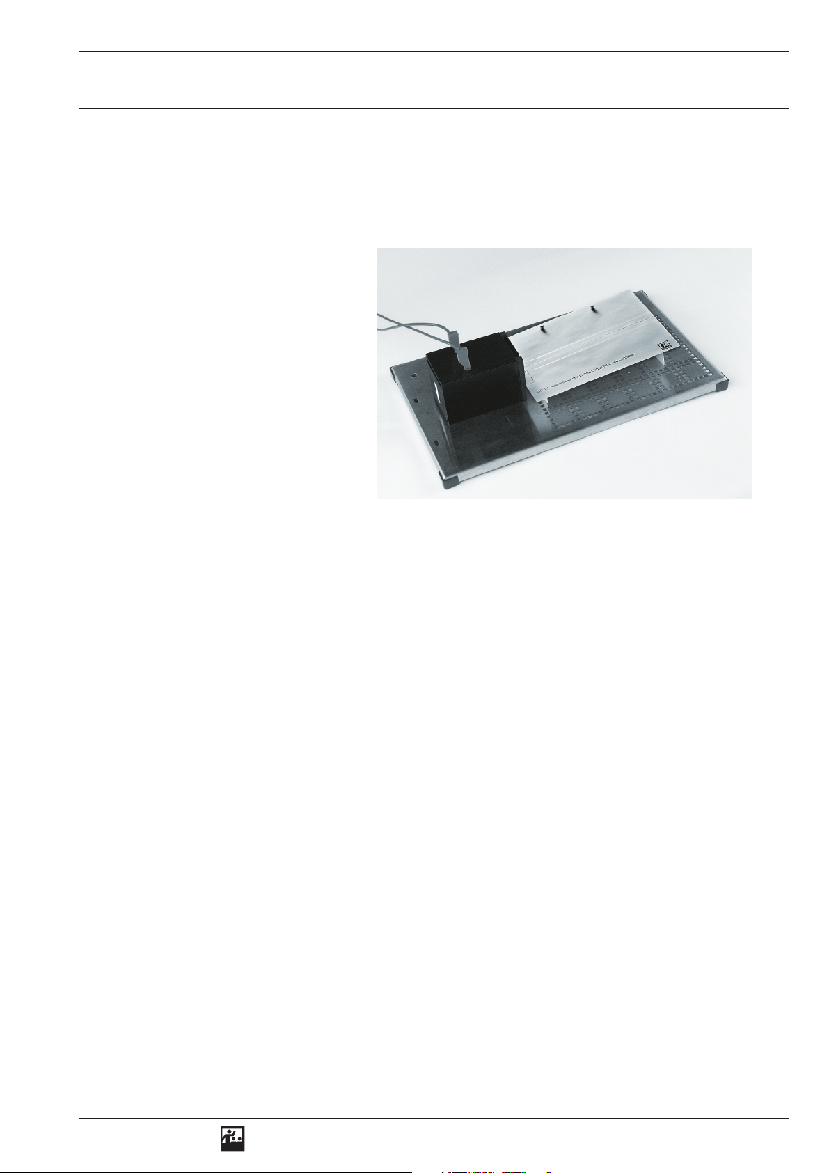
1 SEG - OP 1.1Diffusion of Light, Pencil of Rays and Light Beam
Exercise
Examine how light diffuses!
What do we need?
1 Optical lamp
with power supply unit
1 Base plate
1 Three-slot aperture
1 Mask
Conducting the experiment
1. Attach the mask to the base plate!
Reproduction is allowed only for use with ELWE-equipment.
2. Place the optical lamp on the left side of the base plate, so that the light emerges conically to the
right!
3. Sketch the edges of the beam of light on the mask!
4. Hatch the illuminated area with a coloured pen!
5. Insert the three-slot aperture into the aperture holder!
6. Draw the three narrow beams of light as lines!
ELWE
Physical experiments for education in natural science and engineering
Page 6

2 SEG - OP 1.1Diffusion of Light, Pencil of Rays and Light Beam
Analysis
Sketch
Result
1. The light diffuses . . . . . . . . . . . . . . . . . . . . . . . . . . . . . . . . . . . . . . . . . . . . . . . . . . . . . . . . . . . . . . . .
2. A very narrow beam of light is called a . . . . . . . . . . . . . . . . . . . . . . . . . . . . . . . . . . . . . . . . . . . . . . .
Reproduction is allowed only for use with ELWE-equipment.
ELWE
Physical experiments for education in natural science and engineering
Page 7

1 SEG - OP 1.2Light Transmission
Exercise
Examine how materials react when exposed to light!
What do we need?
1 Optical lamp
with power supply unit
1 Base plate
1 Screen
1 Plexiglass pane
1 Mask
additionally required:
1 Glass pane
1 Transparent foil
1 Transparent paper
1 Mat glass pane
1 Book
Conducting the experiment
Reproduction is allowed only for use with ELWE-equipment.
1stexperiment
1. Attach the mask to the base plate!
2. Place the optical lamp on the left side of the base plate, so that the light emerges conically to the
right!
3. Place the screen onto the base plate as marked on the mask!
4. Put the transparent plate in front of the light source and examine how much light is transmitted!
5. Use further materials and examine how they transmit light!
6. Arrange the materials and record them in table 1 according to how they react!
nd
2
experiment
1. Cut out six equal squares of transparent paper (5 cm x 5 cm each)! Draw a match-stick man on
one square!
2. Insert the square with the match-stick man into the aperture holder!
ELWE
Physical experiments for education in natural science and engineering
Page 8
2 SEG - OP 1.2Light Transmission
3. Look into the light and check whether you can still see the match-stick man!
4. Put two, then three, then four and finally five squares of transparent paper in front of the match-stick man!
5. Check how much light is transmitted! Enter the test results in table 2!
Analysis
Table 1 Light transmission
Light is transmitted Some light is transmitted No light is transmitted
Table 2 Light transmission as a function of thickness
Light transmission
Number of paper squares
(very good / good / less satisfactory /
little / none)
Result
1. There are materials that . . . . . . . . . . . . . . . . . . . . . . . . . . . . . . . . . . . . . . . . . . . . . . . . . . . . . . .light,
they are called . . . . . . . . . . . . . . . . . . . . . . . . . . . . . . . . . . . . . . . . . . . . . . . . . . . . . . . . . . . . . . . . . .
2. There are materials that . . . . . . . . . . . . . . . . . . . . . . . . . . . . . . . . . . . . . . . . . . . . . . . . . . . . . . . . . .,
they are called . . . . . . . . . . . . . . . . . . . . . . . . . . . . . . . . . . . . . . . . . . . . . . . . . . . . . . . . . . . . . . . . . .
Reproduction is allowed only for use with ELWE-equipment.
3. There are materials that . . . . . . . . . . . . . . . . . . . . . . . . . . . . . . . . . . . . . . . . . . . . . . . . . . . . . . . . . .,
they are called . . . . . . . . . . . . . . . . . . . . . . . . . . . . . . . . . . . . . . . . . . . . . . . . . . . . . . . . . . . . . . . . . .
4. The translucence of light is a function of . . . . . . . . . . . . . . . . . . . . . . . . . . . . . . . . . . . . . . . . . . . . .
. . . . . . . . . . . . . . . . . . . . . . . . . . . . . . . . . . . . . . . . . . . . . . . . . . . . . . . . . . . . . . . . . . . . . . . . . . . . . .
ELWE
Physical experiments for education in natural science and engineering
Page 9
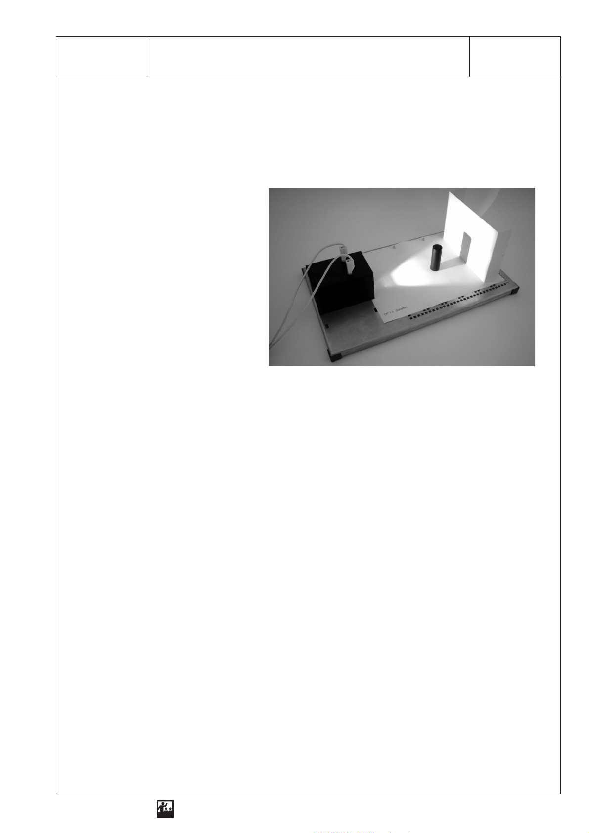
1 SEG - OP 1.3Shadows
Exercise
Examine how shadows develop and under what conditions shadows are large or small!
What do we need?
1 Optical lamp
with power supply unit
1 Base plate
1 Shadow object
1 Screen
1 Mask
additionally required:
3 Sheets of white paper, 17 cm x 13 cm
1 Eraser
1 Sharpener
1 Adhesive tape
1 Ruler
Conducting the experiment
1stexperiment
Reproduction is allowed only for use with ELWE-equipment.
1. Attach the mask to the base plate!
2. Place the optical lamp on the left side of the base plate, so that the light emerges conically to the
right!
3. Place the screen on the right side of the base plate!
4. Put the shadow object right in front of the screen as marked on the mask!
5. Measure the height and width of the shadow object and the height and width of the shadow! Enter
the values in table 1!
6. Slowly move the shadow object a few centimetres towards the lamp and observe how the shadow
changes! Discribe the result!
7. Put the shadow object back in front of the screen! Now hold the screen at different distances to the
shadow object and observe how the shadow changes! Discribe the result!
ELWE
Physical experiments for education in natural science and engineering
Page 10
2 SEG - OP 1.3Shadows
2ndexperiment
1. Attach a piece of white paper to the screen!
2. Put the screen back to the end of the base plate and the cylinder as close to the screen as possible!
3. Sketch the shape of the shadow on the white paper!
4. First place the sharpener and then the eraser on the same spot and sketch each shape of the
shadow on a piece of white paper! Compare the shape of the shadows with the shape of the object!
Analysis
Table
Height of the
shadow object
Length of the
shadow object
Height of the shadow Length of the shadow
Observations when the shadow object is moved towards the optical light:
. . . . . . . . . . . . . . . . . . . . . . . . . . . . . . . . . . . . . . . . . . . . . . . . . . . . . . . . . . . . . . . . . . . . . . . . . . . . . . . . .
. . . . . . . . . . . . . . . . . . . . . . . . . . . . . . . . . . . . . . . . . . . . . . . . . . . . . . . . . . . . . . . . . . . . . . . . . . . . . . . . .
Observations when the screen is moved away from the shadow object:
. . . . . . . . . . . . . . . . . . . . . . . . . . . . . . . . . . . . . . . . . . . . . . . . . . . . . . . . . . . . . . . . . . . . . . . . . . . . . . . . .
. . . . . . . . . . . . . . . . . . . . . . . . . . . . . . . . . . . . . . . . . . . . . . . . . . . . . . . . . . . . . . . . . . . . . . . . . . . . . . . . .
Result
Reproduction is allowed only for use with ELWE-equipment.
1. Behind a . . . . . . . . . . . . . . . . . . . . . . . . object a . . . . . . . . . . . . . . . . . . . . . . . . . . . . . . . develops.
2. The shadow increases, when . . . . . . . . . . . . . . . . . . . . . . . . . . . . . . . . . . . . . . . . . . . . . . . . . . . . . .
3. The dimension of the shadow depends on . . . . . . . . . . . . . . . . . . . . . . . . . . . . . . . . . . . . . . . . . . . .
. . . . . . . . . . . . . . . . . . . . . . . . . . . . . . . . . . . . . . . . . . . . . . . . . . . . . . . . . . . . . . . . . . . . . . . . . . . . . .
4. The shape of the shadow depends on. . . . . . . . . . . . . . . . . . . . . . . . . . . . . . . . . . . . . . . . . . . . . . . .
. . . . . . . . . . . . . . . . . . . . . . . . . . . . . . . . . . . . . . . . . . . . . . . . . . . . . . . . . . . . . . . . . . . . . . . . . . . . . .
ELWE
Physical experiments for education in natural science and engineering
Page 11
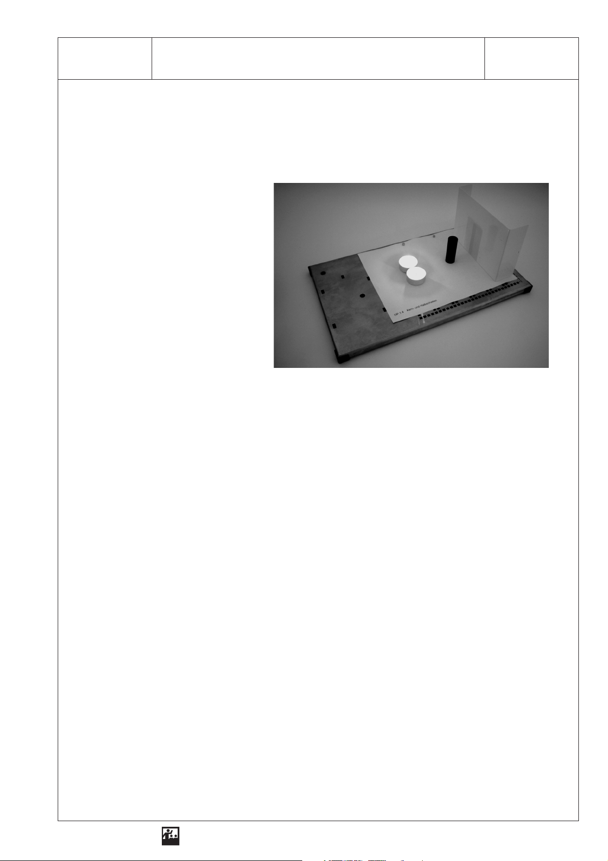
1 SEG - OP 1.4Half-Shadow and Complete Shadow
Exercise
Examine the shape of the shadow when the object is illuminated by two light sources!
What do we need?
1 Base plate
1 Screen
2 Tea lights
1 Shadow object
1 Mask
additionally required:
1 Sheet of white paper, 17 cm x 13 cm
Conducting the experiment
1. Attach the mask to the base plate!
2. Put two tea lights and the shadow object onto the base plate as marked on the mask! Attach the
white paper to the screen and place the screen on the right side of the base plate!
Reproduction is allowed only for use with ELWE-equipment.
3. Carefully light the first tea light! Observe and draw the shadow behind the shadow object! Use the
given data for sketch 1!
4. Mark in sketch 1 where a shadow develops when just one tea light is lit!
5. Light the second tea light! Observe the shadow behind the shadow object!
6. Cross all shadows with different shades of grey on the paper attached to the screen!
7. Construct the beam development! Use the given data for sketch 2!
ELWE
Physical experiments for education in natural science and engineering
Page 12
2 SEG - OP 1.4Half-Shadow and Complete Shadow
Analysis
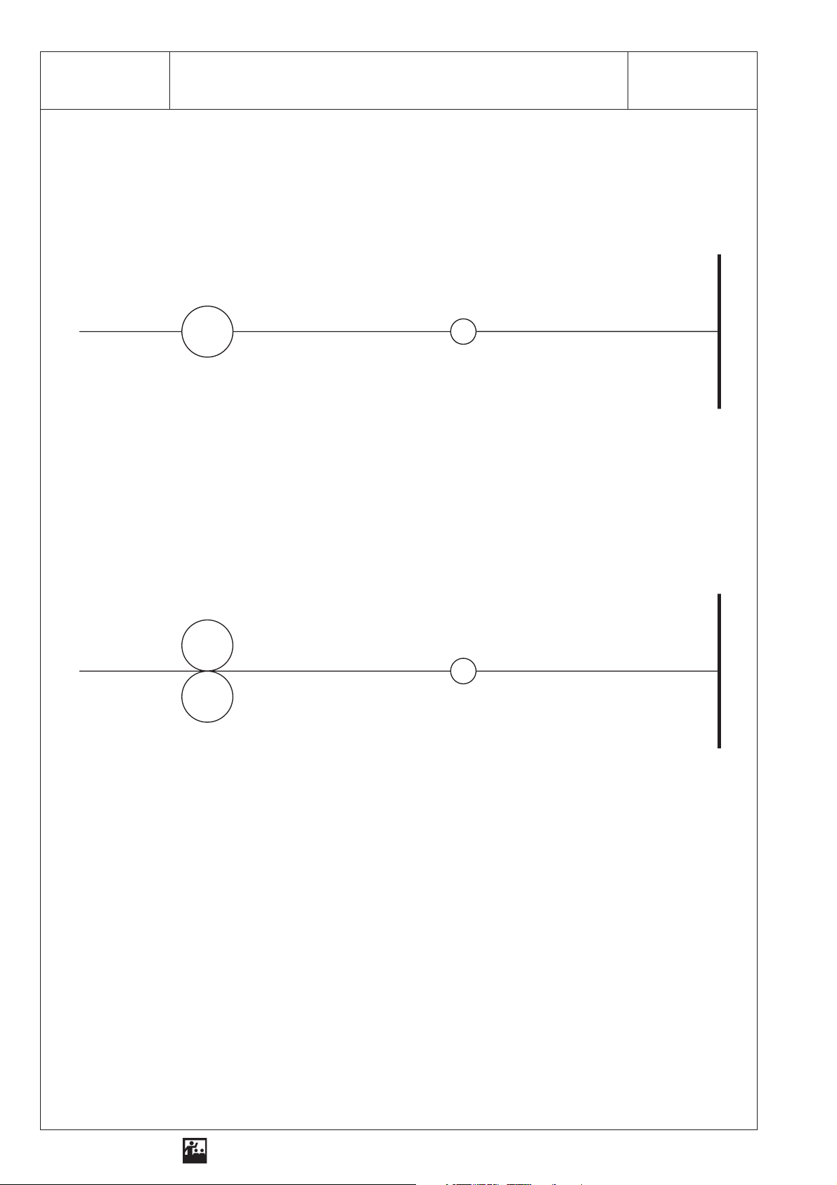
Sketch 1
Shadow when one tea light is lit:
Tea light
Sketch 2
Forming a shadow image with two tea lights:
Tea lights Cylinder
Cylinder
Screen
Screen
Reproduction is allowed only for use with ELWE-equipment.
Result
1. Features of the shadow when one tea light is lit:
. . . . . . . . . . . . . . . . . . . . . . . . . . . . . . . . . . . . . . . . . . . . . . . . . . . . . . . . . . . . . . . . . . . . . . . . . . . . . .
. . . . . . . . . . . . . . . . . . . . . . . . . . . . . . . . . . . . . . . . . . . . . . . . . . . . . . . . . . . . . . . . . . . . . . . . . . . . . .
2. Features of the shadow when both tea lights are lit:
. . . . . . . . . . . . . . . . . . . . . . . . . . . . . . . . . . . . . . . . . . . . . . . . . . . . . . . . . . . . . . . . . . . . . . . . . . . . . .
. . . . . . . . . . . . . . . . . . . . . . . . . . . . . . . . . . . . . . . . . . . . . . . . . . . . . . . . . . . . . . . . . . . . . . . . . . . . . .
. . . . . . . . . . . . . . . . . . . . . . . . . . . . . . . . . . . . . . . . . . . . . . . . . . . . . . . . . . . . . . . . . . . . . . . . . . . . . .
ELWE
Physical experiments for education in natural science and engineering
Page 13

3 SEG - OP 1.4Half-Shadow and Complete Shadow
3. When the shadow object is illuminated by two light sources, . . . . . . . . . . . . . . . . . . . . . . . . . . . . . .
. . . . . . . . . . . . . . . . . . . . . . . . . . . . . . . . . . . . . . . . . . . . . . . . . . . . . . . . . . . . . . . . . . . . . . . . . . . . . .
. . . . . . . . . . . . . . . . . . . . . . . . . . . . . . . . . . . . . . . . . . . . . . . . . . . . . . . . . . . . . . . . . . . . . . . . . . . . . .
develops behind the shadow object.
Reproduction is allowed only for use with ELWE-equipment.
ELWE
Physical experiments for education in natural science and engineering
Page 14

Page 15
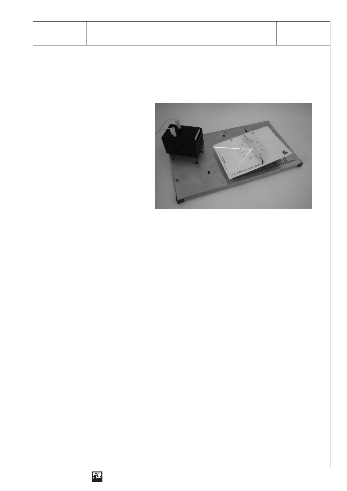
1 SEG - OP 2.1Reflection on a Plane Mirror
Exercise
Examine the incident light on a plane reflecting surface!
What do we need?
1 Optical lamp
with power supply unit
1 Base plate
1 Universal mirror
1 Single-slot aperture
1 Screen
1 Mask
additionally required:
1 Triangle with right angle
1 Coloured pen
Conducting the experiment
1. Attach the mask to the screen!
2. Place the optical lamp on the left side of the base plate, so that light emerges parallel to the right!
Reproduction is allowed only for use with ELWE-equipment.
3. Place the screen in front of the optical lamp!
4. Insert the single-slot aperture into the aperture holder!
5. Place the universal mirror on the screen as marked on the mask!
6.
Adjust an angle of incidence α = 30° by changing the position of the lamp! Draw the incident and
the reflected beam on the mask!
7. Draw the axis of incidence! Measure the angle of incidence and the angle of reflection! Enter the
values in the table!
8. Turn the lamp a little and adjust a different angle of incidence! Draw the incident and the reflected
beam. Draw the axis of incidence and measure the angle of incidence and the angle of reflection!
Use a coloured pen! Enter the measured values in the table!
9. Turn the lamp a little further! Again draw the beams and the axis of incidence and measure the angles of incidence and reflection!
10. Compare the angle of incidence to the angle of reflection and describe the result!
11. Name practical applications for the use of reflection! Give one example!
ELWE
Physical experiments for education in natural science and engineering
Page 16
2 SEG - OP 2.1Reflection on a Plane Mirror
Analysis
Table
Angle of incidence α Angle of reflection α‘
Result
1. The law of reflection says:
. . . . . . . . . . . . . . . . . . . . . . . . . . . . . . . . . . . . . . . . . . . . . . . . . . . . . . . . . . . . . . . . . . . . . . . . . . . . . .
. . . . . . . . . . . . . . . . . . . . . . . . . . . . . . . . . . . . . . . . . . . . . . . . . . . . . . . . . . . . . . . . . . . . . . . . . . . . . .
. . . . . . . . . . . . . . . . . . . . . . . . . . . . . . . . . . . . . . . . . . . . . . . . . . . . . . . . . . . . . . . . . . . . . . . . . . . . . .
2. Practical applications for the use of reflection:
. . . . . . . . . . . . . . . . . . . . . . . . . . . . . . . . . . . . . . . . . . . . . . . . . . . . . . . . . . . . . . . . . . . . . . . . . . . . . .
. . . . . . . . . . . . . . . . . . . . . . . . . . . . . . . . . . . . . . . . . . . . . . . . . . . . . . . . . . . . . . . . . . . . . . . . . . . . . .
. . . . . . . . . . . . . . . . . . . . . . . . . . . . . . . . . . . . . . . . . . . . . . . . . . . . . . . . . . . . . . . . . . . . . . . . . . . . . .
3. Explanation of an example:
. . . . . . . . . . . . . . . . . . . . . . . . . . . . . . . . . . . . . . . . . . . . . . . . . . . . . . . . . . . . . . . . . . . . . . . . . . . . . .
. . . . . . . . . . . . . . . . . . . . . . . . . . . . . . . . . . . . . . . . . . . . . . . . . . . . . . . . . . . . . . . . . . . . . . . . . . . . . .
Reproduction is allowed only for use with ELWE-equipment.
. . . . . . . . . . . . . . . . . . . . . . . . . . . . . . . . . . . . . . . . . . . . . . . . . . . . . . . . . . . . . . . . . . . . . . . . . . . . . .
ELWE
Physical experiments for education in natural science and engineering
Page 17

1 SEG - OP 2.2Collecting Light with a Concave Mirror
Exercise
Examine the incident light on a bent reflecting surface (concave mirror)!
What do we need?
1 Optical lamp
with power supply unit
1 Base plate
1 Universal mirror
1 Screen
1 Three-slot aperture
1 Mask
additionally required:
1 Ruler
1 Coloured pen
Conducting the experiment
1. Attach the mask to the screen!
Reproduction is allowed only for use with ELWE-equipment.
2. Place the optical lamp on the left side of the base plate, so that the light emerges parallel to the
right!
3. Place the screen in front of the optical lamp!
4. Place the mirror on the screen and bend it as marked on the mask!
5. Insert the three-slot aperture into the aperture holder!
6. Observe the beam of light after hitting the concave mirror! Draw the beam of light on the mask!
7. Determine the distance between concave mirror and focal point and therefore the focal length!
8. Draw five incident beams of light and the respective reflected beams of light (sketch)!
9. Change the curvature of the concave mirror! Use a coloured pen to draw the concave mirror with
the changed curvature on the mask! Repeat exercises 6 and 7!
ELWE
Physical experiments for education in natural science and engineering
Page 18
2 SEG - OP 2.2Collecting Light with a Concave Mirror
Analysis
Radius of curvature of the concave mirror: . . . . . . . . . . . . . .
Focal length of the concave mirror: . . . . . . . . . . . . . . . . . . . .
Five incident beams of light and the respective reflected beams:
Sketch
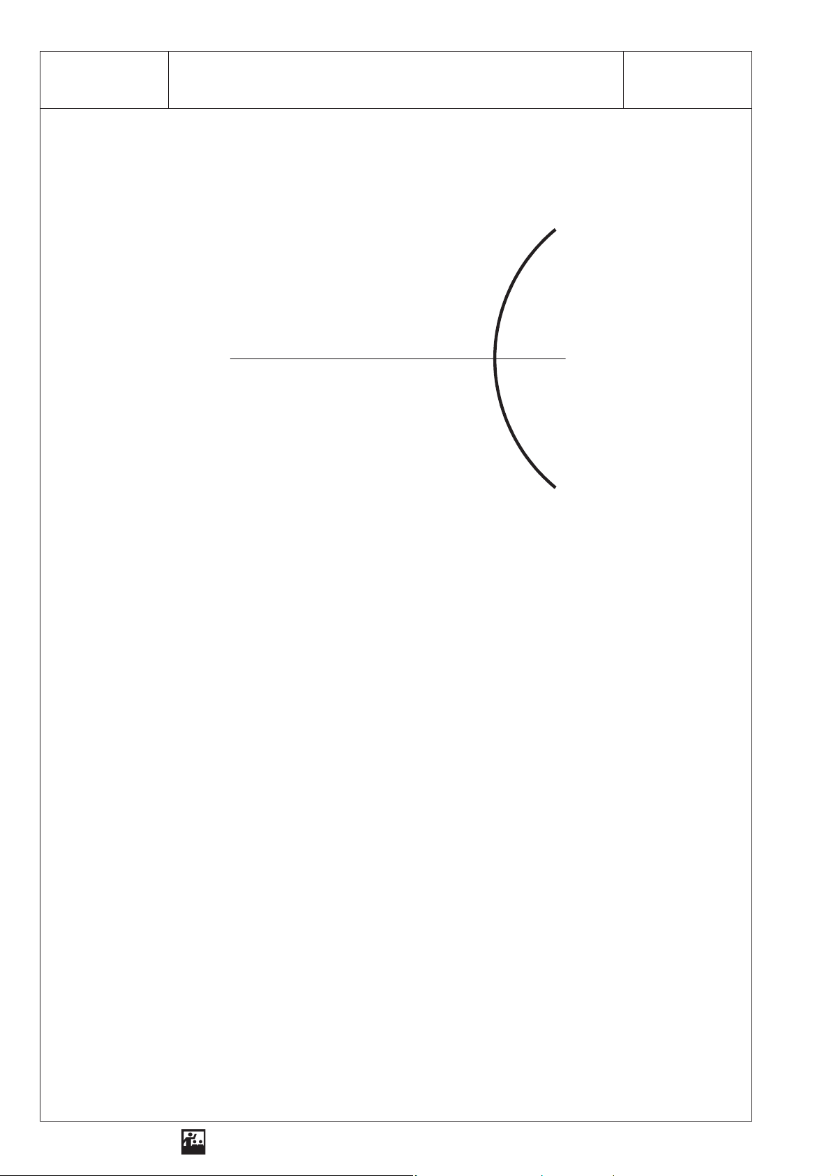
optical axis
M
concave mirror
r
= 6.5 cm)
(
Result
1. On a concave mirror light is . . . . . . . . . . . . . . . . . . . . . . . . . . . . . . . . . . . . . . . . . . . . . . . . . . . . . . .
2. Incident light parallel to the optical axis is . . . . . . . . . . . . . . . . . . . . . . . . . . . . . . . . . . . . . . . . . . . . .
. . . . . . . . . . . . . . . . . . . . . . . . . . . . . . . . . . . . . . . . . . . . . . . . . . . . . . . . . . . . . . . . . . after reflection.
3. The curvature of the concave mirror affects . . . . . . . . . . . . . . . . . . . . . . . . . . . . . . . . . . . . . . . . . . .
. . . . . . . . . . . . . . . . . . . . . . . . . . . . . . . . . . . . . . . . . . . . . . . . . . . . . . . . . . . . . . . . . . . . . . . . . . . . . .
4. Three beams of light after reflection:
Reproduction is allowed only for use with ELWE-equipment.
A beam of light parallel to the optical axis is . . . . . . . . . . . . . . . . . . . . . . . . . . . . . . . . . . . . . . . . . . .
. . . . . . . . . . . . . . . . . . . . . . . . . . . . . . . . . . . . . . . . . . . . . . . . . . . . . . . . . . . . . . . . . . . . . . . . . . . . . .
. . . . . . . . . . . . . . . . . . . . . . . . . . . . . . . . . . . . . . . . . . . . . . . . . . . . . . . . . . . . . . . . . . . . . . . . . . . . . .
5. The focal length of the concave mirror depends upon. . . . . . . . . . . . . . . . . . . . . . . . . . . . . . . . . . . .
6. When the curvature increases, the . . . . . . . . . . . . . . . . . . . . . . . . . . . . . . . . . . . . . . . . . . . . . . . . . .
ELWE
Physical experiments for education in natural science and engineering
Page 19
1 SEG - OP 2.3Reflection and Beam Paths on a Concave Mirror
Exercise
Examine how selected beams of light are reflected on a concave mirror!
What do we need?
1 Optical lamp with power supply unit
1 Base plate
1 Universal mirror
1 Screen
1 Single-slot aperture
1 Three-slot aperture
1 Mask
additionally required:
1 Compasses
1 Ruler
Conducting the experiment
1. Attach the mask to the screen!
2. Place the optical lamp on the left side of the base plate, so that the light emerges parallel to the
Reproduction is allowed only for use with ELWE-equipment.
right!
3. Place the screen in front of the optical lamp!
4. Insert the three-slot aperture into the aperture holder!
5. Place the universal mirror on the screen and bend it as marked on the mask!
6. Determine the focal point with three parallel beams! Mark the focal point! Then draw the centre of
the concave mirror! Enter the values for the focal length and the radius of the concave mirror in the
table!
7. Replace the three-slot aperture by a one-slot aperture!
8. Generate a parallel beam close to the axis! Change the position of the optical lamp! Observe the
parallel incident beam of light after it hit the concave mirror! Draw the incident and the reflected
beam of light!
9. Repeat the experiment with a focal beam!
10. Repeat the experiment with a centre point beam!
11. Name possible applications for concave mirrors! Explain one application!
ELWE
Physical experiments for education in natural science and engineering
Page 20
2 SEG - OP 2.3Reflection and Beam Paths on a Concave Mirror
Analysis
Table
Focal lengthfof the
concave mirror in cm
Radiusrof the
concave mirror in cm
Construct the concave mirror with the aid of the measured values and with the compass!
Draw the test results into your constructed concave mirror!
1. Parallel beam:
2. Centre point beam:
3. Focal beam:
Result
1. On a concave mirror light is . . . . . . . . . . . . . . . . . . . . . . . . . . . . . . . . . . . . . . . . . . . . . . . . . . . . . . . .
2. Parallel beams are . . . . . . . . . . . . . . . . . . . .as . . . . . . . . . . . . . . . . . . . . . . . . . . . . . . . . . . . . . . . . .
3. Focal beams are . . . . . . . . . . . . . . . . . . . . . as . . . . . . . . . . . . . . . . . . . . . . . . . . . . . . . . . . . . . . . . .
4. Centre point beams are . . . . . . . . . . . . . . . . as . . . . . . . . . . . . . . . . . . . . . . . . . . . . . . . . . . . . . . . .
5. Concave mirrors are used in the following technical appliances:
. . . . . . . . . . . . . . . . . . . . . . . . . . . . . . . . . . . . . . . . . . . . . . . . . . . . . . . . . . . . . . . . . . . . . . . . . . . . . .
. . . . . . . . . . . . . . . . . . . . . . . . . . . . . . . . . . . . . . . . . . . . . . . . . . . . . . . . . . . . . . . . . . . . . . . . . . . . . .
6. Description of an example:
. . . . . . . . . . . . . . . . . . . . . . . . . . . . . . . . . . . . . . . . . . . . . . . . . . . . . . . . . . . . . . . . . . . . . . . . . . . . . .
. . . . . . . . . . . . . . . . . . . . . . . . . . . . . . . . . . . . . . . . . . . . . . . . . . . . . . . . . . . . . . . . . . . . . . . . . . . . . .
Reproduction is allowed only for use with ELWE-equipment.
ELWE
Physical experiments for education in natural science and engineering
Page 21
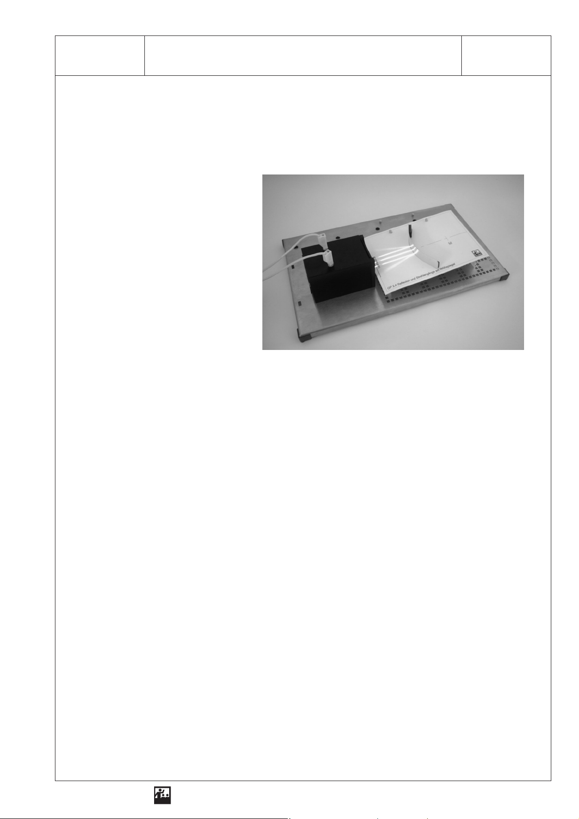
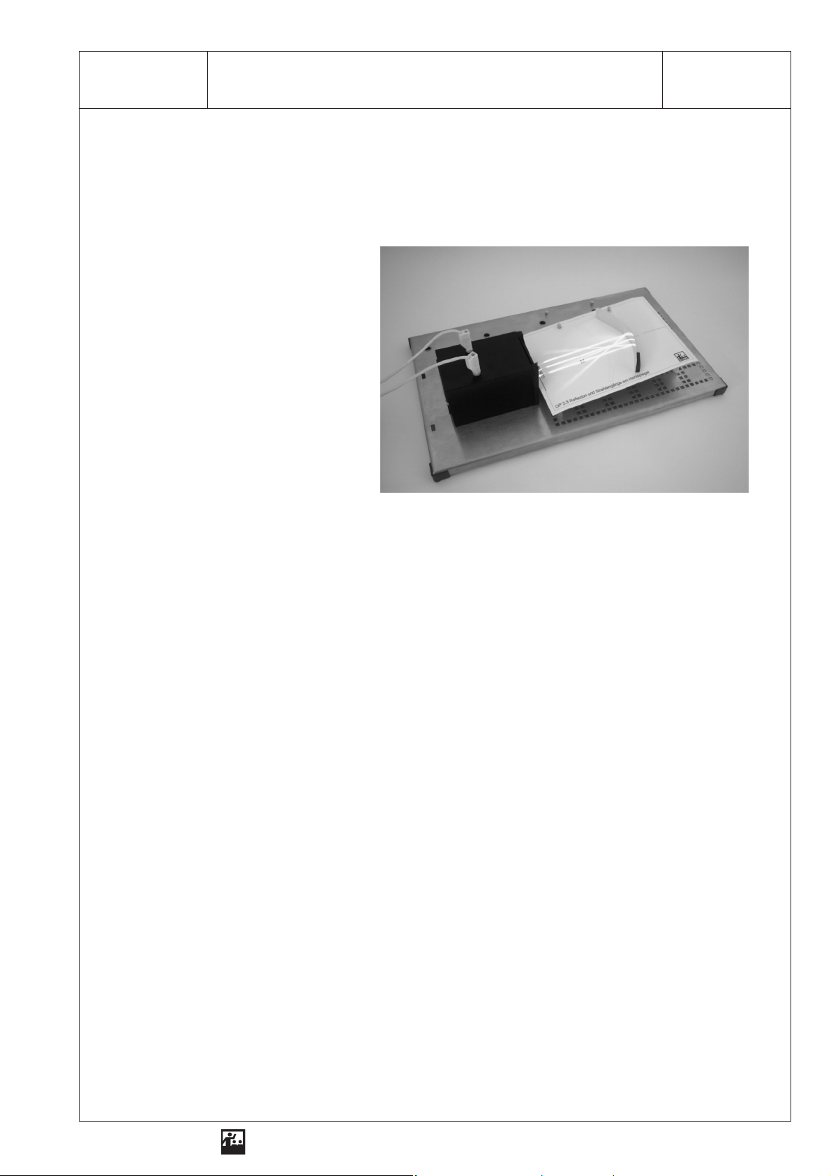
1 SEG - OP 2.4Reflection and Beam Paths on a Convex Mirror
Exercise
Examine how the light is reflected on the convex mirror!
What do we need?
1 Optical lamp
with power supply unit
1 Base plate
1 Universal mirror
1 Three-slot aperture
1 Mask
additionally required:
1 Compasses
1 Ruler
Conducting the experiment
1. Attach the mask to the screen!
Reproduction is allowed only for use with ELWE-equipment.
2. Place the optical lamp on the left side of the base plate, so that the light emerges parallel to the
right!
3. Place the screen in front of the optical lamp! Insert the three-slot aperture into the aperture holder!
4. Place the universal mirror on the screen and bend it as marked on the mask!
5. Mark the position of the focal point. Mark it “F”!
6. Record your observations on the three parallel incident beams of light after the reflection! Draw the
beams on the mask! Mark the point where the rear projections of the reflected beams cross the optical axis!
7. Bend the convex mirror as sketched! Transmit the beams onto the sketch!
8. Name practical applications for the use of convex mirrors!
ELWE
Physical experiments for education in natural science and engineering
Page 22
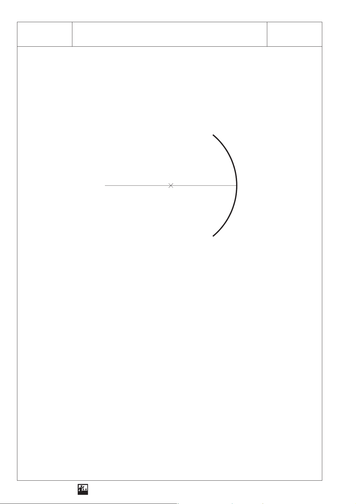
2 SEG - OP 2.4Reflection and Beam Paths on a Convex Mirror
Analysis
Sketch
Result
incident beams of light:
optical axis
reflected beams of light:
convex mirror
r
= 6.5 cm)
(
1. On a convex mirror light is . . . . . . . . . . . . . . . . . . . . . . . . . . . . . . . . . . . . . . . . . . . . . . . . . . . . . . . . .
2. On a convex mirror the parallel beams are . . . . . . . . . . . . . . . . . . . . . . . . . . . . . . . . . . . . . . . . . . . .
as . . . . . . . . . . . . . . . . . . . . . . . . . . . . . . . . . . . . . . . . . . . . . . . . . . . . . . . . . . . . . . . . . . . . . . . . . . . .
3. Convex mirrors are used as: . . . . . . . . . . . . . . . . . . . . . . . . . . . . . . . . . . . . . . . . . . . . . . . . . . . . . . .
. . . . . . . . . . . . . . . . . . . . . . . . . . . . . . . . . . . . . . . . . . . . . . . . . . . . . . . . . . . . . . . . . . . . . . . . . . . . . .
. . . . . . . . . . . . . . . . . . . . . . . . . . . . . . . . . . . . . . . . . . . . . . . . . . . . . . . . . . . . . . . . . . . . . . . . . . . . . .
. . . . . . . . . . . . . . . . . . . . . . . . . . . . . . . . . . . . . . . . . . . . . . . . . . . . . . . . . . . . . . . . . . . . . . . . . . . . . .
Reproduction is allowed only for use with ELWE-equipment.
ELWE
Physical experiments for education in natural science and engineering
Page 23
1 SEG - OP 2.5Images on a Plane Mirror
Exercise
Examine the features of images on a plane mirror!
What do we need?
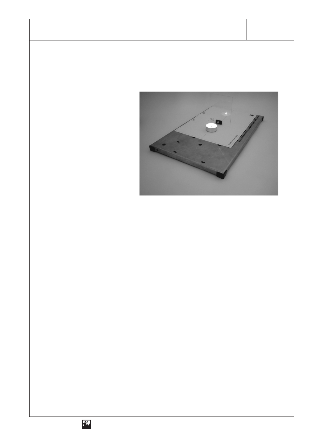
1 Base plate
1 Plexiglass plate
2 Tea lights
1 Mask
additionally required:
1 Ruler
Conducting the experiment
1. Attach the mask to the base plate!
2. Place the Plexiglas plate onto the centre of the base plate as marked on the mask!
Reproduction is allowed only for use with ELWE-equipment.
3. Put a tea light in front of the plate (mask)! Observe the mirror image of the tea light!
4. Light the tea light and observe the mirror image! Record the features of the mirror image of the
burning tea light!
5. Place the second non-burning tea light behind the Plexiglas plate where you see the mirror image!
Record your observations and draw the position of the tea light on the mask!
6. Now move the burning tea light in front of the Plexiglass plate approx. 3 cm to the right! Observe
the mirror image of the burning tea light!
7. Make a note of what you have to do to see the mirror image of the burning tea light at the same
place as the non-burning tea light behind the pane!
8. Determine the distance of the tea light in front of the Plexiglas plate and behind the Plexiglas plate!
Enter the measured values in the table! Mark the positions of the first and the second candle on
the mask!
9. Name features of the mirror image!
ELWE
Physical experiments for education in natural science and engineering
Page 24
2 SEG - OP 2.5Images on a Plane Mirror
Analysis
Table
Features
Measured values
Height of the two tea lights
Height of the mirror image of the non-burning tea light
Distance between Plexiglas plate and front tea light
Distance between Plexiglas plate and rear tea light
Changed position of the front tea light
Changed position of the rear tea light
Result
1. On the plane mirror . . . . . . . . . . . . . . . . . . . . . . . . . . . . . . . . . . . . . . . . . . . . . . . . . . . . . . develops.
2. The images on a plane mirror have the following features:
. . . . . . . . . . . . . . . . . . . . . . . . . . . . . . . . . . . . . . . . . . . . . . . . . . . . . . . . . . . . . . . . . . . . . . . . . . . . . .
. . . . . . . . . . . . . . . . . . . . . . . . . . . . . . . . . . . . . . . . . . . . . . . . . . . . . . . . . . . . . . . . . . . . . . . . . . . . . .
. . . . . . . . . . . . . . . . . . . . . . . . . . . . . . . . . . . . . . . . . . . . . . . . . . . . . . . . . . . . . . . . . . . . . . . . . . . . . .
. . . . . . . . . . . . . . . . . . . . . . . . . . . . . . . . . . . . . . . . . . . . . . . . . . . . . . . . . . . . . . . . . . . . . . . . . . . . . .
Reproduction is allowed only for use with ELWE-equipment.
ELWE
Physical experiments for education in natural science and engineering
Page 25
1 SEG - OP 3.1Refraction for the Transition from Air to Glass
Exercise
Examine the way light reacts at the transition from air to glass!
What do we need?
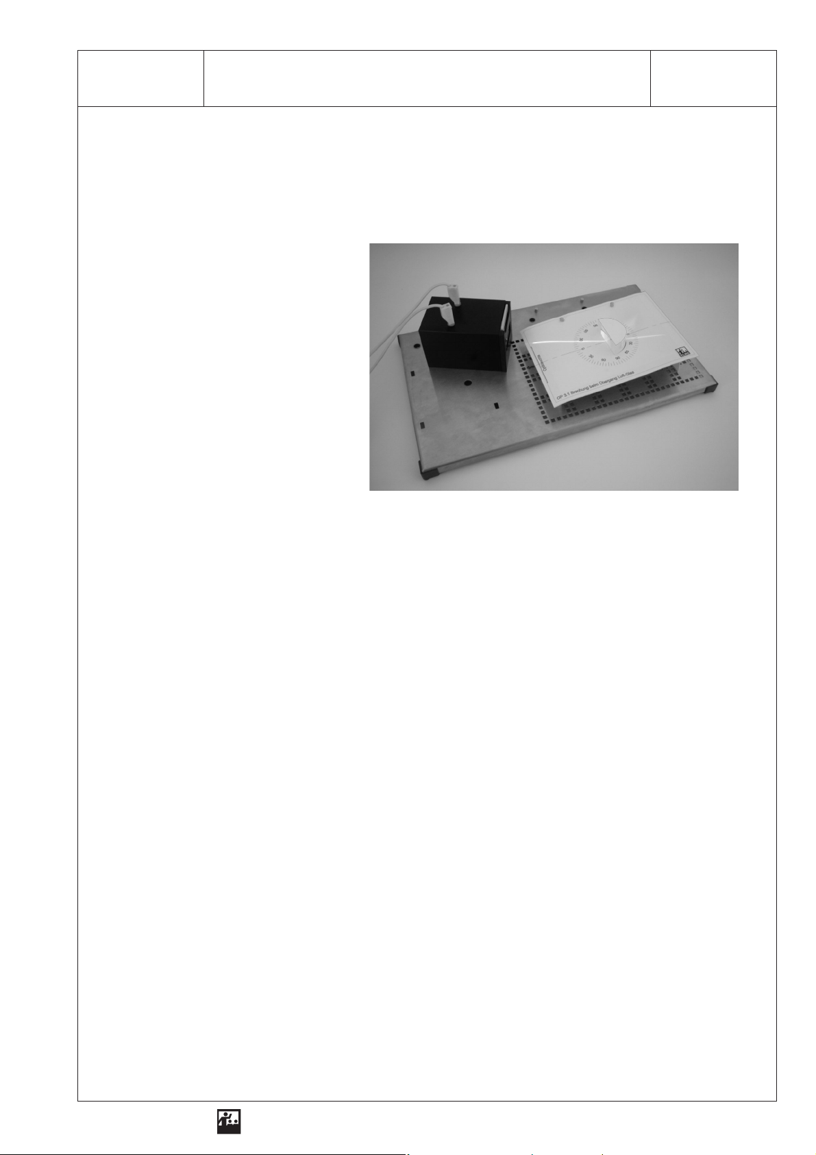
1 Optical lamp
with power supply unit
1 Base plate
1 Screen
1 Semicircular glass object
(flat design)
1 Single-slot aperture
1 Mask
Conducting the experiment
1. Attach the mask to the screen!
2. Place the optical lamp on the left side of the base plate, so that the light emerges parallel to the
right!
3. Place the screen in front of the optical lamp!
Reproduction is allowed only for use with ELWE-equipment.
4. Place the semicircular glass object onto the middle of the screen as marked on the mask!
5. Insert the single-slot aperture into the aperture holder on the optical lamp!
6. First, the light should hit the plane on the glass object along the optical axis! Observe the light
when it passes the glass object1! Record your observations in the table!
7. Change the position of the optical lamp, so that the light hits the centre of the glass plate at an angle! Observe and record your observation!
8. Change the position of the optical lamp twice, so that the light hits the semicircular glass object at
different angles! Observe and record your observations in the table!
9. If the path of light is reversible, it is possible to set up a statement on the way the light reacts at the
transition from glass to air! Formulate the statement!
ELWE
Physical experiments for education in natural science and engineering
Page 26
2 SEG - OP 3.1Refraction for the Transition from Air to Glass
Analysis
Table
Angle of incidence α
of the light
Observations for the transition from air to glass
Result
1. When transmitted from air to glass, the light . . . . . . . . . . . . . . . . . . . . . . . . . . . . . . . . . . . . . . . . . . .
. . . . . . . . . . . . . . . . . . . . . . . . . . . . . . . . . . . . . . . . . . . . . . . . . . . . . . . . . with angles larger than 0°.
2. When the . . . . . . . . . . . . . . . . . . . . . . . . . . . . increases, the . . . . . . . . . . . . . . . . . . . . . . . . . . . . . .
. . . . . . . . . . . . . . . . . . . . . . . . . . . . . . . . . . . . . . . . . . . . . . . . . . . . . . . . . . . . . . . . . . . . . . . . . . . . . .
3. When transmitted from glass to air, the light . . . . . . . . . . . . . . . . . . . . . . . . . . . . . . . . . . . . . . . . . . .
. . . . . . . . . . . . . . . . . . . . . . . . . . . . . . . . . . . . . . . . . . . . . . . . . . . . . . . . . . . . . . . . . . . . . . . . . . . . . .
. . . . . . . . . . . . . . . . . . . . . . . . . . . . . . . . . . . . . . . . . . . . . . . . . . . . . . . . . . . . . . . . . . . . . . . . . . . . . .
Reproduction is allowed only for use with ELWE-equipment.
ELWE
Physical experiments for education in natural science and engineering
Page 27

1 SEG - OP 3.2Law of Refraction, Determining the Refractive Index
Exercise
Examine how the light reacts at the transition from air to glass!
What do we need?
1 Optical lamp
with power supply unit
1 Base plate
1 Screen
1 Semicircular glass object
(flat design)
1 Single-slot aperture
1 Mask
Conducting the experiment
1. Attach the mask to the screen!
2. Place the optical lamp on the left side of the base plate, so that the light emerges parallel to the
right!
3. Place the screen in front of the optical lamp!
Reproduction is allowed only for use with ELWE-equipment.
4. Place the semicircular glass object in the middle as marked on the mask!
5. Insert the single-slot aperture into the aperture holder!
6. Complete the column titles in the table!
7.
Adjust an angle of incidence of α = 20° by changing the position of the lamp and determine the angle of refraction!
8.
Repeat the experiment with the following angles of incidence: α = 30°, 40°, 50°, 60°, 70°!
Enter the values in the table!
9. Determine the sinus for each angle and calculate the quotient for the sinuses of the angle of incidence and the angle of refraction!
10. Formulate the law of refraction for the transition of the light from air to glass!
11. Calculate the quotient from column 3 and column 4 and enter the value in column 5 of the table!
What feature is characterised by the quotient?
ELWE
Physical experiments for education in natural science and engineering
Page 28

2 SEG - OP 3.2Law of Refraction, Determining the Refractive Index
Analysis
Table
Angle of incidence α Angle of refraction β
Result
1. When transmitted from air to glass, the light . . . . . . . . . . . . . . . . . . . . . . . . . . . . . . . . . . . . . . . . . . .
2. The law of refraction formulates:
. . . . . . . . . . . . . . . . . . . . . . . . . . . . . . . . . . . . . . . . . . . . . . . . . . . . . . . . . . . . . . . . . . . . . . . . . . . . . .
. . . . . . . . . . . . . . . . . . . . . . . . . . . . . . . . . . . . . . . . . . . . . . . . . . . . . . . . . . . . . . . . . . . . . . . . . . . . . .
The equation for the law of refraction is:
. . . . . . . . . . . . . . . . . . . . . . . . . . . . . . . . . . . . . . . . . . . . . . . . . . . . . . . . . . . . . . . . . . . . . . . . . . . . . .
3. The quotient calculated in column 5 characterises the following feature:
. . . . . . . . . . . . . . . . . . . . . . . . . . . . . . . . . . . . . . . . . . . . . . . . . . . . . . . . . . . . . . . . . . . . . . . . . . . . . .
... ... ... ... ... ... ... ... ... ... ... ... ... ... ... ... ... ... ... ...... ... ... ... ... ... . . . . . . . . . . . . . . . . . . . . . . . . . . . . . . . . . . . . . . . . . . . . . . . . . . . . . . . . . . . . . . . . . . . . . . . . . . . . .
Reproduction is allowed only for use with ELWE-equipment.
ELWE
Physical experiments for education in natural science and engineering
Page 29

1 SEG - OP 3.3Refraction for the Transition from Glass to Air
Exercise
Examine how light reacts at the transition from glass to air!
What do we need?
1 Optical lamp
with power supply unit
1 Base plate
1 Screen
1 Semicircular glass object
(flat design)
1 Single-slot aperture
1 Mask
Conducting the experiment
1. Attach the mask to the screen!
2. Place the optical lamp on the left side of the base plate, so that the light emerges parallel to the
right!
Reproduction is allowed only for use with ELWE-equipment.
3. Place the screen in front of the optical lamp! Insert the single-slot aperture into the aperture holder!
4. Place the semicircular glass object in the middle as marked on the mask!
5. Complete the column titles in the table!
6.
Adjust an angle of incidence of α = 20° by changing the position of the optical lamp!
7. Determine the angle of refraction! Enter the measured values in the table!
8.
Repeat the experiment with the following angles of incidence: α = 30° (40°, 45 °, 50°, 60°)!
9. Compare the columns with the angles of incidence and the angle of refraction! Formulate a “the ...
the ...” statement!
10. Do you observe a special reaction starting at a certain angle of incidence? Explain!
ELWE
Physical experiments for education in natural science and engineering
Page 30

2 SEG - OP 3.3Refraction for the Transition from Glass to Air
Analysis
Table
Angle of incidence α Angle of refraction β
The . . . . . . . . . . . . . . . . . . . . . . . . . . . . . . . . . . . . . the . . . . . . . . . . . . . . . . . . . . . . . . . . . . . . . . . . . . . .
Result
1. When transmitted from glass to air, the light . . . . . . . . . . . . . . . . . . . . . . . . . . . . . . . . . . . . . . . . . . .
2. The law of refraction formulates:
. . . . . . . . . . . . . . . . . . . . . . . . . . . . . . . . . . . . . . . . . . . . . . . . . . . . . . . . . . . . . . . . . . . . . . . . . . . . . .
. . . . . . . . . . . . . . . . . . . . . . . . . . . . . . . . . . . . . . . . . . . . . . . . . . . . . . . . . . . . . . . . . . . . . . . . . . . . . .
3. Starting at a certain angle of incidence, the light shows the following reaction at the transition from
glass to air:
. . . . . . . . . . . . . . . . . . . . . . . . . . . . . . . . . . . . . . . . . . . . . . . . . . . . . . . . . . . . . . . . . . . . . . . . . . . . . .
. . . . . . . . . . . . . . . . . . . . . . . . . . . . . . . . . . . . . . . . . . . . . . . . . . . . . . . . . . . . . . . . . . . . . . . . . . . . . .
. . . . . . . . . . . . . . . . . . . . . . . . . . . . . . . . . . . . . . . . . . . . . . . . . . . . . . . . . . . . . . . . . . . . . . . . . . . . . .
Reproduction is allowed only for use with ELWE-equipment.
ELWE
Physical experiments for education in natural science and engineering
Page 31

1 SEG - OP 3.4Critical Angle for Total Reflection
Exercise
Examine at which angle of incidence light is completely reflected when it passes from glass to air!
What do we need?
1 Optical lamp
with power supply unit
1 Base plate
1 Screen
1 Semicircular glass object
(flat design)
1 Single-slot aperture
1 Mask
Conducting the experiment
1. Attach the mask to the screen!
2. Place the optical lamp on the left side of the base plate, so that the light emerges parallel to the
right!
Reproduction is allowed only for use with ELWE-equipment.
3. Place the screen in front of the optical lamp!
4. Place the semicircular glass object in the middle as marked on the mask!
5. Insert the single-slot aperture into the aperture holder! Complete the table!
6.
Adjust an angle of incidence of α = 35° by changing the position of the optical lamp! Determine the
angle of refraction and enter the value in the table!
7. Repeat the experiment by increasing the angle of incidence in steps of 2.5° until the refracted
beam corresponds to the reflected beam! Record at which angle of incidence this phenomenon occurs!
8. Deviate the critical angle for the total reflection from the law of refraction!
9. Give an example for total reflection!
ELWE
Physical experiments for education in natural science and engineering
Page 32

2 SEG - OP 3.4Critical Angle for Total Reflection
Analysis
Table
Angle of incidence α Angle of refraction β
Result
1. When transmitted from glass to air, the light . . . . . . . . . . . . . . . . . . . . . . . . . . . . . . . . . . . . . . . . . . .
2. The critical angle for the total reflection is: . . . . . . . . . . . . . . . . . . . . . . . . . . . . . . . . . . . . . . . . . . . .
3. Its value depends upon . . . . . . . . . . . . . . . . . . . . . . . . . . . . . . . . . . . . . . . . . . . . . . . . . . . . . . . . . . .
4. Deviation of the critical angle for the total reflection:
. . . . . . . . . . . . . . . . . . . . . . . . . . . . . . . . . . . . . . . . . . . . . . . . . . . . . . . . . . . . . . . . . . . . . . . . . . . . . .
. . . . . . . . . . . . . . . . . . . . . . . . . . . . . . . . . . . . . . . . . . . . . . . . . . . . . . . . . . . . . . . . . . . . . . . . . . . . . .
. . . . . . . . . . . . . . . . . . . . . . . . . . . . . . . . . . . . . . . . . . . . . . . . . . . . . . . . . . . . . . . . . . . . . . . . . . . . . .
5. Total reflection is used for . . . . . . . . . . . . . . . . . . . . . . . . . . . . . . . . . . . . . . . . . . . . . . . . . . . . . . . . .
. . . . . . . . . . . . . . . . . . . . . . . . . . . . . . . . . . . . . . . . . . . . . . . . . . . . . . . . . . . . . . . . . . . . . . . . . . . . . .
Reproduction is allowed only for use with ELWE-equipment.
ELWE
Physical experiments for education in natural science and engineering
Page 33

1 SEG - OP 3.5Light Curve on a Plane-parallel Plate
Exercise
Examine how light reacts when it passes through a plane-parallel plate!
What do we need?
1 Optical lamp
with power supply unit
1 Base plate
1 Screen
1 Plane-parallel plate
1 Single-slot aperture
1 Mask
additionally required:
1 Ruler
2 Coloured pens
Conducting the experiment
1. Attach the mask to the screen!
2. Place the optical lamp on the left side of the base plate, so that the light emerges parallel to the right!
Reproduction is allowed only for use with ELWE-equipment.
3. Place the screen in front of the optical lamp!
4. Place the plane-parallel plate in the middle as marked on the mask!
5. Insert the single-slot aperture into the aperture holder!
6. Change the position of the lamp, so that the light from the optical lamp hits the plane-parallel plate
at an angle from the right!
7.
Adjust an angle of incidence of α = 30°! Draw the beam of light on the mask! Remove the glass
object!
Then extend the beam emerging from the glass object backwards! Compare the directions of the
incident and the emerging beams of light! Measure the distance between the beams! Enter the
value in the table! Describe the trend in one sentence!
8. Repeat the experiment after increasing the angle of incidence of the light (40°, 50°)!
Use pens with different colours! Enter the measured values in the table!
9. Compare the direction of the incident light with the direction of the light emerging from the plate!
Measure the lateral displacement and describe a relation between the value for the angle of incidence and the value for the lateral displacement!
10. Where in real applications does a lateral displacement of light occur?
ELWE
Physical experiments for education in natural science and engineering
Page 34

2 SEG - OP 3.5Light Curve on a Plane-parallel Plate
Analysis
Table
Length of the plate
in cm
b
Angle of incidence α Angle of emersion α‘
of the beam
Lateral displacement
in cm
s
Result
1. When passing through a plane-parallel plate, the light is . . . . . . . . . . . . . . . . . . . . . . . . . . . . . . . . .
. . . . . . . . . . . . . . . . . . . . . . . . . . . . . . . . . . . . . . . . . . . . . . . . . . . . . . . . . . . . . . . . . . . . . . . . . . . . . .
2. The lateral displacement depends upon . . . . . . . . . . . . . . . . . . . . . . . . . . . . . . . . . . . . . . . . . . . . . .
3. The . . . . . . . . . . . . . . . . . . . . . . . . . . . . . . . . . the. . . . . . . . . . . . . . . . . . . . . . . . . . . . . . . . . . . . . . .
4. In real applications lateral displacement occurs, for example,. . . . . . . . . . . . . . . . . . . . . . . . . . . . . .
. . . . . . . . . . . . . . . . . . . . . . . . . . . . . . . . . . . . . . . . . . . . . . . . . . . . . . . . . . . . . . . . . . . . . . . . . . . . . .
Reproduction is allowed only for use with ELWE-equipment.
ELWE
Physical experiments for education in natural science and engineering
Page 35

1 SEG - OP 3.6Light Curve on a Prism
Exercise
Examine the way light reacts when it passes through a prism!
What do we need?
1 Optical lamp
with power supply unit
1 Base plate
1 Screen
1 Prism
1 Single-slot aperture
1 Mask
additionally required:
2 Coloured pens
Conducting the experiment
1. Attach the mask to the screen!
2. Place the optical lamp on the left side of the base plate, so that the light emerges parallel to the
right!
Reproduction is allowed only for use with ELWE-equipment.
3. Place the screen in front of the optical lamp!
4. Place the prism onto the centre of the screen as marked on the mask! Observe the beam of light
when the incident light is parallel to the optical axis!
Change the position of the optical lamp, so that the light from the optical lamp hits the cathetus surface on the prism from the right!
5. Insert the single-slot aperture into the aperture holder!
6. Complete the column titles in the table!
7. Adjust an angle of incidence of 45° and determine the angle at which the light emerges from the
prism! Enter the measured values in the table! Draw the beam of light on the mask!
8. Repeat the experiment by directing the light onto the cathetus surface at an angle of incidence of
α = 35° and 55°! Use pens with different colours!
9. Draw a true-to-scale path of beams!
10. Describe the result!
ELWE
Physical experiments for education in natural science and engineering
Page 36

2 SEG - OP 3.6Light Curve on a Prism
Analysis
Table
Angle of incidence α Angle of refraction β
Result
1. Prisms are objects made from refracting materials, which . . . . . . . . . . . . . . . . . . . . . . . . . . . . . . . .
. . . . . . . . . . . . . . . . . . . . . . . . . . . . . . . . . . . . . . . . . . . . . . . . . . . . . . . . . . . . . . . . . . . . . . . . . . . . . .
2. When passing through a prism, the light . . . . . . . . . . . . . . . . . . . . . . . . . . . . . . . . . . . . . . . . . . . . . .
. . . . . . . . . . . . . . . . . . . . . . . . . . . . . . . . . . . . . . . . . . . . . . . . . . . . . . . . . . . . . . . . . . . . . . . . . . . . . .
. . . . . . . . . . . . . . . . . . . . . . . . . . . . . . . . . . . . . . . . . . . . . . . . . . . . . . . . . . . . . . . . . . . . . . . . . . . . . .
3. Drawing of the path of beams for a prism with an angle of incidence of . . . . . . . . . . . . . . . . . . . . . .
Reproduction is allowed only for use with ELWE-equipment.
ELWE
Physical experiments for education in natural science and engineering
Page 37

1 SEG - OP 3.7Total Reflection on a Prism
Exercise
Examine the way the light reacts when it passes through a prism at a vertical angle!
What do we need?
1 Optical lamp
with power supply unit
1 Base plate
1 Screen
1 Prism
1 Single-slot aperture
1 Mask
Conducting the experiment
1. Attach the mask to the screen!
2. Place the optical lamp on the left side of the base plate, so that the light emerges parallel to the
Reproduction is allowed only for use with ELWE-equipment.
right!
3. Place the screen in front of the optical lamp!
4. Place the prism in the middle as marked on the mask!
5. Insert the single-slot aperture into the optical lamp!
6. Change the position of the optical lamp, so that the light hits the hypotenuse surface on the prism
at a vertical angle and with a distance of approx. 1 cm from the optical axis!
7. Observe the beam of light and draw it on the mask!
8. Repeat the experiment after placing the prism with its cathetus surface pointing towards the optical
lamp! The light must hit the prism at a vertical angle!
9. Observe the beam of light and draw it (sketch)!
10. Name two possible applications for a prism!
ELWE
Physical experiments for education in natural science and engineering
Page 38

2 SEG - OP 3.7Total Reflection on a Prism
Analysis
Sketch of the beam of light, which hits a cathetus at a vertical angle:
Result
1. When passing through a prism, the light . . . . . . . . . . . . . . . . . . . . . . . . . . . . . . . . . . . . . . . . . . . . .
. . . . . . . . . . . . . . . . . . . . . . . . . . . . . . . . . . . . . . . . . . . . . . . . . . . . . . . . . . . . . . . . . . . . . . . . . . . . . .
2. When the light hits the hypotenuse surface on a prism at a vertical angle, . . . . . . . . . . . . . . . . . . .
. . . . . . . . . . . . . . . . . . . . . . . . . . . . . . . . . . . . . . . . . . . . . . . . . . . . . . . . . . . . . . . . . . . . . . . . . . . . . .
3. When the light hits the cathetus surface at a vertical angle, . . . . . . . . . . . . . . . . . . . . . . . . . . . . . . .
. . . . . . . . . . . . . . . . . . . . . . . . . . . . . . . . . . . . . . . . . . . . . . . . . . . . . . . . . . . . . . . . . . . . . . . . . . . . . .
4. This type of prism is called . . . . . . . . . . . . . . . . . . . . . . . . . . . . . . . . . . . . . . . . . . . . . . . . . . . . . . . .
5. Possible applications:
. . . . . . . . . . . . . . . . . . . . . . . . . . . . . . . . . . . . . . . . . . . . . . . . . . . . . . . . . . . . . . . . . . . . . . . . . . . . . .
. . . . . . . . . . . . . . . . . . . . . . . . . . . . . . . . . . . . . . . . . . . . . . . . . . . . . . . . . . . . . . . . . . . . . . . . . . . . . .
Reproduction is allowed only for use with ELWE-equipment.
ELWE
Physical experiments for education in natural science and engineering
Page 39

1 SEG - OP 4.1Collecting Light on a Focusing Lens
Exercise
Examine the features of a focusing lens!
What do we need?
1 Optical lamp
with power supply unit
1 Base plate
1 Screen
1 Focusing lens (flat design)
1 Mask
additionally required:
1 Ruler
Conducting the experiment
1. Attach the mask to the screen!
2. Place the optical lamp on the left side of the base plate, so that the light emerges parallel to the
Reproduction is allowed only for use with ELWE-equipment.
right!
3. Place the screen in front of the optical lamp!
4. Place the focusing lens as marked on the mask!
5. Observe the wide beam of light before passing through the lens and afterwards!
6. Draw it onto the mask! Transfer it into the sketch!
7. Describe the way the beam of light reacts when passing through a focusing lens!
ELWE
Physical experiments for education in natural science and engineering
Page 40

2 SEG - OP 4.1Collecting Light on a Focusing Lens
Analysis
Sketch
Focusing lens
Result
1. When the light passes through a focusing lens, . . . . . . . . . . . . . . . . . . . . . . . . . . . . . . . . . . . . . . . .
. . . . . . . . . . . . . . . . . . . . . . . . . . . . . . . . . . . . . . . . . . . . . . . . . . . . . . . . . . . . . . . . . . . . . . . . . . . . . .
2. Focusing lenses have the following features:
. . . . . . . . . . . . . . . . . . . . . . . . . . . . . . . . . . . . . . . . . . . . . . . . . . . . . . . . . . . . . . . . . . . . . . . . . . . . . .
. . . . . . . . . . . . . . . . . . . . . . . . . . . . . . . . . . . . . . . . . . . . . . . . . . . . . . . . . . . . . . . . . . . . . . . . . . . . . .
3. They have the following shapes:
Reproduction is allowed only for use with ELWE-equipment.
ELWE
Physical experiments for education in natural science and engineering
Page 41

1 SEG - OP 4.2Refraction on a Focusing Lens / Focal Length
Exercise
Examine the way the light reacts when passing through a focusing lens!
What do we need?
1 Optical lamp
with power supply unit
1 Base plate
1 Screen
1 Focusing lens (flat design)
1 Mask
additionally required:
1 Ruler
Conducting the experiment
1. Attach the mask to the screen!
2. Place the optical lamp on the left side of the base plate, so that the light emerges parallel to the
Reproduction is allowed only for use with ELWE-equipment.
right!
3. Place the screen on the base plate, so that it is flush with the right side of the base plate!
4. Place the focusing lens as marked on the mask!
5. Observe the beam of light and sketch the beams of light on the mask!
6. Determine the focal point and measure the focal length!
7. Draw three beams of light before and after passing through the focusing lens into the sketch!
8. One focusing lens is marked “+100”. What does it mean?
ELWE
Physical experiments for education in natural science and engineering
Page 42

2 SEG - OP 4.2Refraction on a Focusing Lens / Focal Length
Analysis
Sketch
Focusing lens
Focal length (measured): . . . . . . . . . . . . . . . . . . . . . . . . . . . . . . . . . . . . . . . . . . . . . . . . . . . . . . . . . . . . .
Result
1. When passing through a focusing lens, the light . . . . . . . . . . . . . . . . . . . . . . . . . . . . . . . . . . . . . . . .
. . . . . . . . . . . . . . . . . . . . . . . . . . . . . . . . . . . . . . . . . . . . . . . . . . . . . . . . . . . . . . . . . . . . . . . . . . . . . .
2. The light passes through . . . . . . . . . . . . . . . . . . . . . . . . . . . . . . . . . . . . . . . . . . . . . . . . . . . . . . . . . .
and it passes through . . . . . . . . . . . . . . . . . . . . . . . . . . . . . . . . . . . . . . . . . . . . . . . . . . . . . . . . . . . .
3. When passing through. . . . . . . . . . . . . . . . . . . . . . . . . . . . . . . . . . . . . . . . . . . . . . . . . . . . . . . . . . . .
the light is. . . . . . . . . . . . . . . . . . . . . . . . . . . . . . . . . . . . . . . . . . . . . . . . . . . . . . . . . . . . . . . . . . . . . .
4. When passing through. . . . . . . . . . . . . . . . . . . . . . . . . . . . . . . . . . . . . . . . . . . . . . . . . . . . . . . . . . . .
the light is. . . . . . . . . . . . . . . . . . . . . . . . . . . . . . . . . . . . . . . . . . . . . . . . . . . . . . . . . . . . . . . . . . . . . .
5. The focal length is determined by . . . . . . . . . . . . . . . . . . . . . . . . . . . . . . . . . . . . . . . . . . . . . . . . . . .
. . . . . . . . . . . . . . . . . . . . . . . . . . . . . . . . . . . . . . . . . . . . . . . . . . . . . . . . . . . . . . . . . . . . . . . . . . . . . .
Reproduction is allowed only for use with ELWE-equipment.
6. The marking “+100” means . . . . . . . . . . . . . . . . . . . . . . . . . . . . . . . . . . . . . . . . . . . . . . . . . . . . . . . .
. . . . . . . . . . . . . . . . . . . . . . . . . . . . . . . . . . . . . . . . . . . . . . . . . . . . . . . . . . . . . . . . . . . . . . . . . . . . . .
. . . . . . . . . . . . . . . . . . . . . . . . . . . . . . . . . . . . . . . . . . . . . . . . . . . . . . . . . . . . . . . . . . . . . . . . . . . . . .
ELWE
Physical experiments for education in natural science and engineering
Page 43

1 SEG - OP 4.3Path of Rays through a Focusing Lens
Exercise
Examine the way selected beams of light react when passing through a focusing lens!
What do we need?
1 Optical lamp
with power supply unit
1 Base plate
1 Screen
1 Focusing lens (flat design)
1 Single-slot aperture
1 Three-slot aperture
1 Mask
additionally required:
1 Ruler
Conducting the experiment
1. Place the optical lamp on the left side of the base plate, so that the light emerges parallel to the
right!
Reproduction is allowed only for use with ELWE-equipment.
2. Place the screen in front of the optical lamp, so that it is flush with the right side of the base plate!
3. Place the focusing lens as marked on the mask!
4. Insert the three-slot aperture into the aperture holder! Determine the focal point of the lens and
mark it on the mask!
5. Replace the three-slot aperture by a one-slot aperture. Generate a beam of light parallel to the optical axis by changing the position of the optical lamp. Observe the beam of light after passing
through the lens!
Draw a sketch on the mask!
6. Generate a beam of light, which passes through the centre of the lens. Observe the beam when it
passed through the lens! Draw a sketch!
7. If the path of light is reversible, it is possible to tell how the beam of the focused light is refracted.
Describe the result!
8. Name examples where focusing lenses are used!
9. Describe how to determine the focal length of a focusing lens!
ELWE
Physical experiments for education in natural science and engineering
Page 44

2 SEG - OP 4.3Path of Rays through a Focusing Lens
Analysis
Sketch
The focal length of the lens is: . . . . . . . . . . . . . . . . . . . . . . . . . . . . . . . . . . . . . . . . . . . . . . . . . . . . . . . . .
Result
1. When passing through a focusing lens, the light . . . . . . . . . . . . . . . . . . . . . . . . . . . . . . . . . . . . . . . .
. . . . . . . . . . . . . . . . . . . . . . . . . . . . . . . . . . . . . . . . . . . . . . . . . . . . . . . . . . . . . . . . . . . . . . . . . . . . . .
2. A beam of light passing through the centre of the lens . . . . . . . . . . . . . . . . . . . . . . . . . . . . . . . . . . .
. . . . . . . . . . . . . . . . . . . . . . . . . . . . . . . . . . . . . . . . . . . . . . . . . . . . . . . . . . . . . . . . . . . . . . . . . . . . . .
3. A beam of light passing parallel to the optical axis is. . . . . . . . . . . . . . . . . . . . . . . . . . . . . . . . . . . . .
. . . . . . . . . . . . . . . . . . . . . . . . . . . . . . . . . . . . . . . . . . . . . . . . . . . . . . . . . . . . . . . . . . . . . . . . . . . . . .
4. Examples for the use of focusing lenses are . . . . . . . . . . . . . . . . . . . . . . . . . . . . . . . . . . . . . . . . . . .
. . . . . . . . . . . . . . . . . . . . . . . . . . . . . . . . . . . . . . . . . . . . . . . . . . . . . . . . . . . . . . . . . . . . . . . . . . . . . .
5. The focal length of lenses can be determined by:
. . . . . . . . . . . . . . . . . . . . . . . . . . . . . . . . . . . . . . . . . . . . . . . . . . . . . . . . . . . . . . . . . . . . . . . . . . . . . .
. . . . . . . . . . . . . . . . . . . . . . . . . . . . . . . . . . . . . . . . . . . . . . . . . . . . . . . . . . . . . . . . . . . . . . . . . . . . . .
. . . . . . . . . . . . . . . . . . . . . . . . . . . . . . . . . . . . . . . . . . . . . . . . . . . . . . . . . . . . . . . . . . . . . . . . . . . . . .
Reproduction is allowed only for use with ELWE-equipment.
ELWE
Physical experiments for education in natural science and engineering
Page 45

1 SEG - OP 4.4Refraction on a Dispersing Lens
Exercise
Examine the way the light reacts when it passes through a dispersing lens!
What do we need?
1 Optical lamp
with power supply unit
1 Base plate
1 Screen
1 Dispersing lens (flat design)
1 Three-slot aperture
1 Mask
additionally required:
1 Ruler
Conducting the experiment
1. Attach the mask to the screen!
2. Place the optical lamp on the left side of the base plate, so that the light emerges parallel to the
right!
Reproduction is allowed only for use with ELWE-equipment.
3. Place the screen in front of the optical lamp!
4. Place the dispersing lens in front of the optical lamp as marked on the mask!
5. Observe the wide beam of light!
6. Insert the three-slot aperture into the aperture holder, observe the beam of light and draw it onto
the mask!
7. Draw a sketch and label it!
8. Determine the focal point for the dispersing lens by drawing the back extensions of the three refracted beams of light!
9. Measure the focal length of the lens!
ELWE
Physical experiments for education in natural science and engineering
Page 46

2 SEG - OP 4.4Refraction on a Dispersing Lens
Analysis
Sketch
The focal length of the lens is: . . . . . . . . . . . . . . . . . . . . . . . . . . . . . . . . . . . . . . . . . . . . . . . . . . . . . . . . .
Result
1. When passing through a dispersing lens, the light . . . . . . . . . . . . . . . . . . . . . . . . . . . . . . . . . . . . . .
. . . . . . . . . . . . . . . . . . . . . . . . . . . . . . . . . . . . . . . . . . . . . . . . . . . . . . . . . . . . . . . . . . . . . . . . . . . . . .
2. The light passes through . . . . . . . . . . . . . . . . . . . . . . . . . . . . . . . . . . . . . . . . . . . . . . . . . . . . . . . . .
and through . . . . . . . . . . . . . . . . . . . . . . . . . . . . . . . . . . . . . . . . . . . . . . . . . . . . . . . . . . . . . . . . . . . .
3. When passing through . . . . . . . . . . . . . . . . . . . . . . . . . . . . . . . . . . . . . . . . . . . . . . . . . . . . . . . . . . .
the light is. . . . . . . . . . . . . . . . . . . . . . . . . . . . . . . . . . . . . . . . . . . . . . . . . . . . . . . . . . . . . . . . . . . . . .
4. When passing through . . . . . . . . . . . . . . . . . . . . . . . . . . . . . . . . . . . . . . . . . . . . . . . . . . . . . . . . . . .
the light is. . . . . . . . . . . . . . . . . . . . . . . . . . . . . . . . . . . . . . . . . . . . . . . . . . . . . . . . . . . . . . . . . . . . . .
Reproduction is allowed only for use with ELWE-equipment.
ELWE
Physical experiments for education in natural science and engineering
Page 47

1 SEG - OP 4.5Paths of Rays through a Dispersing Lens
Exercise
Examine how selected beams of light reacts when passing through a dispersing lens!
What do we need?
1 Optical lamp
with power supply unit
1 Base plate
1 Screen
1 Dispersing lens (flat design)
1 Single-slot aperture
1 Three-slot aperture
1 Mask
additionally required:
1 Ruler
Conducting the experiment
1. Attach the mask to the screen!
2. Place the optical lamp on the left side of the base plate, so that the light emerges parallel to the right!
Reproduction is allowed only for use with ELWE-equipment.
3. Place the screen in front of the optical lamp, so that it is flush with the right side of the base plate!
4. Insert the three-slot aperture into the aperture holder!
5. Place the dispersing lens as marked on the mask!
6. Use the three-slot aperture to determine the focal point of the dispersing lens on the mask! Mark
the focal point on the mask!
7. Replace the three-slot aperture by a one-slot aperture!
8. Generate a beam of light parallel to the optical axis by changing the position of the optical lamp!
Observe the beam of light when it passed through the lens!
Draw the beam of light onto the mask. Use a coloured pen!
9. Generate a beam of light which passes through the centre of the lens! Observe the beam when it
passed the lens! Draw the beam of light on the mask! Use a coloured pen!
10. Transfer the paths of beams into the sketch!
ELWE
Physical experiments for education in natural science and engineering
Page 48

2 SEG - OP 4.5Paths of Rays through a Dispersing Lens
11. Describe a centre beam and a parallel beam passing through a dispersing lens!
12. Name appliances in which dispersing lenses are used!
Analysis
Sketch
Result
1. When passing through a dispersing lens, the light . . . . . . . . . . . . . . . . . . . . . . . . . . . . . . . . . . . . . .
. . . . . . . . . . . . . . . . . . . . . . . . . . . . . . . . . . . . . . . . . . . . . . . . . . . . . . . . . . . . . . . . . . . . . . . . . . . . . .
2. A beam of light passing through the centre . . . . . . . . . . . . . . . . . . . . . . . . . . . . . . . . . . . . . . . . . . . .
. . . . . . . . . . . . . . . . . . . . . . . . . . . . . . . . . . . . . . . . . . . . . . . . . . . . . . . . . . . . . . . . . . . . . . . . . . . . . .
A beam of light passing parallel to the optical axis is . . . . . . . . . . . . . . . . . . . . . . . . . . . . . . . . . . . .
. . . . . . . . . . . . . . . . . . . . . . . . . . . . . . . . . . . . . . . . . . . . . . . . . . . . . . . . . . . . . . . . . . . . . . . . . . . . . .
3. Dispersing lenses are used in the following appliances:
. . . . . . . . . . . . . . . . . . . . . . . . . . . . . . . . . . . . . . . . . . . . . . . . . . . . . . . . . . . . . . . . . . . . . . . . . . . . . .
. . . . . . . . . . . . . . . . . . . . . . . . . . . . . . . . . . . . . . . . . . . . . . . . . . . . . . . . . . . . . . . . . . . . . . . . . . . . . .
. . . . . . . . . . . . . . . . . . . . . . . . . . . . . . . . . . . . . . . . . . . . . . . . . . . . . . . . . . . . . . . . . . . . . . . . . . . . . .
Reproduction is allowed only for use with ELWE-equipment.
ELWE
Physical experiments for education in natural science and engineering
Page 49

1 SEG - OP 4.6Paths of Rays through a Combination of Lenses
Exercise
Examine how narrow beams of light react when they pass through a combination of lenses!
What do we need?
1 Optical lamp
with power supply unit
1 Base plate
1 Screen
1 Focusing lens (flat design)
1 Dispersing lens (flat design)
1 Three-slot aperture
1 Mask
additionally required:
1 Ruler
Conducting the experiment
1. Attach the mask to the screen!
2. Place the optical lamp on the left side of the base plate, so that the light emerges parallel to the right!
3. Place the screen in front of the optical lamp, so that it is flush with the right side of the base plate!
Reproduction is allowed only for use with ELWE-equipment.
4. Place the focusing lens on the screen as marked on the mask!
5. Insert the three-slot aperture into the aperture holder and initially determine the position of the focal
point for the focusing lens!
6. Measure the focal length of the focusing lens! Enter the values in the table!
7. Determine the focal length for the dispersing lens! Place the dispersing lens onto the spot marked
with broken lines!
8. Calculate the focal length for the combined lenses!
9. What do you conclude is the effect of the two lenses when they are combined?
10. Check the calculated focal length by testing! Use the three-spot lens to check your calculations
with the aid of the three parallel beams of light! Draw the beam of light on the mask when both
lenses are applied!
11. Exchange both lenses and observe the three incident parallel beams of light!
12. Name appliances in which combinations of lenses are used!
ELWE
Physical experiments for education in natural science and engineering
Page 50

2 SEG - OP 4.6Paths of Rays through a Combination of Lenses
Analysis
Table
Focal length of the focusing lens
f
s
Focal length of the dispersing lens
f
2
Calculated overall focal length: . . . . . . . . . . . . . . . . . . . . . . . . . . . . . . . . . . . . . . . . . . . . . . . . . . . . . . . .
Conclusions regarding the effect of the calculated focal length:
. . . . . . . . . . . . . . . . . . . . . . . . . . . . . . . . . . . . . . . . . . . . . . . . . . . . . . . . . . . . . . . . . . . . . . . . . . . . . . . . .
. . . . . . . . . . . . . . . . . . . . . . . . . . . . . . . . . . . . . . . . . . . . . . . . . . . . . . . . . . . . . . . . . . . . . . . . . . . . . . . . .
Focal length measured in the experiment: . . . . . . . . . . . . . . . . . . . . . . . . . . . . . . . . . . . . . . . . . . . . . . . .
Result
1. When passing through a combination of lenses, the light . . . . . . . . . . . . . . . . . . . . . . . . . . . . . . . . .
. . . . . . . . . . . . . . . . . . . . . . . . . . . . . . . . . . . . . . . . . . . . . . . . . . . . . . . . . . . . . . . . . . . . . . . . . . . . . .
2. The effect of a combination of lenses on the beam of light depends upon . . . . . . . . . . . . . . . . . . . .
. . . . . . . . . . . . . . . . . . . . . . . . . . . . . . . . . . . . . . . . . . . . . . . . . . . . . . . . . . . . . . . . . . . . . . . . . . . . . .
. . . . . . . . . . . . . . . . . . . . . . . . . . . . . . . . . . . . . . . . . . . . . . . . . . . . . . . . . . . . . . . . . . . . . . . . . . . . . .
3. Combinations of lenses are used in. . . . . . . . . . . . . . . . . . . . . . . . . . . . . . . . . . . . . . . . . . . . . . . . . .
. . . . . . . . . . . . . . . . . . . . . . . . . . . . . . . . . . . . . . . . . . . . . . . . . . . . . . . . . . . . . . . . . . . . . . . . . . . . . .
. . . . . . . . . . . . . . . . . . . . . . . . . . . . . . . . . . . . . . . . . . . . . . . . . . . . . . . . . . . . . . . . . . . . . . . . . . . . . .
. . . . . . . . . . . . . . . . . . . . . . . . . . . . . . . . . . . . . . . . . . . . . . . . . . . . . . . . . . . . . . . . . . . . . . . . . . . . . .
Reproduction is allowed only for use with ELWE-equipment.
ELWE
Physical experiments for education in natural science and engineering
Page 51

1 SEG - OP 4.7Development of Images on Focusing Lenses
Exercise
Examine the features of images which are projected through focusing lenses!
What do we need?
1 Optical lamp
with power supply unit
1 Base plate
1 Screen
1 Aperture holder
1 F aperture
1 Focusing lens “+100”
1 Focusing lens “+50”
1 Mask
additionally required:
1 Ruler
Conducting the experiment
1. Attach the mask to the base plate!
Reproduction is allowed only for use with ELWE-equipment.
2. Place the optical lamp on the left side of the base plate, so that the light emerges conically to the
right! Place the screen on the right side outside the base plate!
3. Put the “+50” lens in front of the optical lamp!
4. Insert the F aperture into the aperture holder and insert them both in front of the optical lamp as
marked on the mask!
5. Place the “+100” lens between the screen and the F aperture! The position of the lens on the optical axis remains the same for all the experiments!
6. Measure the set object distance and project the object by moving the screen until you can see a
sharp image on the screen! Determine the image distance! Enter the values in the table!
7. Enter the values for the object size and the image size in the table!
8. Now move the F aperture 1 cm to 2 cm towards the projection lens and again project the object
sharply! Measure the object distance, the image distance and the image size! Enter the values in
the table!
9. Compare the object distances, the image distances and the image sizes in both experiments! Describe the changes!
ELWE
Physical experiments for education in natural science and engineering
Page 52

2 SEG - OP 4.7Development of Images on Focusing Lenses
Analysis
Table
Object size
in cm
y
Object length
in cm
s
Image size
in cm
y
‘
Image lengths‘
in cm
Features
of the image
Comparison: . . . . . . . . . . . . . . . . . . . . . . . . . . . . . . . . . . . . . . . . . . . . . . . . . . . . . . . . . . . . . . . . . . . . . . .
. . . . . . . . . . . . . . . . . . . . . . . . . . . . . . . . . . . . . . . . . . . . . . . . . . . . . . . . . . . . . . . . . . . . . . . . . . . . . . . . .
. . . . . . . . . . . . . . . . . . . . . . . . . . . . . . . . . . . . . . . . . . . . . . . . . . . . . . . . . . . . . . . . . . . . . . . . . . . . . . . . .
. . . . . . . . . . . . . . . . . . . . . . . . . . . . . . . . . . . . . . . . . . . . . . . . . . . . . . . . . . . . . . . . . . . . . . . . . . . . . . . . .
. . . . . . . . . . . . . . . . . . . . . . . . . . . . . . . . . . . . . . . . . . . . . . . . . . . . . . . . . . . . . . . . . . . . . . . . . . . . . . . . .
Result
1. With a focal length for the projection lens of . . . . . . . . . . . . . . . . . . . . . . and an object distance of
. . . . . . . . . . . . . . . . . . . . . . . . . . . , a . . . . . . . . . . . . . . . . . . . . . . . . . . . . . . . . image will develop.
2. The image distance is . . . . . . . . . . . . . . . . . . . . . . . . than the object distance.
3. When the distance between the object and the lens decreases, the. . . . . . . . . . . . . . . . . . . . . . . . .
. . . . . . . . . . . . . . . . . . . . . . . . . . . . . . . . . . . . . . . . . . . . . . . . . . . . . . . . . . . . . . . . . . . . . . . . . . . . . .
Reproduction is allowed only for use with ELWE-equipment.
ELWE
Physical experiments for education in natural science and engineering
Page 53

1 SEG - OP 4.8
Equation for the Image Magnification
Lens Equation and
Exercise
Examine which laws apply to images with focusing lenses!
What do we need?
1 Optical lamp
with power supply unit
1 Base plate
1 Screen
1 Aperture holder
1 F aperture
1 Focusing lens “+100”
1 Focusing lens “+50”
1 Mask
additionally required:
1 Ruler
Conducting the experiment
1. Attach the mask to the base plate!
2. Place the optical lamp on the left side of the base plate, so that the light emerges conically to the
Reproduction is allowed only for use with ELWE-equipment.
right!
3. Place the screen on the right side outside the base plate!
4. Place the “+50” lens in front of the optical lamp!
5. Insert the F aperture into the aperture holder and place both in front of the optical lamp!
6. Place the “+100” focusing lens between the aperture holder and the screen as marked on the mask!
7. Adjust an object distance of 20 cm!
8. Focus the object! Move the screen until you can see a focused imaged on it!
9. Measure the object size, the image distance and the image size! Enter the values in table 1!
10. Repeat the measurement with object distances of 11 cm, 13 cm, 15 cm, 17 cm and 19 cm! Form
the quotients and enter them in columns 3 and 6!
11. Form the equation for the image magnification!
12. Use the measured values from table 1 for table 2 and form the lens equation!
ELWE
Physical experiments for education in natural science and engineering
Page 54

2 SEG - OP 4.8
Equation for the Image Magnification
Lens Equation and
Analysis
Table 1
Object length
in cm
s
Image length
s
in cm
s
‘
s
'
Object size
in cm
y
Image size
in cm
y
‘
y
y
Trend formed by comparing columns 3 and 6:
. . . . . . . . . . . . . . . . . . . . . . . . . . . . . . . . . . . . . . . . . . . . . . . . . . . . . . . . . . . . . . . . . . . . . . . . . . . . . . . . .
. . . . . . . . . . . . . . . . . . . . . . . . . . . . . . . . . . . . . . . . . . . . . . . . . . . . . . . . . . . . . . . . . . . . . . . . . . . . . . . . .
Table 2
1
1
in in + in
s
cm
1
1
s
'
cm
1s1
1
s
'
cm
1
1
in
cm
f
'
Trend formed by comparing columns 3 and 4:
. . . . . . . . . . . . . . . . . . . . . . . . . . . . . . . . . . . . . . . . . . . . . . . . . . . . . . . . . . . . . . . . . . . . . . . . . . . . . . . . .
. . . . . . . . . . . . . . . . . . . . . . . . . . . . . . . . . . . . . . . . . . . . . . . . . . . . . . . . . . . . . . . . . . . . . . . . . . . . . . . . .
Reproduction is allowed only for use with ELWE-equipment.
ELWE
Physical experiments for education in natural science and engineering
Page 55

3 SEG - OP 4.8
Equation for the Image Magnification
Lens Equation and
Result
1. When the object is moved closer to the lens, the . . . . . . . . . . . . . . . . . . . . . . . . . . . . . . . . . . . . . . .
. . . . . . . . . . . . . . . . . . . . . . . . . . . . . . . . . . . . . . . . . . . . . . . . . . . . . . . . . . . . . . . . . . . . . . . . . . . . . .
2. When the object is moved away from the lens, the . . . . . . . . . . . . . . . . . . . . . . . . . . . . . . . . . . . . .
. . . . . . . . . . . . . . . . . . . . . . . . . . . . . . . . . . . . . . . . . . . . . . . . . . . . . . . . . . . . . . . . . . . . . . . . . . . . . .
3. Equation for the image magnification: . . . . . . . . . . . . . . . . . . . . . . . . . . . . . . . . . . . . . . . . . . . . . . .
4. Lens equation:
. . . . . . . . . . . . . . . . . . . . . . . . . . . . . . . . . . . . . . . . . . . . . . . . . . . . . . . . . . . . . . . . . . . . . . . . . . . . . .
. . . . . . . . . . . . . . . . . . . . . . . . . . . . . . . . . . . . . . . . . . . . . . . . . . . . . . . . . . . . . . . . . . . . . . . . . . . . . .
Reproduction is allowed only for use with ELWE-equipment.
ELWE
Physical experiments for education in natural science and engineering
Page 56

Page 57

1 SEG - OP 4.9Image Defects
Exercise
Examine possible image defects!
What do we need?
1 Optical lamp
with power supply unit
1 Base plate
1 Screen
1 Focusing lens (flat design)
1 Three-slot aperture
1 Five-slot aperture
1 Aperture holder
1 Red coloured pen
1 Blue coloured pen
1 Mask
additionally required:
1 Ruler
Conducting the experiment
Reproduction is allowed only for use with ELWE-equipment.
1stexperiment
1. Attach the mask to the screen!
2. Place the optical lamp on the left side of the base plate, so that the light emerges parallel to the
right!
3. Place the screen in front of the optical lamp, so that it is flush with the right side of the base plate!
4. Insert the three-slot aperture into the aperture holder on the optical lamp!
5. Place the focusing lens on the screen as marked on the mask!
6. Use the three-slot aperture to produce three short focused parallel beams of light! Draw the broken
beams of light and the focal point! Measure the focal length and enter the value in table 1!
7. Replace the three-slot aperture by the five-slot aperture! The two outer beams of light correspond
to the long focused parallel beams! Observe the beams of light when they pass through the lens
and mark the focal point! Now measure the focal length and enter the value in table 1!
8. How can image defects be corrected?
ELWE
Physical experiments for education in natural science and engineering
Page 58

2 SEG - OP 4.9Image Defects
2ndexperiment
1. Attach the second mask onto the screen!
2. Repeat the experiment with the three-slot aperture! Insert a red colour filter into the aperture holder
and the holder between the optical lamp and the screen!
3. Mark the focal point and determine the focal length of the red light! Enter the value in table 2!
4. Repeat the experiment with a blue colour filter and mark the focal point!
5. Determine the focal length for the blue light and enter the value in table 2!
6. Compare the focal lengths for the red and the blue light!
Analysis
Table 1 Focal lengths for different parallel beams of light
Light
white light, short focused parallel beams
white light, long focused parallel light
Table 2 Focal lengths for light of different colours
Colour of light
red light, short focused parallel beams
blue light, short focused parallel beams
Focal length
in cm
Focal length
in cm
f
Reproduction is allowed only for use with ELWE-equipment.
f
ELWE
Physical experiments for education in natural science and engineering
Page 59

3 SEG - OP 4.9Image Defects
Result
1. When you compare the focal lengths for short focused and long focused parallel beams, the
. . . . . . . . . . . . . . . . . . . . . . . . . . . . . . . . . . . . . . . . . . . . . . . . . . . . . . . . . . . . . . . . . . . . . . . . . . . . . .
. . . . . . . . . . . . . . . . . . . . . . . . . . . . . . . . . . . . . . . . . . . . . . . . . . . . . . . . . . . . . . . . . . . . . . . . . . . . . .
2. When you compare the focal lengths for the red and the blue light, the . . . . . . . . . . . . . . . . . . . . .
. . . . . . . . . . . . . . . . . . . . . . . . . . . . . . . . . . . . . . . . . . . . . . . . . . . . . . . . . . . . . . . . . . . . . . . . . . . . . .
. . . . . . . . . . . . . . . . . . . . . . . . . . . . . . . . . . . . . . . . . . . . . . . . . . . . . . . . . . . . . . . . . . . . . . . . . . . . . .
3. When the light passes through a focusing lens, . . . . . . . . . . . . . . . . . . . . . . . . . . . . . . . . . . . . . . . .
. . . . . . . . . . . . . . . . . . . . . . . . . . . . . . . . . . . . . . . . . . . . . . . . . . . . . . . . . . . . . . . . . . . . . may occur.
4. Possible causes are: . . . . . . . . . . . . . . . . . . . . . . . . . . . . . . . . . . . . . . . . . . . . . . . . . . . . . . . . . . . . .
. . . . . . . . . . . . . . . . . . . . . . . . . . . . . . . . . . . . . . . . . . . . . . . . . . . . . . . . . . . . . . . . . . . . . . . . . . . . . .
. . . . . . . . . . . . . . . . . . . . . . . . . . . . . . . . . . . . . . . . . . . . . . . . . . . . . . . . . . . . . . . . . . . . . . . . . . . . . .
. . . . . . . . . . . . . . . . . . . . . . . . . . . . . . . . . . . . . . . . . . . . . . . . . . . . . . . . . . . . . . . . . . . . . . . . . . . . . .
5. Possible corrections of image defects are: . . . . . . . . . . . . . . . . . . . . . . . . . . . . . . . . . . . . . . . . . . . .
. . . . . . . . . . . . . . . . . . . . . . . . . . . . . . . . . . . . . . . . . . . . . . . . . . . . . . . . . . . . . . . . . . . . . . . . . . . . . .
. . . . . . . . . . . . . . . . . . . . . . . . . . . . . . . . . . . . . . . . . . . . . . . . . . . . . . . . . . . . . . . . . . . . . . . . . . . . . .
. . . . . . . . . . . . . . . . . . . . . . . . . . . . . . . . . . . . . . . . . . . . . . . . . . . . . . . . . . . . . . . . . . . . . . . . . . . . . .
Reproduction is allowed only for use with ELWE-equipment.
ELWE
Physical experiments for education in natural science and engineering
Page 60

Page 61

1 SEG - OP 5.1Generation of Images in the Eye
Exercise
Examine how the image is generated in the eye!
What do we need?
1 Optical lamp
with power supply unit
1 Base plate
1 Screen
2 Focusing lenses “+50”
1 Aperture holder
1 F aperture
1 Mask
Conducting the experiment
1. Attach the mask to the base plate!
2. Place the optical lamp on the left side of the base plate, so that the light emerges conically to the
right!
Reproduction is allowed only for use with ELWE-equipment.
3. Place the screen on the right side of the base plate!
4. Place the “+50” lens in front of the optical lamp and the aperture holder with the F aperture in front
of the lens!
5. Place the second “+50” lens between the aperture holder with F aperture and the screen! (In combination with the screen this lens forms an eye.)
6. Focus the F!
7. Describe the features of the image!
8. Explain how the image is produced!
9. Give at least three rules that should be observed when reading!
ELWE
Physical experiments for education in natural science and engineering
Page 62

2 SEG - OP 5.1Generation of Images in the Eye
Analysis
Sketch
Compare the generation of an image in the eye and the experiment with its components!
a) Beam path in an eye
b) Beam path in the experiment
Result
1. The image in the eye has the following features:
. . . . . . . . . . . . . . . . . . . . . . . . . . . . . . . . . . . . . . . . . . . . . . . . . . . . . . . . . . . . . . . . . . . . . . . . . . . . . .
. . . . . . . . . . . . . . . . . . . . . . . . . . . . . . . . . . . . . . . . . . . . . . . . . . . . . . . . . . . . . . . . . . . . . . . . . . . . . .
. . . . . . . . . . . . . . . . . . . . . . . . . . . . . . . . . . . . . . . . . . . . . . . . . . . . . . . . . . . . . . . . . . . . . . . . . . . . . .
2. The image in the human eye is generated as follows:
. . . . . . . . . . . . . . . . . . . . . . . . . . . . . . . . . . . . . . . . . . . . . . . . . . . . . . . . . . . . . . . . . . . . . . . . . . . . . .
. . . . . . . . . . . . . . . . . . . . . . . . . . . . . . . . . . . . . . . . . . . . . . . . . . . . . . . . . . . . . . . . . . . . . . . . . . . . . .
. . . . . . . . . . . . . . . . . . . . . . . . . . . . . . . . . . . . . . . . . . . . . . . . . . . . . . . . . . . . . . . . . . . . . . . . . . . . . .
3. When reading, the following rules should be observed:
. . . . . . . . . . . . . . . . . . . . . . . . . . . . . . . . . . . . . . . . . . . . . . . . . . . . . . . . . . . . . . . . . . . . . . . . . . . . . .
. . . . . . . . . . . . . . . . . . . . . . . . . . . . . . . . . . . . . . . . . . . . . . . . . . . . . . . . . . . . . . . . . . . . . . . . . . . . . .
Reproduction is allowed only for use with ELWE-equipment.
. . . . . . . . . . . . . . . . . . . . . . . . . . . . . . . . . . . . . . . . . . . . . . . . . . . . . . . . . . . . . . . . . . . . . . . . . . . . . .
ELWE
Physical experiments for education in natural science and engineering
Page 63

1 SEG - OP 5.2Short-sightedness and its Correction
Exercise
Examine how to correct short-sightedness!
What do we need?
1 Optical lamp
with power supply unit
1 Base plate
1 Screen
2 Lenses “+50”
1
Lens “−100”
1 Aperture holder
1 F aperture
1 Mask
additionally required:
1 Ruler
Conducting the experiment
1. Attach the mask to the base plate!
Reproduction is allowed only for use with ELWE-equipment.
2. Place the optical lamp on the left side of the base plate, so that the light emerges conically to the
right!
3. Place the screen on the right side of the base plate!
4. Place the “+50” lens in front of the optical lamp and the aperture holder with the F aperture in front
of the lens!
5. Place the second “+50” lens between the aperture holder with F aperture and the screen! (In combination with the screen this lens forms the eye!)
6. Focus the F!
7. In a short-sighted eye the image is generated shortly before the retina and the image is not
focussed! Move the screen 5 cm along the optical axis away from the eye lens!
8.
Place the “−100” dispersing lens in front of the eye lens! If necessary, correct the distance between
the dispersing lens and the eye lens!
9. Sketch the beam of light!
10. Name the features of the image that a short-sighted person obtains with glasses (dispersing
lenses)!
ELWE
Physical experiments for education in natural science and engineering
Page 64

2 SEG - OP 5.2Short-sightedness and its Correction
Analysis
Sketch
Beam path in a short-sighted eye:
Result
1. The image in a short-sighted eye is generated . . . . . . . . . . . . . . . . . . . . . . . . . . . . . . . . . . . . . . . . .
. . . . . . . . . . . . . . . . . . . . . . . . . . . . . . . . . . . . . . . . . . . . . . . . . . . . . . . . . . . . . . . . . . . . . . . . . . . . . .
. . . . . . . . . . . . . . . . . . . . . . . . . . . . . . . . . . . . . . . . . . . . . . . . . . . . . . . . . . . . . . . . . . . . . . . . . . . . . .
It is . . . . . . . . . . . . . . . . . . . . . . . . . . . . . . . . . . . . . . . . . . . . . . . . . . . . . . . . . . . . . . . . . . . . . . . . . . .
2. The image in a normal-sighted eye is generated. . . . . . . . . . . . . . . . . . . . . . . . . . . . . . . . . . . . . . . .
. . . . . . . . . . . . . . . . . . . . . . . . . . . . . . . . . . . . . . . . . . . . . . . . . . . . . . . . . . . . . . . . . . . . . . . . . . . . . .
. . . . . . . . . . . . . . . . . . . . . . . . . . . . . . . . . . . . . . . . . . . . . . . . . . . . . . . . . . . . . . . . . . . . . . . . . . . . . .
It is . . . . . . . . . . . . . . . . . . . . . . . . . . . . . . . . . . . . . . . . . . . . . . . . . . . . . . . . . . . . . . . . . . . . . . . . . . .
3. Short-sightedness can be corrected with. . . . . . . . . . . . . . . . . . . . . . . . . . . . . . . . . . . . . . . . . . . . . .
. . . . . . . . . . . . . . . . . . . . . . . . . . . . . . . . . . . . . . . . . . . . . . . . . . . . . . . . . . . . . . . . . . . . . . . . . . . . . .
The. . . . . . . . . . . . . . . . . . . . . . . . . . . . . . . . are . . . . . . . . . . . . . . . . . . . . . . . . . . . . . . . . . . . . . . . .
It helps to . . . . . . . . . . . . . . . . . . . . . . . . . . . . . . . . . . . . . . . . . . . . . . . . . . . . . . . . . . . . . . . . . . . . . .
Reproduction is allowed only for use with ELWE-equipment.
. . . . . . . . . . . . . . . . . . . . . . . . . . . . . . . . . . . . . . . . . . . . . . . . . . . . . . . . . . . . . . . . . . . . . . . . . . . . . .
ELWE
Physical experiments for education in natural science and engineering
Page 65

1 SEG - OP 5.3Farsightedness and its Correction
Exercise
Examine how to correct farsightedness!
What do we need?
1 Optical lamp
with power supply unit
1 Base plate
1 Screen
1 Lens “+300”
2 Lenses “+50”
1 Aperture holder
1 F aperture
1 Mask
additionally required:
1 Ruler
Conducting the experiment
1. Attach the mask to the base plate!
Reproduction is allowed only for use with ELWE-equipment.
2. Place the optical lamp on the left side of the base plate, so that the light emerges conically to the
right!
3. Place the screen on the right side of the base plate!
4. Place the “+50” lens in front of the optical lamp and the aperture holder with the F aperture in front
of the lens!
5. Place the second “+50” lens between the aperture holder with F aperture and the screen! (In combination with the screen this lens forms the eye!)
6. Focus the F!
7. In a far-sighted eye the image is generated shortly after the retina and the image is not focussed!
Move the screen 3 cm along the optical axis towards the eye lens!
8. Place the “+300” dispersing lens in front of the eye lens and slightly correct the distance between
the two lenses until the image is focussed!
9. Sketch the beam of light!
10. Name the features of the image that a far-sighted person obtains with glasses (dispersing lenses)!
ELWE
Physical experiments for education in natural science and engineering
Page 66

2 SEG - OP 5.3Farsightedness and its Correction
Analysis
Sketch
Beam path in a far-sighted eye:
Result
1. The image in a far-sighted eye is generated . . . . . . . . . . . . . . . . . . . . . . . . . . . . . . . . . . . . . . . . . . .
. . . . . . . . . . . . . . . . . . . . . . . . . . . . . . . . . . . . . . . . . . . . . . . . . . . . . . . . . . . . . . . . . . . . . . . . . . . . . .
. . . . . . . . . . . . . . . . . . . . . . . . . . . . . . . . . . . . . . . . . . . . . . . . . . . . . . . . . . . . . . . . . . . . . . . . . . . . . .
. . . . . . . . . . . . . . . . . . . . . . . . . . . . . . . . . . . . . . . . . . . . . . . . . . . . . . . . . . . . . . . . . . . . . . . . . . . . . .
2. The image in a normal-sighted eye is generated. . . . . . . . . . . . . . . . . . . . . . . . . . . . . . . . . . . . . . . .
. . . . . . . . . . . . . . . . . . . . . . . . . . . . . . . . . . . . . . . . . . . . . . . . . . . . . . . . . . . . . . . . . . . . . . . . . . . . . .
. . . . . . . . . . . . . . . . . . . . . . . . . . . . . . . . . . . . . . . . . . . . . . . . . . . . . . . . . . . . . . . . . . . . . . . . . . . . . .
. . . . . . . . . . . . . . . . . . . . . . . . . . . . . . . . . . . . . . . . . . . . . . . . . . . . . . . . . . . . . . . . . . . . . . . . . . . . . .
3. Far-sightedness can be corrected with . . . . . . . . . . . . . . . . . . . . . . . . . . . . . . . . . . . . . . . . . . . . . . .
The lenses . . . . . . . . . . . . . . . . . . . . . . . . . . . . . are . . . . . . . . . . . . . . . . . . . . . . . . . . . . . . . . . . . .
It helps to . . . . . . . . . . . . . . . . . . . . . . . . . . . . . . . . . . . . . . . . . . . . . . . . . . . . . . . . . . . . . . . . . . . . . .
. . . . . . . . . . . . . . . . . . . . . . . . . . . . . . . . . . . . . . . . . . . . . . . . . . . . . . . . . . . . . . . . . . . . . . . . . . . . . .
Reproduction is allowed only for use with ELWE-equipment.
ELWE
Physical experiments for education in natural science and engineering
Page 67

1 SEG - OP 6.1Photo Camera
Exercise
Examine the operating principle of a photo camera!
What do we need?
1 Base plate
1 Focusing lens “+50”
1 Tea light
1 Screen
1 Mask
additionally required:
1 Compasses
1 Ruler
1 Sheet of paper
Conducting the experiment
1. Conducting the experiment!
Reproduction is allowed only for use with ELWE-equipment.
2. Place the screen on the right side outside the base plate!
3. Place the focusing lens in the middle of the base plate! Place the tea light on the left of the base
plate and carefully light it!
4. Move the object lens (focusing lens), so that a focussed image of the flame can be seen on the
screen!
5. Measure the image size, the object size, the image distance and the object distance! Record the
features of the image!
6. Name the parts that must be part of a camera to make it work!
7. Name the parts that are only part of some cameras! What is the function of these parts?
ELWE
Physical experiments for education in natural science and engineering
Page 68

2 SEG - OP 6.1Photo Camera
Analysis
Table
Object size:
Object length
in cm
s
Image length
in cm
s
‘
Image sizey‘
in cm
Features of the image:
. . . . . . . . . . . . . . . . . . . . . . . . . . . . . . . . . . . . . . . . . . . . . . . . . . . . . . . . . . . . . . . . . . . . . . . . . . . . . . . . .
. . . . . . . . . . . . . . . . . . . . . . . . . . . . . . . . . . . . . . . . . . . . . . . . . . . . . . . . . . . . . . . . . . . . . . . . . . . . . . . . .
Result
1. In the case of a photographic camera, the image is focussed with . . . . . . . . . . . . . . . . . . . . . . . . . .
. . . . . . . . . . . . . . . . . . . . . . . . . . . . . . . . . . . . . . . . . . . . . . . . . . . . . . . . . . . . . . . . film and objective.
2. The operating principle of a simple camera can be explained as follows:
. . . . . . . . . . . . . . . . . . . . . . . . . . . . . . . . . . . . . . . . . . . . . . . . . . . . . . . . . . . . . . . . . . . . . . . . . . . . . .
. . . . . . . . . . . . . . . . . . . . . . . . . . . . . . . . . . . . . . . . . . . . . . . . . . . . . . . . . . . . . . . . . . . . . . . . . . . . . .
. . . . . . . . . . . . . . . . . . . . . . . . . . . . . . . . . . . . . . . . . . . . . . . . . . . . . . . . . . . . . . . . . . . . . . . . . . . . . .
3. All cameras contain the following parts:
. . . . . . . . . . . . . . . . . . . . . . . . . . . . . . . . . . . . . . . . . . . . . . . . . . . . . . . . . . . . . . . . . . . . . . . . . . . . . .
. . . . . . . . . . . . . . . . . . . . . . . . . . . . . . . . . . . . . . . . . . . . . . . . . . . . . . . . . . . . . . . . . . . . . . . . . . . . . .
4. Some cameras also contain the following parts:
. . . . . . . . . . . . . . . . . . . . . . . . . . . . . . . . . . . . . . . . . . . . . . . . . . . . . . . . . . . . . . . . . . . . . . . . . . . . . .
. . . . . . . . . . . . . . . . . . . . . . . . . . . . . . . . . . . . . . . . . . . . . . . . . . . . . . . . . . . . . . . . . . . . . . . . . . . . . .
5. These parts have the following functions:
. . . . . . . . . . . . . . . . . . . . . . . . . . . . . . . . . . . . . . . . . . . . . . . . . . . . . . . . . . . . . . . . . . . . . . . . . . . . . .
. . . . . . . . . . . . . . . . . . . . . . . . . . . . . . . . . . . . . . . . . . . . . . . . . . . . . . . . . . . . . . . . . . . . . . . . . . . . . .
. . . . . . . . . . . . . . . . . . . . . . . . . . . . . . . . . . . . . . . . . . . . . . . . . . . . . . . . . . . . . . . . . . . . . . . . . . . . . .
Reproduction is allowed only for use with ELWE-equipment.
ELWE
Physical experiments for education in natural science and engineering
Page 69

1 SEG - OP 6.2Slide Projector
Exercise
Examine the operating principle of a slide projector!
What do we need?
1 Optical lamp
with power supply unit
1 Base plate
2 Focusing lenses “+50”
1 Slide
1 Aperture holder
1 Screen
1 Mask
additionally required:
1 Ruler
Conducting the experiment
1. Attach the mask to the base plate!
2. Place the optical lamp on the left side of the base plate, so that the light emerges conically to the
Reproduction is allowed only for use with ELWE-equipment.
right!
3. Place the screen to the extreme right outside the base plate!
4. Place the “+50” lens in front of the optical lamp! Insert the slide into the aperture holder and place
both in front of the “+50” lens!
5. Place the second “+50” lens between the slide and the screen as marked on the mask!
6. Move the lens until the image on the screen is focussed!
7. Describe your observations and name the features of the image!
8. Name the parts of a slide projector!
9. Explain how the image is produced by the projector!
ELWE
Physical experiments for education in natural science and engineering
Page 70

2 SEG - OP 6.2Slide Projector
Analysis
Sketch
Result
1. The features of an image produced by a slide projector are:
The image is . . . . . . . . . . . . . . . . . . . . . . . . . . . . . . . . . . . . . . . . . . . . . . . . . . . . . . . . . . . . . . . . . . .
. . . . . . . . . . . . . . . . . . . . . . . . . . . . . . . . . . . . . . . . . . . . . . . . . . . . . . . . . . . . . . . . . . . . . . . . . . . . . .
. . . . . . . . . . . . . . . . . . . . . . . . . . . . . . . . . . . . . . . . . . . . . . . . . . . . . . . . . . . . . . . . . . . . . . . . . . . . . .
2. The slide projector consists of the following parts:
. . . . . . . . . . . . . . . . . . . . . . . . . . . . . . . . . . . . . . . . . . . . . . . . . . . . . . . . . . . . . . . . . . . . . . . . . . . . . .
. . . . . . . . . . . . . . . . . . . . . . . . . . . . . . . . . . . . . . . . . . . . . . . . . . . . . . . . . . . . . . . . . . . . . . . . . . . . . .
3. The lamp . . . . . . . . . . . . . . . . . . . . . . . . . . . . . . . . . . . . . . . . . . . . . . . . . . . . . . . . . . . . . . . . . . . . . .
. . . . . . . . . . . . . . . . . . . . . . . . . . . . . . . . . . . . . . . . . . . . . . . . . . . . . . . . . . . . . . . . . . . . . . . . . . . . . .
4. The condensor lens . . . . . . . . . . . . . . . . . . . . . . . . . . . . . . . . . . . . . . . . . . . . . . . . . . . . . . . . . . . . . .
. . . . . . . . . . . . . . . . . . . . . . . . . . . . . . . . . . . . . . . . . . . . . . . . . . . . . . . . . . . . . . . . . . . . . . . . . . . . . .
5. The projection lens . . . . . . . . . . . . . . . . . . . . . . . . . . . . . . . . . . . . . . . . . . . . . . . . . . . . . . . . . . . . . .
Reproduction is allowed only for use with ELWE-equipment.
. . . . . . . . . . . . . . . . . . . . . . . . . . . . . . . . . . . . . . . . . . . . . . . . . . . . . . . . . . . . . . . . . . . . . . . . . . . . . .
6. The screen. . . . . . . . . . . . . . . . . . . . . . . . . . . . . . . . . . . . . . . . . . . . . . . . . . . . . . . . . . . . . . . . . . . . .
. . . . . . . . . . . . . . . . . . . . . . . . . . . . . . . . . . . . . . . . . . . . . . . . . . . . . . . . . . . . . . . . . . . . . . . . . . . . . .
ELWE
Physical experiments for education in natural science and engineering
Page 71

1 SEG - OP 6.3Microscope
Exercise
Examine the operating principle of a microscope!
What do we need?
1 Optical lamp
with power supply unit
1 Base plate
1 Screen
1 Aperture holder
1 Focusing lens “+100”
1 Focusing lens “+50”
1 Piece of transparent paper,
5 cm × 5 cm
1 Mask
additionally required:
1 Ruler
Conducting the experiment
1. Attach the mask to the base plate!
Reproduction is allowed only for use with ELWE-equipment.
2. Place the optical lamp on the left side of the base plate, so that the light emerges conically to the
right!
3. Insert the square sheet of transparent paper into the aperture holder! Place the aperture holder in
front of the optical lamp!
4. Use the structure of the transparent paper as a microscopic sample!
5. Use the “+100” lens as a projection lens and place it onto the spot marked on the mask!
6. Project the object (structure of the transparent paper) onto the screen and focus it! The screen
must be placed at a distance of approx. 40 cm from the projection lens!
7. Remove the screen and hold a “+50” focusing lens in front of the eye! Hold the lens, so that it acts
as a magnifying glass!
8. Name the parts of a microscope!
9. Record the function of each part!
ELWE
Physical experiments for education in natural science and engineering
Page 72

2 SEG - OP 6.3Microscope
Result
1. The features of an image projected with a microscope are
. . . . . . . . . . . . . . . . . . . . . . . . . . . . . . . . . . . . . . . . . . . . . . . . . . . . . . . . . . . . . . . . . . . . . . . . . . . . . .
. . . . . . . . . . . . . . . . . . . . . . . . . . . . . . . . . . . . . . . . . . . . . . . . . . . . . . . . . . . . . . . . . . . . . . . . . . . . . .
. . . . . . . . . . . . . . . . . . . . . . . . . . . . . . . . . . . . . . . . . . . . . . . . . . . . . . . . . . . . . . . . . . . . . . . . . . . . . .
2. A microscope consists of the following parts:
. . . . . . . . . . . . . . . . . . . . . . . . . . . . . . . . . . . . . . . . . . . . . . . . . . . . . . . . . . . . . . . . . . . . . . . . . . . . . .
. . . . . . . . . . . . . . . . . . . . . . . . . . . . . . . . . . . . . . . . . . . . . . . . . . . . . . . . . . . . . . . . . . . . . . . . . . . . . .
. . . . . . . . . . . . . . . . . . . . . . . . . . . . . . . . . . . . . . . . . . . . . . . . . . . . . . . . . . . . . . . . . . . . . . . . . . . . . .
3. The optical lamp . . . . . . . . . . . . . . . . . . . . . . . . . . . . . . . . . . . . . . . . . . . . . . . . . . . . . . . . . . . . . . . .
. . . . . . . . . . . . . . . . . . . . . . . . . . . . . . . . . . . . . . . . . . . . . . . . . . . . . . . . . . . . . . . . . . . . . . . . . . . . . .
. . . . . . . . . . . . . . . . . . . . . . . . . . . . . . . . . . . . . . . . . . . . . . . . . . . . . . . . . . . . . . . . . . . . . . . . . . . . . .
4. The “+100” lens projects . . . . . . . . . . . . . . . . . . . . . . . . . . . . . . . . . . . . . . . . . . . . . . . . . . . . . . . . . .
. . . . . . . . . . . . . . . . . . . . . . . . . . . . . . . . . . . . . . . . . . . . . . . . . . . . . . . . . . . . . . . . . . . . . . . . . . . . . .
5. The “+50” lens projects . . . . . . . . . . . . . . . . . . . . . . . . . . . . . . . . . . . . . . . . . . . . . . . . . . . . . . . . . . .
. . . . . . . . . . . . . . . . . . . . . . . . . . . . . . . . . . . . . . . . . . . . . . . . . . . . . . . . . . . . . . . . . . . . . . . . . . . . . .
6. The screen. . . . . . . . . . . . . . . . . . . . . . . . . . . . . . . . . . . . . . . . . . . . . . . . . . . . . . . . . . . . . . . . . . . . .
. . . . . . . . . . . . . . . . . . . . . . . . . . . . . . . . . . . . . . . . . . . . . . . . . . . . . . . . . . . . . . . . . . . . . . . . . . . . . .
Reproduction is allowed only for use with ELWE-equipment.
ELWE
Physical experiments for education in natural science and engineering
Page 73

1 SEG - OP 6.4Dutch Telescope
Exercise
Examine the operating principle of a Dutch telescope!
What do we need?
1 Base plate
1
Dispersing lens “−100”
1 Focusing lens “+300”
1 Mask
Conducting the experiment
1. Attach the mask to the base plate!
2.
Place the “−100” lens and the ”+300” lens onto the optical axis as marked on the base plate! The
distance between the lenses must be approx. 16 cm!
Reproduction is allowed only for use with ELWE-equipment.
3. Direct the base plate with both lenses onto a distant object (window, tree etc.)!
4. Move both lenses until you get a focussed image!
5. Describe your observations! Name the features of the image!
6. Name fields of application for a Dutch telescope!
ELWE
Physical experiments for education in natural science and engineering
Page 74

2 SEG - OP 6.4Dutch Telescope
Result
1. Features of an image produced with a Dutch telescope:
. . . . . . . . . . . . . . . . . . . . . . . . . . . . . . . . . . . . . . . . . . . . . . . . . . . . . . . . . . . . . . . . . . . . . . . . . . . . . .
. . . . . . . . . . . . . . . . . . . . . . . . . . . . . . . . . . . . . . . . . . . . . . . . . . . . . . . . . . . . . . . . . . . . . . . . . . . . . .
2. A Dutch telescope consists of:
. . . . . . . . . . . . . . . . . . . . . . . . . . . . . . . . . . . . . . . . . . . . . . . . . . . . . . . . . . . . . . . . . . . . . . . . . . . . . .
. . . . . . . . . . . . . . . . . . . . . . . . . . . . . . . . . . . . . . . . . . . . . . . . . . . . . . . . . . . . . . . . . . . . . . . . . . . . . .
. . . . . . . . . . . . . . . . . . . . . . . . . . . . . . . . . . . . . . . . . . . . . . . . . . . . . . . . . . . . . . . . . . . . . . . . . . . . . .
3. The Dutch telescope is used for . . . . . . . . . . . . . . . . . . . . . . . . . . . . . . . . . . . . . . . . . . . . . . . . . . . .
. . . . . . . . . . . . . . . . . . . . . . . . . . . . . . . . . . . . . . . . . . . . . . . . . . . . . . . . . . . . . . . . . . . . . . . . . . . . . .
. . . . . . . . . . . . . . . . . . . . . . . . . . . . . . . . . . . . . . . . . . . . . . . . . . . . . . . . . . . . . . . . . . . . . . . . . . . . . .
. . . . . . . . . . . . . . . . . . . . . . . . . . . . . . . . . . . . . . . . . . . . . . . . . . . . . . . . . . . . . . . . . . . . . . . . . . . . . .
Reproduction is allowed only for use with ELWE-equipment.
ELWE
Physical experiments for education in natural science and engineering
Page 75

1 SEG - OP 6.5Astronomical Telescope
Exercise
Examine the operating principle of an astronomical telescope!
What do we need?
1 Base plate
1 Focusing lens “+50”
1 Focusing lens “+100”
1 Mask
additionally required:
1 Sheet of transparent paper
1 Scissors
1 Ruler
Conducting the experiment
1. Attach the mask to the base plate!
2. Insert focusing lens “+100” left into the base plate as marked on the mask!
Reproduction is allowed only for use with ELWE-equipment.
3. Cut a square of 100 x 100 cm from a sheet of transparent paper and use it as a screen!
4. Hold the paper vertically behind the lens!
5. Direct the base plate with the lens onto a distant light object (window, tree etc.), so that its light
falls through the “+100” lens onto the screen!
6. Move the screen until the image of the object is focussed!
7. Place the “+50” lens onto the base plate and use it as a magnifying glass! Remove the screen and
look at the distant light object!
8. Describe your observations! Name features of the image! Draw the beam of light through the telescope!
9. Compare the Dutch and the astronomical telescopes with regard to design and features of the image!
10. Name fields of application for telescopes!
ELWE
Physical experiments for education in natural science and engineering
Page 76

2 SEG - OP 6.5Astronomical Telescope
Analysis
Sketch
Draw the beam of light through the telescope!
Result
1. Features of an image produced with an astronomical telescope:
. . . . . . . . . . . . . . . . . . . . . . . . . . . . . . . . . . . . . . . . . . . . . . . . . . . . . . . . . . . . . . . . . . . . . . . . . . . . . .
. . . . . . . . . . . . . . . . . . . . . . . . . . . . . . . . . . . . . . . . . . . . . . . . . . . . . . . . . . . . . . . . . . . . . . . . . . . . . .
. . . . . . . . . . . . . . . . . . . . . . . . . . . . . . . . . . . . . . . . . . . . . . . . . . . . . . . . . . . . . . . . . . . . . . . . . . . . . .
2. Parts of an astronomical telescope:
. . . . . . . . . . . . . . . . . . . . . . . . . . . . . . . . . . . . . . . . . . . . . . . . . . . . . . . . . . . . . . . . . . . . . . . . . . . . . .
. . . . . . . . . . . . . . . . . . . . . . . . . . . . . . . . . . . . . . . . . . . . . . . . . . . . . . . . . . . . . . . . . . . . . . . . . . . . . .
. . . . . . . . . . . . . . . . . . . . . . . . . . . . . . . . . . . . . . . . . . . . . . . . . . . . . . . . . . . . . . . . . . . . . . . . . . . . . .
3. The Dutch and the astronomical telescope deviate. . . . . . . . . . . . . . . . . . . . . . . . . . . . . . . . . . . . . .
. . . . . . . . . . . . . . . . . . . . . . . . . . . . . . . . . . . . . . . . . . . . . . . . . . . . . . . . . . . . . . . . . . . . . . . . . . . . . .
4. The “+100” focusing lens . . . . . . . . . . . . . . . . . . . . . . . . . . . . . . . . . . . . . . . . . . . . . . . . . . . . . . . . . .
. . . . . . . . . . . . . . . . . . . . . . . . . . . . . . . . . . . . . . . . . . . . . . . . . . . . . . . . . . . . . . . . . . . . . . . . . . . . . .
Reproduction is allowed only for use with ELWE-equipment.
The “+50” focusing lens . . . . . . . . . . . . . . . . . . . . . . . . . . . . . . . . . . . . . . . . . . . . . . . . . . . . . . . . . . .
. . . . . . . . . . . . . . . . . . . . . . . . . . . . . . . . . . . . . . . . . . . . . . . . . . . . . . . . . . . . . . . . . . . . . . . . . . . . . .
5. Fields of application for telescopes are . . . . . . . . . . . . . . . . . . . . . . . . . . . . . . . . . . . . . . . . . . . . . . .
. . . . . . . . . . . . . . . . . . . . . . . . . . . . . . . . . . . . . . . . . . . . . . . . . . . . . . . . . . . . . . . . . . . . . . . . . . . . . .
. . . . . . . . . . . . . . . . . . . . . . . . . . . . . . . . . . . . . . . . . . . . . . . . . . . . . . . . . . . . . . . . . . . . . . . . . . . . . .
ELWE
Physical experiments for education in natural science and engineering
Page 77

1 SEG - OP 7.1Colour Splitting with a Prism
Exercise
Examine what colours white light is composed of!
What do we need?
1 Optical lamp
with power supply unit
1 Base plate
1 Focusing lens “+100”
1 Focusing lens “+50”
1 Aperture holder
1 Single-slot aperture
1 Prism
1 Screen
1 Plane-parallel plate as support
1 Mask
Conducting the experiment
1. Attach the mask to the base plate! Place the optical lamp on the left side of the base plate, so that
the light emerges conically to the right!
Reproduction is allowed only for use with ELWE-equipment.
2. Place the screen approx. 50 cm off the base plate! Place the “+50” lens in front of the optical lamp!
3. Insert the single-slot aperture into the aperture holder, which is placed in front of the lens!
4. Place the “+100” focusing lens between the aperture holder and the screen with a distance of
10 cm to the optical lamp! Project the slot with the lens and focus it!
5. Place the prism with the plane-parallel plate as a support onto the spot marked on the base plate!
6. Move the screen to the side until you can see the full spectrum on the screen!
7. Record the colours and the order of colours! Sketch the beam path!
8. Describe the design and the operating principle of a spectroscopic apparatus!
9. Give examples for the colour splitting which you could see in everyday life!
ELWE
Physical experiments for education in natural science and engineering
Page 78

2 SEG - OP 7.1Colour Splitting with a Prism
Analysis
Colours: . . . . . . . . . . . . . . . . . . . . . . . . . . . . . . . . . . . . . . . . . . . . . . . . . . . . . . . . . . . . . . . . . . . . . . . . . .
Order of colours: . . . . . . . . . . . . . . . . . . . . . . . . . . . . . . . . . . . . . . . . . . . . . . . . . . . . . . . . . . . . . . . . . . . .
Sketch
Result
1. White light is composed of. . . . . . . . . . . . . . . . . . . . . . . . . . . . . . . . . . . . . . . . . . . . . . . . . . . . . . . . .
. . . . . . . . . . . . . . . . . . . . . . . . . . . . . . . . . . . . . . . . . . . . . . . . . . . . . . . . . . . . . . . . . . . . . . . . . . . . . .
2. This phenomenon of colour splitting can be explained as follows:
. . . . . . . . . . . . . . . . . . . . . . . . . . . . . . . . . . . . . . . . . . . . . . . . . . . . . . . . . . . . . . . . . . . . . . . . . . . . . .
. . . . . . . . . . . . . . . . . . . . . . . . . . . . . . . . . . . . . . . . . . . . . . . . . . . . . . . . . . . . . . . . . . . . . . . . . . . . . .
. . . . . . . . . . . . . . . . . . . . . . . . . . . . . . . . . . . . . . . . . . . . . . . . . . . . . . . . . . . . . . . . . . . . . . . . . . . . . .
3. Design and operating principle of a spectroscopic apparatus:
. . . . . . . . . . . . . . . . . . . . . . . . . . . . . . . . . . . . . . . . . . . . . . . . . . . . . . . . . . . . . . . . . . . . . . . . . . . . . .
. . . . . . . . . . . . . . . . . . . . . . . . . . . . . . . . . . . . . . . . . . . . . . . . . . . . . . . . . . . . . . . . . . . . . . . . . . . . . .
. . . . . . . . . . . . . . . . . . . . . . . . . . . . . . . . . . . . . . . . . . . . . . . . . . . . . . . . . . . . . . . . . . . . . . . . . . . . . .
4. Examples for colour splitting:
Reproduction is allowed only for use with ELWE-equipment.
. . . . . . . . . . . . . . . . . . . . . . . . . . . . . . . . . . . . . . . . . . . . . . . . . . . . . . . . . . . . . . . . . . . . . . . . . . . . . .
. . . . . . . . . . . . . . . . . . . . . . . . . . . . . . . . . . . . . . . . . . . . . . . . . . . . . . . . . . . . . . . . . . . . . . . . . . . . . .
. . . . . . . . . . . . . . . . . . . . . . . . . . . . . . . . . . . . . . . . . . . . . . . . . . . . . . . . . . . . . . . . . . . . . . . . . . . . . .
ELWE
Physical experiments for education in natural science and engineering
Page 79

1 SEG - OP 7.2Recombination of Spectral Colours
Exercise
Examine whether the spectral colours can be combined to form white light!
What do we need?
1 Optical lamp
with power supply unit
1 Base plate
1 Focusing lens “+100”
1 Focusing lens “+50”
1 Aperture holder
1 Single-slot aperture
1 Prism
1 Screen
1 Plane-parallel plate as support
1 Plastic cylinder filled with water
1 Mask
Conducting the experiment
1. Attach the mask to the base plate! Place the optical lamp on the left side of the base plate, so that
Reproduction is allowed only for use with ELWE-equipment.
the light emerges conically to the right!
2. Place the screen approx. 50 cm outside the base plate! Place the “+50” lens in front of the optical
lamp!
3. Insert the single-slot aperture into the aperture holder, which is placed in front of the lens!
4. Place the “+100” focusing lens between the optical lens and the screen as marked on the mask!
The slot must be projected onto the screen and focused with the lens!
5. Place the prism with the plane-parallel plate as a support onto the spot marked on the base plate!
6. Move the screen to the side until you can see the full spectrum on the screen!
7. Place the cylinder fully filled with water between the prism and the screen! The distance between
the cylinder and the screen must be approx. 2 cm!
8. Record your observations!
9. Sketch the beam path when the spectral colours are combined!
ELWE
Physical experiments for education in natural science and engineering
Page 80

2 SEG - OP 7.2Recombination of Spectral Colours
Analysis
Colours above the cylinder: . . . . . . . . . . . . . . . . . . . . . . . . . . . . . . . . . . . . . . . . . . . . . . . . . . . . . . . . . . .
Colours below the water surface: . . . . . . . . . . . . . . . . . . . . . . . . . . . . . . . . . . . . . . . . . . . . . . . . . . . . . . .
Sketch
Result
1. White light consists of . . . . . . . . . . . . . . . . . . . . . . . . . . . . . . . . . . . . . . . . . . . . . . . . . . . . . . . . . . . .
. . . . . . . . . . . . . . . . . . . . . . . . . . . . . . . . . . . . . . . . . . . . . . . . . . . . . . . . . . . . . . . . . . . . . . . . . . . . . .
. . . . . . . . . . . . . . . . . . . . . . . . . . . . . . . . . . . . . . . . . . . . . . . . . . . . . . . . . . . . . . . . . . . . . . . . . . . . . .
2. This phenomenon of colour splitting can be explained as follows:
. . . . . . . . . . . . . . . . . . . . . . . . . . . . . . . . . . . . . . . . . . . . . . . . . . . . . . . . . . . . . . . . . . . . . . . . . . . . . .
. . . . . . . . . . . . . . . . . . . . . . . . . . . . . . . . . . . . . . . . . . . . . . . . . . . . . . . . . . . . . . . . . . . . . . . . . . . . . .
. . . . . . . . . . . . . . . . . . . . . . . . . . . . . . . . . . . . . . . . . . . . . . . . . . . . . . . . . . . . . . . . . . . . . . . . . . . . . .
3. The recombination of the spectral colours can be explained as follows:
. . . . . . . . . . . . . . . . . . . . . . . . . . . . . . . . . . . . . . . . . . . . . . . . . . . . . . . . . . . . . . . . . . . . . . . . . . . . . .
. . . . . . . . . . . . . . . . . . . . . . . . . . . . . . . . . . . . . . . . . . . . . . . . . . . . . . . . . . . . . . . . . . . . . . . . . . . . . .
. . . . . . . . . . . . . . . . . . . . . . . . . . . . . . . . . . . . . . . . . . . . . . . . . . . . . . . . . . . . . . . . . . . . . . . . . . . . . .
Reproduction is allowed only for use with ELWE-equipment.
ELWE
Physical experiments for education in natural science and engineering
Page 81

1 SEG - OP 7.3Additive Mixture of Colours
Exercise
Examine how colours can be mixed!
What do we need?
1 Optical lamp
with power supply unit
1 Base plate
1 Focusing lens “+100”
1 Focusing lens “+50”
1 Aperture holder
1 Single-slot aperture
1 Prism
1 Screen
1 Plane-parallel plate as support
1 Plastic box filled with water
1 Pencil
1 Mask
Conducting the experiment
Reproduction is allowed only for use with ELWE-equipment.
1. Attach the mask to the base plate! Place the optical lamp on the left side of the base plate, so that
the light emerges conically to the right!
2. Place the screen approx. 50 cm outside the base plate! Place the “+50” lens in front of the optical
lamp!
3. Insert the single-slot aperture into the aperture holder!
4. Place the “+100” focusing lens between the optical lens and the screen as marked on the mask!
The slot must be projected onto the screen and focused with the lens!
5. Place the prism with the plane-parallel plate as a support onto the spot marked on the base plate!
6. Move the screen to the side until you can see the full spectrum on the screen!
7. Place the plastic box filled with water between the prism and the screen! The distance between the
box and the screen must be approx. 2 cm!
ELWE
Physical experiments for education in natural science and engineering
Page 82

2 SEG - OP 7.3Additive Mixture of Colours
8. Bring a pencil from the red side into the colour range and observe the recombined light! Describe
the effect of inserting the pen onto the spectrum! By blanking out one spectral component of colour, the rest of the colours are combined to form a complimentary colour of the blank colour!
9. Repeat the last step by inserting the pen from the violet side!
Analysis
Colours above the cylinder: . . . . . . . . . . . . . . . . . . . . . . . . . . . . . . . . . . . . . . . . . . . . . . . . . . . . . . . . . . .
Colour of the recombined light: . . . . . . . . . . . . . . . . . . . . . . . . . . . . . . . . . . . . . . . . . . . . . . . . . . . . . . . . .
Blank component of colour:
From the red side: . . . . . . . . . . . . . . . . . . . . . . Rest of the colour mixed: . . . . . . . . . . . . . . . . . . . . . . . .
From the blue side: . . . . . . . . . . . . . . . . . . . . . Rest of the colour mixed: . . . . . . . . . . . . . . . . . . . . . . . .
Result
1. The individual parts in the experimental set-up have the following functions:
. . . . . . . . . . . . . . . . . . . . . . . . . . . . . . . . . . . . . . . . . . . . . . . . . . . . . . . . . . . . . . . . . . . . . . . . . . . . . .
. . . . . . . . . . . . . . . . . . . . . . . . . . . . . . . . . . . . . . . . . . . . . . . . . . . . . . . . . . . . . . . . . . . . . . . . . . . . . .
. . . . . . . . . . . . . . . . . . . . . . . . . . . . . . . . . . . . . . . . . . . . . . . . . . . . . . . . . . . . . . . . . . . . . . . . . . . . . .
. . . . . . . . . . . . . . . . . . . . . . . . . . . . . . . . . . . . . . . . . . . . . . . . . . . . . . . . . . . . . . . . . . . . . . . . . . . . . .
2. The phenomenon of the additive mixture of colours can be described as follows:
. . . . . . . . . . . . . . . . . . . . . . . . . . . . . . . . . . . . . . . . . . . . . . . . . . . . . . . . . . . . . . . . . . . . . . . . . . . . . .
Reproduction is allowed only for use with ELWE-equipment.
. . . . . . . . . . . . . . . . . . . . . . . . . . . . . . . . . . . . . . . . . . . . . . . . . . . . . . . . . . . . . . . . . . . . . . . . . . . . . .
. . . . . . . . . . . . . . . . . . . . . . . . . . . . . . . . . . . . . . . . . . . . . . . . . . . . . . . . . . . . . . . . . . . . . . . . . . . . . .
. . . . . . . . . . . . . . . . . . . . . . . . . . . . . . . . . . . . . . . . . . . . . . . . . . . . . . . . . . . . . . . . . . . . . . . . . . . . . .
ELWE
Physical experiments for education in natural science and engineering
Page 83

Inclined table and screen
84 78 030
Optic lamp SEG, 12 V/20 W
84 78 070
Plastic pillbo x 84 70 470
Lens, f = +300 mm, with
magnetic holder 84 70 110
Equipment List SEG
Optics
Candle in beaker, 2 x 4 cm
86 21 110
Plexiglass plate with holder
84 70 370
Semicircular plexiglass body
r = 27.5 mm 84 70 400
Right-angled-prism,
30 x 30 mm, h = 30 mm
84 70 390
Screen with 1 slot, 0.5 mm,
size 50 x 50 m 84 70 815
Three- / five-slot aperture
84 78 110
F-aperture, with slide frame
84 70 720
Flexible mirror 84 71 070
Lens, f = +10 cm, with
magnetic hold er 84 70 120
Lens, f = +50 mm, with
magnetic holde r 84 70 130
Lens, f = -100 mm, with
magnetic holde r 84 70 140
Aperture holder, magnetic
84 70 350
N
N
Page 84

Color filter, with slide frame
84 71 110
Color filter, blue,
with slide frame 84 71 130
Slide
84 70 760
Shadow element 84 78 060
Plane parallel plate/
Base prism for SEG
84 78 100
Convex lens, flat type
84 78 150
Concave lens, flat type
84 78 160
Masks 84 78 040
 Loading...