

Page 1
3B SCIENTIFIC
Induction apparatus U8496270
Operating instructions
05/08 SP/ALF
®
PHYSICS
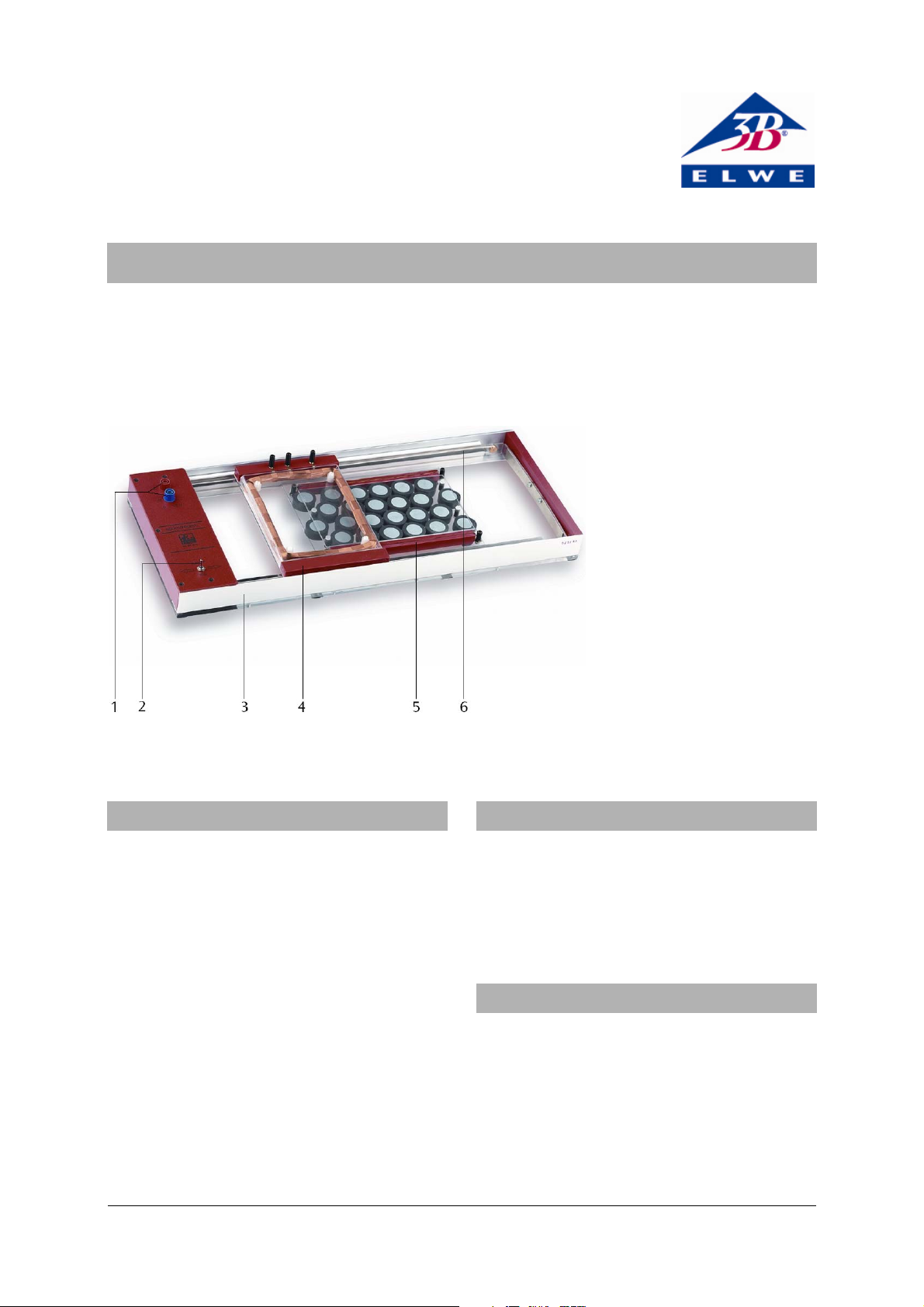
1 Operating voltage terminals
2 Pole changeover switch
3 Basic instrument
4 Frame with coil
5 Magnet plate
6 Conveyor belt
1. Description
The induction apparatus allows demonstration and
investigation of an induced voltage resulting from
the motion of a coil wound onto a frame passing
over a plate of magnets. By varying the coil frame's
speed and the number of turns in the coil itself, the
law of induction can be quantifiably verified by experiment. The rolling motion of a current carrying
conductor can also be demonstrated in the magnetic
field of the magnet plate of this apparatus.
The coil is moved at a constant speed over the magnet plate by a motor driving a belt. This produces a
constant induction voltage. The direction of the coil's
movement can be reversed using a switch and the
speed can be varied via the operating voltage. The
transparent design of the magnet plate and the
frame with coil allows the equipment to be used in
combination with an overhead projector.
2. Contents
1 Basic instrument
1 Frame with coil
1 Plate of magnets
1 Brass tube
1 Fleece
3. Technical data
Frame with coil: 185 x 125 mm²
Coil taps: 800, 1600. 2400 turns
Total dimensions: 585 x 200 x 55 mm³
Operating voltage: 2 – 12 V DC
Connection terminals: 4-mm safety sockets
Weight: 3 kg approx.
1
Page 2
4. Sample experiments
4.1 General instructions
The following equipment is also needed for the experiments:
1 DC power supply, 1,5 – 15 V U8521121-115
or
1 DC power supply, 1,5 – 15 V U8521121-230
1 Measurement amplifier U8531401-115
or
1 Measurement amplifier U8531401-230
1 Multimeter ESCOLA10 U8531160
1 HF patch cord, BNC/4 mm plug U11257
• Before beginning an experiment, the metal
tracks on the basic instrument, under the frame
with coil and on the plate of magnets, as well as
the brass tube must be rubbed with the fleece to
ensure good electrical contact.
• Set up the induction apparatus either on top of
an an overhead projector or on a bench.
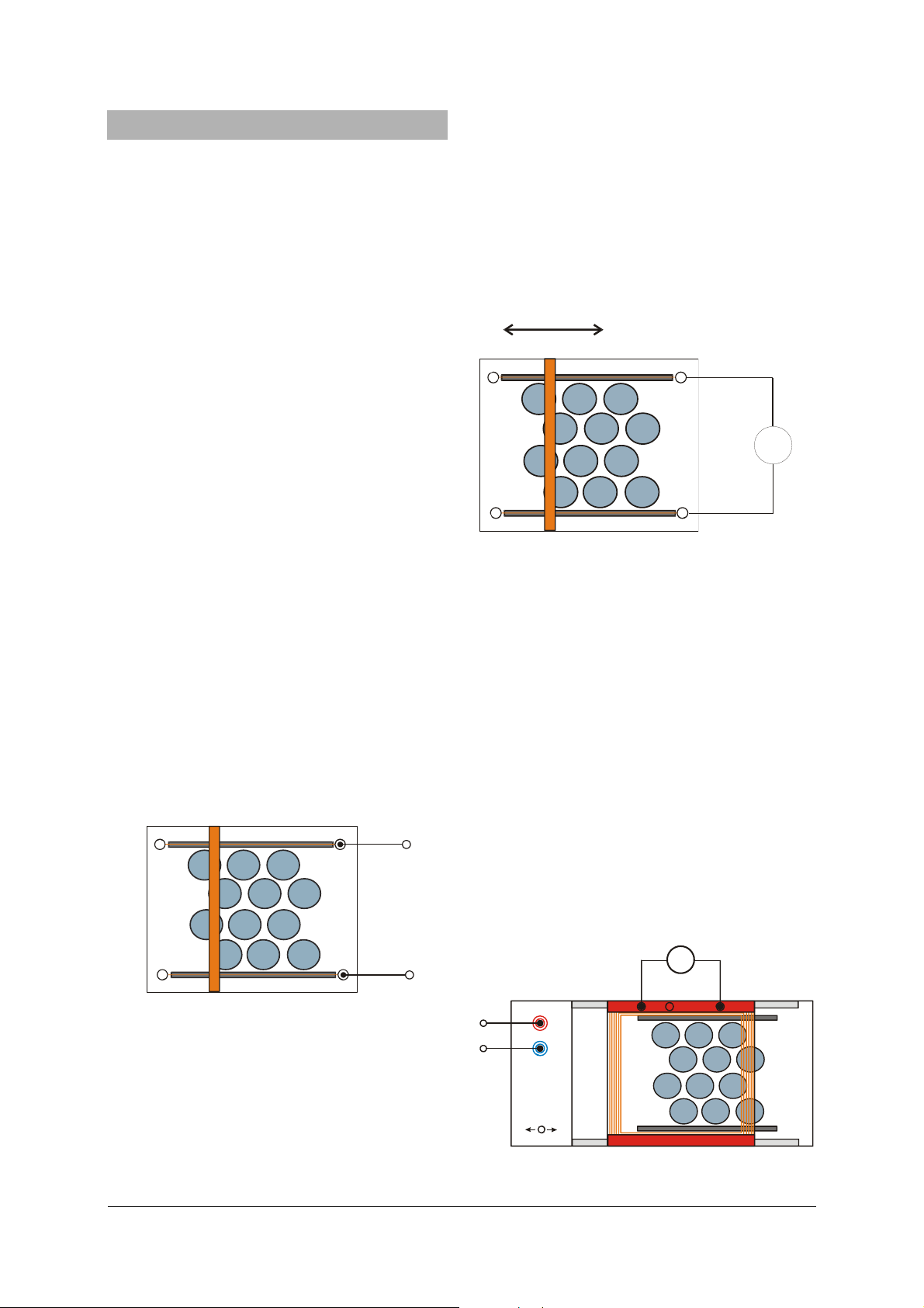
4.2 Movement of a current-carrying conductor in
a magnetic field
• Remove the magnet plate from the induction
apparatus.
• Place the brass tube across the magnet plate so
that the left and right-hand ends of the tube
touch the metal rails.
• Connect the magnet plate to the mains adaptor,
and feed 1 to 2 A into the sockets.
The brass tube starts to roll over the
magnet plate by
the Lorentz force acting on the current conducting
electrons in the tube. If the poles of the voltage
source are reversed the direction of the tube's motion is also reversed.
1 A-2 A
• Place the brass tube across the magnet plate so
that the left and right-hand ends of the pipe
touch the metal rails.
• While applying a slight downward pressure to
the brass tube, move it at a constant speed
through the magnetic field.
The voltmeter indicates a certain DC voltage. If the
tube's direction is reversed, an voltage of similar
magnitude arises with the opposite polarity. If the
speed is increased, the voltage rises too.
μ
V
Fig. 2 Electrical induction with a conductor
4.4 Electrical induction with a flat coil
• Place the frame with coil on the induction appa-
ratus.
• Connect the induction apparatus to the power
supply.
• Connect the multimeter to the coil. Set the zero
point at the middle of the scale and select the
100 mV measurement range.
• Slowly increase the operating voltage until the
conveyor belt slowly moves at a constant speed.
• Observe the induced voltage.
The voltmeter indicates a DC voltage. If the direction
of the conveyor belt is reversed, a voltage of similar
magnitude arises with the opposite polarity.
If the whole coil is located above the magnetic field,
there is no voltage induced. The coil surface is
smaller than the surface of the magnet plate, thus
the magnetic flux remains constant.
Fig. 1 Motion of a current-carrying conductor in a mag-
netic field
4.3 Electrical induction with a conductor
• Remove the magnet plate from the induction
apparatus
• Connect the signal amplifier to the sockets of the
metal tracks and set the measurement range to
100 μV.
mV
V
Fig. 3 Electrical induction using a flat coil
2
Page 3

4.5 Dependency of the induced voltage on the
number of turns and the speed of the induction loop
• Set up the experiment as specified in 4.4.
• Connect the multimeter initially to the tap
socket for 800 turns and measure the induced
voltage.
• Repeat the experiment at the same applied
voltage with 1600 and 2400 turns, and measure
the corresponding induced voltages.
• Compare the induced voltages.
The induced voltage is proportional to the number
of turns.
• Connect the multimeter to the tap socket for
2400 turns.
• Set the applied voltage to 4 V and measure the
induced voltage. Observe the speed of the flat
coil.
• Repeat the experiment at voltages of 6 V, 8 V
and 10 V.
• Compare the induced voltages.
The induced voltage is proportional to the speed of
the coil.
Fig. 4 Coil taps
800 1600
2400
Elwe Didactic GmbH • Steinfelsstr. 6 • 08248 Klingenthal • Germany • www.elwedidactic.com
3B Scientific GmbH • Rudorffweg 8 • 21031 Hamburg • Germany • www.3bscientific.com
Subject to technical amendments
© Copyright 2008 3B Scientific GmbH
Page 4

 Loading...