

Page 1
3B SCIENTIFIC® PHYSICS
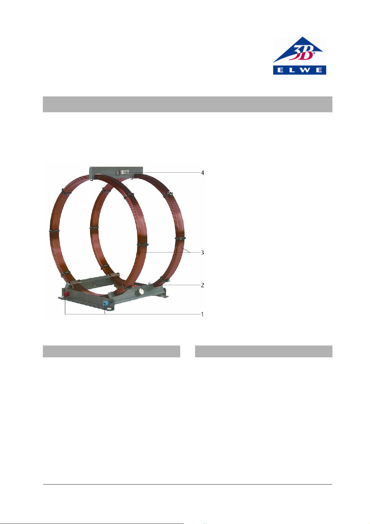
Pair of Helmholtz Coils U8481500
Instruction sheet
01/07 SP
1 Connection sockets
2 Knurled screw for mounting the
rotating frame with flat coil
3 Pair of coils
4 Spring clip for Hall sensor
1. Description
The Pair of Helmholtz coils is used for generating a
homogeneous magnetic field. In conjunction with
the rotating frame with flat coil (U8481510), the
Helmholtz coils are also used in experiments for
investigating induction and magnetic levitation. and
for the determination of the specific charge of the
electron e/m in conjunction with the electron-beam
tube (U8481420). The coils can be switched in parallel or in series. A spring clip on the top crossbar is
used to mount the Hall sensor during measurements
of the magnetic field.
2. Technical data
Number of turns per coil: 124
Outer coil diameter: 311 mm
Inner coil diameter: 287 mm
Mean coil radius: 1
Coil spacing: 150 mm
Enamelled copper wire thickness: 1.5 mm
DC resistance: 1.2 Ohm each
Maximum coil current: 5 A
Maximum coil voltage: 6 V
Maximum flux density at 5 A: 3.7 mT
Weight: 4.1 kg approx.
1
50 mm
Page 2
3. Theoretical bases
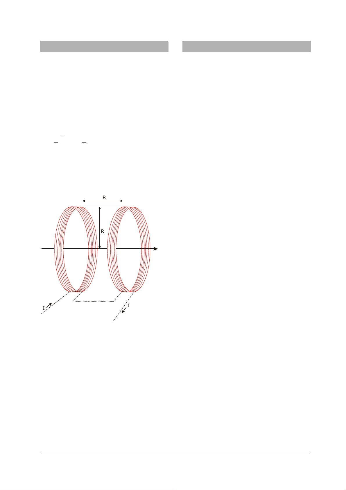
The special arrangement of the coils is attributed to
the physicist Hermann von Helmholtz. Two narrow
coils with a large radius R are set up parallel to one
another and on the same axis so that they are also
separated by a distance R. The magnetic field of each
individual coil is non-uniform. Upon superimposition
of the two fields, a region with a magnetic field that
is largely uniform is created between the two coils.
Given the Helmholtz arrangement of the pair of coils
and coil current I, the following holds true for the
magnetic flux density B of the magnetic field:
3
2
4
=
5
n
IB ⋅⋅µ⋅
0
R
where n = number of turns in each coil, R = mean
coil radius and µ
= magnetic field constant.
0
For the Helmholtz pair of coils, we get:
−4
I.B ⋅⋅=
104337 in Tesla (I in A).
Fig. 1 Coils in Helmholtz arrangement
4. Sample experiments
In order to perform the experiments,the following
equipment is also required:
1 AC/DC power supply 0-20 V, 5 A U8521131
2 Escola 10 multimeter U8531160
1 Rotating frame with flat coil U8481510
4.1 Voltage induction in a magnetic field
• Position the Helmholtz coils on the table top and
connect them in series to the DC power supply
via an ammeter.
• Screw the supports of the rotating frame with the
flat coil to the crossbar of the Helmholtz coils, so
that the flat coil can rotate in the middle of the
uniform field produced by the Helmholtz coils.
• Connect a voltmeter with a central zero point
directly across the coil.
• Set the power supply current for the coils to
about 1.5 A.
• Use the hand crank and observe the deflection of
the voltmeter.
• Change the speed of rotation so that a larger
deflection is obtained. The rotation speed needs
to be low.
In order to achieve a constant speed of rotation, use
of a slowly rotating motor (e.g. 12 V DC motor
U8552330) is recommended for driving the rotating
frame.
A precise voltage trace can also be observed and
measured using an oscilloscope.
4.2. Determination of the earth’s magnetic field
from the induction voltage
Using the same experiment set-up, it is also possible
to measure the earth’s magnetic field.
• Align the Helmholtz coils in such a way that the
magnetic field of the coils is parallel to the
Earth’s field.
• Rotate the flat coil and observe the voltage.
• Increase current to the Helmholtz coils until the
voltage induced at the outputs of the flat coil is
zero (so that the earth’s magnetic field and the
field of the Helmholtz coils cancel out).
• When the induced current is 0, then the mag-
netic field in the coils is of the same magnitude
as the Earth’s magnetic field.
2
Page 3

0-30
0-12 V
+
V
-
A
+
-
V
Fig. 2 Experiment set-up with flat coil and driving motor
Elwe Didactic GmbH • Steinfelsstr. 6 • 08248 Klingenthal • Germany • www.elwedidactic.com
3B Scientific GmbH • Rudorffweg 8 • 21031 Hamburg • Germany • www.3bscientific.com
Subject to technical amendments
Page 4

 Loading...