

Page 1

3B SCIENTIFIC
Instruction sheet
12/08 ELWE/ALF
®
PHYSICS
Heat pump U8440600
1 On/off switch for Compressor
2 Condenser
3 Stirrer
4 Overpressure cut-out switch
5 Reset overpressure cut-out switch
6 Manometer for the high-pressure side
7 Manometer for the low-pressure side
8 Energy monitor
9 Expansion valve
10 Evaporator
11 Stirrer
12 Viewing window
13 Compressor
1. Safety instructions
If the heat pump is tipped to one side, it must remain in an upright position for at least seven hours
before being operated again.
• Always keep the heat pump in an upright posi-
tion during storage, transport and operation.
• Carry the heat pump only at the carrying handles.
• Do not lift the heat pump by its copper pipes or
they may get bent.
Caution: the voltage in the compressor circuit is
dangerous to touch!
• Do not thermally insulate the compressor or it
may overheat.
• After shut-down by the overpressure cut-out
switch wait for 10 minutes to press the green reset button.
2. Description
Demonstration model of an electrically powered
compressor heat pump for demonstrating how a
heat pump or a refrigerator operates. Can be operated as a water-air or water-water heat pump.
The demonstration model of an electrically powered
compressor heat pump consists of a compressor with
a drive motor, an evaporator, a condenser and an
expansion valve. These components are connected in
a closed system by means of pipes and built onto a
base.
The energy monitor allows to record and display the
electrical performance data of the compressor.
1
Page 2
Button Function
Zeit (Time) displays the time / operating time of
the compresor (ED)
(changes when you press the button)
Strom (Current)
Spannung
displays the current consumption of
the compresor
displays the mains voltage
(Voltage)
Leistung
(Power)
Energie
displays the momentary power consumption
displays the energy, (unit: Wh)
3.1 The processes in a heat pump circuit
In the most important and widely used type of heat
pump, the compressor heat pump, a substance in
the form of a liquid with a low boiling point circulates in a closed loop. It passes through four different processes. It is evaporated, compressed, condensed and then allowed to expand (see Fig. 1).
(Energy)
Zeit (Time)
> 6s
Reset function for time, ED and
energy
The evaporator and condenser are constructed as
coils of copper piping and each is immersed in a
beaker filled with 2000 ml of water that serves as a
reservoir of heat in order to determine the quantity
of energy absorbed or emitted. Two additional thermometers are required in order to measure the
temperature of the water in the beakers.
Two large manometers display the pressure of the
refrigerant in both heat exchangers. An overpressure
cut-out switch disconnects the heat pump from the
mains if the excess pressure reaches 15 bars.
So that the properties of the refrigerant in liquid and
gaseous states and the processes of conversion can
be viewed, the heat pump is equipped with viewing
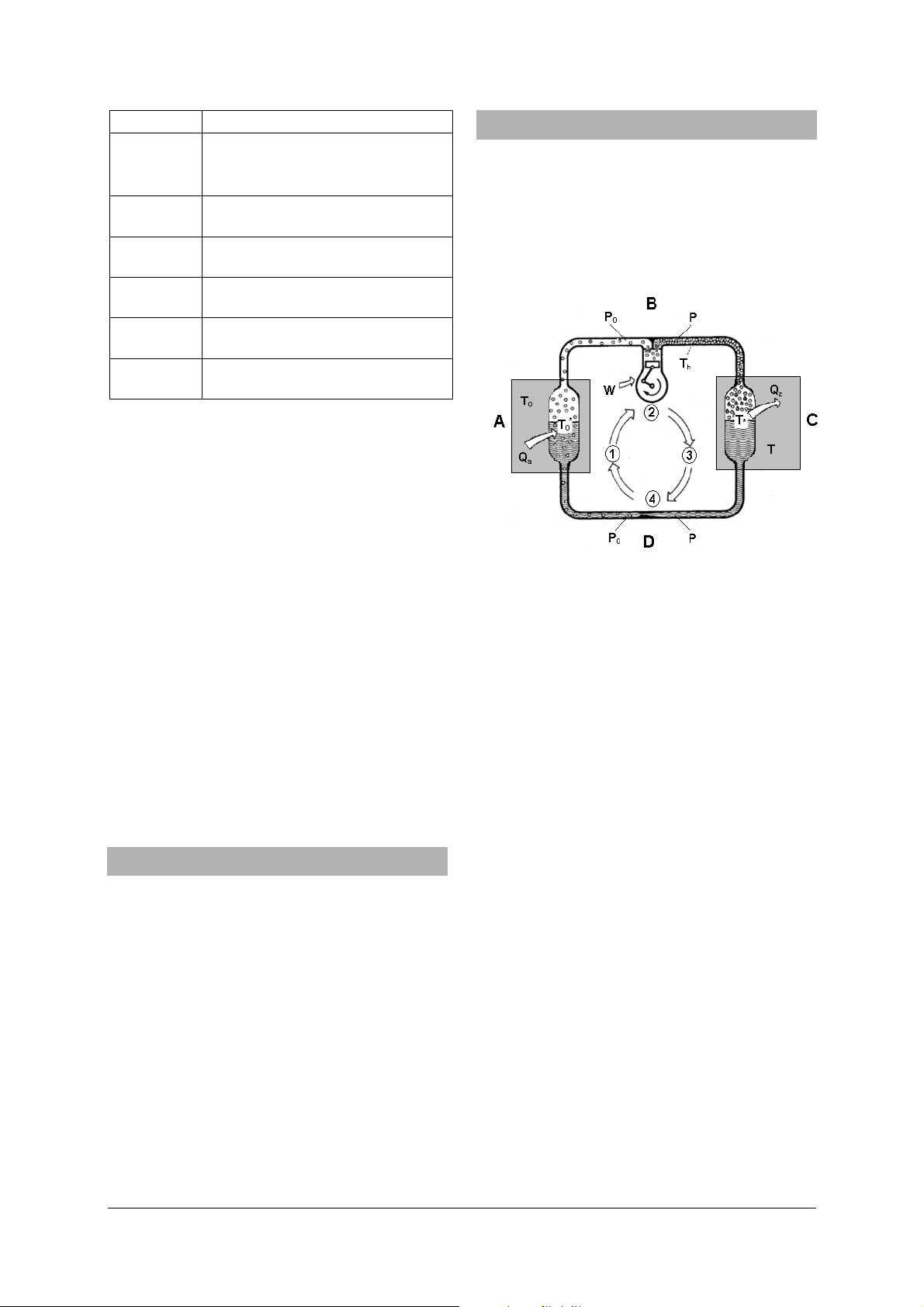
Fig. 1 Circulation in a heat pump
A Evaporator
B Compressor
C Condenser
D Expansion valve
P
windows. These allow the interior of the pump to be
seen and the state of the refrigerant to be observed
immediately after the evaporator or condenser.
p High pressure in the condenser segment from
The heat pump is available for two different mains
volatages. U8440600-230 is designed for 230 V (±10
%), 50 Hz mains supplies, while the U8440600-115
T
model is for 115 V (±10 %), 60 Hz supplies.
T Temperature of the medium (usually centrally
3. Technical data
Compressor power: 120 W, power consump
tion dependent on operat ing state
Evaporator temperature: -10° C
Refrigerant (CFC-free): R 134A (Tetrafluorethan, C
2H2F4
Boiling point: -26° C
Manometer: 160 mm dia., evaporator
(suction intake) up to 9
bars; condenser (pressure
pipe) up to 24 bars
Overpressure cut-off: disconnects compressor
from the mains at 15 bars
T
rator at pressure p
T
after compression
)
T* Boiling point of the refrigerant in the con-
denser at pressure p
Q
Q
W Work performed by the compressor
3.1.1 Evaporation
Power supply: 115 V, 60 Hz or 230 V, 50 Hz
Dimensions: 750 x 350 x 540 mm
3
Weight: 21 kg approx.
4. Operating principle
Low pressure in the evaporator segment from
0
the outlet of the expansion valve to the input
of the compressor
the outlet of the compressor to the input of
the expansion valve
Temperature of the medium (soil, water, air)
0
surrounding the evaporator from which a
quantity of heat Q
is absorbed
a
heated water), surrounding the condenser
which absorbs a quantity of heat Q
* Boiling point of the refrigerant in the evapo-
0
Temperature of the refrigerant vapour
h
Heat absorbed by the evaporator
a
Heat emitted by the condenser
Z
0
z
In the evaporator the liquid refrigerant experiences a low pressure p
. The temperature T0 in
0
the medium surrounding the evaporator is higher
than the boiling point of the refrigerant T
responding to the pressure p
. This tempera-
0
* cor-
0
2
Page 3

ture gradient leads to heat being transferred
from the surroundings into the refrigerant, which
therefore boils and turns into vapour. The quantity of heat Q
required for this evaporation is
a
taken from the surroundings, which cool down as
a result.
3.1.2 Compression
The refrigerant vapour is constantly drawn into
the compressor where it is compressed. This
causes the vapour pressure to rise from p
to p.
0
The boiling point at pressure p is T*. The work W
performed by the compressor raises the temperature of the vapour to T
> T*. Th is the temperature
h
of the refrigerant vapour after it has been thus
raised, i.e. the temperature is above the boiling
point T* corresponding to the pressure p after the
compressor.
3.1.3 Condensing
The compressed vapour is forced into the condenser. The temperature of the surroundings
around the condenser is T and is lower than T*. This
means that heat is transferred from the refrigerant
into the environment. This corresponds to the
smaller fraction of Q
pour decreases from T
. The temperature of the va-
z
but the vapour does not con-
h
dense until the condensation temperature T* is
reached. At that point the vapour begins to condense (become liquid) and the heat of condensation, the greater component of Q
, is transferred to
z
the surroundings, the temperature of which therefore rises.
3.1.4 Expansion
The piping connecting the condenser and the
evaporator completes the circuit. The expansion
valve in this pipe allows the pressure difference to
even out. The liquid refrigerant at temperature T* is
allowed to expand so that its pressure decreases
from p in the condenser to p
in the evaporator. This
0
also causes the refrigerant to cool. The lower pressure p
results in a lower boiling point T0*. There-
0
fore the expansion also causes the boiling point to
drop so that the temperature T* at which the refrigerant leaves the evaporator is now above the
boiling point of the expanded fluid. Part of it therefore starts to evaporate. The heat of evaporation required for this is provided by the cooling of the refrigerant itself until pressure and temperature reach
p
and T0* and the refrigerant returns to its initial
0
state thus completing the cycle.
The heat energy required to evaporate the refrigerant
per unit time in the evaporator can be supplied either
by the extensive cooling of a small volume of air or by
lesser cooling of a large volume of air. The energy
associated with a material is dependent on its temperature and its quantity. In practice the cooling of
the medium around the evaporator, such as the cooling of air outdoors, only corresponds to a few degrees.
3.2 The processes in the circuit as a T, Q/T diagram
The heat pump cycle is often represented in a state
diagram with the «Temperature» T as its ordinate and
the quotient «Heat divided by absolute temperature»
Q/T, which is called entropy, as the abscissa (Fig. 2).
The value x in this diagram represents the ratio of
refrigerant vapour to liquid. When x = 0 and anywhere
to the left of this line (left-hand limit), all the refrigerant
is liquid. To the right of the line an increasing quantity
of the refrigerant is gaseous until a line with x = 1
(right-hand limit) is reached, after which the refriger-
ant is entirely vapour. The sequence of processes in
the cycle already described will now be explained
again in terms of this diagram:
Fig. 2 The process in a heat pump cycle as a T, Q/T diagram
A Evaporator, B Compressor, C Condenser, D Expansion
valve
Gaseous refrigerant at a pressure p
T
* (state 1) is sucked into the compressor and com-
0
and temperature
0
pressed. The amount of work done in this case is W.
This is converted into heat and transferred to the
refrigerant. The pressure p
increases to p. The higher
0
pressure p corresponds to a higher boiling point T*.
Temperature rises from T
* to Th (state 2).
0
The compressed refrigerant flows into the condenser.
The temperature of the condenser's surroundings T is
lower than T*. By emitting heat, the vapour cools
from T
down to the condensation temperature, the
h
boiling point T* corresponding to the pressure p (state
2'). It then condenses by emitting its heat of conden-
sation (Q
).
z
Now that the refrigerant is liquid at temperature T*
and pressure p (state 3) it is allowed to flow to the
evaporator via an expansion valve. During the course
of this, the pressure drops back to p
pressure causes the temperature to fall to T
, and the drop in
0
* (state 4).
0
3
Page 4

The low pressure in the evaporator allows the liquid
Δ
⋅
⋅=Δ
refrigerant to boil at a low temperature T
Q
required for this is absorbed from the surroundings
a
as long as they are at a temperature T
*. The heat
0
where T0 > T0*.
0
The refrigerant vapour then returns to a pressure and
temperature of p
and T0* (state 1) and is once again
0
sucked into the compressor.
In the T, Q/T diagram the quantities of energy are
indicated by areas
=Δ
. The area beneath
T/QTQ
the line between 4 and 1 where the refrigerant boils
(p
= const., T0* = const.), for example, represents the
0
heat of evaporation Q
transferred to the refrigerant.
a
If such a machine were to operate without losses, the
quantity of heat Q
emitted from the condenser would
z
be equal to the sum of the work W done by the
compressor and the heat Q
absorbed in the evapora-
z
tor.
4. Example experiment
Determining the efficiency ε
Two thermometers are required to measure the rise
or fall in temperature in the water vessels.
• Take the beakers from the heat pump and fill
them with water.
• Put back the reservoirs as follows:
• Place the beakers carefully on the base plate and
move them with the low edge first under the
evaporator and the condenser.
• Turn the beakers in such a way that the high
edge points to the back wall.
• Lift up the beakers and mount them into the
retaining plates.
• Connect the heat pump to the mains supply.
• Allow the compressor to run for about 10 min-
utes before starting the experiment until it
reaches its operating temperature. Then replace
the water and start the experiment.
• Push the button „Zeit“ (time) at the energy
monitor for 6 seconds and at the same time
switch on the compressor. (toggle switch to the
right)
The energy monitor starts the time measurement
and records the power consumption of the compressor.
• The water should be stirred thoroughly through-
out the experiment.
The efficiency ε is given by the ratio of the change in
energy ΔQ provided to the heat reservoir per unit
time Δt, to the power P supplied to the compressor
to perform its work:
Δ
=ε
.
tPQΔ⋅
ΔQ is given by
TmcQ Δ⋅
where c = specific
heat capacity and m = mass of water.
The efficiency ε decreases as the temperature differ-
ence between the evaporator and the condenser
increases.
To optimise efficiency the water beakers and the
pipes (but not the compressor) can be insulated with
foam strips, for example, in order to prevent radia-
tion losses.
Elwe Didactic GmbH • Steinfelsstr. 6 • 08248 Klingenthal • Germany • www.elwedidactic.com
3B Scientific GmbH • Rudorffweg 8 • 21031 Hamburg • Germany • www.3bscientific.com
Technical amendments are possible
© Copyright 2008 3B Scientific GmbH
 Loading...