

Page 1
3B SCIENTIFIC3B SCIENTIFIC
3B SCIENTIFIC®
3B SCIENTIFIC3B SCIENTIFIC
U10365 Wärmeäquivalentgerät
U10366 Kupferzylinder
Bedienungsanleitung
9/04 MH
PHYSICSPHYSICS
PHYSICS
PHYSICSPHYSICS
®
1
2
56897blbm
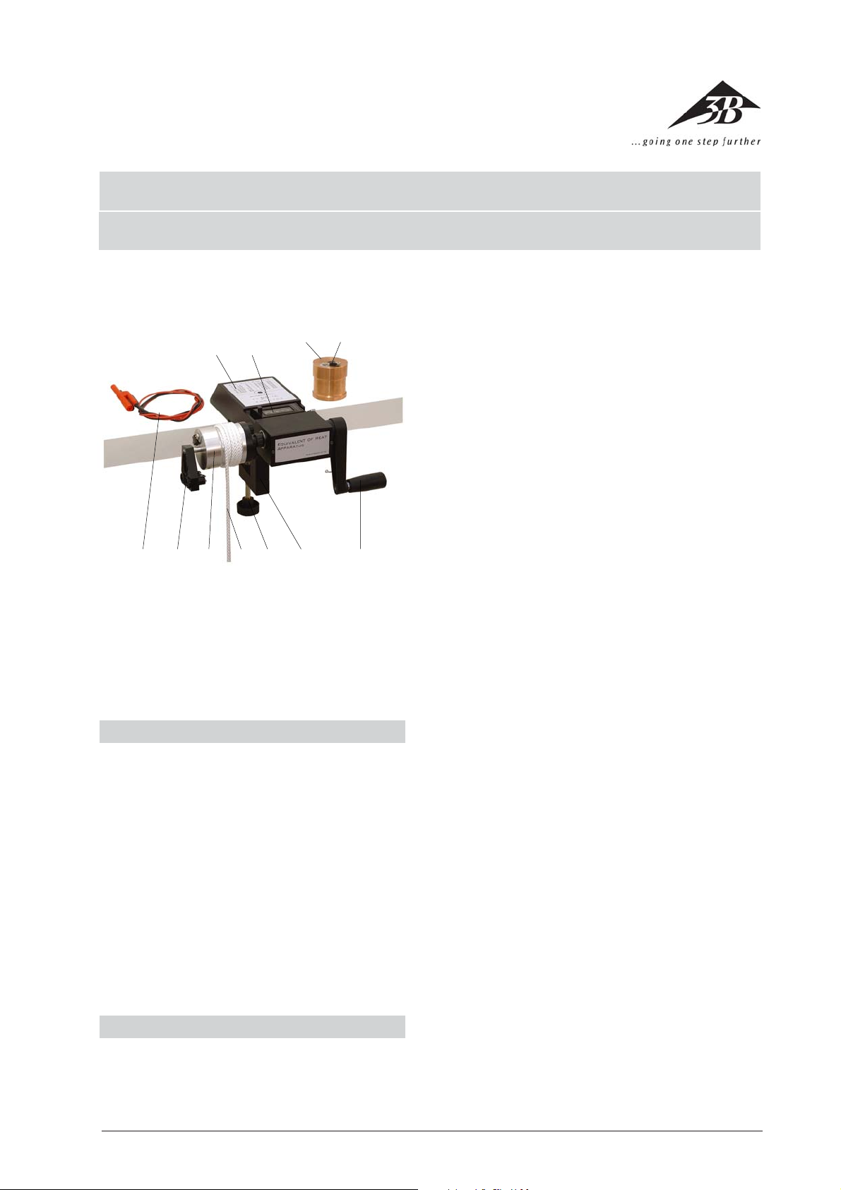
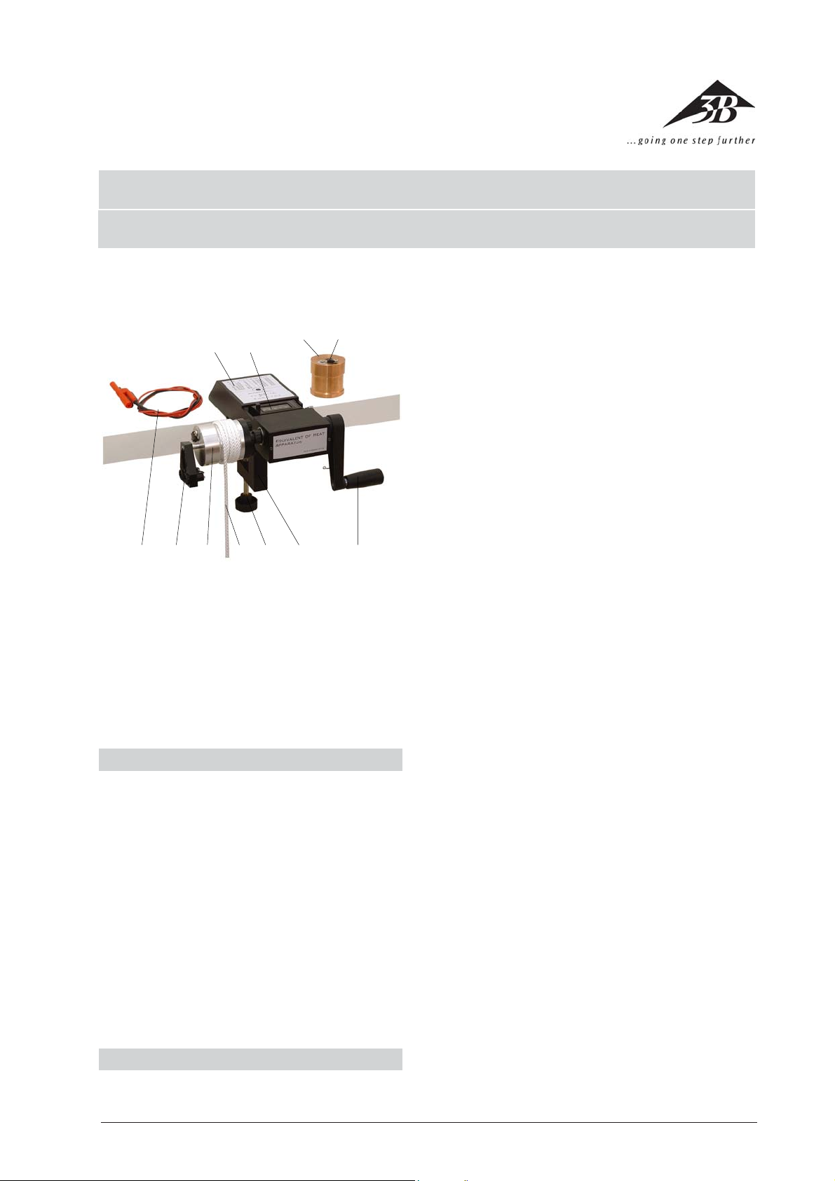
Fig.1: Komponenten
Mit dem Wärmeäquivalentgerät kann mechanische
Arbeit (Nm) und elektrische Energie (Ws) in Wärme (J)
umgewandelt werden. Die Auswertung zeigt die Äquivalenz aller drei Energieformen.
1. Sicherheitshinweise
• Verletzungsgefahr! Das an der Reibschnur 8 be-
festigte Gewicht (ca. 5 kg) kann beim Herabfallen
Personen verletzen. Es sollte zur Befestigung auf
dem Boden stehen und während der Versuche max.
ca. 10 cm angehoben werden.
• Verbrennungsgefahr! Während der Versuche wird
der Reibzylinder (3/ 9) erwärmt. Es ist darauf zu
achten, dass die Temperatur nicht über ca. 40 °C
ansteigt. Der maximal zulässige Strom im Heizelement beträgt 3 A und darf nicht überschritten
werden.
• Stromschlaggefahr! Die maximale Ausgangs-Span-
nung des verwendeten Netzgerätes bei der elektrischen Beheizung darf 40 V nicht überschreiten.
2. Beschreibung, technische Daten
Mit dem Wärmeäquivalentgerät kann die Äquivalenz
von mechanischer Reibungsarbeit (Nm), elektrischer
Energie (Ws) und Wärme (J) gezeigt werden. Die in Nm
34
1 Träger mit Tabelle zur Umrechnung:
Widerstand → Temperatur
2 Zählwerk
3 Kupferzylinder (U10366)
4 Elektrisches Heizelement
5 Handkurbel
6 Tischklemme
7 Rändelschraube
8 Reibschnur mit Gegengewicht (nicht sichtbar)
9 Aluminiumzylinder
bl Temperaturfühler
bm Adapterkabel
bn Eimer, 5 (nicht sichtbar)
bzw. Ws ermittelten Werte stimmen auf etwa 2% überein. Wird diese Äquivalenz vorausgesetzt, kann die spezifische Wärmekapazität von Aluminium bzw. Kupfer
bestimmt werden.
Durch die stabile Konstruktion mit einem eingebauten Umdrehungszählwerk und einer doppelt kugelgelagerten Welle sind die Versuche so einfach wie
möglich durchführbar. Zur Temperaturmessung kommt
ein Widerstand mit negativem Temperaturkoeffizienten (NTC) zum Einsatz, der sicher in einer Aluminiumhülse untergebracht ist. Die Aluminiumhülse schnappt
in die Reibzylinder ein, wodurch sie nicht unbeabsichtigt herausrutschen kann.
Technische Daten der Reibzylinder (ca. Angaben):
Durchmesser D: 48 mm
Höhe: 50 mm
Aluminiumzylinder: Masse mA = 250 g,
spezifische Wärmekapazität
cA = 0,86 kJ/kg K,
Kupferzylinder: mK = 750 g, cK = 0,41 kJ/kg K
Elektrischer Anschluss: Buchsen mit 2 mm Durchmesser,
Pluspol „+“ isoliert,
Minuspol „–“ an Masse,
Verpolung führt nicht
zur Zerstörung.
1
Page 2

3. Bedienung und Wartung
• Das Wärmeäquivalentgerät wird mit der Tisch-
klemme an einer stabilen Arbeitsplatte befestigt.
Dann wird die Reibschnur – wie in Fig. 1 gezeigt –
4,5 bis 5,5 mal um den Reibzylinder gelegt, wobei
das Gegengewicht hinten und das lose Ende der
Schnur vorne herunterhängen sollte.
• Als Gewicht kann der beiliegende Eimer, der mit
Wasser oder Sand etc. gefüllt wird (Gesamtmasse
ca. 5 kg), verwendet werden. Das lose Ende der Reibschnur wird mit dem auf dem Boden stehenden
Gewicht verbunden, wobei darauf zu achten ist,
dass das Gegengewicht bei straffer Schnur nur etwa
5 cm Abstand vom Boden hat. Dadurch wird ein
Anheben des Gewichtes während des Versuchs um
mehr als ca. 10 cm verhindert.
• Wenn sich jetzt beim Kurbeln zeigt, dass die Schnur
nach rechts läuft und ggf. nicht in der Vertiefung
bleibt, dann wird die Schnur so um den Reibzylinder gelegt, dass sich das Schnurende mit dem
Gewicht rechts und das Schnurende mit dem Gegengewicht links befindet.
• Der Temperaturfühler wird mit einem Tropfen Öl
benetzt (wichtig!) und gemäß Fig. 1 in den gewähl-
ten Reibzylinder gesteckt, bis er merklich einrastet
und sich leicht drehen lässt (wird er zu weit oder
nicht weit genug hineingeschoben dreht er sich
nicht einwandfrei). Die beiden Anschlüsse des
Temperaturfühlers werden mit einem Widerstandsmessgerät (Multimeter) verbunden, das im Bereich
von 2 kΩ bis 9 kΩ mindestens über eine 3-stellige
Anzeige verfügen sollte. Die Umrechnung des gemessenen Widerstands in die Temperatur kann
entweder unter Verwendung der Tabelle auf der
letzten Seite dieser Anleitung oder mit Hilfe folgender Gleichung erfolgen:
217
T
=−
151
0,13
R
(1)
hier ist R in kΩ einzusetzen, um T in °C zu erhalten. Diese Gleichung stimmt mit den Tabellenangaben des Herstellers von dem NTC-Widerstand im
Bereich von 10 - 40 °C auf ± 0,05 °C überein.
• Vor einem Versuch sollte der Reibzylinder um ca.
5 - 10 °C unter Umgebungstemperatur abgekühlt
werden. Dazu kann er entweder in einen Kühlschrank oder in kaltes Wasser gestellt werden, wobei die Temperaturfühler-Bohrung nach oben zeigen muss und die Eintauchtiefe nur etwa 2/3 der
Zylinderhöhe betragen darf (Tipp: wird der Reibzylinder in einer Plastiktüte ins Wasser gestellt, muss
er nach der Abkühlung nicht abgetrocknet werden).
• Die Temperaturerhöhung während eines Versuchs
sollte solange erfolgen, bis die Reibzylinder-Temperatur ca. 5 - 10 °C über der Umgebungstemperatur liegt. Je genauer die Temperaturdifferenzen (jeweils gegen Umgebungstemperatur)
bei der Abkühlung und Erwärmung übereinstimmen, desto geringer ist der Netto-Wärmeaustausch
mit der Umgebung.
• Zur elektrischen Beheizung der Reibzylinder liegen
Adapterkabel bei, die auf der einen Seite Stecker
mit 2 mm Durchmesser und auf der anderen Seite
die üblichen Laborstecker mit 4 mm Durchmesser
haben. Zur Stromversorgung sollte ein Netzteil mit
regelbarer Spannungs- und Strombegrenzung zum
Einsatz kommen, wobei die maximale Spannung
des Netzteils 40 V nicht überschreiten darf. Der Pluspol des Netzgerätes wird mit der isolierten Buchse
(an dem runden grauen Kunststoffplättchen unter
der Buchse zu erkennen) und der Minuspol mit der
anderen Buchse verbunden.
• Die Heizelemente an den Reibzylindern verhalten
sich nicht wie Ohmsche Widerstände! Ab ca. 10 V
steigt der Strom schnell an, bis er bei ca. 12 V die
maximal zulässige Stromstärke von 3 A erreicht. Zur
Einstellung eines Betriebspunktes empfiehlt es sich,
zunächst die Strombegrenzung auf 2 – 3 A einzustellen und dann die Spannung langsam bis auf ca.
11 V anzuheben, wobei der Strom auf ca. 1 A steigen sollte. Jetzt wird die Strombegrenzung nachgeregelt, bis ca. 0,8 A fließen. Diese Einstellungen
werden jetzt nicht mehr verändert; bis zum Versuch wird der Strom einfach durch Abziehen der
Kabel unterbrochen. Durch die aktive Strombegrenzung und die nicht Ohmsche Charakteristik
bleiben Spannung und Strom trotz Temperaturänderung während eines Versuchs nahezu konstant.
• Wartung: Das Wärmeäquivalentgerät ist prinzipi-
ell wartungsfrei. Zur Reinigung kann es feucht (Wasser mit Spülmittel) abgewischt werden. Lösungsmittel sollten nicht verwendet werden. Auch das Eintauchen in Wasser ist zu vermeiden.
• Die Reibzylinder sollen metallisch blank sein. Falls
sich ein Belag gebildet haben sollte, kann dieser
mit einem Metall-Putzmittel beseitigt werden.
• Die Reibschnur kann ggf. gewaschen werden. Als
kostengünstige Ersatzschnur kann geflochtenes
Polyamidseil (z. B. Baumarkt) verwendet werden.
4. Versuchsdurchführung und Auswertung
4.1 Umwandlung mechanischer Arbeit in Wärme
4.1.1 Versuchsdurchführung
• Zuerst werden die verschiedenen Massen be-
stimmt:
Hauptgewicht (z. B. Eimer mit Wasser) mH = 5,22 kg
Gegengewicht (an Reibschnur) mG = 0,019 kg
Aluminiumzylinder mA = 0,249 kg
• Weitere Größen, die vorab gemessen werden soll-
ten:
Umgebungstemperatur TU = 23,2 °C
Durchmesser des Zylinders an der Reibfläche
DR = 45,75 mm
• Nach der Abkühlung des Reibzylinders wird die-
ser an den Träger geschraubt, der Temperaturfühler eingesteckt und die Reibschnur um den
Zylinder gelegt (vergl. Abschnitt 3). Nach ein paar
Minuten, die zur homogenen Temperaturverteilung verstreichen sollten, beträgt der Wider-
2
Page 3

stand des Temperaturfühlers R
= 8,00 kΩ (ent-
1
sprechend T1 = 14,60 °C nach Gl. 1).
• Nach Kontrolle der Nullstellung des Zählers wird
der Versuch gestartet, indem die Kurbel gedreht
und dadurch das Hauptgewicht vom Boden abgehoben wird. Jetzt senkt sich das Gegengewicht
auf den Boden, wodurch die Reibschnur leicht
entspannt wird und etwas weniger auf dem Zylinder reibt. Das Hauptgewicht hält jetzt seine
Höhe und sollte diese während des ganzen Versuchs beibehalten.
• Nach n = 460 Umdrehungen wird der Versuch
beendet und der Widerstandswert abgelesen:
R
= 3,99 kΩ (T
2
= 30,26 °C). Da die Temperatur
2
direkt nach Versuchsende noch kurz ansteigt
(Homogenisierung der Temperaturverteilung),
wird als Messwert der Minimalwert des Widerstandes notiert, der einige Sekunden nach Versuchsende erreicht ist. Danach steigt der Widerstand
wieder an, da durch Wärmetausch mit der Umgebung die Temperatur des Zylinders fällt.
4.1.2 Versuchsauswertung
• Arbeit W ist definiert als das Produkt von Kraft F
und Weg s
W = Fs (2)
• Bei der Reibung wirkt die Kraft
F = mA g (3)
(g ist die Erdbeschleunigung) entlang des Weges
s = F n π D
r
(4)
• Einsetzen der Gln. 3 und 4 in 2 liefert:
W = m
gn π D
A
= 5,22 x 9,81
R
x 460 x 3,1416 x 0,04575Nm = 3386Nm (5)
• Die im Reibzylinder gespeicherte Wärme ∆Q er-
gibt sich aus der der Temperaturdifferenz (T2– T1)
und der in Abschnitt 2 angegebenen spezifischen
Wärmekapazität zu:
∆Q = c
(T2– T1) = 0,86 x 0,249
A mA
x (30,26 – 14,60) kJ = 3353 J (6)
• In diesem Beispiel beträgt die Abweichung zwi-
schen mechanischer Arbeit und Wärme nur etwa
1%. Durch unvermeidbare Toleranzen in der Material-zusammensetzung (reines Aluminium ist sehr
weich und lässt sich mechanisch kaum bearbeiten,
weshalb immer Legierungen zum Einsatz kommen)
kann die spezifische Wärmekapazität jedoch merklich schwanken. Sie sollte individuell für jeden Reibzylinder bestimmt werden. Dies ist am einfachsten durch elektrische Beheizung und unter Voraussetzung der Äquivalenz von Wärme und elektrischer
Energie durchführbar.
4.2 Umwandlung elektrischer Energie in Wärme
4.2.1 Versuchsdurchführung
• Nach der Abkühlung des Reibzylinders wird dieser
an den Träger geschraubt (gleiche Versuchsbedingungen wie beim Reibungsversuch) und der
Temperaturfühler eingesteckt. Nach ein paar Minuten, die zur homogenen Temperaturverteilung verstreichen sollten, beträgt der Widerstand des
Temperaturfühlers R
= 8,00 kΩ (entsprechend
1
T1 = 14,60 °C nach Gl. 1).
• Jetzt wird das vorab eingestellte Netzgerät (siehe
Abschnitt 3) an das Heizelement angeschlossen
und eine Stoppuhr gestartet. Spannung und Strom
(Anzeige am Netzgerät) werden notiert:
U = 11,0 V , Ι = 0,510 A
• Nach t = 600 s wird der Versuch beendet und der
Widerstandswert abgelesen:
R
= 3,98 kΩ (T
2
= 30,32 °C).
2
4.2.2Versuchsauswertung
• Die elektrische Energie E ist das Produkt aus Leis-
tung P und Zeit t. Die Leistung wiederum ist das
Produkt aus Spannung und Strom. Demnach gilt:
EUT= = 11,0 x 0,512 x 600 = 3379WsI
(7)
• In diesem Versuch beträgt die zugeführte Wärme
∆Q = c
(T2– T1) = 0,86 x 0,249
A mA
x (30,32 – 14,60) kJ = 3366 J (8)
• Auch hier ist die Übereinstimmung zwischen E und
∆Q sehr gut.
Zusammenhang zwischen Widerstand und Temperatur beim Temperaturfühler
RR
/ k / k
ΩΩ
TT
/ /
R
/ k
Ω
RR
/ k / k
ΩΩ
CC
T
/ °
C
TT
/ /
CC
RR
/ k / k
ΩΩ
TT
/ /
R
/ k
Ω
RR
/ k / k
ΩΩ
CC
T
/ °
C
TT
/ /
CC
RR
/ k / k
ΩΩ
TT
/ /
R
/ k
Ω
RR
/ k / k
ΩΩ
CC
T
/ °
C
TT
/ /
CC
RR
/ k / k
ΩΩ
TT
/ /
R
/ k
Ω
RR
/ k / k
ΩΩ
CC
T
/ °
C
TT
/ /
CC
RR
/ k / k
ΩΩ
R
/ k
Ω
RR
/ k / k
ΩΩ
TT
/ /
T
/ °
TT
/ /
7,86 14,97 6,78 18,19 5,70 22,05 4,62 26,84 3,54 33,10
7,84 15,03 6,76 18,26 5,68 22,13 4,60 26,94 3,52 33,24
7,82 15,08 6,74 18,32 5,66 22,21 4,58 27,04 3,50 33,38
7,80 15,14 6,72 18,39 5,64 22,29 4,56 27,14 3,48 33,51
7,78 15,19 6,70 18,45 5,62 22,37 4,54 27,24 3,46 33,65
7,76 15,25 6,68 18,52 5,60 22,45 4,52 27,35 3,44 33,79
7,74 15,31 6,66 18,58 5,58 22,53 4,50 27,45 3,42 33,93
7,72 15,36 6,64 18,65 5,56 22,61 4,48 27,55 3,40 34,07
7,70 15,42 6,62 18,72 5,54 22,69 4,46 27,66 3,38 34,22
7,68 15,47 6,60 18,78 5,52 22,77 4,44 27,76 3,36 34,36
3
CC
C
CC
Page 4

RR
/ k / k
ΩΩ
TT
/ /
R
/ k
Ω
RR
/ k / k
ΩΩ
7,66 15,53 6,58 18,85 5,50 22,85 4,42 27,87 3,34 34,50
7,64 15,59 6,56 18,92 5,48 22,94 4,40 27,97 3,32 34,65
7,62 15,64 6,54 18,99 5,46 23,02 4,38 28,08 3,30 34,79
7,60 15,70 6,52 19,05 5,44 23,10 4,36 28,18 3,28 34,94
7,58 15,76 6,50 19,12 5,42 23,19 4,34 28,29 3,26 35,09
7,56 15,81 6,48 19,19 5,40 23,27 4,32 28,40 3,24 35,24
7,54 15,87 6,46 19,26 5,38 23,35 4,30 28,51 3,22 35,39
7,52 15,93 6,44 19,33 5,36 23,44 4,28 28,62 3,20 35,54
7,50 15,99 6,42 19,40 5,34 23,52 4,26 28,72 3,18 35,69
7,48 16,05 6,40 19,46 5,32 23,61 4,24 28,83 3,16 35,84
7,46 16,10 6,38 19,53 5,30 23,69 4,22 28,95 3,14 36,00
7,44 16,16 6,36 19,60 5,28 23,78 4,20 29,06 3,12 36,15
7,42 16,22 6,34 19,67 5,26 23,87 4,18 29,17 3,10 36,31
7,40 16,28 6,32 19,74 5,24 23,95 4,16 29,28 3,08 36,47
7,38 16,34 6,30 19,81 5,22 24,04 4,14 29,39 3,06 36,63
7,36 16,40 6,28 19,88 5,20 24,13 4,12 29,51 3,04 36,79
7,34 16,46 6,26 19,95 5,18 24,21 4,10 29,62 3,02 36,95
7,32 16,52 6,24 20,03 5,16 24,30 4,08 29,74 3,00 37,11
7,30 16,57 6,22 20,10 5,14 24,39 4,06 29,85 2,98 37,28
7,28 16,63 6,20 20,17 5,12 24,48 4,04 29,97 2,96 37,44
7,26 16,69 6,18 20,24 5,10 24,57 4,02 30,09 2,94 37,61
7,24 16,75 6,16 20,31 5,08 24,66 4,00 30,20 2,92 37,78
7,22 16,81 6,14 20,39 5,06 24,75 3,98 30,32 2,90 37,94
7,20 16,88 6,12 20,46 5,04 24,84 3,96 30,44 2,88 38,11
7,18 16,94 6,10 20,53 5,02 24,93 3,94 30,56 2,86 38,29
7,16 17,00 6,08 20,60 5,00 25,02 3,92 30,68 2,84 38,46
7,14 17,06 6,06 20,68 4,98 25,11 3,90 30,80 2,82 38,63
7,12 17,12 6,04 20,75 4,96 25,21 3,88 30,92 2,80 38,81
7,10 17,18 6,02 20,83 4,94 25,30 3,86 31,04 2,78 38,99
7,08 17,24 6,00 20,90 4,92 25,39 3,84 31,17 2,76 39,17
7,06 17,30 5,98 20,97 4,90 25,48 3,82 31,29 2,74 39,35
7,04 17,37 5,96 21,05 4,88 25,58 3,80 31,42 2,72 39,53
7,02 17,43 5,94 21,12 4,86 25,67 3,78 31,54 2,70 39,71
7,00 17,49 5,92 21,20 4,84 25,77 3,76 31,67 2,68 39,90
6,98 17,55 5,90 21,28 4,82 25,86 3,74 31,79 2,66 40,08
6,96 17,62 5,88 21,35 4,80 25,96 3,72 31,92 2,64 40,27
6,94 17,68 5,86 21,43 4,78 26,05 3,70 32,05 2,62 40,46
6,92 17,74 5,84 21,50 4,76 26,15 3,68 32,18 2,60 40,65
6,90 17,81 5,82 21,58 4,74 26,25 3,66 32,31 2,58 40,84
6,88 17,87 5,80 21,66 4,72 26,34 3,64 32,44 2,56 41,04
6,86 17,93 5,78 21,74 4,70 26,44 3,62 32,57 2,54 41,23
6,84 18,00 5,76 21,81 4,68 26,54 3,60 32,70 2,52 41,43
6,82 18,06 5,74 21,89 4,66 26,64 3,58 32,84 2,50 41,63
6,80 18,13 5,72 21,97 4,64 26,74 3,56 32,97 2,48 41,83
CC
T
/ °
C
TT
/ /
CC
RR
/ k / k
ΩΩ
TT
/ /
R
/ k
Ω
RR
/ k / k
ΩΩ
CC
T
/ °
C
TT
/ /
CC
RR
/ k / k
ΩΩ
TT
/ /
R
/ k
Ω
RR
/ k / k
ΩΩ
CC
T
/ °
C
TT
/ /
CC
RR
/ k / k
ΩΩ
TT
/ /
R
/ k
Ω
RR
/ k / k
ΩΩ
CC
T
/ °
C
TT
/ /
CC
RR
/ k / k
ΩΩ
R
/ k
Ω
RR
/ k / k
ΩΩ
TT
/ /
T
/ °
TT
/ /
CC
C
CC
3B Scientific GmbH • Rudorffweg 8 • 21031 Hamburg • Deutschland • www.3bscientific.com • Technische Änderungen vorbehalten
4
Page 5
3B SCIENTIFIC3B SCIENTIFIC
3B SCIENTIFIC®
3B SCIENTIFIC3B SCIENTIFIC
U10365 Equivalent of heat apparatus
U10366 Copper cylinder
Instruction sheet
9/04 MH
PHYSICSPHYSICS
PHYSICS
PHYSICSPHYSICS
®
1
2
56897blbm
Fig.1: Components
The equivalent of heat apparatus allows mechanical
work (measured in Nm) and electrical energy (measured
in Ws) to be converted into heat (measured in J). The
evaluation shows that all three forms of energy are
equivalent.
1. Safety instructions
• Risk of injury! The (approx. 5 g) weight attached to
the cord 8can cause injury to persons if it falls on
them. It should be placed on the ground to secure
it and not be raised more than about 10 cm during
the experiment.
• Risk of burning! During the experiments the fric-
tion cylinder (3or 9) is heated. It should be observed that the temperature does not rise above
about 40°C. The maximum permissible current
through the heating element is 3 A and may not be
exceeded.
• Risk of electric shock! The maximum output volt-
age of the power supply used for the electric heating may not be greater than 40 V.
2. Description, technical data
The equivalent of heat apparatus can be used to show
the equivalence of mechanical work due to friction
34
1 Base with conversion table for
resistance → temperature
2 Counter
3 Copper cylinder (U10366)
4 Electrical heating element
5 Hand crank
6 Table clamp
7 Knurled screw
8 Friction cord with counterweight (not visible)
9 Aluminum cylinder
bl Temperature sensor
bm Adapter cable
bn Bucket, 5 (not shown)
(Nm), electrical energy (Ws) and heat (J). The values
measured in Nm or Ws agree to an accuracy of about
2%. If this equivalence is assumed, the specific heat
capacity of aluminum and copper can be determined.
The stable design with its integrated rotary counter and
a dual ball-bearing mounted shaft make experiments
as simple as possible to perform. To measure temperature a negative temperature coefficient thermistor (NTC)
is used. This is safely contained inside an aluminum
sleeve. The aluminum sleeve snaps into the friction
cylinder so that it cannot slide out unintentionally.
Technical data for the friction cylinder (approximate
values):
Diameter D: 48 mm
Height: 50 mm
Aluminum cylinder: mass mA = 250 g,
specific heat capacity
cA = 0.86 kJ/kg K,
Copper cylinder: mK = 750 g, cK = 0.41 kJ/kg K
Electrical connection: sockets of 2 mm diameter,
positive pole “+” isolated,
negative pole “–” connected to
ground, reversal of polarity
does not destroy the
equipment.
5
Page 6

3. Operation and maintenance
• The equivalent of heat apparatus is attached to a
stable workbench using its table clamp. The friction cord is then wrapped around the friction cylinder 4½ to 5½ times with the counterweight suspended at the rear and the loose end of the cord
hanging down at the front.
• The bucket provided can be filled with water or sand
etc. (total weight approx. 5 kg) and used as a weight.
The loose end of the friction cord is attached to the
weight while the latter is resting on the ground. It
should be observed that the counterweight should
be no more than about 5 cm above the ground
when the cord is taut. This prevents the weight being raised by more than about 10 cm during the
experiment.
• If it is observed that the cord moves to the right
when the crank is turned or fails to remain in its
groove, then the cord should be wrapped around
the cylinder so that the end of the cord with the
weight is on the right and that with the counterweight is on the left.
• The temperature sensor should be wetted with a
drop of oil (important!) and inserted into the selected friction cylinder according to Fig. 1 until it is
felt to snap into place and can be turned easily (if
it is inserted too far or not far enough, it is not easy
to turn it). The two connections of the temperature
sensor are attached to a resistance meter (multimeter) operating in the range 2 kΩ to 9 kΩ with a
display accurate to at least three figures. The conversion of the resistance so measured into a corresponding temperature can be performed either
with the help of the conversion table on the last
page of these instructions or by using the following equation:
217
T
=−
151
0.13
R
(1)
where R must be given in kΩ to obtain T in °C. This
equation agrees with the table provided by the NTC
thermistor manufacturer in the range from 10 - 40 °C
to an accuracy of approximately ± 0.05 °C.
• Before an experiment the friction cylinder should
be cooled to about 5 - 10°C below the ambient temperature. This can be achieved by putting it in a
refrigerator or by dipping it in cold water. In the
latter case the hole for the temperature sensor
should point upwards and the cylinder may only
be immersed to a depth of about 2/3 the height of
the cylinder (tip: if the friction cylinder is dipped
in water inside a plastic bag, it will not need to be
dried off again when it has finished cooling).
• The rise in temperature during an experiment
should continue until the friction cylinder’s temperature has been raised to about 5 - 10°C above
the ambient temperature. The more precisely the
temperature differences for cooling and heating
(with respect to the ambient temperature) are similar, then the smaller is the net exchange of heat
with the environment.
• For heating the friction cylinder electrically, adapter
cables are provided with plugs of 2 mm diameter
at one end and conventional 4 mm lab plugs at the
other. The power should be provided by a power
supply where voltage and current limiting can be
regulated. The maximum voltage from the power
supply may not exceed 40 V. The positive pole of
the power supply is connected to the isolated socket
(identifiable due to the round, gray plate beneath
the socket) and the negative is connected to the
other socket.
• The heating elements for the friction cylinders do
not behave like ohmic resistors. From about 10 V
the current rises rapidly until it reaches the permitted maximum of 3 A at about 12 V. To calibrate
an operating point it is recommended that the current limiting initially be set at 2 – 3 A then the voltage raised until about 11 V, in which case the current should rise to about 1 A. The current limiting
is then regulated until about 0.8 A flows. These settings are not altered thereafter until the current is
broken simply by pulling out the cables at the time
of the experiment. The active current limitation and
non-ohmic characteristic mean that the voltage and
current remain nearly constant in spite of the temperature change during an experiment.
• Maintenance: the equivalent of heat apparatus in
principle requires no maintenance. It can be wiped
clean with soap and water. Solvents should not be
used. Immersion in water should also be avoided.
• The friction cylinders should be plain naked metal.
If a coating has formed on them, this can be removed using metal cleaner.
• The friction cord can be washed if necessary. For a
good value alternative, woven nylon cord can be
used as a replacement.
4. Experiment procedure and evaluation
4.1 Conversion of mechanical work into heat
4.1.1 Experiment procedure
• First the various masses are measured:
Primary weight (e.g. bucket with water) mH = 5.22
Counterweight (attached to friction cord)
mG = 0.019 kg
Aluminum cylinder mA = 0.249 kg
• Other values to be measured in advance:
Ambient temperature TU = 23,2 °C
Diameter of cylinder where friction occurs
DR = 45.75 mm
• After cooling the cylinder, it should be screwed to
the base, the temperature sensor should be inserted and the friction cord should be wrapped
around it. (cf. Section 3). After a few minutes, that
should be ignored for the sake of a homogenous
6
Page 7

temperature distribution, the resistance of the
temperature sensor is R
= 8.00 kΩ (correspond-
1
ing to T1 = 14.60°C by Eq. 1).
• After zeroing the counter, the experiment is be-
gun by turning the crank and thus lifting the primary weight from the ground. This slightly loosens the cord so that it causes less friction on the
cylinder. The primary weight no remains at the
same height and should remain there for the rest
of the experiment.
• After n = 460 turns the experiment is halted and
the resistance value read off: R
= 3.99 kΩ
2
(T2 = 30.26 °C). Since the temperature continues
to rise for a short time after the experiment is
completed (homogenizing the temperature distribution), the minimum value of the resistance is
noted as the measured value. This is reached a
few seconds after the end of the experiment. After that the resistance increases again since heat
is exchanged with the environment to cool the
cylinder down to a lower temperature.
4.1.2 Experiment evaluation
• Work W is defined as the product of force F and
displacement s
W = Fs (2)
• The force of friction acting is
F = mA g (3)
(g is the acceleration due to gravity) in the direction of the displacement
s = n π D
r
(4)
• Placing Equations 3 and 4 into Equation 2 gives:
W = m
gnπ D
A
= 5.22 x 9.81
R
x 460 x 3.1416 x 0.04575 Nm = 3386 Nm (5)
• The heat stored in the friction cylinder ∆Q is
determined from the temperature difference
(T2– T1) and the specific heat capacity given in Section 2:
∆Q = c
(T2– T1) = 0.86 x 0.249
A mA
x (30.26 – 14.60) kJ = 3353 J (6)
• In this example the disagreement between the
mechanical work and the heat energy is found to
be no more than about 1%. Due to unavoidable
tolerances relating to the composition of materials (aluminum is very soft and almost impossible
to work mechanically, so that it is always alloyed),
the specific heat capacity can fluctuate quite noticeably. The specific heat capacity is most easily
calculated by heating it electrically using the
equivalence between heat and electrical energy.
4.2 Conversion of electrical energy into heat
4.2.1 Experiment procedure
• After cooling the friction cylinder it should be
screwed into the base (the same experimental
conditions as for the friction experiment) and the
temperature sensor inserted. After a few minutes
that should be ignored for the sake of homogenous distribution of temperature, the resistance
of the temperature sensor is R
= 8.00 kΩ (corre-
1
sponding to T1 = 1460 °C by Eq. 1).
• Now the power supply that has been configured
in advance (see Section 3) should be connected to
the heating element and a stopwatch started.
Voltage and current (as displayed by the power
supply) should be noted: U = 11.0 V, I = 0.510 A
• After t = 600 s the experiment is halted and the
resistance of the sensor is read off: R
= 3.98 kΩ
2
(T2 = 30.32 °C).
4.2.2Experiment evaluation
• The electrical energy E is the product of power P
and time t. The power is the product of voltage
and current. Therefore:
EUT= = 11,0 x 0,512 x 600 = 3379WsI
(7)
• In this experiment, the heat added is
∆Q = c
(T2– T1) = 0.86 x 0.249
A mA
x (30.32 - 14.60) kJ = 3366J (8)
• The agreement between E and ∆Q is very good in
this instance as well.
Relationship between resistance and temperature of the temperature sensor
RR
/ k / k
ΩΩ
TT
/ /
R
/ k
Ω
RR
/ k / k
ΩΩ
CC
T
/ °
C
TT
/ /
CC
RR
/ k / k
ΩΩ
TT
/ /
R
/ k
Ω
RR
/ k / k
ΩΩ
CC
T
/ °
C
TT
/ /
CC
RR
/ k / k
ΩΩ
TT
/ /
R
/ k
Ω
RR
/ k / k
ΩΩ
CC
T
/ °
C
TT
/ /
CC
RR
/ k / k
ΩΩ
TT
/ /
R
/ k
Ω
RR
/ k / k
ΩΩ
CC
T
/ °
C
TT
/ /
CC
RR
/ k / k
ΩΩ
R
/ k
Ω
RR
/ k / k
ΩΩ
TT
/ /
T
/ °
TT
/ /
7.86 14.97 6.78 18.19 5.70 22.05 4.62 26.84 3.54 33.10
7.84 15.03 6.76 18.26 5.68 22.13 4.60 26.94 3.52 33.24
7.82 15.08 6.74 18.32 5.66 22.21 4.58 27.04 3.50 33.38
7.80 15.14 6.72 18.39 5.64 22.29 4.56 27.14 3.48 33.51
7.78 15.19 6.70 18.45 5.62 22.37 4.54 27.24 3.46 33.65
7.76 15.25 6.68 18.52 5.60 22.45 4.52 27.35 3.44 33.79
7.74 15.31 6.66 18.58 5.58 22.53 4.50 27.45 3.42 33.93
7.72 15.36 6.64 18.65 5.56 22.61 4.48 27.55 3.40 34.07
7.70 15.42 6.62 18.72 5.54 22.69 4.46 27.66 3.38 34.22
7.68 15.47 6.60 18.78 5.52 22.77 4.44 27.76 3.36 34.36
7
CC
C
CC
Page 8

RR
/ k / k
ΩΩ
TT
/ /
R
/ k
Ω
RR
/ k / k
ΩΩ
7.66 15.53 6.58 18.85 5.50 22.85 4.42 27.87 3.34 34.50
7.64 15.59 6.56 18.92 5.48 22.94 4.40 27.97 3.32 34.65
7.62 15.64 6.54 18.99 5.46 23.02 4.38 28.08 3.30 34.79
7.60 15.70 6.52 19.05 5.44 23.10 4.36 28.18 3.28 34.94
7.58 15.76 6.50 19.12 5.42 23.19 4.34 28.29 3.26 35.09
7.56 15.81 6.48 19.19 5.40 23.27 4.32 28.40 3.24 35.24
7.54 15.87 6.46 19.26 5.38 23.35 4.30 28.51 3.22 35.39
7.52 15.93 6.44 19.33 5.36 23.44 4.28 28.62 3.20 35.54
7.50 15.99 6.42 19.40 5.34 23.52 4.26 28.72 3.18 35.69
7.48 16.05 6.40 19.46 5.32 23.61 4.24 28.83 3.16 35.84
7.46 16.10 6.38 19.53 5.30 23.69 4.22 28.95 3.14 36.00
7.44 16.16 6.36 19.60 5.28 23.78 4.20 29.06 3.12 36.15
7.42 16.22 6.34 19.67 5.26 23.87 4.18 29.17 3.10 36.31
7.40 16.28 6.32 19.74 5.24 23.95 4.16 29.28 3.08 36.47
7.38 16.34 6.30 19.81 5.22 24.04 4.14 29.39 3.06 36.63
7.36 16.40 6.28 19.88 5.20 24.13 4.12 29.51 3.04 36.79
7.34 16.46 6.26 19.95 5.18 24.21 4.10 29.62 3.02 36.95
7.32 16.52 6.24 20.03 5.16 24.30 4.08 29.74 3.00 37.11
7.30 16.57 6.22 20.10 5.14 24.39 4.06 29.85 2.98 37.28
7.28 16.63 6.20 20.17 5.12 24.48 4.04 29.97 2.96 37.44
7.26 16.69 6.18 20.24 5.10 24.57 4.02 30.09 2.94 37.61
7.24 16.75 6.16 20.31 5.08 24.66 4.00 30.20 2.92 37.78
7.22 16.81 6.14 20.39 5.06 24.75 3.98 30.32 2.90 37.94
7.20 16.88 6.12 20.46 5.04 24.84 3.96 30.44 2.88 38.11
7.18 16.94 6.10 20.53 5.02 24.93 3.94 30.56 2.86 38.29
7.16 17.00 6.08 20.60 5.00 25.02 3.92 30.68 2.84 38.46
7.14 17.06 6.06 20.68 4.98 25.11 3.90 30.80 2.82 38.63
7.12 17.12 6.04 20.75 4.96 25.21 3.88 30.92 2.80 38.81
7.10 17.18 6.02 20.83 4.94 25.30 3.86 31.04 2.78 38.99
7.08 17.24 6.00 20.90 4.92 25.39 3.84 31.17 2.76 39.17
7.06 17.30 5.98 20.97 4.90 25.48 3.82 31.29 2.74 39.35
7.04 17.37 5.96 21.05 4.88 25.58 3.80 31.42 2.72 39.53
7.02 17.43 5.94 21.12 4.86 25.67 3.78 31.54 2.70 39.71
7.00 17.49 5.92 21.20 4.84 25.77 3.76 31.67 2.68 39.90
6.98 17.55 5.90 21.28 4.82 25.86 3.74 31.79 2.66 40.08
6.96 17.62 5.88 21.35 4.80 25.96 3.72 31.92 2.64 40.27
6.94 17.68 5.86 21.43 4.78 26.05 3.70 32.05 2.62 40.46
6.92 17.74 5.84 21.50 4.76 26.15 3.68 32.18 2.60 40.65
6.90 17.81 5.82 21.58 4.74 26.25 3.66 32.31 2.58 40.84
6.88 17.87 5.80 21.66 4.72 26.34 3.64 32.44 2.56 41.04
6.86 17.93 5.78 21.74 4.70 26.44 3.62 32.57 2.54 41.23
6.84 18.00 5.76 21.81 4.68 26.54 3.60 32.70 2.52 41.43
6.82 18.06 5.74 21.89 4.66 26.64 3.58 32.84 2.50 41.63
6.80 18.13 5.72 21.97 4.64 26.74 3.56 32.97 2.48 41.83
CC
T
/ °
C
TT
/ /
CC
RR
/ k / k
ΩΩ
TT
/ /
R
/ k
Ω
RR
/ k / k
ΩΩ
CC
T
/ °
C
TT
/ /
CC
RR
/ k / k
ΩΩ
TT
/ /
R
/ k
Ω
RR
/ k / k
ΩΩ
CC
T
/ °
C
TT
/ /
CC
RR
/ k / k
ΩΩ
TT
/ /
R
/ k
Ω
RR
/ k / k
ΩΩ
CC
T
/ °
C
TT
/ /
CC
RR
/ k / k
ΩΩ
R
/ k
Ω
RR
/ k / k
ΩΩ
TT
/ /
T
/ °
TT
/ /
CC
C
CC
3B Scientific GmbH • Rudorffweg 8 • 21031 Hamburg • Germany • www.3bscientific.com • Technical amendments are possible
8
Page 9

3B SCIENTIFIC3B SCIENTIFIC
3B SCIENTIFIC®
3B SCIENTIFIC3B SCIENTIFIC
PHYSICSPHYSICS
PHYSICS
PHYSICSPHYSICS
U10365 Dispositif de mesure de l’équivalent de chaleur
U10366 Cylindre en cuivre
Instructions d’utilisation
9/04 MH
®
1
2
56897blbm
Fig.1: Composants
Le dispositif de mesure de l’équivalent de chaleur permet de convertir le travail mécanique (Nm) et l’énergie électrique (Ws) en chaleur (J). L’évaluation présente
l’équivalence des trois formes d’énergie.
1. Consignes de sécurité
• Risque de blessure ! En tombant, le poids (env. 5 kg)
fixé au cordon 8 peut blesser des gens. Pour être
fixé, il doit reposer sur le sol et ne pas être soulevé
de plus de 10 cm pendant les expériences.
• Risque de brûlure ! Le cylindre (3 ou 9) est ré-
chauffé pendant les expériences. Veiller à ce que
la température ne dépasse pas env. 40 °C. Le courant maximum admissible dans l’élément chauffant s’élève à 3 A et ne doit pas être dépassé.
• Risque de choc électrique ! La tension de sortie
maximale du bloc d’alimentation utilisé lors du
réchauffement électrique ne doit pas dépasser 40 V.
2. Description, caractéristiques techniques
Ce dispositif de mesure permet d’indiquer l’équivalence du travail de frottement mécanique (Nm), de
l’énergie électrique (Ws) et de la chaleur (J). Les valeurs déterminées en Nm et Ws coïncident à env. 2%.
Cette équivalence étant sous-entendue, on peut déter-
34
1 Support avec tableau pour la conversion
Résistance → Temperature
2 Compteur
3 Cylindre en cuivre (U10366)
4 Elément chauffant électrique
5 Manivelle
6 Bride de fixation de table
7 Vis moletée
8 Cordon de frottement avec contrepoids (non visible)
9 Cylindre en aluminium
bl Palpeur de température
bm Câble adaptateur
bn Seau de 5 (non visible)
miner la capacité thermique spécifique de l’aluminium
et du cuivre.
Grâce à la construction robuste avec un compte-tours
intégré et un arbre à double roulement à billes, les
expériences peuvent être réalisées très simplement.
Pour mesurer la température, on utilise une résistance
à coefficient de température négatif (NTC), qui est rangée sûrement dans un boîtier en aluminium. Ce boîtier s’encoche dans le cylindre et ne peut donc pas en
ressortir par inadvertance.
Caractéristiques techniques des cylindres de frottement
(approx.) :
Diamètre D : 48 mm
Hauteur : 50 mm
Cylindre en aluminium : masse mA = 250 g,
capacité thermique
spécifique
cA = 0,86 kJ/kg K,
Cylindre en cuivre : mK = 750 g,
cK = 0,41 kJ/kg K
Connexion électrique : douilles de 2 mm de
diamètre, pôle « + » isolé,
pôle « – » à la masse, une
inversion de polarité
n’entraîne pas de
destruction.
9
Page 10

3. Manipulation et entretien
• Le dispositif de mesure de l’équivalent de chaleur
est vissé à une plaque de travail stable à l’aide de
la bride de fixation. Puis, comme le montre la figure 1, le cordon est placé 4,5 à 5,5 fois autour du
cylindre, le contrepoids devant pendre à l’arrière
et l’extrémité libre du cordon pendre à l’avant.
• Comme poids, on peut utiliser le seau fourni, rem-
pli d’eau ou de sable, etc. (masse totale d’env. 5 kg).
L’extrémité libre du cordon est reliée au poids se
trouvant au sol. Lorsque le cordon est tendu, veiller
à ce que le contrepoids ne soit pas distant de plus
de 5 cm du sol, pour empêcher que le poids ne se
soulève de plus de 10 cm pendant l’expérience.
• Si à présent, la manivelle étant actionnée, le cor-
don va à droite et, le cas échéant, ne reste pas dans
sa rainure, il faudra le placer autour du cylindre
de telle manière que l’extrémité du cordon avec le
poids se trouve à droite et l’extrémité avec le contrepoids à gauche.
• Humidifier le palpeur avec une goutte d’huile (im-
portant !) et l’enficher dans le cylindre sélectionné
(cf. la figure 1), jusqu’à ce qu’il s’encoche et se laisse
tourner facilement (s’il est trop ou pas assez enfoncé, il ne tourne pas correctement). Les deux connexions du palpeur sont reliées à un dispositif de
mesure de résistance (multimètre) disposant d’un
affichage à au moins trois chiffres dans une gamme
entre 2 et 9 kΩ. La résistance mesurée peut être
convertie en température soit à l’aide du tableau
de la dernière page de ce manuel d’utilisation, soit
avec l’équation suivante :
217
T
=−
151
0,13
R
(1)
Dans ce cas, R doit être en kW pour obtenir T en °C.
Cette équation coïncide à ± 0,05 °C près aux indications du tableau du constructeur de la résistance
NTC dans une gamme entre 10 et 40 °C.
• Avant toute expérience, le cylindre doit refroidir à
env. 5 - 10 °C à température ambiante. A cet effet,
on peut le placer au réfrigérateur ou dans de l’eau
froide, le trou du palpeur devant être orienté vers
le haut et la profondeur de plongée représenter
environ 2/3 seulement de la hauteur du cylindre
(astuce : si le cylindre est mis dans l’eau dans un
sachet plastique, il est inutile de le sécher après
son refroidissement).
• La température pendant une expérience doit aug-
menter, jusqu’à ce que la température du cylindre
soit supérieure d’env. 5 - 10 °C à la température
ambiante. Plus les différences de température (avec
la température ambiante) coïncident lors du refroidissement et du réchauffement, plus l’échange net
de chaleur avec l’environnement est faible.
• Des câbles d’adaptation, qui présentent d’un côté
des fiches de 2 mm de diamètre et de l’autre des
fiches de laboratoire de 4 mm, servent au réchauffement électrique des cylindres. Pour l’alimentation électrique, utiliser un bloc d’alimentation à
limitation de courant et de tension réglable, la ten-
sion maximale du bloc ne devant pas dépasser 40 V.
Le pôle positif du bloc d’alimentation est relié à la
douille isolée (pastille ronde en plastique gris sous
la douille) et le pôle négatif à l’autre douille.
• Les éléments chauffants sur les cylindres ne se com-
portent pas comme des résistances ohmiques ! A
partir d’env. 10 V, le courant augmente rapidement,
jusqu’à atteindre à env. 12 V l’intensité maximale
admissible de 3 A. Pour régler un point de service,
il est recommandé d’ajuster d’abord la limitation
de courant à 2 - 3 A, puis d’accroître lentement la
tension à env. 11 V, le courant devant monter à
env. 1 A. A présent, affiner la limitation de courant, jusqu’à obtenir env. 0,8 A. Ces réglages ne seront plus modifiés par la suite ; pour couper le courant avant de procéder à l’expérience, il suffit de
retirer les câbles. Par la limitation active du courant et la propriété non ohmique, la tension et le
courant restent pratiquement constants pendant
l’expérience, bien que la température varie.
• Entretien : fondamentalement, le dispositif ne né-
cessite aucun entretien. Pour le nettoyer, on peut
l’essuyer avec de l’eau et un produit de rinçage. Il
est conseillé e ne pas utiliser de solvant. Eviter également de le plonger dans de l’eau.
• Les cylindres doivent être en métal luisant. Si un
revêtement devait s’être formé, on l’essuiera avec
un produit de nettoyage pour métaux.
• Le cas échéant, le cordon pourra être lavé. Comme
remplacement peu coûteux pour le cordon, on peut
utiliser une corde tressée en polyamide (disponible dans tout magasin de bricolage).
4. Réalisation et évaluation des expériences
4.1 Conversion du travail mécanique en chaleur
4.1.1 Réalisation de l’expérience
• Tout d’abord, il s’agit de déterminer les différen-
tes masses :
Poids principal (par ex. seau d’eau) mH = 5,22 kg
Cylindre en aluminium mA = 0,249 kg
• Autres grandeurs devant être mesurées au préa-
lable :
Température ambiante TU = 23,2 °C
Diamètre du cylindre sur la surface de frottement
DR = 45,75 mm
• Une fois refroidi, le cylindre est vissé au support,
le palpeur enfiché et le cordon placé autour du
cylindre (cf. paragraphe 3). Après quelques minutes, qui doivent s’écouler pour obtenir une répartition homogène de la température, la résistance
du palpeur s’élève à R
= 8,00 kΩ (conformément
1
à T1 = 14,60 °C d’après l’équation 1).
• Après avoir contrôlé la position zéro du compteur,
démarrer l’expérience en tournant la manivelle
pour soulever ainsi le poids principal. A présent,
le contrepoids redescend sur le sol, ce qui détend
légèrement le cordon qui frotte moins contre le
cylindre. A présent, le poids principal conserve sa
hauteur et devra la garder pendant toute la durée de l’expérience.
10
Page 11

• Après n = 460 rotations, conclure l’expérience et
lire la résistance : R
= 3,99 kΩ (T
2
= 30,26 °C).
2
Comme la température augmente encore un peu
directement après conclusion de l’expérience (homogénéisation de la répartition de la température), on note comme valeur de mesure la résistance maximale qui est atteinte quelques secondes après la fin de l’expérience. Ensuite, la résistance se remet à augmenter, car la température
du cylindre retombe par l’échange de chaleur avec
l’environnement.
4.1.2 Evaluation de l’expérience
• Le travail W est défini comme le produit de la force
F et du parcours s
W = Fs (2)
• Lors du frottement, la force
F = mA g (3)
(g représente l’accélération de la pesanteur) agit
le long du parcours
s = F nπ D
r
(4)
• On utilise les équations 3 et 4 dans l’équation 2
pour obtenir :
W = m
gnπ D
A
= 5,22 x 9,81
R
x 460 x 3,1416 x 0,04575 Nm = 3386 Nm (5)
• La chaleur accumulée dans le cylindre ∆Q résulte
de la différence de température (T2– T1) et de la
capacité thermique spécifique indiquée au paragraphe 2 :
∆Q = c
(T2– T1) = 0,86 x 0,249
A mA
x (30,26 – 14,60) kJ = 3353J (6)
• Dans cet exemple, l’écart entre le travail et la cha-
leur ne présente qu’environ 1%. En raison de tolérances inévitables dans la composition du matériau (l’aluminium pur est très mou et ne peut
guère être traité mécaniquement, aussi utilise-ton toujours des alliages), la capacité thermique
spécifique peut néanmoins varier sensiblement.
Il est recommandé de la déterminer individuellement pour chaque cylindre. La méthode la plus
simple est un réchauffement électrique, sous-entendu d’avoir une équivalence entre la chaleur et
l’énergie électrique.
4.2 Conversion de l’énergie électrique en chaleur
4.2.1 Réalisation de l’expérience
• Une fois refroidi, le cylindre est vissé au support
(mêmes conditions qu’au cours de l’expérience sur
le frottement) et le palpeur enfiché. Après quelques minutes, qui doivent s’écouler pour obtenir
une répartition homogène de la température, la
résistance du palpeur s’élève à R
= 8,00 kΩ (con-
1
formément à T1 = 14,60 °C d’après l’équation 1).
• A présent, le bloc d’alimentation préréglé (cf. paragraphe 3) est branché à l’élément chauffant et
un chronomètre démarré. Noter la tension et le
courant (affichage sur le bloc d’alimentation) :
U = 11,0 V , Ι = 0,510 A
• Après t = 600 s, conclure l’expérience et lire la
résistance :
R
= 3,98 kΩ (T
2
= 30,32 °C).
2
4.2.2Evaluation de l’expérience
• L’énergie électrique E est le produit de la puis-
sance P et du temps t. La puissance est quant à
elle le produit de la tension et du courant. On a
alors l’équation suivante :
EUT= = 11,0 x 0,512 x 600 = 3379WsI
(7)
• Au cours de cette expérience, la chaleur amenée
s’élève à
∆Q = c
(T2– T1) = 0,86 x 0,249
A mA
x (30,32-14,60) kJ = 3366J (8)
• Encore une fois, E et ∆Q coïncident très bien.
Rapport entre la résistance et la température avec un palpeur de température
RR
/ k / k
ΩΩ
TT
/ /
R
/ k
Ω
RR
/ k / k
ΩΩ
CC
T
/ °
C
TT
/ /
CC
RR
/ k / k
ΩΩ
TT
/ /
R
/ k
Ω
RR
/ k / k
ΩΩ
CC
T
/ °
C
TT
/ /
CC
RR
/ k / k
ΩΩ
TT
/ /
R
/ k
Ω
RR
/ k / k
ΩΩ
CC
T
/ °
C
TT
/ /
CC
RR
/ k / k
ΩΩ
TT
/ /
R
/ k
Ω
RR
/ k / k
ΩΩ
CC
T
/ °
C
TT
/ /
CC
RR
/ k / k
ΩΩ
R
/ k
Ω
RR
/ k / k
ΩΩ
TT
/ /
T
/ °
TT
/ /
7,86 14,97 6,78 18,19 5,70 22,05 4,62 26,84 3,54 33,10
7,84 15,03 6,76 18,26 5,68 22,13 4,60 26,94 3,52 33,24
7,82 15,08 6,74 18,32 5,66 22,21 4,58 27,04 3,50 33,38
7,80 15,14 6,72 18,39 5,64 22,29 4,56 27,14 3,48 33,51
7,78 15,19 6,70 18,45 5,62 22,37 4,54 27,24 3,46 33,65
7,76 15,25 6,68 18,52 5,60 22,45 4,52 27,35 3,44 33,79
7,74 15,31 6,66 18,58 5,58 22,53 4,50 27,45 3,42 33,93
7,72 15,36 6,64 18,65 5,56 22,61 4,48 27,55 3,40 34,07
7,70 15,42 6,62 18,72 5,54 22,69 4,46 27,66 3,38 34,22
7,68 15,47 6,60 18,78 5,52 22,77 4,44 27,76 3,36 34,36
11
CC
C
CC
Page 12

RR
/ k / k
ΩΩ
TT
/ /
R
/ k
Ω
RR
/ k / k
ΩΩ
7,66 15,53 6,58 18,85 5,50 22,85 4,42 27,87 3,34 34,50
7,64 15,59 6,56 18,92 5,48 22,94 4,40 27,97 3,32 34,65
7,62 15,64 6,54 18,99 5,46 23,02 4,38 28,08 3,30 34,79
7,60 15,70 6,52 19,05 5,44 23,10 4,36 28,18 3,28 34,94
7,58 15,76 6,50 19,12 5,42 23,19 4,34 28,29 3,26 35,09
7,56 15,81 6,48 19,19 5,40 23,27 4,32 28,40 3,24 35,24
7,54 15,87 6,46 19,26 5,38 23,35 4,30 28,51 3,22 35,39
7,52 15,93 6,44 19,33 5,36 23,44 4,28 28,62 3,20 35,54
7,50 15,99 6,42 19,40 5,34 23,52 4,26 28,72 3,18 35,69
7,48 16,05 6,40 19,46 5,32 23,61 4,24 28,83 3,16 35,84
7,46 16,10 6,38 19,53 5,30 23,69 4,22 28,95 3,14 36,00
7,44 16,16 6,36 19,60 5,28 23,78 4,20 29,06 3,12 36,15
7,42 16,22 6,34 19,67 5,26 23,87 4,18 29,17 3,10 36,31
7,40 16,28 6,32 19,74 5,24 23,95 4,16 29,28 3,08 36,47
7,38 16,34 6,30 19,81 5,22 24,04 4,14 29,39 3,06 36,63
7,36 16,40 6,28 19,88 5,20 24,13 4,12 29,51 3,04 36,79
7,34 16,46 6,26 19,95 5,18 24,21 4,10 29,62 3,02 36,95
7,32 16,52 6,24 20,03 5,16 24,30 4,08 29,74 3,00 37,11
7,30 16,57 6,22 20,10 5,14 24,39 4,06 29,85 2,98 37,28
7,28 16,63 6,20 20,17 5,12 24,48 4,04 29,97 2,96 37,44
7,26 16,69 6,18 20,24 5,10 24,57 4,02 30,09 2,94 37,61
7,24 16,75 6,16 20,31 5,08 24,66 4,00 30,20 2,92 37,78
7,22 16,81 6,14 20,39 5,06 24,75 3,98 30,32 2,90 37,94
7,20 16,88 6,12 20,46 5,04 24,84 3,96 30,44 2,88 38,11
7,18 16,94 6,10 20,53 5,02 24,93 3,94 30,56 2,86 38,29
7,16 17,00 6,08 20,60 5,00 25,02 3,92 30,68 2,84 38,46
7,14 17,06 6,06 20,68 4,98 25,11 3,90 30,80 2,82 38,63
7,12 17,12 6,04 20,75 4,96 25,21 3,88 30,92 2,80 38,81
7,10 17,18 6,02 20,83 4,94 25,30 3,86 31,04 2,78 38,99
7,08 17,24 6,00 20,90 4,92 25,39 3,84 31,17 2,76 39,17
7,06 17,30 5,98 20,97 4,90 25,48 3,82 31,29 2,74 39,35
7,04 17,37 5,96 21,05 4,88 25,58 3,80 31,42 2,72 39,53
7,02 17,43 5,94 21,12 4,86 25,67 3,78 31,54 2,70 39,71
7,00 17,49 5,92 21,20 4,84 25,77 3,76 31,67 2,68 39,90
6,98 17,55 5,90 21,28 4,82 25,86 3,74 31,79 2,66 40,08
6,96 17,62 5,88 21,35 4,80 25,96 3,72 31,92 2,64 40,27
6,94 17,68 5,86 21,43 4,78 26,05 3,70 32,05 2,62 40,46
6,92 17,74 5,84 21,50 4,76 26,15 3,68 32,18 2,60 40,65
6,90 17,81 5,82 21,58 4,74 26,25 3,66 32,31 2,58 40,84
6,88 17,87 5,80 21,66 4,72 26,34 3,64 32,44 2,56 41,04
6,86 17,93 5,78 21,74 4,70 26,44 3,62 32,57 2,54 41,23
6,84 18,00 5,76 21,81 4,68 26,54 3,60 32,70 2,52 41,43
6,82 18,06 5,74 21,89 4,66 26,64 3,58 32,84 2,50 41,63
6,80 18,13 5,72 21,97 4,64 26,74 3,56 32,97 2,48 41,83
CC
T
/ °
C
TT
/ /
CC
RR
/ k / k
ΩΩ
TT
/ /
R
/ k
Ω
RR
/ k / k
ΩΩ
CC
T
/ °
C
TT
/ /
CC
RR
/ k / k
ΩΩ
TT
/ /
R
/ k
Ω
RR
/ k / k
ΩΩ
CC
T
/ °
C
TT
/ /
CC
RR
/ k / k
ΩΩ
TT
/ /
R
/ k
Ω
RR
/ k / k
ΩΩ
CC
T
/ °
C
TT
/ /
CC
RR
/ k / k
ΩΩ
R
/ k
Ω
RR
/ k / k
ΩΩ
TT
/ /
T
/ °
TT
/ /
CC
C
CC
3B Scientific GmbH • Rudorffweg 8 • 21031 Hamburg • Allemagne • www.3bscientific.com • Sous réserve de modifications techniques
12
Page 13

3B SCIENTIFIC3B SCIENTIFIC
3B SCIENTIFIC®
3B SCIENTIFIC3B SCIENTIFIC
U10365 Apparecchio per l’equivalente termico
U10366 Cilindro di rame
Istruzioni per l’uso
9/04 MH
PHYSICSPHYSICS
PHYSICS
PHYSICSPHYSICS
®
1
2
56897blbm
Fig.1: Componenti
Con l’apparecchio per l’equivalente termico il lavoro
meccanico (Nm) e l’energia elettrica (Ws) possono essere trasformati in calore (J). L’analisi mostra l’equivalenza tra tutte e tre le forme energetiche.
1. Norme di sicurezza
• Pericolo di lesioni! Il peso fissato al cordone d’at-
trito 8 (circa 5 kg), in caso di caduta, può ferire
eventuali persone. Dovrebbe essere fissato sul pavimento ed essere sollevato durante gli esperimenti
di max. circa 10 cm.
• Pericolo di ustioni! Durante gli esperimenti il cilin-
dro di attrito (3 o 9) si surriscalda. Fare attenzione che la temperatura non superi indicativamente
i 40 °C. La corrente max. ammessa nell’elemento
termico è di 3 A e non deve essere superata.
• Pericolo di scosse elettriche! In caso di riscaldamen-
to elettrico, la tensione max. in uscita dell’alternatore utilizzato non deve superare i 40 V.
2. Descrizione, dati tecnici
Con l’apparecchio per l’equivalente termico può essere mostrata l’equivalenza tra lavoro meccanico di attrito (Nm), energia elettrica (Ws) e calore (J). I valori
determinati in Nm e/o Ws corrispondono indicativa-
34
1 Supporto con tabella per la conversione:
resistenza → temperatura
2 Contatore
3 Cilindro di rame (U10366)
4 Elemento termico elettrico
5 Manovella
6 Morsetto da tavolo
7 Vite a testa zigrinata
8 Cordone d’attrito con contrappeso (non visibile)
9 Cilindro di alluminio
bl Sensore di temperatura
bm Cavo adattatore
bn Secchio, 5 (non visibile)
mente al 2%. Se viene premessa questa equivalenza,
può essere determinata la capacità termica specifica
dell’alluminio e/o del rame.
La struttura stabile, dotata di un contatore di giri incorporato e di un albero con doppio cuscinetto a sfere, rende possibile un’esecuzione semplicissima degli
esperimenti. Per la misurazione della temperatura viene impiegata una resistenza con coefficiente di temperatura negativo (NTC), che viene racchiusa in modo
sicuro in un involucro di alluminio. L’involucro di alluminio si chiude a scatto nel cilindro di attrito, da dove
non può inavvertitamente scivolare fuori.
Dati tecnici dei cilindri di attrito (indicazioni approssimative):
Diametro D: 48 mm
Altezza: 50 mm
Cilindro di alluminio: peso mA = 250 g,
capacità termica specifica
cA = 0,86 kJ/kg K,
Cilindro di rame: mK = 750 g, cK = 0,41 kJ/kg K
Collegamento elettrico: jack con diametro di
2 mm, polo positivo “+”
isolato, Polo negativo “–”
sul peso, l’inversione di
polarità non comporta
alcuna distruzione.
13
Page 14

3. Uso e manutenzione
• L’apparecchio per l’equivalente termico viene fis-
sato con il morsetto da tavolo su un piano di lavoro stabile. Successivamente la corda d’attrito, come
mostrato in fig. 1, viene avvolta intorno al cilindro
di attrito per 4,5-5,5 volte: in tal modo il contrappeso dovrebbe pendere verso il basso dal dietro e
l’estremità libera della corda dal davanti.
• Come peso può essere utilizzato il secchio fornito
in dotazione, dopo essere stato riempito con acqua, sabbia, ecc. (peso totale circa 5 kg). L’estremità libera della corda d’attrito viene legata al peso
che si trova sul pavimento; fare attenzione che, in
caso di corda tesa, il contrappeso ha una distanza
di soli 5 cm circa dal pavimento. In tal modo durante l’esperimento risulta impossibile sollevare il
peso di oltre 10 cm circa.
• Se ora azionando la manovella si nota che la corda
scorre verso destra e, se necessario, non rimane
nell’incavo, la corda viene avvolta intorno al cilindro di attrito in modo che l’estremità della stessa a
cui è attaccato il peso si trovi a destra e l’estremità
con il contrappeso a sinistra.
• Il sensore di temperatura viene inumidito con una
goccia di olio (importante!) e inserito nel cilindro di
attrito selezionato, come da fig. 1, fino a scattare in
sede in modo percettibile e può essere ruotato facilmente (se viene inserito eccessivamente o insufficientemente, non ruota liberamente). I due attacchi
del sensore di temperatura vengono collegati a un
ohmmetro (multimetro), che nel range compreso tra
2 kΩ e 9 kΩ deve essere dotato di almeno un display
a 3 cifre. La resistenza misurata può essere convertita in temperatura sia utilizzando la tabella presente
sull’ultima pagina di queste istruzioni che con
l’ausilio della seguente equazione:
217
T
=−
0,13
R
151
(1)
dove R deve essere inserito in kΩ, per ottenere T in
°C. Questa equazione ha una corrispondenza di
± 0,05 °C con le indicazioni della tabella del
costruttore della resistenza NTC nel range compreso tra 10 e 40 °C.
• Prima di eseguire un esperimento il cilindro di attrito
dovrebbe essere raffreddato di circa 5-10 °C a temperatura ambiente. A tale scopo può essere collocato in
un frigorifero o in acqua fredda: il foro del sensore di
temperatura deve essere rivolto verso l’altro e la profondità di immersione può essere pari solamente ai
2/3 circa dell’altezza del cilindro (consiglio: se il cilindro di attrito viene posto in acqua dopo essere stato
inserito in una busta di plastica, dopo il raffreddamento non è necessario asciugarlo).
• L’incremento della temperatura durante un espe-
rimento dovrebbe proseguire fino a che la temperatura del cilindro di attrito supera di circa 5-10 °C
la temperatura ambiente. Tanto maggiore è la corrispondenza tra le differenze di temperatura (ciascuna rispetto alla temperatura ambiente) durante il raffreddamento e il riscaldamento, quanto in-
feriore è lo scambio termico netto con l’ambiente.
• Per il riscaldamento elettrico dei cilindri di attrito
vengono forniti cavi adattatori, che su un lato sono
dotati di connettori con diametro di 2 mm e sull’altro lato di comuni connettori da laboratorio con
diametro di 4 mm. Per l’alimentazione elettrica
dovrebbe essere utilizzato un alternatore con limitazione di tensione e di corrente regolabile, per cui
non deve essere superata la tensione max. dell’alternatore pari a 40 V. Il polo positivo dell’alimentatore viene collegato al jack isolato (sulla piastrina rotonda grigia di plastica presente sotto il jack)
e il polo negativo con l’altro jack.
• Gli elementi termici dei cilindri di attrito non si
comportano come le resistenze ohmiche! A partire
da circa 10 V la corrente sale rapidamente fino a
raggiungere, con circa 12 V, l’intensità di corrente
max. ammessa di 3 A. Per impostare un punto
d’esercizio si consiglia di impostare innanzitutto la
limitazione di corrente su 2 - 3 A, quindi di aumentare lentamente la tensione fino a circa 11 V, pertanto la corrente dovrebbe salire a circa 1 A. Ora la
limitazione di corrente viene nuovamente regolata, fino a quando scorrono circa 0,8 A. Queste
impostazioni ora non vengono più modificate; fino
all’esperimento la corrente viene interrotta semplicemente estraendo i cavi. Grazie alla limitazione attiva di corrente e alle caratteristiche non
ohmiche la tensione e la corrente rimangono praticamente costanti durante un esperimento, nonostante la variazione di temperatura.
• Manutenzione: l’apparecchio per l’equivalente ter-
mico in linea di principio non richiede manutenzione. Per quanto riguarda la pulizia, può essere
pulito a umido (acqua con detergente). Non impiegare solventi. Evitare di immergere l’apparecchio
in acqua.
• I cilindri di attrito devono essere in metallo lucido.
Se si dovesse essere formato uno rivestimento, è possibile rimuoverlo con un detergente per metalli.
• La corda di attrito può eventualmente essere lava-
ta. Come corda sostitutiva economica può essere
impiegata una fune di poliammide intrecciata (ad
es. per il mercato dell’edilizia).
4. Esecuzione dell’esperimento e analisi
4.1 Trasformazione di lavoro meccanico in calore
4.1.1 Esecuzione dell’esperimento
• Innanzitutto vengono stabiliti i diversi pesi:
peso principale (ad es. secchio con acqua)
mH = 5,22 kg
contrappeso (sulla corda di attrito) mG = 0,019 kg
cilindro di alluminio mA = 0,249 kg
• Ulteriori grandezze che devono essere misurate
in precedenza:
temperatura ambiente TU = 23,2 °C
diametro del cilindro sulla superficie di attrito
DR = 45,75 mm
• Dopo il raffreddamento del cilindro di attrito,
quest’ultimo viene avvitato al supporto, viene in-
14
Page 15

serito il sensore di temperatura e viene avvolta la
corda di attrito intorno al cilindro (cfr. paragrafo
3). Dopo alcuni minuti, che dovrebbero permettere una distribuzione omogenea della temperatura, la resistenza del sensore di temperatura è
pari a R
= 8,00 kΩ (corrispondenti a T
1
= 14,60 °C
1
in base all’equazione 1).
• Dopo avere verificato l’azzeramento del contato-
re viene avviato l’esperimento, ruotando la manovella e sollevando in tal modo il peso principale dal pavimento. Ora il contrappeso si abbassa
sul pavimento e in tal modo viene leggermente
tolto tensionamento alla corda di attrito e viene
prodotto meno attrito sul cilindro. Il peso principale mantiene ora la sua altezza, che dovrebbe
rimanere la stessa durante tutto l’esperimento.
• Dopo n = 460 giri l’esperimento viene terminato
e viene letto il valore della resistenza: R2 = 3,99
kΩ (T
= 30,26 °C). Poiché la temperatura aumenta
2
ancora per poco, subito dopo la fine dell’esperimento (omogeneizzazione della distribuzione
della temperatura), viene annotato come valore
misurato il valore minimo della resistenza, che
viene raggiunto pochi secondi dopo la fine dell’esperimento. Dopo di che la resistenza torna ad
aumentare, poiché in seguito allo scambio di calore con l’ambiente scende la temperatura del
cilindro.
4.1.2 Analisi dell’esperimento
• Il lavoro W è definito come il prodotto della forza
F e del percorso s
W = Fs (2)
• In caso di attrito agisce la forza
F = mA g (3)
(g è l’accelerazione terrestre) lungo il percorso
s = F nπ D
r
(4)
• Inserendo le equazioni 3 e 4 nella 2 si ottiene:
W = m
gnπ D
A
= 5,22 x 9,81
R
x 460 x 3,1416 x 0,04575 Nm = 3386 Nm (5)
• Il calore immagazzinato nel cilindro di attrito ∆Q
si ottiene dalla differenza di temperatura (T2– T1)
e della capacità termica specifica indicata nel
paragrafo 2:
∆Q = c
(T2– T1) = 0,86 x 0,249
A mA
x (30,26 – 14,60) kJ = 3353 J (6)
• In questo esempio la deviazione tra il lavoro meccanico e il calore è pari solamente a circa l’1%. A
causa di tolleranze inevitabili presenti nella composizione del materiale (l’alluminio puro è estremamente morbido ed è difficilmente lavorabile
meccanicamente, pertanto utilizzare sempre leghe) la capacità termica specifica può tuttavia
oscillare notevolmente. Deve essere determinata
singolarmente per ogni cilindro di attrito. Ciò può
essere eseguito nel modo più semplice mediante
il riscaldamento elettrico e presupponendo l’equivalenza tra valore ed energia elettrica.
4.2 Conversione dell’energia elettrica in calore
4.2.1 Esecuzione dell’esperimento
• Dopo il raffreddamento del cilindro di attrito,
quest’ultimo viene avvitato al supporto (stesse
condizioni dell’esperimento relativo all’attrito) e
viene inserito il sensore di temperatura. Dopo alcuni minuti, che dovrebbero permettere una distribuzione omogenea della temperatura, la resistenza del sensore di temperatura è pari a
R
= 8,00 kΩ (corrispondenti a T
1
= 14,60 °C in
1
base all’equazione 1).
• Ora l’alimentatore precedentemente impostato
(ved. paragrafo 3) viene collegato all’elemento
termico e viene avviato un cronometro. Annotare
tensione e corrente (display sull’alternatore):
U = 11,0 V, Ι = 0,510 A
• Dopo t = 600 s l’esperimento viene terminato e
viene letto il valore della resistenza:
R
= 3,98 kΩ (T
2
= 30,32 °C).
2
4.2.2Analisi dell’esperimento
• L’energia elettrica E è il prodotto ottenuto dalla
potenza P e dal tempo t. A sua volta la potenza è
il prodotto derivante da tensione e corrente. Pertanto vale:
EUT= = 11,0 x 0,512 x 600 = 3379WsI
(7)
• In questo esperimento il calore alimentato è pari a
∆Q = c
(T2– T1) = 0,86 x 0,249
A mA
x (30,32-14,60) kJ = 3366 J (8)
• Anche in questo caso la corrispondenza tra E e
∆Q è ottima.
Correlazione tra resistenza e temperatura nel sensore di temperatura
RR
/ k / k
ΩΩ
TT
/ /
R
/ k
Ω
RR
/ k / k
ΩΩ
CC
T
/ °
C
TT
/ /
CC
RR
/ k / k
ΩΩ
TT
/ /
R
/ k
Ω
RR
/ k / k
ΩΩ
CC
T
/ °
C
TT
/ /
CC
RR
/ k / k
ΩΩ
TT
/ /
R
/ k
Ω
RR
/ k / k
ΩΩ
CC
T
/ °
C
TT
/ /
CC
RR
/ k / k
ΩΩ
TT
/ /
R
/ k
Ω
RR
/ k / k
ΩΩ
CC
T
/ °
C
TT
/ /
CC
RR
/ k / k
ΩΩ
R
/ k
Ω
RR
/ k / k
ΩΩ
TT
/ /
T
/ °
TT
/ /
7,86 14,97 6,78 18,19 5,70 22,05 4,62 26,84 3,54 33,10
7,84 15,03 6,76 18,26 5,68 22,13 4,60 26,94 3,52 33,24
7,82 15,08 6,74 18,32 5,66 22,21 4,58 27,04 3,50 33,38
7,80 15,14 6,72 18,39 5,64 22,29 4,56 27,14 3,48 33,51
7,78 15,19 6,70 18,45 5,62 22,37 4,54 27,24 3,46 33,65
7,76 15,25 6,68 18,52 5,60 22,45 4,52 27,35 3,44 33,79
7,74 15,31 6,66 18,58 5,58 22,53 4,50 27,45 3,42 33,93
7,72 15,36 6,64 18,65 5,56 22,61 4,48 27,55 3,40 34,07
7,70 15,42 6,62 18,72 5,54 22,69 4,46 27,66 3,38 34,22
7,68 15,47 6,60 18,78 5,52 22,77 4,44 27,76 3,36 34,36
15
CC
C
CC
Page 16

RR
/ k / k
ΩΩ
TT
/ /
R
/ k
Ω
RR
/ k / k
ΩΩ
7,66 15,53 6,58 18,85 5,50 22,85 4,42 27,87 3,34 34,50
7,64 15,59 6,56 18,92 5,48 22,94 4,40 27,97 3,32 34,65
7,62 15,64 6,54 18,99 5,46 23,02 4,38 28,08 3,30 34,79
7,60 15,70 6,52 19,05 5,44 23,10 4,36 28,18 3,28 34,94
7,58 15,76 6,50 19,12 5,42 23,19 4,34 28,29 3,26 35,09
7,56 15,81 6,48 19,19 5,40 23,27 4,32 28,40 3,24 35,24
7,54 15,87 6,46 19,26 5,38 23,35 4,30 28,51 3,22 35,39
7,52 15,93 6,44 19,33 5,36 23,44 4,28 28,62 3,20 35,54
7,50 15,99 6,42 19,40 5,34 23,52 4,26 28,72 3,18 35,69
7,48 16,05 6,40 19,46 5,32 23,61 4,24 28,83 3,16 35,84
7,46 16,10 6,38 19,53 5,30 23,69 4,22 28,95 3,14 36,00
7,44 16,16 6,36 19,60 5,28 23,78 4,20 29,06 3,12 36,15
7,42 16,22 6,34 19,67 5,26 23,87 4,18 29,17 3,10 36,31
7,40 16,28 6,32 19,74 5,24 23,95 4,16 29,28 3,08 36,47
7,38 16,34 6,30 19,81 5,22 24,04 4,14 29,39 3,06 36,63
7,36 16,40 6,28 19,88 5,20 24,13 4,12 29,51 3,04 36,79
7,34 16,46 6,26 19,95 5,18 24,21 4,10 29,62 3,02 36,95
7,32 16,52 6,24 20,03 5,16 24,30 4,08 29,74 3,00 37,11
7,30 16,57 6,22 20,10 5,14 24,39 4,06 29,85 2,98 37,28
7,28 16,63 6,20 20,17 5,12 24,48 4,04 29,97 2,96 37,44
7,26 16,69 6,18 20,24 5,10 24,57 4,02 30,09 2,94 37,61
7,24 16,75 6,16 20,31 5,08 24,66 4,00 30,20 2,92 37,78
7,22 16,81 6,14 20,39 5,06 24,75 3,98 30,32 2,90 37,94
7,20 16,88 6,12 20,46 5,04 24,84 3,96 30,44 2,88 38,11
7,18 16,94 6,10 20,53 5,02 24,93 3,94 30,56 2,86 38,29
7,16 17,00 6,08 20,60 5,00 25,02 3,92 30,68 2,84 38,46
7,14 17,06 6,06 20,68 4,98 25,11 3,90 30,80 2,82 38,63
7,12 17,12 6,04 20,75 4,96 25,21 3,88 30,92 2,80 38,81
7,10 17,18 6,02 20,83 4,94 25,30 3,86 31,04 2,78 38,99
7,08 17,24 6,00 20,90 4,92 25,39 3,84 31,17 2,76 39,17
7,06 17,30 5,98 20,97 4,90 25,48 3,82 31,29 2,74 39,35
7,04 17,37 5,96 21,05 4,88 25,58 3,80 31,42 2,72 39,53
7,02 17,43 5,94 21,12 4,86 25,67 3,78 31,54 2,70 39,71
7,00 17,49 5,92 21,20 4,84 25,77 3,76 31,67 2,68 39,90
6,98 17,55 5,90 21,28 4,82 25,86 3,74 31,79 2,66 40,08
6,96 17,62 5,88 21,35 4,80 25,96 3,72 31,92 2,64 40,27
6,94 17,68 5,86 21,43 4,78 26,05 3,70 32,05 2,62 40,46
6,92 17,74 5,84 21,50 4,76 26,15 3,68 32,18 2,60 40,65
6,90 17,81 5,82 21,58 4,74 26,25 3,66 32,31 2,58 40,84
6,88 17,87 5,80 21,66 4,72 26,34 3,64 32,44 2,56 41,04
6,86 17,93 5,78 21,74 4,70 26,44 3,62 32,57 2,54 41,23
6,84 18,00 5,76 21,81 4,68 26,54 3,60 32,70 2,52 41,43
6,82 18,06 5,74 21,89 4,66 26,64 3,58 32,84 2,50 41,63
6,80 18,13 5,72 21,97 4,64 26,74 3,56 32,97 2,48 41,83
CC
T
/ °
C
TT
/ /
CC
RR
/ k / k
ΩΩ
TT
/ /
R
/ k
Ω
RR
/ k / k
ΩΩ
CC
T
/ °
C
TT
/ /
CC
RR
/ k / k
ΩΩ
TT
/ /
R
/ k
Ω
RR
/ k / k
ΩΩ
CC
T
/ °
C
TT
/ /
CC
R R
R
R R
/ k/ k
/ k
/ k/ k
ΩΩ
TT
/ /
Ω
ΩΩ
CC
T
/ °
C
TT
/ /
CC
RR
/ k / k
ΩΩ
R
/ k
Ω
RR
/ k / k
ΩΩ
TT
/ /
T
/ °
TT
/ /
CC
C
CC
3B Scientific GmbH • Rudorffweg 8 • 21031 Hamburg • Germania • www.3bscientific.com • Con riserva di modifiche tecniche
16
Page 17

3B SCIENTIFIC3B SCIENTIFIC
3B SCIENTIFIC®
3B SCIENTIFIC3B SCIENTIFIC
U10365 Equipo de equivalencia térmica
U10366 Cilindro de cobre
Instrucciones de uso
9/04 MH
34
Fig.1: Componentes
1
2
PHYSICSPHYSICS
PHYSICS
PHYSICSPHYSICS
56897blbm
®
1 Soporte con tabla de conversión:
Resistencia → Temperatura
2 Contador
3 Cilindro de cobre (U10366)
4 Elemento eléctrico de calefacción
5 Manivela
6 Abrazadera de mesa
7 Tornillo moleteado
8 Cuerda de fricción con contrapeso (no visible)
9 Cilindro de aluminio
bl Sensor de temperatura
bm Cable de adaptación
bn Cubo 5 (no visible)
Con el equipo de equivalencia térmica se puede convertir el trabajo mecánico (Nm) y la energía eléctrica
(Ws) en calor (J). La evaluación muestra la equivalencia de las tres formas de energía.
1. Aviso de seguridad
• ¡Peligro de heridas! La pesa (aprox. 5 kg), sostenida
por la cuerda de fricción 8, podría herir a alguna
persona en caso de que se desprenda. Para su fijación, debe encontrarse sobre el suelo y, durante la
experimentación, elevarse un máximo aproximado de 10 cm.
• ¡Peligro de quemaduras! Durante la experimenta-
ción, los cilindros de fricción (3 ó 9) se calientan. Se debe observar que la temperatura no ascienda más allá de 40 °C. La máxima corriente permitida para el elemento de calefacción es de 3 A y
no se debe sobrepasar.
• ¡Peligro de shock eléctrico! La máxima tensión de
salida de la fuente de alimentación empleada para
la calefacción eléctrica no debe sobrepasar los 40 V.
2. Descripción, datos técnicos
Por medio del equipo de equivalencia térmica se puede mostrar la equivalencia entre el trabajo mecánico
de fricción (Nm), la energía eléctrica (Ws) y el calor (J).
Los valores determinados, en Nm y Ws, concuerdan
aproximadamente en un 2%. Si se presupone esta equivalencia, se puede determinar la capacidad térmica
del aluminio o del cobre.
Los experimentos se pueden llevar a cabo de la manera más sencilla posible gracias a la construcción estable del equipo, el cual posee un contador de revoluciones incorporado y un eje sobre doble rodamiento
de bolas. Para la medición de temperatura se emplea
una resistencia con coeficiente negativo de temperatura (NTC), la cual se encuentra asegurada dentro de
una cápsula de aluminio. La cápsula de aluminio se inserta en los cilindros de fricción tomando en cuenta que
no resbale hacia fuera de manera no intencionada.
Datos técnicos de los cilindros de fricción (datos aproximados):
Diámetro D: 48 mm
Altura: 50 mm
Cilindro de aluminio: peso mA = 250 g,
capacidad térmica específica
cA = 0,86 kJ/kg K,
Cilindro de cobre: mK = 750 g, cK = 0,41 kJ/kg K
Conexión eléctrica: clavijero de 2 mm de diámetro,
polo positivo «+» aislado,
polo negativo «–» puesto a
tierra, la permutación de los
polos no conduce a daños.
3. Servicio y mantenimiento
• El equipo de equivalencia térmica se fija a una pla-
ca de trabajo estable por medio de la abrazadera
de mesa. A continuación, se enrolla la cuerda de
fricción – como se muestra en la Fig. 1 – de 4,5 a
5,5 veces alrededor del cilindro de fricción; en este
caso, el contrapeso debe pender de la parte posterior y el extremo suelto de la cuerda por delante.
17
Page 18

• A manera de pesa se puede emplear el cubo, in-
cluido en el suministro, llenándolo con agua o arena, etc. (peso total, aproximadamente 5 kg). El extremo suelto de la cuerda de fricción se ata al peso
que se encuentra sobre el suelo, durante lo cual se
debe observar que el contrapeso, con la cuerda tensada, se encuentre a una distancia de 5 cm del suelo. De esta manera se evita que, durante el experimento, el peso se eleve más allá de aprox. 10 cm.
• Si ahora, al accionar la manivela, se observa que la
cuerda se mueve hacia la derecha y, dado el caso,
permanece en la hendidura, entonces se debe colocar la cuerda alrededor del cilindro de fricción
de manera que el extremo de la cuerda que sostiene el peso se encuentre a la derecha, y el que sostiene el contrapeso a la izquierda.
• El sensor de temperatura se debe humedecer con
una gota de aceite (¡importante!), y se lo debe colocar, según se muestra en la Fig. 1, en el cilindro
de fricción seleccionado, hasta que se enclave notoriamente y se lo pueda hacer girar con facilidad
(si se lo inserta demasiado profundamente o no lo
suficiente, no gira con soltura). Ambas conexiones
del sensor de temperatura se conducen a un instrumento de medición de resistencia (multímetro),
el cual debe disponer, por lo menos, de un display
de tres dígitos, en un rango de 2 kΩ a 9 kΩ. La
conversión de la resistencia medida en temperatura se puede realizar empleando la tabla adjunta a
la última página de estas instrucciones, o por medio de la siguiente ecuación:
217
T
=−
151
0,13
R
(1).
Aquí se debe introducir una R en kΩ, para obtener
T en °C. Esta ecuación concuerda en ± 0,05 °C con
la tabla de indicaciones del fabricante de la resistencia NTC, en un rango de 10 a 40 °C.
• Antes de realizar el experimento, el cilindro de fric-
ción se debe enfriar aproximadamente de 5 a 10 °C
por debajo de la temperatura ambiente. Para el
efecto, se lo puede guardar en una nevera o sumergirlo en agua fría, tomando en cuenta que la
perforación del sensor de temperatura apunte hacia arriba y que la profundidad de inmersión sólo
sea de 2/3 de la altura del cilindro (Consejo: si se
introduce el cilindro dentro de una bolsa de plástico, antes de sumergirlo en agua, no será necesario
secarlo después del enfriamiento).
• El aumento de temperatura, durante un experimen-
to, debe proseguir hasta que la temperatura del
cilindro de fricción se encuentre aprox. entre 5 a
10 °C por encima de la temperatura ambiente.
Mientras más exactas sean las diferencias de temperatura durante el enfriamiento y el calentamiento (correspondientemente, con relación a la temperatura ambiente), menor será el intercambio neto
de calor con el ambiente.
• Para el calentamiento eléctrico de los cilindros de
fricción se dispone de cables de adaptación, los
cuales poseen, en un extremo, un conector de 2 mm
de diámetro y, en el otro, los convencionales
conectores de laboratorio de 4 mm de diámetro.
Para la alimentación de corriente se debe emplear
una fuente de alimentación con limitación de tensión y corriente regulable, observándose que no se
sobrepase una tensión máxima de la fuente de alimentación de 40 V. El polo positivo de la fuente de
alimentación se conecta al clavijero aislado (reconocible por la plaquita redonda gris de plástico que
se encuentra debajo del clavijero) y el polo negativo con el otro clavijero.
• ¡Los elementos de calefacción de los cilindros de
fricción no se comportan como resistencias
óhmicas! A partir de aprox. 10 V, la corriente asciende rápidamente hasta que con 12 V alcanza la
máxima intensidad de corriente permitida de 3 A.
Para el ajuste de un punto de operación, se recomienda regular, en primer lugar, un límite de corriente de 2 a 3 A y, a continuación, elevar lentamente la tensión hasta aprox. 11 V, con lo cual la
corriente debe aumentar hasta aprox. 1 A. Ahora
fluye la corriente limitada, regulada posteriormente, hasta aprox. 0,8 A. Estos ajustes ya no se vuelven a modificar: hasta que se realice el experimento, se interrumpe la corriente retirando sencillamente el cable de la red. Por medio de la limitación activa de corriente y su característica no
resistiva, la tensión y la corriente permanecen casi
constantes durante el experimento a pesar de la
variación de temperatura.
• Mantenimiento: En principio, el equipo de equi-
valencia térmica no necesita mantenimiento. Para
su limpieza se lo puede frotar con un paño húmedo (agua con agente de limpieza.) No se deben emplear soluciones para tal efecto. También se debe
evitar el sumergimiento en agua.
• Los cilindros de fricción deben presentar un blan-
co metálico. En el caso de que se haya formado
alguna capa, ésta se puede eliminar con algún agente de limpieza de metales.
• Dado el caso, se puede lavar la cuerda de fricción.
Como cuerda de recambio módica se puede emplear una cuerda trenzada de poliamida (p. ej. de
las adquiribles en ferreterías).
4. Ejecución y evaluación del experimento
4.1 Transformación de trabajo mecánico en calor
4.1.1 Ejecución del experimento
• Primero se determinan los diferentes pesos:
Peso principal (p. ej. cubo lleno de agua)
mH = 5,22 kg
Contrapeso (en la cuerda de fricción) mG = 0,019 kg
Cilindro de aluminio mA = 0,249 kg
• Otras magnitudes que se deben medir previamente:
Temperatura ambiente TU = 23,2 °C
Diámetro del cilindro en la superficie de fricción
DR = 45,75 mm
• Después de que el cilindro de fricción se haya
enfriado, se lo atornilla a la placa soporte, se inserta el sensor de temperatura y se enrolla la cuer-
18
Page 19

da de fricción alrededor del cilindro (véase apartado 3). Tras un par de minutos, los cuales deben
transcurrir para que se produzca una repartición
homogénea de la temperatura, la resistencia del
sensor de temperatura es de R
= 8,00 kΩ
1
(correspondientemente, T1 = 14,60 °C, de acuerdo con la ecuación 1).
• Después del control del ajuste a cero del contador,
se inicia el experimento, para lo cual se da vuelta a
la manivela con lo que el peso principal se eleva del
suelo. Ahora el contrapeso se asienta en el suelo,
con lo que la cuerda de fricción se tensa levemente
y ejerce algo de fricción sobre el cilindro. El peso
principal se mantiene ahora en su altura y debe
permanecer así durante todo el experimento.
• Después de n = 460 revoluciones finaliza el expe-
rimento y se lee el valor de la resistencia:
R
= 3,99 kΩ (T
2
= 30,26 °C). Dado que directa-
2
mente tras la finalización del experimento la temperatura asciende levemente (homogeneización
de la distribución de la temperatura), se anota
como valor de medida el valor mínimo de resistencia que se alcanzó unos segundos después de
la finalización del experimento. Después, la resistencia vuelve a ascender, dado que la temperatura del cilindro desciende debido al intercambio
de calor con el medio ambiente.
4.1.2 Evaluación del experimento
• El trabajo W se define como el producto de la fuer-
za F y el desplazamiento s
W = Fs (2)
• Durante la fricción actúa la fuerza
F = mAg (3)
(siendo g la aceleración terrestre) a lo largo del
desplazamiento
s = F nπ D
r
(4)
• La introducción de las ecuaciones 3 y 4 en 2 con-
duce a:
W = m
gnπ D
A
=5,22 x 9,81
R
x 460 x 3,1416 x 0,04575 Nm = 3386 Nm (5)
• El calor almacenado en el cilindro de fricción ∆Q
se obtiene a partir de la diferencia de temperatura (T2– T1) y la capacidad térmica específica indicada en el apartado 2:
∆Q = c
(T2– T1) = 0,86 x 0,249
A mA
x (30,26 – 14,60) kJ = 3353 J (6)
• En este ejemplo, la discrepancia entre el trabajo
mecánico y el calor es de solamente 1%. No obstante, debido a las tolerancias inevitables en la
composición del material (el aluminio puro es
muy suave y es apenas posible procesarlo mecánicamente, por lo que siempre se emplean aleaciones) se pueden presentar discrepancias notables en la capacidad térmica especifica. Ésta se
debe determinar individualmente para cada cilindro de fricción. La manera más sencilla de hacerlo se basa en el calentamiento eléctrico y en la
equivalencia del calor y la energía eléctrica.
4.2 Transformación de la energía eléctrica en calor
4.2.1 Ejecución del experimento
• Después del enfriamiento del cilindro de fricción,
se lo atornilla al soporte (iguales condiciones de
experimentación que en el experimento de fricción) y se inserta el sensor de temperatura. Tras
un par de minutos, los cuales deben transcurrir
para que se produzca una repartición homogénea de la temperatura, la resistencia del sensor
de temperatura es de R
= 8,00 kΩ
1
(correspondientemente, T1 = 14,60 °C, de acuerdo con la ecuación 1).
• Ahora se conecta la fuente de alimentación previamente ajustada (véase apartado 3) al elemento de calefacción y se inicia el conteo con un cronómetro. Se anota la tensión y la corriente (indicación en la fuente de alimentación):
U = 11,0 V , Ι = 0,510 A
• Después de t = 600 s finaliza el experimento y se
lee el valor de la resistencia:
R
= 3,98 kΩ (T
2
= 30,32 °C).
2
4.2.2 Evaluación del experimento
• La energía eléctrica E es el producto de la poten-
cia P y el tiempo t. La potencia, por su parte, es el
producto de la tensión y la corriente. De acuerdo
a lo anterior, es válido:
EUT= = 11,0 x 0,512 x 600 = 3379WsI
(7)
• En este experimento, el calor suministrado es de
∆Q = c
(T2– T1) = 0,86 x 0,249
A mA
x (30,32-14,60) kJ = 3366 J (8)
• También aquí la concordancia entre E y ∆Q es bas-
tante buena.
Relación entre resistencia y temperatura en los sensores de temperatura
RR
/ k / k
ΩΩ
TT
/ /
R
/ k
Ω
RR
/ k / k
ΩΩ
CC
T
/ °
C
TT
/ /
CC
R R
R
R R
/ k/ k
/ k
/ k/ k
ΩΩ
T T
/ /
T
T T
/ °
/ /
CC
C
CC
Ω
ΩΩ
R R
R
R R
/ k/ k
/ k
/ k/ k
ΩΩ
T T
/ /
T
T T
/ °
/ /
CC
C
CC
Ω
ΩΩ
R R
R
R R
/ k/ k
/ k
/ k/ k
ΩΩ
T T
/ /
T
T T
/ °
/ /
CC
C
CC
Ω
ΩΩ
R R
R
R R
/ k/ k
/ k
/ k/ k
ΩΩ
Ω
ΩΩ
T T
T
T T
/ /
/ °
/ /
7,86 14,97 6,78 18,19 5,70 22,05 4,62 26,84 3,54 33,10
7,84 15,03 6,76 18,26 5,68 22,13 4,60 26,94 3,52 33,24
7,82 15,08 6,74 18,32 5,66 22,21 4,58 27,04 3,50 33,38
7,80 15,14 6,72 18,39 5,64 22,29 4,56 27,14 3,48 33,51
7,78 15,19 6,70 18,45 5,62 22,37 4,54 27,24 3,46 33,65
7,76 15,25 6,68 18,52 5,60 22,45 4,52 27,35 3,44 33,79
7,74 15,31 6,66 18,58 5,58 22,53 4,50 27,45 3,42 33,93
7,72 15,36 6,64 18,65 5,56 22,61 4,48 27,55 3,40 34,07
7,70 15,42 6,62 18,72 5,54 22,69 4,46 27,66 3,38 34,22
7,68 15,47 6,60 18,78 5,52 22,77 4,44 27,76 3,36 34,36
19
CC
C
CC
Page 20

RR
/ k / k
ΩΩ
T T
/ /
R
/ k
Ω
RR
/ k / k
ΩΩ
7,66 15,53 6,58 18,85 5,50 22,85 4,42 27,87 3,34 34,50
7,64 15,59 6,56 18,92 5,48 22,94 4,40 27,97 3,32 34,65
7,62 15,64 6,54 18,99 5,46 23,02 4,38 28,08 3,30 34,79
7,60 15,70 6,52 19,05 5,44 23,10 4,36 28,18 3,28 34,94
7,58 15,76 6,50 19,12 5,42 23,19 4,34 28,29 3,26 35,09
7,56 15,81 6,48 19,19 5,40 23,27 4,32 28,40 3,24 35,24
7,54 15,87 6,46 19,26 5,38 23,35 4,30 28,51 3,22 35,39
7,52 15,93 6,44 19,33 5,36 23,44 4,28 28,62 3,20 35,54
7,50 15,99 6,42 19,40 5,34 23,52 4,26 28,72 3,18 35,69
7,48 16,05 6,40 19,46 5,32 23,61 4,24 28,83 3,16 35,84
7,46 16,10 6,38 19,53 5,30 23,69 4,22 28,95 3,14 36,00
7,44 16,16 6,36 19,60 5,28 23,78 4,20 29,06 3,12 36,15
7,42 16,22 6,34 19,67 5,26 23,87 4,18 29,17 3,10 36,31
7,40 16,28 6,32 19,74 5,24 23,95 4,16 29,28 3,08 36,47
7,38 16,34 6,30 19,81 5,22 24,04 4,14 29,39 3,06 36,63
7,36 16,40 6,28 19,88 5,20 24,13 4,12 29,51 3,04 36,79
7,34 16,46 6,26 19,95 5,18 24,21 4,10 29,62 3,02 36,95
7,32 16,52 6,24 20,03 5,16 24,30 4,08 29,74 3,00 37,11
7,30 16,57 6,22 20,10 5,14 24,39 4,06 29,85 2,98 37,28
7,28 16,63 6,20 20,17 5,12 24,48 4,04 29,97 2,96 37,44
7,26 16,69 6,18 20,24 5,10 24,57 4,02 30,09 2,94 37,61
7,24 16,75 6,16 20,31 5,08 24,66 4,00 30,20 2,92 37,78
7,22 16,81 6,14 20,39 5,06 24,75 3,98 30,32 2,90 37,94
7,20 16,88 6,12 20,46 5,04 24,84 3,96 30,44 2,88 38,11
7,18 16,94 6,10 20,53 5,02 24,93 3,94 30,56 2,86 38,29
7,16 17,00 6,08 20,60 5,00 25,02 3,92 30,68 2,84 38,46
7,14 17,06 6,06 20,68 4,98 25,11 3,90 30,80 2,82 38,63
7,12 17,12 6,04 20,75 4,96 25,21 3,88 30,92 2,80 38,81
7,10 17,18 6,02 20,83 4,94 25,30 3,86 31,04 2,78 38,99
7,08 17,24 6,00 20,90 4,92 25,39 3,84 31,17 2,76 39,17
7,06 17,30 5,98 20,97 4,90 25,48 3,82 31,29 2,74 39,35
7,04 17,37 5,96 21,05 4,88 25,58 3,80 31,42 2,72 39,53
7,02 17,43 5,94 21,12 4,86 25,67 3,78 31,54 2,70 39,71
7,00 17,49 5,92 21,20 4,84 25,77 3,76 31,67 2,68 39,90
6,98 17,55 5,90 21,28 4,82 25,86 3,74 31,79 2,66 40,08
6,96 17,62 5,88 21,35 4,80 25,96 3,72 31,92 2,64 40,27
6,94 17,68 5,86 21,43 4,78 26,05 3,70 32,05 2,62 40,46
6,92 17,74 5,84 21,50 4,76 26,15 3,68 32,18 2,60 40,65
6,90 17,81 5,82 21,58 4,74 26,25 3,66 32,31 2,58 40,84
6,88 17,87 5,80 21,66 4,72 26,34 3,64 32,44 2,56 41,04
6,86 17,93 5,78 21,74 4,70 26,44 3,62 32,57 2,54 41,23
6,84 18,00 5,76 21,81 4,68 26,54 3,60 32,70 2,52 41,43
6,82 18,06 5,74 21,89 4,66 26,64 3,58 32,84 2,50 41,63
6,80 18,13 5,72 21,97 4,64 26,74 3,56 32,97 2,48 41,83
T
T T
/ °
/ /
CC
C
CC
R R
R
R R
/ k/ k
/ k
/ k/ k
ΩΩ
T T
/ /
T
T T
/ °
/ /
CC
C
CC
Ω
ΩΩ
R R
R
R R
/ k/ k
/ k
/ k/ k
ΩΩ
T T
/ /
T
T T
/ °
/ /
CC
C
CC
Ω
ΩΩ
R R
R
R R
/ k/ k
/ k
/ k/ k
ΩΩ
T T
/ /
T
T T
/ °
/ /
CC
C
CC
Ω
ΩΩ
R R
R
R R
/ k/ k
/ k
/ k/ k
ΩΩ
Ω
ΩΩ
T T
T
T T
/ /
/ °
/ /
CC
C
CC
3B Scientific GmbH • Rudorffweg 8 • 21031 Hamburg • Alemania • www.3bscientific.com • Se reservan las modificaciones técnicas
20
Page 21

3B SCIENTIFIC3B SCIENTIFIC
3B SCIENTIFIC®
3B SCIENTIFIC3B SCIENTIFIC
U10365 Aparelho para o equivalente térmico
U10366 Cilindro de cobre
Manual de instruções
9/04 MH
34
Fig.1: componentes
1
2
PHYSICSPHYSICS
PHYSICS
PHYSICSPHYSICS
56897blbm
®
1 Suporte com tabela de conversão:
resistência → temperatura
2 Contador
3 Cilindro de cobre (U10366)
4 Elemento aquecedor elétrico
5 Manivela
6 Pinça de fixação
7 Tornillo moleteado
8 Corda com contrapeso (não visível)
9 Cilindro de alumínio
bl Sensor térmico
bm Cabo adaptador
bn Balde, 5 (não visível)
Com o aparelho para o equivalente térmico pode-se
transformar trabalho mecânico (Nm) e energia elétrica (Ws) em calor (J). A análise mostra a equivalência
das três formas de energia.
1. Indicações de segurança
• Perigo de ferimento! O peso (aprox. 5 kg) que se
encontra preso na corda 8pode ferir alguém se
cair. Ele deve estar apoiado no chão na hora de
fixa-lo, e durante as experiências ele nunca deve
ser levantado a mais de uns 10 cm do chão.
• Perigo de queimaduras! Durante as experiências,
o cilindro de atrito (3 ou 9) é aquecido. Deve-se
prestar atenção para que a temperatura não ultrapasse os 40 °C. A corrente máxima admitida no elemento aquecedor é de 3 A e não deve ser ultrapassada
• Perigo de choque elétrico! A tensão de saída máxi-
ma do aparelho de alimentação elétrica utilizado
no aquecimento elétrico não deve passar dos 40 V.
2. Descrição, dados técnicos
Com o aparelho de equivalente térmico pode-se demonstrar a equivalência entre trabalho mecânico de
atrito (Nm), energia elétrica (Ws) e calor (J). Os valores
obtidos em Nm ou em Ws coincidem até aprox. 2%. Se
esta equivalência é tomado preceito, então pode-se
determinar a capacidade térmica do alumínio ou do
cobre.
Graças a construção robusta com um contador de rotações integrado e um eixo de duplo rolamento, as
experiências são tão simples quanto possível de serem
realizadas. Para a medição da temperatura, é utilizada uma resistência com coeficiente térmico negativo
(NTC), o qual está seguro dentro de uma cápsula de
alumínio. A cápsula de alumínio prende no cilindro
de atrito, pelo qual ela não pode escorregar
involuntariamente.
Dados técnicos dos cilindros de atrito (dados aproximativos):
Diâmetro D: 48 mm
Altura: 50 mm
Cilindro de alumínio: massa mA = 250 g,
capacidade térmica específica
cA = 0,86 kJ/kg K,
Cilindro de cobre: mK = 750 g, cK = 0,41 kJ/kg K
Conexão elétrica: tomadas com diâmetro de
2 mm, pólo positivo “+”
isolado, pólo negativo “–” na
massa, troca de pólos não leva
à destruição.
3. Utilização e manutenção
• O aparelho para o equivalente térmico é fixado à
mesa de trabalho com uma pinça de fixação. Depois, enrola-se a corda de 4,5 a 5,5 vezes no cilin-
21
Page 22

dro de atrito, como indicado na Fig.. 1, sendo que
o contrapeso deve estar pendurado atrás e a extremidade solta da corda na frente.
• Como contrapeso, pode ser utilizado o balde for-
necido, o qual é preenchido com água ou areia,
por exemplo, (massa total aprox. 5 kg). a extremidade solta da corda é ligada ao peso que se encontra no chão, sendo que deve-se prestar atenção para
que o contrapeso com a corda tensa não se encontre a mais do que uns 5 cm do chão. Assim evita-se
que o peso suba mais do que 10 cm durante a experiência.
• Se ao acionar a manivela constata-se que a corda
foge para a direita e eventualmente não fica na
ranhura, então deve-se colocar a corda no cilindro
de atrito de modo a que a extremidade ligada ao
peso esteja à direita e a extremidade com o contrapeso se encontre à esquerda.
• O sensor de temperatura deve ser lubricado com
uma gota de óleo (importante!) e deve ser logo,
como indicado na Fig.. 1, introduzido no cilindro
de atrito escolhido até que ele encaixe sensivelmente e possa ser levemente girado (se não for introduzido à profundidade suficiente ou profundamente demais, ele não gira livremente). Ambos contatos do sensor de temperatura são conectados com
uma aparelho de medição de resistência
(multímetro) que deveria ter um display de no mínimo 3 dígitos na faixa de 2 kΩ até 9 kΩ. A conversão da resistência medida em temperatura pode
ser efetuada por meio da tabela que se encontra
na última página deste manual ou com a ajuda da
seguinte equação:
217
T
=−
151
0,13
R
(1)
aqui deve-se aplicar R em kΩ para se obter aT em
°C. Esta equação coincide com os dados da tabela
do fabricante por resistência NTC na faixa de 10 a
40 °C em ± 0,05 °C.
• Antes de uma experiência, o cilindro de atrito deve
ser esfriado em aprox. 5 a 10 °C abaixo da temperatura ambiente. Para tal este pode ser colocado
na geladeira ou em água fria, sendo que a perfuração para o sensor de temperatura deve estar para
acima e só 2/3 do cilindro devem ser submergidos
(dica: se o cilindro de atrito for colocado na água
num saco plástico, este não precisará ser secado
após o resfriamento).
• O aumento da temperatura do cilindro de atrito
durante uma experiência não deve passar de uma
temperatura de aprox. 5 a 10 °C acima da temperatura ambiente. Quanto mais precisamente coincidirem as diferença de temperatura (em relação à
temperatura ambiente correspondente) no aquecimento e no resfriamento, quanto menor será a
troca de calor com o meio ambiente.
• Para o aquecimento elétrico do cilindro encontram-
se cabos adaptadores com tomadas de 2 mm de
diâmetro de um lado e tomadas comuns de laboratório de 4 mm de diâmetro. Para a alimentação
elétrica deve-se utilizar um aparelho de alimentação com limite regulável de tensão e de corrente,
sendo que tensão máxima do aparelho de alimentação elétrica não deve passar de 40 V. O pólo positivo do aparelho de alimentação elétrica deve ser
conectado com a tomada isolada (reconhecível na
plaquinha de plástico redonda cinza abaixo da tomada) e o pólo negativo na outra tomada.
• Os elementos aquecedores dos cilindros de atrito
não se comportam como resistência ôhmicas! A
partir de aprox. 10 V a corrente aumenta rapidamente até que atinja a aprox. 12 V a corrente máxima admitida de 3 A. Para o ajuste do ponto
operacional, recomenda-se primeiro ajustar o limite de corrente a 2 ou 3 A e logo aumentar a tensão a aprox. 11 V, sendo que a corrente deveria subir
para aprox. 1 A. Agora pode-se ajustar o limite de
corrente, aprox. 0,8 A flúem. Estes ajustes não serão mais modificados, até a experiência, a corrente é interrompida puxando o cabo de alimentação.
Graças ao limite de corrente ativo e não o característico ôhmico, a tensão e a corrente ficam praticamente constantes apesar das mudanças de temperatura.
• Manutenção: Em princípio, o aparelho para o equi-
valente térmico não requer manutenção. Para a
limpeza pode-se utilizar um pano úmido (água com
detergente caseiro). Não se deve utilizar solventes.
A imersão na água também deve ser evitada.
• Os cilindros de atrito devem estar com o metal lim-
po. Caso tenha se formado um depósito, este pode
ser retirado com um produto de para metais.
• A corda pode ser lavada caso for necessário. Como
alternativa econômica para uma corda de reposto
pode-se utilizar uma corda de poliamida (na loja
de materiais).
4. Execução e análise da experiência
4.1 Transformação de trabalho mecânico em calor
4.1.1 Execução da experiência
• Primeiro determinam-se as diferentes massas:
peso principal (por ex. balde com água)
mH = 5,22 kg
contrapeso (na corda) mG = 0,019 kg
Cilindro de alumínio mA = 0,249 kg
• Outras grandezas que devem ser medidas com
antecedência:
temperatura ambiente TU = 23,2 °C
diâmetro do cilindro na superfície de atrito
DR = 45,75 mm
• Após o esfriamento do cilindro de atrito este é
aparafusado no suporte, o sensor de temperatura é colocado e a corda é enrolada no cilindro
(comparar parágrafo 3). Após alguns minutos, que
devem passar para que a temperatura se distribua de forma homogênea, a resistência do sensor
de temperatura é de R
= 8,00 kΩ (equivalente a
1
T1 = 14,60 °C conforme equação 1).
• Após controlar o ponto zero do contador, é inicia-
22
Page 23

da a experiência acionando a manivela e assim é
levantado o peso principal do chão. Agora o contrapeso desce ao chão, pelo que a corda se
distende levemente e exerce menos atrito sobre
o cilindro. O peso principal mantém a sua altura
e deveria mantê-la durante toda a duração da
experiência.
• Após n = 460 rotações a experiência é finalizada
e o valor da resistência é lido: R
= 3,99 kΩ
2
(T2 = 30,26 °C). Já que a temperatura ainda aumenta por uns instantes após o encerramento da
experiência (homogeneização da distribuição da
temperatura), anota-se como valor de medição o
valor mínimo da medição de resistência obtido
vários segundos após ter encerrado a experiência. Depois, a resistência volta a subir, já que por
causa da troca de calor com o ambiente, a temperatura do cilindro cai.
4.1.2 Análise da experiência
• O trabalho W é definido como produto da força F
e o percurso s
W = Fs (2)
• No atrito, age a força
F = mAg (3)
(g é a força de gravidade) ao longo percurso
s = F nπ D
r
(4)
• A aplicação das equações 3 e 4 em 2 produz:
W = m
gnπ D
A
=5,22 x 9,81
R
x 460 x 3,1416 x 0,04575 Nm = 3386 Nm (5)
• O calor ∆Q acumulado no cilindro resulta da di-
ferença de temperatura (T2– T1) e a capacidade
térmica específica indicada no parágrafo 2 em:
∆Q = c
(T2– T1) = 0,86 x 0,249
A mA
x (30,26 – 14,60) kJ = 3353 J (6)
• Neste exemplo, o desvio entre o trabalho mecâni-
co e o calor não passa de aprox. 1%. Por causa de
tolerâncias inevitáveis da composição do (o alumínio puro é muito mole e é quase impossível de
se trabalhar mecanicamente, por isso sempre são
utilizadas ligas) a capacidade térmica específica
pode variar sensivelmente. Ela deve ser determinada para cada cilindro de atrito individualmente. O modo mais fácil de fazer isto é por meio de
aquecimento elétrico e com a premissa da equivalência do calor e da energia elétrica.
4.2 Transformação da energia elétrica em calor
4.2.1 Execução da experiência
• Após o esfriamento do cilindro de atrito, este é
aparafusado no suporte (mesmas condições experimentais que na experiência do atrito) e o
sensor de temperatura é instalado. Após alguns
minutos, que devem passar para que a temperatura se distribua de forma homogênea, a resistência do sensor de temperatura é de R
= 8,00 kΩ
1
(equivalente a T1 = 14,60 °C conforme equação
1).
• Agora o aparelho de alimentação elétrica, que já
foi ajustado, (veja parágrafo 3) é conectado ao elemento aquecedor e um cronômetro é lançado.
Tensão e corrente (indicações no aparelho de alimentação) são anotadas:
U = 11,0 V , Ι = 0,510 A
• Depois de t = 600 s a experiência é concluída e o
valor da resistência é lido:
R
= 3,98 kΩ (T
2
= 30,32 °C).
2
4.2.2Análise da experiência
• A energia elétrica E é o produto da potência P e
do tempo t. A potência, é o produto da tensão e
da corrente. Portanto, é válido:
EUT= = 11,0 x 0,512 x 600 = 3379WsI
(7)
• Nesta experiência, o calor aportado é de
∆Q = c
(T2– T1) = 0,86 x 0,249
A mA
x (30,32-14,60) kJ = 3366 J (8)
• Também aqui, a coincidência entre E é ∆Q muito
boa.
Relação entre resistência e temperatura no sensor de temperatura
RR
/ k / k
ΩΩ
TT
/ /
R
/ k
Ω
RR
/ k / k
ΩΩ
CC
T
/ °
C
TT
/ /
CC
R R
R
R R
/ k/ k
/ k
/ k/ k
ΩΩ
T T
/ /
T
T T
/ °
/ /
CC
C
CC
Ω
ΩΩ
R R
R
R R
/ k/ k
/ k
/ k/ k
ΩΩ
T T
/ /
T
T T
/ °
/ /
CC
C
CC
Ω
ΩΩ
R R
R
R R
/ k/ k
/ k
/ k/ k
ΩΩ
T T
/ /
T
T T
/ °
/ /
CC
C
CC
Ω
ΩΩ
R R
R
R R
/ k/ k
/ k
/ k/ k
ΩΩ
Ω
ΩΩ
T T
T
T T
/ /
/ °
/ /
7,86 14,97 6,78 18,19 5,70 22,05 4,62 26,84 3,54 33,10
7,84 15,03 6,76 18,26 5,68 22,13 4,60 26,94 3,52 33,24
7,82 15,08 6,74 18,32 5,66 22,21 4,58 27,04 3,50 33,38
7,80 15,14 6,72 18,39 5,64 22,29 4,56 27,14 3,48 33,51
7,78 15,19 6,70 18,45 5,62 22,37 4,54 27,24 3,46 33,65
7,76 15,25 6,68 18,52 5,60 22,45 4,52 27,35 3,44 33,79
7,74 15,31 6,66 18,58 5,58 22,53 4,50 27,45 3,42 33,93
7,72 15,36 6,64 18,65 5,56 22,61 4,48 27,55 3,40 34,07
7,70 15,42 6,62 18,72 5,54 22,69 4,46 27,66 3,38 34,22
7,68 15,47 6,60 18,78 5,52 22,77 4,44 27,76 3,36 34,36
23
CC
C
CC
Page 24

RR
/ k / k
ΩΩ
T T
/ /
R
/ k
Ω
RR
/ k / k
ΩΩ
7,66 15,53 6,58 18,85 5,50 22,85 4,42 27,87 3,34 34,50
7,64 15,59 6,56 18,92 5,48 22,94 4,40 27,97 3,32 34,65
7,62 15,64 6,54 18,99 5,46 23,02 4,38 28,08 3,30 34,79
7,60 15,70 6,52 19,05 5,44 23,10 4,36 28,18 3,28 34,94
7,58 15,76 6,50 19,12 5,42 23,19 4,34 28,29 3,26 35,09
7,56 15,81 6,48 19,19 5,40 23,27 4,32 28,40 3,24 35,24
7,54 15,87 6,46 19,26 5,38 23,35 4,30 28,51 3,22 35,39
7,52 15,93 6,44 19,33 5,36 23,44 4,28 28,62 3,20 35,54
7,50 15,99 6,42 19,40 5,34 23,52 4,26 28,72 3,18 35,69
7,48 16,05 6,40 19,46 5,32 23,61 4,24 28,83 3,16 35,84
7,46 16,10 6,38 19,53 5,30 23,69 4,22 28,95 3,14 36,00
7,44 16,16 6,36 19,60 5,28 23,78 4,20 29,06 3,12 36,15
7,42 16,22 6,34 19,67 5,26 23,87 4,18 29,17 3,10 36,31
7,40 16,28 6,32 19,74 5,24 23,95 4,16 29,28 3,08 36,47
7,38 16,34 6,30 19,81 5,22 24,04 4,14 29,39 3,06 36,63
7,36 16,40 6,28 19,88 5,20 24,13 4,12 29,51 3,04 36,79
7,34 16,46 6,26 19,95 5,18 24,21 4,10 29,62 3,02 36,95
7,32 16,52 6,24 20,03 5,16 24,30 4,08 29,74 3,00 37,11
7,30 16,57 6,22 20,10 5,14 24,39 4,06 29,85 2,98 37,28
7,28 16,63 6,20 20,17 5,12 24,48 4,04 29,97 2,96 37,44
7,26 16,69 6,18 20,24 5,10 24,57 4,02 30,09 2,94 37,61
7,24 16,75 6,16 20,31 5,08 24,66 4,00 30,20 2,92 37,78
7,22 16,81 6,14 20,39 5,06 24,75 3,98 30,32 2,90 37,94
7,20 16,88 6,12 20,46 5,04 24,84 3,96 30,44 2,88 38,11
7,18 16,94 6,10 20,53 5,02 24,93 3,94 30,56 2,86 38,29
7,16 17,00 6,08 20,60 5,00 25,02 3,92 30,68 2,84 38,46
7,14 17,06 6,06 20,68 4,98 25,11 3,90 30,80 2,82 38,63
7,12 17,12 6,04 20,75 4,96 25,21 3,88 30,92 2,80 38,81
7,10 17,18 6,02 20,83 4,94 25,30 3,86 31,04 2,78 38,99
7,08 17,24 6,00 20,90 4,92 25,39 3,84 31,17 2,76 39,17
7,06 17,30 5,98 20,97 4,90 25,48 3,82 31,29 2,74 39,35
7,04 17,37 5,96 21,05 4,88 25,58 3,80 31,42 2,72 39,53
7,02 17,43 5,94 21,12 4,86 25,67 3,78 31,54 2,70 39,71
7,00 17,49 5,92 21,20 4,84 25,77 3,76 31,67 2,68 39,90
6,98 17,55 5,90 21,28 4,82 25,86 3,74 31,79 2,66 40,08
6,96 17,62 5,88 21,35 4,80 25,96 3,72 31,92 2,64 40,27
6,94 17,68 5,86 21,43 4,78 26,05 3,70 32,05 2,62 40,46
6,92 17,74 5,84 21,50 4,76 26,15 3,68 32,18 2,60 40,65
6,90 17,81 5,82 21,58 4,74 26,25 3,66 32,31 2,58 40,84
6,88 17,87 5,80 21,66 4,72 26,34 3,64 32,44 2,56 41,04
6,86 17,93 5,78 21,74 4,70 26,44 3,62 32,57 2,54 41,23
6,84 18,00 5,76 21,81 4,68 26,54 3,60 32,70 2,52 41,43
6,82 18,06 5,74 21,89 4,66 26,64 3,58 32,84 2,50 41,63
6,80 18,13 5,72 21,97 4,64 26,74 3,56 32,97 2,48 41,83
T
T T
/ °
/ /
CC
C
CC
R R
R
R R
/ k/ k
/ k
/ k/ k
ΩΩ
T T
/ /
T
T T
/ °
/ /
CC
C
CC
Ω
ΩΩ
R R
R
R R
/ k/ k
/ k
/ k/ k
ΩΩ
T T
/ /
T
T T
/ °
/ /
CC
C
CC
Ω
ΩΩ
R R
R
R R
/ k/ k
/ k
/ k/ k
ΩΩ
T T
/ /
T
T T
/ °
/ /
CC
C
CC
Ω
ΩΩ
R R
R
R R
/ k/ k
/ k
/ k/ k
ΩΩ
Ω
ΩΩ
T T
T
T T
/ /
/ °
/ /
CC
C
CC
3B Scientific GmbH • Rudorffweg 8 • 21031 Hamburg • Alemanha • www.3bscientific.com • Sob reserva de modificações técnicas
24
 Loading...