

Page 1
3B SCIENTIFIC
1002658 / U10365
1002659 / U10366
Instruction Sheet
10/11 MH/ALF
®
PHYSICS
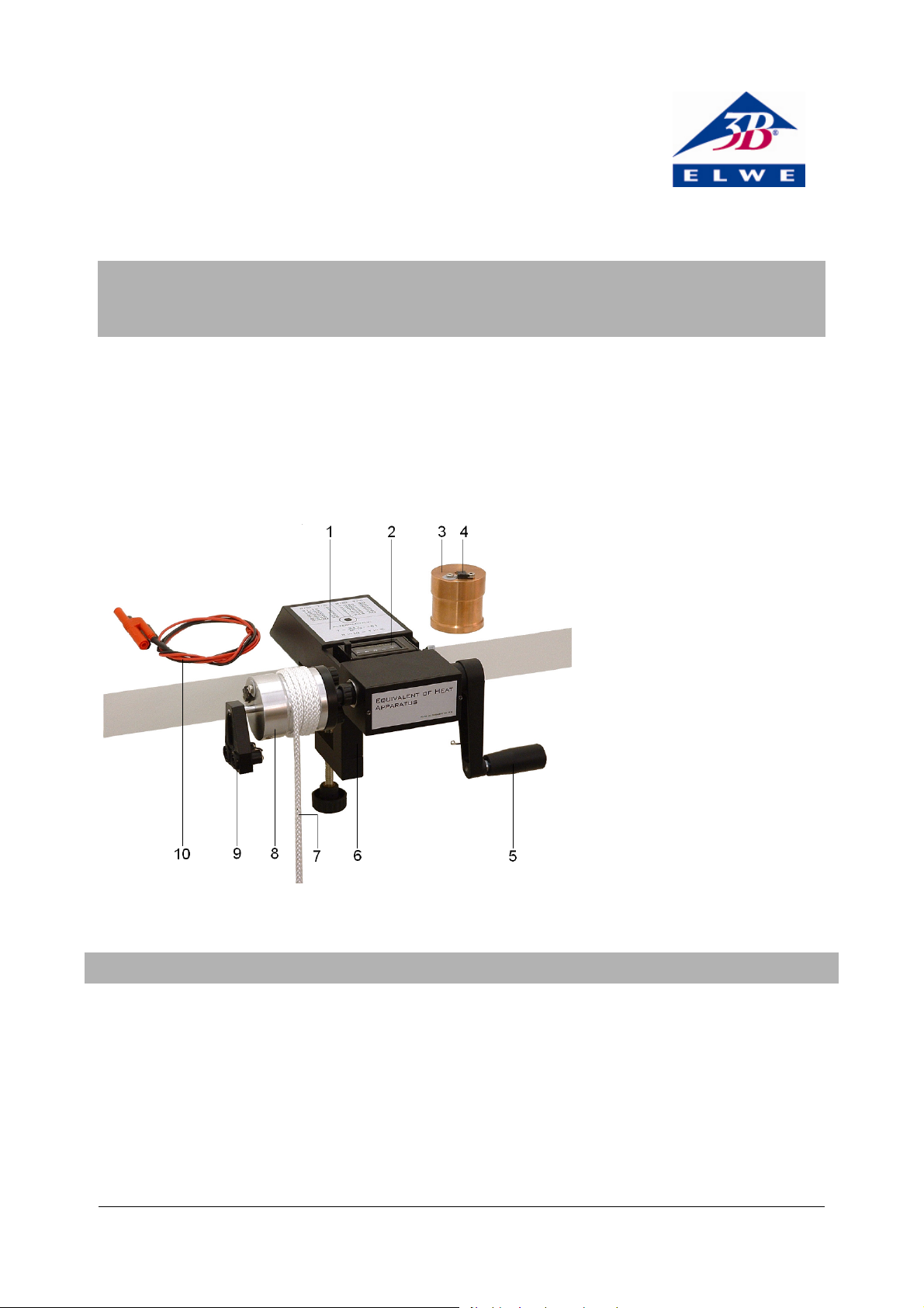
Equivalent of Heat Apparatus
Copper Cylinder
1 Base with conversion table for
resistance → temperature
2 Counter
3 Copper cylinder (1002659 /
U10366)
4 Electrical heating element
5 Hand crank
6 Table clamp
7 Friction cord with counterweight
(not visible)
8 Aluminum cylinder
9 Temperature sensor
10 Adapter cable
11 Bucket, 5 l (not shown)
Fig.1: Components
1. Safety instructions
Risk of injury! The (approx. 5 g) weight attached to the
cord (7) can cause injury to persons if it falls on them.
• It should be placed on the ground to secure it and
not be raised more than about 10 cm during the experiment.
Risk of burning! During the experiments the friction
cylinder (3 or 8) is heated.
• It should be observed that the temperature does not
rise above about 40°C. The maximum permissible
current through the heating element is 3 A and may
not be exceeded.
Risk of electric shock!
• The maximum output voltage of the power supply
used for the electric heating may not be greater
than 40 V
1
Page 2

2. Description,
The equivalent of heat apparatus can be used to show
the equivalence of mechanical work due to friction
(Nm), electrical energy (Ws) and heat (J). The values
measured in Nm or Ws agree to an accuracy of about
2%. If this equivalence is assumed, the specific heat
capacity of aluminium and copper can be determined.
The stable design with its integrated rotary counter and
a dual ball-bearing mounted shaft make experiments as
simple as possible to perform. To measure temperature
a negative temperature coefficient thermistor (NTC) is
used. This is safely contained inside an aluminium
sleeve. The aluminium sleeve snaps into the friction
cylinder so that it cannot slide out unintentionally.
3. Technical data
Technical data for the friction cylinder (approximate
values):
Diameter D: 48 mm
Height: 50 mm
Aluminum cylinder: mass m
= 250 g,
A
specific heat capacity
c
= 0,86 kJ/kg K,
A
Copper cylinder: m
= 750 g, cK = 0,41 kJ/kg K
K
Electrical connection: sockets of 2 mm diameter,
positive pole “+” isolated,
negative pole “–” connected
to ground, reversal of polarity
does not destroy the equipment
4. Operation
• The equivalent of heat apparatus is attached to a
stable workbench using its table clamp. The friction
cord is then wrapped around the friction cylinder
4½ to 5½ times with the counterweight suspended at
the rear and the loose end of the cord hanging
down at the front.
• The bucket provided can be filled with water or
sand etc. (total weight approx. 5 kg) and used as a
weight. The loose end of the friction cord is attached to the weight while the latter is resting on
the ground. It should be observed that the counterweight should be no more than about 5 cm above
the ground when the cord is taut. This prevents the
weight being raised by more than about 10 cm during the experiment.
• If it is observed that the cord moves to the right
when the crank is turned or fails to remain in its
groove, then the cord should be wrapped around
the cylinder so that the end of the cord with the
weight is on the right and that with the counterweight is on the left.
• The temperature sensor should be wetted with a
drop of oil (important!) and inserted into the selected friction cylinder according to Fig. 1 until it is
felt to snap into place and can be turned easily (if it
is inserted too far or not far enough, it is not easy to
turn it). The two connections of the temperature
sensor are attached to a resistance meter (multimeter) operating in the range 2 kΩ to 9 kΩ with a display accurate to at least three figures. The conversion of the resistance so measured into a corresponding temperature can be performed either with
the help of the conversion table on the last page of
these instructions or by using the following equation:
217
151
T
130−=,
R
(1)
where R must be given in kΩ to obtain T in °C. This
equation agrees with the table provided by the NTC
thermistor manufacturer in the range from 10 40°C to an accuracy of approximately ± 0.05°C.
• Before an experiment the friction cylinder should be
cooled to about 5 - 10°C below the ambient temperature. This can be achieved by putting it in a refrigerator or by dipping it in cold water. In the latter
case the hole for the temperature sensor should
point upwards and the cylinder may only be immersed to a depth of about 2/3 the height of the cylinder (tip: if the friction cylinder is dipped in water
inside a plastic bag, it will not need to be dried off
again when it has finished cooling).
• The rise in temperature during an experiment
should continue until the friction cylinder’s temperature has been raised to about 5 - 10°C above
the ambient temperature. The more precisely the
temperature differences for cooling and heating
(with respect to the ambient temperature) are similar, then the smaller is the net exchange of heat
with the environment.
• For heating the friction cylinder electrically, adapter
cables are provided with plugs of 2 mm diameter at
one end and conventional 4 mm lab plugs at the
other. The power should be provided by a power
supply where voltage and current limiting can be
regulated. The maximum voltage from the power
supply may not exceed 40 V. The positive pole of the
power supply is connected to the isolated socket
(identifiable due to the round, gray plate beneath
the socket) and the negative is connected to the other socket.
• The heating filaments on the friction cylinders be-
have more or less like normal ohmic resistors with a
resistance of about 11 Ω. Their maximum load ca-
pacity is about 36 W, i.e. for a max. voltage of 20 V
2
Page 3

and corresponding current of roughly 1.8 A. To set
⋅
=
⋅
=
⋅π⋅
=
⋅π⋅⋅⋅
=
=
⋅⋅⋅
⋅
(
=−⋅⋅=
Δ
(
−⋅⋅
an operating point, it is recommended that the current limit be set to exactly 1 A with voltage limited
to about 15 V. These settings cannot be altered
thereafter. Power is disconnected simply by removing the power lead until needed for the experiment.
5. Maintenance
• The equivalent of heat apparatus in principle re-
quires no maintenance. It can be wiped clean with
soap and water. Solvents should not be used. Immersion in water should also be avoided.
• The friction cylinders should be plain naked metal.
If a coating has formed on them, this can be removed using metal cleaner.
• The friction cord can be washed if necessary. For a
good value alternative, woven nylon cord can be used as a replacement.
6. Experiment procedure and evaluation
6.1 Conversion of mechanical work into heat
value. This is reached a few seconds after the end of
the experiment. After that the resistance increases
again since heat is exchanged with the environment
to cool the cylinder down to a lower temperature.
6.1.2 Experiment evaluation
Work W is defined as the product of force F and displacement s
sFW
(2)
The force of friction acting is
gmF
(3)
A
(g is the acceleration due to gravity) in the direction of
the displacement
Dns
(4)
R
• Placing Equations 3 and 4 into Equation 2 gives:
DngmW
RA
=
04575014163460819225 ,... 3386 Nm (5)
The heat stored in the friction cylinder ΔQ is determined
from the temperature difference (T
– T1) and the specific
2
heat capacity given in Section 3:
)
TTmcQ
AA
12
)
=
KJ 601426302490860 .... 3353 J (6)
6.1.1 Experiment procedure
• First the various masses are measured:
Primary weight (e.g. bucket with water) m
Counterweight (at friction cord) m
Aluminium cylinder m
• Other values to be measured in advance:
Ambient temperature T
= 0.249 kg
A
= 23.2°C
U
= 0.019 kg
G
= 5.22 kg
H
Diameter of cylinder where friction occurs
D
= 45.75 mm
R
• After cooling the cylinder, it should be screwed to
the base, the temperature sensor should be inserted
and the friction cord should be wrapped around it.
(cf. Section 4). After a few minutes, that should be
ignored for the sake of a homogenous temperature
distribution, the resistance of the temperature sensor is R
= 8,00 kΩ (corresponding to T1 = 14,60°C by
1
Eq.1).
• After zeroing the counter, the experiment is begun
by turning the crank and thus lifting the primary
weight from the ground. This slightly loosens the
cord so that it causes less friction on the cylinder.
The primary weight remains at the same height and
should remain there for the rest of the experiment.
• After n = 460 turns the experiment is halted and the
resistance value read off: R
= 3.99 kΩ (T2 = 30.26°C).
2
Since the temperature continues to rise for a short
time after the experiment is completed (homogenizing the temperature distribution), the minimum
value of the resistance is noted as the measured
In this example the disagreement between the mechanical work and the heat energy is found to be no more
than about 1%. Due to unavoidable tolerances relating
to the composition of materials (aluminium is very soft
and almost impossible to work mechanically, so that it is
always alloyed), the specific heat capacity can fluctuate
quite noticeably. The specific heat capacity is most easily
calculated by heating it electrically using the equivalence between heat and electrical energy.
6.2 Conversion of electrical energy into heat
6.2.1 Experiment procedure
• After cooling the friction cylinder it should be
screwed into the base (the same experimental conditions as for the friction experiment) and the temperature sensor inserted. After a few minutes that
should be ignored for the sake of homogenous distribution of temperature, the resistance of the temperature sensor is R
= 14.60°C by Eq. 1).
T
1
• Now the power supply that has been configured in
= 8.00 kΩ (corresponding to
1
advance (see Section 4) should be connected to the
heating element and a stopwatch started. Voltage
and current (as displayed by the power supply)
should be noted:
U = 11.4 V; I = 1.0 A
• After t = 300 s the experiment is halted and the
resistance of the sensor is read off:
R
= 3.98 kΩ (T2 = 30.32°C)
2
3
Page 4

The (slight) change in voltage is also measured:
=⋅⋅=⋅⋅=
(
=−⋅⋅=
Δ
(
−⋅⋅
Ω
U = 11.0 V.
Relationship between resistance and temperature of the temperature sensor
R / kΩ
7.86 14.97 6.78 18.19 5.70 22.05 4.62 26.84 3.54 33.10
7.84 15.03 6.76 18.26 5.68 22.13 4.60 26.94 3.52 33.24
7.82 15.08 6.74 18.32 5.66 22.21 4.58 27.04 3.50 33.38
7.80 15.14 6.72 18.39 5.64 22.29 4.56 27.14 3.48 33.51
7.78 15.19 6.70 18.45 5.62 22.37 4.54 27.24 3.46 33.65
7.76 15.25 6.68 18.52 5.60 22.45 4.52 27.35 3.44 33.79
7.74 15.31 6.66 18.58 5.58 22.53 4.50 27.45 3.42 33.93
7.72 15.36 6.64 18.65 5.56 22.61 4.48 27.55 3.40 34.07
7.70 15.42 6.62 18.72 5.54 22.69 4.46 27.66 3.38 34.22
7.68 15.47 6.60 18.78 5.52 22.77 4.44 27.76 3.36 34.36
7.66 15.53 6.58 18.85 5.50 22.85 4.42 27.87 3.34 34.50
7.64 15.59 6.56 18.92 5.48 22.94 4.40 27.97 3.32 34.65
7.62 15.64 6.54 18.99 5.46 23.02 4.38 28.08 3.30 34.79
7.60 15.70 6.52 19.05 5.44 23.10 4.36 28.18 3.28 34.94
7.58 15.76 6.50 19.12 5.42 23.19 4.34 28.29 3.26 35.09
7.56 15.81 6.48 19.19 5.40 23.27 4.32 28.40 3.24 35.24
7.54 15.87 6.46 19.26 5.38 23.35 4.30 28.51 3.22 35.39
7.52 15.93 6.44 19.33 5.36 23.44 4.28 28.62 3.20 35.54
7.50 15.99 6.42 19.40 5.34 23.52 4.26 28.72 3.18 35.69
7.48 16.05 6.40 19.46 5.32 23.61 4.24 28.83 3.16 35.84
7.46 16.10 6.38 19.53 5.30 23.69 4.22 28.95 3.14 36.00
7.44 16.16 6.36 19.60 5.28 23.78 4.20 29.06 3.12 36.15
7.42 16.22 6.34 19.67 5.26 23.87 4.18 29.17 3.10 36.31
7.40 16.28 6.32 19.74 5.24 23.95 4.16 29.28 3.08 36.47
7.38 16.34 6.30 19.81 5.22 24.04 4.14 29.39 3.06 36.63
7.36 16.40 6.28 19.88 5.20 24.13 4.12 29.51 3.04 36.79
7.34 16.46 6.26 19.95 5.18 24.21 4.10 29.62 3.02 36.95
7.32 16.52 6.24 20.03 5.16 24.30 4.08 29.74 3.00 37.11
7.30 16.57 6.22 20.10 5.14 24.39 4.06 29.85 2.98 37.28
7.28 16.63 6.20 20.17 5.12 24.48 4.04 29.97 2.96 37.44
7.26 16.69 6.18 20.24 5.10 24.57 4.02 30.09 2.94 37.61
7.24 16.75 6.16 20.31 5.08 24.66 4.00 30.20 2.92 37.78
7.22 16.81 6.14 20.39 5.06 24.75 3.98 30.32 2.90 37.94
7.20 16.88 6.12 20.46 5.04 24.84 3.96 30.44 2.88 38.11
7.18 16.94 6.10 20.53 5.02 24.93 3.94 30.56 2.86 38.29
7.16 17.00 6.08 20.60 5.00 25.02 3.92 30.68 2.84 38.46
7.14 17.06 6.06 20.68 4.98 25.11 3.90 30.80 2.82 38.63
7.12 17.12 6.04 20.75 4.96 25.21 3.88 30.92 2.80 38.81
7.10 17.18 6.02 20.83 4.94 25.30 3.86 31.04 2.78 38.99
7.08 17.24 6.00 20.90 4.92 25.39 3.84 31.17 2.76 39.17
7.06 17.30 5.98 20.97 4.90 25.48 3.82 31.29 2.74 39.35
7.04 17.37 5.96 21.05 4.88 25.58 3.80 31.42 2.72 39.53
T / °C
R / kΩ
T / °C
R / k
6.2.2 Experiment evaluation
The electrical energy E is the product of power P and
time t. The power is the product of voltage and current.
Therefore (using average voltage for the calculation):
30001211 ..tIUE 3360 Ws (7)
In this experiment, the heat added is
)
TTmcQ
AA
The agreement between E and ΔQ is very good in this
instance as well.
T / °C
R / kΩ
12
T / °C
)
=
KJ 601432302490860 .... 3366 J (8)
R / kΩ
T / °C
4
Page 5

7.02 17.43 5.94 21.12 4.86 25.67 3.78 31.54 2.70 39.71
7.00 17.49 5.92 21.20 4.84 25.77 3.76 31.67 2.68 39.90
6.98 17.55 5.90 21.28 4.82 25.86 3.74 31.79 2.66 40.08
6.96 17.62 5.88 21.35 4.80 25.96 3.72 31.92 2.64 40.27
6.94 17.68 5.86 21.43 4.78 26.05 3.70 32.05 2.62 40.46
6.92 17.74 5.84 21.50 4.76 26.15 3.68 32.18 2.60 40.65
6.90 17.81 5.82 21.58 4.74 26.25 3.66 32.31 2.58 40.84
6.88 17.87 5.80 21.66 4.72 26.34 3.64 32.44 2.56 41.04
6.86 17.93 5.78 21.74 4.70 26.44 3.62 32.57 2.54 41.23
6.84 18.00 5.76 21.81 4.68 26.54 3.60 32.70 2.52 41.43
6.82 18.06 5.74 21.89 4.66 26.64 3.58 32.84 2.50 41.63
6.80 18.13 5.72 21.97 4.64 26.74 3.56 32.97 2.48 41.83
3B Scientific GmbH • Rudorffweg 8 • 21031 Hamburg • Germany • www.3bscientific.com
Technical amendments are possible
© Copyright 2011 3B Scientific GmbH
Page 6

 Loading...