

Page 1
3B SCIENTIFIC
Instruction sheet
01/09 Hh
®
PHYSICS
Electrometer Box U11375
1. Safety instructions
The electrometer box has an extremely high
resistance at its voltage input, and can be damaged if
an excessive voltage is applied.
• Do not exceed the maximum input voltage of ±8
V!
• If necessary connect voltage-limiting components
to the input!
2. Description
The electrometer box is an impedance converter with
an extremely high input resistance for measuring very
small charges or currents.
It can be used in conjunction with the 3B NETlog
unit (U11300) for single manual measurements or
with 3B NETlab
measurements.
The electrometer box is recognised automatically by
the 3B NETlog
1 Electrometer box
1 miniDIN 8-pin connecting lead, 600 mm long
1 Instruction sheet for U11375
TM
(U11310) for recording and analysing
TM
unit..
3. Equipment supplied
TM
4. Technical data
Input resistance: > 1011 ohms
Input capacitance: <
Measurement error: <
Overvoltage tolerance for non-hazardous
contact voltages: 1 kV (for low-
10 kV (for high-resistance
Connectors: 4-mm safety sockets
• Connect the electrometer box to an analog input
of the 3B NETlog
• Short-circuit the input and calibrate the offset so
that the output reading is zero.
• Carry out the chosen experiment without delay so
that there is not time for stray charge to collect
on the input terminals.
• Before starting a new experiment short-circuit the
input again.
50 pF
1.5%
resistance sources)
sources)
5. Operation
TM
unit (input A or B).
1
Page 2
6. Examples of use
Suitable for quasi-static measurement of voltages up
to ±8 V, for high-resistance measurement of voltages
greater than ±8 V with the aid of a resistive voltage
divider, for quasi-static measurement of voltages
greater than ±8 V with the aid of a capacitive voltage
divider, for measuring very small currents with the
aid of a high-resistance shunt and for measuring very
small charges.
7. Sample experiment
Measuring charges in electrostatics
Apparatus required:
TM
1 3B NETlog
U11300
1 Electrometer box U11375
1 Faraday cup U8496460
1 Capacitor 1 nF, 160 V 1642411
2 Friction rods U11053
1 Experiment lead, black, 75 cm U13800
1 Crocodile clip 4 mm U13805
1 Cloth for rubbing rods
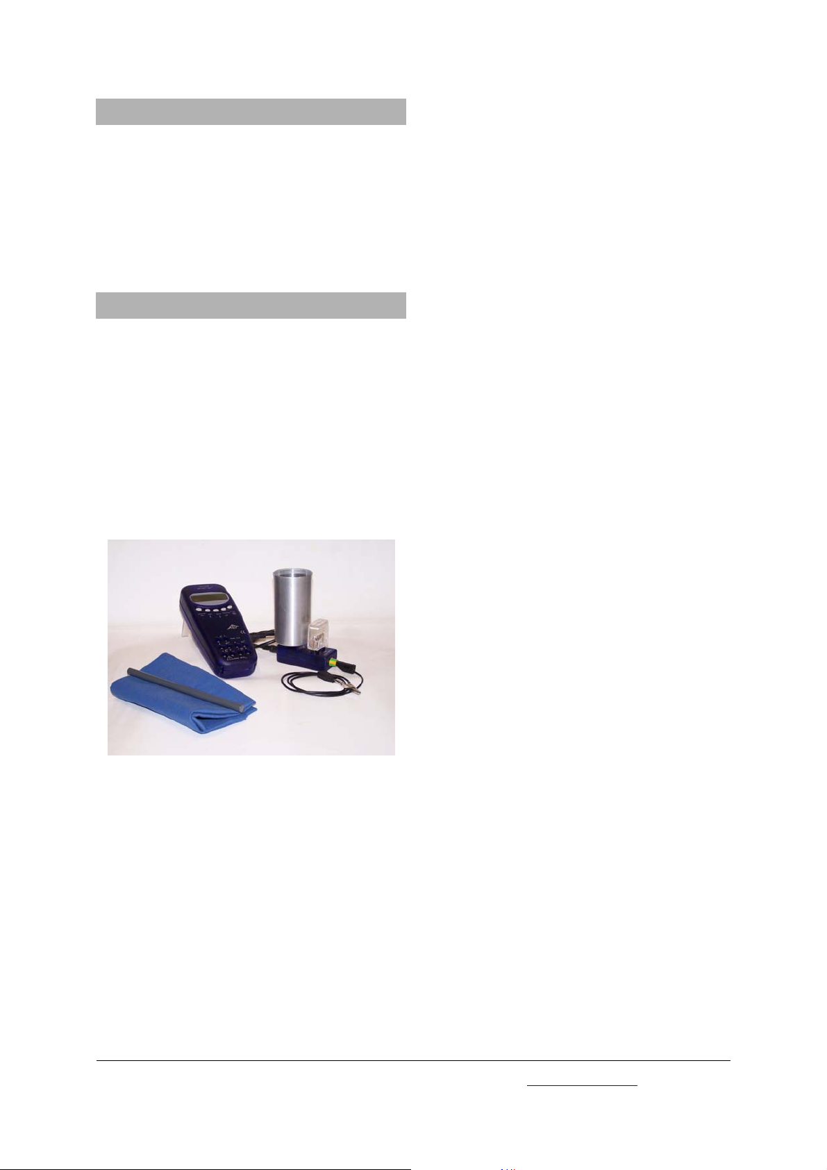
• Set up the experiment as shown in Fig. 1.
• Plug the Faraday cup and the 1 nF capacitor into
the 4 mm sockets provided.
• Plug the experiment lead into the green-and-
yellow 4 mm socket on the side of the box.
• Attach the crocodile clip to the free end of the
experiment lead.
• Switch on the 3B NETlog
TM
unit and wait for it to
detect the electrometer box.
• Hold the crocodile clip in one hand and, without
releasing it, discharge the Faraday cup.
• With the other hand lower the test object (e.g., a
friction rod that has been rubbed) into the
Faraday cup.
• Observe the effects of the charge transfer as
shown by the changes in the voltage reading on
the 3B NETlog
TM
unit.
Fig. 1 Experiment set-up for measuring charges in
electrostatics
3B Scientific GmbH • Rudorffweg 8 • 21031 Hamburg • Germany • www.3bscientific.com
© Copyright 2009 3B Scientific GmbH
Subject to technical amendments
 Loading...