

Page 1
3B SCIENTIFIC® PHYSICS
Electrolyte trough U51001
Instruction sheet
02/09 ALF
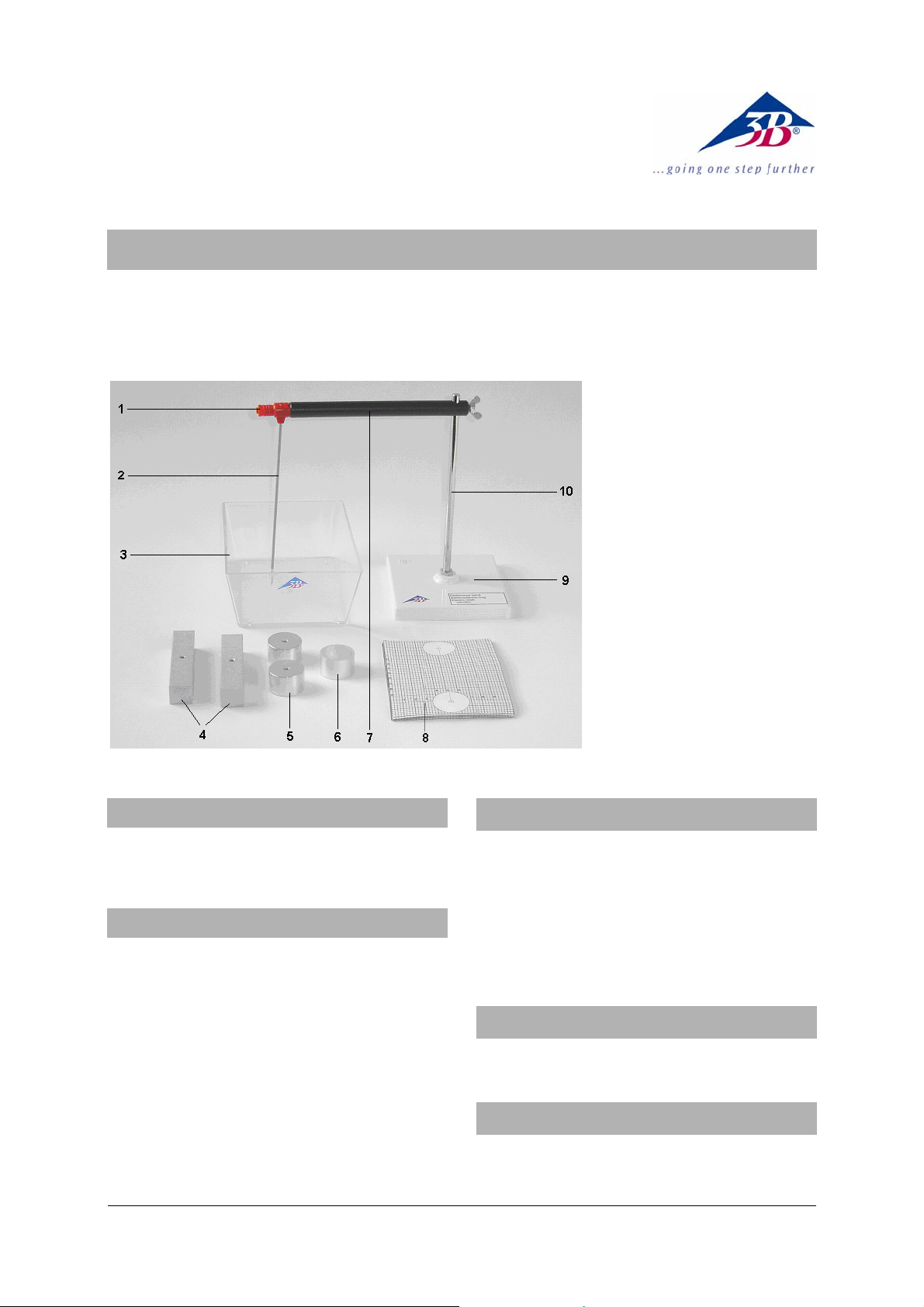
1 4-mm safety sockets
2 Measuring electrode
3 Plastic trough
4 Rod electrodes
5 Round electrodes
6 Aluminum ring
7 Insulated cross beam
8 1-millimeter squared graph
paper
9 Stand base
10 Stand rod
1. Safety instructions
• After turning on the power, do not touch the
electrodes!
2. Description
The electrolyte trough set is designed for recording
equipotential field lines of electric fields.
The electrolyte trough consists of a transparent plastic vessel (3) laid on top of 1-mm graph paper (8) and
a measuring electrode (2) mounted on a stand. The
intention is to find points with identical potential
difference. Such points are marked on a second
sheet of graph paper and joined up to form equipotential lines.
In order to show a variety of electrical fields, several
different shapes of electrode (4/5) are provided.
3. Contents
Plastic trough
1 Stand with measuring electrode
2 Rod electrodes
2 Round electrodes
1 Aluminum ring (for a Faraday cage)
20 sheets of 1-mm squared graph paper
4. Technical data
Trough dimensions: 160 mm x 105 mm
5. Principle
Electrical charges generate an electric field, the shape of which can be shown by drawing equipotential
1
Page 2
lines and surfaces. Since the potential along these
lines or surfaces is always the same, no work is performed if a charge is moved along them. The electric
field lines are always perpendicular to the lines or
surfaces of equal potential, thus it is only necessary
to determine the position of the lines by experiment
to determine the lines of the electric field. The form
that the equipotential lines take is determined by
the spatial arrangement or shape of the electric field
generated by the charges.
6. Operation
6.1 Stand assembly
• Attach the stand rod (10) to the base (9) and
secure it using the hex nut.
• Attach the insulated cross beam (7) to the stand
rod (10) using the wing nut.
• Attach the measuring electrode (2) to the cross-
beam by pushing back the connector socket (1) a
little and clamping the electrode in place.
6.2 Experiment procedure
Additionally required:
1 AC power supply (e.g. AC/DC power supply U117601)
1 Voltmeter (e.g. multimeter AM50 U17450)
4 Connector cables (75 cm)
3
400 cm
distilled water
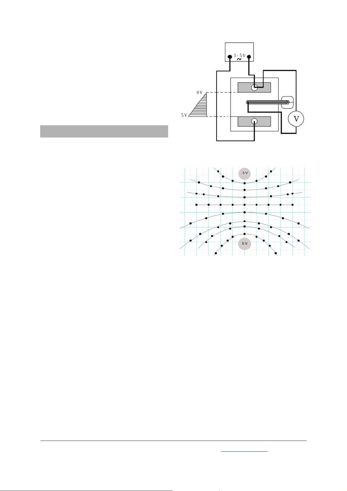
• Place the trough on a sheet of graph paper and
set up the experiment as in Fig. 1.
• Connect the power supply across both shaped
electrodes and then connect one electrode to
the measuring electrode via a voltmeter.
The voltmeter measures the potential difference
between one shaped electrode and the measuring
electrode mounted on the stand.
• Fill the trough with 400 cm
3
of distilled water so
that the shaped electrodes are covered.
• The measurement should be performed using 3
to 5 V AC to prevent deposits forming on the
electrodes.
• Turn on the power supply and use the measur-
ing electrode to locate points where the potential difference is equal.
• Trace these points on a separate sheet of graph
paper and join them together with lines.
In this way, equipotential lines can be traced forvarious electric fields generated by different-shaped
electrodes.
Fig. 1 Experiment set up
Fig. 2 Equipotential lines for point charges
3B Scientific GmbH • Rudorffweg 8 • 21031 Hamburg • Germany • www.3bscientific.com
Subject to technical amendment
© Copyright 2009 3B Scientific GmbH
 Loading...