


Vermont Casting VCPV18TP, VCPV30TP, VCBV10TN, VCBV30TP, VCBV20TP User Manual
...
Vermont Castings VCBVTN/TP & VCPVTN/TP Room Heater
INSTALLER / CONSUMER SAFETY INFORMATION
Please read this manual before installing and using appliance.
WARNING: If the information in this manual is not followed exactly, a fire or explosion may result causing property damage, personal injury of loss of life.
•Do not store or use gasoline or
other flammable vapors and liquids in the vicinity of this or any appliance.
•WHAT TO DO IF YOU SMELL GAS
•Do not try to light any appliance
•Do not touch any electrical switch; do not use any phone in your building
•Immediately call your gas supplier form a neighbor’s phone. Follow the gas supplier’s instructions
•If you cannot reach your gas supplier, call the fire department
•Installation and service must be
performed by a qualified installer, service agency or the gas supplier.
Installer: Leave this manual with the consumer.
Consumer: Retain this manual for future reference.
Unvented
Gas-Fired Room Heater
Blue Flame Heaters
Models: VCBV30TN, VCBV30TP - 30,000 Btu/Hr Thermostat
VCBV20TN, VCBV20TP - 20,000 Btu/Hr Thermostat
VCBV10TN, VCBV10TP - 10,000 Btu/Hr Thermostat
VERMONT
Castings
Plaque Heaters
Models: VCPV30TN, VCPV30TP - 30,000 Btu/Hr Thermostat
VCPV18TN, VCPV18TP - 18,000 Btu/Hr Thermostat
VCPV10TN, VCPV10TP - 10,000 Btu/Hr Thermostat
VERMONT
VERMONTCastings
Castings
User’s Operation and Installation Manual
20003770 8/02 Rev. 1
1

Vermont Castings VCBVTN/TP & VCPVTN/TP Room Heater
General Safety Information
SAFETY: Accidents are always tragic, especially |
• |
This appliance is intended for supplemental heating. |
||
because so many of them could have been prevented |
• |
Never install the heater in any of the following |
||
with a little care and judgment. There are some basic |
|
locations: |
|
|
good practices we hope you will follow for safe use of |
|
• |
Recreational vehicles |
|
your gas fired room heater. |
|
|
|
|
|
|
• Where curtains, furniture, clothing or other |
|
|
IMPORTANT: Read this user’s manual carefully and |
|
|
flammable objects are less than 36” from the |
|
completely before trying to assemble, operate or |
|
|
front, top or sides of the heater |
|
service this heater. Improper use of this heater can |
|
• |
Fireplace |
|
cause serious injury or death from burns, fire, |
|
• |
High traffic area |
|
explosion, electrical shock and carbon monoxide |
|
|
|
|
|
|
• |
Drafty areas |
|
poisoning. |
|
|
|
|
|
• |
This heater needs fresh, outside air for ventilation to |
||
Early signs of carbon monoxide poisoning resembles |
|
|
|
|
|
|
run properly. This heater has an oxygen depletion |
||
the flu, with headaches, dizziness or nausea. If you |
|
sensor (ODS) pilot light safety system. The ODS |
|
|
have these signs, the heater may not be working |
|
shuts down the heater if not enough fresh air/oxygen |
||
properly. Get fresh air at once! Have heater serviced. |
|
|
|
|
|
|
content (18%) is available. |
|
|
Some people are more affected by carbon monoxide |
|
|
|
|
|
• |
Never run heater in confined space. Refer to Page 4. |
||
than others. These include pregnant women, people |
|
|
|
|
|
• |
If heater shuts off, do not relight until you provide |
||
with heart or lung disease or anemia, those under the |
|
|
|
|
|
|
fresh, outside air. If heater keeps shutting off, have it |
||
influence of alcohol and those at high altitudes. |
|
|
|
|
|
|
serviced. |
|
|
Begin by ensuring proper installation and servicing. |
|
|
|
|
|
• |
Do not run the heater where: |
|
|
Follow the installation instructions provided with this |
|
|
|
|
|
|
• Flammable liquids or vapors are used or stored |
||
product. Have your heater installed by a qualified |
|
|
|
|
|
|
• |
Dusty condition exists |
|
technician. Have the installer show you where the gas |
|
|
|
|
|
• |
Never place any objects on the heater. |
|
|
supply shut off valve is located so that you know where |
|
|
|
|
|
• |
Supervise children when they are in the same room |
||
to shut off the gas to the heater. If the connections are |
|
|
|
|
|
|
with heater, never allow them to sit, stand or play on |
||
not perfectly seated or tightened, you may have a leak |
|
|
|
|
|
|
or around the heater. |
|
|
and therefore a faint gas smell. |
|
|
|
|
|
• |
Make sure grille guard is in place before running |
|
|
Finding a leak is not a DO-IT-YOURSELF procedure. |
|
|
|
|
|
|
heater. |
|
|
Some leaks can only be found with the main burner gas |
|
|
|
|
|
• |
Do not use heater if any part has been under water. |
||
on and this must be done by a qualified technician. |
|
|
|
|
|
|
Immediately call a qualified service technician to |
|
|
WARNING: |
|
inspect the room heater and to replace any part of |
||
|
|
the control system and any gas control which has |
||
This appliance is for use with gas referenced on |
|
been under water. |
|
|
Rating Label. Field conversion is not permitted. |
|
|
|
|
|
• |
Keep appliance area clear and free from combus- |
||
|
|
tible materials, gasoline and other flammable vapors |
||
|
|
and liquids. |
|
|
Precautions |
|
|
|
|
|
• |
Turn off heater and let cool before servicing. Only a |
||
• Never use natural gas in a unit designed for lique- |
|
qualified technician should service and repair heater. |
||
fied petroleum gases. |
|
|
|
|
• Never use liquefied petroleum gases in a unit |
|
|
|
|
designed for natural gas. |
|
Table of Contents |
||
• Check all joints and connections. To avoid the |
General Safety Information ..................................... |
2 |
||
danger of fire, accident or explosion, never check a |
Specifications .......................................................... |
3 |
||
potential gas leak with an open flame. |
Installation ............................................................... |
4 |
||
• The VCBV30, VCBV20, VCPV30 and VCPV18 |
Operating Instructions ............................................. |
8 |
||
heaters may not be installed in a bedroom or |
|
|
|
|
|
Troubleshooting .................................................... |
10 |
||
bathroom. |
|
|
|
|
|
Maintenance........................................................... |
11 |
||
• The VCBV10 and VCPV10 heaters may be |
|
|
|
|
|
Replacement Parts ................................................ |
12 |
||
installed in a bedroom, but not a bathroom. |
|
|
|
|
|
Accessories ........................................................... |
15 |
||
2
Vermont Castings VCBVTN/TP & VCPVTN/TP Room Heater
VCBVTN, VCBVTP, VCPVTN and VCPVTP Specifications
|
|
Input Rating |
Regulator |
Inlet Gas Supply |
Size |
|
||
|
Gas |
(Btu/Hr) Variable |
Pressure |
Pressure |
of Heater |
Weight |
||
Models |
Type |
Min. |
Max. |
Setting |
|
|
|
|
Min. |
Max. |
|
|
|||||
VCBV30TN |
|
15,000 |
30,000 |
|
|
|
27” x 24” x 8B\,” |
30 lbs. |
VCBV20TN |
Natural |
10,000 |
20,000 |
3.0” w.c. |
4.0” w.c. |
10.5” w.c. |
19C\,” x 22M\,” x 8Z\x” |
22 lbs. |
VCBV10TN |
|
5,000 |
10,000 |
|
|
|
15Z\x” x 20M\zn” x 7M\,” |
17 lbs. |
VCBV30TP |
|
15,000 |
30,000 |
|
|
|
27” x 24” x 8Z\x” |
30 lbs. |
VCBV20TP |
LP |
10,000 |
20,000 |
8.0” w.c. |
11.0” w.c. |
14.0” w.c. |
19C\,” x 22M\,” x 8Z\x” |
22 lbs. |
VCBV10TP |
|
5,000 |
10,000 |
|
|
|
15Z\x” x 20M\zn” x 7M\,” |
17 lbs. |
VCPV30TN |
|
6,400 |
30,000 |
|
|
|
27” X 24” X 8B\,” |
30 lbs. |
VCPV18TN |
Natural |
6,400 |
18,000 |
6.0” w.c. |
4.0” w.c. |
10.5” w.c. |
19C\,” x 22M\,” x 8Z\x” |
22 lbs. |
VCPV10TN |
|
5,500 |
10,000 |
|
|
|
15Z\x” x 20M\,” x 7M\,” |
17 lbs. |
VCPV30TP |
|
6,400 |
30,000 |
|
|
|
27” x 24” x 8Z\x” |
30 lbs. |
VCPV18TP |
LP |
6,400 |
18,000 |
10.0” w.c. |
11.0” w.c. |
14.0” w.c. |
19C\,” x 22M\,” x 8Z\x” |
22 lbs. |
VCPV10TP |
|
5,500 |
10,000 |
|
|
|
15Z\x” x 20M\,” x 7M\,” |
17 lbs. |
|
|
|
|
|
|
|
|
|
NOTES: For altitudes above 2,000 feet, reduce the input ratings (Btu/Hr) 4% for each 1,000 feet above sea level.
DO NOT USE THIS HEATER AT AN ELEVATION ABOVE 4,500 FEET.
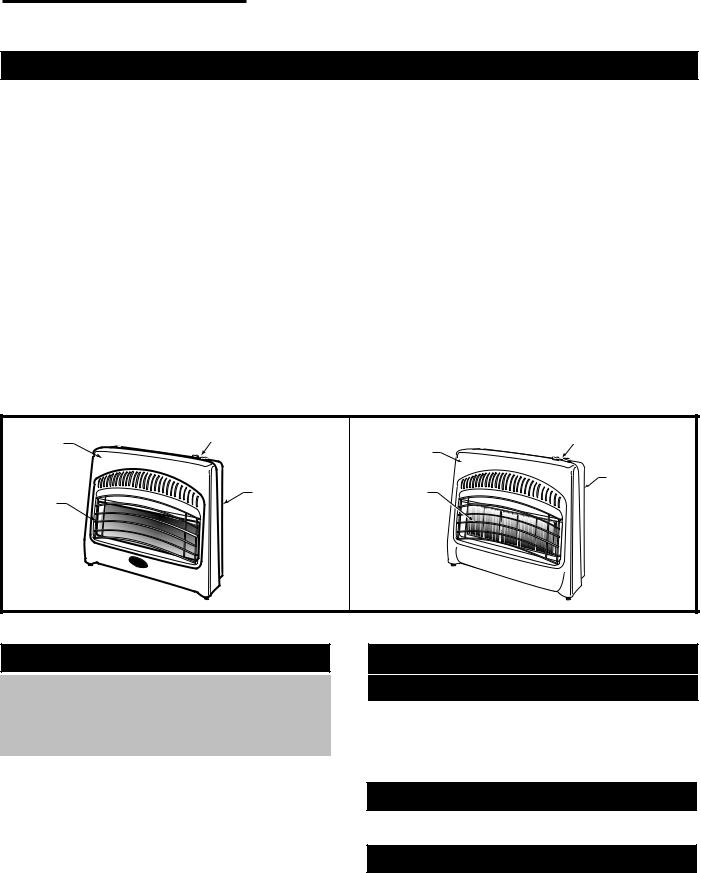
Front |
Combination |
|
|
|
Gas Control |
Front |
Combination |
||
Panel |
||||
|
||||
|
|
Panel |
Gas Control |
|
|
|
Grille |
Frame |
|
|
|
Body |
||
Grille |
Frame |
Guard |
||
Guard |
Body |
|
Assembly |
|
|
Assembly |
|
|
VERMONT
Castings
VERMONT
Castings
3771 |
3770 |
|
Fig. 1 Product identification.
Local Codes
VCBV30 / VCBV20 / VCBV10
VCPV30 / VCPV18 / VCPV10
Certified to
ANSI Z21.11.2b-2002 Unvented Heaters
Install and use heater with care. Follow all local codes. In the absence of local codes, use the latest edition of the National Fuel Gas Code ANSI Z223.1, also know as NFPA54.
Available from: |
|
American National |
National Fire Protection |
Standards Institute, Inc. |
Association, Inc. |
1430 Broadway |
Batterymarch Park |
New York, NY 10018 |
Quincy, MA 02269 |
Product Features
Safety Device
This heater has a pilot with an Oxygen Depletion Sensor shutt-off system (ODS). The ODS pilot is a required feature for vent-free heaters. The ODS pilot shuts off the heater if the normal air oxygen content is reduced to 18%.
Piezo Ignition System
This heater has a piezo ignitor. This system requires no matches, batteries or other sources to light the heater.
Thermostatic Heat Control
Thermostat has a sensing bulb, and a control valve resulting in greatest heat comfort and possible lower heating bills.
3

Vermont Castings VCBVTN/TP & VCPVTN/TP Room Heater
Installation
Installation Requirements
Fresh Air for Combustion and Ventilation
WARNING:
This heater must have fresh air for proper operation. If not, poor fuel combustion could result. Read the following instructions to insure proper fresh air for this and other fuel-burning appliances in your home.
Modern construction standards have resulted in homes that are highly energy-efficient and that allow little heat loss. Your home needs to breathe, however, and all fuel-burning appliances need fresh air to function properly and safely. Exhaust fans, clothes dryers, fireplaces and other fuel burning appliances all use the air inside the building. If the available fresh air supply is insufficient to meet the demands of these appliances, problems can result.
Provide for Adequate Ventilation
Any space within a home can be classified in these categories:
Unusually tight construction: The air that leaks around doors and windows may provide enough fresh air for combustion and ventilation. However, in buildings of unusually tight construction, you must provide additional fresh air. Unusually tight construction is defined as construction where:
Walls and ceilings exposed to the outside atmosphere have a continuous water vapor retarder with a rating of one perm or less with openings gasketed or sealed and;
Caulking or sealants are applied to areas such as joints around window and door frames, between sole plates and floors, between wall/ceiling joints, between wall panels, at penetrations for plumbing, electrical and gas lines, and at other openings.
Unconfined space: An unconfined space whose volume is not less than 50 cubic feet for each 1,000 Btu/Hr of the aggregate input rating of all appliances installed in that space. Rooms communicating directly with the space in which the appliances are installed, through openings not furnished with doors are considered a part of the unconfined space.
Confined space: A confined space whose volume is less than 50 cubic feet for each 1,000 Btu/Hr of the aggregate input rating of all appliances in that space.
WARNING: You must provide additional ventilation air in a confined space.
For proper operation of the unit, provide fresh air opening(s) to the room. Follow the National Fuel Code NFPA54/ANSI Z223.1, for required size of combustion and ventilation openings.
NOTICE: A qualified service technician should install heater. Follow all local codes.
Gas Type
Verify the type of gas supply to be used, either natural gas or LP (Propane), and make sure the marking on the appliance rating plate agrees with that of the supply gas. The rating plate is located on the side of the heater, which indicates the type of gas that the heater is orificed for.
Items Needed for Heater Installation
Before installing the heater, make sure you have these items:
•Gas piping (check local codes)
•Test gauge connection
•Sealant (resistant to LP gases) - approved thread compound
•Manual shut-off valve *
•Sediment trap - where required
•Ground joint union
•Tee joint and pipe wrench
*An installer supplied design-certified manual shut-off valve with 1/8” NPT tap connection.
Locating the Heater
This heater is designed to be mounted on a wall. The heater may also be located on the floor away from a wall. An optional floor mounting base is required and cn be purchased from your dealer.
WARNING: Never install the heater:
•in a bathroom,
•in a recreational vehicle,
•where curtains, furniture, clothing or other flammable objects are less than 36” from the front, top or sides of the heater,
•as a fireplace insert,
•in high traffic areas, or
•in windy or drafty areas.
WARNING: Vent-free heaters add moisture to the air. Although this is beneficial, installing heater in rooms without enough ventilation may cause mildew formation from too much moisture content. See National Fuel Code for Fresh Air for Combustion and Ventilation.
4
Vermont Castings VCBVTN/TP & VCPVTN/TP Room Heater
This appliance may be installed in an aftermarket* manufactured (mobile) home, where not prohibited by state or local codes.
*Aftermarket: Completion of sale, not for purpose of resale from manufacturer.
This appliance is only for use with the type of gas indicated on the rating plate. This appliance is not convertible for use with other gases.
CAUTION: If you install the heater in a home garage:
•Heater must be at least 18” above floor
•Locate heater where moving vehicle will not hit it.
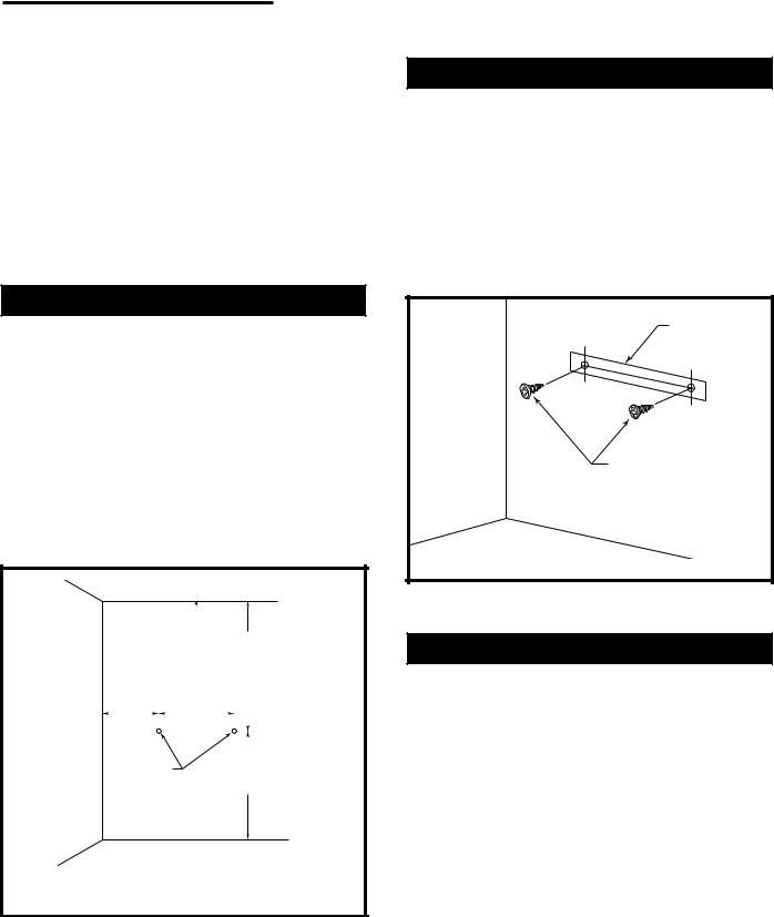
Attach Mounting Screws to Wall
NOTE: Wall anchors and mounting screws are in hardware package provided with heater.
1.Install mounting screws on wall as shown in Figure 3. Use enclosed “paper template” for proper location of holes. Be sure template is level. It may be necessary to use plastic or lead anchors for plaster walls.
2.Drill holes at marked locations using 9/64” drill bit. Insert mounting screw.
3.Leave screw head out from wall far enough to attach heater.
Preparing for Installation
1.Remove heater from carton.
2.Remove all protective packaging applied to heater for shipment.
3.Check heater for any shipping damage. If heater is damaged, promptly inform dealer/distributor.
4.Select a location for the heater that will provide maximum exposure of the radiant surface to the room, but will not be subjected to accidental contact.
5.Adequate clearance must be available around the air opening. Refer to Figure 2 for clearances that must be maintained to the side walls, floor and horizontal surface surrounding the heater.
Ceiling 
|
|
|
36" |
|
|||||
|
|
|
|
(914 mm) |
|||||
|
|
|
|
|
|
|
Min. |
||
Adjacent Wall |
|
|
|
|
|
|
|
||
13" |
|
|
A |
|
|
|
|
|
|
|
|
|
|
|
|
|
|
||
|
|
|
|
|
|
|
|||
(330 mm) |
|
|
|
|
|
|
|
|
|
Min. |
|
|
|
|
|
|
|
|
|
|
|
|
|
|
|
|
|
|
|
Screw |
|
|
|
||||||
20" |
|
||||||||
Holes |
|
(508 mm) |
|||||||
|
|
|
|
|
|
|
Min. |
||
A = 21 1/4" (330 mm) @ 30,000 Btu/ hr Model
13 11/16" (347 mm) @ 18,000/20,000 Btu/ hr Model 9 7/8" (251 mm) @ 10,000 Btu/ hr Model
RH110
Fig. 2 Minimum clearances to floor, adjacent walls and ceiling.
Template
Mounting Screws
RH101
Fig. 3 Use paper template supplied to mark location of mounting holes. Be sure template is level.
Wall Anchor Method
When mounting heater to hollow walls (wall areas between studs) or solid walls (concrete or masonry), it may be necessary to use wall anchors.
1.Place paper template on wall maintaining minimum clearance. Be sure template is level.
2.Drill holes at marked locations using 5/16” drill bit. For solid walls, concrete or masonry, drill holes at least 1” deep.
3.Insert plastic anchor. Tap anchor flush to wall. (Fig. 4)
4.Insert screw into wall anchor leaving screw head out far enough from wall to attach heater. (Fig. 4)
5.Hang heater on mounting screws in holes provided at the rear of the heater.
5
 Loading...