


 Advanced-Series
8 Channel H.264 DVR
M82600_211111E
Easy Se
A |
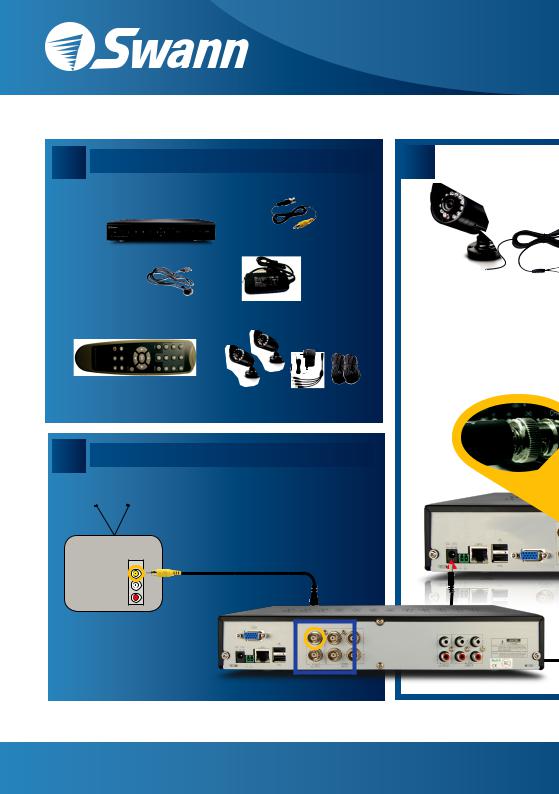
Easy Set Up Components |
|
|
or |
|
|
|
BNC to RCA Cable |
|
8ch H.264 DVR |
|
|
Power Adapter |
DVR Power |
|
Cable |
Adapter |
Remote |
|
Control |
Cameras and Accessories Optional |
C Connecting the DVR to TV
Back of TV
INPUT
3 Tune your TV to the correct INPUT - this is sometimes labelled A/V, input, source, L1, L2, etc.
- consult TV manual for details
1 Connect the RCA end of the RCA to BNC cable to the back of the TV INPUT socket
2 Connect the BNC plug end of the cable to the top
VIDEO INPUT socket on the back of the DVR
Back of DVR
B 
Cameras Optional
Swann Communications • Toll Free Technical Support: USA - 1-800-627-2799, Australia - 1300 13 8324 • Email: tech

tup Guide 8ch H.264 DVR
|
|
|
|
|
|
|
|
Camera Connections |
Connect the camera cable’s BNC |
3 |
Connect the DC power sockets on the extension |
||||||
socket & DC socket to the BNC |
cables to the power splitter’s DC plugs. |
|||||||
1 plug & DC plug on the extension cable. |
|
|
|
|||||
|
|
|
|
|
|
|
|
|
|
|
|
|
|
|
|
|
|
|
|
|
|
|
|
|
|
|
2 Connect the other end of the BNC plug of the extension cable to the camera connections on the back of the DVR.
4 Connect the power splitter’s DC socket to the DC plug on the power supply.
5 Plug in the DVR and camera power adapter to power outlets.
8-2550-2600-M13102011
@swannsecurity.com |
www. |

Before you begin
FCC Verification
NOTE: This equipment has been tested and found to comply with the limits for Class B digital device, pursuant to part 15 of the FCC Rules. These limits are designed to provide reasonable protection against harmful interference in a residential installation. This equipment generates, uses and can radiate radio frequency energy and, if not installed and used in accordance with the instructions, may cause harmful interference to radio or television reception, which can be determined by turning the equipment off and on, the user is encouraged to try to correct the interference by one or more of the following measures:
•Reorient or relocate the receiving antenna
•Increase the separation between the equipment and the receiver
•Connect the equipment into an outlet on a circuit different from that to which the receiver is
connected
•Consult the dealer or an experienced radio/TV technician for help
These devices comply with part 15 of the FCC Rules. Operation is subject to the following two conditions:
1.These devices may not cause harmful interference, and
2.These devices must accept any interference received, including interference that may cause
undesired operation.
IMPORTANT NOTE:
All jurisdictions have specific laws and regulations relating to the use of cameras. Before using any camera for any purpose, it is the buyer’s responsibility to be aware of all applicable laws and regulations that prohibit or limit the use of cameras and to comply with the applicable laws and regulations.
FCC Regulation (for USA): Prohibition against eavesdropping
Except for the operations of law enforcement officers conducted under lawful authority, no person shall use, either directly or indirectly, a device operated pursuant to the provisions of this Part for the purpose of overhearing or recording the private conversations of others unless such use is authorized by all of the parties engaging in the conversation.
WARNING
Modifications not approved by the party responsible for compliance could void user’s authority to operate the equipment.
IMPORTANT SAFETY INSTRUCTIONS
•Make sure product is fixed correctly and stable if fastened in place
•Do not operate if wires and terminals are exposed
•Do not cover vents on the side or back of the DVR and allow adequate space for ventilation
DEFAULT PASSWORD INFORMATION
To ensure your privacy, this DVR supports password protection.
•The default, all-access username is “admin”. If the DVR asks you to log in before you’ve set a password, enter admin as your username and leave the password blank. This will give you access to all areas of the DVR.
•There is no “default” password - until you set a password and enable password protection, the DVR will not ask you for one.
•To ensure your ongoing privacy, we strongly recommend setting a password as soon as possible. Choose something that you’ll remember, but that others would be unlikely to guess.
•If you do manage to lock yourself out of the DVR, you’ll need to contact us at the Swann Technical Support Telephone Helpdesk - the number is on the back cover.
2

Table of Contents
Before you begin |
2 |
Table of Contents |
3 |
Overview |
4 |
Important Information |
6 |
Layout of the Rear Panel |
7 |
Layout of the DVR4-2600 |
8 |
Layout of the DVR4-2550 |
9 |
Layout of the Remote Control |
10 |
Navigating the Menus |
12 |
Starting the DVR |
16 |
Main Menu |
18 |
Display Setup Menu |
20 |
Record Menu |
22 |
Record Setup Menu |
23 |
Manual Frame Rate Configuration |
24 |
The Recording Schedule |
25 |
Motion Detection Setup |
27 |
About Motion Detection |
28 |
Motion Detection Area Setup |
29 |
Network Menu |
30 |
Record (Video) Search |
33 |
Detail Files and Log List |
34 |
USB Backup |
35 |
Playback |
37 |
Playing Backed Up Footage on a PC |
39 |
Playing Backed Up Footage on a Mac |
41 |
Device Management |
43 |
HDD Management |
44 |
PTZ Menu |
46 |
Alarm Configuration Menu |
47 |
Auto Email Setup Menu |
49 |
System Setup Menu |
51 |
Date and Time Menu |
52 |
User Setup Menu |
54 |
Video / Audio Setup Menu |
56 |
Language Menu |
57 |
System Information Menu |
58 |
Maintain (System Maintenance) Menu |
59 |
PTZ Controls |
60 |
Remote Access |
62 |
Remote Access: Ports and UPnP |
63 |
Remote Access: IP addresses |
64 |
Remote Access via Internet Explorer |
66 |
Remote Access from a Mobile Device |
68 |
Changing or Installing the Hard Drive |
70 |
Troubleshooting |
71 |
Technical Specifications |
72 |
Warranty Information |
73 |
Helpdesk / Technical Support Details |
74 |
3

Overview
Congratulations on your purchase of this Swann DVR!
You’ve chosen a versatile, powerful and great value security monitoring and recording solution for your home or business. Let’s just take a moment to talk about some of the great features that the DVR offers and some of the things to think about before installing the system.
8 Channel Monitoring and Recording
The DVR can monitor and record eight channels simultaneously. You can configure the recording modes for each of the eight channels independently. For example, you could have four channels recording on a schedule, two recording constantly and two armed to record on motion. Or any other combination you can think of!
Powerful H.264 Compression
The advanced video codec used by the DVR, called H.264, offers high quality video files at a fraction of the size of older video codecs such as MPEG-2 or similar. Basically, this means you can store more footage on the DVR’s hard drive, and that the quality of that footage can be significantly higher than many older video formats. H.264 has been engineered to provide the highest level of data compression possible (saving space on your hard drive) whilst maintaining a high image quality.
Powerful Networking and Remote Access Features
The DVR features an Ethernet port, which can be used to connect the DVR to your local area network (LAN). With the addition of a high-speed Internet service, this allows you to remotely access the DVR from any high-speed Internet terminal on Earth! If that isn’t convenient enough, the DVR also features mobile device support, allowing you to connect to it from a device running:
•iOS (iPhone 3GS or later, iPad)
•Android (version 2.1 or higher)
•BlackBerry OS (version 5)
•Microsoft Windows Mobile® 6.1 (or higher) Professional
•Symbian (S60, 3rd or 5th edition)
Multiple Monitor Connections
Not only does the DVR come with multiple video out ports (allowing you to connect it to two televisions at once) it also comes with a VGA output, allowing you to connect the DVR to a computer monitor. The VGA connection allows for a much higher quality picture than traditional composite video connections, boasting resolutions of up to 1440 x 900 pixels.
4

Installation Tips & Tricks
One of the most important things to decide early on is where you’re going to install the DVR. There are several considerations to make, and some of them conflict with one another.
•Your DVR needs to be located in a central location to allow you maximum options when placing your cameras. This is true whether your cameras are connected via cables or wirelessly - one way, you’ll have to physically install cabling, and wireless systems still have a limited range.
•On the other hand, your DVR should be installed somewhere secure. If the DVR is too accessible it could be sabotaged or removed by an intruder.
•Ideally, assuming that you wish to use most features this DVR offers, it should be installed close to a network access point. There is, however, no problem using a long network cable - a Cat 5e Ethernet cable up to approximately three hundred feet (about 90m) should work. Different network cable standards will offer a longer or shorter range.
IMPORTANT: A note about operation
•We strongly recommend you use a USB mouse (one is included) for setup and operation of the DVR.
•Your DVR is like a small, keyboardless computer and like most computers, the fastest and easiest method for navigating through the menus and their various options is with the mouse.
•Your remote control is ideal for those times your DVR is out of arms reach.
Package Contents
DVR Unit |
Network cable |
Remote Control |
USB Mouse |
Operating Instructions |
Security Stickers (4 Pack) |
Power Adapter with Cable |
|

 Software CD
If you are missing any of these components, contact Swann Communications for assistance.
5

Important Information
IMPORTANT GUIDELINES
•Do not expose the DVR to moisture. Water is the arch-enemy of electrical components and also poses a high risk of electric shock.
•Avoid dusty locations. Dust has a tendency to build up inside the DVR case, leading to a high risk of failure or even fire.
•Only install the DVR in a well ventilated space. The circuitry and hard drive in the DVR produces a significant amount of heat, and this heat needs a way out.
•Do not open the DVR case except to install/swap the hard drive inside. There are no user serviceable parts inside.
•Never open the case whilst the DVR is plugged in, and never turn the DVR on whilst the case is open.
•Use only the supplied power adapter. Other adapters may cause damage to the DVR or cause a fire.
•Do not cut or modify any cable for any reason. Doing so will void your warranty, as well as pose a great risk of fire or electrical shock.
•Do not expose the DVR to sudden bumps or shocks (for example, being dropped). The DVR is as robust as possible, but many of the internal components are quite fragile.
•Remember that the DVR is, in all likelihood, going to be left on 24 hours a day, 7 days a week. Keep this in mind when choosing a location for installation.
Default Password Information
To ensure your privacy, this DVR supports password protection.
USERNAME: The default, all-access username is“admin”. If the DVR asks you to log in before you’ve set a password, enter admin as your username and leave the password blank. This will give you access to all areas of the DVR.
PASSWORD: There is no “default” password - until you set a password and enable password protection, the DVR will not ask you for one.
To ensure your ongoing privacy, we strongly recommend setting a password as soon as possible. Choose something that you’ll remember, but that others would be unlikely to guess.
If you do manage to lock yourself out of the DVR, you’ll need to contact us at the Swann Technical Support Telephone Helpdesk - the number is on the back cover.
6
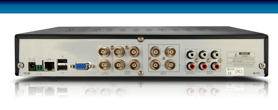
Layout of the Rear Panel
|
|
|
|
|
|
|
|
|
|
|
|
|
|
|
|
|
|
|
|
|
|
|
|
|
|
|
|
|
|
|
|
|
|
|
|
|
|
|
|
|
|
|
|
|
|
|
|
|
|
|
|
|
|
|
|
|
|
|
|
|
|
|
|
|
|
|
|
|
|
|
|
|
|
|
|
|
|
|
|
8 |
|
|
|
|
|
|
|
|
|
|
|
|
|
|
|
|
|
|
|
7 |
9 |
6 |
5 |
2 |
1 |
4 |
3 |
||||||||||||
1)CH1 ~ CH8 (Video Inputs): These are the eight camera inputs, labelled as per their channel in the DVR’s interface. Thus, plug the camera you want to be associated with Channel 1 into the port marked CH1 and so on.
2)Video Outputs: This sends a composite video signal out of the DVR. Each of the two ports can be connected to separate monitors. The output marked MAIN will show the main DVR interface (all channels accessible plus menus, unless you’ve configured the DVR to use the VGA as the main output).
3)Audio Inputs (CH1 ~ CH4): Four labelled audio inputs. These will accept standard line-level signals (<1V) and can be assigned to channels later.
4)Audio Output: Two mono audio output channels. These output a standard ‘line-level’ signal, and can easily be connected to the audio inputs on a television or stand-alone audio device.
5)VGA Output: For connection to a VGA monitor. This will display the same image as the MAIN video output at a
selectable resolution between 800 x 600, to a maximum of 1440 x 900.
6 Above) USB Mouse Port: For connecting the included USB mouse (other standard USB mice will also work). This port will not accept a USB flash drive – this port will work with a mouse only.
6 Below) USB Backup Port: For connecting a USB flash drive for the purposes of backing up footage.
7)RS485 Connections: This is the serial communication port, used primarily to connect PTZ (pan, tilt, zoom) devices.
8)Power Connection: For supplying power to the DVR. Use only the supplied power adaptor, and do NOT change or modify it in any way. Modifications to your power supply radically increases the risk of electrocution or fire, and will immediately void your warranty.
9)LAN Port: To connect an Ethernet cable, allowing the DVR to be connected to a local area network. This network, in turn, can be used to give the DVR a connection to the Internet.
7
Layout of the DVR4-2600
1 2 3 4 5 6 7 8
|
|
|
|
|
|
|
|
|
|
|
|
|
|
|
|
|
|
|
|
|
|
|
|
|
|
|
|
|
|
|
|
|
|
|
|
|
|
|
|
|
|
|
|
|
|
|
|
|
|
|
|
|
|
|
|
|
|
|
|
|
|
|
|
|
|
|
|
|
|
|
|
|
|
|
|
|
|
|
|
|
|
|
|
|
|
|
|
|
|
|
|
|
|
|
|
|
|
|
|
|
|
|
|
|
|
|
|
9 |
10 |
11 |
12 |
13 |
14 |
15 |
16 |
|
17 |
18 |
19 |
|||||||||||||||
1) Power Indicator: This LED is |
|
5) PTZ: Opens the Pan, Tilt, Zoom pop- |
||||||||||||||||||||||||
illuminated when the DVR is connected |
|
up menu. This is used to control PTZ |
||||||||||||||||||||||||
to power and switched on. |
|
|
|
capable camera systems, and will not |
||||||||||||||||||||||
2) Infrared Sensor: Monitors signals |
|
affect standard cameras. |
|
|
|
|
|
|
|
|||||||||||||||||
|
6) CH+: Moves “up” one channel. |
|
|
|||||||||||||||||||||||
coming from the infrared remote control. |
|
|
|
|||||||||||||||||||||||
If this sensor is blocked or obstructed, |
|
7) CH-: As 6, but descends one channel. |
||||||||||||||||||||||||
then the functionality of the remote will |
|
|||||||||||||||||||||||||
be impaired. |
|
|
|
8) Display (All) Mode: Enters split- |
||||||||||||||||||||||
3) Hard Drive Indicator: Lights up |
|
|||||||||||||||||||||||||
|
screen multi-view. The whole screen |
|||||||||||||||||||||||||
when the hard drive is active. It will flash |
|
is split into four or nine sections, each |
||||||||||||||||||||||||
rapidly when recording or searching (in |
|
displaying the images from one camera. |
||||||||||||||||||||||||
time with the read/write cycles). |
|
|
|
Press multiple times to cycle through all |
||||||||||||||||||||||
4) Menu/ESC: One of the primary |
|
available viewing modes. |
|
|
|
|
|
|
|
|||||||||||||||||
|
9) Rewind: During playback, this will |
|||||||||||||||||||||||||
controls for navigating through the |
|
|||||||||||||||||||||||||
menus. When in live-viewing mode, it |
|
reverse the footage. Press multiple times |
||||||||||||||||||||||||
will enter the main menu. When pressed |
|
to increase the speed of the reversing. |
||||||||||||||||||||||||
in the main menu, it will return the DVR |
|
When navigating through menus, this |
||||||||||||||||||||||||
to live-viewing mode. Finally, when in a |
|
button will move the cursor to the left. |
||||||||||||||||||||||||
submenu, this button will return you to |
|
|
|
|
|
|
|
|
|
|
|
|
|
|
|
|
|
|
|
|
||||||
the main menu. |
|
|
|
|
|
|
|
|
|
|
|
|
|
|
|
|
|
|
|
|
|
|
||||
8
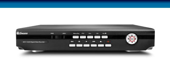
Layout of the DVR4-2550
9 |
10 |
11 |
12 |
13 |
14 |
18 |
1 2 3 |
4 |
5 |
6 |
7 |
8 |
1516 17 19
10)Pause: During playback, will pause 13) Stop: In playback mode, pressing
the current recording and leave a stillframe on screen. In live-viewing mode, this will activate the auto-sequence mode, where the display automatically cycles through the available camera signals (this must be correctly configured and enabled to function correctly).
11)Play: If pressed in live-viewing mode, this will take you directly into playback mode, and begin playing the most recent recording. In playback mode, use it to resume playback after pausing or stopping a recording.
12)Fast-Forward: During playback, this will speed up the footage. Press multiple times to increase the speed of the playback. When navigating through menus, this button will move the cursor to the right.
this button will stop playback.
14) Record: Press to immediately start recording. This acts as a manual override to the schedule and motion recording modes. For a channel to be recorded in this mode (or any other) it must listed as ‘active’ in the Camera Setup and Record Setup menus.
15 ~ 18) Arrows: Move the cursor in the selected direction in the menus.
19) Select: The equivalent of Enter/ Return on a computer keyboard. Use this button to (as the name suggests) select an option in the menus, or to confirm an entry.
9
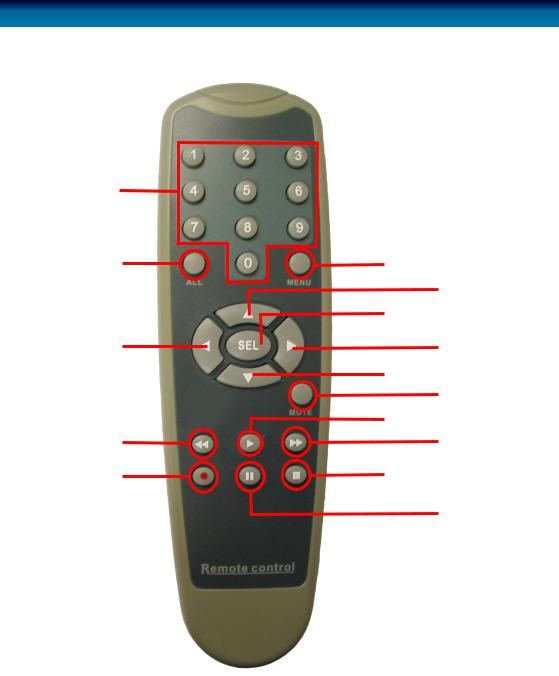
Layout of the Remote Control
1 |
|
|
|
2 |
6 |
7 |
|
|
8 |
||
3 |
9 |
||
10 |
|||
|
11 |
||
4 |
12 |
13 |
|
5 |
14 |
15 |
|
|
|
10

1)0 ~ 9 (Numeric Buttons): Used to input numbers. 1 ~ 4 can be used as quick channel changing buttons in a similar manner to a television, and these will work during either live-viewing mode or playback. Additionally, the numeric buttons will be used when inputting any numerical information – most often, your password.
2)ALL: Activates or deactivates the entire area shown on screen to be armed for Motion Detection recording mode. Motion Detection will need to be correctly configured for this button to function as described.
3, 7, 9 & 10) Arrow Buttons: Moves the cursor in the appropriate direction when navigating menus.
4)Rewind: During playback, this will reverse the footage. Press multiple times to increase the speed of the reversing.
5)Record: Press to immediately start recording. This acts as a manual override to the schedule and motion recording modes. For a channel to be recorded in this mode (or any other) it must listed as ‘active’ in the Camera Setup and Record Setup menus.
6)Menu: One of the primary controls for navigating through the menus. When in live-viewing mode, it will enter the main menu. When pressed in the main menu, it will return the DVR to live-viewing mode. Finally, when in a submenu, this button will return you to the main menu.
8) SEL (Select): The SELECT button is the equivalent of Enter/Return on a computer keyboard. Use this button to (as the name suggests) select an option in the menus, or to confirm an entry.
11)Mute: Enables or disables the audio output. This won’t have any effect on recordings - if you’ve configured the DVR to record audio, then it will continue to do so while muted - you just won’t hear it until you un-mute it!
12)Play: If pressed in live-viewing mode, this will take you directly into playback mode, and begin playing the most recent recording. In playback mode, use it to resume playback after pausing or stopping a recording.
13)Fast-Forward: During playback, this will increase the speed of playback. Press multiple times to increase the speed of playback further.
14)Stop: In playback mode, pressing this button will stop playback.
15)Pause: During playback, will pause the current recording and leave a stillframe on screen. In live-viewing mode, this will activate the auto-sequence mode, where the display automatically cycles through the available camera signals (this must be correctly configured and enabled to function correctly).
11
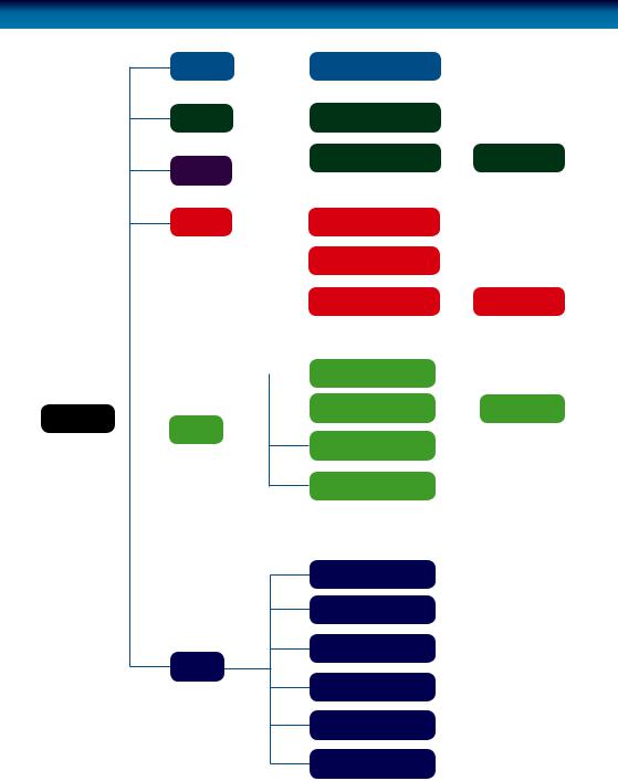
Navigating the Menus
Camera |
|
|
|
|
Color Setup |
|
|
|
|
|
|
|
|
|
|
|
|
|
|||
Record |
|
|
|
|
Record Setup |
|
|
|
Area Setup |
|
|
|
|
|
|
|
|||||
Network |
|
|
|
|
Motion |
|
|
|
||
|
|
|
|
|
|
|
||||
|
|
|
|
|
|
|
|
|
||
Search |
|
|
|
|
|
Search |
|
|
|
|
|
|
|
|
|
|
|
|
|||
|
|
|
|
|
|
Playback |
|
|
|
|
|
|
|
|
|
|
|
|
|
|
|
|
|
|
|
|
|
File Details |
|
|
|
File Details |
|
|
|
|
|
|
|
|
|
||
|
|
|
|
|
|
|
|
HDD Management |
|
|
|
|
|
|
|
|
|
|
|
|
|
Main Menu |
|
|
|
Device |
|
|
|
Alarm Config |
|
Auto Email |
|
|
|
|
|
|
|||||
|
|
|
|
|
|
|
||||
|
|
|
|
|
|
|
||||
|
|
|
|
|||||||
|
|
|
|
|
|
|
|
|||
|
|
|
|
|
|
|
||||
PTZ Settings
Mobile
Date & Time Set
User Password
Video Settings
System
Language
System Information
System Maintenance
12

There are two main ways to navigate through the menus on the DVR. One is to use the included USB mouse. This is the fastest and easiest way to navigate through the menus, make selections and input information. We highly recommend using the mouse to operate your DVR.
The other way is to use the buttons on the remote control. This is ideal for times when your DVR is not within reach or you only want to perform basic functions.
USB Mouse
When a USB mouse is attached to the DVR, it allows for easy navigation and operation of the menus. In this capacity, the mouse functions in a very similar manner to the mouse attached to a computer. The left mouse button is used to select, confirm choices and otherwise interact with the menu system. The right mouse button opens the pop-up menu (when pressed in live-viewing mode) or exits a menu (when pressed whilst in the menu system).
Remote Control
For an explanation of the functions of the buttons on the remote control, see
“Layout of the Remote Control” on page 10. Many of the controls operate in a similar manner to controls on a DVD player or similar. However, due to the specific and multi-channel nature of the DVR, the functionality of some buttons may not be immediately obvious.
IMPORTANT:
The DVR displays the menu on only one output at a time. If the DVR is not displaying the menu on the screen you have connected, press the 0 key on the remote control to swap displays.
13

Navigating the Menus
IMPORTANT - Remembering to Apply Your Changes
When you’re using the menus to change settings or values, you should click “Apply” in the bottom right corner to save your changes.
If you do not click “Apply,” a window will pop up asking whether you want to save your changes. Choose“OK”to save the changes or choose“CANCEL”to discard them.
Always select the APPLY button before leaving a menu or OK from the Save Changes dialog window upon exit if you want to save the changes that you have made.
There are two reasons why any changes to your settings must be confirmed. For one, it helps prevent accidental modification of the DVR’s settings while you’re navigating other menus or similar. Secondly, the DVR only checks and loads the settings you’ve modified when the apply button is pressed or you confirm the change upon exit. This is important to prevent the DVR operating erratically or performing an unintended operation whilst settings are in the process of being modified.
Note that the “Date and Time Menu” on page 52 will not ask you to confirm your changes. This is to prevent an incorrect time accidentally being selected, as this can have major consequences.
Using the On-Screen Keyboard
As the DVR doesn’t have a keyboard, when you have to enter text the DVR will present you an on-screen ‘keyboard’. This will automatically appear when you select a text field which allows you to enter a value.
14

Getting Started
If you’ve just unpacked your DVR and are not sure where to begin setting up your system, here’s a quick rundown of the most important things that need to be set up.
•Test your system. Before installing cables into walls, it’s a great idea to plug everything in and make sure it all works. This is particularly true if you’re using additional cameras to any that came with the DVR (this DVR is available standalone or in a kit with cameras). We do our very best to ensure that the equipment reaching you is of the highest quality and will work out of the box, but accidents do occur in shipping and sometimes components can fail. Better to find out now than once everything is screwed in place!
•Then, once the DVR is on and working, the first thing to do is to set your user access controls and passwords (see “User Setup Menu” on page 54 for details on how to do it).
•Set the Date and Time (see “Date and Time Menu” on page 52 for details) to ensure that, once you start recording, you are able to index and search the recorded footage easily. Also, if using the DVR’s footage in any legal proceedings, then having an accurate date and time on your footage becomes quite crucial.
•Check your hardware - specifically, and most importantly, the hard drive (see “HDD Management” on page 44). This is where all your footage will be stored, so it’s quite important to ensure that it is functioning correctly.
•Setup your recording modes and/or schedule (see “The Recording Schedule” on page 25) to make sure that the DVR will record what you want it to, and at the right time.
•OPTIONAL (Advanced Users): Configure your network settings (see “Network Menu” on page 30).
15
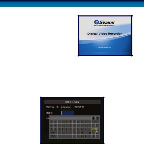
Starting the DVR
Once the DVR has been connected to power it will switch itself on automatically. The DVR takes approximately 45 seconds to boot up, during which time the image to the right will be displayed.
When you first press a button on the remote control or click a button on the mouse, the DVR may ask you to LOGIN.
To get full functionality of the DVR, enter the username admin and leave the password field blank. To change the admin password, alter user priviledges or change whether the DVR requires a secure login or not, see “User Setup Menu” on page 54.
The default mode of the DVR is live-viewing mode. This is the mode which monitors the images coming from your cameras in real-time, and allows you to configure your recording and channel options. The DVR automatically starts in live-viewing mode, with multi-view enabled.
The first thing you’ll probably open is the pop-up menu. To access the pop-up context menu, right-click anywhere on the live-viewing screen, or press the MENU / ESC button on the remote control. The pop-up menu lets you quickly access the following functions, which can be selected by left-clicking the option you want. The options are described in detail on the following page.
16
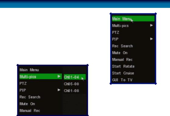
Main Menu: Opens the Main Menu of the DVR. See page 18.
PTZ: Opens the Pan, Tilt, Zoom controls. The same function can be accessed by pressing the PTZ button on the remote control.
Multi-pics: Select from all available viewing modes, and which channels you’d like to display. You can access the same options by using the viewing modes select button.
Left: The Multi-pics options. Ch01-04 and Ch05-08 will display 2 x 2 (quad) screen images of the selected channel. Ch01-08 will display all eight channels simultaneously (3 x 3, with one blank frame).
PIP (Picture In Picture): Accesses a list of available PIP modes. You can also access and cycle through these modes using the PIP button on the remote control.
RecSearch:Opens the Record (Video) Search menu, as detailed on “Record(Video)Search” onpage33.
Mute On/Off: Turns the audio on or off.
Manual Rec: Instantly engages manual recording.
Start Rotate: Initiates the automatic display rotation. Channels will be displayed sequentially on an automatic loop. To set the rotate time, see page “Video / Audio Setup Menu” on page 56. If Rotate has already been turned on, then this option will change to Stop Rotate, which will disable the rotate function.
Start Cruise: This will initiate the cruise mode for PTZ devices. You’ll need to have configured your PTZ device using the PTZ Configuration menu (page 46) and then programmed a series of preset points (see “Setting up Cruise Mode” on page 61) to use as a series of cruise movements.
Lock (only appears once a password has been set - see “User Setup Menu” on page 54): Locks the DVR’s user interface. Unlocking the DVR requires a correct username and password combination.
17
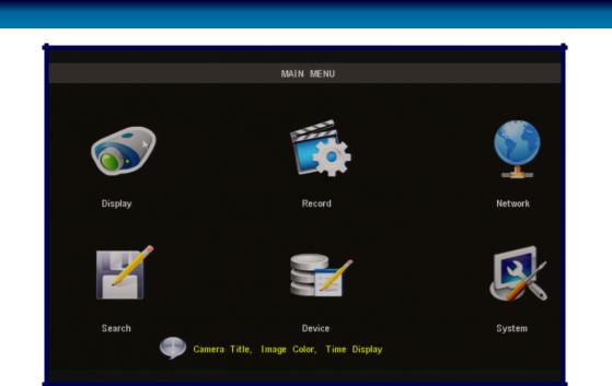
Main Menu
The MAIN MENU of the DVR. In this picture, the mouse cursor is currently highlighting the DISPLAY icon.
“Display Setup Menu” on page 20: The camera menu contains all the options for setting up how the DVR interfaces with and displays the images from the cameras connected to it. This is where channels are enabled or disabled in live viewing, and where the AUTOSEQ (Automatic Sequence) function can be configured.
Record Menu:
“Record Setup Menu” on page 23: Where you can configure the recording options for the DVR. You can set channels to be armed for recording constantly or on a schedule, and set the recording resolution, quality and size. You can also enable or disable the associated audio channel. Additionally, the recording function for some or all channels can be disabled entirely.
“About Motion Detection” on page 28: To configure how and where the DVR looks for motion. This can be used as (and is recommended as) the primary recording mode of the DVR.
18
“Network Menu” on page 30: Where you can configure the DVR to operate on your home network and over the Internet. If you want to connect to your DVR remotely using a computer or a mobile device, these settings will need to be configured correctly.
This is the most complex aspect of setting up the DVR, and requires a working knowledge of networking methods and protocols.
“Record (Video) Search” on page 33: Where you look for footage of a specific event. You only need to know the date and time that the incident that you are looking for occurred. You need not know exactly - you can specify a range of times and/ or dates. The DVR will list all recordings made in between the start and end points you specify.
“Device Management” on page 43: Here you can find the setup and configurable options for the devices which can be connected to the DVR. These devices are in order:
“HDD Management” on page 44: The hard drive, where you store your footage.
“Alarm Configuration Menu” on page 47: The circumstances which will trigger the DVR to record or issue an alert of some kind (such as an email).
“PTZ Menu” on page 46: For setting up the DVR to work with Pan, Tilt, Zoom camera systems.
“System Setup Menu” on page 51: All the remaining options and sub-menus. Here is where you set the Date and Time and your Password, change the video output settings, change languages, or the automatic maintenance schedule of the DVR.
19
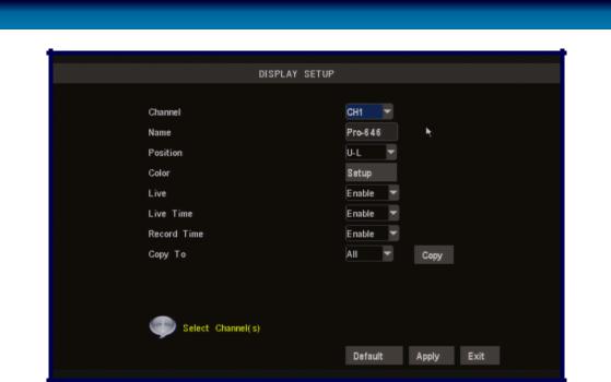
Display Setup Menu
The Display Setup menu of the DVR. In this picture, the mouse cursor is currently highlighting the CH1 title field.
Naming Channels
You can change the name of any channel from the default (and rather drab) “CHx” to anything that you would like (up to 8 characters in length). A descriptive name on each channel often makes it easier to remember what camera is where, and which channel would have captured an event you might be looking for.
Channel Name: The name that will be displayed over the image from a channel. Simply highlight this box and enter the new name you would like.
Position: Where the title of the channel is displayed on screen. You can choose any of the four corners of the display (U-L meaning Up-Left, and D-R meaning Down-Right).
20 |
Remember: After making changes to the settings press/click the APPLY button. |

Color Setup
You can fine tune the look of each channel individually by adjusting the HUE, BRIGHT (brightness), CONTRAST and SATURATION values for each channel. Just select the SETUP option under the COLOR heading to open the dialog window.
This is useful if peculiar lighting conditions, a non-standard camera or a conspicuously colored object in the frame cause the display to be inconveniently tinted, or over/ under exposed. Basically, this will help fix something that just doesn’t look ‘right’.
HUE: |
Changes the color mix of the image (this can have very dramatic |
|
results). It’s somewhat like moving through a rainbow. |
BRIGHT: |
Changes how light the image appears to be. However, it can’t make |
|
the camera see further in the dark, or increase the clarity of an ill-lit |
|
image. |
CONTRAST: |
Increasesthedifferencebetweentheblackestblackandthewhitestwhite |
|
in the image. Useful if sections of the image “grey out” but setting the |
|
contrast too high will degrade image quality. |
SATURATION: |
Alters how much color is displayed in the image. The higher the |
|
saturation, the more bright and vivid colors will appear to be. Again, |
|
setting this too high can degrade image quality. |
LIVE Viewing - Enabling and Disabling Channels
Monitoring something that you’d rather keep private/secret/unknown to the casual observer? No problems. You can alter which channels appear when in live viewing mode, and which ones appear later on.
To do so is simple: simply locate the LIVE drop down menu - it only contains two options, Enable or Disable. Simply change the value to Disable and that channel will now appear to be blank in live viewing mode. Images on the channel in question will still be recorded - and you’ll see it as normal in playback mode.
Displaying the Time
In the nearby LIVE TIME and RECORD TIME drop down menus, you can select whether you want to see the time displayed on the channel in either live viewing mode or recording, respectively. The time will always be recorded in the event list and in the footage’s meta-data (the information included in the file such as when it was recorded - you can access this later) - this simply changes whether or not you see it in the main view screen.
Remember: After making changes to the settings press/click the APPLY button. |
21 |
 Loading...