


Operator’s Manual
Rear Tine Tiller
Models
410 Thru 420 Series
IMPORTANT: Read safety rules and instructions carefully before operating equipment.
Warning: This unit is equipped with an internal combustion engine and should not be used on or near any unimproved forestcovered, brush-covered or grass-covered land unless the engine’s exhaust system is equipped with a spark arrester meeting applicable local or state laws (if any). If a spark arrester is used, it should be maintained in effective working order by the operator. In the State of California the above is required by law (Section 4442 of the California Public Resources Code). Other states may have similar laws. Federal laws apply on federal lands. A spark arrester for the muffler is available through your nearest engine authorized service dealer or contact the service department, P.O. Box 368022 Cleveland, Ohio 44136-9722.
MTD PRODUCTS INC. P.O. BOX 368022 CLEVELAND, OHIO 44136-9722
PRINTED IN U.S.A. |
FORM NO. 770-10136A.fm |
(10/99)

TABLE OF CONTENTS |
|
Content |
Page |
Important Safe Operation Practices................................................................... |
3 |
Assembling Your Tiller ....................................................................................... |
5 |
Know Your Tiller................................................................................................. |
8 |
Operating Your Tiller.......................................................................................... |
9 |
Making Adjustments .......................................................................................... |
10 |
Maintaining Your Tiller ....................................................................................... |
11 |
Service............................................................................................................... |
11 |
Off-Season Storage ........................................................................................... |
12 |
Troubleshooting................................................................................................. |
13 |
Parts List............................................................................................................ |
14 |
FINDING MODEL NUMBER
This Operator’s Manual is an important part of your new Tiller. It will help you assemble, prepare and maintain the unit for best performance. Please read and understand what it says.
Before you start assembling your new equipment, please locate the model plate on the equipment and copy the information from it in the space provided below. The information on the model plate is very important if you need help from our Customer Support Department or an authorized dealer.
•You can locate the model number by standing in the operating position behind the unit and looking down at the center of the rear tine cover. A sample model plate is explained below. For future reference, please copy the model number and the serial number of the equipment in the space below.
(Model Number) |
|
(Serial Number) |
Copy the model number here: |
|
|
|
|||
|
|
|
|
|
|
|
|
|
Copy the serial number here: |
|
MTD PRODUCTS INC |
|
||
CLEVELAND, OHIO 44136 |
|
|||
CALLING CUSTOMER SUPPORT
If you have difficulty assembling this product or have any questions regarding the controls, operation or maintenance of this unit, please call the Customer Support Department.
Call 1- (330) 220-4MTD (4683) or 1- (800)-800-7310 to reach a Customer Support representative. Please have your unit’s model number and serial number ready when you call. See previous section to locate this information. You will be asked to enter the serial number in order to process your call.
2

SECTION 1: IMPORTANT SAFE OPERATION PRACTICES
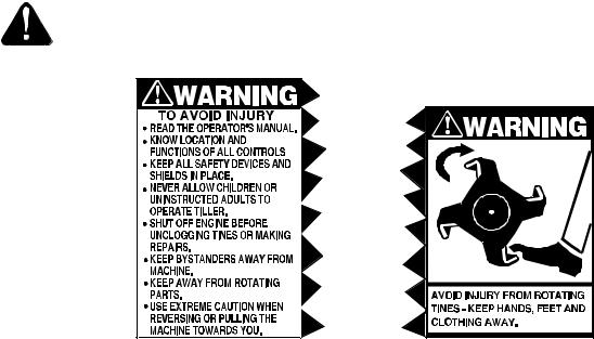
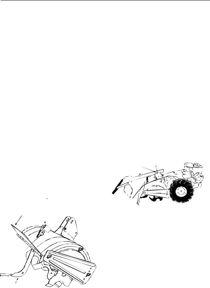
WARNING: This symbol points out important safety instructions which, if not followed, could endanger the personal safety and/or property of yourself and others. Read and follow all instructions in this manual before attempting to operate your tiller. Failure to comply with these instructions may result in personal injury. When you see this symbol— heed its warning.
WARNING: The Engine Exhaust from this product contains chemicals known to the State of California to cause cancer, birth defects or other reproductive harm.
DANGER: Your tiller was built to be operated according to the rules for safe operation in this manual. As with any type of power equipment, carelessness or error on the part of the operator can result in serious injury. This tiller is capable of amputating hands and feet. Failure to observe the following safety instructions could result in serious injury or death.
GENERAL OPERATION
•Read this operator’s manual carefully in its entirety before attempting to assemble this machine. Read, understand, and follow all instructions on the machine and in the manual(s) before operation. Be completely familiar with the controls and the proper use of the machine before operating it. Keep this manual in a safe place for future and regular reference and for ordering replacement parts.
•Your tiller is a powerful tool, not a plaything. Therefore, exercise extreme caution at all times. Your unit has been designed to perform one job: to till soil. Do not use it for any other purpose.
•Never allow children under age 14 to operate the unit. Children 14 years and older should only operate the unit under close parental supervision. Only responsible individuals who are familiar with these rules of safe operation should be allowed to use your unit.
•Do not operate tiller while under the influence of alcohol or drugs.
•Keep the area of operation clear of all persons, particularly small children and pets. Stop the engine when they are in the vicinity of your tiller.
•Wear sturdy, rough-soled work shoes and close fitting slacks and shirt. Shirt and slacks that cover the arms and legs and steel-toed shoes are recommended. Do not wear loose fitting clothes or jewelry and secure hair so it is above shoulder length. They can be caught in moving parts. Never operate a unit in bare feet, sandals or sneakers.
•Operate tiller only in daylight or good artificial light.
•Do not start tiller unless the shift lever (if provided) is in the neutral (N) position.
•Do not allow anyone to stand or walk in front of tiller when starting or running engine.
•Do not place feet or hands on or near the tines when starting the engine or while the engine is running.
•Never attempt to make depth bar, tine width, cable, handle, or wheel adjustments while the engine is running.
•Do not leave the tiller unattended with the engine running.
•Before attempting to remove rocks, bricks and other objects from tines, stop the engine and be sure the tines have stopped completely. Disconnect the spark plug wire and move it away from the spark plug.
•If your machine should start making an unusual noise or vibration, immediately stop the engine and allow the machine to come to a complete stop. Disconnect the spark plug wire and move it away from the spark plug. Take the following steps:
•Inspect for damage.
•Repair or replace any damaged parts.
•Check for any loose parts and tighten to assure continued safe operation.
•Muffler and engine become hot and can cause a burn. Do not touch.
•Keep all shields, guards and safety devices in place and operating properly.
•Use caution when tilling near fences, buildings and underground utilities. Rotating tines can cause damage or injury.
•Do not operate engine if air cleaner or cover over carburetor air intake is removed, except for adjustment. Removal of such parts could create a fire hazard.
•Only use accessories approved for this machine by the manufacturer. Read, understand, and follow all instructions provided with the approved accessory.
•If situations occur which are not covered by this manual, use care and good judgment. Contact your dealer for assistance.
3
CHILDREN
•Tragic accidents can occur if the operator is not alert to the presence of small children. Children are often attracted to the tilling activity. Never assume that children will remain where you last saw them.
•Keep children out of the work area and under the watchful eye of a responsible adult other than the operator.
•Be alert and turn the unit off if a child enters the area.
•Never allow children under the age of 14 to operate the tiller.
SERVICE
•Use extreme care in handling gasoline and other fuels. They are extremely flammable and the vapors are explosive.
•Store fuel and oil in approved containers, away from heat and open flame, and out of the reach of children. Check and add fuel before starting the engine. Never remove gas cap or add fuel while the engine is running. Allow engine to cool at least two minutes before refueling.
•Replace gasoline cap securely and wipe off any spilled gasoline before starting the engine as it may cause a fire or explosion.
•Extinguish all cigarettes, cigars, pipes and other sources of ignition.
•Never refuel unit indoors because flammable vapors will accumulate in the area.
•Never store the machine or fuel container inside where there is an open flame or spark such as a gas hot water heater, space heater, clothes dryer or furnace.
•Never run your machine in an enclosed area as the exhaust from the engine contains carbon monoxide, which is a odorless, tasteless and deadly poisonous gas.
•To reduce fire hazard, keep engine and muffler free of leaves, grass, and other debris build-up. Clean up fuel and oil spillage. Allow unit to cool at least 5 minutes before storing.
•Before cleaning, repairing, or inspecting, make certain the tines and all moving parts have stopped. Disconnect the spark plug wire and keep wire away from spark plug to prevent accidental starting. Do not use flammable solutions to clean air filter.
•We do not recommend the use of pressure washers to clean your unit. They may cause damage to electric components, spindles, pulleys, bearings or the engine. The use of pressure washers will result in shortened life and reduce serviceability.
•Keep all nuts, bolts, and screws tight to be sure the equipment is in safe working condition.
•Never tamper with safety devices. Check their proper operation regularly.
•Do not alter or tamper with the engine’s governor setting. The governor controls the maximum safe operating speed of the engine. Overspeeding the engine is dangerous and will cause damage to the engine and to other moving parts of the machine.
WARNING — YOUR RESPONSIBILITY: Restrict the use of this power machine to persons who read, understand and follow the warnings and instructions in this manual and on the machine.
4
SECTION 2: ASSEMBLING YOUR TILLER
This instruction manual covers several different model tillers. Follow only those instructions which pertain to your unit.
To Remove Unit From Carton
•Remove staples, break glue on top flaps, or cut tape at carton end and peel along top flap to open carton.
•Remove loose parts included with unit (i.e., operator’s manual, etc.).
•Cut corners and lay carton down flat.
•Remove packing material.
•Roll or slide unit out of carton. Check carton thoroughly for loose parts.
•Extend control cable and lay on the floor. Be careful not to bend or kink control cable.
IMPORTANT: The Engine is shipped WITHOUT GASOLINE or OIL. After assembly, see separate engine manual for proper fuel and engine oil recommendations.
NOTE: Left and right is determined from the operator’s position, standing behind the tiller.
Loose Parts In Carton
(1) Depth Stake
(1) Handle Assembly
(1) Shift Rod
(1) Handle Adjustment Rod (Model 420 series only)
NOTE: All hardware needed for assembly is attached to the loose parts or the tiller.
Attaching The Depth Stake Assembly
T-Knob, Flat Washer, Hex Bolt
Tine Shield
Hinge Flap
Clevis Pin
Hairpin Clip
•Tip the tiller forward so it rests on front counterweight.
•Unthread the “T” knob from the top of the depth stake, and remove the flat washer and hex bolt. Remove the hairpin clip from the clevis pin. See Figure 1.
•Raise the tine shield hinge flap assembly. Insert the depth stake assembly in the slot (under the tine shield) and up through the tine shield assembly as shown in Figure 1.
•Insert clevis pin through the tine shield and depth stake assemblies. Secure with hairpin clip.
•Insert hex bolt into the top hole of the depth stake assembly. Place flat washer on the hex bolt and thread “T” knob onto the hex bolt. See Figure 1. Tighten securely.
•Tip the tiller back down so it rests on the tines.
Attaching the Handle Assembly
•Remove the handle adjustment lock, flange nut retainer bracket, shoulder bolt and lock nut from the pivot bracket.
•Place the handle assembly in position in the handle pivot bracket lining the upper holes in the handle with the slots in the pivot bracket. See Figure 2.
Flange Nut Retainer Bracket
Shoulder Bolt
Handle Adjustment |
Lock Nut |
|
|
Lock |
|
Flange Nut |
|
Pivot Bracket
Figure 2
•Lift up the handle assembly and align the bottom holes in the handle assembly with the holes in the pivot bracket. Insert hex bolt (with hex nut retainer attached through the round hole). The head of hex bolt, flange nut retainer bracket should be to the right hand side of the unit. See Figure 3.
Depth Stake
Figure 1
5

Flange Nut Retainer Bracket |
T-Handles |
|||||
Shoulder Bolt |
|
|||||
Lock Nut |
|
|||||
Lift up |
|
|
|
Gear Shift |
||
|
|
|
|
|
||
|
|
|||||
Handle |
||||||
|
|
|
|
|
|
Rod |
|
|
|
|
|
|
|
Handle
Adjustment Rod (Model 420 series only)
Figure 5
Figure 3
•Place the hex opening of the flange nut retainer bracket over the flange nut securing the handle adjustment lock and install the lock nut on the lower shoulder bolt. See Figure 4.
Hex Hole in |
Handle Adjustment |
Retainer Bracket |
Lock |
over Flange Nut |
|
Figure 4
•Pivot handle assembly into position desired. Tighten the bottom bolt and nut securely. Tighten the handle adjustment lock.
Attaching The Gear Shift Rod
NOTE: Model 420 series tiller has two control rods. The gear shift rod is the longer rod.
•Remove the T-handle, nut, hairpin clip, flat washer and rubber washer from the end of the gear shift rod. Slide the rod up through the bracket on the front of the handle assembly (use the right hand hole for Model 420 series). See Figure 5.
•Insert the end of the gear shift rod through the opening in the top of the shift cover, and into the shift bracket. See Figure 6. Secure with rubber washer first, then flat washer and hairpin clip.
|
Gear Shift Rod |
Shift Cover |
Opening |
|

 Rubber Washer
Flat Washer
Hairpin Clip
Figure 6
•Install the nut and T-handle on the gear shift rod.
Attaching The Handle Adjustment Rod
(Model 420 series only)
|
Handle |
|
|
Adjustment |
|
|
Rod |
|
|
Positioner |
|
|
Bracket |
|
Rubber |
Hairpin |
|
Clip |
||
Washer |
||
|
Figure 7
•Remove the T-handle, nut, hairpin clip, and rubber washer from the ends of the handle adjustment rod. Slide the rod up through the left side of the bracket on the front of the handle assembly. Refer to Figure 5.
6
 Loading...