


OPERATOR'S MANUAL
46" SNOW BLADE
Model Number
190-822
IMPORTANT: READ SAFETY RULES AND INSTRUCTIONS CAREFULLY
MTD PRODUCTS INC. P.O. BOX 368022 CLEVELAND, OHIO 44136-9722
PRINTED IN U.S.A. |
FORM NO. 47448 |
RULES FOR SAFE OPERATION
Any power equipment can cause injury if operated improperly or if the user does not understand how to operate the equipment. Exercise caution at all times when operating equipment.
1.Read the tractor and snow blade owners manuals and know how to operate your tractor before using tractor with snow blade attachment.
2.Never operate tractor and snow blade without wearing proper clothing suited to weather conditions and operation of controls.
3.Never allow children to operate tractor and snow blade, and do not allow adults to operate without proper instructions.
4.Always begin with transmission in first (low) gear and gradually increase speed as required.
LOOK FOR THIS SYMBOL TO POINT OUT
IMPORTANT SAFETY PRECAUTIONS. IT
MEANS -- ATTENTION! BECOME ALERT! YOUR
SAFETY IS INVOLVED.
UNPACKING
Open carton. Remove parts and literature. Make certain all parts and literature are removed before the carton is discarded.
Lay out all parts according to the illustration below.
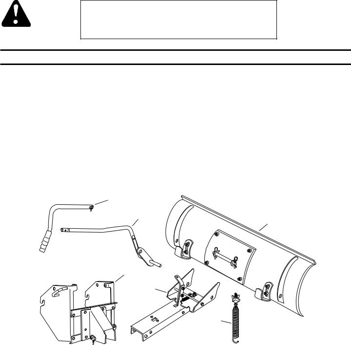
CARTON CONTENTS (Loose Parts in Carton)
A1 Upper Lift Handle w/Clevis Pin & Hairpin Clip
B1 Lower Lift Handle Assembly
C1 Hitch Assembly w/ Channel Pivot Pin & Hairpin Clips(2)
D1 Channel Assembly
E1 Blade Adjusting Spring w/Bolt, Nut, Washer & Knob
F1 Blade Assembly w/Pivot Shaft & Hairpin Clips(2)
A
B
TOOLS REQUIRED FOR ASSEMBLY
No Tools Required
F
C
D
E
2

PREPARING THE LAWN TRACTOR
B |
|
WARNING: Before beginning preparation, |
A |
|
|
|
|
F |
|
|
select a firm and level surface which is large |
C |
|
enough to accommodate the snow blade |
|
D |
|
|
|
E |
|
|
attachment and tractor. Engage brake lock. |
NOTE: When preparing the lawn tractor for assembly of snow blade attachment, store all items removed with the mowing deck.
1.Allow engine, muffler and exhaust deflector to cool before beginning.
2.Disconnect the spark plug wire(s) from the spark plug(s) and ground against the engine.
3.Remove the mowing deck as instructed in the belt removal section of the owner's manual for the lawn tractor.
SECTION 1: ASSEMBLY
INSTRUCTIONS
NOTE: Right hand (R.H.) and left hand (L.H.) are determined from the operators position while seated on the tractor.
1.To attach the hitch assembly to the front of the tractor, pull out on the attachment pins and swing the pins down clear of the holes they were in. See figure 1.
2.Hook the notches in the sides of the hitch assembly onto the shoulder bolts in the sides of the tractor frame. See figure 1.
3.To lock the hitch assembly in place, insert the attachment pins back into the holes in the hitch assembly and into the holes in the sides of the tractor frame. See figure 1.
SHOULDER BOLT
ATTACHMENT PIN
Figure 1
4.Remove the pivot shaft with hairpin clips from the welded brackets on the back of the blade. To attach the channel assembly to the blade, align the holes in the pivot plate with the holes in the welded brackets. Insert the pivot shaft through the holes, securing it with the hairpin clips.
5.Remove the plastic cap, the knob and the washer from the blade adjusting spring bolt. Adjust the hex nut on the bolt so that it is screwed approximately 1" onto the bolt threads. Hook the spring over the spring mount rod as shown. Place the bolt through the hole in the top of the blade and reassemble the washer and the knob onto the bolt. Screw the knob down until tight against the blade and the hex nut. Place the plastic cap over the end of the bolt. See figure 2.
HAIR |
BLADE |
PIN |
ADJUST |
PLASTIC |
|
SPRING |
|||
CLIP |
CAP |
||
|
|||
|
|
KNOB |
|
PIVOT |
|
WASHER |
|
SHAFT |
|
|
|
|
BOLT |
|
|
HEX |
BLADE |
|
|
|
||
|
NUT |
|
|
SPRING |
HAIRPIN CLIP |
||
MOUNT |
|||
|
|
||
ROD |
PIVOT PLATE |
|
|
|
|
||
|
Figure 2 |
|
|
6.Remove the channel pivot pin, washer and hairpin clip from the pivot support bracket. Attach the channel assembly to the tractor by placing the end of the channel inside the pivot support bracket. Insert the channel pivot pin through the holes in the pivot support bracket and the channel. Secure with the hairpin clip. See figure 3.
|
PIVOT |
|
SUPPORT |
HAIRPIN |
BRACKET |
CLIP |
|
CHANNEL
ASSEMBLY
CHANNEL
 PIVOT
PIVOT
PIN
WASHER
Figure 3
3
 Loading...