


E9490UD_EN.qx3 04.8.3 11:54 AM Page 1
OWNER’S MANUAL
MRV700VR
DIGITAL VIDEO DISC RECORDER &
VIDEO CASSETTE RECORDER
THANK YOU FOR CHOOSING MAGNAVOX.
NEED HELP FAST?
READ YOUR QUICK-USE GUIDE AND/OR OWNER’S MANUAL FIRST FOR QUICK TIPS THAT MAKE USING YOUR MAGNAVOX PRODUCT MORE ENJOYABLE. IF YOU HAVE READ YOUR INSTRUCTIONS AND STILL NEED ASSISTANCE,
YOU MAY ACCESS OUR ONLINE HELP AT WWW.MAGNAVOX.COM OR CALL 1-800-705-2000 WHILE WITH YOUR PRODUCT.
®
E9490UD_EN.qx3 04.8.3 11:54 AM Page 2
Return your Product Registration Card today to get the very most from your purchase.
Registering your model with MAGNAVOX makes you eligible for all of the valuable benefits listed below, so don't miss out. Complete and return your Product Registration Card at once to ensure:
*Proof of Purchase
Returning the enclosed card guarantees that your date of purchase will be on file, so no additional paperwork will be required from you to obtain warranty service.
*Product Safety
Notification
By registering your product, you'll receive notification - directly from the manufacturer - in the rare case of a product recall or safety defect.
*Additional Benefits
of Product Ownership
Registering your product guarantees that you'll receive all of the privileges to which you're entitled, including special money-saving offers.
Congratulations on your purchase, and welcome to the “family!”
Dear MAGNAVOX product owner:
Thank you for your confidence in MAGNAVOX. You’ve selected one of the best-built, best-backed products available today.We’ll do everything in our power to keep you happy with your purchase for many years to come.
As a member of the MAGNAVOX “family,” you’re entitled to protection by one of the most comprehensive warranties and outstanding service networks in the industry.What’s more, your purchase guarantees you’ll receive all the information and special offers for which you qualify, plus easy access to accessories from our convenient home shopping network.
Most importantly, you can count on our uncompromising commitment to your total satisfaction.
All of this is our way of saying welcome - and thanks for investing in a MAGNAVOX product.
P.S. To get the most from your MAGNAVOX purchase, be sure to complete and return your Product Registration Card at once.
Know these
safety symbols
This “bolt of lightning” indicates uninsulated t material within your unit may cause an electrical shock. For the safety of everyone in your household, please do not remove product covering.
The “exclamation point” calls attention to s features for which you should read the enclosed literature closely to prevent operating and maintenance problems.
WARNING: To reduce the risk of fire or electric shock, this apparatus should not be exposed to rain or moisture, and objects filled with liquids, such as vases, should not be placed on this apparatus.
CAUTION: To prevent electric shock, match wide blade of plug to wide slot, fully insert.
ATTENTION: Pour éviter les choc électriques, introduire la lame la plus large de la fiche dans la borne correspondante de la prise et pousser jusqu’au fond.
For Customer Use
Enter below the Serial No. which is located on the rear of the cabinet. Retain this information for future reference.
Model No. ______________________________
Serial No. ______________________________
Visit our World Wide Web Site at http://www.magnavox.com

E9490UD_EN.qx3 04.8.3 11:54 AM Page 3
Safety Information 3
Safety Precautions
Warning: To prevent fire or shock hazard, do not expose this equipment to rain or moisture.
Federal Communications Commission (FCC) Warning: Any unauthorized changes or modifications to this equipment void the user’s authority to operate it.
Laser Safety
This unit employs a laser. Only a qualified service person should remove the cover or attempt to service this device, due to possible eye injury.
CAUTION: Use of controls or adjustments or performance of procedures other than those specified herein may result in hazardous radiation exposure.The set complies with the FCC-Rules, Part 15 and with 21 CFR 1040.10. CAUTION:Visible and invisible laser radiation when open and interlock defeated. Do not stare into the beam.The beam is located inside, near the deck mechanism.
Special Information for Canadian Users
This digital apparatus does not exceed the Class B limits for radio noise emissions from digital apparatus as set out in the Radio Interference Regulations of the Canadian Department of Communications.
CET APPAREIL NUMÉRIQUE N'ÉMET PAS DE BRUITS RADIOÉLECTRIQUES DÉPASSANT LES LIMITES APPLICABLES DANS LA RÈGLEMENT SUR LE BROUILLAGE RADIOÉLECTRIQUES ÉDICTÉ PAR LE MINISTÈRE DES COMMUNICATIONS DU CANADA.
Radio/TV Interference
This equipment has been tested and found to comply with the limits for a Class B digital device, pursuant to Part 15 of the FCC Rules.These limits are designed to provide reasonable protection against harmful interference in a residential installation.This equipment generates, uses, and can radiate radio frequency energy and, if not installed and used in accordance with the instructions, may cause harmful interference to radio communications. However, there is no guarantee that interference will not occur in a particular installation. If this equipment does cause harmful interference to radio or television reception, which can be determined by turning the equipment off and on, try to correct the interference by one or more of the following measures:
1)Reorient or relocate the receiving antenna.
2)Increase the separation between the equipment and the receiver.
3)Connect the equipment into an outlet on a circuit different from that to which the receiver is connected.
4)Consult the dealer or an experienced radio/TV technician for help.
WARNING:
This device complies with Part 15 of the FCC rules. Operation is subject to the following two conditions:
1)This device may not cause harmful interference.
2)This device must accept any interference received, including interference that may cause undesired operation.
IMPORTANT:
This product was FCC verified under test conditions that included use of shielded cables and connectors between system components. Use shielded cables to reduce the possibility of causing interference to radios, televisions, and other electronic devices. If you have any problems, contact Magnavox.
Copyright Protection
Unauthorized copying, broadcasting, public performance, and lending of Discs are prohibited.This product incorporates copyright protection technology that is protected by method claims of certain U.S. patents and other intellectual property rights owned by Macrovision Corporation and other rights owners. Use of this copyright protection technology must be authorized by Macrovision Corporation and is intended for home and other limited viewing uses only unless otherwise authorized by Macrovision Corporation. Reverse engineering or disassembly is prohibited.
Notice for Progressive Scan Use: Consumers should note that not all high definition television sets are fully compatible with this product and may cause artifacts to be displayed in the picture. In case of 525 progressive scan picture problems, it is recommended that the user switch the connection to the ‘standard definition’ output. If there are questions regarding your TV set compatibility with this model 525p DVD player, please contact our customer service center.
Note to Cable TV Installer
This reminder is provided to call the Cable TV system installer’s attention to Section 820-40 of the National Electrical Code (NEC), which provides guidelines for proper grounding and, in particular, specifies that the cable ground shall be connected to the grounding system of the building, as close to the point of cable entry as practical.
Declaration of Conformity
Model Number: |
MRV700VR |
Trade Name: |
Magnavox |
Responsible Party: |
Philips Consumer Electronics |
|
P.O. Box 14810, Knoxville,TN 37914-1810 |
|
(865) 521-4316 |
E9490UD_EN.qx3 04.8.3 11:54 AM Page 4
4 Safety Information (cont’d)
IMPORTANT SAFETY INSTRUCTIONS
1.Read instructions. Read all the safety and operating instructions before operating the product.
2.Retain instructions. Keep the safety and operating instructions for future reference.
3.Heed warnings. Adhere to all warnings on the product and in the operating instructions.
4.Follow instructions. Follow all operating and use instructions.
5.Cleaning – Unplug this product from the wall outlet before cleaning. Do not use liquid cleaners or aerosol cleaners. Use a damp cloth for cleaning.
6.Attachments – Do not use attachments not recommended by the product manufacturer as they may cause hazards.
7.Water and Moisture – Do not use this product near water - for example, near a bathtub, washbowl, kitchen sink, or laundry tub, in a wet basement, near a swimming pool, etc.
8.Accessories – Do not place this product on an unstable cart, stand, tripod, bracket, or table.The product may fall, causing serious injury to a child or adult, and serious damage to the product. Use only with a cart, stand, tripod, bracket, or table recommended by the manufacturer or sold with the product. Any mounting of the product should follow the manufacturer’s instructions and should use a mounting accessory recommended by the manufacturer.
9.Move a product and cart combination with care. Quick
stops, excessive force, and uneven surfaces may cause the product and cart combination to overturn.
10.Ventilation – Slots and openings in the cabinet provide ventilation, ensure reliable operation of the product, and protect it from overheating. Do not block or cover these openings. The openings should never be blocked by placing the product on a bed, sofa, rug, or other similar surface. Do not place this product in a built-in installation such as a bookcase or rack unless proper ventilation is provided or the manufacturer’s instructions have been adhered to.
11.Power Sources – This product should be operated only from the type of power source indicated on the marking label. If you are not sure of the type of power supply to your home, consult your product dealer or local power company. For products intended to operate from battery power, or other sources, refer to the operating instructions.
12.Grounding or Polarization – This product may be equipped with a polarized alternating-current line plug (a plug having one blade wider than the other).This plug will fit into the power outlet only one way.This is a safety feature. If you are unable to insert the plug fully into the outlet, try reversing the plug. If the plug still fails to fit, contact your electrician to replace your obsolete outlet. Do not defeat the safety purpose of the polarized plug.
13.Power-Cord Protection – Route power supply cords so they are not likely to be walked on or pinched by items placed upon or against them, paying particular attention to cords at plugs, convenience receptacles, and the point where they exit from the product.
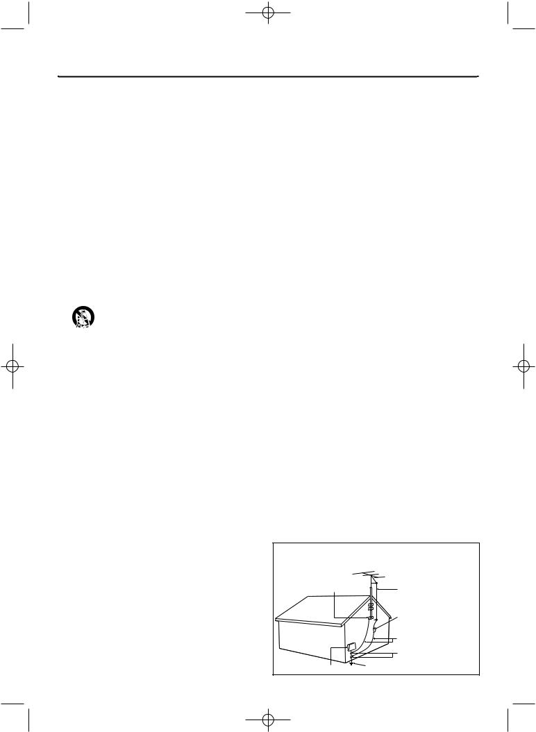
14.Outdoor Antenna Grounding – If an outside antenna or cable system is connected to the product, be sure the antenna or cable system is grounded so as to provide some protection against voltage surges and built-up static charges. Article 810 of the National Electrical Code,ANSI/NFPA 70, provides information with regard to proper grounding of the mast and supporting structure, grounding of the lead-in wire to an antenna discharge unit, size of grounding conductors, location of antenna-discharge unit, connection to grounding electrodes, and requirements for the grounding electrode. See figure at right.
15.Lightning – For added protection for this product during a lightning storm, or when it is left unattended and unused for long periods of time, unplug it from the wall outlet and disconnect the antenna or cable system.This will prevent damage to the product due to lightning and power-line surges.
16.Power Lines – An outside antenna system should not be located in the vicinity of overhead power lines or other electric light or power circuits, or where it can fall into such power lines or circuits.When installing an outside antenna system, take extreme care to keep it from touching such power lines or circuits; contact with them might be fatal.
17.Overloading – Do not overload wall outlets, extension cords, or integral convenience receptacles.This can result in a risk of fire or electric shock.
18.Object and Liquid Entry – Never push objects of any kind into this product through openings; they may touch dangerous voltage points or short out parts, resulting in a fire or electric shock. Never spill liquid of any kind on the product.
19.Servicing – Do not attempt to service this product yourself. Opening or removing covers may expose you to dangerous voltage or other hazards. Refer all servicing to qualified service personnel.
20.Damage Requiring Service – Unplug this product from the wall outlet and refer servicing to qualified service personnel under the following conditions:
a)When the power supply cord or plug is damaged,
b)If liquid has spilled or objects have fallen into the product,
c)If the product has been exposed to rain or water,
d)If the product does not operate normally by following the operating instructions. Adjust only those controls covered by the operating instructions. An improper adjustment of other controls may result in damage and will often require extensive work by a qualified technician to restore the product to its normal operation,
e)If the product has been dropped or damaged in any way,
f)When the product exhibits a distinct change in performance.This indicates a need for service.
21.Replacement Parts – When replacement parts are required, be sure the service technician uses replacement parts specified by the manufacturer or having the same characteristics as the original part. Unauthorized substitutions may result in fire, electric shock, or other hazards.
22.Safety Check – Upon completion of any service or repairs to this product, ask the service technician to perform safety checks to determine that the product is in proper operating condition.
23.Wall or Ceiling Mounting – Mount the product to a wall or ceiling only as recommended by the manufacturer.
24.Heat - Situate this product away from heat sources, such as radiators, heat registers, stoves, or other products (including amplifiers) that produce heat.
25.Battery usage CAUTION - To prevent battery leakage that may result in bodily injury, property damage, or damage to the unit:
• Install all batteries correctly, with + and - aligned as marked on the unit.
• Do not mix batteries (old/new, carbon/alkaline, etc.).
• Remove batteries when the unit is not used for a long time.
Example of Antenna Grounding
per National Electrical Code
GROUND CLAMP |
ANTENNA LEAD IN WIRE |
|
ANTENNA DISCHARGE UNIT (NEC SECTION 810-20) |
|
GROUNDING CONDUCTORS (NEC SECTION 810-21) |
|
GROUND CLAMPS |
ELECTRIC SERVICE EQUIPMENT |
POWER SERVICE GROUNDING ELECTRODE SYSTEM (NEC ART 250, PART H) |
|

E9490UD_EN.qx3 04.8.3 11:54 AM Page 5
General Information |
|
Safety Information . . . . . . . . . . . . . . . . . . . . . . . . . . . . . |
. .3-4 |
Contents . . . . . . . . . . . . . . . . . . . . . . . . . . . . . . . . . . . . |
. . . .5 |
Introduction . . . . . . . . . . . . . . . . . . . . . . . . . . . . . . . . . |
. . . .6 |
Getting Started |
|
Playable Discs . . . . . . . . . . . . . . . . . . . . . . . . . . . . . . . . |
. . . .7 |
General Information . . . . . . . . . . . . . . . . . . . . . . . . . . . |
. . . .8 |
Hookups . . . . . . . . . . . . . . . . . . . . . . . . . . . . . . . . . . . . . |
.9-17 |
Initial Setup . . . . . . . . . . . . . . . . . . . . . . . . . . . . . . . . . . . |
18-19 |
Basic Play and Recording |
|
Quick Videotape Playback . . . . . . . . . . . . . . . . . . . . . . . |
. . .20 |
Quick Disc Playback . . . . . . . . . . . . . . . . . . . . . . . . . . . |
. . .21 |
Quick Disc Recording . . . . . . . . . . . . . . . . . . . . . . . . . . |
. . .22 |
Controls |
|
Remote Control . . . . . . . . . . . . . . . . . . . . . . . . . . . . . . .23-24
Display Panel (VCR) . . . . . . . . . . . . . . . . . . . . . . . . . . . . . . .25
Front Panel . . . . . . . . . . . . . . . . . . . . . . . . . . . . . . . . . . . . .26
Rear Panel . . . . . . . . . . . . . . . . . . . . . . . . . . . . . . . . . . . . . .27
Advanced Installation |
|
TV Channel Programming . . . . . . . . . . . . . . . . . . . . . . . |
. . .28 |
VCR Plus+® Channels . . . . . . . . . . . . . . . . . . . . . . . . . . |
. . .29 |
Clock Setting . . . . . . . . . . . . . . . . . . . . . . . . . . . . . . . . . |
30-31 |
Disc Menus and Displays |
|
Menu Bars . . . . . . . . . . . . . . . . . . . . . . . . . . . . . . . . . . . . . .32
On-screen Symbols, Status Box . . . . . . . . . . . . . . . . . . . . . .33
Index Picture Screen . . . . . . . . . . . . . . . . . . . . . . . . . . . . . .34
Information Boxes . . . . . . . . . . . . . . . . . . . . . . . . . . . . . . . .35
Disc Playback Features
Title/Disc Menus, Chapter/Track Selection . . . . . . . . . . . . . .36
Audio Language, Subtitles . . . . . . . . . . . . . . . . . . . . . . . . . . .37
Zoom, Camera Angle . . . . . . . . . . . . . . . . . . . . . . . . . . . . . .38
Still Picture/Frame-by-Frame Play, Sound . . . . . . . . . . . . . . .39
Slow Motion, Searching . . . . . . . . . . . . . . . . . . . . . . . . . . . .40
Time Search, Scan . . . . . . . . . . . . . . . . . . . . . . . . . . . . . . . .41
Repeat, Repeat A-B . . . . . . . . . . . . . . . . . . . . . . . . . . . . . . .42
Disc Recording Options |
|
One-Touch Recording . . . . . . . . . . . . . . . . . . . . . . . . . . . . |
.43 |
Videotape to DVD Duplication . . . . . . . . . . . . . . . . . . . . . . |
44 |
Timer Recording (DVD mode only) . . . . . . . . . . . . . . . . . . |
45 |
VCR Plus+® Timer Recording (DVD mode only) . . . . . . . . . |
46 |
Erasing Timer Recordings . . . . . . . . . . . . . . . . . . . . . . . . . . . |
47 |
Error Messages . . . . . . . . . . . . . . . . . . . . . . . . . . . . . . . . . . |
48 |
Record One Channel/Watch Another (DVD mode) . . . . . . |
49 |
Title Settings Menu . . . . . . . . . . . . . . . . . . . . . . . . . . . . . . . |
50 |
Append Recording, Chapter Markers . . . . . . . . . . . . . . . . . . |
51 |
Record Settings . . . . . . . . . . . . . . . . . . . . . . . . . . . . . . . . . . |
52 |
Disc Editing |
|
Editing: Disc Information Screen . . . . . . . . . . . . . . . . . . . . . |
53 |
Editing . . . . . . . . . . . . . . . . . . . . . . . . . . . . . . . . . . . . . . . . . |
54 |
Finalize Disc . . . . . . . . . . . . . . . . . . . . . . . . . . . . . . . . . . . . . |
55 |
Contents 5
Additional Disc Features and Setup Options
Auto Resume, Playback Control . . . . . . . . . . . . . . . . . . |
. . .56 |
Access Control . . . . . . . . . . . . . . . . . . . . . . . . . . . . . . . . |
57-61 |
DVD Recorder Features Menu . . . . . . . . . . . . . . . . . . . |
. . .62 |
Picture Settings . . . . . . . . . . . . . . . . . . . . . . . . . . . . . . . |
. . .63 |
Digital Output . . . . . . . . . . . . . . . . . . . . . . . . . . . . . . . . |
. . .64 |
Analog Output . . . . . . . . . . . . . . . . . . . . . . . . . . . . . . . . |
. . .65 |
Language Settings . . . . . . . . . . . . . . . . . . . . . . . . . . . . . . |
. . .66 |
Night Mode, Remote Control Used . . . . . . . . . . . . . . . . |
. . .67 |
VCR Displays |
|
VCR Status Displays . . . . . . . . . . . . . . . . . . . . . . . . . . . |
. . .68 |
VCR Recording Options |
|
Videotape Recording . . . . . . . . . . . . . . . . . . . . . . . . . . . |
. . .69 |
Record One Channel/Watch Another (VCR) . . . . . . . . . |
. . .70 |
One-Touch Recording (VCR) . . . . . . . . . . . . . . . . . . . . . |
. . .71 |
Rerecording (Tape Duplication) . . . . . . . . . . . . . . . . . . . |
. . .72 |
DVD to Videotape Duplication . . . . . . . . . . . . . . . . . . . |
. . .73 |
Tape Playback Features |
|
Tape Counter . . . . . . . . . . . . . . . . . . . . . . . . . . . . . . . . |
. . .74 |
Time Search, Index Search . . . . . . . . . . . . . . . . . . . . . . . |
. . .75 |
Special Effects Playback (Videotape) . . . . . . . . . . . . . . . . |
. . .76 |
Automatic Operation Features . . . . . . . . . . . . . . . . . . . |
. . .77 |
Information You May Need |
|
Glossary . . . . . . . . . . . . . . . . . . . . . . . . . . . . . . . . . . . . . |
78-79 |
Helpful Hints . . . . . . . . . . . . . . . . . . . . . . . . . . . . . . . . . |
80-83 |
Care and Maintenance . . . . . . . . . . . . . . . . . . . . . . . . . . |
. . .84 |
Specifications . . . . . . . . . . . . . . . . . . . . . . . . . . . . . . . . . |
. . .85 |
Limited Warranty . . . . . . . . . . . . . . . . . . . . . . . . . . . . . . |
. . .86 |
Information Index . . . . . . . . . . . . . . . . . . . . . . . . . . . . . |
. . .88 |

E9490UD_EN.qx3 04.8.3 11:54 AM Page 6
6 Introduction
Welcome!
Your Magnavox DVD and Video Cassette Recorder records both DVD+RW/DVD+R and videotapes, but also plays prerecorded videotapes, DVDs and other Disc types.You can record TV programs, edit camcorder recordings, and quickly access your DVD recordings in the Index Picture Screen.You’ll soon appreciate the digital picture and sound quality of DVD, DVD+RW, and DVD+R, which will exceed the quality you have had with videotapes.
Read this manual carefully to understand the latest features, then enjoy your new DVD and Video Cassette Recorder.
DVD/VCR Features
●Channel Setup
●DVD to Videotape Duplication
●English, French, and Spanish displays
●Multi-Channel TV Sound
●OTR (One-Touch Recording)
●Videotape to DVD Duplication
VCR Features
●Automatic Head Cleaner
●19 Micron head
●Searching:Time, Index, Forward, and Reverse
●Slow Motion
DVD Features
●External Source to DVD+R/DVD+RW recording
●Fast Forward/Reverse Search
●Index Picture Screen
●NTSC/PAL compatibility
●Paused/Slow/Step-by-Step/Zoomed Play
Package Contents
●DVD and Video Cassette Recorder
●Remote control with two AA batteries
●One RF coaxial cable (black with silver tip, with single prong in center of tip)
●Still Picture
●Tape Counter
●Tracking Adjustment
●Progressive Scan compatibility
●Repeat and Repeat A-B playback
●Time Search
●Timer Recording
●VCR Plus+ Programming
●One set of Audio (red and white tips) and Video (yellow tips) cables
●This owner’s manual, a Quick-Use Guide, and registration materials
Environmental Information
Your system has materials that can be recycled and reused if disassembled by a specialized company. Please observe the local regulations regarding the disposal of packaging materials, exhausted batteries, and old equipment.
Safety Information
●Do not expose the Recorder to excessive moisture, rain, sand, or heat sources.
●Place the Recorder on a firm, flat surface.
●Keep the Recorder away from domestic heating equipment and direct sunlight.
●When placing the Recorder in a cabinet, allow about one inch of space all around the Recorder for ventilation.
Manufactured under license from Dolby Laboratories. “Dolby,” “Pro Logic,” and the double-D symbol are trademarks of Dolby Laboratories. Confidential unpublished works. Copyright 1992-1999 Dolby Laboratories. All rights reserved.
VCR Plus+ and PlusCode are registered trademarks of the Gemstar Development Corporation.The VCR Plus+ system is manufactured under license from Gemstar Development Corporation.
Copyright 2004 Philips Consumer Electronics.
E9490UD_EN.qx3 04.8.3 11:55 AM Page 7
Playable Discs 7
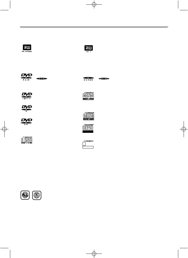
Look for these logos on your Discs to determine whether the Disc will or will not play or record on the Magnavox DVD and Video Cassette Recorder.
Discs for Recording and Playing
DVD+RW (Digital Video Disc + Rewritable): These Discs can be recorded on repeatedly. Recordings can be erased, then you can record again on the same Disc.
DVD+R (Digital Video Disc
+ Recordable): These Discs can be recorded only once. After you finalize a DVD+R, you cannot record on it or edit it any more.
Discs Unsuitable for Recording or Playing
 DVD-RAM
 DVD-Audio
Discs for Playing Only
DVD (Digital Video Disc)
DVD-R (DVD-Recordable)
You cannot record on these Discs using the Magnavox Recorder.
DVD-RW (DVD-Rewritable)
You cannot record on these Discs using the Magnavox Recorder.These Discs play only if recorded in video mode and finalized.
Audio CD
(Compact Disc Digital Audio)
Video CD (VCD)
Similar to DVDs, these Discs hold less material. For example, a two-hour movie will fit on one DVD, but may take two VCDs.
Super Video CD (SVCD)
CD-R (CD-Recordable)
Only audio and MP3 contents will play.
Recordable
CD-RW (CD-Rewritable)


 The Disc must be finalized (on your ReWritable computer or audio recorder) before
playing on the Magnavox Recorder. Only audio and MP3 contents will play.
DVD Region Codes and Color Systems
DVDs must meet the requirements for Region Codes and Color Systems before you can use them with the Recorder. DVDs must be labelled for ALL regions or for Region 1 in order to play on this DVD Recorder.You cannot play Discs that are labeled for other regions.These symbols must appear on your DVDs, or you cannot play the DVD in this Recorder.These symbols might also appear on the Disc’s case or packaging.
The number inside the globe refers to a region of the world. Region 1 represents the United States, Canada, upper regions of North America, Bermuda, the U.S.Virgin Islands, and small regions near Australia.
Furthermore, recordings are made according to different color systems throughout the world.The most common color systems are NTSC, which is used primarily in the United States and North America, PAL, and SECAM.
This Recorder is compatible with NTSC and PAL. Make sure the Discs you play were recorded in NTSC or PAL.The color system of the DVD may appear on the DVD or its case.
However, when playing a PAL Disc, the Recorder must be connected to a PAL-compatible TV using either the S-VIDEO or COMPONENT VIDEO (Y PB PR) jacks of the Recorder.The Recorder’s VIDEO jack does not send a clear PAL signal. If a PAL Disc is copy-protected, the picture may not be correct if you are using the COMPONENT VIDEO (Y PB PR) jacks.
E9490UD_EN.qx3 04.8.3 11:55 AM Page 8
8 General Information
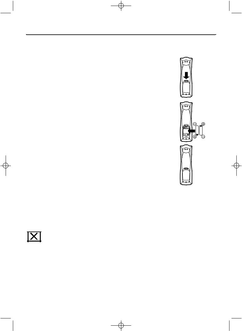
Battery Installation
1 Remove the battery compartment lid on the rear of the remote control by pressing in the tab, then lifting off the lid.
2 Place two AA batteries inside the battery compartment with their + and – ends aligned as indicated. Do not mix old and new batteries or different types of batteries (standard, alkaline, etc.).
3 Replace the battery compartment lid. You will hear it click into place.
Using the Remote Control
Unless stated otherwise, the remote control can operate all the features of the Recorder. Always point the remote control directly at the remote sensor on the front of the Recorder, not the TV. See page 26.
Make sure there are no barriers between the remote and the Recorder.
DVD Disc Menus...
Some explanations in this manual describe the DVD Disc Menus, which vary among DVDs. Movie producers set these menus, and not all DVDs have menus. But, if the DVD has a menu, access it by pressing the DISC MENU button on the remote control. See page 36.
Recorder Menus...
Some instructions explain how to use the Recorder’s System Menu or Menu Bars to set up features of the Recorder or the Disc.You get to the System Menu by pressing SYSTEM MENU on the remote control. See page 32. Even if a feature is set up in the Recorder’s menu, it will not be available if the current Disc does not include that feature.
Upgrades
If a prerecorded (store purchased) DVD does not play properly, please contact Magnavox for assistance. Due to the inconsistency of Disc formats provided by various Disc manufacturers, your Recorder may require a free playability enhancement or upgrade. As DVD technology has advanced, these enhancements have become both common and easy to complete.
Available Disc Features...
Features in this manual may not be available on every Disc. If the feature is not available, you cannot use the Recorder to make it available. An “X” will appear in the top left corner of the TV screen if you try to access a feature that is not available on the current Disc. Or, try stopping or starting play, then try the feature again. (Some features are only available during play, while others are accessible only when play is stopped.)
1
2
3

E9490UD_EN.qx3 04.8.3 11:55 AM Page 9
Hookups 9
Determining the best possible connection...
Your existing equipment, especially your TV, will determine your connection.These guidelines describe which options provide the best picture and sound quality.
Component Video provides the best picture quality. Progressive Scan Component Video has the highest quality, but use it only if the TV has
Progressive Scan. See pages 12 and 63.
S-Video provides excellent picture quality. See page 13.
Composite Video (a yellow Video jack) provides good picture quality.
See page 14.
Your TV may have only an RF-style jack, usually labeled Antenna In or 75 ohm. This may be the jack to which you have connected your Antenna or Cable TV signal already.You can use an RF coaxial cable for a simple connection. See page 10.
Digital audio connections provide the clearest sound. Connect the Recorder’s COAXIAL DIGITAL AUDIO OUT jack to your Stereo for the best sound quality. See page 16.
For the most common audio connection, connect the Recorder’s white/red AUDIO OUT L/R (left/right) jacks to the Audio In jacks of your Stereo or TV. See pages 12-15.
Before you begin...
●Refer to the manuals of your TV, Stereo, Cable Box, or other equipment as necessary. Note the jacks and connectors on the other equipment. Determine how to choose different Audio and Video In channels on your other equipment so you can see and hear the Recorder on the TV, Stereo, etc.
●Disconnect all equipment from the power outlets. Connect the equipment to the power outlets only after you have finished hooking up everything. Never make or change connections with equipment connected to the power outlet.
Remember...
●Set the TV to the correct Video In channel or channel 3.
This is channel 3 only if you connect the Recorder directly to a TV as shown on page 10.
Otherwise,Video In channels may be called AUX or AUXILIARY IN, AUDIO/VIDEO or A/V IN, EXT1 or EXT2 or External In, etc.These channels often are near TV channel zero (0). Or, your TV remote control may have a button or switch that lets you choose the Video In channel directly. See your TV manual for details. Or, go to your lowest TV channel and change channels down until you see the DVD background picture on the TV screen.
●Connect the Recorder directly to the TV. For example, do not connect the Recorder to another VCR, then connect the VCR to a TV.Your VCR may have the copy protection system, which may distort the picture and sound of a Disc or Videocassette playing on the Recorder.
●Set the Stereo to the correct channel or “source” mode.
●Do not connect the Recorder’s AUDIO OUT jacks to the PHONO IN jack of your Stereo.
●You only need one audio connection and one video connection between the Recorder and your TV (or TV and Stereo).You will not use all the jacks on the Recorder.
●You can use the Recorder to preserve your memories by copying a videotape to a DVD+R or DVD+RW. Special connections may be needed between the Recorder and your camcorder or VCR, which will play the existing videotape into the Recorder for recording. See pages 17 and 44 for details and options.
●To use the DVD or VCR features of this Recorder, you must include a connection with the supplied yellow video cable and red/white audio cables or with the supplied RF coaxial cable. See pages 10 and 14.
Once you determine the option that best fits with your existing equipment, find your choice on pages 10-16. Follow the steps for the hookup you chose.
When you finish your connections and turn on the Recorder for the first time, complete the Initial Setup.This sets up TV channels, menu languages, and other features. Go to page 18 to do the Initial Setup.
E9490UD_EN.qx3 04.8.3 11:55 AM Page 10
10 Hookups (cont’d)
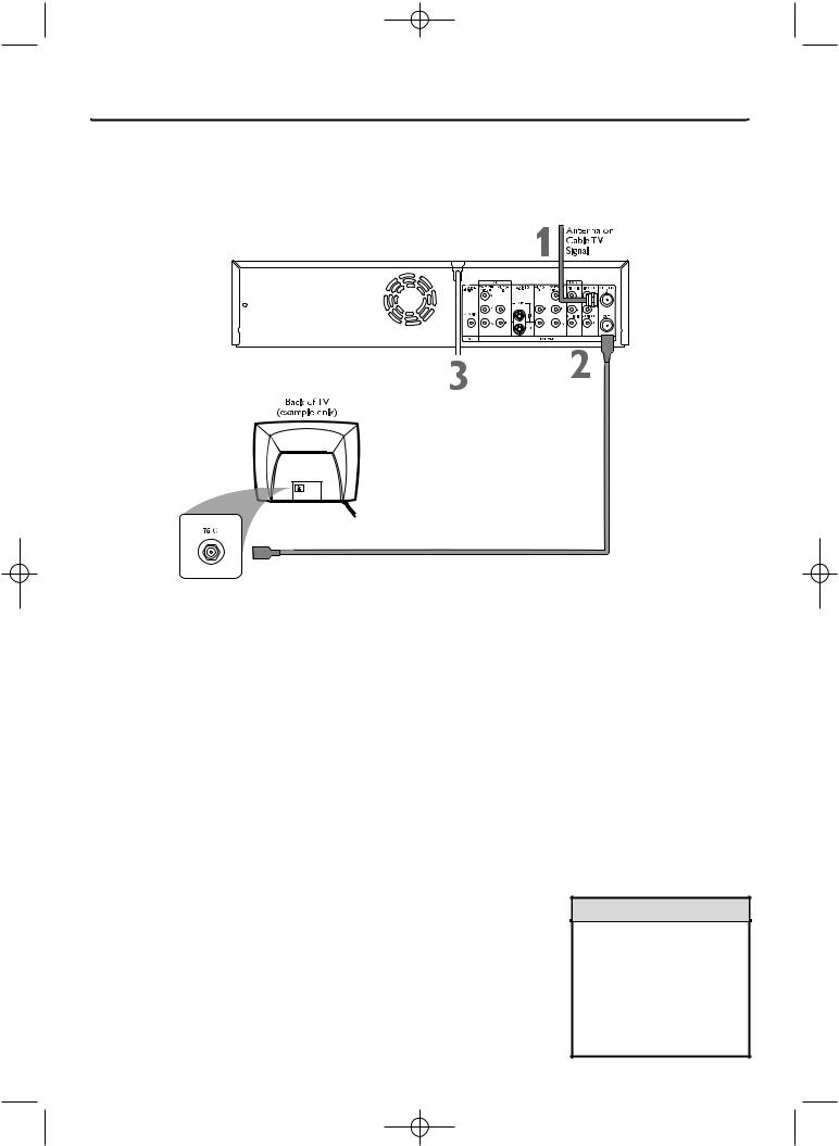
Connecting to a TV Only
TV has only an Antenna In jack
*This enables use of both VCR and DVD modes.
1 Connect your Antenna or Cable TV signal to the ANTENNA IN jack on the rear of the Recorder. Your antenna or Cable TV signal may have been connected to your TV. If so, disconnect it from the TV and connect it to the Recorder’s ANTENNA IN jack.
2 Connect the supplied RF coaxial cable to the (ANTENNA) OUT jack on the rear of the Recorder. Connect the other end of the same RF coaxial cable to the Antenna In jack on your TV. Your TV’s Antenna In jack may be labelled RF In,Antenna In, or 75 ohm. Check your TV’s manual for details.
3 Connect the power cords of the Recorder and the TV to a power outlet.
4 Press STANDBY-ON y to turn on the Recorder.
5 Turn on theTV power. Set it to channel 3. You should see the DVD background picture or the Initial Setup screen on the TV. The Initial Setup screen will appear the first time you turn on the Recorder. Go to page 18 to continue.
If channel 3 is already occupied, you may need to use channel 4 as your Recorder's output channel instead.To change the output channel to channel 4, press STANDBY-ON y to turn off the Recorder. Press DVD on the remote.Then press and hold the Number 4 button on the remote for several seconds until you see "C04" on the display panel. Now the Recorder's output channel is set to channel 4. Set your TV to channel 4. The Initial Setup screen should appear. (To go back to using channel 3 at the TV, press and hold the Number 3 button on the remote instead.)
Helpful Hint
•If “IS TV ON? C03” appears on the display panel, you need to turn on your TV and set it to channel 3.This is part of the Initial Setup.You cannot see the Initial Setup screens until you turn on the TV and have it on the correct Video In channel (channel 3 for this connection).
E9490UD_EN_v1_film.qx3 04.8.4 3:56 PM Page 11
Hookups (cont’d) 11
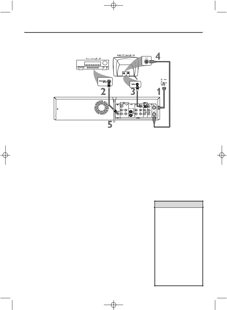
Connecting to a TV and a Cable Box or Satellite Receiver
1 Connect your Satellite or CableTV signal to the ANTENNA IN jack on your Cable Box/Satellite Receiver.
2 If your Cable Box/Satellite Receiver has a single ANTENNA OUT or TO TV jack: Connect the supplied RF coaxial cable to the ANTENNA OUT/TOTV jack of the Cable Box/Satellite Receiver and to the ANTENNA IN jack on the rear of the Recorder.
If your Cable Box/Satellite Receiver has AUDIO/VIDEO OUT jacks: Connect them to the Recorder’s EXT 2 VIDEO IN and AUDIO IN jacks.These jacks are red and white (AUDIO) and yellow (VIDEO). Use the supplied audio and video cables, which have red/white/yellow markings.
3 Connect another RF coaxial cable to the Recorder’s (ANTENNA) OUT jack and to the ANTENNA IN or RF IN jack on yourTV. Your TV’s Antenna In jack may be labelled RF In or 75 ohm. Check your TV manual for details. Or, use an Audio/Video connection between the Recorder and the TV. See pages 12-15.
4 Connect the power cords of the Recorder, Cable Box/Satellite Receiver, andTV to a power outlet.
5 Press STANDBY/ON y to turn on the Recorder. Set the Recorder to channel 3 or 4 (your Cable Box/Satellite Receiver’s output channel) if you used an RF coaxial cable to connect the Cable Box/Satellite Receiver to the Recorder.
Set the Recorder to EXT 2 if you used those jacks on the Recorder to connect to the Cable Box/Satellite Receiver.
6 Turn on theTV and the Cable Box/Satellite Receiver.
Set theTV to channel 3 to receive the picture from the Recorder (if you used the RF coaxial cable as shown for step 3).
You should see the DVD background picture or the Initial Setup screen on the TV. The Initial Setup screen will appear the first time you turn on the Recorder. Go to page 18 to continue.
Helpful Hints
•To watchTV, put the Recorder in Monitor mode and on channel 3 or 4. (Press MONITOR on the Recorder’s remote.) Change TV channels at your Cable Box or Satellite Receiver.
•If “IS TV ON? C03” appears on the display panel, you need to turn on your TV and set it to channel 3.You cannot see the Initial Setup screens until you turn on the TV and have it on the correct Video In channel.
•If channel 3 is already occupied, you may need to use channel 4 as your Recorder's output channel instead.To change the output channel to channel 4, press STANDBY-ONy to turn off the Recorder. Press DVD on the remote.Then press and hold the Number 4 button on the remote for several seconds until you see "C04" on the display panel. Now the Recorder's output channel is set to channel 4. Set your TV to channel 4. The Initial Setup screen should appear.

E9490UD_EN.qx3 04.8.3 11:55 AM Page 12
12 Hookups (cont’d)
Connecting to a TV Only
TV has Component Video In Jacks
1 Connect your Antenna or Cable TV signal to the ANTENNA IN jack on the rear of the Recorder.
2 Connect the Recorder’s COMPONENT VIDEO OUT (Y PB PR) jacks to the TV’s COMPONENT VIDEO IN jacks. Use component video cable (not supplied), which has red, blue, and green markings. Match the cable colors to the jack colors.
3 Connect the Recorder’s white/red AUDIO OUT L/R (left/right) jacks to the TV’s left/right AUDIO IN jacks. Use the supplied two-strand audio cable, which has red and white markings. Match cable colors to jack colors.
4 Connect the supplied RF coaxial cable to the Recorder’s (ANTENNA) OUT jack and to the Antenna In jack on your TV. Your TV’s Antenna In jack may be labelled RF In,Antenna In, or 75 ohm. Check your TV’s manual for details.
5 Connect the power cords of the Recorder and the TV to a power outlet.
6 Press STANDBY-ON y to turn on the Recorder. If “IS TV ON? CO3” appears on the display panel, you need to turn on your TV and set it to the correct Component Video In channel. (See next step.) You cannot see the Initial Setup screens until you turn on the TV and have it on the correct Component Video In channel.
7 Turn on the TV power. Set the TV to the Component Video In channel. It is not channel 3 or 4 when you use Component Video. See your TV owner’s manual for details. Your TV remote may have a button or switch that selects the Component Video In channel. Or, go to your lowest TV channel and change channels down until you see the DVD background picture or Initial Setup screen on the TV. The Initial Setup screen will appear the first time you turn on the Recorder. Go to page 18 to continue.
NOTE:When using the Component Video jacks, make sure Component video output is set to Interlaced. Set Component video output to Progressive Scan only if your TV has Progressive Scan. See page 63.
Helpful Hints
•If your TV has Progressive Scan, connect the Recorder’s COMPONENT VIDEO OUT (Y PB PR) jacks to the TV’s Progressive Scan In jacks instead. Progressive Scan produces a clearer picture by doubling the number of visible picture lines per field, providing a jitter-free, sharp, quiet picture. Check your TV manual for details.
Set the Recorder’s Video output to Progressive Scan. See page 63.
•On the TV, the Component Video In jacks may be labeled YUV or Pr/Cr Pb/Cb Y and may be green, blue, and red.

E9490UD_EN.qx3 04.8.3 11:55 AM Page 13
Hookups (cont’d) 13
Connecting to a TV Only
TV has an S-Video In Jack
1 Connect your Antenna or Cable TV signal to the ANTENNA IN jack on the rear of the Recorder.
2 Connect an S-Video cable (not supplied) to the Recorder’s S-VIDEO OUT jack and to the TV’s S-VIDEO In jack.
3 Connect the supplied audio cable to the Recorder’s white/red AUDIO OUT L/R (left/right) jacks and to the left/right AUDIO IN jacks on the TV. Match the cable colors to the jack colors.
4 Connect the supplied RF coaxial cable to the (ANTENNA) OUT jack on the rear of the Recorder. Connect the other end of the same RF coaxial cable to the Antenna In jack on your TV. Your TV’s Antenna In jack may be labelled RF In,Antenna In, or 75 ohm. Check your TV’s manual for details.
5 Connect the power cords of the Recorder and the TV to a power outlet.
6 Press STANDBY-ON y to turn on the Recorder. If “IS TV ON? C03” appears on the display panel, you need to turn on your TV and set it to the S- Video In channel. (See next step.) You cannot see the Initial Setup screens until you turn on the TV and have it on the correct S-Video In channel.
7 Turn on the TV power. Set the TV to the S-Video In channel. This is not channel 3 or 4 when you are using S-Video. Your TV remote may have a button or switch that selects the S-Video In channel. Or, go to your lowest TV channel and change channels down until you see the DVD background picture or Initial Setup screen on the TV. The Initial Setup screen will appear the first time
you turn on the Recorder. Go to page 18 to continue.
Helpful Hint
• On the TV, the S-Video In jack may be labeled Y/C, S-Video, or S-VHS (super video).

E9490UD_EN.qx3 04.8.3 11:55 AM Page 14
14 Hookups (cont’d)
Connecting to a TV Only
TV has a yellow Video In jack
1 Connect your Antenna or Cable TV signal to the ANTENNA IN jack on the rear of the Recorder.
2 Connect the Recorder’s yellow VIDEO OUT jack to your TV’s VIDEO IN jack. Use the supplied video cable that has yellow markings.
3 Connect the supplied audio cable to the Recorder’s white/red AUDIO OUT L/R (left/right) jacks and to the left/right AUDIO IN jacks on your TV. The supplied audio cable has red and white markings. Match the cable colors to the jack colors.
4 Connect the supplied RF coaxial cable to the (ANTENNA) OUT jack on the rear of the Recorder. Connect the other end of the same RF coaxial cable to the Antenna In jack on your TV. Your TV’s Antenna In jack may be labelled RF In,Antenna In, or 75 ohm. Check your TV manual for details.
5 Connect the power cords of the Recorder and the TV to a power outlet.
6 Press STANDBY-ON y to turn on the Recorder.
If “IS TV ON? CO3” appears on the display panel, you need to turn on your TV and set it to the correct Video In channel. (See next step.) You cannot see the Initial Setup screens until you turn on the TV and have it on the correct Video In channel.
7 Turn on the TV power. Set the TV to the correct Audio/Video In channel. Such channels may be called AUX or AUXILIARY IN, AUDIO/VIDEO or A/V IN, EXT1 or EXT2 or External In, etc. This is not channel 3 or 4. See your TV manual. Your TV remote may have a button or switch that selects the Video In channel. Or, go to your lowest TV channel and change channels down until you see the DVD background picture or Initial Setup screen. The Initial Setup screen will appear the first time you turn on the Recorder. Go to page 18 to continue.
Helpful Hint
•The TV’s Video In jack is usually yellow. It may be labeled video, CVBS, composite, or baseband.
E9490UD_EN.qx3 04.8.3 11:55 AM Page 15
Hookups (cont’d) 15
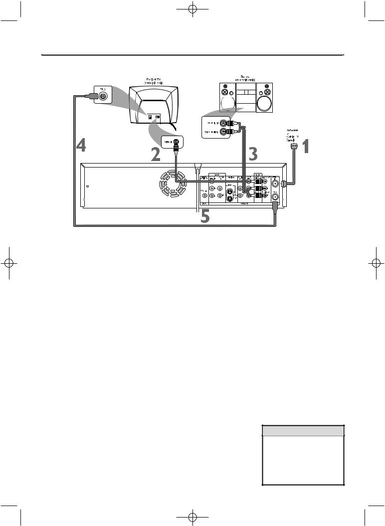
Connecting to a TV and a Stereo
1 Connect your Antenna or Cable TV signal to the ANTENNA IN jack on the rear of the Recorder.
2 Connect the Recorder’s yellow VIDEO OUT jack to your TV’s VIDEO IN jack. Use the supplied video cable that has yellow markings.
3 Connect the supplied audio cable to the Recorder’s white/red AUDIO OUT L/R (left/right) jacks and to the left/right AUDIO IN jacks on the Stereo. The audio cable has red and white markings. Match the cable colors to the jack colors.
4 Connect the supplied RF coaxial cable to the (ANTENNA) OUT jack on the rear of the Recorder. Connect the other end of the same RF coaxial cable to the Antenna In jack on your TV. Your TV’s Antenna In jack may be labelled RF In,Antenna In, or 75 ohm. Check your TV manual for details.
5 Connect the power cords of the Recorder, Stereo, and TV to a power outlet.
6 Turn on the Stereo and set it to the correct Audio In channel or sound source. Refer to the Stereo owner’s manual.
7 Press STANDBY-ON y to turn on the Recorder.
If “IS TV ON? CO3” appears on the display panel, you need to turn on your TV and set it to the correct Video In channel. (See next step.) You cannot see the Initial Setup screens until you turn on the TV and have it on the correct Video In channel.
8 Turn on the TV power. Set the TV to the correct Video In channel.
Such channels may be called AUX or AUXILIARY IN,AUDIO/VIDEO or A/V IN, EXT1 or EXT2 or External In, etc. This is not channel 3 or 4 if you are using the connection shown. See your TV manual. Your TV remote may have a button or switch that selects the Video In channel. Or, go to your lowest TV channel and change channels down until you see the DVD background picture or Initial Setup screen.
The Initial Setup screen will appear the first time you turn on the Recorder. Go to page 18 to continue.
Helpful Hints
•Set Analog output accordingly. See page 65.
•To use Component Video or S- Video instead, see pages 12-13. You only need one video connection. Choose the correct Video In channel at the TV.
E9490UD_EN.qx3 04.8.3 11:55 AM Page 16
16 Hookups (cont’d)
Connecting to a TV and a Digital Stereo (Stereo has Dolby DigitalTM or MPEG2)
1 Connect your Antenna or Cable TV signal to the ANTENNA IN jack on the rear of the Recorder.
2 Connect the Recorder’s COAXIAL DIGITAL AUDIO OUT jack to your Stereo’s COAXIAL DIGITAL AUDIO IN jack. Use a coaxial digital audio cable (not supplied).
3 Connect the Recorder’s yellow VIDEO OUT jack to your TV’s VIDEO IN jack. Use the supplied video cable that has yellow markings.
4 Connect the supplied RF coaxial cable to the (ANTENNA) OUT jack on the rear of the Recorder. Connect the other end of the same RF coaxial cable to the Antenna In jack on your TV. Your TV’s Antenna In jack may be labelled RF In,Antenna In, or 75 ohm. Check your TV manual for details.
5 Connect the power cords of the Recorder, Stereo, and TV to a power outlet.
6 Turn on the Stereo power and set your Stereo to the correct Digital Audio In channel or sound source. Refer to the Stereo owner’s manual.
7 Press STANDBY-ON y to turn on the Recorder.
If “IS TV ON? CO3” appears on the display panel, you need to turn on your TV and set it to the correct Video In channel. (See next step.) You cannot see the Initial Setup screens until you turn on the TV and have it on the correct Video In channel.
8 Turn on the TV power. Set the TV to the correct Video In channel.
This is not channel 3 or 4 if you are using the connection shown. See your TV manual.Your TV remote may have a button or switch that selects the Video In channel. Or, go to your lowest TV channel and change channels down until you see the DVD background picture or Initial Setup screen on the TV. The Initial Setup screen will appear the first time you turn on the Recorder. Go to page 18 to continue.
Helpful Hints
•Digital audio is only available for the Discs you play.You still must make a stereo audio connection (red/white cables) or the RF coaxial connection to have sound at the VCR.
•Set Digital output accordingly. See page 64. If the Digital output setting does not match your Stereo’s capabilities, the Stereo may produce a strong, distorted sound or no sound at all.
•Your Stereo must support Dolby DigitalTM or MPEG2. Check the Stereo’s manual.
•To use Component Video or S- Video instead, see pages 12-13. You only need one video connection. Choose the correct Video In channel at the TV.
E9490UD_EN.qx3 04.8.3 11:55 AM Page 17
Hookups (cont’d) 17
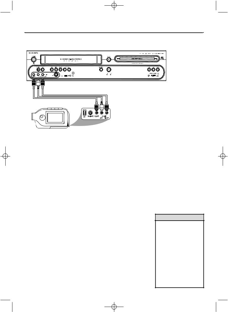
Connecting to Other Equipment for Dubbing
You can connect a VCR, Camcorder, or DVD Player to the COMPONENT VIDEO IN (Y PB PR), S-VIDEO IN, VIDEO IN, and AUDIO IN jacks on the rear panel or to the VIDEO IN,AUDIO IN, or SV (S-Video) IN jacks on the front panel.
A sample connection with a Camcorder is shown here, using the AUDIO/VIDEO IN jacks on the front of the Recorder. These jacks are the most easily accessible. Other equipment will connect similarly, but this is a common connection possibility.
Use the IN jacks on the rear of the Recorder for permanent connections.That will hide the cables from view.
1 Connect the Recorder directly to your TV.
Choose a connection from pages 10-16.
2 To access the AUDIO/VIDEO IN jacks on the front of the Recorder, flip down the door that covers the jacks.
3 Connect a video cable to the VIDEO OUT jack of your Camcorder and to the yellow VIDEO IN jack on the front of the Recorder. Use an RCA-style video cable, which is usually marked with yellow. (One video cable is supplied with the Recorder.)
4 Connect audio cables to the AUDIO OUT jacks of your Camcorder and to the red and white AUDIO IN jacks on the front of the Recorder. One set of audio cables is supplied with the Recorder. Most audio cables are red and white. Match the cable colors to the jack colors.
5 When all connections are complete, connect all the equipment to power. Turn on all the equipment. Press STANDBY-ON y on the front of the Recorder to turn it on.
6 Set your TV to the correct Video In channel. This will be channel 3 or 4 or a specific Video In channel, depending on your connection between the Recorder and the TV. Refer to the connection details on pages 10-16. Or, simply go to channel 5 on your TV, then change channels down until you see the Recorder’s logo on the TV screen. The Initial Setup screen will appear the first time you turn on the Recorder. Go to page 18 to continue.
7 To watch or record the material playing on the other equipment, press MONITOR to put the Recorder in Monitor mode. Press K or L to select CAM1 at the Recorder. This is located after your highest TV channel and before your lowest TV channel. Choose CAM1 if you used the connection shown on this page (with the jacks on the front of the Recorder). If you use the EXT 1 or EXT 2 jacks on the rear of the Recorder instead, choose channel EXT 1 or EXT 2. Choose the channel that matches the jacks to which you connected the other equipment.
Start playing the material by pressing PLAY on the other equipment. Press RECORD I on the front of the Recorder to start recording on a DVD+R/DVD+RW or a videotape. (See page 44 for DVD+R or DVD+RW recording.)
Helpful Hints
•Most prerecorded videotapes and DVDs are copy protected. If you try to copy them, the Recorder display may show “COPY PROTECT.”
•If the Recorder’s display shows “NO SIGNAL,” adjust the tracking or play the videotape on the VCR/Camcorder/External VCR.
See your VCR/Camcorder manual to improve the quality of tape play.
•Do not connect a Progressive Scan video source (such as a DVD Player) to the EXT 1 COMPONENT VIDEO IN jacks. The Recorder cannot receive Progressive Scan video.
E9490UD_EN.qx3 04.8.3 11:55 AM Page 18
18 Initial Setup
Initial Setup screens will appear the very first time you turn on the Recorder. These on-screen messages and menus will help you set up Recorder features quickly, including TV channels and language options.
During Initial Setup,“IS TV ON? CO3” will appear on the Recorder’s display panel.The Initial Setup information shows on your TV.
“IS TV ON? CO3” indicates you should turn on your television and set it to channel 3 or the correct Video In channel. Even though your TV may be on, you must set it to the correct Video In channel to see the Initial Setup messages. See pages 9-16 to determine the correct Video In channel for your connection. Or, check your TV owner’s manual for details.
Follow the steps below to set up the Recorder. You cannot turn off the
Recorder until you finish the Initial Setup.The only way to quit the Initial Setup is to disconnect the power cord. If you quit, the Initial Setup screens will appear again the next time you turn on the Recorder.The screens will not go away until you finish the Initial Setup. Also, you cannot open the Disc tray while “IS TV ON? CO3” appears. (“INSTALL RECORDER FIRST” will show on the display panel.)
If the setup screens do not appear, your Recorder has been set up previously. You can change setup items later. See the pages listed at each step below for each feature.
1 Press STANDBY-ONy to turn on the Recorder.
|
The Menu Language screen will appear first. Press K or L to choose |
||||
|
English, Espanol, or Francais, then press the OK button. |
||||
2 The Recorder’s menus, displays, and messages will be in the language |
|||||
|
you selected. |
|
|
|
|
|
To change the Recorder’s Menu Language later, see page 66. |
||||
|
|
|
|||
|
~ |
Initial Setup |
|
||
|
Menu Language |
|
|
|
|
|
|
English |
K |
|
|
|
|
L |
|
|
|
|
|
|
|
|
|
|
|
Español |
|
|
|
|
|
Français |
|
|
|
|
|
|
|
|
|
|
Press OK to continue |
|
|
|
|
|
|
|
|
|
|
3 The Audio Language menu appears next. Press K or L to choose the language you prefer, then press OK.
The Recorder will play Discs in this language if it is on the Disc.The DVD Disc menu will appear in the same language if available.
Some Discs require you to choose the audio language or the Disc Menu language from the Disc menu.The Disc preferences or defaults may override your selection in the Recorder’s Audio Language menu.
To change the Audio Language later (as Playback Audio), see pages 37 and 66.
~Initial Setup
Audio Language
English K
L
Español
Français
Português
Italiano
Press OK to continue
Instructions continue on the next page.


 1
1
 2-3
2-3
Helpful Hint
•The Recorder’s features will scroll across the display panel when you first connect the power cord.This is a demonstration that cannot be cancelled. It will not appear anymore after you set up the Recorder.
E9490UD_EN.qx3 04.8.3 11:55 AM Page 19
Initial Setup (cont’d) 19
Continued from previous page
4 The Subtitle Language menu appears next. Press K or L to choose the language you prefer for subtitles, then press OK.
The Recorder will show subtitles in this language if they are available. If the language is not available, either there will be no subtitles or subtitles will be in the default language of the Disc.
Some DVDs require you to choose a subtitle language from the Disc menu. Disc preferences or defaults may override your selection in the Recorder’s Subtitle Language menu.
To change the Subtitle Language later, see pages 37 and 66.
~ |
Initial Setup |
|
Subtitle Language |
|
|
English |
K |
|
L |
||
|
||
Español |
|
|
Français |
|
|
Português |
|
|
Italiano |
|
|
Press OK to continue |
|
|
The TV Shape menu appears next. Press K or L to choose the |
||||
|
preferred TV Shape, then press OK. |
||||
5 To change the TV Shape later or for details on TV Shapes, see page 63. |
|||||
|
~ |
Initial Setup |
|
||
|
TV Shape |
|
|
|
|
|
|
4:3 letterbox |
K |
|
|
|
|
L |
|
|
|
|
|
4:3 panscan |
|
|
|
|
|
16:9 |
|
|
|
|
|
|
|
|
|
|
Press OK to continue |
|
|
|
|
|
|
|
|
|
|
6 “If you have connected the antenna - press OK” appears next. If you have connected an Antenna or Cable TV signal to the Recorder’s ANTENNA IN jack, press OK.
If you have not connected the Antenna or Cable TV signal, take a moment now to do so. After the Antenna/Cable TV signal is connected, press OK. See pages 10-16.
To reset TV channels later, or to add/delete new channel choices later, see page 28.
7 “Searching for TV channels” will appear, along with a scale showing channels are being memorized.The number of channels found will show on the screen as the searching progresses.This will take a few minutes, depending on the number of channels available in your area.
When the channel search finishes,“Auto ch. search complete” will appear, along with the total number of channels found.
Installation
Auto Ch. Programming
Auto ch. search complete
024 Channels found
To exit press
SYSTEM MENU
8 Press SYSTEM MENU. The Recorder automatically turns off, then turns on again.You will see a DVD background screen and some Information Boxes. See page 35.
The Recorder is ready for use!


 8
8  4-6
4-6

E9490UD_EN.qx3 04.8.3 11:55 AM Page 20
20 Quick Videotape Playback
Read and follow the steps below to play a videotape.
1 Turn on the TV. Set it to channel 3 or 4 or its AUDIO/VIDEO IN channel. This depends on how you connected the Recorder to a TV. See pages 10-14.
2 With the Recorder power off, insert a videotape in the cassette compartment of the Recorder. The VCR light will appear on the front of the Recorder.
If the power is already on, press VCR to put the Recorder in VCR mode.The VCR light will appear on the front of the Recorder.
3 Press PLAY B.
4 Press STOP C to stop playback.
5 Press PREV/REW H to rewind the videotape.
6 After the videotape stops, press OPEN/CLOSE/EJECT A to remove the videotape.
1 Turn on the TV.
Insert a videotape in the 2 cassette compartment.
6 |
|
5 |
3 |
|
4 |
Helpful Hint
•You must connect the Recorder to a TV using the RF coaxial cable or composite video in order to use the VCR features. These hookups are explained on pages 10 and 14.
E9490UD_EN.qx3 04.8.3 11:55 AM Page 21
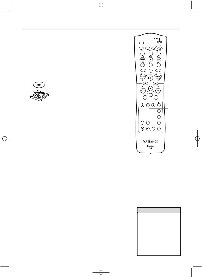
Quick Disc Playback 21
1
2 Press the DVD button on the remote control so the DVD light appears on the front of the Recorder. You should see the DVD background picture on the TV screen (if no Disc is in the Recorder).
3 Press OPEN/CLOSE/EJECT A to open the disc tray.
Load your Disc in the tray, with the label facing up and the shiny side facing down. If the Disc (DVD) is two-sided, make sure the label of the side you want to play is facing up.
LABEL
|
Press OPEN/CLOSE/EJECT A again to close the tray. |
|||
|
“Reading” will show on the display panel.The Recorder may read a |
|||
4 Disc for several seconds. |
|
|
||
5 |
Press PLAY B to start playback. |
|
||
• If you are playing a DVD, a Disc menu may appear. If the Title or |
||||
Chapter selections are numbered, press a Number button to select |
||||
|
an item. Or, press K, L, s, or B to select an item, then press OK. |
|||
|
Continue until you start playing the Disc. Or, follow the instruc- |
|||
|
tions in the DVD Disc menu. |
|
|
|
|
• If you are playing a DVD+RW/DVD+R, the Index Picture Screen |
|||
|
will appear. See page 34. Press K or L to select the Title you want |
|||
|
to play, then press OK. If the Disc is blank, the display will show |
|||
|
“EMPTY DISC.” |
|
|
|
|
To stop play at any time, press STOP C. |
|
||
|
If Auto resume is On, DVD play will resume at the same point the |
|||
6 next time you play the DVD.To play the DVD from its beginning, |
||||
|
restart play from the DVD’s Disc menu. |
|
||
|
If Auto resume is Off, Resume |
will appear in the top left cor- |
||
|
ner when you play the DVD later.While Resume |
appears, |
||
|
press PLAY B to resume play from the point at which you last |
|||
|
stopped it. Otherwise, play will start at the beginning of the DVD. |
|||
|
Resume |
will disappear after about 15 seconds. |
|
|
|
Auto resume is On when you purchase the Recorder. However, you |
|||
|
can turn it On or Off. See page 56. |
|
|
|
3-4


 1
1
5 |
|
6 |
2 |
Helpful Hints
•If the Disc is Locked by Access Control, you must enter the fourdigit code or unlock the Disc. See pages 57-61.
•DVDs have a region code.Your Recorder will not play Discs that have a region code other than 1 (one)or ALL. See page seven.
•Auto resume does not affect Audio CDs. If you restart play of an Audio CD, play starts at the beginning of the Audio CD.
E9490UD_EN.qx3 04.8.3 11:55 AM Page 22
22 Quick Disc Recording
The Recorder can record TV programming onto a DVD+RW or DVD+R. Before you begin, set up TV channels. See pages 18-19 and 28. Use an unprotected, unfinalized, recordable DVD+RW/DVD+R.
1 Press DVD so the DVD light appears on the front of the Recorder.
2 Press OPEN/CLOSE/EJECT A to open the disc tray.
3 Insert a recordable DVD+RW/DVD+R with the label facing up.
Press OPEN/CLOSE/EJECT A to close the disc tray.The Index Picture Screen will appear. See page 34. If the Disc is empty and has no recordings,“EMPTY DISC” will appear on the display panel.
LABEL
Press L to select an empty Title box on a DVD+RW. To avoid |
|
4 Titleoverwritingbox. |
previous recordings on a DVD+RW, choose the last Empty |
On a DVD+R, the Recorder automatically starts recording at the end of the Disc, so you do not need to select an Empty Title box.You cannot overwrite recordings on a DVD+R.
5 Press MONITOR to see TV channels through the Recorder.
6 Press CHANNEL +/- or the Number buttons to select the channel you wish to record.
To record material playing on equipment you connected to the Recorder, select EXT1, EXT2 or CAM1. Choose the EXT (External) or CAM (Camcorder) channel that matches the jack to which you connected the other equipment. See page 17.
If you are using a Cable Box/Satellite Receiver, set the Recorder to channel 3 or 4 (or the EXT or CAM channel). (Choose the output channel of your Cable Box/Satellite Receiver or the jacks to which you connected the Cable Box/Satellite Receiver.) Then, change TV channels at the Cable Box/Satellite Receiver. See page 11.
7 Press DVD REC I to record the selected channel. Recording will begin after a few seconds. (The Disc has to prepare for recording.) To pause recording, press PAUSE once on the remote.
To resume recording, press DVD REC I again.
8 Press STOP C to stop recording.The Index Picture Screen will reappear after a few seconds. On a brief recording on a new DVD+RW, formatting the Disc will take a minute.
If you plan to play a DVD+R on another DVD Player, finalize the Disc. Follow the steps on page 55.You cannot record or edit a DVD+R after you finalize it. To edit your recordings, see page 54. However, editing changes may not be accessible when you play the Disc on other DVD Players.
2-3


8


 1
1
4


 7
7


 6 5
6 5


Helpful Hints
•You cannot record only Audio (sound) to a DVD+RW/DVD+R. You must record both audio and video (sound and picture).
•To erase a recording, see “Erase this title” details on page 50.
•You cannot duplicate copyrighted DVDs, videotapes, or TV broadcasts using the Recorder. “COPY PROTECT” may appear on the display panel if you attempt this.
E9490UD_EN.qx3 04.8.3 11:55 AM Page 23
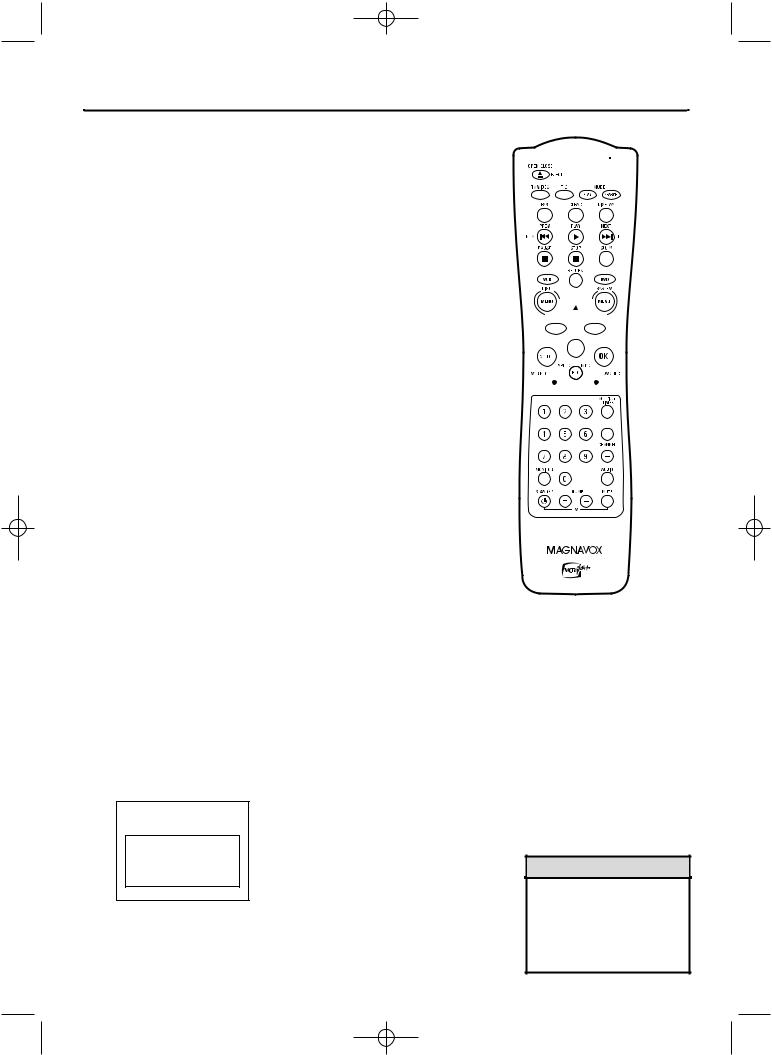
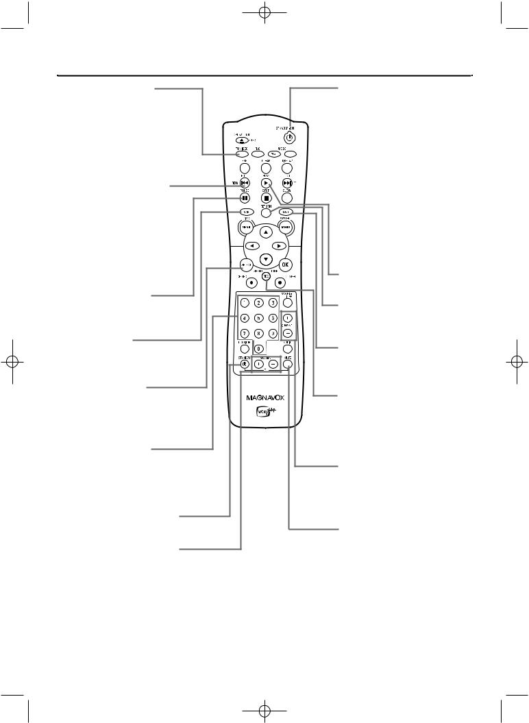
Remote Control 23
TV/VIDEO Button
Press to switch between TV and Video positions. In Video position, watch a Disc/videotape or watch/record TV programs (changing channels at the Recorder).
Use TV position to watch TV channels (changing channels at the TV) or watch one program while recording another.
PREV/REW H Button
In DVD mode, press to return to the beginning of the cur-
rent Chapter/Track. Press repeatedly to return to previous Chapters/Tracks. Press and hold for two seconds to
search backward during play. In VCR mode, press to search
a videotape.
See pages 75 and 76.
PAUSE k Button
Press to pause Disc or videotape play or recording (except OTR).
VCR Button
Press to activate the remote control in VCR mode.
Press to select the VCR output mode.
SELECT Button
In DVD mode, press to adjust timer recording settings. See page 45.
Press to choose Interlaced or Progressive Scan. See page 63.
Number Buttons
Use to select TV channels. If you have Cable TV, channels 1-125 are available. If you have an antenna, channels 2-69 are available. In DVD mode, press to select a Track or Chapter for playback.
TV STANDBY y Button
Press to turn on or off the power of some Magnavox TVs.
TV VOLUME +/– Buttons
Press to adjust the volume of some Magnavox TVs.
The TV VOLUME +/– buttons do not work with all TVs.
STANDBY-ON y Button
Press to turn on or off the power of the Recorder.


 SEARCH MODE Button
In VCR mode, press for a Time Search or an Index Search. See
page 75.
 NEXT/FF G Button
In DVD mode, press to skip
to the next Chapter or Track during play. Press and hold for two seconds to search forward during play.
In VCR mode, press to search a videotape. See pages 75-76.
PLAY B Button
Press to begin Disc or videotape playback.
RETURN Button
Press to go to a previous menu on a Video CD or some DVDs.
DVD Button
Press to activate the remote control in DVD mode.
Press to select the DVD output mode.
REC SPEED/MODE Button
Press to select a Disc or videotape recording speed.
See pages 52 and 69.
This determines the quality of the recording and the length of time you can record.
CHANNEL +/- Buttons
Press to change TV channels at the Recorder in Monitor or VCR mode.
Press to adjust videotape tracking during. See page 77.
TV MUTE Button
Press to mute the sound on some Magnavox TVs.
The TV MUTE button does not work with all TVs.

E9490UD_EN.qx3 04.8.3 11:55 AM Page 24
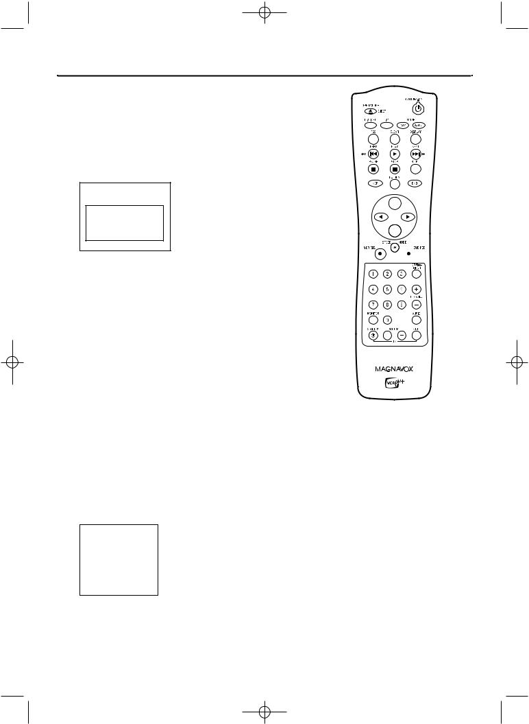
24 Remote Control (cont’d)
OPEN/CLOSE/EJECT A
Button
Press to open or close the Disc tray in DVD mode. Press to eject a videotape in VCR mode.
T/C Button (Title/Chapter)
Press to select “T” (Title/Track) or “C” (Chapter) in the Menu Bar.Then press op to select the Title/Track/Chapter you want to play.
This button has no effect during Monitor mode.
FSS Button
(Favorite Scene Selection)
Press to display or remove the Favorite Scene Selection menu during playback of a DVD+R or DVD+RW. See page 54.
STOP C Button
Press to stop playback or recording.
DISC MENU Button
Press to access or remove a DVD
Disc menu in DVD mode.
opsB Buttons
Press to select menu items.
VCR REC I Button
Press to begin VCR recording.
See page 69.
Press repeatedly to start a One-Touch Recording on a videotape. See page 71.
MONITOR Button
Press to choose Disc mode or Monitor mode. In Disc mode, use the Index Picture Screen or view Disc playback. In Monitor mode, watch TV channels through the Recorder or make a Disc recording. See page 22.
Helpful Hints
•When VCR REC I is pressed in DVD mode, the Recorder switches to VCR mode and starts recording on the videotape.
•When DVD REC I is pressed in VCR mode, the Recorder switches to DVD mode and starts recording on the DVD+R/DVD+RW.
PLAY MODE Button
Press during Disc play to choose a Repeat, Shuffle, or Scan mode.
CLEAR Button
In DVD mode, press to delete the last entry of information into a menu. Press to clear a timer recording. See page 47. In VCR mode, press to reset the videotape counter. See page 74.
DISPLAY Button
In VCR mode, press to see status displays. See page 68.
SLOW Button
Press to view a videotape in slow motion. See page 76.
SYSTEM MENU Button
Press to access or remove the Recorder’s Setup menu.This also puts the Recorder in DVD mode automatically.
OK Button
Press to acknowledge or approve a menu selection.
DVD REC I Button
Press to start a Disc recording. Press repeatedly to start a One-Touch Recording on a DVD+R or DVD+RW.
VCR Plus+/TIMER button
Press to set a timer recording with the VCR Plus+ programming system.
See page 46.
Press to access or remove the Timer Recording menu in DVD mode. See pages 45-47.
AUDIO Button
In DVD mode, press to select a different audio language during DVD play. Multiple languages must be available on the DVD.
See page 37.
In VCR mode, press to select HIFI or MONO. See page 76.

E9490UD_EN.qx3 04.8.3 11:55 AM Page 25
Cassette Compartment
Insert a video cassette here.
VCR Display Panel
Messages about current VCR operations appear here.
See Display Messages below.
Display Panel (VCR) 25
VCR light (Orange)
This light appears when the Recorder is in VCR mode.You can only watch videotapes when the VCR light is on.
Appears during recording; flashes when recording is paused
Indicates a videotape is in the Recorder
Appears if videotape play is paused or during slow motion videotape play
Appears during videotape play
Indicates the selected tape speed
Appears during DVD to VCR or VCR to DVD duplication
Indicates the elapsed playing time of a videotape; also displays the remaining time for an OTR

E9490UD_EN.qx3 04.8.3 11:55 AM Page 26
26 Front Panel
|
|
|
|
|
|
|
|
|
|
|
|
|
STANDBY-ON y Button |
|
|
|
|
|
|
|
|
|
|
DVD OPEN/CLOSE A Button |
|||||||||||||||||||||||||
|
|
|
|
|
|
|
|
|
|
|
|
|
|
|
|
|
|
|
|
|
|
||||||||||||||||||||||||||||
|
|
|
|
|
|
|
|
|
|
|
|
|
Press to turn the power on or off. |
|
|
|
|
|
|
|
|
|
Press to open or close the Disc Tray. |
||||||||||||||||||||||||||
|
|
|
|
|
|
|
|
|
|
|
|
|
POWER ON Light |
|
|
|
|
|
|
|
|
|
SOURCE Button |
||||||||||||||||||||||||||
|
|
|
|
|
|
|
|
|
|
|
|
|
Appears when the power is on. |
|
|
|
|
|
|
|
|
|
Press to select DVD mode or VCR |
||||||||||||||||||||||||||
|
|
|
|
|
|
|
|
|
|
|
|
|
STOP C / EJECT A Button (VCR) |
|
|
|
|
|
|
|
|
|
mode.The DVD light appears in DVD |
||||||||||||||||||||||||||
|
|
|
|
|
|
|
|
|
|
|
|
|
|
|
|
|
|
|
|
|
|
mode.The VCR light appears in VCR |
|||||||||||||||||||||||||||
|
|
|
|
|
|
|
|
|
|
|
|
|
|
|
|
|
|
||||||||||||||||||||||||||||||||
|
|
|
|
|
|
|
|
|
|
|
|
|
Press once to stop videotape playback.When |
|
|
|
|
|
|
|
|
|
mode. |
||||||||||||||||||||||||||
|
|
|
|
|
|
|
|
|
|
|
|
|
play is stopped, press to eject the videotape. |
|
|
|
|
|
|
|
|
|
DVD Light |
||||||||||||||||||||||||||
|
|
|
|
|
|
|
|
|
|
|
|
|
PLAY B Button (VCR) |
|
|
|
|
|
|
|
|
|
|||||||||||||||||||||||||||
|
|
|
|
|
|
|
|
|
|
|
|
|
|
|
|
|
|
|
|
||||||||||||||||||||||||||||||
|
|
|
|
|
|
|
|
|
|
|
|
|
|
|
|
|
|
|
|
|
|
This light appears when the Recorder is |
|||||||||||||||||||||||||||
|
|
|
|
|
|
|
|
|
|
|
|
|
|
|
|
|
|
||||||||||||||||||||||||||||||||
|
|
|
|
|
|
|
|
|
|
|
|
|
Press to play a videotape. |
|
|
|
|
|
|
|
|
|
in DVD mode. |
||||||||||||||||||||||||||
|
|
|
|
|
|
|
|
|
|
|
|
|
Press to release Slow, Search, or Still mode and |
|
|
|
|
|
|
|
|
|
|
|
|
|
|
|
|
|
|
|
|
|
|
||||||||||||||
|
|
|
|
|
|
|
|
|
|
|
|
|
return to playback. See page 76. |
|
|
|
|
|
|
|
|
|
|
|
|
|
|
|
|
|
|
|
|
|
|
||||||||||||||
|
|
|
|
|
|
|
|
|
|
|
|
|
|
|
|
|
|
|
REW E Button (VCR) |
|
|
|
|
|
|
RECORD I Button (DVD) |
|
|
|||||||||||||||||||||
|
|
|
|
|
|
|
|
|
|
|
|
|
|
|
|
|
|
|
|
|
|
|
|
|
|
||||||||||||||||||||||||
|
|
|
|
|
|
|
|
|
|
|
|
|
|
|
|
|
|
|
Press to rewind a videotape. See page 76. |
|
|
|
|
|
|
Press to start a Disc recording. |
|
||||||||||||||||||||||
|
|
|
|
|
|
|
|
|
|
|
|
|
|
|
|
|
|
|
F.FWD D Button (VCR) |
|
|
|
|
|
|
See page 22. |
|
||||||||||||||||||||||
|
|
|
|
|
|
|
|
|
|
|
|
|
|
|
|
|
|
|
|
|
|
|
|
|
PLAY B Button (DVD) |
|
|
|
|
|
|
|
|
|
|
||||||||||||||
|
|
|
|
|
|
|
|
|
|
|
|
|
|
|
|
|
|
|
|
|
|
|
|
|
|
|
|
|
|
|
|
|
|
|
|||||||||||||||
|
|
|
|
|
|
|
|
|
|
|
|
|
|
|
|
|
|
|
Press to fast forward a videotape. |
|
|
|
|
|
|
|
|
|
|
|
|||||||||||||||||||
|
|
|
|
|
|
|
|
|
|
|
|
|
|
|
|
|
|
|
|
|
|
|
|
|
|
|
|
|
|
|
|||||||||||||||||||
|
|
|
|
|
|
|
|
|
|
|
|
|
|
|
|
|
|
|
See page 76. |
|
|
|
|
|
|
Press to start Disc playback. |
|
|
|||||||||||||||||||||
|
|
|
|
|
|
|
|
|
|
|
|
|
|
|
|
|
|
|
RECORD I Button (VCR) |
|
|
|
|
|
|
See page 21. |
|
|
|||||||||||||||||||||
|
|
|
|
|
|
|
|
|
|
|
|
|
|
|
|
|
|
|
|
|
|
|
|
|
STOP C Button (DVD) |
|
|
|
|
|
|
|
|
|
|||||||||||||||
|
|
|
|
|
|
|
|
|
|
|
|
|
|
|
|
|
|
|
|
|
|
|
|
|
|
|
|
|
|
|
|
|
|
||||||||||||||||
|
|
|
|
|
|
|
|
|
|
|
|
|
|
|
|
|
|
|
Press to start a videotape recording. See |
|
|
|
|
|
|
|
|
|
|
|
|||||||||||||||||||
|
|
|
|
|
|
|
|
|
|
|
|
|
|
|
|
|
|
|
|
|
|
|
|
|
|
|
|
|
|
|
|
||||||||||||||||||
|
|
|
|
|
|
|
|
|
|
|
|
|
|
|
|
|
|
|
page 69. |
|
|
|
|
|
|
Press to stop Disc playback. |
|
|
|
|
|||||||||||||||||||
|
|
|
|
|
|
|
|
|
|
|
|
|
|
|
|
|
|
|
Press repeatedly to start a One-Touch |
|
|
|
|
|
|
See page 21. |
|
|
|
|
|||||||||||||||||||
|
|
|
|
|
|
|
|
|
|
|
|
|
|
|
|
|
|
|
Recording. See page 71. |
|
|
|
|
|
|
DVD Display Panel |
|
|
|
|
|
|
|
||||||||||||||||
|
|
|
|
|
|
|
|
|
|
|
|
|
|
|
|
|
|
|
|
|
|
|
|
|
|
|
|
|
|
|
|
|
|
|
|
|
|
||||||||||||
|
|
|
|
|
|
|
|
|
|
|
|
|
|
|
|
|
|
|
|
|
|
|
|
|
|
|
|
|
|
|
|
|
|
|
|
|
|
|
|
|
|||||||||
|
|
|
|
|
|
|
|
|
|
|
|
|
|
|
|
|
|
|
|
|
CHANNEL K L Buttons |
|
|
|
|
|
|
Shows Disc status in DVD |
|
|
|
|
|||||||||||||||||
|
|
|
|
|
|
|
|
|
|
|
|
|
|
|
|
|
|
|
|
|
|
|
|
|
|
|
mode. |
|
|
|
|
|
|
|
|
|
|
|
|||||||||||
|
|
|
|
|
|
|
|
|
|
|
|
|
|
|
|
|
|
|
|
|
|
|
|
|
|
|
|
|
|
|
|
|
|
|
|
|
|||||||||||||
|
|
|
|
|
|
|
|
|
|
|
|
|
|
|
|
|
|
|
|
|
Press to select TV channels. |
|
|
|
|
|
|
|
|
|
|
|
|
|
|
|
|
|
|
|
|
|
|
||||||
|
|
|
|
|
|
|
|
|
|
|
|
|
|
|
|
|
|
|
|
|
|
|
|
|
|
|
|
|
|
|
|
|
|
|
|
|
|
|
|
|
|
|
|
|
|
|
|
|
|
|
|
|
|
|
|
|
|
|
|
|
|
|
|
|
|
|
|
|
|
|
|
|
|
|
|
|
|
|
|
|
|
|
|
|
|
|
|
|
|
|
|
|
|
|
|
|
|
|
|
|
|
|
|
|
|
|
|
|
|
|
|
|
|
|
|
|
|
|
|
|
|
|
|
|
|
|
|
|
|
|
|
|
|
|
|
|
|
|
|
|
|
|
|
|
|
|
|
|
|
|
|
|
|
|
|
|
|
|
|
|
|
|
|
|
|
|
|
|
|
|
|
|
|
|
|
|
|
|
|
|
|
|
|
|
|
|
|
|
|
|
|
|
|
|
|
|
|
|
|
|
|
|
|
|
|
|
|
|
|
|
|
|
|
|
|
|
|
|
|
|
|
|
|
|
|
|
|
|
|
|
|
|
|
|
|
|
|
|
|
|
|
|
|
|
|
|
|
|
|
|
|
|
|
|
|
|
|
|
|
|
|
|
|
|
|
|
|
|
|
|
|
|
|
|
|
|
|
|
|
|
|
|
|
|
|
|
|
|
|
|
|
|
|
|
|
|
|
|
|
|
|
|
|
|
|
|
|
|
|
|
|
|
|
|
|
|
|
|
|
|
|
|
|
|
|
|
|
|
|
|
|
|
|
|
|
|
|
|
|
|
|
|
|
|
|
|
|
|
|
|
|
|
|
|
|
|
|
|
|
|
|
|
|
|
|
|
|
|
|
|
|
|
|
|
|
|
|
|
|
|
|
|
|
|
|
|
|
|
|
|
|
|
|
|
|
|
|
|
|
|
|
|
|
|
|
|
|
|
|
|
|
|
|
|
|
|
|
|
|
|
|
|
|
|
|
|
|
|
|
|
|
|
|
|
|
|
|
|
|
|
|
|
|
|
|
|
|
|
|
|
|
|
|
|
|
|
|
|
|
|
|
|
|
|
|
|
|
|
|
|
|
|
|
|
|
|
|
|
|
|
|
|
|
|
|
|
|
|
|
|
|
|
|
|
|
|
|
|
|
|
|
|
|
|
|
|
|
|
|
|
|
|
|
|
|
|
|
|
|
|
|
|
|
|
|
|
|
|
|
|
|
|
|
|
|
|
|
|
|
|
|
|
|
|
|
|
|
|
|
VCR Light
This light appears when the Recorder is in VCR mode.
D.DUBBING Button
Press to start DVD to VCR or VCR to
DVD duplication. See pages 44 and 73.
IR (infrared) Remote Sensor
Receives a signal from your Recorder’s remote control so you can work your Recorder from a distance.
Point the remote here, not at your TV.
SV (S-Video),VIDEO and AUDIO In jacks
Use these jacks when connecting a Camcorder or other equipment to the Recorder. See page 17. When recording material that is playing on the other equipment, set the Recorder to CAM1 in monitor mode.
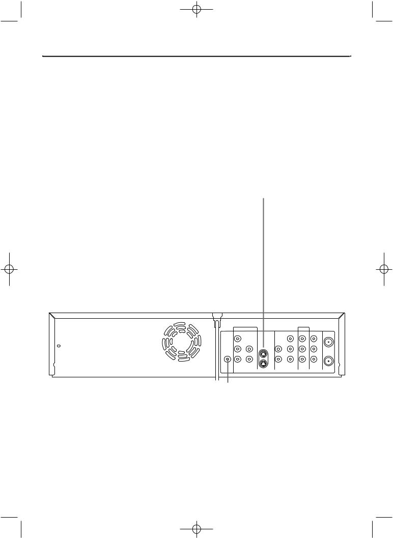
E9490UD_EN.qx3 04.8.3 11:55 AM Page 27
Rear Panel 27
ANTENNA IN jack |
|
|
|
|
|
|
|
|
|
|
|
|
|
|
|
|
|
|
|
|
|
|
|
|
|
|
|
|
|
|
|
||||||||
Connect your antenna or Cable TV signal here. See pages 10-16. |
|
|
|
|
|
|
|
|
|
|
|
|
|
|
|
|
|
|
|
|
|
||||||||||||||||||
VIDEO OUT jack (yellow) |
|
|
|
|
|
|
|
|
|
|
|
|
|
|
|
|
|
|
|
|
|
|
|
|
|
|
|
|
|||||||||||
Connect the yellow video cable (supplied) here and to the TV’s |
|
|
|
|
|
|
|
|
|
|
|
|
|
|
|
|
|
|
|
|
|
||||||||||||||||||
Video In jack.This supplies the picture for both VCR and DVD |
|
|
|
|
|
|
|
|
|
|
|
|
|
|
|
|
|
|
|
|
|
||||||||||||||||||
modes. See page 14. |
|
|
|
|
|
|
|
|
|
|
|
|
|
|
|
|
|
|
|
|
|
||||||||||||||||||
EXT2 Jacks |
|
|
|
|
|
|
|
|
|
|
|
|
|
|
|
|
|
|
|
|
|
|
|
|
|
|
|
|
|
|
|
|
|
||||||
VIDEO IN jack (yellow) |
|
|
|
|
|
|
|
|
|
|
|
|
|
|
|
|
|
|
|
|
|
||||||||||||||||||
Connect a video cable from an optional Camcorder,VCR, or DVD |
|
|
|
|
|
|
|
|
|
|
|
|
|
|
|
|
|
|
|
|
|
||||||||||||||||||
Player here. See page 17. |
|
|
|
|
|
|
|
|
|
|
|
|
|
|
|
|
|
|
|
|
|
||||||||||||||||||
AUDIO IN Jacks / Left (white) and Right (red) |
|
|
|
|
|
|
|
|
|
|
|
|
|
|
|
|
|
|
|
|
|
||||||||||||||||||
Connect audio cables coming from the audio out jacks of a cam- |
|
|
|
|
|
|
|
|
|
|
|
|
|
|
|
|
|
|
|
|
|
||||||||||||||||||
corder, another VCR, another DVD Player, or Stereo here. See |
|
|
|
|
|
|
|
|
|
|
|
|
|
|
|
|
|
|
|
|
|
||||||||||||||||||
page 17. This will be useful if you want to copy a videotape or |
|
|
|
|
|
|
|
|
|
|
|
|
|
|
|
|
|
|
|
|
|
||||||||||||||||||
watch material that is playing on other equipment. |
|
|
|
|
|
|
|
|
|
|
|
|
|
|
|
|
|
|
|
|
|
||||||||||||||||||
COMPONENT VIDEO OUT (Y PB PR) jacks (red, green, blue) |
|
|
|
|
|
|
|
|
|
|
|
|
|
|
|
|
|
|
|
|
|
|
|||||||||||||||||
Connect component video cables (not supplied) here and to the |
|
|
|
|
|
|
|
|
|
|
|
|
|
|
|
|
|
|
|
|
|
||||||||||||||||||
Component Video In jacks of a TV. See page 12. |
|
|
|
|
|
|
|
|
|
|
|
|
|
|
|
|
|
|
|
|
|
||||||||||||||||||
EXT2 S-VIDEO IN jack |
|
|
|
|
|
|
|
|
|
|
|
|
|
|
|
|
|
|
|
|
|
|
|
|
|
|
|
|
|||||||||||
|
|
|
|
|
|
|
|
|
|
|
|
|
|
|
|
|
|
|
|
|
|
|
|
|
|
|
|
||||||||||||
Use an S-video cable (not supplied) to connect this jack to the |
|
|
|
|
|
|
|
|
|
|
|
|
|
|
|
|
|
|
|
|
|
||||||||||||||||||
S-Video Out jack of optional additional equipment. See page 17. |
|
|
|
|
|
|
|
|
|
|
|
|
|
|
|
|
|
|
|
|
|
||||||||||||||||||
EXT2 S-VIDEO OUT jack |
|
|
|
|
|
|
|
|
|
|
|
|
|
|
|
|
|
|
|
|
|
|
|
|
|
|
|
|
|||||||||||
|
|
|
|
|
|
|
|
|
|
|
|
|
|
|
|
|
|
|
|
|
|
|
|
|
|
|
|
||||||||||||
Connect an S-Video cable here and to a TV’s S-Video In jack. See |
|
|
|
|
|
|
|
|
|
|
|
|
|
|
|
|
|
|
|
|
|
||||||||||||||||||
page 13. |
|
|
|
|
|
|
|
|
|
|
|
|
|
|
|
|
|
|
|
|
|
||||||||||||||||||
EXT1 jacks |
|
|
|
|
|
|
|
|
|
|
|
|
|
|
|
|
|
|
|
|
|
|
|
|
|
|
|
|
|
|
|
|
|
||||||
|
|
|
|
|
|
|
|
|
|
|
|
|
|
|
|
|
|
|
|
|
|
|
|
|
|
|
|
|
|
|
|
|
|||||||
AUDIO IN jacks / Left (white) and Right (red) |
|
|
|
|
|
|
|
|
|
|
|
|
|
|
|
|
|
|
|
|
|
||||||||||||||||||
Connect audio cables here and to the AUDIO OUT jacks of other |
|
|
|
|
|
|
|
|
|
|
|
|
|
|
|
|
|
|
|
|
|
||||||||||||||||||
equipment. See page 17. |
|
|
|
|
|
|
|
|
|
|
|
|
|
|
|
|
|
|
|
|
|
||||||||||||||||||
COMPONENT VIDEO IN (Y PB PR) jacks (red, green, blue) |
|
|
|
|
|
|
|
|
|
|
|
|
|
|
|
|
|
|
|
|
|
||||||||||||||||||
Connect these jacks to the Component Video Out jacks of option- |
|
|
|
|
|
|
|
|
|
|
|
|
|
|
|
|
|
|
|
|
|
||||||||||||||||||
al video equipment (for example, a DVD Player). See page 17. |
|
|
|
|
|
|
|
|
|
|
|
|
|
|
|
|
|
|
|
|
|
||||||||||||||||||
AC Power Cord |
|
|
|
|
|
|
|
|
|
|
|
|
|
|
|
|
|
|
|
|
|
|
|
|
|
|
|
|
|
|
|
|
|
|
|||||
|
|
|
|
|
|
|
|
|
|
|
|
|
|
|
|
|
|
|
|
|
|
|
|
|
|
|
|
|
|
||||||||||
Connect to a standard AC outlet to supply power to the Recorder. |
|
|
|
|
|
|
|
|
|
|
|
|
|
|
|
|
|
|
|
|
|
|
|
|
|
||||||||||||||
|
|
|
|
|
|
|
|
|
|
|
|
|
|
|
|
|
|
|
|
|
|
|
|
|
|
|
|
|
|
|
|
|
|
|
|
|
|
|
|
|
|
|
|
|
|
|
|
|
|
|
|
|
|
|
|
|
|
|
|
|
|
|
|
|
|
|
|
|
|
|
|
|
|
|
|
|
|
|
|
|
|
|
|
|
|
|
|
|
|
|
|
|
|
|
|
|
|
|
|
|
|
|
|
|
|
|
|
|
|
|
|
|
|
|
|
|
|
||
|
|
|
|
|
|
|
|
|
|
|
|
|
|
|
|
|
|
EXT1 |
|
|
|
|
|
|
|
|
|
|
|
|
|
EXT2 |
|
|
|
||||
|
|
|
|
|
|
|
|
|
|
|
|
|
|
DIGITAL COMPONENT |
AUDIO |
|
S- |
VIDEO AUDIO |
COMPONENT |
VIDEO IN VIDEO OUT ANTENNA |
|||||||||||||||||||
|
|
|
|
|
|
|
|
|
|
|
|
|
|
AUDIO OUT VIDEO IN |
IN |
|
|
|
|
|
|
|
|
OUT |
VIDEO OUT |
|
|
|
IN |
||||||||||
|
|
|
|
|
|
|
|
|
|
|
|
|
|
|
|
|
|
Y |
|
|
|
|
|
|
|
|
|
|
|
|
|
|
Y |
|
|
|
|
|
|
|
|
|
|
|
|
|
|
|
|
|
|
|
|
|
|
|
|
|
|
|
|
|
|
|
|
|
|
|
|
|
|
|
|
|
|
|
|
|
|
|
|
|
|
|
|
|
|
|
|
|
|
|
|
|
|
|
|
PB |
|
L |
|
EXT2 |
|
|
|
|
|
L |
|
PB |
|
L |
L |
||||||
|
|
|
|
|
|
|
|
|
|
|
|
|
|
|
|
|
|
|
|
|
|
|
|
|
|
|
|
|
|
|
|||||||||
|
|
|
|
|
|
|
|
|
|
|
|
|
|
COAXIAL |
|
|
|
|
|
|
|
IN |
|
|
|
|
|
|
AUDIO IN AUDIO OUT OUT |
||||||||||
|
|
|
|
|
|
|
|
|
|
|
|
|
|
|
|
|
|
|
|
|
|
|
|
|
|
|
|
|
|
|
|||||||||
|
|
|
|
|
|
|
|
|
|
|
|
|
|
|
|
|
|
PR |
|
R |
|
|
|
|
|
|
|
|
|
|
R |
|
PR |
|
R |
|
R |
||
|
|
|
|
|
|
|
|
|
|
|
|
|
|
|
|
|
|
|
|
|
|
OUT |
|
||||||||||||||||
|
|
|
|
|
|
|
|
|
|
|
|
|
|
|
|
|
|
|
|
|
|
|
|
|
|
|
|
|
|
|
|
|
|
|
|||||
|
|
|
|
|
|
|
|
|
|
|
|
|
|
|
|
|
|
|
|
|
|
|
|
|
|
|
|
|
|
|
|
|
|
|
|
|
|
|
|
|
|
|
|
|
|
|
|
|
|
|
|
|
|
DVD |
|
|
|
|
|
|
|
|
|
|
|
|
|
DVD/VCR |
|
|
|
|
|
|
|||||
DVD COAXIAL DIGITAL AUDIO OUT Jack |
|
|
|
|
|
|
|
|
|
|
|
|
|
|
|
|
|
|
|
|
|
|
|
|
|
|
|
|
|
|
|||||||||
|
|
|
|
|
|
|
|
|
|
|
|
|
|
|
|
|
|
|
|
|
|
|
|
|
|
|
|
||||||||||||
Connect a coaxial digital audio cable (not supplied) here and to the |
|
|
|
|
|
|
|
|
|
|
|
|
|
|
|
|
|
|
|
|
|
|
|
|
|||||||||||||||
|
|
|
|
|
|
|
|
|
|
|
|
|
|
|
|
|
|
|
|
|
|
|
|
||||||||||||||||
Coaxial Digital Audio In jack of a Stereo.This supplies audio only for |
|
|
|
|
|
|
|
|
|
|
|
|
|
|
|
|
|
|
|
|
|
|
|
|
|||||||||||||||
DVD mode. See page 16. |
|
|
|
|
|
|
|
|
|
|
|
|
|
|
|
|
|
|
|
|
|
|
|
|
|||||||||||||||
AUDIO OUT Jacks / Left (white) and Right (red) |
|
|
|
|
|
|
|
|
|
|
|
|
|
|
|
|
|
|
|
|
|
|
|
|
|
|
|
|
|
|
|||||||||
|
|
|
|
|
|
|
|
|
|
|
|
|
|
|
|
|
|
Helpful Hints |
|||||||||||||||||||||
|
|
|
|
|
|
|
|
|
|
|
|
|
|
|
|||||||||||||||||||||||||
Connect audio cables here and to the Audio In jacks of a TV or Stereo. |
|
|
• |
Use the same EXT (external) number |
|||||||||||||||||||||||||||||||||||
These jacks supply audio for both DVD and VCR modes. |
|
|
|||||||||||||||||||||||||||||||||||||
Use these for a second connection to another TV, etc. |
|
|
|
for each pair of audio and video con- |
|||||||||||||||||||||||||||||||||||
|
|
|
|
|
|
|
|
|
|
|
|
|
|
|
|
|
|
|
|
|
nections. For example, if you use EXT 2 |
||||||||||||||||||
AUDIO OUT Jacks / Left (white) and Right (red) |
|
|
|
|
|
S-VIDEO IN, use the EXT 2 AUDIO IN |
|||||||||||||||||||||||||||||||||
|
|
|
|
||||||||||||||||||||||||||||||||||||
Connect the supplied audio cables here and to the Audio In jacks of a TV |
|
|
jacks. |
|
|
|
|
|
|
|
|
||||||||||||||||||||||||||||
or Stereo. See pages 12-15. These jacks provide audio for both DVD and |
|
• |
Do not touch the inner pins of the |
||||||||||||||||||||||||||||||||||||
VCR modes. |
|
|
jacks. Electrostatic discharge may dam- |
||||||||||||||||||||||||||||||||||||
|
|
|
|
|
|
|
|
|
|
|
|
|
|
|
|
|
|
|
|
|
age the unit permanently. |
|
|
|
|||||||||||||||
(Antenna) OUT Jack |
|
|
|
• |
You only need one audio and one video |
||||||||||||||||||||||||||||||||||
|
|
|
|||||||||||||||||||||||||||||||||||||
Use the supplied RF coaxial cable to connect this jack to the ANTENNA |
|
|
connection to a TV.You might not use all |
||||||||||||||||||||||||||||||||||||
IN jack on your TV, Cable Box, or Satellite Receiver. See pages 10-16. |
|
|
the jacks. |
|
|
|
|
|
|
|
|
||||||||||||||||||||||||||||
|
|
|
|
|
|
|
|
|
|
|
|
|
|
|
|
|
|
|
|
|
|
|
|
|
|
|
|
|
|
|
|
|
|
|
|
|
|
|
|
 Loading...