


Model 3312 Beverage Freezer Manual
Grindmaster Corporation
4003 Collins Lane Louisville, KY 40245 USA (502) 425-4776 (800) 695-4500 FAX (502) 425-4664 www.grindmaster.com
© Grindmaster Corporation, 1996 |
0505 Form # WH-313-04 |
PRINTED IN USA |
Part # W0600170 |

Table of Contents
Safety Precautions .................................................................................................... |
2 |
|
Freezer Applications & Specifications ..................................................................... |
2 |
- 3 |
Installation ................................................................................................................. |
4 |
- 6 |
Operation and Adjustments ...................................................................................... |
6 |
- 7 |
Care & Cleaning ........................................................................................................... |
8 |
- 11 |
Maintenance ................................................................................................................. |
11 - 13 |
|
Troubleshooting ............................................................................................................ |
14 |
|
Key Parts Identification ................................................................................................ |
15 |
|
Assembly Diagrams ......................................................................................................... |
16 - 21 |
|
Wiring Diagrams ............................................................................................................. |
22 - 27 |
|
Refrigeration Diagrams .................................................................................................. |
29 - 30 |
|
Information contained within this manual is subject to change without notice.
Contact Grindmaster Corporation’s Customer/Technical Service Department at 1-800-695-4500 with any questions or for clarification.
Model 3312 |
Page 1 |
|
|
OPERATOR’S SAFETY PRECAUTIONS
IMPORTANT: Failure to comply with the following safety precautions may result in severe personal injury or damage to the machine.
1.Read and understand the operating instructions in this manual thoroughly. Only allow properly trained persons to operate this machine.
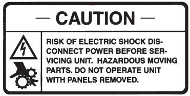
2.Note all warning labels on the freezer. If any warning labels are missing or damaged replace them immediately.
3.Do not wear loose fitting garments or jewelry which could cause a serious accident.
4.Stay alert at all times during operation.
5.Keep operating area clean.
6.Do not attempt any repairs unless the main power supply to the freezer has been disconnected. Contact Grindmaster Technical Service for service assistance.
7.Do not put objects or fingers in the dispense plunger.
8.Do not operate freezer if any excessive noise or vibration occurs. Contact your authorized service agent.
9.Be certain machine is installed with adequate space for proper air circulation. (See installation section.) Failure to provide sufficient ventilation will reduce freezer performance and void equipment warranty.
Located on the right, left and rear panels. (part # W0600218)
FREEZER APPLICATION AND SPECIFICATIONS
Model 3312
The freezer consists of two freezing cylinders with rotating internal augers (dashers) that are belt-driven by electric motors. The augers scrape frozen product off of the inside of the refrigerated cylinders. Torque sensing mechanisms control compressor operation to maintain desired product consistency. The freezer utilizes an air-cooled refrigeration system to freeze the product. Self-closing dispensing valves are attached to the front of the freezing cylinder. The unit has an adjustable consistency control and an out of product indicator for each side.
When properly operated and cared for, the Model 3312 will provide many years of service. Proper care includes regular cleaning and maintenance. To minimize the amount of maintenance necessary, follow the operating procedures outlined in this manual.
Product Tips
The Model 3312 was designed to dispense a wide variety of frozen beverages including frozen fruit juice, frozen lemonade, slush and frozen cocktails. These products can be served in consistencies ranging from thin to fairly thick.
Two types of dispensing valve plungers and product consistency springs are available depending on the thickness of the product being served. These parts are interchangeable depending upon your needs. One plunger, part W0480438 has one horizontal outlet slot and is used to serve thin to medium products such as frozen lemonade and slush. The other plunger, part W0480451 has two horizontal outlet slots and is used to serve thicker product such as neutral base frozen cocktails. A red spring, part W0631239, is used on the drive motor to adjust product consistency to serve thin to medium products. The yellow spring, part W0631238, is used for thicker product. The spring is located next to the drive motor behind the right hand side panel.
Over an extended period of time, some products, such as frozen cocktails that contain alcohol, have a tendency to separate, or stratify. Separation of product on the mix storage hopper can result in frozen product quality inconsistency. Simply keeping the product, in the mix storage hopper, stirred on a regular basis will eliminate this problem.
Page 2 |
Model 3312 |
|
|
Product Tips (cont.)
Some cappuccino or latté mixes contain dairy products which can spoil if not refrigerated. If the freezer is to be turned off at night these products must be removed from the freezer.
Contact your local health department regarding its regulations for proper mix handling and storage.
Carburetor Assembly
Your new freezer uses a metering device, known as a carburetor, to feed the proper ratio of mix and air into the freezing cylinder (and to prevent frozen product from rinsing out of the freezing cylinder).
The carburetor, or carb tube, is a tube with a hole, or series of holes, bored through the side. It is located in the hopper and fits in the hole that leads to the freezing cylinder. Air flows into the freezing cylinder through the top of the
tube and mix flows in through a smaller hole in the side |
|
|
|
|
of the carb tube. The size of the mix inlet hole can be |
|
|
|
|
balanced with the viscosity (thickness) of the liquid mix |
|
|
|
|
and product draw rate, in such a way that the proper |
|
|
|
|
amount of mix is fed into the freezer cylinder to blend |
|
|
|
|
with air at just the right ratio. Mix viscosity varies by mix |
|
|
|
|
type, mix temperature and mix age. Different serving |
|
|
|
|
rates also demand different feed rates. For many prod- |
|
|
|
|
ucts, the proper mix to air ratio is generally accepted |
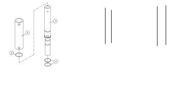
Thick product carb tube |
Standard carb tube |
Low overrun |
|
to be two parts mix to one part air. This proportion |
||||
(W0471136) |
(W0471076) |
carb tube |
||
yields a finished product that is both tasty and prof- |
||||
|
|
|
itable. At this ratio, one gallon of liquid mix will yield a |
(W0472060) |
|
Figure A |
||
volume of one and one-half gallons of frozen product. This |
||
|
additional volume is the overrun in the product. Crathco offers three versions of carb tubes (see Figure A). Depending on the product being served and overrun requirements there is a standard tube for most slush or cocktail products, a low overrun carb tube that allows all air trapped in the freezing cylinder to escape and a smoothie/shake carb tube.
This carb tube has an outer sleeve that can be rotated to line up with different hole sizes to provide various levels of overrun. Most applications only require the standard carb tube.
Mix Considerations - General
Freezing characteristics are affected by the amount of sweeteners and solids in the mix. The amount of sweeteners and solids is called BRIX. BRIX can be measured with an instrument called a refractometer. A BRIX reading of between 11 and 14 will provide optimum freezer operation. Mixes with this BRIX level will freeze down to a smooth, uniform consistency. Mixes with too high a BRIX level will take longer to freeze down and will yield a soft, wet frozen product. Mixes with too low a BRIX level will have larger ice crystals and will have a tendency to dispense slowly. Alcohol content also affects product freezing characteristics. High alcohol content may prevent the freezer from serving product at proper thickness.
Note: Always take BRIX measurement using mix that has been thoroughly blended, before it is frozen. Always allow frozen mix to thaw thoroughly before taking a reading.
For maximum output capacity, always pre-chill mix before adding it to the freezer. Pre-chilled mix gives the freezer a head start on the freezing process and will speed both initial freeze down and recovery time. It is normal for output capacity to decrease when warm mix is added, or when the freezer is operated in a warm area.
Freezer Specifications
|
Standard 3312 |
CE 3312 |
|
|
|
|
|
Dimensions |
26-3/4”H x 18-1/2”W x 29”D |
26-3/4”H x 18-1/2”W x 29”D |
|
68 cm x 47 cm x 74 cm |
68 cm x 47 cm x 74 cm |
||
(H x W x D) |
|||
(includes header box) |
(includes header box) |
||
|
|||
Electrical |
115V / 60Hz / 1 PH |
220-240V / 50 Hz / 1 PH |
|
Dedicated 20 Amp circuit |
Dedicated 15 Amp circuit |
||
|
|||
|
|
|
|
Circuit NEMA # |
5-20R |
Plugless cord (user must attach plug) |
|
|
|
|
|
Drive Motor |
1/2 hp, Capacitor Start |
1/4 hp, Capacitor Start |
|
|
|
|
|
Compressor |
3/4 hp |
3/4 hp |
|
Cooling |
Air-cooled |
Air-cooled |
|
|
|
|
|
Actual Weight |
245 lbs (111 kg) |
245 lbs (111 kg) |
|
|
|
|
|
Mix Hopper Capacity |
3 gallons (11.4 liters) |
3 gallons (11.4 liters) |
|
|
|
|
|
Freezing Cylinder Capacity |
(2) 1-1/2 gallons (5.7 liters) |
(2) 1-1/2 gallons (5.7 liters) |
|
|
|
|
|
Refrigerant |
See Serial Number Plate |
See Serial Number Plate |
|
Refrigerant Charge |
See Serial Number Plate |
See Serial Number Plate |
|
|
|
|
|
High Side (operating |
Approx. 275-350 psi |
Approx. 275-350 psi |
|
pressure /design pressure) |
|||
|
|
||
|
|
|
|
Low Side |
35-40 psi |
35-40 psi |
|
|
|
|
Model 3312 |
Page 3 |
|
|

INSTALLATION
Shipment Transit
1.The freezer has been operated and tested at the factory. Upon arrival the complete freezer must be thoroughly checked for any damage which may have occurred in transit.
Note: A Tip (N) Tell warning device is placed on each shipping carton at the factory. If the indicator is red, the carton has been tipped in transit. (See Figure B)
2.THE CARRIER IS RESPONSIBLE FOR ALL DAMAGE IN TRANSIT WHETHER VISIBLE OR CONCEALED. DO NOT PAY THE FREIGHT BILL until the freezer has been checked for damage. Have the carrier note any visible damage on the freight bill. If concealed damage and/or shortages are found later, advise the carrier within 10 days and request inspection. The customer must place any claim for damage and/or shortage with the carrier. Grindmaster cannot make any claims against the carrier.
Installing Your Unit |
Figure B |
1.Place the self-sealing rubber pad (shipped with the freezer) on a level counter that is stable and strong enough to safely support the freezer’s weight (245 lbs /111 kg), or if equipped with legs instead of pad, install legs by screwing them into the four leg holes on the bottom of the unit. (Leg Kit Part # W0890220 (4) 4” Legs)
2.Make sure freezer is to be placed in a location that is within 6’ of a properly grounded circuit and allows adequate space at each side and above for proper air circulation. Air Cooled Units Only: Minimum clearance is 6” (15 cm) on both sides and 0” at back and open above the freezer. (See Figure C)
NOTE: Failure to allow adequate ventilation will void the warranty and reduce freezer performance.
NOTE: Locating the unit in high ambient temperatures (over 100°F / 37.8°C) will Figure C significantly reduce the performance of your machine.
3.Remove the side panels and supporting all four sides, lift machine up (by the frame) and place in appropriate area on top of rubber pad.
!
!
CAUTION: If equipped with spinner do not lift unit up by spinner shaft. It will cause serious damage to spinner.
CAUTION: Beverage freezers are heavy pieces of equipment. It is recommended that moving or lifting the unit be done by two people to
avoid injury.
Figure D
4.The side panels should still be removed. Cut the cable tie on each motor used to secure motor during shipment. Make sure motors rock freely. (Figure D)
5.220V/50Hz Units: These units come with a plugless cord that requires the appropriate plug configuration be connected. This must be determined by the power outlets at the specified location. See wiring diagram at back of manual for assistance. It is recommended that a service technician performs this operation.
Page 4 |
Model 3312 |
|
|

Installing Your Unit (cont.)
6. Review hopper contents to make sure all parts are available:
Part # |
Description |
|
|
W0600170 |
Manual |
|
|
W0600073 |
Rubber Pad Sheet |
|
|
W0600121 |
Merchandiser Installation Sheet |
|
|
W0600012 |
MSDS Sanitizer Sheet |
|
|
W0600159 |
Warranty Registration Card |
|
|
W0890182 |
Drip Tray Kit |
|
|
W0520093 |
Hopper Cover |
|
|
W0480445 |
Valve Handle |
|
|
W0631230 |
Valve Spring |
|
|
* |
Carb Tube |
|
|
* |
Dispense Valve Plunger |
|
|
W0470076 |
Lubricant |
|
|
W0631903 |
Sanitizer Packets |
|
|
W0600058 |
Laminated Cleaning Instructions |
|
|
W0600327 |
Seal Installation Instructions |
|
|
*Optional items specified when the unit is ordered.
7.Fill out Warranty Registration Card with the requested information and mail to Grindmaster Corporation.
8.Replace side panels.
9.Assemble the dispense valve following the instructions on page 8. The valve plunger, spring and retaining pin come in the small parts bag.
10.Be sure ON-OFF-CLEAN switches (toggle switch located underneath the electrical box) are in the “OFF” position.
11.Connect the power cord directly to a properly grounded DEDICATED 120V/60Hz, 20 Amp circuit or 220-240V/ 50Hz, 15 Amp circuit for CE models. Do not use an extension cord.
!Do not alter or deform the plug in any way! Altering or deforming the plug may damage unit and will void warranty.
12.Remove the drip tray kit from the bubble wrap. Separate the parts and remove the protective coating. The drip tray is mounted on two screws that are located on the lower front of the freezer cabinet.
13.Place the key hole slot of the drip tray support bracket on to these screws and tighten the screws.
14.Angle the back of the drip tray surround bracket into the drip tray support bracket and lower bracket to lock it into place.
15.Place drip tray onto drip tray surround bracket.
16.Place the louvered drip tray insert into drip tray.
Model 3312 |
Page 5 |
|
|
Accessory Installation
The Model 3312 has several optional accessories that can be added to the unit in the field to meet your application’s needs. These accessories come with installation instructions.
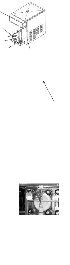
•Spinner - Spinners are typically used in applications that add flavoring to a frozen neutral base product after it is dispensed. Allows operator to serve a wider variety of frozen drinks from one machine (i.e. hazelnut added to cappuccino). See Figure E.
•Concealed Air Filter - Prevents dust from clogging the condenser. Ideal for applications near beaches. Helps maintain maximum air
flow and optimum freezer performance. See Figure F.
NSF approved. Part # W0890200 stainless steel; W0890208 black.
•Exposed Air Filter - Similar to concealed air filter. Not NSF approved. Part # W0890206. See Figure G.
•Valve Lock Security Bracket - Part # W0471135. Ideal for self-service locations to prevent unauthorized use. Lock must be purchased separately. See Figure H.
•Remote Fill Control - Automatically refill the mix storage hopper. Provide additional labor savings by pre-mixing product automatically and monitoring system to maintain the mix hopper level.
•Private Label Header - A private label or different drink header can be installed by removing two screws from the electrical box cover. Place the header (transparency) between the clear and opaque plates (plastic lens). Put these in place under the lip of the machine top. Slip the electrical box cover back on to the machine and reinsert the screws. (See Figure I) Grindmaster offers a variety of drink headers including: frozen beverage, frozen lemonade, cappuccino, margarita, pina colada, frozen cocktail, frozen daiquiri and smoothie.
OPERATION AND ADJUSTMENTS
How to Operate
1.Sanitize unit following the cleaning instructions starting on page 8.
2.Fill the mix storage hoppers following the instructions on page 10. Allow barrels to fill with product to proper level, then insert carb tube from parts bag in hole toward rear of hopper. See Figure J.
3.Turn power switch to “ON” position for each barrel.
4.Allow product to freeze in barrel. Compressor will turn off when product in both barrels reaches pre-set consistency.
5.To dispense product pull down valve handle and release when done.
6.If product consistency is not as desired, adjust per the instructions on page 7.
7.Refill mix storage hopper when “mix out” light is ON.
8.Clean the unit regularly following local health codes.
9.Perform maintenance when necessary to increase the life of the unit. See chart in this manual for regular maintenance schedule.
Mix Low Function
1.This model utilizes a simple float mechanism to sense when mix is low in hopper. (See Figure J) When the mix level in the hopper is low, the mix low light located in the front of the machine next to the valve block will illuminate. (The left-most light corresponds to the loft barrel.)
NOTE: Do not run the unit under mix low conditions for long periods of time. This can affect machine performance or damage componentry.
Spinner mounting bracket
Figure E
FILTER
SLIDE THE FILTER IN BEHIND
Figure F THE FILTER PANEL, & IN FRONT OF THE EXISTING SIDE
PANEL. TO CHANGE, REMOVE, CLEAN AND/OR REPLACE.
Figure G
Figure H
Figure I
Page 6 |
Model 3312 |
|
|
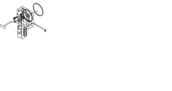
Consistency Adjustment
From time to time, it may become necessary to readjust the consistency setting (thickness) to compensate for variation between different mixes or to switch from one type of product to
another. This adjustment is made as follows:
1. Disconnect electrical power.
Mix Low Float O-ring
Carburetor
Mix Low Float
|
! |
WARNING: Do not attempt to readjust the freezer until electrical |
|
|
|
|
power has been disconnected. |
|
|
2. |
Remove right side panel (facing the freezer). |
|
|
|
3. |
Use the adjustment screw, situated on the front of the drive motor |
|
|
|
|
mounting bracket to change product thickness. Turn the thumbscrew |
|
|
|
|
(3 full turns for red spring, 1 turn for yellow spring) to make a noticeable |
|
|
|
|
change in consistency. (See Figure K) |
Figure J |
||
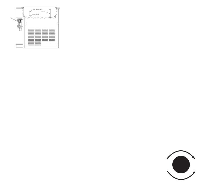
NOTE: Clockwise is for thicker product consistency and counter clockwise |
|
|
||
is for thinner product consistency. (See Figure L) |
|
|
||
4. |
Reinstall the side panel, reconnect power. |
|
Screw |
|
5. Turn freezer to “ON” and allow it to freeze to desired consistency. |
|
|
||
6. |
Check product. Repeat process until desired consistency is achieved. |
|
|
|
NOTE: When making changes to a colder (thicker) setting, recheck consistency again after the compressor has cycled off. When adjusting (counter-clockwise) to a thinner consistency, a large portion of product should be drawn from the dispense valve to reduce the product thickness below the new set point (adjustment). Then allow the freezer to refreeze product to the new setting.
Increase Thickness
(turn clockwise)
Decrease Thickness
(turn counterclockwise)
Figure L
Model 3312 |
Page 7 |
|
|
CARE AND CLEANING
Cleaning and sanitizing frequency must be followed according to state and local health department regulations.
NOTE: Each time the freezer is fully disassembled, all foodzone freezer components must be thoroughly washed and sanitized using procedures recommended by the local health department. In lieu of local health department recommendations, use a three compartment sink; one compartment to wash parts in detergent, one compartment to rinse, and one to sanitize.
Drain and Rinse
1.If the freezer is empty, proceed to Disassembly and Cleaning. If there is product in the freezer, turn either the right or left front panel switch to “CLEAN”. Most users schedule cleaning when product in the hopper is low to minimize product loss.
2.On freezers using the optional Remote Fill Control and Proportioning Pump, turn “OFF” the water valve on the Proportioning Pump, using the valve next to the inlet pressure regulator and turn the switch on the Remote Fill Control to “OFF”.
3.Open the front dispensing valve and drain all product from the freezer. Close the dispensing valve and turn freezer to “OFF”.
NOTE: Use approximately 2½ gallons (10 liters) of cool water to rinse product out of freezer.
4.Remove the carburetor tube and pour water into the storage hopper. Allow the water to fill the freezing cylinder.
5.Turn the panel switch to “CLEAN” for 5 minutes.
6.Open the dispensing valve and drain the water from the freezer.
7.Turn the freezer “OFF”.
Disassembly and Cleaning
Note: For cleaning and sanitizing before initial start-up remove carb tubes, dispense plungers, handles and springs from parts bag first.
1.Disassemble the dispensing valve assembly (Figure M). Pull out valve handle retaining pin while supporting the valve plunger from the bottom (Figure N). Push up on the valve plunger and remove the stainless handle (Figure O). Slide the valve plunger and spring downward to remove (Figure P).
2.Remove knobs and carefully remove the front dispensing valve assembly, leaving the dasher assembly in the cylinder. Remove the o-rings from the plunger assembly and back of the dispensing valve body. (See Figure Q)
|
|
|
Figure N Remove Pin Figure O Remove Handle |
|
Figure M Disassemble |
Figure P Remove |
|||
|
Dispensing Valve |
|
Plunger and Spring |
|
NOTE: The best way to remove an o-ring is to first wipe off all of the lubricant using a clean paper towel. Pinch the o-ring upward with a dry paper towel between your index finger and thumb. When a loop is formed in the o-ring, roll it out of the groove with your other thumb. Always remove the o-ring farthest from the
end of the plunger first. Carefully inspect the o-rings and replace if necessary. (See Figure Q)
3.Remove the dasher assembly from inside the freezing cylinder taking care to avoid damaging the rear seal assembly at the back of the freezing cylinder. Disassemble the dasher assembly by removing the stator rod and front and rear stator rod bearings.
Figure Q Ring Removal
Page 8 |
Model 3312 |
|
|
Disassembly and Cleaning (cont.)
4.Remove stationary half of the shaft seal assembly from the back end of the freezer cylinder. This is accomplished by reaching into the cylinder and pulling seal out with your index finger. (See Figure R)
5.Slide the rotary half of the seal off the dasher shaft. Inspect both seal components carefully for nicks or cracks. Replace seal if defective.
NOTE: To prevent leakage the surfaces of the rotary seal and the stationary seal must be smooth with no chips or cracks.
NOTE: All units are shipped with a standard ceramic seal (Part # W0340201) unless otherwise specified. Certain products contain coconut oil which requires a different sealing material. For these products use the coconut oil seal (Part # W0340210). The stationary half of the standard seal has a white polished surface. The stationary half of the coconut oil seal has a glossy black surface.
6.Remove carb tube from bottom of hopper and remove o-rings. (See Figure S).
7.Copy disassembly procedures on other side.
8.Remove drip tray and empty contents.
9.Take all components to the cleaning area.
10.Prepare 1 gallon solution of hot tap water and a good grade of dishwashing detergent.
11.Thoroughly wash all components in a warm, mild detergent solution including the
inside of the freezing cylinder and the mix storage hopper. DO NOT WASH COMPONENTS IN A DISHWASHER.
12.Use a medium sized brush to clean the bottom of the valve body and the inside of the plunger bore with detergent solution taking care to remove only remaining lubricant. (Figure T)
13.The exterior of the freezer should be cleaned as needed with a cloth towel.
CAUTION: Coarse rags, abrasive cleaners and excessive force can ! damage and/or scratch the surfaces of the freezer.
Figure R Installing the
stationary half of seal
Figure S Carb Tube
Reassembly |
|
NOTE: Allow all parts to dry completely before reassembly. |
Figure T Clean Valve Body |
|
1.Reassemble drip tray and re-install on front of unit.
2.Wet the inner rubber lip of the rotary half of the seal and the back end of
the dasher shaft with water. Slide rotary half of assembly onto the dasher shaft, RUBBER FIRST, with the smooth sealing surface facing the back of the dasher. (See Figure U). Be sure the rotary half is fully seated against the shoulder of the shaft.
3. Insert the stationary half of the seal into the ribbed rubber boot with the polished surface facing out (forward).
4. Lightly lubricate the ribbed rubber boot of the stationary ceramic seal (taking care not to get any lubricant on the polished surface) and insert it straight back into the recess at the back of the freezing cylinder, RUBBER FIRST. (See Figure V)
NOTE: The stationary half of the seal must be completely dry before reassembling. If the circular half of the seal is white, make sure that the grooved side is toward the rubber. If the circular half is black, be sure the glossy side is facing out.
5. |
Reassemble the dasher assembly, as shown in Figure W. Insert the larger front |
|
|
and smaller rear white plastic bearings into dasher, then slip in the stator rod. |
|
6. |
Carefully and slowly guide the dasher into the freezing cylinder, taking care |
|
|
not to damage the seal assembly. Turn dasher shaft until it engages the square |
Figure V Installing the |
|
drive coupling. Slide the dasher back into the cylinder so that the two smooth |
stationary half seal |
|
sealing surfaces meet. (See Figure X) |
|
7. |
Inspect and lightly lubricate the large square o-ring |
|
|
and refit it into the back of the valve block |
|
|
assembly. Install the valve assembly on the front |
|
|
studs and tighten the knobs until they are finger |
|
|
tight. Do not use tools to tighten knobs. |
|
NOTE: Failure to lightly lubricate the large o-ring can Figure W Dasher Assembly |
|
|
Figure X Seal Assembly |
||
result in product leakage. |
|
|
8. |
Copy reassembly steps on other side. |
|
|
|
|
Model 3312 |
Page 9 |
|
|
|
|
 Loading...