


XLC Rigging Manual
ELECTRO-VOICE®

Table of Contents |
|
|
Rigging-Safety Warning.............................................................................................................................................. |
2 |
|
0 Introduction .............................................................................................................................................................. |
3 |
|
1 XLC Rigging System ............................................................................................................................................... |
5 |
|
1.1 |
Overview of the XLC Flying System ........................................................................................................ |
5 |
1.2 |
Enclosure Rigging Hardware Details ....................................................................................................... |
5 |
2 XLC Rigging and Flying Techniques ..................................................................................................................... |
10 |
|
2.1 |
Array Considerations ............................................................................................................................. |
10 |
2.2 |
Rigging an Array Using the XLC Front Dollies ....................................................................................... |
10 |
3 Rigging-Strength Ratings, Safety Factors, and Special Safety Considerations ..................................................... |
15 |
|
3.1 |
Working-Load Limit (WLL) and Safety Factor Definitions ...................................................................... |
15 |
3.2 |
Structural Rating Overview .................................................................................................................... |
16 |
3.3 |
Simplified Structural-Rating Guidelines ................................................................................................. |
16 |
3.4 |
Complex Structural-Rating Analysis ...................................................................................................... |
18 |
3.5 |
Wind Loading ......................................................................................................................................... |
24 |
3.6 |
Electro-Voice Structural-Analysis Procedures ....................................................................................... |
25 |
4 Rigging Inspection and Precautions ...................................................................................................................... |
26 |
|
References |
............................................................................................................................................................... |
28 |
Notes ........................................................................................................................................................................ |
|
29 |
1 |
ELECTRO-VOICE® |

Rigging-Safety Warning
This document details general rigging practices appropriate to the entertainment industry, as they would apply to the rigging of Electro-Voice XLC loudspeaker systems. It is intended to familiarize the reader with standard rigging hardware and techniques for suspending XLC loudspeaker systems overhead. Only persons with the knowledge of proper hardware and safe rigging techniques should attempt to suspend any sound systems overhead. Prior to suspending any Electro-Voice XLC loudspeaker systems overhead, it is essential that the user be familiar with the strength ratings, rigging techniques and special safety considerations outlined in this manual. The rigging techniques and practices recommended in this manual are, of necessity, in general terms to accommodate the many variations in loudspeaker arrays and rigging configurations. As such, the user is expressly responsible for the safety of all specific XLC loudspeaker array designs and rigging configurations as implemented in practice.
All the general rigging material contained in this manual is based on the best available engineering information concerning materials and practices, as commonly recognized in the United States, and is believed to be accurate at the time of the original printing. As such, the information may not be directly applicable in other countries. Furthermore, the regulations and requirements governing rigging hardware and practices may be superseded by local regulations. It is the responsibility of the user to ensure that any Electro-Voice loudspeaker system is suspended overhead in accordance with all current federal, state and local regulations.
All specific material concerning the strength ratings, rigging techniques and safety considerations for the XLC loudspeaker systems is based on the best available engineering information concerning the use and limitations of the products. Electro-Voice continually engages in testing, research and development of its loudspeaker products. As a result, the specifications are subject to change without notice. It is the responsibility of the user to ensure that any Electro-Voice loudspeaker system is suspended overhead in accordance with the strength ratings, rigging techniques and safety considerations given in this document and any manual update notices. All non-Electro-Voice associated hardware items necessary to rig a complete XLC loudspeaker array (grids, chain hoists, building or tower supports and miscellaneous mechanical components) are the responsibility of others.
Electro-Voice
July, 2002
ELECTRO-VOICE® |
2 |
0. Introduction
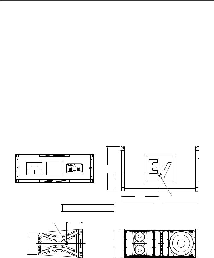
The XLC (X-Line Compact) loudspeaker systems represent an important step in line-array technology for smalland medium-scale sound reinforcement. The individual loudspeaker drivers, acoustic lenses, acoustic waveguides, enclosures and rigging hardware were all designed specifically for the XLC product line to not only achieve the highest acoustic output with the highest fidelity, but also to produce a precise wavefront from each element to achieve state-of-the- art line-array performance. A brief description of the product line is included below. The XLC loudspeaker systems are shown in Figure 1 with key dimensions and weights.
XLC-127: Three-way, LF/MB/HF loudspeaker system with a 120°H x 7.0°V coverage pattern. The system includes one DL12ST 12-inch (305-mm) LF driver, two DM65 6.5-inch (165-mm) MB drivers and two DH2T-16 2-inch (51-mm) HF drivers. The XLC-127 has a switchable crossover that allows either biamp or triamp operation. The XLC-127 utilizes an enclosure that is trapezoidal in the vertical plane (with an 8° total included angle) and has the standard XLC 8° rigging frame secured to the left and right enclosure sides.
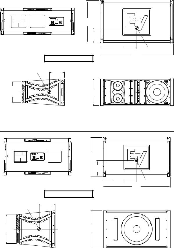
XLC-127+: Three-way, LF/MB/HF loudspeaker system with a 120°H x 7.0°V coverage pattern. The system includes one DL12ST 12-inch (305-mm) LF driver, two DM65 6.5-inch (165-mm) MB drivers and two ND6-16 3-inch (76-mm) HF drivers. The XLC-127+ has a switchable crossover that allows either biamp or triamp operation. The XLC-127+ utilizes the same 8° trapezoidal enclosure as the XLC-127 and has the same standard XLC 8° rigging frame secured to the left and right enclosure sides.
XLC-118: Subwoofer loudspeaker system with one EVX180B 18-inch (457-mm) woofer. The XLC-118 utilizes an enclosure that is trapezoidal in the vertical plane (with a 12° total included angle) and has the standard XLC 12° rigging frame secured to the left and right enclosure sides.
|
|
22.50in |
|
|
|
|
(572mm) |
|
|
|
|
8.31in |
|
|
|
|
(211mm) |
|
|
Rear View |
|
|
19.44in |
Center of Gravity |
|
|
|
(494mm) |
|
|
|
|
39.00in |
|
|
|
|
|
|
|
Weight: 116 lb (52.6 kg) |
|
(991mm) |
|
|
|
Top View |
||
|
|
|
|
|
Center of Gravity |
8.31in |
|
|
|
(211mm) |
|
|
|
|
|
Ref |
|
|
|
11.02in |
C |
14.25in |
|
|
(280mm) |
|
|
||
Cent. |
L |
(362mm) |
|
|
|
|
|
||
|
|
|
|
|
Side View |
|
Front View (Without Grille) |
||
Figure 1a: XLC-127 Loudspeaker System
3 |
ELECTRO-VOICE® |
|
|
22.50in |
|
|
|
|
(572mm) |
|
|
|
|
7.94in |
|
|
|
|
(202mm) |
|
|
Rear View |
|
|
19.56in |
Center of Gravity |
|
|
|
(497mm) |
|
|
|
|
39.00in |
|
|
|
|
|
|
|
Weight: 111 lb (50.3 kg) |
|
(991mm) |
|
|
|
Top View |
||
|
|
|
|
|
Center of Gravity |
7.94in |
|
|
|
(202mm) |
|
|
|
|
|
Ref |
|
|
|
11.02in |
|
14.25in |
|
|
(280mm) |
C |
|
|
|
Cent. |
L |
(362mm) |
|
|
|
|
|
||
Side View |
|
Front View (Without Grille) |
||
Figure 1b: XLC-127+ Loudspeaker System
|
22.50in |
|
|
|
(572mm) |
|
|
|
9.38in |
|
|
|
(238mm) |
|
|
|
Rear View |
19.50in |
Center of Gravity |
|
(495mm) |
||
|
39.00in |
||
|
|
|
|
|
|
|
(991mm) |
|
Weight: 120 lb (54.4 kg) |
|
Top View |
|
|
|
|
|
9.38in |
|
|
|
(238mm) |
|
|
Center of Gravity |
Ref |
|
|
16.64in |
C |
21.44in |
|
(423mm) |
|||
|
|||
L |
(545mm) |
||
Cent. |
|
||
|
|
Side View Front View (Without Grille)
Figure 1c: XLC-118 Loudspeaker System
ELECTRO-VOICE® |
4 |

1. XLC Rigging System
1.1 Overview of the XLC Flying System
The XLC loudspeaker systems have been designed to construct acoustic line arrays. Acoustic line arrays typically consist of independent columns of loudspeaker systems. This simplifies the rigging system.
The XLC loudspeaker enclosures utilize a hinged rigging system that makes constructing arrays easy, predictable and repeatable. This front-hinging rigging concept allows arrays to be constructed with the least possible spacing between enclosures. The front and back rigging hardware for linking two enclosures together are captured as an integral part of the side rigging frames.
A basic array is shown in Figure 2 that illustrates the integral components that make up a typical XLC flying system. The XLC enclosures are vertically trapezoidal - taller at the front than at the back. The enclosures are hinged at the front corners using rigging hardware specially designed for the XLC system. The enclosures are linked at the rear using rigging arms that have multiple attachment positions. The different positions adjust how close the back corners of the enclosures are pulled together; hence, adjusting the vertical angle of the bottom enclosure.
1.2 XLC Enclosure Rigging Hardware Details
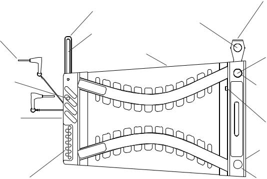
On each side of the enclosure is an XLC rigging frame assembly. All the rigging hardware needed to fly a column of XLC enclosures is an integral part of a high-strength aluminum-alloy rigging frame. The structural load is transmitted through the frame minimizing the load on the loudspeaker enclosure shell. Figure 3 illustrates the XLC enclosure rigging hardware components. Figures 4a and 4b show key dimensions for the rigging hardware.
At the front of the frame is a rectangular rigging tube. Captured inside the rigging tube is a rigging connector called the button bar. The button bar is constructed from a high-strength aluminum alloy. The button bar can slide out the top of the tube and be locked into position as shown in Figure 2. The portion of the button bar sticking out the top would be inserted into the front rigging tube of an enclosure above, linking the two enclosures together and forming a hinging point between the two enclosures. The button bar can also be fully retracted inside the tube for transportation.
Each button bar has two spring-loaded buttons that extend out of the bar. The front rigging tube has two holes that lock the buttons from the bar in place. As shown in Figure 3, the bottom button locks the button bar in place at the top of the tube. The exposed top button is then used to lock the button bar in the tube of an enclosure above. For transportation, the button bar would be slid down inside the tube and would be locked in the tube using the top button.
At the rear of the frame is a rigging slot. Captured inside the rigging slot is a rigging connector called the swing arm. The swing arm is constructed from a high-strength aluminum alloy. The swing arm can be pivoted to stick out the top as shown in Figure 3. At the bottom of the frame, the rear rigging slot has a series of holes.
5 |
ELECTRO-VOICE® |
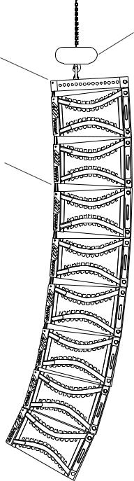
Hoist Motor
Grid
Swing Arm

 Button Bar
Eight XLC Enclosures
Hinged at the Front by
the Button Bars and
Front Rigging Tubes
Angles Between Enclosures fixed by Pins through the Swing Arms and Rear Rigging Slot Holes
 XLC Enclosures
Figure 2:
Typical XLC Flying System
The swing arm from an enclosure below can be pivoted up so that one of the quick-release pins may be inserted through the holes in the rigging slot on the frame and the slot in the swing arm, linking the two enclosures together. The vertical tilt angle of the bottom enclosure is then determined by the hole in which the swing arm is pinned. The XLC-127 and XLC-127+ enclosures may be angled from 0° to 8° in 1° increments, while the XLC-118 enclosure may be angled from 0° to 12° in 1° increments. The angle adjustment holes are detailed in figures 4a and 4b. This pin fixes the maximum distance the back corners of the enclosures may be separated.
ELECTRO-VOICE® |
6 |
Specifically, this means that when the enclosures are suspended, the back of the bottom enclosure will rotate down until the pin is stopped at the end of the slot in the swing arm. This one pin will not prevent the back corners of the enclosures from coming together. When landed, the enclosures will compress together until their back corners touch. The enclosures can be locked apart by inserting a second quick-release pin in the rear rigging holes directly above the first pin at the end of the swing arm as shown in Figure 5. With a second pin, the swing arm becomes immobile and the array becomes rigid so that when it is landed, the enclosures are locked at the selected angles.
Two quick-release pins on lanyards are attached to the rear rigging frame for pinning the swing arm. An XLC system can often be flown using only a single pin - the one that passes through the slot in the swing arm. The choice of whether to add the second pin is left to the user. This decision is often based on personal preferences regarding the technique of transferring the enclosures from the array to dollies for transport in touring applications. In some situations, however, the second pin is required. Two pins must always be used whenever a pull back is necessary to tilt the entire array downward more than gravity will allow. If a second pin is not used, the shape of the array will change as the pull back is applied. Another example where a second pin is required is when an array with a large vertical arc is created. Gravity may not allow all the enclosures to be angled apart as much as necessary. In this case, the second pin is necessary to hold the enclosures apart to achieve the desired array shape. If the user decides not to use the second pin to hold enclosures apart at the rear, the pin should be installed in the swing-arm transport hole to prevent it from dangling and catching on something or getting in the way. Using this hole, the swing arm may be pivoted down into the rigging slot on the frame and pinned into its fully retracted position for transport.
Rear Swing Arm
Quick-Release Pins to |
|
Top Spring-Loaded |
|
Locking Button |
|
Lock Swing Arm in Rear |
|
|
Swing-Arm Slot |
|
|
Rigging Slot |
|
|
|
Bottom Spring- |
|
|
|
|
|
XLC Enclosure |
Loaded Locking |
|
Button |
|
|
|
|
Swing-Arm |
|
|
Transport Hole |
|
Hole in Rigging |
|
|
|
|
|
Tube for Locking |
|
|
Button |
Rear Rigging Slot |
|
|
Holes in Rigging Slot to Pin the Swing Arm from the Box Below
Figure 3a:
XLC Rigging Hardware
7
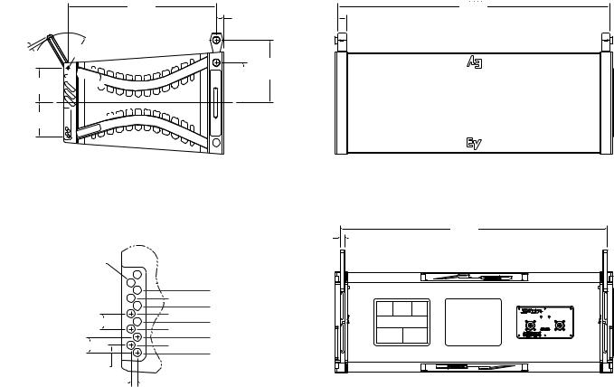
20.90in
(531mm)
0.38in |
R4.94in (125mm) |
(9.7mm) |
4.88in (124mm) 
4.75in (121mm) 


1.00in
(25.4mm)
Typ.
5.63in |
8.75in |
(222mm) |
(143mm) |
|
Typ. |
C |
|
|
|
L |
1.22in |
38.22in |
(971mm) |
|
(31.0mm) |
Cent. |
Typ. |
|
Side View |
|
|
Front View (With Grille) |
|
|
|
37.53in |
|
|
0.65in |
(953mm) |
|
|
(16.5mm) |
Cent. |
Dia .385in |
|
Typ. |
|
(9.8mm) |
|
|
|
(11 Plcs.) |
|
8° Hole |
|
|
7° Hole |
|
|
|
6° Hole |
|
|
|
5° Hole |
|
|
.730in (18.5mm) Typ. |
4° Hole |
|
|
3° Hole |
|
||
|
2° Hole |
|
|
.730in (18.5mm) Typ. |
1° Hole |
|
|
0° Hole |
|
||
|
|
|
|
.365in (9.3mm) |
|
|
|
.300in (7.6mm) |
|
|
|
Hole Detail |
|
|
Rear View |
Scale = 3:1 |
|
|
|
Figure 4a:
XLC-127 and XLC-127+ Rigging Dimensions
ELECTRO-VOICE® |
8 |
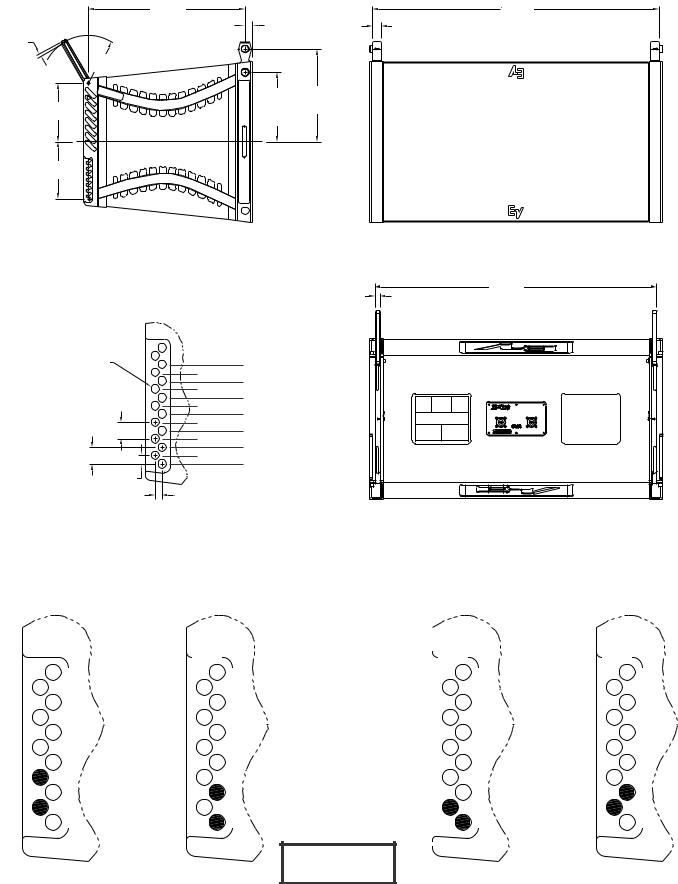
20.90in |
1.00in |
|
|
38.22in |
(531mm) |
|
1.22in |
(971mm) |
|
|
(25.4mm) |
Cent. |
||
0.32in |
Typ. |
|
(31.0mm) |
|
(8.1mm) |
|
|
Typ. |
|
R6.30in (160mm) |
|
|
|
|
|
9.22in |
12.34in |
|
|
7.79in (198mm) |
(234mm) (313mm) |
|
|
|
Typ. |
|
|
|
|
|
|
|
|
|
|
|
C |
|
|
|
|
L |
|
|
7.67in (195mm) |
|
|
|
|
Side View |
|
|
Front View (With Grille) |
|
|
|
|
0.65in |
37.53in |
|
|
|
(953mm) |
|
|
|
|
(16.5mm) |
|
|
|
|
Cent. |
|
|
|
|
Typ. |
|
|
|
|
|
|
Dia .385in |
|
|
12° Hole |
|
(9.8mm) |
|
11° Hole |
|
|
|
|
|
||
(15 Plcs.) |
|
10° Hole |
|
|
|
9° Hole |
|
||
|
|
7° Hole |
8° Hole |
|
|
|
6° Hole |
|
|
|
|
5° Hole |
|
|
.737in (18.7mm) Typ. |
|
4° Hole |
|
|
|
3° Hole |
|
||
|
|
2° Hole |
|
|
.737in (18.7mm) Typ. |
|
1° Hole |
|
|
|
0° Hole |
|
||
.368in |
|
|
|
|
|
|
|
|
|
(9.4mm) |
.300in (7.6mm) |
|
||
|
|
|||
Hole Detail
Scale = 3:1
Rear View
Figure 4b:
XLC-118 Rigging Dimensions
|
CORRECT |
|
|
|
|
|
|
|
INCORRECT |
|||
|
|
|
|
|
|
|
|
|
|
|
|
|
|
|
|
|
|
|
|
|
|
|
|
|
|
|
|
|
|
|
|
|
|
|
|
|
|
|
|
|
|
|
|
|
|
|
|
|
|
|
|
|
|
|
|
|
|
|
|
|
|
|
|
|


 = Pin
= Pin
Figure 5:
Dual Locking Pin Rigging Configurations
9 |
ELECTRO-VOICE® |
 Loading...