


ZyXEL Communications XGS-4728F User Manual
XGS-4728F
Intelligent Layer 3+ Switch
Default Login Details
IP Address http://192.168.0.1
(Out-of-band
MGMT port)
http://192.168.1.1
(In-band ports)
User Name admin
Password 1234
Firmware Version 3.90
Edition 2, 04/2010
www.zyxel.com
www.zyxel.com
Copyright © 2010
ZyXEL Communications Corporation

About This User's Guide
About This User's Guide
Intended Audience
This manual is intended for people who want to configure the Switch using the
web configurator.
Related Documentation
• Web Configurator Online Help
The embedded Web Help contains descriptions of individual screens and
supplementary information.
• Command Reference Guide
The Command Reference Guide explains how to use the Command-Line
Interface (CLI) and CLI commands to configure the Switch.
Note: It is recommended you use the web configurator to configure the Switch.
• Support Disc
Refer to the included CD for support documents.
Documentation Feedback
Send your comments, questions or suggestions to: techwriters@zyxel.com.tw
Thank you!
The Technical Writing Team , ZyXEL Communications Corp.,
6 Innovation Road II, Science-Based Industrial Park, Hsinchu, 30099, Taiwan.
Need More Help?
More help is available at www.zyx el.com.
XGS-4728F User’s Guide
3

About This User's Guide
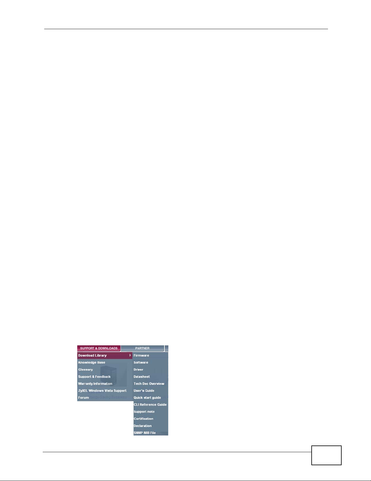
• Download Library
Search for the latest product updates and documentation from this link. Read
the Tech Doc Overview to find out how to efficiently use the User Guide, Quick
Start Guide and Command Line Interface Reference Guide in order to better
understand how to use your product.
• Knowledge Base
If you have a specific question about your product, the answer may be here.
This is a collection of answers to previously asked questions about ZyXEL
products.
•Forum
This contains discussions on ZyXEL prod ucts. Learn from others who use ZyXEL
products and share your experiences as well.
Customer Support
Should problems arise that cannot be solved by the methods listed above, you
should conta ct your vendor. If you cannot contact your vendor, then contact a
ZyXEL office for the region in which you bought the device.
See http://www.zyxel.com/web/contact_us.php for contact information. Please
have the following informatio n ready when you contact an office.
• Product model and serial number.
•Warranty Information.
• Date that you received your device.
• Brief description of the problem and the steps you took to solve it.
4
XGS-4728F User’s Guide

Document Conventions
Document Conventions
Warnings and Notes
These are how warnings and notes are shown in this User’s Guide.
Warnings tell you about things that could harm you or your device.
Note: Notes tell you other important information (for example, other things you may
need to configure or helpful tips) or recommendations.
Syntax Conventions
• The XGS-4728F may be referred to as the “Switch”, the “device”, the “system”
or the “product” in this User’s Guide.
• Product labels, screen names, field labels and field choices are all in bold font.
• A key stroke is denoted by square brackets and uppercase text, for example,
[ENTER] means the “enter” or “ret urn” key on your keyboard.
• “Enter” means for you to type one or more characters and then press the
[ENTER] key. “Select” or “choose” means for you to use one of the predefined
choices.
• A right angle bracket ( > ) within a screen name denotes a mouse click. For
example, Maintenance > Log > Log Setting means you first click
Maintenance in the navigation panel, then the Log sub menu and finally the
Log Setting tab to get to that screen.
• Units of measurement may denote the “metric” value or the “scientific” value.
For example, “k” for kilo may denote “1000” or “1024”, “M” for mega may
denote “1000000” or “1048576” and so on.
XGS-4728F User’s Guide
5
Document Conventions
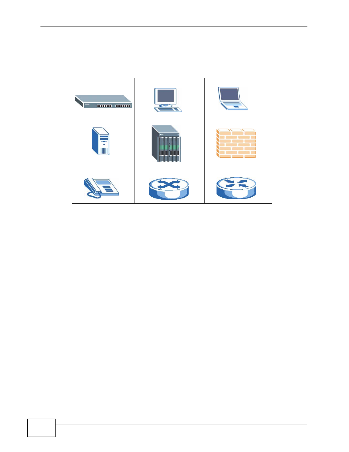
Icons Used in Figures
Figures in this User’s Guide may use the following generic icons. The S witch icon is
not an exact representation of your device.
The Switch Computer Notebook computer
Server DSLAM Firewall
Telephone Switch Router
6
XGS-4728F User’s Guide

Safety Warnings
Safety Warnings
• Do NOT use this product near water, for example, in a wet basement or near a swimming
pool.
• Do NOT expose your device to dampness, dust or corrosive liquids.
• Do NOT store things on the device.
• Do NOT install, use, or service this device during a thunderstorm. There is a remote risk
of electric shock from lightning.
• Connect ONLY suitable accessories to the device.
• Do NOT open the device or unit. Opening or removing covers can expose you to
dangerous high voltage points or other risks. ONLY qualified service personnel should
service or disassemble this device. Please contact your vendor for further information.
• For continued protection against risk of fire replace only with same type and rating of
fuse.
• Make sure to connect the cables to the correct ports.
• Place connecting cables carefully so that no one will step on them or stumble over them.
• Always disconnect all cables from this device before servicing or disassembling.
• Use ONLY an appropriate power adaptor or cord for your device. Connect it to the right
supply voltage (for example, 110V AC in North America or 230V AC in Europe).
• Do NOT allow anything to rest on the power adaptor or cord and do NOT place the
product where anyone can walk on the power adaptor or cord.
• Do NOT use the device if the power adaptor or cord is damaged as it might cause
electrocution.
• If the power adaptor or cord is damaged, remove it from the device and the power
source.
• Do NOT attempt to repair the power adaptor or cord. Contact your local vendor to order a
new one.
• Do not use the device outside, and make sure all the connections are indoors. There is a
remote risk of electric shock from lightning.
• Do NOT obstruct the device ventilation slots, as insufficient airflow may harm your
device.
Your product is m arked with this symbol, which is known as the WEEE mark. WEEE
stands for Waste Electronics and Electrical Equipment. It means that used electrical
and electronic products should not be mixed with general waste. Used electrical
and electronic equipment should be treated separately.
XGS-4728F User’s Guide
7

Safety Warnings
8
XGS-4728F User’s Guide

Contents Overview
Contents Overview
Introduction ............................................................................................................................23
Getting to Know Your Switch .....................................................................................................25
Hardware Installation and Connection ................................... ................................. ................... 31
Hardware Overview ................................................................................................................... 35
Basic Configuration ...............................................................................................................43
The Web Configurator ............................................................................................................... 45
Initial Setup Example ................................................................................................................. 55
Tutorials ..................................................................................................................................... 61
System Status and Port Statistics .................................... ..........................................................71
Basic Setting ............................................................................................................................. 77
Advanced Setup .....................................................................................................................93
VLAN ......................................................................................................................................... 95
Static MAC Forward Setup .......................................................................................................115
Static Multicast Forward Setup .................................................................................................119
Filtering ..................................... .................................................... ........................................... 123
Spanning Tree Protocol ................... ... ... ... ... .... ........................................................................ 125
Bandwidth Control .... ... ... .... ... ... ... ............................................................................................ 145
Broadcast Storm Control ......................................................................................................... 149
Mirroring .................................................................................................................................. 151
Link Aggregation ................. .....................................................................................................153
Port Authentication ...... ... .... ... ..................................................................................................163
Port Security .................................... ... ... ... ............................................. .... ... ... ... .... ... ..............169
Classifier ................................... .................................................... ........................................... 173
Policy Rule .............................................................................................................................. 179
Queuing Method ...................................................................................................................... 187
VLAN Stacking ......................................................................................................................... 191
Multicast ..................................................................................................................................199
AAA ......................................................................................................................................... 215
IP Source Guard ...................................................................................................................... 231
Loop Guard ..................... .... ... ... ............................................. .... ... ... ... ... .... ... ... ... .... .................255
VLAN Mapping ........................................................................................................................ 259
Layer 2 Protocol Tunneling .............. ... ... ... ... .... ... ... ... .... ... ... ... .................................................. 263
Private VLAN ............................ ... .... ... ... ... ............................................. .... ... ... ... ..................... 267
XGS-4728F User’s Guide
9

Contents Overview
IP Application .......................................................................................................................271
Static Route ............................................................................................................................. 273
RIP ............................... .................... ................... ................... .................... ..............................275
OSPF .............................. .................................................... ..................................................... 277
IGMP .......................................................................................................................................291
DVMRP ..................................... ....................... ...................... ....................... ........................... 295
Differentiated Services ........................................ ... ... .... ... ... ... .... ... ........................................... 299
DHCP ...................................................................................................................................... 307
VRRP .............................. .................... ................... .................... ................... ........................... 317
Management .........................................................................................................................327
Maintenance ............................................................................................................................ 329
Access Control ........................................................................................................................ 337
Diagnostic .................................... ....................................................... ..................................... 357
Syslog ....................................... .................................................... ........................................... 359
Cluster Management .......... ... ................................................ .... ... ... ........................................ 363
MAC Table ............................................................................................................................... 371
IP Table .................................. ... ... .... ... ... ... ............................................. .... ... ... ... .... .................375
ARP Table .............................. ... ... .... ... ... ... ............................................. .... ... ... ... .... ... ..............379
Routing Table ........................................................................................................................... 381
Configure Clone ....................................................................................................................... 383
Troubleshooting & Product Specifications .......................................................................385
Troubleshooting ..................................................... .................................................................. 387
Product Specifications ............................................................................................................. 393
Appendices and Index .........................................................................................................403
10
XGS-4728F User’s Guide

Table of Contents
Table of Contents
About This User's Guide..........................................................................................................3
Document Conventions............................................................................................................5
Safety Warnings ........................................................................................................................7
Contents Overview ...................................................................................................................9
Table of Contents....................................................................................................................11
Part I: Introduction................................................................................. 23
Chapter 1
Getting to Know Your Switch.................................................................................................25
1.1 Introduction ......................... ... .... ... ... ... ............................................. .... ... ... ... .... ... ... .............25
1.1.1 Bridging Example ......... .... ... ... ... ... .... ... ... ... .... ................................................ ... ... .... ... 25
1.1.2 High Performance Switching Example .......................................................................26
1.1.3 Gigabit Ethernet to the Desktop ................................................................................. 27
1.1.4 IEEE 802.1Q VLAN Application Example .................................................................. 27
1.2 Ways to Manage the Switch ............................ ... .............................................. ... ... ... ... .... ... 28
1.3 Good Habits for Managing the Switch ................................................................................. 28
Chapter 2
Hardware Installation and Connection .................................................................................31
2.1 Freestanding Installation ..................................................................................................... 31
2.2 Mounting the Switch on a Rack .......................................................................................... 32
2.2.1 Rack-mounted Installation Requirements .................................................................. 32
2.2.2 Attaching the Mounting Brackets to the Switch ................................ .......................... 32
2.2.3 Mounting the Switch on a Rack .................................................................................. 33
Chapter 3
Hardware Overview.................................................................................................................35
3.1 Front Panel Connections ... ... .... ... ... ... ... .... ... ................................................ .... ... ................ 35
3.1.1 Dual Personality Interfaces ........................................................................................ 35
3.1.2 1000Base-T Ports ...................................................................................................... 36
3.1.3 Mini-GBIC Slots .........................................................................................................36
3.2 Rear Panel .................... ... ............................................. ... .... ... ... ... ... .................................... 38
3.2.1 Power Connector ................................................... .... ... ... ... ... .... ... ... .......................... 39
XGS-4728F User’s Guide
11

Table of Contents
3.2.2 External Backup Power Supply Connector ................................................................ 41
3.2.3 Console Port ......................................................... .... ... ... ... ... .... ... ... .......................... 41
3.3 LEDs ................................................................................................................................ 41
Part II: Basic Configuration................................................................... 43
Chapter 4
The Web Configurator............................................................................................................45
4.1 Introduction ......................... ... .... ... ... ... ............................................. .... ... ... ... .... ... ... .............45
4.2 System Login ....................................................................................................................45
4.3 The Status Screen .......................................................................................................... 46
4.3.1 Change Your Password .......................................................................................... 51
4.4 Saving Your Configuration ...................................................................................................51
4.5 Switch Lockout .............................................. ... .... ... ... ............................................. .......... 52
4.6 Resetting the Switch ............................... ... ... ... .............................................. ... ... ... ... ....... 52
4.6.1 Reload the Configuration File .................................................................................... 52
4.7 Logging Out of the Web Configurator ................................................................................. 54
4.8 Help ................................................... ... .... ... ... ............................................. .... ... ................54
Chapter 5
Initial Setup Example..............................................................................................................55
5.1 Overview ............. ............................................. ... .... ... ... ... .... ................................................ 55
5.1.1 Configuring an IP Interface ........................................................................................55
5.1.2 Configuring DHCP Server Settings .. ... ....................................................................... 57
5.1.3 Creating a VLAN ........................................................................................................ 57
5.1.4 Setting Port VID .................................................. ... .... ... ... ..........................................59
5.1.5 Enabling RIP ................ .... ... ... ............................................. ... .... ... ... ... .... ... ... ... ... .......60
Chapter 6
Tutorials...................................................................................................................................61
6.1 How to Use DHCP Snooping on the Switch ........................................................................ 61
6.2 How to Use DHCP Relay on the Switch .............................................................................. 65
6.2.1 DHCP Relay Tutorial Introduction .............................................................................. 65
6.2.2 Creating a VLAN ........................................................................................................ 66
6.2.3 Configuring DHCP Relay .............................................. ... ... ....................................... 69
6.2.4 Troubleshooting ............................................... ... ... .... ... ... ... ....................................... 69
Chapter 7
System Status and Port Statistics.........................................................................................71
12
7.1 Overview ............. ............................................. ... .... ... ... ... .... ................................................ 71
7.2 Port Status Summary ............................................................................................ ... ....... 71
XGS-4728F User’s Guide

Table of Contents
7.2.1 Status: Port Details ................................................................................................73
Chapter 8
Basic Setting ..........................................................................................................................77
8.1 Overview ............. ............................................. ... .... ... ... ... .... ................................................ 77
8.2 System Information ........................................................................................................... 78
8.3 General Setup ................................................................................................. ... ... .......... 80
8.4 Introduction to VLANs ........... .... ... ....................................................................................... 82
8.4.1 Smart Isolation ................. ... ... ............................................. ... .... ... ... ... .... ... ... ... ... .......83
8.5 Switch Setup Screen ... ... ... ... .... .......................................................................................... 84
8.6 IP Setup ............................................................................................................................ 86
8.6.1 IP Interfaces .......... ... ... .... ... ... ............................................. ... .... ... ... ... .... ... ................ 86
8.7 Port Setup ................ .... ... ... ............................................. .... ... ... ... ... .... ................................ 89
Part III: Advanced Setup........................................................................ 93
Chapter 9
VLAN........................................................................................................................................95
9.1 Introduction to IEEE 802.1Q Tagged VLANs .................................................................. 95
9.1.1 Forwarding Tagged and Untagged Frames ................................................................ 95
9.2 Automatic VLAN Registration ................................ ... ... ... .... ... ... ... ... .................................... 96
9.2.1 GARP . .... ... ... ... .... ... ... ............................................. .... ... ... .......................................... 96
9.2.2 GVRP . .... ... ... ... .... ... ... ............................................. .... ... ... .......................................... 96
9.3 Port VLAN Trunking ........... ............................................. .... ... ... ... ... .... ................................ 97
9.4 Select the VLAN Type .... ... ... .... ... ............................................. ... ... .... ... ... ... .... ... ... ... ..........98
9.5 Static VLAN . .... ... ... ... .............................................. ... ... ... .... ................................................ 98
9.5.1 VLAN Status ..............................................................................................................99
9.5.2 VLAN Details ................................ .... ... ... ... .... ... ... ............................................. ... .... . 100
9.5.3 Configure a Static VLAN ...................................................................................... 100
9.5.4 Configure VLAN Port Settings .............................................................................. 102
9.6 Subnet Based VLANs .......................................................................................................103
9.7 Configuring Subnet Based VLAN ..... ................................................. ... ... ........................ 104
9.8 Protocol Based VLANs ...................................... .... ... ........................................................106
9.9 Configuring Protocol Based VLAN ............................................. ... .... ... ... ... .... ... ... ... ........107
9.10 Create an IP-based VLAN Example ................................................................................ 109
9.11 Port-based VLAN Setup ................................................................................................110
9.11.1 Configure a Port-based VLAN ................................................................................110
Chapter 10
Static MAC Forward Setup...................................................................................................115
10.1 Overview ...........................................................................................................................115
XGS-4728F User’s Guide
13

Table of Contents
10.2 Configuring Static MAC Forwarding ............................................................................115
Chapter 11
Static Multicast Forward Setup............................................................................................119
11.1 Static Multicast Forwarding Overview ...............................................................................119
11.2 Configuring Static Multicast Forwarding ........................................................................... 120
Chapter 12
Filtering..................................................................................................................................123
12.1 Configure a Filtering Rule ..............................................................................................123
Chapter 13
Spanning Tree Protocol........................................................................................................125
13.1 STP/RSTP Overview ..................................................................................................... 125
13.1.1 STP Terminology ................................................................................................... 125
13.1.2 How STP Works .................................................................................................... 126
13.1.3 STP Port States .....................................................................................................127
13.1.4 Multiple RSTP ......................................................................................................127
13.1.5 Multiple STP ........................................................................................................... 128
13.2 Spanning Tree Protocol Status Screen ............................................................................ 131
13.3 Spanning Tree Configuration ..........................................................................................131
13.4 Configure Rapid Spanning Tree Protocol ..................................................................... 132
13.5 Rapid Spanning Tree Protocol Status ........................................................................... 134
13.6 Configure Multiple Rapid Spanning Tree Protocol ........................................................ 136
13.7 Multiple Rapid Spanning Tree Protocol Status .......................................................... 138
13.8 Configure Multiple Spanning Tree Protocol .................................................................. 140
13.9 Multiple Spanning Tree Protocol Status .....................................................................143
Chapter 14
Bandwidth Control................................................................................................................145
14.1 Bandwidth Control Overview ......................................................................................... 145
14.1.1 CIR and PIR ........................................................................................................... 145
14.2 Bandwidth Control Setup ................................................................................................. 146
Chapter 15
Broadcast Storm Control.....................................................................................................149
15.1 Broadcast Storm Control Setup ...................................................................................... 149
Chapter 16
Mirroring................................................................................................................................151
16.1 Port Mirroring Setup ....................................................................................................... 151
Chapter 17
Link Aggregation ..................................................................................................................153
14
XGS-4728F User’s Guide

Table of Contents
17.1 Link Aggregation Overview ........................ ....................... ...................... ....................... . 153
17.2 Dynamic Link Aggregation ..............................................................................................153
17.2.1 Link Aggregation ID ............................................................................................... 154
17.3 Link Aggregation Status ....................................................... .......................... .................155
17.4 Link Aggregation Setting ................................................................................................ 157
17.5 Link Aggregation Control Protocol ................................................................................ 159
17.6 Static Trunking Example ..................................................................................................160
Chapter 18
Port Authentication...............................................................................................................163
18.1 Port Authentication Overview ......................................................................................... 163
18.1.1 IEEE 802.1x Authentication ................................................................................... 163
18.1.2 MAC Authentication ............................................................................................... 164
18.2 Port Authentication Configuration ............................ ....................................................... .165
18.2.1 Activate IEEE 802.1x Security ........................................................................... 166
18.2.2 Activate MAC Authentication ................................................................................. 167
Chapter 19
Port Security..........................................................................................................................169
19.1 About Port Security ..........................................................................................................169
19.2 Port Security Setup .............................. ....................... ....................... ................... ........... 170
19.3 VLAN MAC Address Limit .............................................................................................. 171
Chapter 20
Classifier................................................................................................................................173
20.1 About the Classifier and QoS .......................................................................................... 173
20.2 Configuring the Classifier ...............................................................................................173
20.3 Viewing and Editing Classifier Configuration ................................. .................................. 176
20.4 Classifier Example ...........................................................................................................178
Chapter 21
Policy Rule............................................................................................................................179
21.1 Policy Rules Overview ....................................................................................................179
21.1.1 DiffServ .................................................................................................................. 179
21.1.2 DSCP and Per-Hop Behavior ................................................................................. 179
21.2 Configuring Policy Rules ................................................................................................. 180
21.3 Viewing and Editing Policy Configuration ........................................................................ 183
21.4 Policy Example ................................................................................................................ 185
Chapter 22
Queuing Method....................................................................................................................187
22.1 Queuing Method Overview ............................................................................................. 187
22.1.1 Strictly Priority ........................................................................................................187
XGS-4728F User’s Guide
15

Table of Contents
22.1.2 Weighted Fair Queuing .......................................................................................... 187
22.1.3 Weighted Round Robin Scheduling (WRR) ........................................................... 188
22.2 Configuring Queuing ........................................................................................................ 189
Chapter 23
VLAN Stacking......................................................................................................................191
23.1 VLAN Stacking Overview ................................................................................................ 191
23.1.1 VLAN Stacking Example ........................................................................................ 191
23.2 VLAN Stacking Port Roles ................ ... .... ........................................................................ 192
23.3 VLAN Tag Format .......... ..................................................................................................193
23.3.1 Frame Format ........................................................................................................193
23.4 Configuring VLAN Stacking ............................................................................................. 194
23.4.1 Port-based Q-in-Q .................................................................................................. 195
23.4.2 Selective Q-in-Q .................................................................................................... 196
Chapter 24
Multicast ................................................................................................................................199
24.1 Multicast Overview ......................................................................................................... 199
24.1.1 IP Multicast Addresses ........................................................................................... 199
24.1.2 IGMP Filtering ........................................................................................................ 199
24.1.3 IGMP Snooping ..................................................................................................... 200
24.1.4 IGMP Snooping and VLANs ................................................................................... 200
24.2 Multicast Status .............................................................................................................. 200
24.3 Multicast Setting .............. ... .... ... ................................................ ... .... .............................. 201
24.4 IGMP Snooping VLAN .................................................................................................... 203
24.5 IGMP Filtering Profile ..................................................................................................... 205
24.6 MVR Overview ................................................................................................................ 207
24.6.1 Types of MVR Ports ............................................................................................... 207
24.6.2 MVR Modes ........................................................................................................... 208
24.6.3 How MVR Works .................................................................................................... 208
24.7 General MVR Configuration ............................................................................................ 209
24.8 MVR Group Configuration ...............................................................................................211
24.8.1 MVR Configuration Example ... ... .... ... ..................................................................... 212
Chapter 25
AAA........................................................................................................................................215
25.1 Authentication, Authorization and Accounting (AAA) ...................................................... 215
25.1.1 Local User Accounts .................. .... ... ... ... .... ... ................................................ ... .... . 216
25.1.2 RADIUS and TACACS+ ........................................................................................ 216
25.2 AAA Screens ................................................................................................................... 216
25.2.1 RADIUS Server Setup .......................................................................................... 217
25.2.2 TACACS+ Server Setup ..................................................................................... 219
25.2.3 AAA Setup .............................................................................................................. 221
16
XGS-4728F User’s Guide

Table of Contents
25.2.4 Vendor Specific Attribute ........................................................................................ 224
25.2.5 Tunnel Protocol Attribute ........................................................................................ 225
25.3 Supported RADIUS Attributes ......................................................................................... 226
25.3.1 Attributes Used for Authentication ............................ ............ .......... .......... ......... ..... 226
25.3.2 Attributes Used for Accounting ............................................................................... 227
Chapter 26
IP Source Guard ....................................................................................................................231
26.1 IP Source Guard Overview .............................................................................................. 231
26.1.1 DHCP Snooping Overview ..................................................................................... 232
26.1.2 ARP Inspection Overview ...................................................................................... 234
26.2 IP Source Guard .............................................................................................................. 235
26.3 IP Source Guard Static Binding ....................................................................................... 236
26.4 DHCP Snooping .............................................................................................................. 238
26.5 DHCP Snooping Configure ...................... ........................................................................ 241
26.5.1 DHCP Snooping Port Configure ............................................................................. 243
26.5.2 DHCP Snooping VLAN Configure .......................................................................... 244
26.6 ARP Inspection Status .....................................................................................................246
26.6.1 ARP Inspection VLAN Status .................................................................................247
26.6.2 ARP Inspection Log Status .................................................................................... 248
26.7 ARP Inspection Configure ............................................................................................... 249
26.7.1 ARP Inspection Port Configure .............................................................................. 251
26.7.2 ARP Inspection VLAN Configure ........................................................................... 253
Chapter 27
Loop Guard............................................................................................................................255
27.1 Loop Guard Overview .....................................................................................................255
27.2 Loop Guard Setup ...........................................................................................................257
Chapter 28
VLAN Mapping ......................................................................................................................259
28.1 VLAN Mapping Overview ............................................................................................... 259
28.1.1 VLAN Mapping Example ........................................................................................ 259
28.2 Enabling VLAN Mapping ................................................................................................. 260
28.3 Configuring VLAN Mapping ............................................................................................. 261
Chapter 29
Layer 2 Protocol Tunneling..................................................................................................263
29.1 Layer 2 Protocol Tunneling Overview ............................................................................. 263
29.1.1 Layer 2 Protocol Tunneling Mode .......................................................................... 264
29.2 Configuring Layer 2 Protocol Tunneling .................................................................. ... .... . 265
Chapter 30
Private VLAN.........................................................................................................................267
XGS-4728F User’s Guide
17

Table of Contents
30.1 Private VLAN Overview .................................................................................................. 267
30.2 Configuring Private VLAN ................................................................................................ 268
Part IV: IP Application.......................................................................... 271
Chapter 31
Static Route...........................................................................................................................273
31.1 Configuring Static Routing ............................................................................................. 273
Chapter 32
RIP..........................................................................................................................................275
32.1 RIP Overview ................................................................................................................... 275
32.2 Configuring RIP ............................................................................................................... 275
Chapter 33
OSPF......................................................................................................................................277
33.1 OSPF Overview .............................................................................................................. 277
33.1.1 OSPF Autonomous Systems and Areas . .... ... ... ... .... .............................................. 277
33.1.2 How OSPF Works ... ............................................. .... ... ... ... ... .... ... ........................... 278
33.1.3 Interfaces and Virtual Links .................................................................................... 278
33.1.4 OSPF and Router Elections ...................................................................................279
33.1.5 Configuring OSPF .................................................................................................279
33.2 OSPF Status ................................................................................................................. 280
33.3 OSPF Configuration .......................................................................................................282
33.4 Configure OSPF Areas ................................................................................................... 283
33.4.1 View OSPF Area Information Table ....................................................................... 284
33.5 Configuring OSPF Redistribution ................................................................................... 285
33.6 Configuring OSPF Interfaces .......................................................................................... 286
33.7 OSPF Virtual-Links ....................................................................................................... 288
Chapter 34
IGMP.......................................................................................................................................291
34.1 IGMP Overview ............................................................................................................... 291
34.1.1 How IGMP Works ................. ... ... .... ... ... ... .... ... ............................................. ... ... .... . 292
34.2 Port-based IGMP ............................................................................................................. 293
34.3 Configuring IGMP ............................................................................................................ 294
Chapter 35
DVMRP...................................................................................................................................295
35.1 DVMRP Overview ............................................................................................................295
35.2 How DVMRP Works ... ... ... ... .... ... ... ... ... .... ... ... ... .... ................................................ ... ... .....295
18
XGS-4728F User’s Guide

Table of Contents
35.2.1 DVMRP Terminology ............................................................................................. 296
35.3 Configuring DVMRP ....................................................................................................... 296
35.3.1 DVMRP Configuration Error Messages ........................................... .... ... ... ... ........297
35.4 Default DVMRP Timer Values ........................................................................................ 298
Chapter 36
Differentiated Services.........................................................................................................299
36.1 DiffServ Overview ...........................................................................................................299
36.1.1 DSCP and Per-Hop Behavior ................................................................................. 299
36.1.2 DiffServ Network Example .................................................................................... 300
36.2 Two Rate Three Color Marker Traffic Policing ................................................................. 300
36.2.1 TRTCM - Color-blind Mode .................................................................................... 301
36.2.2 TRTCM - Color-aware Mode .......................................... ........................................ 301
36.3 Activating DiffServ .......................................................................................................... 302
36.3.1 Configuring 2-Rate 3 Color Marker Settings ......................................................... 303
36.4 DSCP-to-IEEE 802.1p Priority Settings ....... .............................................. ... ... ... ... .....305
36.4.1 Configuring DSCP Settings ............................ .......................................... .............. 306
Chapter 37
DHCP......................................................................................................................................307
37.1 DHCP Overview ............................................................................................................. 307
37.1.1 DHCP Modes ........................................................................................................307
37.1.2 DHCP Configuration Options ................................................................................. 307
37.2 DHCP Status ................................................................................................................... 308
37.3 DHCP Server Status Detail ............................................................................................. 308
37.4 DHCP Relay ....... ... .... ... ... ... .... ... ... ... ... ............................................................................ 310
37.4.1 DHCP Relay Agent Information ............................................................................. 310
37.4.2 Configuring DHCP Global Relay .............................................................................311
37.4.3 Global DHCP Relay Configuration Example .......................................................... 312
37.5 Configuring DHCP VLAN Settings ................................................................................ 313
37.5.1 Example: DHCP Relay for Two VLANs .................................................................. 315
Chapter 38
VRRP......................................................................................................................................317
38.1 VRRP Overview .............................................................................................................. 317
38.2 VRRP Status .................................................................................................................... 318
38.3 VRRP Configuration .......................................................................................................319
38.3.1 IP Interface Setup ................................................................................................. 319
38.3.2 VRRP Parameters ................................................................................................. 321
38.3.3 Configuring VRRP Parameters .............................................................................. 322
38.3.4 Configuring VRRP Parameters .............................................................................. 323
38.4 VRRP Configuration Examples ...................................................................................... 323
38.4.1 One Subnet Network Example ..............................................................................324
XGS-4728F User’s Guide
19

Table of Contents
38.4.2 Two Subnets Example ........................................................................................... 325
Part V: Management............................................................................. 327
Chapter 39
Maintenance..........................................................................................................................329
39.1 The Maintenance Screen ................................. .... ... ... ... .... ............................................. . 329
39.2 Load Factory Default ...................................................................................................... 330
39.3 Save Configuration .......................................................................................................... 330
39.4 Reboot System ................................................................................................................ 331
39.5 Firmware Upgrade ........................................................................................................... 331
39.6 Restore a Configuration File ....................... ....................................................... ..............332
39.7 Backup a Configuration File ............................................................................................ 333
39.8 FTP Command Line ........................................................................................................ 333
39.8.1 Filename Conventions .......................................................................................... 333
39.8.2 FTP Command Line Procedure ............................................................................ 334
39.8.3 GUI-based FTP Clients .......................................................................................... 335
39.8.4 FTP Restrictions .................................................................................................... 335
Chapter 40
Access Control......................................................................................................................337
40.1 Access Control Overview ............................................................................................ 337
40.2 The Access Control Main Screen .................................................................................... 337
40.3 About SNMP .................................................................................................................. 338
40.3.1 SNMP v3 and Security ........................................................................................... 339
40.3.2 Supported MIBs ................................................................................................... 339
40.3.3 SNMP Traps .......................................................................................................... 340
40.3.4 Configuring SNMP .............................................................................................. 344
40.3.5 Configuring SNMP Trap Group ...........................................................................346
40.3.6 Setting Up Login Accounts ...................................................................................347
40.4 SSH Overview ................................................................................................................. 348
40.5 How SSH works ................ ... ............................................................................................ 349
40.6 SSH Implementation on the Switch ................................................................................. 350
40.6.1 Requirements for Using SSH .................................................................................350
40.7 Introduction to HTTPS .....................................................................................................350
40.8 HTTPS Example .............................................................................................................. 351
40.8.1 Internet Explorer Warning Messages ..................................................................... 351
40.8.2 Netscape Navigator Warning Messages ................................................................ 352
40.8.3 The Main Screen .................................................................................................... 354
40.9 Service Port Access Control ......................................................................................... 354
40.10 Remote Management ............................................................................................... 355
20
XGS-4728F User’s Guide

Table of Contents
Chapter 41
Diagnostic..............................................................................................................................357
41.1 Diagnostic ....................................................................................................................... 357
Chapter 42
Syslog....................................................................................................................................359
42.1 Syslog Overview .............................................................................................................. 359
42.2 Syslog Setup .................................................................................................................. 360
42.3 Syslog Server Setup ....................................................................................................... 361
Chapter 43
Cluster Management.............................................................................................................363
43.1 Clustering Management Status Overview ...................................................................... 363
43.2 Cluster Management Status ........................................................................................... 364
43.2.1 Cluster Member Switch Management ................................................................... 365
43.3 Clustering Management Configuration .......................................................................... 368
Chapter 44
MAC Table..............................................................................................................................371
44.1 MAC Table Overview ...................................................................................................... 371
44.2 Viewing the MAC Table ....................................................................................................372
Chapter 45
IP Table ..................................................................................................................................375
45.1 IP Table Overview ...........................................................................................................375
45.2 Viewing the IP Table ........................................................................................................376
Chapter 46
ARP Table..............................................................................................................................379
46.1 ARP Table Overview .......................................................................................................379
46.1.1 How ARP Works ......................................................... ... ... ... .... ... ... ........................ 379
46.2 Viewing the ARP Table ................................................................................................... 380
Chapter 47
Routing Table........................................................................................................................381
47.1 Overview .......................................................................................................................... 381
47.2 Viewing the Routing Table Status ................................................................................... 381
Chapter 48
Configure Clone....................................................................................................................383
48.1 Configure Clone ..............................................................................................................383
XGS-4728F User’s Guide
21

Table of Contents
Part VI: Troubleshooting & Product Specifications.......................... 385
Chapter 49
Troubleshooting....................................................................................................................387
49.1 Power, Hardware Connections, and LEDs .............................. ... ... .... ... ... ... .... ... ... ... ........387
49.2 Switch Access and Login .................................................................................................388
49.3 Switch Configuration ........................................................................................................391
Chapter 50
Product Specifications.........................................................................................................393
Part VII: Appendices and Index.......................................................... 403
Appendix A Common Services.............................................................................................405
Appendix B Legal Information..............................................................................................409
Index.......................................................................................................................................413
22
XGS-4728F User’s Guide

PART I
Introduction
Getting to Know Your Switch (25)
Hardware Installation and Connection
(31)
Hardware Overview (35)
23

24

CHAPTER 1
Getting to Know Your Switch
This chapter introduces the main features and applications of the Switch.
1.1 Introduction
Your Switch is a stand-alone, layer-3, Gigabit Ethernet (GbE) switch with two 12
Gigabit stacking ports as well as support for an optional 2-port 10 Gigabit uplink
module. By integrating router functions, the Switch performs wire-speed layer-3
routing in addition to layer-2 switching.
The Switch comes with 24 GbE dual personality interfaces. A dual personality
interface includes one Gigabit port and one slot for a mini-GBIC transceiver (SFP
module) with one port active at a time.
There are two XGS-4728F models. The XGS-4728F DC model requires DC power
supply input of -36 VDC to -72 VDC, 1.5 A Max no tolerance. The XGS-4728F AC
model requires 100 VAC to 240 VAC, 0.8 A power.
With its built-in web configurat or, managing and configuring the Switch is easy. In
addition, the Switch can also be managed via Telnet, any terminal emulator
program on the console port, or third-party SNMP management.
See Chapter 50 on page 393 for a full list of software features available on the
Switch.
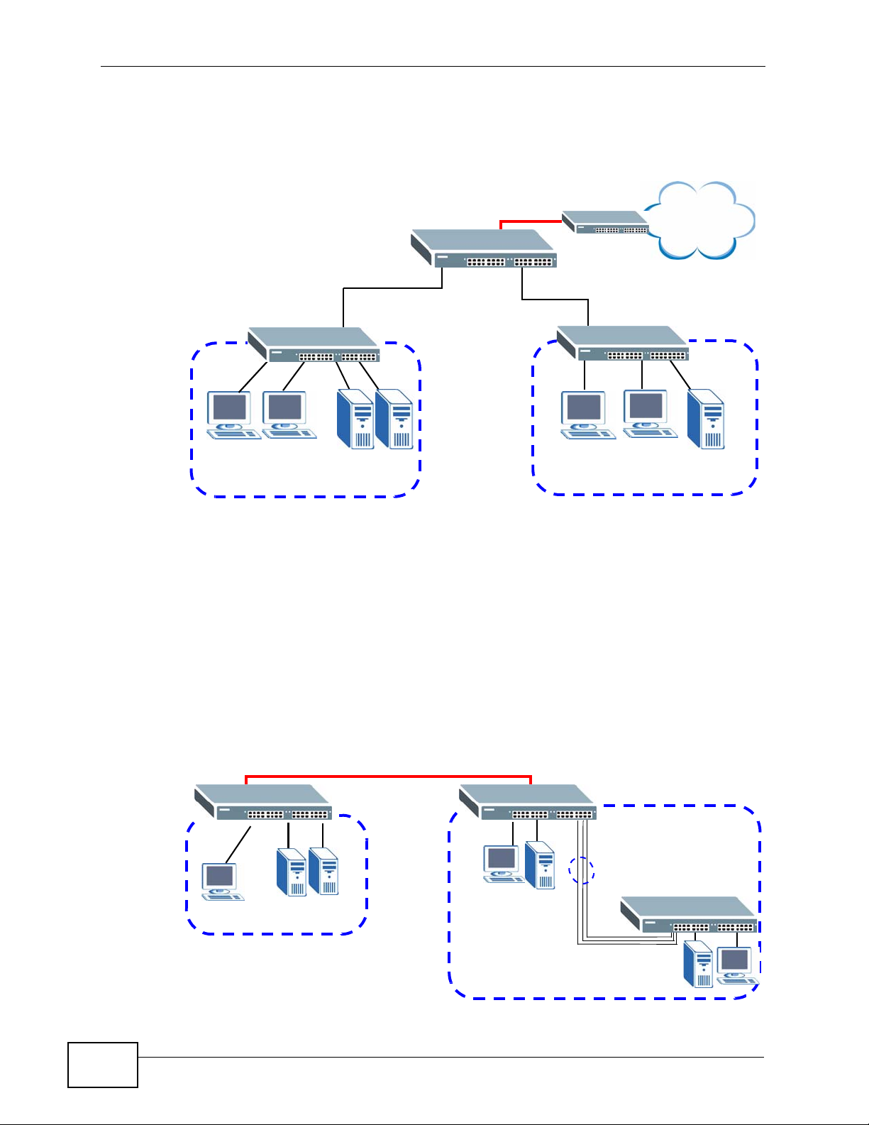
1.1.1 Bridging Example
In this example the Switch connects different company departments (RD and
Sales) to the corporate backbone. It can alleviate bandwidth contention and
eliminate server and network bottlenecks. All users that need high bandwidth can
connect to high-speed department servers via the Switch. You can provide a
XGS-4728F User’s Guide
25
Chapter 1 Getting to Know Your Switch
super-fast uplink connection by using the optional 10 Gigabit uplink module on the
Switch.
Figure 1 Bridging Application
Backbone
RD
Sales
1.1.2 High Performance Switching Example
The Switch is ideal for connecting two geographically dispersed networks that
need high bandwidth. In the following example, a company uses the optional 10
Gigabit uplink modules to connect the headquarters to a branch office network.
Within the headquarters network, a company can use trunking to group several
physical ports into one logical hig h er-capacity link. Trunking can be used if for
example, it is cheaper to use multiple lower-speed links than to under-utilize a
high-speed, but more costly, single-port link.
Figure 2 High Performance Switching
10 Gbps
Trunk
26
Branch
HQ
XGS-4728F User’s Guide
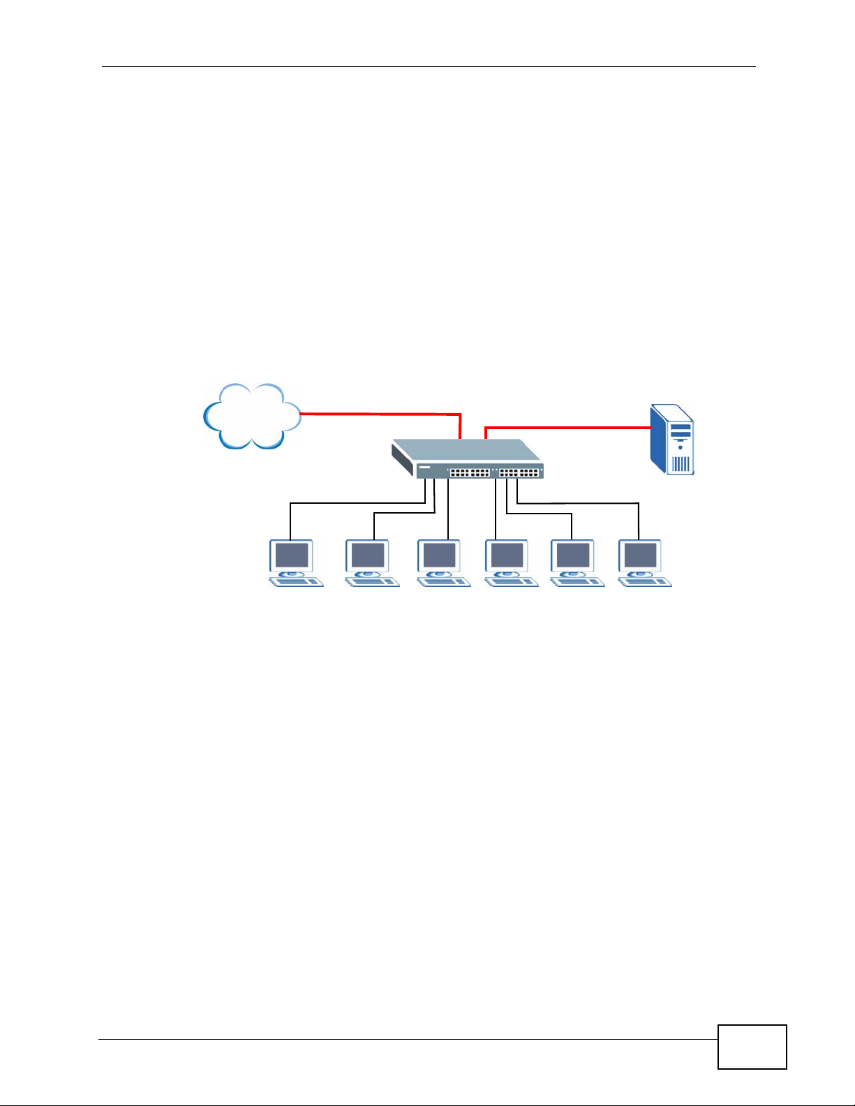
1.1.3 Gigabit Ethernet to the Desktop
The Switch is an ideal solution for small networks which demand high bandwidth
for a group of heavy traffic users. Y ou can conn ect computers an d servers directly
to the Switch’s port or connect other switches to the Switch. Use the optional 10
Gigabit uplink module to provide high speed access to a data server and the
Internet. The uplink module supports a fiber-optic connection which alleviates the
distance limitations of copper cabling.
In this example, all computers can share high-speed applications on the server
and access the Internet. To expand the network, simply add more networking
devices such as switches, routers, computers, print servers and so on.
Figure 3 Gigabit to the Desktop
Internet
Chapter 1 Getting to Know Your Switch
1.1.4 IEEE 802.1Q VLAN Application Example
A VLAN (Virtual Local Area Network) allows a physical network to be partitioned
into multiple logical networks. Stations on a logical network belong to one or more
groups. With VLAN, a station cannot directly talk to or hear from stations that are
not in the same group(s) unless such traffic first goes through a router.
For more information on VLANs, refer to Chapter 9 on page 95.
1.1.4.1 Tag-based VLAN Example
Ports in the same VLAN group share the same frame broadcast domain, thus
increasing network performance by reducing broadcast traffic. VLAN groups can
be modified at any time by adding, moving or changing ports without any recabling.
XGS-4728F User’s Guide
27
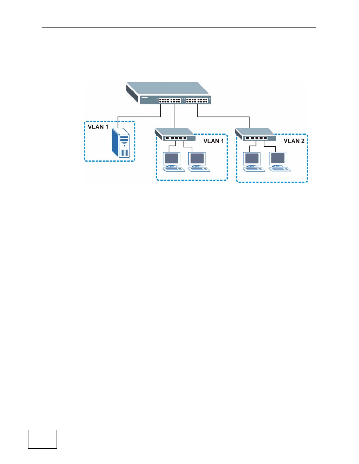
Chapter 1 Getting to Know Your Switch
Shared resources such as a server can be used by all ports in the same VLAN as
the server. In the following figure only ports that need access to the server need
to be part of VLAN 1. Ports can belong to other VLAN groups too.
Figure 4 Shared Server Using VLAN Example
1.2 Ways to Manage the Switch
Use any of the following methods to manage the Switch.
• Web Co nfigurator. This is recommended for ev eryday management of the S witch
using a (supported) web browser. See Chapter 4 on page 45.
• Command Line Interface. Line commands offer an alternative to the Web
Configurator and may be necessary to configure advanced features. See the CLI
Reference Guide.
• FTP. Use File Transfer Protocol for firmware upgrades and configuration backup/
restore. See Section 39.8 on page 333.
• SNMP. The device can be monitored and/or managed by an SNMP manager. See
Section 40.3 on page 338.
1.3 Good Habits for Managing the Switch
Do the following things regularly to make the Switch more secure and to manage
the Switch more effectively.
28
• Change the password. Use a password that’s not easy to guess and that consists
of different types of characters, such as numbers and letters.
• Write down the password and put it in a safe place.
XGS-4728F User’s Guide

Chapter 1 Getting to Know Your Switch
• Back up the configuration (and make sure you know how to restore it).
Restoring an earlier working configuration may be useful if the device becomes
unstable or even crashes. If you forget y our password, you will hav e to reset the
Switch to its factory default settings. If you backed up an earlier configuration
file, you would not have to totally re-configure the Switch. You could simply
restore your last configuration.
XGS-4728F User’s Guide
29

Chapter 1 Getting to Know Your Switch
30
XGS-4728F User’s Guide
 Loading...