

Page 1

P-870HN-51D
802.11n Wireless VDSL2 4-port Gateway
Default Login Details
IP Address https://192.168.1.1
User Name admin
Password 1234
Firmware Version 1.01
Edition 1, 07/2010
www.zyxel.com
www.zyxel.com
Copyright © 2010
ZyXEL Communications Corporation
Page 2

Page 3
About This User's Guide
About This User's Guide
Intended Audience
This manual is intended for people who want to configure the P-870HN-51D using
the web configurator.
Related Documentation
•Quick Start Guide
The Quick Start Guide is designed to help you get up and running right away. It
contains information on setting up your network and configuring for Internet
access.
• Support Disc
Refer to the included CD for support documents.
Documentation Feedback
Send your comments, questions or suggestions to: techwriters@zyxel.com.tw
Thank you!
The Technical Writing Team, ZyXEL Communications Corp.,
6 Innovation Road II, Science-Based Industrial Park, Hsinchu, 30099, Taiwan.
Need More Help?
More help is available at www.zyx el.com.
P-870HN-51D User’s Guide
3
Page 4

About This User's Guide
• Download Library
Search for the latest product updates and documentation from this link. Read
the Tech Doc Overview to find out how to efficiently use the User Guide, Quick
Start Guide and Command Line Interface Reference Guide in order to better
understand how to use your product.
• Knowledge Base
If you have a specific question about your product, the answer may be here.
This is a collection of answers to previously asked questions about ZyXEL
products.
•Forum
This contains discussions on ZyXEL prod ucts. Learn from others who use ZyXEL
products and share your experiences as well.
Customer Support
Should problems arise that cannot be solved by the methods listed above, you
should conta ct your vendor. If you cannot contact your vendor, then contact a
ZyXEL office for the region in which you bought the device.
See http://www.zyxel.com/web/contact_us.php for contact information. Please
have the following informatio n ready when you contact an office.
• Product model and serial number.
•Warranty Information.
• Date that you received your device.
• Brief description of the problem and the steps you took to solve it.
4
P-870HN-51D User’s Guide
Page 5

Document Conventions
Document Conventions
Warnings and Notes
These are how warnings and notes are shown in this User’s Guide.
Warnings tell you about things that could harm you or your device.
Note: Notes tell you other important information (for example, other things you may
need to configure or helpful tips) or recommendations.
Syntax Conventions
• The P-2812HNU-51c may be referred to as the “P-870HN-51D”, the “device”,
the “system” or the “product” in this User’s Guide.
• Product labels, screen names, field labels and field choices are all in bold font.
• A key stroke is denoted by square brackets and uppercase text, for example,
[ENTER] means the “enter” or “return” key on you r keyboard.
• “Enter” means for you to type one or more characters and then press the
[ENTER] key. “Select” or “choose” means for you to use one of the predefined
choices.
• A right angle bracket ( > ) within a screen name denotes a mouse click. For
example, Maintenance > Log > Log Setting means you first click
Maintenance in the navigation panel, then the Log sub menu and finally the
Log Setting tab to get to that screen.
• Units of measurement may denote the “metric” value or the “scientific” value.
For example, “k” for kilo may denote “1000” or “1024”, “M” for mega may
denote “1000000” or “1048576” and so on.
• “e.g.,” is a shorthand for “for instance”, and “i.e.,” means “that is” or “in other
words”.
P-870HN-51D User’s Guide
5
Page 6
Document Conventions
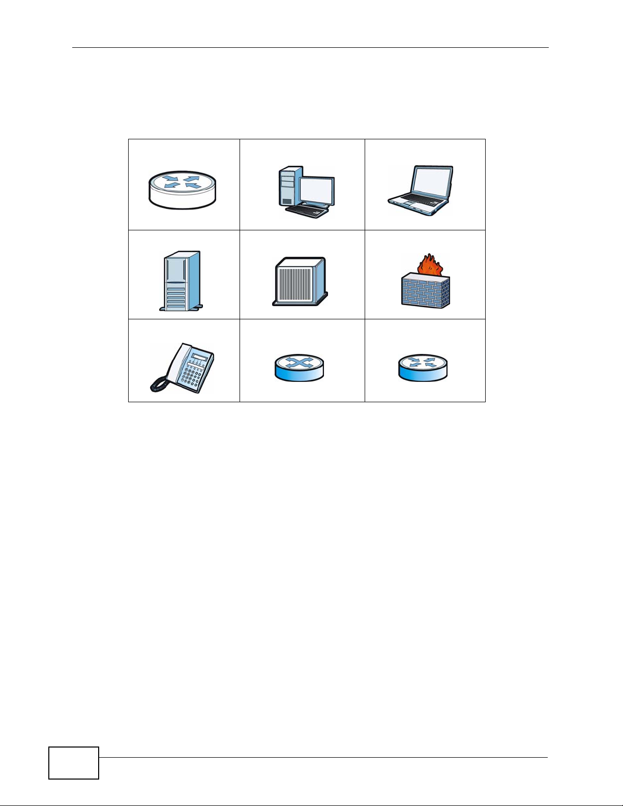
Icons Used in Figures
Figures in this User’s Guide may use the following generic icons. The P-870HN51D icon is not an exact representation of your device.
P-870HN-51D Computer Notebook computer
Server DSLAM Firewall
Telephone Switch Router
6
P-870HN-51D User’s Guide
Page 7

Safety Warnings
Safety Warnings
• Do NOT use this product near water, for example, in a wet basement or near a swimming
pool.
• Do NOT expose your device to dampness, dust or corrosive liquids.
• Do NOT store things on the device.
• Do NOT install, use, or service this device during a thunderstorm. There is a remote risk
of electric shock from lightning.
• Connect ONLY suitable accessories to the device.
• Do NOT open the device or unit. Opening or removing covers can expose you to
dangerous high voltage points or other risks. ONLY qualified service personnel should
service or disassemble this device. Please contact your vendor for further information.
• Make sure to connect the cables to the correct ports.
• Place connecting cables carefully so that no one will step on them or stumble over them.
• Always disconnect all cables from this device before servicing or disassembling.
• Use ONLY an appropriate power adaptor or cord for your device.
• Connect the power adaptor or cord to the right supply voltage (for example, 110V AC in
North America or 230V AC in Europe).
• Do NOT allow anything to rest on the power adaptor or cord and do NOT place the
product where anyone can walk on the power adaptor or cord.
• Do NOT use the device if the power adaptor or cord is damaged as it might cause
electrocution.
• If the power adaptor or cord is damaged, remove it from the device and the power
source.
• Do NOT attempt to repair the power adaptor or cord. Contact your local vendor to order a
new one.
• Do not use the device outside, and make sure all the connections are indoors. There is a
remote risk of electric shock from lightning.
• Do NOT obstruct the device ventilation slots, as insufficient airflow may harm your
device.
• Use only No. 26 AWG (American Wire Gauge) or larger telecommunication line cord.
• Antenna Warning! This device meets ETSI and FCC certification requirements when using
the included antenna(s). Only use the included antenna(s).
• If you wall mount your device, make sure that no electrical lines, gas or water pipes will
be damaged.
Your product is marked with this symbol, which is known as the WEEE mark. WEEE
stands for Waste Electronics and Electrical Equipment. It means that used electrical
and electronic products should not be mixed with general waste. Used electrical and
electronic equipment should be treated separately.
P-870HN-51D User’s Guide
7
Page 8

Safety Warnings
8
P-870HN-51D User’s Guide
Page 9

Contents Overview
Contents Overview
User’s Guide ........................................................................................................ ...................19
Introducing the P-870HN-51D ...................................................................................................21
Tutorials ..................................................................................................................................... 27
Introducing the Web Configurator .............................................................................................. 47
Technical Reference ..............................................................................................................53
Status Screens .......................................................................................................................... 55
WAN Setup ...................................................................... ... ... .... ... ... .......................................... 69
LAN Setup ................................................................................................................................. 91
Wireless LAN ............................ ... .... ... ............................................. ... ... .... ... ... .......................... 99
Network Address Translation (NAT) ........................................................................................ 129
Firewall .................................................................................................................................... 141
Certificate ................................................................................................................................ 147
Static Route ............................................................................................................................. 159
Policy Forwarding .................................................................................................................... 163
RIP ............................... .................... ................... ................... .................... ..............................167
Quality of Service (QoS) ........................... ... .... ... ... ... .... ... ... ... .... ... ... ........................................ 169
Dynamic DNS Setup ................................................................................................................ 189
Remote Management ..............................................................................................................191
Universal Plug-and-Play (UPnP) ............................................................................................. 197
Parental Control .......................................................................................................................209
Interface Group ........................................................................................................................213
System Settings ........... ............................................. .... ... ... ... .... .............................................. 219
Logs ........................................................................................................................................ 223
Tools ........................................................................................................................................ 227
Diagnostic .................................... ....................................................... ..................................... 235
Troubleshooting ..................................................... .................................................................. 239
Product Specifications ............................................................................................................. 247
P-870HN-51D User’s Guide
9
Page 10

Contents Overview
10
P-870HN-51D User’s Guide
Page 11

Table of Contents
Table of Contents
About This User's Guide..........................................................................................................3
Document Conventions............................................................................................................5
Safety Warnings ........................................................................................................................7
Contents Overview ...................................................................................................................9
Table of Contents....................................................................................................................11
Part I: User’s Guide................................................................................ 19
Chapter 1
Introducing the P-870HN-51D................................................................................................21
1.1 Overview ............. ............................................. ... .... ... ... ... .................................................... 21
1.2 P-870HN-51D for Internet Access ...................................................................................... 21
1.3 Ways to Manage the P-870HN-51D .......................... ... ... .... ... ............................................. 22
1.4 Good Habits for Managing the P-870HN-51D ..................................................................... 22
1.5 LEDs (Lights) ......................... .... ... ............................................. ... ... .... ... ... .......................... 23
1.6 The RESET Button ............................. ... .... ... ... ... .... ... ............................................. ... ... ....... 25
1.6.1 Using the Reset Button ............. ... .... ... ... ... .... ... ... ............................................. ... .... ... 25
1.7 The WPS Button .............................. ... ... .... ... ... ... .... ... ... ............................................. ... ....... 25
1.7.1 Turn the Wireless LAN Off or On ............................................................................... 25
1.7.2 Activate WPS ......... ... ............................................. .... ... .............................................25
Chapter 2
Tutorials...................................................................................................................................27
2.1 Overview ............. ............................................. ... .... ... ... ... .................................................... 27
2.2 How to Set up a Wireless Network ...................................................................................... 27
2.2.1 Example Parameters ........................... ... ... .... ... ... ... .... ... ............................................. 27
2.2.2 Configuring the AP ....... .... ... ... ... ... .............................................. ... ... ... .... ... ... ... .......... 28
2.2.3 Configuring the Wireless Client .................................................................................. 30
2.3 Configuring the MAC Address Filter .................................................................................... 36
2.4 Setting Up NAT Port Forwarding ......................................................................................... 37
2.4.1 Port Forwarding ......................... ... .... ............................................. ... ... .... ... ... ... ... .... ...37
2.5 Access the P-870HN-51D Using DDNS .............................................................................. 38
2.5.1 Registering a DDNS Account on www.dyndns.org .................................................... 39
2.5.2 Configuring DDNS on Your P-870HN-51D ................................................................. 39
P-870HN-51D User’s Guide
11
Page 12

Table of Contents
2.5.3 Testing the DDNS Setting ................................... ... .... ............................................. ... 40
2.6 Configuring Static Route for Routing to Another Network ................................................... 40
2.7 Configuring QoS Queue and Class Setup ........................................................................... 43
Chapter 3
Introducing the Web Configurator ........................................................................................47
3.1 Web Configurator Overview ................................................................................................. 47
3.1.1 Accessing the Web Configurator ................................................................................ 47
3.2 Web Configurator Main Screen ........................................................................................... 48
3.2.1 Navigation Panel ....... ... .... ... ... ... ... .... ... ....................................................................... 49
3.2.2 Main Window .......................... ... ............................................. .... ... ... ... .... ... ................51
3.2.3 Status Bar ............................................... ... .............................................. ... ................ 51
Part II: Technical Reference.................................................................. 53
Chapter 4
Status Screens........................................................................................................................55
4.1 Overview ............. ............................................. ... .... ... ... ... .................................................... 55
4.2 Status Screen .................................. ... ............................................. .... ... ... ... .... ................... 55
4.2.1 WAN Service Statistics ............................................................................................... 58
4.2.2 Route Info ..................... .... ... ... ... ... .... ............................................. ... ... .... ... ... .............60
4.2.3 WLAN Station List ..................................... .... ............................................. ... ... ... .......61
4.2.4 VDSL Statistics ................................................. ... ... .... ... ... ... ... .................................... 62
4.2.5 LAN Statistics ............................ ... .... ... ... ............................................. .... ... ... .............66
4.2.6 Client List ............................................................................................ .... ... ... .............66
Chapter 5
WAN Setup...............................................................................................................................69
5.1 Overview ............. ............................................. ... .... ... ... ... .................................................... 69
5.1.1 What Yo u Can Do in this Chapter .............................................................................. 69
5.2 What You Need to Know ..... ... .... ... ... ............................................. ... .... ... ... ... .... ... ... ... ..........70
5.3 Before You Begin ................... .... ............................................. ... ... ... .... ... ... ... .... ... ................71
5.4 The Layer 2 Interface Screen .............................................................................................. 71
5.4.1 Layer 2 Interface Configuration ........................................ ... ... .................................... 72
5.5 The Internet Connection Screen .......................................................................................... 73
5.5.1 WAN Connection Configuration ................................................................................. 74
5.6 Technical Reference ..................... ... ... ... .... ... ... ... .... ... ............................................. ... ... ....... 84
Chapter 6
LAN Setup................................................................................................................................91
6.1 Overview ............. ............................................. ... .... ... ... ... .................................................... 91
12
P-870HN-51D User’s Guide
Page 13

Table of Contents
6.1.1 What Yo u Can Do in this Chapter .............................................................................. 91
6.2 What You Need To Know ....... .... ... ... ... ... .... ... ... ............................................. .... ... ... ... ... .... ... 92
6.3 The LAN IP Screen ..............................................................................................................93
6.4 Technical Reference ..................... ... ... ... .... ... ... ... .... ... ............................................. ... ... ....... 95
Chapter 7
Wireless LAN...........................................................................................................................99
7.1 Overview ............. ............................................. ... .... ... ... ... .................................................... 99
7.1.1 What Yo u Can Do in this Chapter .............................................................................. 99
7.2 What You Need to Know ..... ... .... ... ... ............................................. ... .... ... ... ... .... ... ... ... ........100
7.3 Before You Begin ................... .... ............................................. ... ... ... .... ... ... ... .... ... ..............102
7.4 The General Screen ......................................................................................................... 102
7.4.1 No Security .......................... ... ............................................. ... .... ... ... ... .....................104
7.4.2 WEP Encryption ..... ... ... .............................................. ... ... ... ... .... .............................. 106
7.4.3 WPA(2)-PSK ............................................................................................................ 107
7.4.4 WPA(2) Authentication .............................. .... ... ... ... .... ... ... ... ..................................... 108
7.4.5 MAC Filter ............................................................................................................110
7.4.6 Adding a New MAC Filtering Rule ........................................................................111
7.5 The More AP Screen .........................................................................................................112
7.5.1 More AP Edit .............................................................................................................113
7.6 The WPS Screen ............................... ... .... ... ... ............................................. .... ... ... ... ... ......113
7.7 The WPS Station Screen ...................................................................................................115
7.8 The Advanced Setup Screen .............................................................................................116
7.9 Technical Reference ..................... ... ... ... .... ... ... ... .... ... ............................................. ... ... ......117
7.9.1 Wireless Network Overview ...... ... .............................................. ... ... ... .... ... ... ... ... .... ..118
7.9.2 Additional Wireless Terms .........................................................................................119
7.9.3 Wireless Security Overview ......................................................................................119
7.9.4 WiFi Protected Setup ............................................................................................... 121
Chapter 8
Network Address Translation (NAT)....................................................................................129
8.1 Overview ............... ............................................. .... ... ... ... .... .............................................. 129
8.1.1 What Yo u Can Do in this Chapter ............................................................................ 129
8.2 What You Need to Know ..... ... .... ... ... ............................................. ... .... ... ... ... .... ... ... ... ........129
8.3 The Port Forwarding Screen ............................................................................................. 130
8.3.1 The Port Forwarding Edit Screen ............................................................................ 132
8.4 The Trigger Port Screen ..................................... .... ... ... ... .... ... ... ... ... .... ... ...........................133
8.4.1 Trigger Port Configuration ....................................................................................... 136
8.5 The DMZ Host Screen ....................................................................................................... 137
8.6 The ALG Screen ................................ ... .... ... ... ... .... ... ... ... ............................................. ..... 138
8.7 Technical Reference ..................... ... ... ... .... ... ... ... .... ... ............................................. ... ... ..... 138
Chapter 9
Firewall...................................................................................................................................141
P-870HN-51D User’s Guide
13
Page 14

Table of Contents
9.1 Overview ............... ............................................. .... ... ... ... .... .............................................. 141
9.1.1 What Yo u Can Do in this Chapter ............................................................................ 141
9.2 What You Need to Know ..... ... .... ... ... ............................................. ... .... ... ... ... .... ... ... ... ........141
9.3 The Firewall Screen ...........................................................................................................142
9.3.1 Creating Incoming Firewall Rules .................................................. ... .... ... ... ... ... .... . 144
Chapter 10
Certificate ..............................................................................................................................147
10.1 Overview .......................................................................................................................... 147
10.1.1 What You Can Do in this Chapter .......................................................................... 147
10.2 What You Need to Know .................................................................................................. 147
10.3 The Local Certificates Screen ......................................................................................... 148
10.3.1 Create Certificate Request .................................................................................... 149
10.3.2 Import Certificate . ... ... .... ................................................ ... ..................................... 150
10.3.3 Certificate Details .................................................................................................. 152
10.3.4 Load Signed Certificate ..........................................................................................153
10.4 The Trusted CA Screen .................................... ............................................................... 154
10.4.1 View Trusted CA Certificate ...................................................................................156
10.4.2 Import Trusted CA Certificate ................................................................................. 157
Chapter 11
Static Route...........................................................................................................................159
11.1 Overview .......................................................................................................................159
11.1.1 What You Can Do in this Chapter ......................................... .... .............................. 159
11.2 The Static Route Screen ..................................................................................................160
11.2.1 Static Route Edit ................................................................................................... 161
Chapter 12
Policy Forwarding.................................................................................................................163
12.1 Overview ....................................................................................................................... 163
12.1.1 What You Can Do in this Chapter .......................................................................... 163
12.2 The Static Route Screen .................................................................................................. 163
12.2.1 Policy Forwarding Setup ...................................................................................... 164
Chapter 13
RIP..........................................................................................................................................167
13.1 Overview ....................................................................................................................... 167
13.1.1 What You Can Do in this Chapter .......................................................................... 167
13.2 The RIP Screen ... ... .... ... ... ... .... ................................................ ........................................ 167
Chapter 14
Quality of Service (QoS).......................................................................................................169
14.1 Overview ......................................................................................................................... 169
14
P-870HN-51D User’s Guide
Page 15

Table of Contents
14.1.1 What You Can Do in this Chapter .......................................................................... 169
14.2 What You Need to Know .................................................................................................. 170
14.3 The Quality of Service General Screen .......................................................................... 170
14.4 The Queue Setup Screen ................................................................................................ 172
14.4.1 Adding a QoS Queue ............................................................................................ 173
14.5 The Class Setup Screen ................................................................................................ 174
14.5.1 QoS Class Edit ...................................................................................................... 176
14.6 The Policer Setup Screen ............................................................................................ 180
14.6.1 Policer Setup Add/Edit ........................................................................................... 181
14.7 The QoS Monitor Screen ................................................................................................ 183
14.8 Technical Reference ........................................................................................................ 184
14.8.1 Automatic Priority Queue Assignment ................................................................... 185
14.8.2 Traffic Policing Meter Types .............................. ... ............................................. .... . 186
Chapter 15
Dynamic DNS Setup .............................................................................................................189
15.1 Overview ......................................................................................................................... 189
15.1.1 What You Can Do in this Chapter .......................................................................... 189
15.2 What You Need To Know ................................................................................................. 189
15.3 The Dynamic DNS Screen ................................................ ... ... ... ... .... ... ... ... .... ... ... ........... 190
Chapter 16
Remote Management............................................................................................................191
16.1 Overview .......................................................................................................................... 191
16.1.1 What You Can Do in this Chapter .......................................................................... 191
16.2 The TR-069 Screen .........................................................................................................191
16.3 The TR-064 Screen .........................................................................................................193
16.4 The Service Control Screen ............................................................................................ 194
16.5 The IP Address Screen ................................................................................................... 195
16.5.1 Adding an IP Address ............................................................................................196
Chapter 17
Universal Plug-and-Play (UPnP)..........................................................................................197
17.1 Overview ......................................................................................................................... 197
17.1.1 What You Can Do in this Chapter .......................................................................... 197
17.2 What You Need to Know .................................................................................................. 197
17.3 The UPnP Screen ............................................................................................................198
17.4 Installing UPnP in Windows Example .............................................................................. 199
17.5 Using UPnP in Windows XP Example ............................................................................. 202
Chapter 18
Parental Control....................................................................................................................209
18.1 Overview .......................................................................................................................... 209
P-870HN-51D User’s Guide
15
Page 16

Table of Contents
18.1.1 What You Can Do in this Chapter .......................................................................... 209
18.2 The Time Restriction Screen ........................................................................................... 209
18.2.1 Adding a Schedule ................................................................................................. 210
18.3 The URL Filter Screen ......................................................................................................211
18.3.1 Adding URL Filter ................................................................................................... 212
Chapter 19
Interface Group.....................................................................................................................213
19.1 Overview .......................................................................................................................... 213
19.1.1 What You Can Do in this Chapter .......................................................................... 213
19.2 The Interface Group Screen ............................................................................................ 213
19.2.1 Interface Group Configuration ................................................................................215
19.2.2 Interface Grouping Criteria .....................................................................................216
Chapter 20
System Settings....................................................................................................................219
20.1 Overview .......................................................................................................................... 219
20.1.1 What You Can Do in this Chapter .......................................................................... 219
20.2 The General Screen ........................................................................................................219
20.3 The Time Setting Screen ................................................................................................ 220
Chapter 21
Logs ......................................................................................................................................223
21.1 Overview ......................................................................................................................... 223
21.1.1 What You Can Do in this Chapter .......................................................................... 223
21.2 The View Log Screen ...................................................................................................... 223
21.3 The Log Settings Screen ..... .... ... ... ... ... ............................................................................ 224
Chapter 22
Tools.......................................................................................................................................227
22.1 Overview .......................................................................................................................... 227
22.1.1 What You Can Do in this Chapter .......................................................................... 227
22.2 The Firmware Screen ...................................................................................................... 228
22.3 The Configuration Screen ................................................................................................ 230
22.4 The Restart Screen .........................................................................................................232
Chapter 23
Diagnostic..............................................................................................................................235
23.1 Overview .......................................................................................................................... 235
23.1.1 What You Can Do in this Chapter .......................................................................... 235
23.2 What You Need to Know .................................................................................................. 235
23.3 The General Diagnostic Screen ...................................................................................... 236
23.4 The 802.1ag Screen ........................................................................................................237
16
P-870HN-51D User’s Guide
Page 17

Table of Contents
Chapter 24
Troubleshooting....................................................................................................................239
24.1 Power, Hardware Connections, and LEDs ................................. ... .................................. 239
24.2 P-870HN-51D Access and Login ............................................. .......................... .............. 240
24.3 Internet Access ................................................................................................................ 242
24.4 Wireless LAN Troubleshooting ........................................................................................ 244
Chapter 25
Product Specifications.........................................................................................................247
25.1 Hardware Specifications ..................................................................................................247
25.2 Firmware Specifications ...................................................................................................247
Appendix A Network Troubleshooting..................................................................................253
Appendix B Setting Up Your Computer’s IP Address...........................................................269
Appendix C Pop-up Windows, JavaScripts and Java Permissions......................................299
Appendix D IP Addresses and Subnetting...........................................................................309
Appendix E Wireless LANs ..................................................................................................321
Appendix F Common Services.............................................................................................337
Appendix G Open Software Announcements.......................................................................341
Appendix H Legal Information..............................................................................................355
Index.......................................................................................................................................359
P-870HN-51D User’s Guide
17
Page 18

Table of Contents
18
P-870HN-51D User’s Guide
Page 19

PART I
User’s Guide
19
Page 20

20
Page 21

CHAPTER 1
Introducing the P-870HN-51D
1.1 Overview
The P-870HN-51D is a VDSL2 device that allows super-fast, secure Internet
access. It extends the range of your existing wired network without additional
wiring, providing easy network access to mobile users. You can set up a wireless
network with other IEEE 802.11b/g/n compatible devices. A range of services such
as a firewall and content filtering are also available for secure Internet computing.
The P-870HN-51D supports Quality of Service (QoS) to efficiently manage traffic
on your network by giving priority to certain types of traffic and/or to particular
computers.
Please refer to the following description of the product name format.
• “H” denotes an integrated 4-port hu b (swi tch).
• “N” denotes IEEE 802.11n wireless functionality . There is an embedded mini-PCI
module for IEEE 802.11b/g/n wireless LAN connectivity.
Only use firmware for your P-870HN-51D’s specific model. Refer to
the label on the bottom of your P-870HN-51D.
Models ending in “1”, for example P-870HN-51D, denote a device that works over
the analog telephone system, POTS (Plain Old Telephone Service).
See Chapter 25 on page 247 for a full list of features.
1.2 P-870HN-51D for Internet Access
Your P- 870HN-51D provides shared Internet access by connecting the DSL port t o
the DSL or MODEM jack on a splitter or your telephone jack. You can have up to
seven WAN services over one VDSL WAN line.
P-870HN-51D User’s Guide
21
Page 22
Chapter 1 Introducing the P-870HN-51D
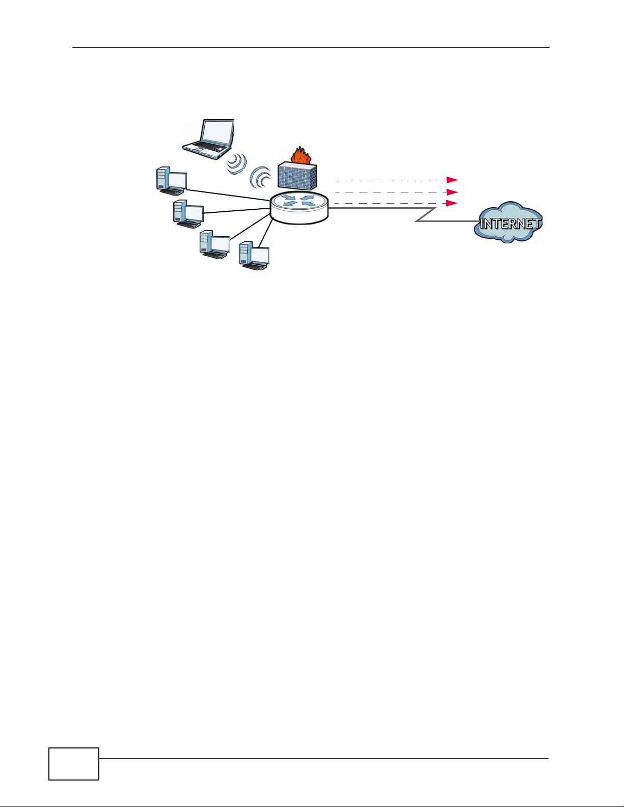
Computers can connect to the P-870HN-51D’s LAN ports (or wirelessly).
Figure 1 P-870HN-51D’s Internet Access Application
WLAN
Bridging
IPoE
PPPoE
VDSL
LAN
You can also configure the firewall on the P-870HN-51D for secure Internet
access. When the firewall is on, all incoming traffic from the Internet to your
network is blocked by default unless it is initiated from your network. This means
that probes from the outside to your network are not allowed, but yo u can safely
browse the Internet and download files.
1.3 Ways to Manage the P-870HN-51D
WAN
Use any of the following methods to manage the P-870HN-51D.
• Web Configurator. This is recommended for everyday management of the P870HN-51D using a (supported) web browser.
• TR-069. This is an auto-configuration server used to remotely configure your
device.
1.4 Good Habits for Managing the P-870HN-51D
Do the following things regularly to make the P-870HN-51D more secure and to
manage the P-870HN-51D more effectively.
• Change the password. Use a password that’s not easy to guess and that consists
of different types of characters, such as numbers and letters.
• Write down the password and put it in a safe place.
22
P-870HN-51D User’s Guide
Page 23
• Back up the configuration (and make sure you know how to restore it).
Restoring an earlier working configuration may be useful if the device becomes
unstable or even crashes. If you forget y our password, you will hav e to reset the
P-870HN-51D to its factory default settings. If you backed up an earlier
configuration file, you would not have to totally re-configure the P-870HN-51D.
You could simply restore your last configuration.
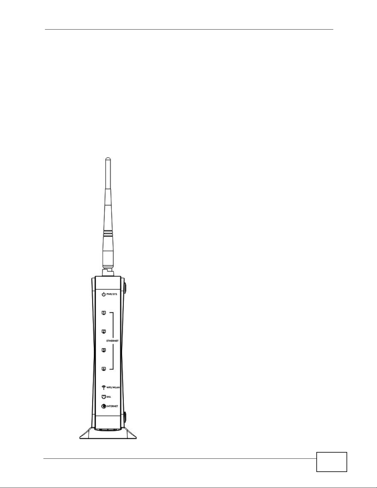
1.5 LEDs (Lights)
The following graphic displays the labels of the LEDs.
Figure 2 LEDs on the Device
Chapter 1 Introducing the P-870HN-51D
P-870HN-51D User’s Guide
23
Page 24

Chapter 1 Introducing the P-870HN-51D
None of the LEDs are on if the P-870HN-51D is not receiving power.
Table 1 LED Descriptions
LED
PWR/SYS Green On The P-870HN-51D is receiving power and ready for use.
ETHERNET
1-4
WLAN/
WPS
DSL Green On The VDSL line is up.
INTERNET Green On The P-870HN-51D has an IP connection but no traffic.
COLO
R
Red On The P-870HN-51D detected an error while self-testing, or
Green On The P-870HN-51D has a successful 10 Mbps Ethernet
Orange On The P-870HN-51D has a successful 100 Mbps Ethernet
Green On The wireless network is activated and is operating in IEEE
Orange Blinking The P-870HN-51D is setting up a WPS connection.
STATUS DESCRIPTION
Blinking The P-870HN-51D is self-testing.
Off The P-870HN-51D is not receiving power.
Blinking The P-870HN-51D is sending or receiving data to/from
Blinking The P-870HN-51D is sending or receiving data to/from
Off The P-870HN-51D does not ha ve an Ethernet connection
Blinking The P-870HN-51D is communicating with other wireless
Off The wireless network is not activated.
Blinking The P-870HN-51D is initializing the VDSL line.
Off The DSL line is down.
there is a device malfunction.
connection with a device on the Local Area Network
(LAN).
the LAN at 10 Mbps.
connection with a device on the Local Area Network
(LAN).
the LAN at 100 Mbps.
with the LAN.
802.11b/g/n mode.
clients at 2 Hz/s.
24
Your device has a WAN IP address (either static or
assigned by a DHCP server), PPP negotiation was
successfully completed (if used) and the DSL connection
is up.
Blinking The P-870HN-51D is sending or receiving IP traffic.
Red On The P-870HN-51D attempted to make an IP connection
but failed. Possible causes are no response from a DHCP
server, no PPPoE response, PPPoE authentication failed.
Off The P-870HN-51D does not have an IP connection.
Refer to the Quick Start Guide for information on hardware connections.
P-870HN-51D User’s Guide
Page 25

1.6 The RESET Button
If you forget your password or cannot access the web configurator, you will need
to use the RESET button at the back of the device to reload the factory-default
configuration file. This means that you will lose all configurations that you had
previously and the password will be reset to “1234”.
1.6.1 Using the Reset Button
1 Make sure the POWER LED is on (not blinking).
2 To set the device back to the factory default settings, press the RESET button for
ten seconds or until the POWER LED begins to blink and then release it. When the
POWER LED begins to blink, the defaults have been restored and the device
restarts.
Chapter 1 Introducing the P-870HN-51D
1.7 The WPS Button
You can use the WPS button on the rear panel of the device to turn the wireless
LAN off or on. Yo u can also use it to activate WPS in order to quickly set up a
wireless network with strong security . Refer to Section 7.9.4 on page 121 for more
information on WPS.
1.7.1 Turn the Wireless LAN Off or On
1 Make sure the POWER LED is on (not blinking).
2 Press the WPS button for one second and release it. The WLAN/WPS LED should
change from on to off or vice versa.
1.7.2 Activate WPS
1 Make sure the POWER LED is on (not blinking).
2 Select Active Wireless LAN and configure the SSID and security settings in the
Network > Wireless LAN screen. Click Apply then.
3 Make sure the WLAN LED is on.
P-870HN-51D User’s Guide
25
Page 26

Chapter 1 Introducing the P-870HN-51D
4 Press the WPS button for more than five seconds and release it. Press the WPS
button on another WPS -enabled device within range of the P-870HN-51D. The
WLAN/WPS LED should flash while the P-870HN-51D sets up a WPS connection
with the wireless device.
Note: You must activate WPS in the P-870HN-51D and in another wireless device
within two minutes of each other. See Section 7.9.4 on page 121 for more
information.
26
P-870HN-51D User’s Guide
Page 27

CHAPTER 2
Tutorials
2.1 Overview
This chapter describes:
• How to Set up a Wireless Network on page 27.
• Configuring the MAC Address Filter on page 36.
• Setting Up NAT Port Forwarding on page 37.
• Access the P-870HN-51D Using DDNS on page 38.
• Configuring Static Route for Routing to Another Network on page 40.
• Configuring QoS Queue and Class Setup on page 43.
Note: The tutorials featured in this chapter require a basic understanding of
connecting to and using the Web Configurator on your P-870HN-51D. For
details, see the included Quick Start Guide. For field descriptions of individual
screens, see the related technical reference in this User's Guide.
2.2 How to Set up a Wireless Network
This tutorial gives you examples of how to set up an access point and wireless
client for wireless communication using the following parameters. The wireless
clients can access the Internet th roug h an AP wirelessly.
2.2.1 Example Parameters
SSID SSID_Example3
Security WPA-PSK
(Pre-Shared Key: ThisismyWPA-PSKpre-sharedkey)
802.11 mode IEEE 802.11b/g/n Mixed
An access point (AP) or wireless router is referred to as “AP” and a computer with
a wireless network card or USB/PCI adapter is referred to as “wireless client” here.
P-870HN-51D User’s Guide
27
Page 28
Chapter 2 Tutorials
We use the P-870HN-51D web screens and M-302 utility screens as an example.
The screens may vary slightly for different models.
2.2.2 Configuring the AP
Follow the steps below to configure the wireless settings on your AP.
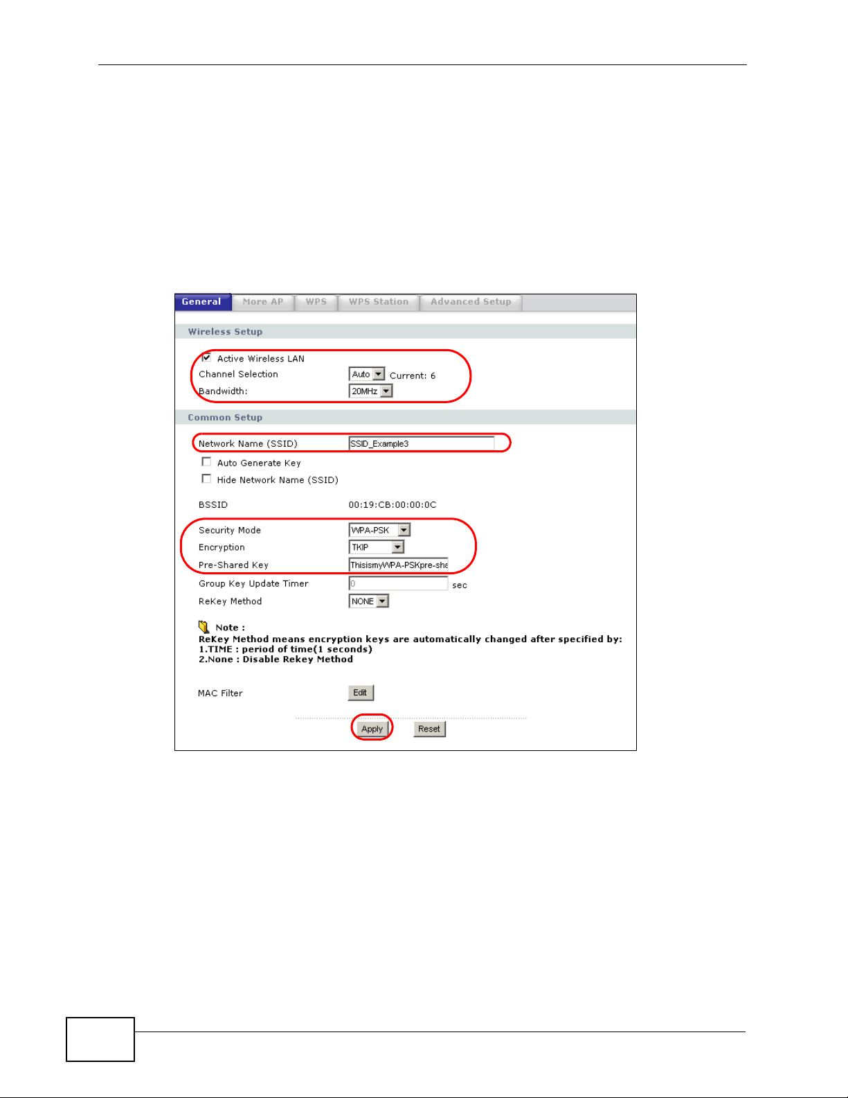
1 Open the Network > Wireless LAN screen in the AP’s web configurator.
Figure 3 AP: Wireless LAN
28
2 Make sure the Active Wireless LAN check box is selected.
3 Enter “SSID_Example3” as the SSID and select Auto to have the P-870HN-51D
automatically determine a channel which is not used by another AP.
4 Set security mode to WPA-PSK and enter “ThisismyWPA-PSKpre-sharedkey” in
the Pre-Shared Key field. Click Apply.
P-870HN-51D User’s Guide
Page 29
Chapter 2 Tutorials
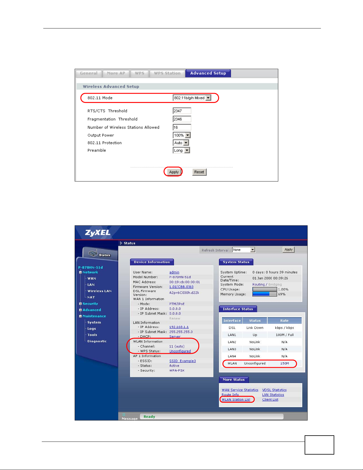
5 Click the Advanced Setup tab and select 802.11b/g/n Mixed in the 802.11
Mode field. Click Apply.
Figure 4 AP: Wireless LAN > Advanced Setup
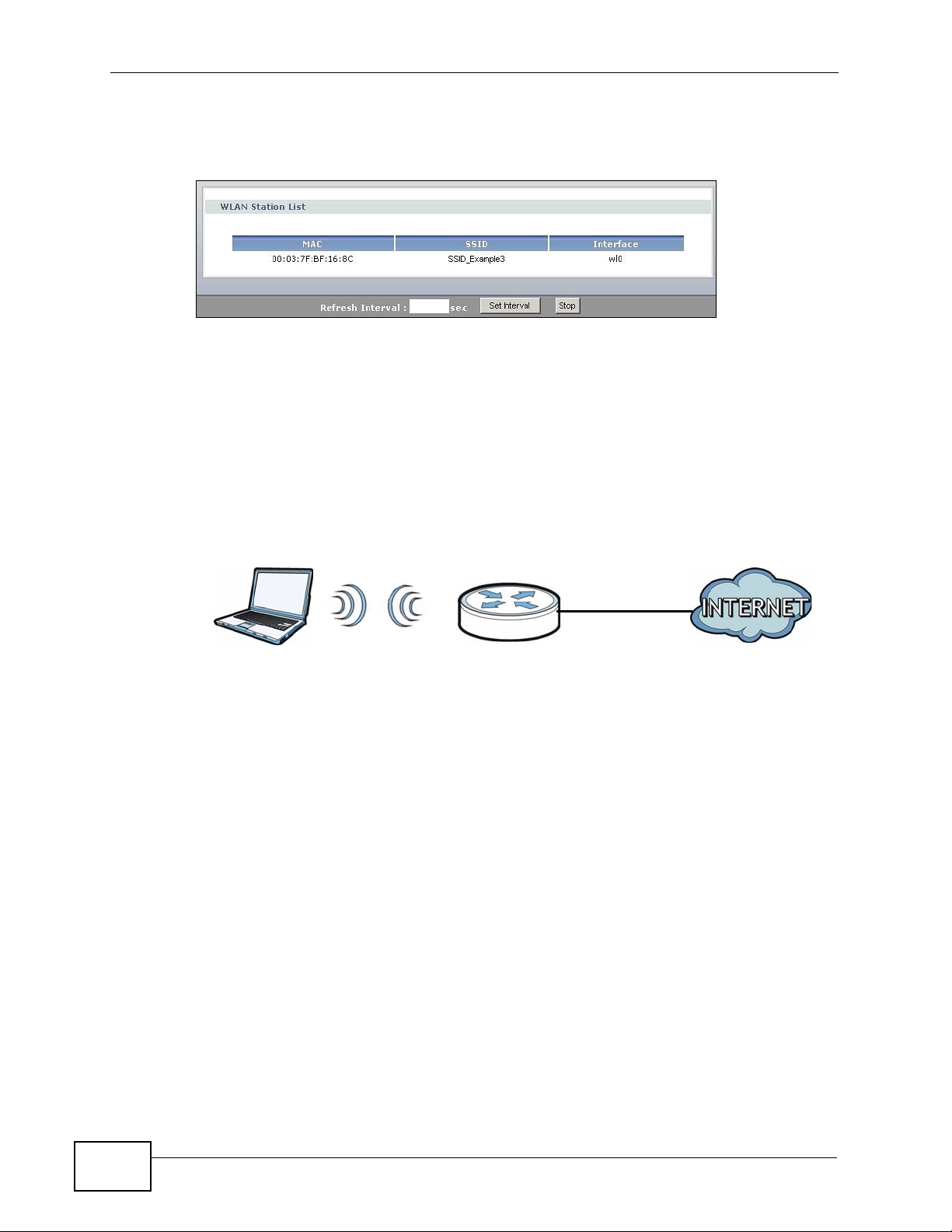
6 Open the Status screen.Verify your wireless and wireless security settings under
Device Information and check if the WLAN connection is up under Interface
Status.
Figure 5 AP: Status
P-870HN-51D User’s Guide
29
Page 30
Chapter 2 Tutorials
7 Click the WLAN Station List hyperlink in the AP’s Status screen. You can see if
any wireless client has connected to the AP.
Figure 6 AP: Status: WLAN Station List
2.2.3 Configuring the Wireless Client
This section describes how to connect the wireless client to a network.
2.2.3.1 Connecting to a Wireless LAN
The following sections show you how to join a wireless network using the ZyXEL
utility, as in the following diagram. The wireless client is labeled C and the access
point is labeled AP.
C
There are three ways to connect the client to an access point.
• Configure nothing and leave the wireless client to automatically scan for and
connect to any available network that has no wireless security configured.
• Manually connect to a network.
• Configure a profile to have the wireless client automatically connect to a specific
network or peer computer.
This example illustrates how to manually connect your wireless cli ent to an access
point (AP) which is configured for WPA-PSK security and connected to the
Internet. Before you connect to the access point, you must know its Service Set
IDentity (SSID) and WPA-PSK pre-shared key. In this example, the SSID is
“SSID_Example3” and the pre-shared key is “ThisismyWPA-PSKpre-sharedkey”.
After you install the ZyXEL utility and then insert the wireless client, follow the
steps below to connect to a network using the Site Survey screen.
AP
30
P-870HN-51D User’s Guide
Page 31

Chapter 2 Tutorials
1 Open the ZyXEL utility and click the Site Survey tab to open the screen shown
next.
Figure 7 ZyXEL Utility: Site Survey
2 The wireless client automatically searches for available wireless networks. Click
Scan if you want to search again. If no entry displays in the Available Network
List, that means there is no wireless network available with i n range. Make su re
the AP or peer computer is turned on or move the wireless client closer to the AP
or peer computer.
3 When you try to conn ec t to an A P with security configured, a window will pop up
prompting you to specify the security settings. Enter the pre-shared k ey and leave
the encryption type at the default setting.
Use the Next button to move on to the next screen. You can use the Back button
at any time to return to the previous screen, or the Exit button to return to the
Site Survey screen.
Figure 8 ZyXEL Utility: Security Settings
P-870HN-51D User’s Guide
31
Page 32

Chapter 2 Tutorials
4 The Conf irm Save window appears. Check your settings and click Save to
continue.
Figure 9 ZyXEL Utility: Confirm Save
5 The ZyXEL utility returns to the Link Info screen while it connects to the wireless
network using your settings. When the wireless link is established, the ZyXEL
utility icon in the system tray turns green and the Link Info screen displays
details of the active connection. Check the network information in the Link Info
screen to verify that you have successfully connected to the selected network. If
the wireless client is not connected to a network, the fields in this screen remain
blank.
Figure 10 ZyXEL Utility: Link Info
6 Open your Internet browser and enter http://www.zyxel.com or the URL of any
other web site in the address bar. If you are able to access the web site, your
wireless connection is successfully configured.
If you cannot access the web site, try changing the encryption type in the
Security Settings screen, check the Troubleshooting section of this User's Guide
or contact your network administrator.
2.2.3.2 Creating and Using a Profile
32
A profile lets you automatically connect to the same wireless network every time
you use the wireless client. You can also configure different profiles for different
P-870HN-51D User’s Guide
Page 33

Chapter 2 Tutorials
networks, for example if you connect a notebook computer to wireless networks at
home and at work.
This example illustrates how to set up a profile and connect the wireless client to
an access point configured for WPA-PSK security. In this example, the SSID is
“SSID_Example3”, the profile name is “PN_Example3” and the pre-shared key is
“ThisismyWPA-PSKpre-sharedkey”. You have chosen the profile name
“PN_Example3”.
1 Open the ZyXEL utility and click the Profile tab to open the screen shown next.
Click Add to configure a new profile.
Figure 11 ZyXEL Utility: Profile
2 The Add New Profile screen appears. The wireless client automatically searches
for available wireless networks, which are displayed in the Scan Info box. Click
on Scan if you want to search again. You can also configure your profile for a
wireless network that is not in the list.
Figure 12 ZyXEL Utility: Add New Profile
3 Give the profile a descriptive name (of up to 32 printable ASCII characters). Select
Infrastructure and either manually enter or select the AP's SSID in the Scan
Info table and click Select.
P-870HN-51D User’s Guide
33
Page 34

Chapter 2 Tutorials
4 Choose the same encryption method as the AP to which you want to connect (In
this example, WPA-PSK).
Figure 13 ZyXEL Utility: Profile Security
5 This screen varies depending on the encryption method you selected in the
previous screen. Enter the pre-shared key and leave the encryption type at the
default setting.
Figure 14 ZyXEL Utility: Profile Encryption
34
6 In the next screen, leave both boxes checked.
Figure 15 Profile: Wireless Protocol Settings.
P-870HN-51D User’s Guide
Page 35

Chapter 2 Tutorials
7 Verify the profile settings in the read-only screen. Click Save to save and go to the
next screen.
Figure 16 Profile: Confirm Save
8 Click Activate Now to use the new profile immediately. Otherwise, click the
Activate Later button.
If you clicked Activate Later, you can select the profile from the list in the Profile
screen and click Connect to activate it.
Note: Only one profile can be activated and used at any given time.
Figure 17 Profile: Activate
9 When you activate the new pro file , the ZyXEL utility returns to t he Link Info
screen while it connects to the AP using your settings. When the wireless link is
established, the ZyXEL utility icon in the system tray turns gr een and the Link
Info screen displays details of the active connection.
10 Open your Internet browser, enter http://www.zyxel.com or the URL of any other
web site in the address bar and press ENTER. If you are able to access the web
site, your new profile is successfully configured.
11 If you cannot access the Internet go back to the Profile screen, select the profile
you are using and click Edit. Check the details you entered previously. Also, refer
to the Troubleshooting section of this User's Guide or contact your network
administrator if necessary.
P-870HN-51D User’s Guide
35
Page 36

Chapter 2 Tutorials
2.3 Configuring the MAC Address Filter
Thomas noticed that his daughter Josephine spends too m uch time surfing the
web and downloading media files. He decided to prevent Josephine from accessing
the Internet so that she can concentrate on preparing for her final exams.
Josephine’s computer connects wirelessly to the Internet through the P-870HN51D. Thomas decides to use the Security > MAC Filter screen to grant wireless
network access to his computer but not to Josephine’s computer.
Thomas
Josephine
1 Click Status > Client List to open the following screen. Lo ok for the MAC ad dress
of Thomas’ computer.
2 Click Security > MAC Filter to open the MAC Filter screen. Select Active. Enter
the MAC address you found in the Client List screen. Click Apply.
36
P-870HN-51D User’s Guide
Page 37

Thomas can also grant access to the computers of other members of his family
and friends. However, Josephine and others not listed in this screen will no longer
be able to access the Internet through the P-870HN-51D.
2.4 Setting Up NAT Port Forwarding
Thomas recently received an Xbox 360 as his birthday gift. His friends in vited him
to play online games with them on Xbox LIVE. In order to communicate and play
with other gamers on Xbox LIVE, Thomas needs to configure the port settings on
his P-870HN-51D.
Xbox 360 requires the following ports to be available in order to operate Xbox
LIVE correctly:
TCP: 53, 80, 3074
UDP: 53, 88, 3074
Chapter 2 Tutorials
Thomas can configure the port settings for Xbox 360.
2.4.1 Port Forwarding
Configure the ports for Xbox 360 by doing the following.
1 Click Network > NAT > Port Forwarding to open the following screen. Select
User define from the Service Name field.
P-870HN-51D User’s Guide
37
Page 38

Chapter 2 Tutorials
2 Configure the screen as follows to open TCP/UDP port 53 for Xbox 360. Click
Apply.
3 Repeat steps 2 and 3 to open the rest of the ports for Xbox 360. Use a different
service name for each port you want to add The port forwarding settings you
configured are listed in the Port Forwarding screen.
Thomas can then connect his Xbox 360 to the Internet and play online games with
his friends.
2.5 Access the P-870HN-51D Using DDNS
If you connect your P-870HN-51D to the Internet and it uses a dynamic WAN IP
address, it is inconvenient for you to manage the device from the Inter net. The P-
38
P-870HN-51D User’s Guide
Page 39

Chapter 2 Tutorials
870HN-51D’s WAN IP address changes dynamically. Dynamic DNS (DDNS) allows
you to access the P-870HN-51D using a domain name.
http://zyxelrouter.dyndns.org
A
w.x.y.z
To use this feature, you have to apply for DDNS service at www.dyndns.org.
This tutorial shows you how to:
• Registering a DDNS Account on www.dyndns.org
• Configuring DDNS on Your P-870HN-51D
• Testing the DDNS Setting
a.b.c.d
Note: If you have a private WAN IP address, then you cannot use DDNS.
2.5.1 Registering a DDNS Account on www.dyndns.org
1 Open a browser and type http://www.dyndns.org.
2 Apply for a user account. This tutorial uses UserName1 and 12345 as the
username and password.
3 Log into www.dyndns.org using your account.
4 Add a new DDNS host name. This tutorial uses the following settings as an
example.
• Hostname: zyxelrouter.dyndns.org
•Service Type: Host with IP address
• IP Address: Enter the WAN IP address that your P-870HN-51D is currently
using. You can find the IP address on the P-870HN-51D’s Web Configurator
Status page.
Then you will need to configure the same account and host name on the P-870HN51D later.
2.5.2 Configuring DDNS on Your P-870HN-51D
1 Log into the P-870HN-51D's advanced mode.
P-870HN-51D User’s Guide
39
Page 40

Chapter 2 Tutorials
2 Configure the following settings in the Advanced > Dynamic DNS screen.
2a Select WWW.DynDNS.ORG for the Service Provider.
2b Type zyxelrouter.dyndns.org in the Host Name field.
2c Select interface for which the DDNS applies.
2d Enter the user name (UserName1) and password (12345).
2e Click Apply.
2.5.3 Testing the DDNS Setting
Now you should be able to access the P-870HN-51D from the Internet. To test
this:
1 Open a web browser on the computer (using the IP address a.b.c.d) that is
connected to the Internet.
2 Type http://zyxelrouter.dyndns.org and press [Enter].
3 The P-870HN-51D’s login page should appear. You can then log into the P-870HN-
51D and manage it.
2.6 Configuring Static Route for Routing to Another Network
40
In order to extend your Intranet and control traffic flowing directions, you may
connect a router to the P-870HN-51D’s LAN. The router may be used to separate
two department networks. This tutorial shows how to configure a static routing
rule for two network routings.
P-870HN-51D User’s Guide
Page 41

Chapter 2 Tutorials
In the following figure, router R is connected to the P-870HN-51D’s LAN. R
connects to two networks, N1 (192.168.1.x/24) and N2 (192.168.10.x/24). If
you want to send traffic from computer A (in N1 network) to com puter B (in N2
network), the traffic is sent to the P-870HN-51D’s WAN default gateway by
default. In this case, B will never receive the traffic.
N1
A
R
N2
B
You need to specify a static routing rule on the P-870HN-51D to specify R as the
router in charge of forwarding traffic to N2. In this case, the P-870HN-51D routes
traffic from A to R and then R routes the traffic to B.
N1
A
R
N2
B
P-870HN-51D User’s Guide
41
Page 42

Chapter 2 Tutorials
This tutorial uses the following example IP settings:
Table 2 IP Settings in this Tutorial
DEVICE / COMPUTER IP ADDRESS
The P-870HN-51D’s WAN 172.16.1.1
The P-870HN-51D’s LAN 192.168.1.1
A 192.168.1.34
R’s N1 192.168.1.253
R’s N2 192.168.10.2
B 192.168.10.33
To configure a static route to route traffic from N1 to N2:
1 Log into the P-870HN-51D’s Web Configurator in advanced mode.
2 Click Advanced > Static Route.
3 Click Add to add a new rule in the Stat ic Route screen.
4 Configure the Static Route Setup screen using the following settings:
4a Type 192.168.10.0 and subnet mask 255.255.255.0 for the destination
(N2).
4b Select the WAN interface to which the rule applies. This example uses the
default WAN interface.
4c Select Gateway Address and type 192.168.1.253 (R’s N1 address) in the
Gateway IP Address field.
4a Click Apply.
42
P-870HN-51D User’s Guide
Page 43

Chapter 2 Tutorials
Now B should be able to receive traffic from A. You may need to additionally
configure B’s firewall settings to allow specific traffic to pass through.
2.7 Configuring QoS Queue and Class Setup
This section contains tutorials on how you can configure the QoS screen.
Let’s say you are a team leader of a small sales branch office. You want to
prioritize e-mail traffic because your task includes sending urgent updates to
clients at least twice every hour. You also upload data files (such as logs and email archives) to the FTP server throughout the day. Your colleagues use the
Internet for research, as well as chat applications for communicating with other
branch offices.
In the following figure, your Internet connection has an upstream transmission
bandwidth of 10,000 kbps. For this exampl e, y ou want to configure QoS so that email traffic gets the highest priority with at least 5,000 kbps. You can do the
following:
• Configure a queue to assign the highest priority queue (7) to e-mail traffic from
the LAN interface, so that e-mail traffic would not get delayed when there is
network congestion.
• Note the IP address (192.168.1.23 for example) and/or MAC address
(AA:FF:AA:FF:AA:FF for example) of your computer and map it to queue 7.
Note: QoS is applied to traffic flowing out of the P-870HN-51D.
Traffic that does not match this class is assigned a priority queue based on the
internal QoS mapping table on the P-870HN-51D.
QoS Example
DSL
10,000 kbps
Your computer
IP=192.168.1.23
and/or
MAC=AA:FF:AA:FF:AA:FF
Email traffic: Highest priority
A colleague’s computer
Other traffic: Automatic classifier
P-870HN-51D User’s Guide
43
Page 44

Chapter 2 Tutorials
1 Click Advanced > QoS > General and check Active. Set your WAN Managed
Upstream Bandwidth to 10,000 kbps (or leave this blank to have the P-870HN-
51D automatically determine this figure).
Tutorial: Advanced > QoS
2 Go to Advanced > QoS > Queue Setup. Click Add to create a new queue. In
the screen that opens, check Active and enter or select the following values:
• Name: E-mail
• Interface: LAN/WLAN
• Priority: 4 (High)
• Weight: 8
• Rate Limit: 5,000 (kbps)
Tutorial: Advanced > QoS > Queue Setup
44
P-870HN-51D User’s Guide
Page 45

Chapter 2 Tutorials
3 Go to Advanced > QoS > Class Setup. Click Add to create a new class. Check
Active and follow the settings as shown in the screen below.
Tutorial: Advanced > QoS > Class Setup
Class Name Give a class name to this traffic, such as E-mail in
To Queue Link this to an item in the Advanced > QoS >
From Interface This is the interface from which the traffic will be
Ether Type Select IP to identify the traffic source by its IP
P-870HN-51D User’s Guide
this example.
Queue Setup screen, which is the E-mail queue
created in this example.
coming from. Select Local.
address or MAC address.
45
Page 46

Chapter 2 Tutorials
MAC Address Type the MAC address of your computer -
IP Address Type the IP address of your computer -
This maps e-mail traffic coming from port 25 to the highest priority, which you
have created in the previous screen (see the IP Protocol field). This also maps
your computer’s IP address and MAC address to the E-mail queue (see the
Source fields).
4 Verify that the queue setup works by checking Advanced > QoS > Monitor. This
shows the bandwidth alloted to e-mail traffic compared to other network traffic.
Tutorial: Advanced > QoS > Monitor
AA:FF:AA:FF:AA:FF. Type the MAC Mask if you
know it.
192.168.1.23. Type the IP Subnet Mask if you
know it.
46
P-870HN-51D User’s Guide
Page 47

CHAPTER 3
Introducing the Web
Configurator
3.1 Web Configurator Overview
The web configurator is an HTML-based management interface that allows easy
device setup and management via Internet browser. Use Internet Explorer 6.0 and
later versions or Mozilla Firefox 3 .6 and later versions. The recommended screen
resolution is 1024 by 768 pixels.
In order to use the web configurator you need to allow:
• Web browser pop -up windows from your device. W eb pop-up blocking is enabl ed
by default in Windows XP SP (Service Pack) 2.
• JavaScripts (enabled by default).
• Java permissions (enabled by default).
See Appendix C on page 299 if you need to make sure these functions are allowed
in Internet Explorer.
3.1.1 Accessing the Web Configurator
1 Make sure your P-870HN-51D hardware is properly connected (refer to the Quick
Start Guide).
2 Launch your web browser.
3 Type "https://192.168.1.1" as the URL.
P-870HN-51D User’s Guide
47
Page 48

Chapter 3 Introducing the Web Configurator
4 A password screen displays. Enter the default admin user name admin and
default admin password 1234. The password displays in non-readable characters.
If you have changed the password, enter your password and click OK. Click
Cancel to revert to the default password in the password field.
Figure 18 Password Screen
3.2 Web Configurator Main Screen
Figure 19 Main Screen
A
48
B
C
P-870HN-51D User’s Guide
Page 49

Chapter 3 Introducing the Web Configurator
As illustrated above, the main screen is divided into these parts:
• A - navigation panel
• B - main window
• C - status bar
3.2.1 Navigation Panel
Use the menu items on the navigation panel to open screens to configure P870HN-51D features. The following tables describe each menu item.
Table 3 Navigation Panel Summary
LINK TAB FUNCTION
Status This screen shows the P-870HN-51D’s general device and network
status information. Use this screen to access the statistics and
client list.
Network
WAN Layer 2
Interface
Internet
Connection
LAN IP Use this screen to configure LAN TCP/IP, DHCP and IP alias
Wireless LAN General Use this screen to configure the wireless LAN settings, WLAN
More AP Use this screen to configure multiple BSSs on the P-870HN-51D.
WPS Use this screen to enable WPS (Wi-Fi Protected Setup) and view
WPS Station Use this screen to use WPS to set up your wireless network.
Advanced
Setup
NAT Port
Forwarding
Use this screen to add or remove a DSL PTM (Packet Transfer
Mode) interface.
Use this screen to configure ISP parameters, WAN IP address
assignment, and other advanced properties.
settings.
authentication/security settings and MAC filtering rules.
the WPS status.
Use this screen to configure the advanced wireless LAN settings.
The NAT screens are available only when you enable NAT in a
WAN connection.
Use this screen to make your local servers visible to the outside
world.
Trigger Port
DMZ Host Use this screen to configure a default server which receives
ALG
Security
Firewall Incoming This screen shows a summary of the IP filtering rules, and allows
Use this screen to change your P-870HN-51D’s port triggering
settings.
packets from ports that are not specified in the Port Forwarding
screen.
Use this screen to allow SIP sessions to pass through the P870HN-51D.
you to add or remove an incoming IP filtering rule that allows
incoming traffic from the WAN.
P-870HN-51D User’s Guide
49
Page 50

Chapter 3 Introducing the Web Configurator
Table 3 Navigation Panel Summary
LINK TAB FUNCTION
Certificate Local
Certificates
Trusted CA Use this screen to view and manage the list of the trusted CAs.
Advanced
Static Route IP Static Route Use this screen to configure IP static routes to tell your device
Policy
Forwarding
RIP Use this screen to configure RIP (Routing Information Protocol)
QoS General Use this screen to enable QoS.
Queue Setup
Class Setup Use this screen to define a classifier.
Policer Setup Use this screen to specify the committed rate and committed
Monitor Use this screen to view QoS packets statistics.
Dynamic DNS This screen allows you to use a static hostname alias for a
Remote
MGMT
UPnP General Use this screen to turn UPnP on or off.
Parental
Control
Interface
Group
Maintenance
System General Use this screen to configure your device’s name, domain name,
Logs View Log Use this screen to view the logs for the level that you selected.
Tools Firmware Use this screen to upload firmware to your device.
TR069 Use this screen to configure the P-870HN-51D to be managed by
TR064 Use this screen to enable management via TR-064 on the LAN.
ServiceControl Use this screen to configure which services/protocols can access
IP Address Use this screen to configure from which IP address(es) users can
Time
Restriction
URL Filter Use this screen to prevent users of your netowrk from viewing
Time Setting Use this screen to change your P-870HN-51D’s time and date.
Log Settings Use this screen to change your P-870HN-51D’s log settings.
Configuration Use this screen to backup and restore your device’s configuration
Restart This screen allows you to reboot the P-870HN-51D without
Use this screen to view a summary list of certificates and manage
certificates and certification requests.
about networks beyond the directly connected remote nodes.
Use this screen to configure policy routing on the P-870HN-51D.
settings.
Use this screen to configure QoS queues.
burst size for incoming packets.
dynamic IP address.
an ACS (Auto Configuration Server).
which P-870HN-51D interface.
manage the P-870HN-51D.
Use this screen to configure the days and times when the
restrictions are enforced.
inappropriate web content.
Use this screen to map a port to a PVC or bridge group.
management inactivity timeout and password.
(settings) or reset the factory default settings.
turning the power off.
50
P-870HN-51D User’s Guide
Page 51

Chapter 3 Introducing the Web Configurator
Table 3 Navigation Panel Summary
LINK TAB FUNCTION
Diagnostic General Use this screen to test the connections to other devices.
802.1ag Use this screen to configure CFM (Connectivity Fault
Management) MD (maintenance domain) and MA (maintenance
association), perform connectivity tests and view test reports.
3.2.2 Main Window
The main window displays information and configuration fields. It is discussed in
the rest of this document.
Right after you log in, the Status screen is displayed. See Chapter 4 on page 55
for more information about the Status screen.
3.2.3 Status Bar
Check the status bar when you click Apply or OK to verify that the configuration
has been updated.
P-870HN-51D User’s Guide
51
Page 52

Chapter 3 Introducing the Web Configurator
52
P-870HN-51D User’s Guide
Page 53

PART II
Technical Reference
53
Page 54

54
Page 55

CHAPTER 4
Status Screens
4.1 Overview
Use the Status screens to look at the current status of the device, system
resources and interfaces (LAN, WAN and WLAN). The Status screen also pro vides
detailed information from DHCP and statistics from traffic.
4.2 Status Screen
Click Status to open this screen.
Figure 20 Status Screen
P-870HN-51D User’s Guide
55
Page 56

Chapter 4 Status Screens
Each field is described in the following table.
Table 4 Status Screen
LABEL DESCRIPTION
Refresh Interval Enter how often you want the P-870HN-51D to update this screen.
Apply Click this to update this screen immediately.
Device
Information
User Name This field displays the P-870HN-51D system name. It is used for
Model
Number
MAC
Address
Firmware
Version
DSL
Firmware
Version
WAN
Information
Mode This is the method of encapsulation used by your ISP.
IP Address This field displays the current IP address of the P-870HN-51D in the
IP Subnet
Mask
LAN
Information
IP Address This field displays the current IP address of the P-870HN-51D in the
IP Subnet
Mask
DHCP This field displays what DHCP services the P-870HN-51D is providing to
identification. Click this to go to the screen where you can change it.
This is the model name of your device.
This is the MAC (Media Access Control) or Ethernet address unique to
your P-870HN-51D.
This field displays the current version of the firmware inside the device.
It also shows the date the firmware version was created. Click this to go
to the screen where you can change it.
This field displays the current version of the device’s DSL modem code.
WAN.
This field displays the current subnet mask in the WAN.
LAN. Click this to go to the screen where you can change it.
This field displays the current subnet mask in the LAN.
the LAN. Choices are:
56
Server - The P-870HN-51D is a DHCP server in the LAN. It assigns IP
addresses to other computers in the LAN.
Relay - The P-870HN-51D acts as a surrogate DHCP server and relays
DHCP requests and responses between the remote server and the
clients.
None - The P-870HN-51D is not providing any DHCP services to the
LAN.
Click this to go to the screen where you can change it.
WLAN
Information
Channel This is the channel number used by the P-870HN-51D now.
P-870HN-51D User’s Guide
Page 57

Chapter 4 Status Screens
Table 4 Status Screen
LABEL DESCRIPTION
WPS Status This field displays the status of WPS (Wi-Fi Protected Setup). Click this
to go to the screen where you can change it.
AP Information
ESSID This is the descriptive name used to identify the P-870HN-51D in this
wireless network. Click this to go to the screen where you can change
it.
Status This shows the current status of the wireless network.
Security This shows the level of wireless security the P-870HN-51D is using in
this wireless network.
System Status
System
Uptime
Current
Date/Time
System
Mode
CPU Usage This field displays what percentage of the P-870HN-51D’s processing
Memory
Usage
Interface Status
Interface This column displays each interface the P-870HN-51D has.
Status This field indicates whether or not the P-870HN-51D is using the
This field displays how long the P-870HN-51D has been running since it
last started up. The P-870HN-51D starts up when you plug it in, when
you restart it (Maintenance > Tools > Restart), or when you reset it
(see Section 1.6 on page 25).
This field displays the current date and time in the P-870HN-51D. You
can change this in Maintenance > System > Time Setting.
This displays whether the P-870HN-51D is functioning as a router or a
bridge.
ability is currently used. When this percentage is close to 100%, the P-
870HN-51D is running at full load, and the throughput is not going to
improve anymore. If you want some applications to have more
throughput, you should turn off other applications (for example, using
QoS; see Chapter 14 on page 169).
This field displays what percentage of the P-870HN-51D’s memory is
currently used. Usually, this percentage should not increase much. If
memory usage does get close to 100%, the P-870HN-51D is probably
becoming unstable, and you should restart the device. See Section 22.4
on page 232, or turn off the device (unplug the power) for a few
seconds.
interface.
P-870HN-51D User’s Guide
For the DSL interface, this field displays LinkDown (line is down) or Up
(line is up or connected).
For the LAN or Ethernet WAN interface, this field displays Up when the
P-870HN-51D is using the interface and NoLink when the line is
disconnected.
For the WLAN interface, it displays Up when WLAN is enabled or
Disabled when WLAN is not active.
57
Page 58

Chapter 4 Status Screens
Table 4 Status Screen
LABEL DESCRIPTION
Rate For the DSL interface, it displays the downstream and upstream
More Status
WAN Service
Statistics
Route Info Click this link to view the internal routing table on the P-870HN-51D.
WLAN
Station List
VDSL
Statistics
LAN
Statistics
Client List Click this link to view current DHCP client information. See Section
transmission rate.
For the LAN or Ethernet WAN interface, this displays the port speed and
duplex setting.
For the WLAN interface, it displays the maximum transmission rate.
Click this link to view packet specific statistics of the WAN
connection(s). See Section 4.2.1 on page 58.
See Section 4.2.2 on page 60.
Click this link to display the MAC address(es) of the wireless stations
that are currently associating with the P-870HN-51D. See Section 4.2.3
on page 61.
Click this to check the VDSL status and detailed performance data.
Click this link to view packet specific statistics on the LAN and WLAN
interfaces. See Section 4.2.5 on page 66.
4.2.6 on page 66.
4.2.1 WAN Service Statistics
Click Status > WLAN Service Statistics to access this screen. Use this screen to
view the WAN statistics.
Figure 21 Status > WAN Service Statistics
58
P-870HN-51D User’s Guide
Page 59

Chapter 4 Status Screens
The following table describes the labels in this screen.
Table 5 Status > WAN Service Statistics
LABEL DESCRIPTION
Interface This shows the name of the WAN interface used by this connection.
A default name ipoa0, pppoa1, atmx (where x starts from 0 and is the
index number of ATM layer-2 interfaces using different VPI and/or VCI
values) or ptm0 indicates the DSL port. The pppx name (where x starts
from 0 and is the index number of PPP connection on the P-870HN-51D)
indicates a PPP connection via any one of the WAN interface. eth4
indicates the Ethernet WAN interface (the physical Ethernet WAN port).
The number after the dot (.) represents the VLAN ID n umber assigned to
traffic sent through this connection. The number after the underscore
(_) represents the index number of connections through the same
interface.
(null) means the entry is not valid.
Description This shows the descriptive name of this connection.
0 and 35 or 0 and 1 are the default VPI and VCI numbers. The last
number represents the index number of connections over the same PVC
or the VLAN ID number assigned to traffic sent through this connection.
(null) means the entry is not valid.
Received
Bytes This indicates the number of bytes received on this interface.
Pkts This indicates the number of transmitted packets on this interface.
Errs This indicates the number of frames with errors received on this
interface.
Drops This indicates the number of received packets dropped on this interface.
Transmitted
Bytes This indicates the number of bytes transmitted on this interface.
Pkts This indicates the number of transmitted packets on this interface.
Errs This indicates the number of frames with errors transmitted on this
interface.
Drops This indicates the number of outgoing packets dropped on this interface.
Refresh
Interval
Set Interval Click this button to apply the new poll interval you entered in the
Stop Click Stop to stop refreshing statistics.
Enter the time interval for refreshing statistics in this field.
Refresh Interval field.
P-870HN-51D User’s Guide
59
Page 60

Chapter 4 Status Screens
4.2.2 Route Info
Routing is based on the destination address only and the P-870HN-51D takes the
shortest path to forward a packet. Click Status > Route Info to access this
screen. Use this screen to view the internal routing table on the P-870HN-51D.
Figure 22 Status > Route Info
The following table describes the labels in this screen.
Table 6 Status > Route Info
LABEL DESCRIPTION
Destination This indicates the destination IP address of this route.
Gateway This indicates the IP address of the gateway that helps forward this route’s
Subnet
Mask
Flag This indicates the route status.
traffic.
This indicates the destination subnet mask of this route.
Up: The route is up.
!(Reject): The route is blocked and will force a route lookup to fail.
Gateway: The route uses a gateway to forward traffic.
Host: The target of the route is a host.
Reinstate: The route is reinstated for dynamic routing.
Dynamic (redirect): The route is dynamically installed by a routing daemon
or redirect
Modified (redirect): The route is modified from a routing daemon or
rederict.
Metric The metric represents the "cost of transmission". A router determines the
best route for transmission by choosing a path with the lowest "cost". The
smaller the number, the lower the "cost".
60
P-870HN-51D User’s Guide
Page 61

Table 6 Status > Route Info (continued)
LABEL DESCRIPTION
Service This indicates the name of the service used to forward the route.
Interface This indicates the name of the interface through which the route is
forwarded.
• br0 indicates the LAN interface.
• ptm0 indicates the VDSL WAN interface using IPoE or in bridge mode.
• pppoa1 indicates the ADSL WAN interface using PPPoA.
• ipoa0 indicates the ADSL WAN interface using IPoA.
• ppp0 indicates the WAN interface using PPPoE.
• eth4 indicates the Ethernet WAN interface using IPoE.
4.2.3 WLAN Station List
Click Status > WLAN Station List to access this screen. Use this screen to view
the wireless stations that are currently associated to the P-870HN-51D.
Figure 23 Status > WLAN Station List
Chapter 4 Status Screens
The following table describes the labels in this screen.
Table 7 Status > WLAN Station List
LABEL DESCRIPTION
MAC This field shows the MAC (Media Access Control) address of an associated
wireless station.
SSID This field shows the SSID to which the wireless station is connected.
Interface This field shows the wireless interface to which the wireless station is
connected.
Refresh
Interval
Set Interval Click this button to apply the new poll interval you entered in the Refresh
Stop Click Stop to stop refreshing statistics.
Enter the time interval for refreshing statistics in this field.
Interval field.
P-870HN-51D User’s Guide
61
Page 62

Chapter 4 Status Screens
4.2.4 VDSL Statistics
Click Status > VDSL Statistics to open the following screen. Use this screen to
check VDSL status and detailed performance data.
Figure 24 Status > VDSL Statistics
62
The following table describes the labels in this screen.
Table 8 Status > VDSL Statistics
LABEL DESCRIPTION
VDSL Training
Status
VDSL Profile This shows the name of the VDSL profile which is applied to the VDSL
Traffic Type This indicates whether the PTM interface is active (PTM Mode) or
This shows whether the DSL port is connected (Showtime); idle (Idle);
not connected; is negotiating a connection with a COE device (G.994
Training); is under loop test (RUN_LD_INIT); or under channel
analysis(G.922 Channel Analysis).
port to which the P-870HN-51D is connected.
inactive (Inactive).
P-870HN-51D User’s Guide
Page 63

Chapter 4 Status Screens
Table 8 Status > VDSL Statistics (continued)
LABEL DESCRIPTION
VDSL Port Details
These are the maximum Upstream and Downstream transfer rates for the ports that
belong to this profile. Upstream traffic refers to traffic from the P-870HN-51D to the
Central Organization Equipment (COE). Downstream traffic refers to traffic from the COE
to the P-870HN-51D.
Line Rate This indica tes the maximum upstream/downstream net data rate
currently attainable on this line.
Actual Net Line
Rate
Trellis Coding Trellis coding is a modulation scheme which allows highly efficient
SNR Margin This indicates the upstream/downstream SNR margin.
Actual Delay This indicates the actual upstream/downstream transmission delay (in
Transmit
Power
Receive Power This indicates the upstream/downstream receiving power of the line.
Actual INP This indicates the actual impulse noise protection (INP).
Total
Attenuation
Attainable Net
Data Rate
VDSL Band
Status
Line
Attenuation
Signal
Attenuation
SNR Margin This indicates the signal to noise ratio for each upstream and
Transmit
Power
Since Link time T his indicates VDSL performance information recorded since the
FEC This indicates the number of Forward Error Correction Seconds (FECs)
CRC This indicates the number of CRC (Cyclic Redundant Check) error(s)
ES This indicates the number of port endpoint errored seconds (ESs) since
SES This indicates the number of port endpoint severely errored seconds
This indicates the actual upstream/downstream data transmission rate.
transmission of information over band-limited channels such as
telephone lines. N/A means Trellis coding is disabled or not used on the
P-870HN-51D.
milliseconds).
This indicates the upstream/downstream transmission power of the line.
This indicates the upstream/downstream attenuation.
This indicates the maximum upstream/downstream net data rate
currently attainable on this line.
The fields in this section indicate the status for upstream bands 0, 1, 2, 3
(U0, U1, U2, U3) and downstream bands 1, 2, 3 (D1, D2, D3).
This indicates the line attenuation status for each upstream and
downstream band. NA displays when the band is not used.
This indicates the signal attenuation status for each upstream and
downstream band. NA displays when the band is not used.
downstream band. NA displays when the band is not used.
This indicates the line transmission power for each upstream and
downstream band. NA displays when the band is not used.
connection is up.
failures since the last reset.
since the last reset.
the last reset.
(SESs) since the last reset.
P-870HN-51D User’s Guide
63
Page 64

Chapter 4 Status Screens
Table 8 Status > VDSL Statistics (continued)
LABEL DESCRIPTION
UAS This indicates the number of UnAvailable Seconds (UAS) since the last
LOS This indicates the number of Loss of Signal (LOS) failures since the last
LOF This indicates the number of Loss of Framing (LOF) failures since the last
Latest 15
minutes time
FEC This indicates the number of Forward Error Correction Seconds (FECs)
CRC This indicates the number of CRC (Cyclic Redundant Check) error(s)
ES This indicates the number of port endpoint errored seconds (ESs) since
SES This indicates the number of port endpoint severely errored seconds
UAS This indicates the number of UnAvailable Seconds (UAS) since the last
LOS This indicates the number of Loss of Signal (LOS) failures since the last
LOF This indicates the number of Loss of Framing (LOF) failures since the last
Previous 15
minutes time
FEC This indicates the number of Forward Error Correction Seconds (FECs)
CRC This indicates the number of CRC (Cyclic Redundant Check) error(s)
ES This indicates the number of port endpoint errored seconds (ESs) within
SES This indicates the number of port endpoint severely errored seconds
UAS This indicates the number of UnAvailable Seconds (UAS) within the last
LOS This indicates the number of Loss of Signal (LOS) failures within the last
LOF This indicates the number of Loss of Framing (LOF) failures within the
Latest 1 day
time
FEC This indicates the number of Forward Error Correction Seconds (FECs)
CRC This indicates the number of CRC (Cyclic Redundant Check) error(s)
reset.
reset.
reset.
This indicates VDSL performance information recorded since the last 15
minute time segment.
failures since the last 15 minute time segment.
since the last 15 minute time segment.
the last 15 minute time segment.
(SESs) since the last 15 minute time segment.
15 minute time segment.
15 minute time segment.
15 minute time segment.
This indicates VDSL performance information recorded within the last 15
minute time segment.
failures within the last 15 minute time segment.
within the last 15 minute time segment.
the last 15 minute time segment.
(SESs) within the last 15 minute time segment.
15 minute time segment.
15 minute time segment.
last 15 minute time segment.
This indicates VDSL performance information recorded since the last 1-
day period.
failures since the last 1-day period.
since the last 1-day period.
64
P-870HN-51D User’s Guide
Page 65

Chapter 4 Status Screens
Table 8 Status > VDSL Statistics (continued)
LABEL DESCRIPTION
ES This indicates the number of port endpoint errored seconds (ESs) since
the last 1-day period.
SES This indicates the number of port endpoint severely errored seconds
(SESs) since the last 1-day period.
UAS This indicates the number of UnAvailable Seconds (UAS) since the last 1-
day period.
LOS This indicates the number of Loss of Signal (LOS) failures since the last
1-day period.
LOF This indicates the number of Loss of Framing (LOF) failures since the last
1-day period.
Previous1 day
time
FEC This indicates the number of Forward Error Correction Seconds (FECs)
CRC This indicates the number of CRC (Cyclic Redundant Check) error(s) in
ES This indicates the number of port endpoint errored seconds (ESs) in the
SES This indicates the number of port endpoint severely errored seconds
UAS This indicates the number of UnAvailable Seconds (UAS) in the past one
LOS This indicates the number of Loss of Signal (LOS) failures in the past one
LOF This indicates the number of Loss of Framing (LOF) failures in the past
Total time This indicates the number of packets transmitted/received through the
FEC This indicates the number of Forward Error Correction Seconds (FECs)
CRC This indicates the number of CRC (Cyclic Redundant Check) error(s)
ES This indicates the number of port endpoint errored seconds (ESs) since
SES This indicates the number of port endpoint severely errored seconds
UAS This indicates the number of UnAvailable Seconds (UAS) since the
LOS This indicates the number of Loss of Signal (LOS) failures since the
LOF This indicates the number of Loss of Framing (LOF) failures since the
This indicates VDSL performance information recorded in the past one
day.
failures in the past one day.
the past one day.
past one day.
(SESs) in the past one day.
day.
day.
one day.
VDSL connection since the last reset.
failures since the connection is up.
since the connection is up.
the connection is up.
(SESs) since the connection is up.
connection is up.
connection is up.
connection is up.
P-870HN-51D User’s Guide
65
Page 66

Chapter 4 Status Screens
4.2.5 LAN Statistics
Click Status > LAN Statistics to access this screen. Use this screen to view the
LAN statistics.
Figure 25 Status > LAN Statistics
The following table describes the labels in this screen.
Table 9 Status > LAN Statistics
LABEL DESCRIPTION
Interface This shows the LAN or WLAN interface.
Received
Bytes This indicates the number of bytes received on this interface.
Pkts This indicates the number of transmitted packets on this interface.
Errs This indicates the number of frames with errors received on this
interface.
Drops This indicates the number of received packets dropped on this interface.
Transmitted
Bytes This indicates the number of bytes transmitted on this interface.
Pkts This indicates the number of transmitted packets on this interface.
Errs This indicates the number of frames with errors transmitted on this
interface.
Drops This indicates the number of outgoing packets dropped on this interface.
Refresh
Interval
Set Interval Click this button to apply the new poll interval you entered in the
Stop Click Stop to stop refreshing statistics.
Enter the time interval for refreshing statistics in this field.
Refresh Interval field.
4.2.6 Client List
DHCP (Dynamic Host Configuration Protocol, RFC 2131 and RFC 2132) allows
individual clients to obtain TCP/IP configuration at start-up from a server. Y ou can
configure the P-870HN-51D as a DHCP server or disable it. When configured as a
server, the P-870HN-51D provides the TCP/IP configuration for the clients. If
66
P-870HN-51D User’s Guide
Page 67

Chapter 4 Status Screens
DHCP service is disabled, you must have another DHCP server on your LAN, or
else the computer must be manually configured.
Click Status > Client List to open the following screen. The read-only DHCP table
shows current DHCP client information (including IP Address, Host Name and
MAC Address) of all network clients using the P-870HN-51D’s DHCP server.
Figure 26 Status > Client List
The following table describes the labels in this screen.
Table 10 Status > Client List
LABEL DESCRIPTION
Host Name This indicates the computer host name.
MAC Address Every Ethernet device has a unique MAC (Media Access Control)
address. The MAC address is assigned at the factory and consists of six
pairs of hexadecimal characters, for example, 00:A0:C5:00:00:02.
This indicates the MAC address of the client computer.
IP Address This indicates the IP address assigned to this client computer.
P-870HN-51D User’s Guide
67
Page 68

Chapter 4 Status Screens
68
P-870HN-51D User’s Guide
Page 69

CHAPTER 5
WAN Setup
5.1 Overview
This chapter discusses the P-870HN-51D’s WAN screens. Use these screens to
configure your P-870HN-51D for Internet access.
A WAN (Wide Area Network) connection is an outside connection to another
network or the Internet. It connects your private networks, such as a LAN (Local
Area Network), and other networks, so that a computer in one location can
communicate with computers in other locations.
Figure 27 LAN and WAN
LAN
See Section 5.6 on page 84 for advanced technical information on WAN.
WAN
5.1.1 What You Can Do in this Chapter
•The Layer 2 Interface screen lets you view, remove or add a layer-2 WAN
interface (Section 5.4 on page 71).
•The Internet Connection screen lets you view and configure the WAN settings
on the P-870HN-51D for Internet access (Section 5.5 on page 73).
P-870HN-51D User’s Guide
69
Page 70

Chapter 5 WAN Setup
Table 11 WAN Setup Overview
LAYER-2 INTERFACE INTERNET CONNECTION
INTERFACE
PTM Default Mode
CONNECTION
MODE
VLAN MUX
Mode
MSC Mode
WAN SERVICE
TYPE
PPPoE PPP user name and
IPoE WAN IP address, NAT, DNS
Bridging N/A
5.2 What You Need to Know
Encapsulation Method
Encapsulation is used to include data from an upper layer protocol into a lower
layer protocol. To set up a WAN connection to the Internet, you need to use the
same encapsulation method used by your ISP (Internet Service Provider). If your
ISP offers a dial-up Internet connection using PPPoE (PPP over Ethernet), they
should also provide a username and password (and service name) for user
authentication.
CONNECTION SETTINGS
password, WAN IP address,
DNS server and default
gateway
server and default gateway
WAN IP Address
The WAN IP address is an IP address for the P-870HN-51D, which makes it
accessible from an outside network. It is used by the P-870HN-51D to
communicate with other devices in other networks. It can be static (fixed) or
dynamically assigned by the ISP each time the P-870HN-51D tries to access the
Internet.
If your ISP assigns you a static WAN IP address, they should also assign you the
subnet mask and DNS server IP address(es) (and a gateway IP add ress if you use
the Ethernet or ENET ENCAP encapsulation method).
PTM
Packet Transfer Mode (PTM) is packet-oriented and supported by the VDSL2
standard. In PTM, packets are encapsulated directly in the High-level Data Link
Control (HDLC) frames. It is des igned to provide a low-ov erhead, tr ansparent w ay
of transporting packets over DSL links, as an alternative to ATM.
70
P-870HN-51D User’s Guide
Page 71

5.3 Before You Begin
You need to know your Internet access settings such as encapsulation and W AN IP
address. Get this information from your ISP.
5.4 The Layer 2 Interface Screen
The P-870HN-51D must have a layer-2 interface to allow users to use the DSL
port to access the Internet.
Figure 28 Layer 2 Interface
Chapter 5 WAN Setup
The following table describes the fields in this screen.
Table 12 Layer 2 Interface
LABEL DESCRIPTION
Interface This is the name of the interface.
Connection Mode This displays the connection mode of the layer-2 interface.
QoS This displays whether QoS (Quality of Service) is enabled on the P-
870HN-51D.
Remove Click the Remove button to delete this interface from the P-870HN-
51D. A window displays asking you to confirm that you want to delete
the interface.
Note: You cannot remove the layer-2 interface when a WAN
service is associated with it.
Add Click this button to create a new layer-2 interface.
P-870HN-51D User’s Guide
71
Page 72

Chapter 5 WAN Setup
5.4.1 Layer 2 Interface Configuration
Click the Add button in the Layer 2 Interface screen to open the following
screen. Use this screen to create a new layer-2 interface. At the time of writing,
you can configure only one PTM layer-2 interface on the P-870HN-51D.
Figure 29 Layer 2 Interface Configuratio n: DSL PTM WAN
The following table describes the fields in this screen.
Table 13 Layer 2 Interface Configuration
LABEL DESCRIPTION
Select
Connection Mode
Enable Quality Of
Service
Back Click this button to return to the previous screen without saving any
Apply/Save Click this button to save your changes and go back to the previous
Select Default Mode to allow only one WAN service over a single
virtual circuit.
Select MSC Mode to allow multiple WAN services over a single virtual
circuit. Each WAN connection has its own MAC address.
Select VLAN MUX Mode to allow multiplexing of multiple protocols
over a single virtual circuit. You need to assign a VLAN ID and priority
level to traffic through each WAN connection. All WAN connections
share one MAC address.
Select this option to activate QoS (Quality of Service) on this interface
to group and prioritize traffic. Traffic is grouped according to the VLAN
group.
The QoS setting applies to all WAN connections over the same PVC.
changes.
screen.
72
P-870HN-51D User’s Guide
Page 73

5.5 The Internet Connection Screen
Use this screen to change your P-870HN-51D’s WAN settings. Click Network >
WAN > Internet Connection. The summary table shows you the configured
WAN services (connections) on the P-870HN-51D.
To use NAT, firewall or IGMP proxy in the P-870HN-51D, you need to configure a
WAN connection with PPPoE or IPoE.
Note: When a layer-2 interface is in VLAN MUX Mode or MSC Mode, you can
configure up to eight WAN services for each interface.
Figure 30 Internet Connection
Chapter 5 WAN Setup
The following table describes the labels in this screen.
Table 14 Internet Connection
LABEL DESCRIPTION
Interface This shows the name of the interface used by this connection.
A default name ipoa0, pppoa1 or ptm0 indicates the DSL port. The
pppx name (where x starts from 0 and is the index number of PPP
connection on the P-870HN-51D) indicates a PPP connection.
The number after the dot (.) represents the VLAN ID number assigned
to traffic sent through this connection. The number after the
underscore (_) represents the index number of connections through
the same interface.
(null) means the entry is not valid.
Description This is the service name of this connection.
0 and 35 or 0 and 1 are the default VPI and VCI numbers. The last
number represents the index number of connections over the same
PVC or the VLAN ID number assigned to traffic sent through this
connection.
(null) means the entry is not valid.
Type This shows the layer-2 interface type and method of encapsulation
used by this connection.
Rate This shows the maximum data rate (in Kbps) allowed for traffic sent
through this connection. This displays N/A when there is no limit on
transmission rate.
P-870HN-51D User’s Guide
73
Page 74

Chapter 5 WAN Setup
Table 14 Internet Connection
LABEL DESCRIPTION
Vlan8021p This indicates the 802.1P priority level assigned to traffic sent through
VlanMuxId This indicates the VLAN ID number assigned to traffic sent through
ConnId This shows the index number of each connection. This displays N/A
IGMP This shows whether IGMP (Internet Group Multicast Protocol) is
NAT This shows whether NAT is activated or not for this interface. NAT is
Firewall This shows whether the firewall is activated or not for this connection.
Modify Click the Edit icon to configure the WAN connection.
this connection. This displays N/A when there is no priority level
assigned.
this connection. This displays N/A when there is no VLAN ID number
assigned.
when the interface used by the connection is in Default Mode.
activated or not for this connection. IGMP is not available when the
connection uses the bridging service.
not available when the connection uses the bridging service.
The firewall is not available when the connection uses the bridging
service.
Click the Remove icon to delete the WAN connection.
Add Click Add to create a new connection.
5.5.1 WAN Connection Configuration
Click the Edit or Add button in the WAN Service screen to configure a WAN
connection.
5.5.1.1 WAN Interface
This screen displays when you add a new WAN connection.
Figure 31 WAN Configuration: WAN Interface
74
P-870HN-51D User’s Guide
Page 75
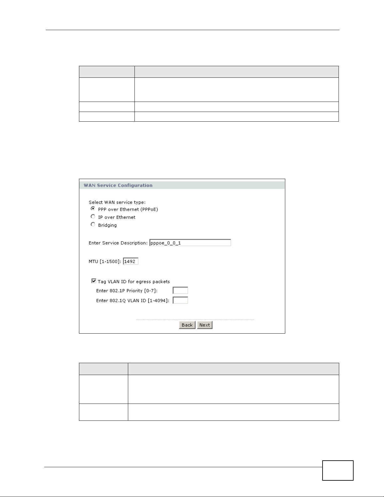
The following table describes the labels in this screen.
Table 15 WAN Configuration: WAN Interface
LABEL DESCRIPTION
Select a layer 2
interface for this
service
Back Click this button to return to the previous screen.
Next Click this button to continue.
5.5.1.2 Service Type
Use this screen to configure how you want the P-870HN-51D to connect to the
Internet.
Figure 32 WAN Configuration: Service Type
Chapter 5 WAN Setup
Select a PTM interface to use the DSL port as the WAN port and use
the VDSL technology for data transmission.
The following table describes the labels in this screen.
Table 16 WAN Configuration: Service Type
LABEL DESCRIPTION
Select WAN
service type
Enter Service
Description
P-870HN-51D User’s Guide
Select the method of encapsulation used by your ISP.
Choices are PPP over Ethernet (PPPoE), IP over Ethernet and
Bridging.
Specify a name for this connection or use the automatically generated
one.
75
Page 76

Chapter 5 WAN Setup
Table 16 WAN Configuration: Service Type
LABEL DESCRIPTION
Rate Limit Enter the maximum transmission rate in Kbps for tr affic sent through the
MTU [1-1500] Type the maximum size of each data packet, in bytes, that can move
Tag VLAN ID
for egress
packets
Enter 802.1P
Priority
Enter 802.1Q
VLAN ID
WAN connection. Otherwise, leave this field blank to disable the rate
limit.
This field is not available for an ATM connection.
through this interface. If a larger packet arrives, the P-870HN-51D
divides it into smaller fragments. Allowed values are 1 - 1500. Usually,
this value is 1500.
Select this option to add the VLAN tag (specified below) to the outgoing
traffic through this connection.
This field is available when the Connect interface is in VLAN MUX mode.
IEEE 802.1p defines up to 8 separate traffic types by inserting a tag into
a MAC-layer frame that contains bits to define class of service.
T ype the IEEE 802.1p priorit y level (from 0 to 7) to add to tr affic through
this connection. The greater the number, the higher the priority level.
This field is available when the Connect interface is in VLAN MUX mode.
Type the VLAN ID number (from 1 to 4094) for traffic through this
connection.
This field is available when the PTM interface is in VLAN MUX mode.
Back Click this button to return to the previous screen.
Next Click this button to continue.
5.5.1.3 WAN IP Address and DNS Server
The screen differs by the encapsulation you selected in the previous scr een. See
Section 5.6 on page 84 for more information.
76
P-870HN-51D User’s Guide
Page 77

Chapter 5 WAN Setup
PPPoE
This screen displays when you select PPP over Ethernet (PPPoE) in the WAN
Service Configuration screen.
Figure 33 WAN Configuration: PPPoE
The following table describes the labels in this screen.
Table 17 WAN Configuration: PPPoE
LABEL DESCRIPTION
PPP User Name Enter the user name exactly as your ISP assigned. If assigned a name
PPP Password Enter the password associated with the user name above .
PPPoE Service
Name
P-870HN-51D User’s Guide
in the form user@domain where domain identifies a service name,
then enter both components exactly as given.
Type the name of your PPPoE service here.
77
Page 78

Chapter 5 WAN Setup
Table 17 WAN Configuration: PPPoE
LABEL DESCRIPTION
Authentication
Method
Enable NAT Select this option to enable NAT on the P-870HN-51D. You can also
Dial on Demand Select this check box when you do not want the connection up all the
Inactivity
Timeout
Use Static IPv4
Address
IPv4 Address Enter the static IP address provided by your ISP.
Enable PPP
Debug Mode
The P-870HN-51D supports PAP (Password Authentication Protocol)
and CHAP (Challenge Handshake Authentication Protocol). CHAP is
more secure than PAP; however, PAP is readily available on more
platforms.
Use the drop-down list box to select an authentication protocol for
outgoing calls. Options are:
AUTO - Your P-870HN-51D accepts either CHAP or PAP when
requested by this remote node.
CHAP - Your P-870HN-51D accepts CHAP only.
PAP - Your P-870HN-51D accepts PAP only.
MSCHAP - Your P-870HN-51D accepts MSCHAP only. MS-CHAP is the
Microsoft version of the CHAP.
select the NAT Type you want the P-870HN-51D to implement. The
choices are as follows:
• Symmetric NAT (default) - Symmetric NAT maps requests from
the same private IP address and port to a different public source IP
address and/or port depending on the packet's destination IP
address.
• Port Restricted Cone NAT - Restricted cone NAT maps all
requests from the same private IP address and port to the same
public source IP address and port.
• Restricted Cone NAT - Restricted cone NAT maps all requests
from the same private IP address to the same public source IP
address.
• Full Cone NAT - In full cone NAT, all requests from the same
private IP address and port are mapped to the same public source
IP address and port. Someone on the Internet only needs to know
the mapping scheme in order to send packets to a device behind
the NAT router.
time and specify an idle time-out in the Inactivity Timeout field.
Specify an idle time-out when you select Dial on Demand. The
default setting is 0, which means the Internet session will not timeout.
A static IPv4 address is a fixed IP that your ISP gives you. A dynamic
IP address is not fixed; the ISP assigns you a different one each time
you connect to the Internet. Select this if you want to use a static IP
address instead of a dynamic IP address.
Select this option to display PPP debugging messages on the console.
78
P-870HN-51D User’s Guide
Page 79

Table 17 WAN Configuration: PPPoE
LABEL DESCRIPTION
Bridge PPPoE
Frames Between
WAN and Local
Ports
Enable IGMP
Multicast Proxy
Back Click this button to return to the previous screen.
Next Click this button to continue.
Select this option to forward PPPoE packets from the WAN port to the
LAN ports and from the LAN ports to the WAN port.
In addition to the P-870HN-51D's built-in PPPoE client, you can select
this to allow up to ten hosts on the LAN to use PPPoE client software
on their computers to connect to the ISP via the P-870HN-51D. Each
host can have a separate account and a public WAN IP address.
This is an alternative to NAT for application where NAT is not
appropriate.
Clear this if you do not need to allow hosts on the LAN to use PPPoE
client software on their computers to connect to the ISP.
Select this check box to have the P-870HN-51D act as an IGMP proxy
on this connection. This allows the P-870HN-51D to get subscribing
information and maintain a joined member list for each multicast
group. It can reduce multicast traffic significantly.
Chapter 5 WAN Setup
IPoE
This screen displays when you select IP over Ethernet in the WAN Service
Configuration screen.
Figure 34 WAN Configuration: IPoE
P-870HN-51D User’s Guide
79
Page 80

Chapter 5 WAN Setup
The following table describes the labels in this screen.
Table 18 WAN Configuration: IPoE
LABEL DESCRIPTION
Obtain an IP
address
automatically
Enable DHCP
Option 60
Vendor Class
Identifier
Enable DHCP
Option 61
IAID Enter the Identity Association Identifier (IAID) of the P-870HN-51D.
DUID Type Select Other to enter any string that identifies the P-870HN-51D in
A static IP address is a fixed IP that your ISP gives you. A dynamic IP
address is not fixed; the ISP assigns you a different one each time you
connect to the Internet. Select this if you want to get a dynamic IP
address from the ISP.
Select this to identify the vendor and functionality of the P-870HN51D in DHCP requests that the P-870HN-51D sends to a DHCP server
when getting a WAN IP address.
Enter the Vendor Class Identifier (Option 60), such as the type of the
hardware or firmware.
Select this to identify the P-870HN-51D in DHCP requests that the P870HN-51D sends to a DHCP server when getting a WAN IP address.
For example, the WAN connection index number.
the DUID field.
Select DUID-LL (DUID Based on Link-layer Address) to enter the P-
870HN-51D’s hardware address, that is the MAC address in the DUID
field.
Select DUID-EN (DUID Assigned by Vendor Base d on Enterprise
Number) to enter the vendor’s registered private enterprise number.
DUID Enter the DHCP Unique Identifier (DUID) of the P-870HN-51D.
Identifier Enter a unique identifier assigned by the vendor.
This field is available when you select DUID-EN in the DUID Type
field.
Enable DHCP
Option 125
Manufacturer
OUI
Product Class Enter the product class of the P-870HN-51D.
Model Name Enter the model name of the P-870HN-51D.
Serial Number Enter the serial number of the P-870HN-51D.
Use the following
Static IP address
WAN IP
Address
WAN Subnet
Mask
WAN gateway
IP Address
Back Click this button to return to the previous screen.
Next Click this button to continue.
Select this to add vendor specific information to DHCP requests that
the P-870HN-51D sends to a DHCP server when getting a WAN IP
address.
Specify the vendor’s OUI (Organization Unique Identifier). It is usually
the first three bytes of the MAC address.
Select this if you have a static IP address.
Enter the static IP address provided by your ISP.
Enter the subnet mask provided by your ISP.
Enter the gateway IP address provided by your ISP.
80
P-870HN-51D User’s Guide
Page 81

5.5.1.4 NAT, IGMP Multicast and Firewall Activation
The screen is available only when you select IP over Ethernet in the WAN
Service Configuration screen.
Figure 35 WAN Configuration: NAT, IGMP Multicast and Firewall Activation
Chapter 5 WAN Setup
The following table describes the labels in this screen.
Table 19 WAN Configuration: NAT, IGMP Multicast and Firewall Activation
LABEL DESCRIPTION
Enable NAT Select this option to enable NAT on the P-870HN-51D. You can also
select the NAT Type you want the P-870HN-51D to implement. The
choices are as follows:
• Symmetric NAT (default) - Symmetric NAT maps requests from
the same private IP address and port to a different public source IP
address and/or port depending on the packet's destination IP
address.
• Port Restricted Cone NAT - Restricted cone NAT maps all
requests from the same private IP address and port to the same
public source IP address and port.
• Restricted Cone NAT - Restricted cone NAT maps all requests
from the same private IP address to the same public source IP
address.
• Full Cone NAT - In full cone NAT, all requests from the same
private IP address and port are mapped to the same public source
IP address and port. Someone on the Internet only needs to know
the mapping scheme in order to send packets to a device behind
the NAT router.
Enable Firewall Select this check box to activate Firewall on this connection.
Enable IGMP
Multicast Proxy
Back Click this button to return to the previous screen.
Next Click this button to continue.
Select this check box to have the P-870HN-51D act as an IGMP proxy
on this connection. This allows the P-870HN-51D to get subscribing
information and maintain a joined member list for each multicast
group. It can reduce multicast traffic significantly.
P-870HN-51D User’s Guide
81
Page 82

Chapter 5 WAN Setup
5.5.1.5 Default Gateway
The screen is not available when you select Bridging in the WAN Service
Configuration screen.
Figure 36 WAN Configuration: Default Gateway
The following table describes the labels in this screen.
Table 20 WAN Configuration: Default Gateway: PPPoE, PPPoA, IPoE or IPoA
LABEL DESCRIPTION
Selected Default
Gateway
Interfaces
Back Click this button to return to the previous screen.
Next Click this button to continue.
Select a WAN interface through which you want to forward the traffic.
5.5.1.6 DNS Server
The screen is not available when you select Bridging in the WAN Service
Configuration screen.
Figure 37 WAN Configuration: DNS Server
82
P-870HN-51D User’s Guide
Page 83

The following table describes the labels in this screen.
Table 21 WAN Configuration: DNS Server
LABEL DESCRIPTION
Obtain DNS info
from a WAN
interface
WAN Interface
selected
Use the following
Static DNS IP
address
Primary DNS
server
Secondary
DNS server
Back Click this button to return to the previous screen.
Next Click this button to continue.
Select this to have the P-870HN-51D get the DNS server addresses
from the ISP automatically.
Select a WAN interface through which you want to obtain the DNS
related information.
Select this to have the P-870HN-51D use the DNS server addresses
you configure manually.
Enter the first DNS server address assigned by the ISP.
Enter the second DNS server address assigned by the ISP.
5.5.1.7 Configuration Summary
Chapter 5 WAN Setup
This read-only screen shows the current WAN connection settings.
Figure 38 WAN Configuration: Configuration Summary
P-870HN-51D User’s Guide
83
Page 84

Chapter 5 WAN Setup
The following table describes the labels in this screen.
Table 22 WAN Configuration: Configuration Summary
LABEL DESCRIPTION
Connection Type This is the encapsulation method used by this connection.
Service Name This is the name of the service.
Service Category This is the ATM traffic class.
IP Address This shows whether the WAN IP address is assigned by the ISP,
Service State This shows whether this service is active or not.
NAT This shows whether NAT is active or not for this connection.
NAT Type This shows the type of NAT implemented for this connection.
Firewall This shows whether Firewall is active or not for this connection.
Quality Of
Service
IGMP Multicast This shows whether IGMP multicasting is active or not for this
Back Click this button to return to the previous screen.
Apply/Save Click this button to save your changes.
This field is blank for a PTM or Ethernet WAN conenction.
manually configured or not configurable.
This shows whether QoS is active or not for this connection.
connection.
5.6 Technical Reference
The following section contains additional technical information about the P-870HN51D features described in this chapter.
Encapsulation
Be sure to use the encapsulation method required by your ISP. The P-870HN-51D
can work in bridge mode or routing mode. When the P-870HN-51D is in routing
mode, it supports the following methods.
IP over Ethernet
IP over Ethernet (IPoE) is an alternative to PPPoE. IP packets are being delivered
across an Ethernet network, without using PPP encapsulation. They are routed
between the Ethernet interface and the WAN interface and then formatted so that
they can be understood in a bridged environment. For instance, it encapsulates
routed Ethernet frames into bridged Ethernet cells.
84
P-870HN-51D User’s Guide
Page 85

Chapter 5 WAN Setup
PPP over Ethernet
Point-to-Point Protocol over Ethernet (PPPoE) provides access control and billing
functionality in a manner similar to dial-up services using PPP. PPPoE is an IETF
standard (RFC 2516) specifying how a personal computer (PC) interacts with a
broadband modem (DSL, cable, wireless, etc.) connection.
For the service provider, PPPoE offers an access and authentication method that
works with existing access control systems (for example RADIUS).
One of the benefits of PPPoE is the ability to let you access one of multiple network
services, a function known as dynamic servic e selection. This enables the service
provider to easily create and offer new IP services for individuals.
Operationally, PPPoE saves significant effort for both yo u and the ISP or carri er, as
it requires no specific configuration of the broadband modem at the customer site .
By implementing PPPoE directly on the P-870HN-51D (rather than individual
computers), the computers on the LAN do not need PPPoE software installed,
since the P-870HN-51D does that part of the task. Furthermore, with NAT, all of
the LAN's computers will have access.
IP Address Assignment
A static IP is a fixed IP that your ISP gives y ou. A dynamic IP is not fix e d; the ISP
assigns you a different one each time. The Single User Account feature can be
enabled or disabled if you have either a dynamic or static IP. However the
encapsulation method assigned influences your choices for IP address and default
gateway.
Full Cone NAT
In full cone NAT, the NAT router maps all outgoing packets from an internal IP
address and port to a single IP address and port on the external network. The NA T
router also maps packets coming to that external IP address and port to the
internal IP address and port.
In the following example, the P-870HN-51D maps the source address of all
packets sent from the internal IP address 1 and port A to IP address 2 and port B
on the external network. The P-870HN-51D also performs NAT on all incoming
P-870HN-51D User’s Guide
85
Page 86

Chapter 5 WAN Setup
packets sent to IP address 2 and port B and forwards them to IP address 1, port
A.
Figure 39 Full Cone NAT Example
1, A
2, B
Symmetric NAT
The full, restricted and port restricted cone NAT types use the same mapping for
an outgoing packet’s source address regardless of the destination IP address and
port. In symmetric NAT, the mapping of an outgoing packet’s source address to a
source address in another network is different for each different destination IP
address and port.
In the following example, the P-870HN-51D maps the source address IP address 1
and port A to IP address 2 and port B on the external network for packets sent to
IP address 3 and port C. The P-870HN-51D uses a different mapping (IP address
2 and port M) for packets sent to IP address 4 and port
A host on the external network (IP address 3 and port C for example) can only
send packets to the internal host via the external IP address and port that the NA T
router used in sending a packet to the external host’s IP address and port. So in
D.
86
P-870HN-51D User’s Guide
Page 87

Chapter 5 WAN Setup
the example, only 3, C is allowed to send packets to 2, B and onl y 4, D is allowed
to send packets to 2, M.
Figure 40 Symmetric NAT
3, C
2, B
4, D
1, A
2, M
4, E
5, B
Introduction to VLANs
A Virtual Local Area Network (VLAN) allows a physical network to be partitioned
into multiple logical networks. Devices on a logical network belong to one group. A
device can belong to more than one group. With VLAN, a device cannot directly
talk to or hear from devices that are not in the same group(s); the traffic must
first go through a router.
In Multi-Tenant Unit (MTU) applications, VLAN is vital in providing isolation and
security among the subscribers. When properly configured, VLAN prevents one
subscriber from accessing the netw ork resources of another on the same LAN,
thus a user will not see the printers and hard disks of another user in the same
building.
VLAN also increases network performance by limiting broadcasts to a smaller and
more manageable logical broadcast domain. In traditional switched environments,
all broadcast packets go to each and every individual port. Wit h VLAN, all
broadcasts are confined to a specific broadcast domain.
Introduction to IEEE 802.1Q Tagged VLAN
A tagged VLAN uses an explicit tag (VLAN ID) in the MAC header to identify the
VLAN membership of a frame across bridges - they are not confined to the switch
on which they were created. The VLANs can be created statically by hand or
dynamically through GVRP. The VLAN ID associates a frame with a specific VLAN
and provides the information that switches need to process the frame across the
network. A tagged frame is four bytes longer than an untagged frame and
P-870HN-51D User’s Guide
87
Page 88

Chapter 5 WAN Setup
contains two bytes of TPID (Tag Protocol Identifier), residing within the typ e/
length field of the Ethernet frame) and two bytes of TCI (Tag Control Information),
starts after the source address field of the Ethernet frame).
The CFI (Canonical Format Indicator) is a single-bit flag, always set to zero for
Ethernet switches. If a frame received at an Ethernet port has a CFI set to 1, then
that frame should not be forwarded as it is to an untagged port. The remaining
twelve bits define the VLAN ID, giving a possible maximum number of 4,096
VLANs. Note that user priority and VLAN ID are independent of each other. A
frame with VID (VLAN Identifier) of null (0) is called a pr iority frame, meaning that
only the priority level is significant and the default VID of the ingress port is given
as the VID of the frame. Of the 4096 possible VIDs, a VID of 0 is used to identify
priority frames and value 4095 (FFF) is reserved, so the maximum possible VLAN
configurations are 4,094.
TPID
2 Bytes
User Priority
3 Bits
CFI
1 Bit
VLAN ID
12 Bits
Multicast
IP packets are transmitted in either one of two ways - Unicas t ( 1 sen der - 1
recipient) or Broadcast (1 sender - everybody on the network). Multicast delivers
IP packets to a group of hosts on the network - not everybody and not just 1.
Internet Group Multicast Protocol (IGMP) is a network-layer protocol used to
establish membership in a Multicast group - it is not used to carry user data. IGMP
version 2 (RFC 2236) is an improvement over version 1 (RFC 1112) but IGMP
version 1 is still in wide use. If you would like to read more detailed information
about interoperability between IGMP version 2 and version 1, please see sections
4 and 5 of RFC 2236. The class D IP address is used to identify host groups and
can be in the range 224.0.0.0 to 239.255.255.255. The addr ess 224.0.0.0 is not
assigned to any group and is used by IP multicast computers. The address
224.0.0.1 is used for query messages and is assigned to the permanent group of
all IP hosts (including gateways). All host s must join t he 224.0.0.1 group in order
to participate in IGMP. The address 224.0.0.2 is assigned to the multicast routers
group.
88
At start up, the P-870HN-51D queries all directly connected networks to gather
group membership. After that, the P-870HN-51D periodically updates this
information.
DNS Server Address Assignment
Use Domain Name System (DNS) to map a domain name to its corresponding IP
address and vice versa, for instance, the IP address of www.zyxel.com is
P-870HN-51D User’s Guide
Page 89

Chapter 5 WAN Setup
204.217.0.2. The DNS server is extremely important because without it, you must
know the IP address of a computer before you can access it.
The P-870HN-51D can get the DNS server addresses in the following ways.
1 The ISP tells you the DNS server addresses, usually in the form of an information
sheet, when you sign up. If your ISP gives you DNS server addresses, manually
enter them in the DNS server fields.
2 If your ISP dynamically assigns the DNS server IP addresses (along with the P-
870HN-51D’s WAN IP address), set the DNS server fields to get the DNS server
address from the ISP.
P-870HN-51D User’s Guide
89
Page 90

Chapter 5 WAN Setup
90
P-870HN-51D User’s Guide
Page 91

CHAPTER 6
LAN Setup
6.1 Overview
A Local Area Network (LAN) is a shared communication system to which many
computers are attached. A LAN is usually located in one immediate area such as a
building or floor of a building.
The LAN screens can help you configure a LAN DHCP server and manage IP
addresses.
LAN
• See Section 6.4 on page 95 for more information on LANs.
• See Appendix E on page 321 for more information on IP addresses and
subnetting.
6.1.1 What You Can Do in this Chapter
The LAN IP screen lets you set the LAN IP address and subnet mask of your
ZyXEL device and configure other LAN TCP/IP settings (Section 6.3 on page 93).
P-870HN-51D User’s Guide
91
Page 92

Chapter 6 LAN Setup
6.2 What You Need To Know
IP Address
Similar to the way houses on a street share a common street name, so too do
computers on a LAN share one common network number. This is known as an
Internet Protocol address.
Subnet Mask
The subnet mask specifies the network number portion of an IP address. Your P870HN-51D will compute the subnet mask automatically based on the IP address
that you entered. You don't need to change the subnet mask computed by the P870HN-51D unless you are instructed to do otherwise.
DHCP
DHCP (Dynamic Host Configuration Protocol) allows clients to obtain TCP/IP
configuration at start-up from a server. This P-870HN-51D has a built-in DHCP
server capability that assigns IP addresses and DNS servers to systems that
support DHCP client capability.
DHCP Relay
You can also config ure the P-870HN-51D to relay client DHCP requests to a DHCP
server and the server’s responses back to the clients.
RIP
RIP (Routing Information Protocol) allows a router to exchange routing
information with other routers.
Multicast and IGMP
Traditionally, IP packets are transmitted in one of either two ways - Unicast (1
sender - 1 recipient) or Broadcast (1 sender - everybody on the network).
Multicast delivers IP packets to a group of hosts on the network - not everybody
and not just 1.
IGMP (Internet Group Multicast Protocol) is a network-layer protocol used to
establish membership in a Multicast group - it is not used to carry user data.
There are two versions 1 and 2. IGMP version 2 is an improvement over version 1
but IGMP version 1 is still in wide use.
92
P-870HN-51D User’s Guide
Page 93

DNS
DNS (Domain Name System) maps a domain name to its corresponding IP
address and vice versa. The DNS server is extremely important because without
it, you must know the IP address of a computer before you can access it. The DNS
server addresses you enter when you set up DHCP are passed to the client
machines along with the assigned IP address and subnet mask.
6.3 The LAN IP Screen
Click Network > LAN to open the IP screen. See Section 6.4 on page 95 for
background information. Use this screen to set the Local Area Network IP address
and subnet mask of your P-870HN-51D.
Figure 41 LAN > IP
Chapter 6 LAN Setup
P-870HN-51D User’s Guide
93
Page 94

Chapter 6 LAN Setup
The following table describes the fields in this screen.
Table 23 LAN > IP
LABEL DESCRIPTION
LAN TCP/IP
Group Name Select the interface group for which you want to configure the LAN
IP Address Enter the LAN IP address you want to assign to your P-870HN-51D in
IP Subnet Mask Type the subnet mask of your network in dotted decimal notation, for
DHCP Setup
Enable DHCP Select this to have the P-870HN-51D act as a DHCP server or DHCP
DHCP Server Select this option to have the P-870HN-51D assign IP addresses and
TCP/IP settings. See Chapter 19 on page 213 for how to create a new
interface group.
dotted decimal notation, for example, 192.168.1.1 (factory default).
example 255.255.255.0 (factory default).
relay agent.
Otherwise, deselect this to not have the P-870HN-51D provide any
DHCP services. The DHCP server will be disabled.
provide subnet mask, gateway, and DNS server information to the
network. The P-870HN-51D is the DHCP server for the network.
When the P-870HN-51D acts as a DHCP server, the following items
need to be set:
IP Pool
Starting
Address
Pool Size This field specifies the size, or count of the IP address pool.
DHCP Relay Select this option to have the P-870HN-51D forward DHCP request to
Relay Server If you select DHCP Relay, enter the IP address of the DHCP server.
DNS Servers Assigned by DHCP Server
Obtain DNS info
from a WAN
interface
Use the following Static DNS IP address
First DNS
Server
Second DNS
Server
IGMP Snooping
Enable IGMP
Snooping
Standard
Mode
This field specifies the first of the contiguous addresses in the IP
address pool.
the DHCP server.
When a LAN client sends a DNS query to the P-870HN-51D, the P870HN-51D forwards the query to the system DNS server configured
in the WAN interface you select.
If you do not configure DNS servers on the selected WAN inteface, the
P-870HN-51D uses the LAN IP address and tells the DHCP clients on
the LAN that itself is the DNS server.
Enter the first DNS (Domain Name System) server IP address the P870HN-51D passes to the DHCP clients.
Enter the second DNS (Domain Name System) server IP address the
P-870HN-51D passes to the DHCP clients.
Select this option to enable IGMP snooping. This allows the P-870HN51D to passively learn multicast group.
Select this to have the P-870HN-51D forward multicast packets to a
port that joins the multicast group and broadcast unknown multicast
packets from the WAN to all LAN ports.
94
P-870HN-51D User’s Guide
Page 95

Table 23 LAN > IP
LABEL DESCRIPTION
Blocking Mode Select this to have the P-870HN-51D block all unknown multicast
packets from the WAN.
Enable IP Alias Select the check box to configure anothe r LAN network for the P-
870HN-51D.
IP Address Enter the IP address of your P-870HN-51D in dotted decimal notation.
IP Subnet
Mask
Apply Click Apply to save your changes back to the P-870HN-51D.
Type the subnet mask of your network in dotted decimal notation, for
example 255.255.255.0 (factory default).
6.4 Technical Reference
The following section contains additional technical information about the P-870HN51D features described in this chapter.
Chapter 6 LAN Setup
LANs, WANs and the ZyXEL Device
The actual physical connection determines whether the P-870HN-51D ports are
LAN or WAN ports. There are two separate IP networks, one inside the LAN
network and the other outside the WAN network as shown next.
Figure 42 LAN and WAN IP Addresses
LAN
WAN
DHCP Setup
DHCP (Dynamic Host Configuration Protocol, RFC 2131 and RFC 2132) allows
individual clients to obtain TCP/IP configuration at start-up from a server. Y ou can
configure the P-870HN-51D as a DHCP server or disable it. When configured as a
server, the P-870HN-51D provides the TCP/IP configuration for the clients. If you
turn DHCP service off, you must have another DHCP server on your LAN, or else
the computer must be manually configured.
P-870HN-51D User’s Guide
95
Page 96

Chapter 6 LAN Setup
IP Pool Setup
The P-870HN-51D is pre-configured with a pool of IP addresses for the DHCP
clients (DHCP Pool). See the product specif ic a t i o ns in the appendices. Do not
assign static IP addresses from the DHCP pool to your LAN computers.
LAN TCP/IP
The P-870HN-51D has built-in DHCP server capability that assigns IP addresses
and DNS servers to systems that support DHCP client capability.
IP Address and Subnet Mask
Similar to the way houses on a street share a common street name, so too do
computers on a LAN share one common network number.
Where you obtain your network number depends on your particular situation. If
the ISP or your network administrator assigns you a block of registered IP
addresses, follow their instructions in selecting the IP addresses and the subnet
mask.
If the ISP did not explicitly give you an IP network number, then most likely you
have a single user account and the ISP will assign you a dynamic IP address when
the connection is established. If this is the case, it is recommended that you select
a network number from 192.168.0.0 to 192.168.255.0 and you must enable the
Network Address Translation (NAT) feature of the P-870HN-51D. The Internet
Assigned Number Authority (IANA) reserved this block of addresses sp ecifically for
private use; please do not use any other number unless you are told otherwise.
Let's say you select 192.168.1.0 as the network number; which covers 254
individual addresses, from 192.168.1.1 to 192.168.1.254 (zero and 255 are
reserved). In other words, the first three numbers specify the network number
while the last number identifies an individual computer on that network.
Once you have decided on the network number , pick an IP address that is easy to
remember, for instance, 192.168.1.1, for your P-870HN-51D, but make sure that
no other device on your network is using that IP address.
The subnet mask specifies the network number portion of an IP address. Your P870HN-51D will compute the subnet mask automatically based on the IP address
that you entered. You don't need to change the subnet mask computed by the P870HN-51D unless you are instructed to do otherwise.
96
Private IP Addresses
Every machine on the Internet must have a unique address. If your networks are
isolated from the Internet, for example, only between your two branch offices, you
can assign any IP addresses to the hosts without problems. However, the Internet
P-870HN-51D User’s Guide
Page 97

Chapter 6 LAN Setup
Assigned Numbers Authority (IANA) has reserve d the following three blocks of IP
addresses specifically for private networks:
• 10.0.0.0 — 10.255.255.255
• 172.16.0.0 — 172.31.255.255
• 192.168.0.0 — 192.168.255.255
You can obtain your IP address from the IANA, from an ISP or it can be assigned
from a private network. If you belong to a small organization and your Internet
access is through an ISP, the ISP can provide you with the Internet addresses for
your local networks. On the other hand, if you are part of a much larger
organization, you should consult your network administrator for the appropriate IP
addresses.
Note: Regardless of your particular situation, do not create an arbitrary IP address;
always follow the guidelines above. For more information on address
assignment, please refer to RFC 1597, “Address Allocation for Private
Internets” and RFC 1466, “Guidelines for Management of IP Address Space”.
Multicast
Traditionally, IP packets are transmitted in one of either two ways - Unicast (1
sender - 1 recipient) or Broadcast (1 sender - everybody on the network).
Multicast delivers IP packets to a group of hosts on the network - not everybody
and not just 1.
IGMP (Internet Group Multicast Protocol) is a network-layer protocol used to
establish membership in a Multicast group - it is not used to carry user data. IGMP
version 2 (RFC 2236) is an improvement over version 1 (RFC 1112) but IGMP
version 1 is still in wide use. If you would like to read more detailed information
about interoperability between IGMP version 2 and version 1, please see sections
4 and 5 of RFC 2236. The class D IP address is used to identify host groups and
can be in the range 224.0.0.0 to 239.255.255.255. The addr ess 224.0.0.0 is not
assigned to any group and is used by IP multicast computers. The address
224.0.0.1 is used for query messages and is assigned to the permanent group of
all IP hosts (including gateways). All host s must join t he 224.0.0.1 group in order
to participate in IGMP. The address 224.0.0.2 is assigned to the multicast routers
group.
The P-870HN-51D supports both IGMP version 1 (IGMP-v1) and IGMP version 2
(IGMP-v2). At start up, the P-870HN-51D queries all directly connected networks
to gather group membership. After that, the P-870HN-51D periodically updates
this information. IP multicasting can be enabled/disabled on the P-870HN-51D
LAN and/or WAN interfaces in the web configur ator (LAN; WAN). Select None to
disable IP multicasting on these interfaces.
P-870HN-51D User’s Guide
97
Page 98

Chapter 6 LAN Setup
IP Alias
IP alias allows you to partitio n a physi c a l network into different logical networks
over the same Ethernet interface. The P-870HN-51D supports three logical LAN
interfaces via its single physical Ethernet interface with the P-870HN-51D itself as
the gateway for each LAN network.
When you use IP alias, you can also configure firewall rules to control access
between the LAN's logical networks (subnets).
Note: Make sure that the subnets of the logical networks do not overlap.
The following figure shows a LAN divided into subnets A and B.
Figure 43 Physical Network & Partitioned Logical Networks
Ethernet
Interface
A: 192.168.1.1 - 192.168.1.24
B: 192.168.2.1 - 192.168.2.24
98
P-870HN-51D User’s Guide
Page 99

CHAPTER 7
Wireless LAN
7.1 Overview
This chapter describes how to perform tasks related to setting up and optimizing
your wireless network, includ i ng the following.
• Turning the wireless connection on or off.
• Configuring a name, wireless channel and security for the network.
• Using WiFi Protected Setup (WPS) to configure your wireless network.
• Using a MAC (Media Access Control) address filter to restrict access to the
wireless network.
See Chapter 2 on page 27 for a tutorial showing how to set up your wireless
connection in an example scenario.
See Section 7.9 on page 117 for advanced technical information on wireless
networks.
7.1.1 What You Can Do in this Chapter
This chapter describes the P-870HN-51D’s Network > Wireless LAN screens.
Use these screens to set up your P-870HN-51D’s wireless connection.
•The General screen lets you turn the wireless connection on or off, set up
wireless security and make other basic configuration changes (Section 7.4 on
page 102). You can also configure the MAC filter to allow or block access to the
P-870HN-51D based on the MAC addresses of the wireless stations.
•The More AP screen lets you set up multiple wireless networks on your P-
870HN-51D (Section 7.5 on page 112).
•Use the WPS screen and the WPS Station screen to use WiFi Protected Setup
(WPS). WPS lets you set up a secure network quickly, when connecting to other
WPS-enabled devices.
Use the WPS screen (see Section 7.6 on page 113) to enable or disable WPS,
generate a security PIN (Personal Identification Number) and see information
about the P-870HN-51D’s WPS status.
Use the WPS Station (see Section 7.7 on page 115) screen to set up WPS by
pressing a button or using a PIN.
P-870HN-51D User’s Guide
99
Page 100

Chapter 7 Wireless LAN
•The Advanced Setup screen lets you change the wireless mode, and make
other advanced wireless configuration changes (Section 7.8 on page 116).
You don’t necessarily need to use all these screens to set up your wireless
connection. For example, you may just want to set up a network name, a wireless
radio channel and some security in the General screen.
7.2 What You Need to Know
Wireless Basics
“Wireless” is essentially radio communication. In the same way that walkie-talkie
radios send and receive information over the airwaves, wireless networking
devices exchange information with one another. A wireless networking device is
just like a radio that lets your computer exchange information with radios
attached to other computers. Like walkie-talkies, most wireless networking
devices operate at radio frequency bands that are open to the public and do not
require a license to use. However, wirele ss networking is different from that of
most traditional radio communications in that there a number of wireless
networking standards available with different methods of data encryption.
Wireless Network Construction
Wireless networks consist of wireless clients, access points and bridges.
• A wireless client is a radio connected to a user ’s computer.
• An access point is a radio with a wired connection to a network, which can
connect with numerous wireless clients and let them access the network.
• A bridge is a radio that relays communications between access points and
wireless clients, extending a network’s range.
Traditionally, a wireless network operates in one of two ways.
• An “infrastructure” type of network has one or more access points and one or
more wireless clients. The wireless clients connect to the access points.
• An “ad-hoc” type of network is one in which there is no access point. Wireless
clients connect to one another in order to exchange information.
Network Names
Each network must have a name, referred to as the SSID - “Ser vice Set
IDentifier”. The “service set” is the network, so the “service set ident i fier” is the
network’s name. This helps you identify your wireless network when wireless
networks’ coverage areas overlap and you have a variety of networks to choose
from.
100
P-870HN-51D User’s Guide
 Loading...