

Page 1

P-660R-T1 v3
ADSL2+ Access Router
User’s Guide
Version 3.40
10/2008
Edition 1
DEFAULT LOGIN
IP Address http://192.168.1.1
User Name admin
Password 1234
www.zyxel.com
Page 2

Page 3

About This User's Guide
About This User's Guide
Intended Audience
This manual is intended for people who want to configure the ZyXEL Device using the web
configurator. You should have at least a basic knowledge of TCP/IP networking concepts and
topology.
Related Documentation
• Quick Start Guide
The Quick Start Guide is designed to help you get up and running right away. It contains
information on setting up your network and configuring for Internet access.
" It is recommended you use the web configurator to configure the ZyXEL
Device.
• Supporting Disc
Refer to the included CD for support documents.
• ZyXEL Web Site
Please refer to www.zyxel.com
certifications.
User Guide Feedback
Help us help you. Send all User Guide-related comments, questions or suggestions for
improvement to the following address, or use e-mail instead. Thank you!
The Technical Writing Team,
ZyXEL Communications Corp.,
6 Innovation Road II,
Science-Based Industrial Park,
Hsinchu, 300, Taiwan.
E-mail: techwriters@zyxel.com.tw
Disclaimer
Graphics in this book may differ slightly from the product due to differences in operating
systems, operating system versions, or if you installed updated firmware/software for your
device. Every effort has been made to ensure that the information in this manual is accurate.
for additional support documentation and product
P-660R-T1 v3 User’s Guide
3
Page 4

Document Conventions
Document Conventions
Warnings and Notes
These are how warnings and notes are shown in this User’s Guide.
1 Warnings tell you about things that could harm you or your device.
" Notes tell you other important information (for example, other things you may
need to configure or helpful tips) or recommendations.
Syntax Conventions
• The P-660R-T1 v3 may be referred to as the “ZyXEL Device”, the “device”, the “system”
or the “product” in this User’s Guide.
• Product labels, screen names, field labels and field choices are all in bold font.
• A key stroke is denoted by square brackets and uppercase text, for example, [ENTER]
means the “enter” or “return” key on your keyboard.
• “Enter” means for you to type one or more characters and then press the [ENTER] key.
“Select” or “choose” means for you to use one of the predefined choices.
• A right angle bracket ( > ) within a screen name denotes a mouse click. For example,
Maintenance > Log > Log Setting means you first click Maintenance in the navigation
panel, then the Log sub menu and finally the Log Setting tab to get to that screen.
• Units of measurement may denote the “metric” value or the “scientific” value. For
example, “k” for kilo may denote “1000” or “1024”, “M” for mega may denote “1000000”
or “1048576” and so on.
• “e.g.,” is a shorthand for “for instance”, and “i.e.,” means “that is” or “in other words”.
4
P-660R-T1 v3 User’s Guide
Page 5
Document Conventions
Icons Used in Figures
Figures in this User’s Guide may use the following generic icons. The ZyXEL Device icon is
not an exact representation of your device.
ZyXEL Device Computer Notebook computer
Server Firewall Telephone
Router Switch
P-660R-T1 v3 User’s Guide
5
Page 6

Safety Warnings
Safety Warnings
1 For your safety, be sure to read and follow all warning notices and instructions.
• Do NOT use this product near water, for example, in a wet basement or near a swimming
pool.
• Do NOT expose your device to dampness, dust or corrosive liquids.
• Do NOT store things on the device.
• Do NOT install, use, or service this device during a thunderstorm. There is a remote risk
of electric shock from lightning.
• Connect ONLY suitable accessories to the device.
• Do NOT open the device or unit. Opening or removing covers can expose you to
dangerous high voltage points or other risks. ONLY qualified service personnel should
service or disassemble this device. Please contact your vendor for further information.
• Make sure to connect the cables to the correct ports.
• Place connecting cables carefully so that no one will step on them or stumble over them.
• Always disconnect all cables from this device before servicing or disassembling.
• Use ONLY an appropriate power adaptor or cord for your device.
• Connect the power adaptor or cord to the right supply voltage (for example, 110V AC in
North America or 230V AC in Europe).
• Do NOT allow anything to rest on the power adaptor or cord and do NOT place the
product where anyone can walk on the power adaptor or cord.
• Do NOT use the device if the power adaptor or cord is damaged as it might cause
electrocution.
• If the power adaptor or cord is damaged, remove it from the device and the power source.
• Do NOT attempt to repair the power adaptor or cord. Contact your local vendor to order a
new one.
• Do not use the device outside, and make sure all the connections are indoors. There is a
remote risk of electric shock from lightning.
• Do NOT obstruct the device ventilation slots, as insufficient airflow may harm your
device.
• Use only No. 26 AWG (American Wire Gauge) or larger telecommunication line cord.
• Antenna Warning! This device meets ETSI and FCC certification requirements when
using the included antenna(s). Only use the included antenna(s).
6
This product is recyclable. Dispose of it properly.
P-660R-T1 v3 User’s Guide
Page 7

Safety Warnings
P-660R-T1 v3 User’s Guide
7
Page 8

Safety Warnings
8
P-660R-T1 v3 User’s Guide
Page 9

Contents Overview
Contents Overview
Introduction ............................................................................................................................25
Introducing the ZyXEL Device ...................................................................................................27
Introducing the Web Configurator .............................................................................................. 31
Status ......................................................................................................................................35
Device Information ..................................................................................................................... 37
System Logs .............................................................................................................................. 39
Traffic Statistics .......................................................................................................................... 41
Quick Start Wizard .................................................................................................................43
Quick Start Wizard..................................................................................................................... 45
Interface Setup ....................................................................................................................... 51
Internet Setup ............................................................................................................................ 53
LAN Setup ................................................................................................................................. 67
Advanced Setup .....................................................................................................................75
Static Route ............................................................................................................................... 77
Network Address Translation (NAT) .......................................................................................... 81
Quality of Service (QoS) ............................................................................................................ 91
ADSL ......................................................................................................................................... 99
Firewall .................................................................................................................................... 101
Access Management ...........................................................................................................103
Access Control ........................................................................................................................ 105
Filters ....................................................................................................................................... 109
SNMP .......................................................................................................................................115
Universal Plug-and-Play (UPnP) ..............................................................................................117
Dynamic DNS Setup ................................................................................................................ 129
CWMP ..................................................................................................................................... 131
Maintenance .........................................................................................................................135
Administrator Settings ............................................................................................................. 137
Time Zone ................................................................................................................................ 139
Firmware .................................................................................................................................. 141
System Restart ........................................................................................................................ 149
Diagnostic ................................................................................................................................ 151
[Document Title]
9
Page 10

Contents Overview
Troubleshooting and Product Specifications ...................................................................153
Troubleshooting ....................................................................................................................... 155
Product Specifications ............................................................................................................. 159
Appendices and Index ......................................................................................................... 165
10
[Document Title]
Page 11

Table of Contents
Table of Contents
About This User's Guide ..........................................................................................................3
Document Conventions............................................................................................................4
Safety Warnings........................................................................................................................6
Contents Overview ...................................................................................................................9
Table of Contents....................................................................................................................11
List of Figures .........................................................................................................................19
List of Tables...........................................................................................................................23
Part I: Introduction................................................................................. 25
Chapter 1
Introducing the ZyXEL Device...............................................................................................27
1.1 Overview .............................................................................................................................. 27
1.2 Ways to Manage the ZyXEL Device .................................................................................... 27
1.3 Good Habits for Managing the ZyXEL Device ..................................................................... 28
1.4 Applications for the ZyXEL Device ...................................................................................... 28
1.4.1 Internet Access ..........................................................................................................28
1.5 LEDs (Lights) ....................................................................................................................... 29
1.6 The RESET Button .............................................................................................................. 30
1.6.1 Using the Reset Button .............................................................................................. 30
Chapter 2
Introducing the Web Configurator ........................................................................................31
2.1 Overview .............................................................................................................................. 31
2.1.1 Accessing the Web Configurator ................................................................................ 31
2.2 Web Configurator Main Screen ........................................................................................... 32
2.2.1 Navigation Panel ........................................................................................................ 33
2.2.2 Main Window ..............................................................................................................34
Part II: Status.......................................................................................... 35
[Document Title]
11
Page 12

Table of Contents
Chapter 3
Device Information..................................................................................................................37
3.1 Overview .............................................................................................................................. 37
3.2 The Device Info Screen ....................................................................................................... 37
Chapter 4
System Logs............................................................................................................................39
4.1 Overview .............................................................................................................................. 39
4.2 The System Log Screen ......................................................................................................39
Chapter 5
Traffic Statistics ......................................................................................................................41
5.1 Overview .............................................................................................................................. 41
5.2 The Statistics Screen ........................................................................................................... 41
Part III: Quick Start Wizard .................................................................... 43
Chapter 6
Quick Start Wizard ..................................................................................................................45
6.1 Overview .............................................................................................................................. 45
6.2 Quick Start Wizard ............................................................................................................... 45
Part IV: Interface Setup.......................................................................... 51
Chapter 7
Internet Setup..........................................................................................................................53
7.1 Overview .............................................................................................................................. 53
7.1.1 What You Can Do in the Internet Screens ................................................................. 53
7.1.2 What You Need to Know About ADSL Internet Access .............................................. 53
7.1.3 Before You Begin ....................................................................................................... 54
7.2 The Internet Screen ............................................................................................................. 55
7.2.1 Dynamic IP Address ................................................................................................... 56
7.2.2 Static IP Address ........................................................................................................58
7.2.3 PPPoA/PPPoE ........................................................................................................... 60
7.2.4 Bridge Mode ............................................................................................................... 62
7.2.5 The PVCs Summary Screen ...................................................................................... 62
7.3 WAN Technical Reference ................................................................................................... 63
7.3.1 Encapsulation ............................................................................................................. 63
7.3.2 Multiplexing ................................................................................................................ 64
12
[Document Title]
Page 13

Table of Contents
7.3.3 VPI and VCI ............................................................................................................... 64
7.3.4 IP Address Assignment .............................................................................................. 64
7.3.5 Always-On Connection (PPP) .................................................................................... 65
7.3.6 ATM QoS .................................................................................................................... 65
7.3.7 ATM Traffic Classes ................................................................................................... 66
Chapter 8
LAN Setup................................................................................................................................67
8.1 Overview .............................................................................................................................. 67
8.1.1 What You Can Do in the LAN Screens ....................................................................... 67
8.1.2 What You Need To Know About LAN ......................................................................... 67
8.2 The LAN Screen .................................................................................................................. 68
8.2.1 The DHCP IP Pool Summary Screen ........................................................................ 70
8.3 LAN Technical Reference ....................................................................................................71
8.3.1 LANs, WANs and the ZyXEL Device .......................................................................... 71
8.3.2 DHCP Setup ...............................................................................................................71
8.3.3 DNS Server Addresses .............................................................................................. 72
8.3.4 LAN TCP/IP ................................................................................................................ 72
8.3.5 RIP Setup ................................................................................................................... 73
8.3.6 Multicast ..................................................................................................................... 74
Part V: Advanced Setup ........................................................................ 75
Chapter 9
Static Route ............................................................................................................................. 77
9.1 Overview ............................................................................................................................. 77
9.1.1 What You Can Do in the Static Route Screens .......................................................... 77
9.2 The Routing Table List Screen ............................................................................................ 78
9.2.1 The Static Route Screen ............................................................................................ 78
Chapter 10
Network Address Translation (NAT)......................................................................................81
10.1 Overview ............................................................................................................................ 81
10.1.1 What You Can Do in the NAT Screens ..................................................................... 81
10.1.2 What You Need To Know About NAT ....................................................................... 81
10.2 The NAT Screen ................................................................................................................ 82
10.3 The DMZ Screen ............................................................................................................... 83
10.4 The Virtual Server Screen .................................................................................................84
10.4.1 Configuring Servers Behind Port Forwarding (Example) ......................................... 84
10.4.2 Configuring the Virtual Server Screen ...................................................................... 85
10.5 The IP Address Mapping Screen ....................................................................................... 86
[Document Title]
13
Page 14

Table of Contents
10.6 NAT Technical Reference .................................................................................................. 88
10.6.1 NAT Definitions ........................................................................................................ 88
10.6.2 What NAT Does ....................................................................................................... 89
10.6.3 How NAT Works ....................................................................................................... 89
Chapter 11
Quality of Service (QoS).........................................................................................................91
11.1 Overview ............................................................................................................................ 91
11.1.1 What You Can Do in the QoS Screens ..................................................................... 92
11.1.2 What You Need to Know About QoS ........................................................................ 92
11.2 The QoS Screen ............................................................................................................... 93
11.2.1 The QoS Settings Summary Screen ........................................................................ 95
11.3 QoS Technical Reference .................................................................................................. 96
11.3.1 IEEE 802.1p .............................................................................................................96
11.3.2 IP Precedence .......................................................................................................... 96
11.3.3 Automatic Priority Queue Assignment ...................................................................... 97
Chapter 12
ADSL ........................................................................................................................................99
12.1 Overview ............................................................................................................................ 99
12.2 The ADSL Screen .............................................................................................................. 99
Chapter 13
Firewall...................................................................................................................................101
13.1 Overview .......................................................................................................................... 101
13.1.1 What You Can Do in the Firewall Screens ............................................................. 101
13.1.2 What You Need to Know About Firewall ................................................................ 101
13.2 The Firewall Screen ......................................................................................................... 102
Part VI: Access Management.............................................................. 103
Chapter 14
Access Control......................................................................................................................105
14.1 Access Control Overview ................................................................................................ 105
14.1.1 The Access Control Setup Screen ......................................................................... 105
14.1.2 Access Control Interfaces ...................................................................................... 105
14.1.3 System Timeout .................................................................................................... 106
14.1.4 Configuring the Access Control Setup Screen ....................................................... 106
Chapter 15
Filters .....................................................................................................................................109
14
[Document Title]
Page 15

Table of Contents
15.1 Overview ......................................................................................................................... 109
15.1.1 What You Can Do in the Filter Screens .................................................................. 109
15.1.2 What You Need to Know About Filtering ................................................................ 109
15.2 The IP/MAC Filter Screen .................................................................................................110
15.3 The Application Filter Screen ...........................................................................................112
15.4 The URL Filter Screen .....................................................................................................113
Chapter 16
SNMP...................................................................................................................................... 115
16.1 Overview ...........................................................................................................................115
16.1.1 Supported MIBs ......................................................................................................116
16.2 The SNMP Screen ............................................................................................................116
Chapter 17
Universal Plug-and-Play (UPnP).......................................................................................... 117
17.1 Overview ...........................................................................................................................117
17.1.1 What You Can Do in the UPnP Screen ...................................................................117
17.1.2 What You Need to Know About UPnP ....................................................................117
17.2 The UPnP Screen .............................................................................................................118
17.3 Installing UPnP in Windows Example ...............................................................................119
17.4 Using UPnP in Windows XP Example ............................................................................. 122
Chapter 18
Dynamic DNS Setup .............................................................................................................129
18.1 Overview .......................................................................................................................... 129
18.1.1 What You Can Do in the DDNS Screen ................................................................. 129
18.1.2 What You Need To Know About DDNS .................................................................. 129
18.2 The Dynamic DNS Screen .............................................................................................. 130
Chapter 19
CWMP.....................................................................................................................................131
19.1 Overview .......................................................................................................................... 131
19.2 The CWMP Setup Screen ............................................................................................... 132
Part VII: Maintenance........................................................................... 135
Chapter 20
Administrator Settings .........................................................................................................137
20.1 Overview .......................................................................................................................... 137
20.2 The Administrator Screen ................................................................................................ 137
[Document Title]
15
Page 16

Table of Contents
Chapter 21
Time Zone.............................................................................................................................. 139
21.1 Overview .......................................................................................................................... 139
21.2 The Time Zone Screen ................................................................................................... 139
Chapter 22
Firmware ................................................................................................................................141
22.1 Overview .......................................................................................................................... 141
22.1.1 What You Need To Know About Firmware ............................................................. 141
22.1.2 Before You Begin ................................................................................................... 142
22.1.3 Firmware and Configuration Files Examples ......................................................... 142
22.2 The Firmware Screen ...................................................................................................... 146
Chapter 23
System Restart......................................................................................................................149
23.1 Overview .......................................................................................................................... 149
23.2 The System Restart Screen ............................................................................................. 149
Chapter 24
Diagnostic..............................................................................................................................151
24.1 Overview .......................................................................................................................... 151
24.2 The Diagnostic Screen .................................................................................................... 151
Part VIII: Troubleshooting and Product Specifications.................... 153
Chapter 25
Troubleshooting....................................................................................................................155
25.1 Power, Hardware Connections, and LEDs ...................................................................... 155
25.2 ZyXEL Device Access and Login .................................................................................... 156
25.3 Internet Access ................................................................................................................ 157
Chapter 26
Product Specifications.........................................................................................................159
26.1 Hardware Specifications .................................................................................................. 159
26.2 Firmware Specifications ...................................................................................................159
26.3 Power Adaptor Specifications .......................................................................................... 162
Part IX: Appendices and Index ........................................................... 165
Appendix A Setting up Your Computer’s IP Address............................................................167
16
[Document Title]
Page 17

Table of Contents
Appendix B Pop-up Windows, JavaScripts and Java Permissions ...................................... 189
Appendix C IP Addresses and Subnetting ...........................................................................197
Appendix D Services ............................................................................................................205
Appendix E Legal Information ..............................................................................................209
Appendix F Customer Support .............................................................................................213
Index.......................................................................................................................................219
[Document Title]
17
Page 18

Table of Contents
18
[Document Title]
Page 19

List of Figures
List of Figures
Figure 1 ZyXEL Device’s Router Features ............................................................................................. 28
Figure 2 LEDs on the Top of the Device ................................................................................................. 29
Figure 3 Login Screen ............................................................................................................................ 32
Figure 4 Main Screen ............................................................................................................................. 32
Figure 5 Status > Device Information ..................................................................................................... 37
Figure 6 Status > System Log ................................................................................................................ 39
Figure 7 Status > Statistics (Ethernet) ................................................................................................... 41
Figure 8 Status > Statistics (ADSL) ........................................................................................................ 42
Figure 9 Access Quick Start Wizard ....................................................................................................... 45
Figure 10 Run Wizard ............................................................................................................................. 46
Figure 11 Wizard Summary .................................................................................................................... 46
Figure 12 Password ................................................................................................................................ 46
Figure 13 Time Zone .............................................................................................................................. 47
Figure 14 ISP Connection Type .............................................................................................................. 47
Figure 15 ISP Connection: Dynamic IP .................................................................................................. 47
Figure 16 ISP Connection: Static IP Address ......................................................................................... 48
Figure 17 ISP Connection: PPPoE/PPPoA ........................................................................................... 49
Figure 18 ISP Connection: Bridge Mode ................................................................................................ 49
Figure 19 Complete Quick Start ............................................................................................................. 50
Figure 20 LAN and WAN ........................................................................................................................ 53
Figure 21 Interface Setup > Internet ....................................................................................................... 55
Figure 22 Interface Setup > Internet (Dynamic IP) ................................................................................. 56
Figure 23 Interface Setup > Internet (Static IP) ...................................................................................... 58
Figure 24 Interface Setup > Internet (PPPoA/PPPoE) ........................................................................... 60
Figure 25 Interface Setup > Internet (Bridge) ......................................................................................... 62
Figure 26 Interface Setup > PVCs Summary ......................................................................................... 62
Figure 27 Example of ATM OoS ............................................................................................................. 65
Figure 28 Interface Setup > LAN ............................................................................................................ 69
Figure 29 Interface Setup > LAN > DHCP IP Pool Summary ................................................................. 70
Figure 30 LAN and WAN IP Addresses .................................................................................................. 71
Figure 31 Example of Static Routing Topology ....................................................................................... 77
Figure 32 Advanced Setup > Routing Table List .................................................................................... 78
Figure 33 Advanced > Routing > Static Route ....................................................................................... 78
Figure 34 Advanced Setup > NAT .......................................................................................................... 82
Figure 35 Advanced Setup > NAT > DMZ .............................................................................................. 83
Figure 36 Multiple Servers Behind NAT Example ..................................................................................84
Figure 37 Advanced Setup > NAT > Virtual Server ................................................................................85
Figure 38 Advanced Setup > NAT > IP Address Mapping ..................................................................... 87
[Document Title]
19
Page 20

List of Figures
Figure 39 How NAT Works ..................................................................................................................... 90
Figure 40 QoS Example ......................................................................................................................... 91
Figure 41 Advanced Setup > QoS .......................................................................................................... 93
Figure 42 Advanced Setup > QoS > QoS Settings Summary ................................................................ 95
Figure 43 Advanced Setup > ADSL ........................................................................................................ 99
Figure 44 Advanced Setup > Firewall ................................................................................................... 102
Figure 45 Access Control ..................................................................................................................... 105
Figure 46 Access Management > ACL ................................................................................................. 106
Figure 47 Access Management > Filter (IP/MAC) .................................................................................110
Figure 48 Access Management > Filter (Application) ............................................................................112
Figure 49 Access Management > Filter (URL) ......................................................................................113
Figure 50 SNMP Management Model ...................................................................................................115
Figure 51 Access Management > SNMP ..............................................................................................116
Figure 52 Access Management > UPnP ...............................................................................................118
Figure 53 Add/Remove Programs: Windows Setup: Communication ...................................................119
Figure 54 Add/Remove Programs: Windows Setup: Communication: Components ............................ 120
Figure 55 Network Connections ........................................................................................................... 120
Figure 56 Windows Optional Networking Components Wizard ............................................................ 121
Figure 57 Networking Services ............................................................................................................. 121
Figure 58 Network Connections ........................................................................................................... 122
Figure 59 Internet Connection Properties ............................................................................................ 123
Figure 60 Internet Connection Properties: Advanced Settings ............................................................. 124
Figure 61 Internet Connection Properties: Advanced Settings: Add .................................................... 124
Figure 62 System Tray Icon .................................................................................................................. 125
Figure 63 Internet Connection Status ................................................................................................... 125
Figure 64 Network Connections ........................................................................................................... 126
Figure 65 Network Connections: My Network Places .......................................................................... 127
Figure 66 Network Connections: My Network Places: Properties: Example ........................................ 127
Figure 67 Access Management > DDNS .............................................................................................. 130
Figure 68 LAN and WAN ...................................................................................................................... 131
Figure 69 Access Management > CWMP ............................................................................................ 132
Figure 70 Maintenance > Administraton ............................................................................................... 137
Figure 71 Maintenance > Time Zone .................................................................................................... 139
Figure 72 Restore Using FTP Session Example .................................................................................. 143
Figure 73 FTP Session Example of Firmware File Upload ................................................................... 144
Figure 74 FTP Session Example .......................................................................................................... 145
Figure 75 Maintenance > Firmware ...................................................................................................... 146
Figure 76 Maintenance > System Restart ............................................................................................ 149
Figure 77 Maintenance > Diagnostic .................................................................................................... 151
Figure 78 WIndows 95/98/Me: Network: Configuration ........................................................................ 168
Figure 79 Windows 95/98/Me: TCP/IP Properties: IP Address ............................................................ 169
Figure 80 Windows 95/98/Me: TCP/IP Properties: DNS Configuration ................................................ 170
Figure 81 Windows XP: Start Menu ...................................................................................................... 171
20
[Document Title]
Page 21

List of Figures
Figure 82 Windows XP: Control Panel ................................................................................................. 171
Figure 83 Windows XP: Control Panel: Network Connections: Properties ........................................... 172
Figure 84 Windows XP: Local Area Connection Properties ................................................................. 172
Figure 85 Windows XP: Internet Protocol (TCP/IP) Properties ............................................................ 173
Figure 86 Windows XP: Advanced TCP/IP Properties ......................................................................... 174
Figure 87 Windows XP: Internet Protocol (TCP/IP) Properties ............................................................ 175
Figure 88 Windows Vista: Start Menu ................................................................................................... 176
Figure 89 Windows Vista: Control Panel .............................................................................................. 176
Figure 90 Windows Vista: Network And Internet ..................................................................................176
Figure 91 Windows Vista: Network and Sharing Center ....................................................................... 176
Figure 92 Windows Vista: Network and Sharing Center ....................................................................... 177
Figure 93 Windows Vista: Local Area Connection Properties .............................................................. 177
Figure 94 Windows Vista: Internet Protocol Version 4 (TCP/IPv4) Properties ..................................... 178
Figure 95 Windows Vista: Advanced TCP/IP Properties ...................................................................... 179
Figure 96 Windows Vista: Internet Protocol Version 4 (TCP/IPv4) Properties ..................................... 180
Figure 97 Macintosh OS 8/9: Apple Menu ............................................................................................ 181
Figure 98 Macintosh OS 8/9: TCP/IP ................................................................................................... 181
Figure 99 Macintosh OS X: Apple Menu .............................................................................................. 182
Figure 100 Macintosh OS X: Network .................................................................................................. 183
Figure 101 Red Hat 9.0: KDE: Network Configuration: Devices ......................................................... 184
Figure 102 Red Hat 9.0: KDE: Ethernet Device: General .................................................................. 184
Figure 103 Red Hat 9.0: KDE: Network Configuration: DNS ............................................................... 185
Figure 104 Red Hat 9.0: KDE: Network Configuration: Activate ........................................................ 185
Figure 105 Red Hat 9.0: Dynamic IP Address Setting in ifconfig-eth0 ............................................... 186
Figure 106 Red Hat 9.0: Static IP Address Setting in ifconfig-eth0 ................................................... 186
Figure 107 Red Hat 9.0: DNS Settings in resolv.conf ........................................................................ 186
Figure 108 Red Hat 9.0: Restart Ethernet Card ................................................................................. 186
Figure 109 Red Hat 9.0: Checking TCP/IP Properties ....................................................................... 187
Figure 110 Pop-up Blocker ................................................................................................................... 189
Figure 111 Internet Options: Privacy ..................................................................................................... 190
Figure 112 Internet Options: Privacy .................................................................................................... 191
Figure 113 Pop-up Blocker Settings ..................................................................................................... 191
Figure 114 Internet Options: Security ................................................................................................... 192
Figure 115 Security Settings - Java Scripting ....................................................................................... 193
Figure 116 Security Settings - Java ...................................................................................................... 193
Figure 117 Java (Sun) .......................................................................................................................... 194
Figure 118 Mozilla Firefox: Tools > Options .......................................................................................... 195
Figure 119 Mozilla Firefox Content Security ......................................................................................... 195
Figure 120 Network Number and Host ID ............................................................................................ 198
Figure 121 Subnetting Example: Before Subnetting ............................................................................ 200
Figure 122 Subnetting Example: After Subnetting ............................................................................... 201
[Document Title]
21
Page 22

List of Figures
22
[Document Title]
Page 23

List of Tables
List of Tables
Table 1 LED Descriptions ...................................................................................................................... 29
Table 2 Navigation Panel Summary ...................................................................................................... 33
Table 3 Status > Device Information ...................................................................................................... 38
Table 4 Status > System Log ................................................................................................................. 39
Table 5 Status > Statistics (Ethernet) ..................................................................................................... 41
Table 6 Status > Statistics (ADSL) ......................................................................................................... 42
Table 7 ISP Connection: Dynamic IP ..................................................................................................... 48
Table 8 ISP Connection: Static IP Address ........................................................................................... 48
Table 9 ISP Connection: PPPoE/PPPoA ............................................................................................... 49
Table 10 ISP Connection: Bridge Mode ................................................................................................. 50
Table 11 Interface Setup > Internet ........................................................................................................ 55
Table 12 Interface Setup > Internet (Dynamic IP) .................................................................................. 57
Table 13 Interface Setup > Internet (Static IP) ....................................................................................... 58
Table 14 Interface Setup > Internet (PPPoA/PPPoE) ............................................................................ 60
Table 15 Interface Setup > Internet (Bridge) .......................................................................................... 62
Table 16 Interface Setup > PVCs Summary .......................................................................................... 62
Table 17 Interface Setup > LAN ............................................................................................................ 69
Table 18 Interface Setup > LAN > DHCP IP Pool Summary ................................................................. 71
Table 19 Advanced Setup > Routing Table List ..................................................................................... 78
Table 20 Advanced > Static Route: Edit ................................................................................................ 79
Table 21 Network > NAT > General ....................................................................................................... 82
Table 22 Advanced Setup > NAT > DMZ ............................................................................................... 83
Table 23 Multiple Servers Behind NAT Example ................................................................................... 84
Table 24 Advanced Setup > NAT > Virtual Server ................................................................................. 85
Table 25 Network > NAT > Address Mapping ........................................................................................ 87
Table 26 NAT Definitions ....................................................................................................................... 89
Table 27 Advanced Setup > QoS .......................................................................................................... 93
Table 28 Advanced Setup > QoS > QoS Settings Summary ................................................................. 95
Table 29 IEEE 802.1p Priority Level and Traffic Type ........................................................................... 96
Table 30 Internal Layer2 and Layer3 QoS Mapping .............................................................................. 97
Table 31 Advanced Setup > ADSL ........................................................................................................ 99
Table 32 Advanced > Firewall .............................................................................................................. 102
Table 33 Access Management > ACL ................................................................................................. 106
Table 34 Access Management > Filter (IP/MAC) ..................................................................................110
Table 35 Access Management > Filter (Application) ............................................................................11 2
Table 36 Access Management > Filter (URL) .......................................................................................113
Table 37 Access Management > SNMP ...............................................................................................116
Table 38 Access Management > UPnP ................................................................................................118
[Document Title]
23
Page 24

List of Tables
Table 39 Advanced > Dynamic DNS ................................................................................................... 130
Table 40 Access Management > CWMP .............................................................................................132
Table 41 Maintenance > Administraton ............................................................................................... 137
Table 42 Maintenance > Time Zone .................................................................................................... 139
Table 43 Filename Conventions .......................................................................................................... 142
Table 44 General Commands for GUI-based FTP Clients .................................................................. 145
Table 45 Maintenance > Firmware ...................................................................................................... 147
Table 46 Maintenance > System Restart ............................................................................................. 149
Table 47 Hardware Specifications ....................................................................................................... 159
Table 48 Firmware Specifications ........................................................................................................ 159
Table 49 Standards Supported ............................................................................................................ 161
Table 50 ZyXEL Device Series Power Adaptor Specifications ............................................................ 162
Table 51 Subnet Masks ....................................................................................................................... 198
Table 52 Subnet Masks ....................................................................................................................... 199
Table 53 Maximum Host Numbers ...................................................................................................... 199
Table 54 Alternative Subnet Mask Notation ......................................................................................... 199
Table 55 Subnet 1 ................................................................................................................................ 201
Table 56 Subnet 2 ................................................................................................................................ 202
Table 57 Subnet 3 ................................................................................................................................ 202
Table 58 Subnet 4 ................................................................................................................................ 202
Table 59 Eight Subnets ........................................................................................................................ 202
Table 60 24-bit Network Number Subnet Planning .............................................................................. 203
Table 61 16-bit Network Number Subnet Planning .............................................................................. 203
Table 62 Examples of Services ........................................................................................................... 205
24
[Document Title]
Page 25

PART I
Introduction
Introducing the ZyXEL Device (27)
Introducing the Web Configurator (31)
25
Page 26

26
Page 27

CHAPTER 1
Introducing the ZyXEL Device
This chapter introduces the main applications and features of the ZyXEL Device. It also
introduces the ways you can manage the ZyXEL Device.
1.1 Overview
The P-660R-T1 v3 is an ADSL2+ router. By integrating DSL and NAT, you are provided with
ease of installation and high-speed, shared Internet access.
Models ending in “1”, for example P-660R-T1, denote a device that works over the analog
telephone system, POTS (Plain Old Telephone Service). Models ending in “3” denote a device
that works over ISDN (Integrated Services Digital Network) or T-ISDN (UR-2).
1 Only use firmware for your ZyXEL Device’s specific model. Refer to the label
on the bottom of your ZyXEL Device.
" All screens displayed in this user’s guide are from the P-660R-T1 v3 model.
See the product specifications for a full list of features.
1.2 Ways to Manage the ZyXEL Device
Use any of the following methods to manage the ZyXEL Device.
• Web Configurator. This is recommended for everyday management of the ZyXEL Device
using a (supported) web browser.
• Command Line Interface. Line commands are mostly used for troubleshooting by service
engineers.
• FTP for firmware upgrades and configuration backup/restore.
• SNMP. The device can be monitored by an SNMP manager. See the SNMP chapter in this
User’s Guide.
• TR-069. This is an auto-configuration server used to remotely configure your device.
P-660R-T1 v3 User’s Guide
27
Page 28
Chapter 1 Introducing the ZyXEL Device
1.3 Good Habits for Managing the ZyXEL Device
Do the following things regularly to make the ZyXEL Device more secure and to manage the
ZyXEL Device more effectively.
• Change the password. Use a password that’s not easy to guess and that consists of
different types of characters, such as numbers and letters.
• Write down the password and put it in a safe place.
• Back up the configuration (and make sure you know how to restore it). Restoring an
earlier working configuration may be useful if the device becomes unstable or even
crashes. If you forget your password, you will have to reset the ZyXEL Device to its
factory default settings. If you backed up an earlier configuration file, you would not have
to totally re-configure the ZyXEL Device. You could simply restore your last
configuration.
1.4 Applications for the ZyXEL Device
Here are some example uses for which the ZyXEL Device is well suited.
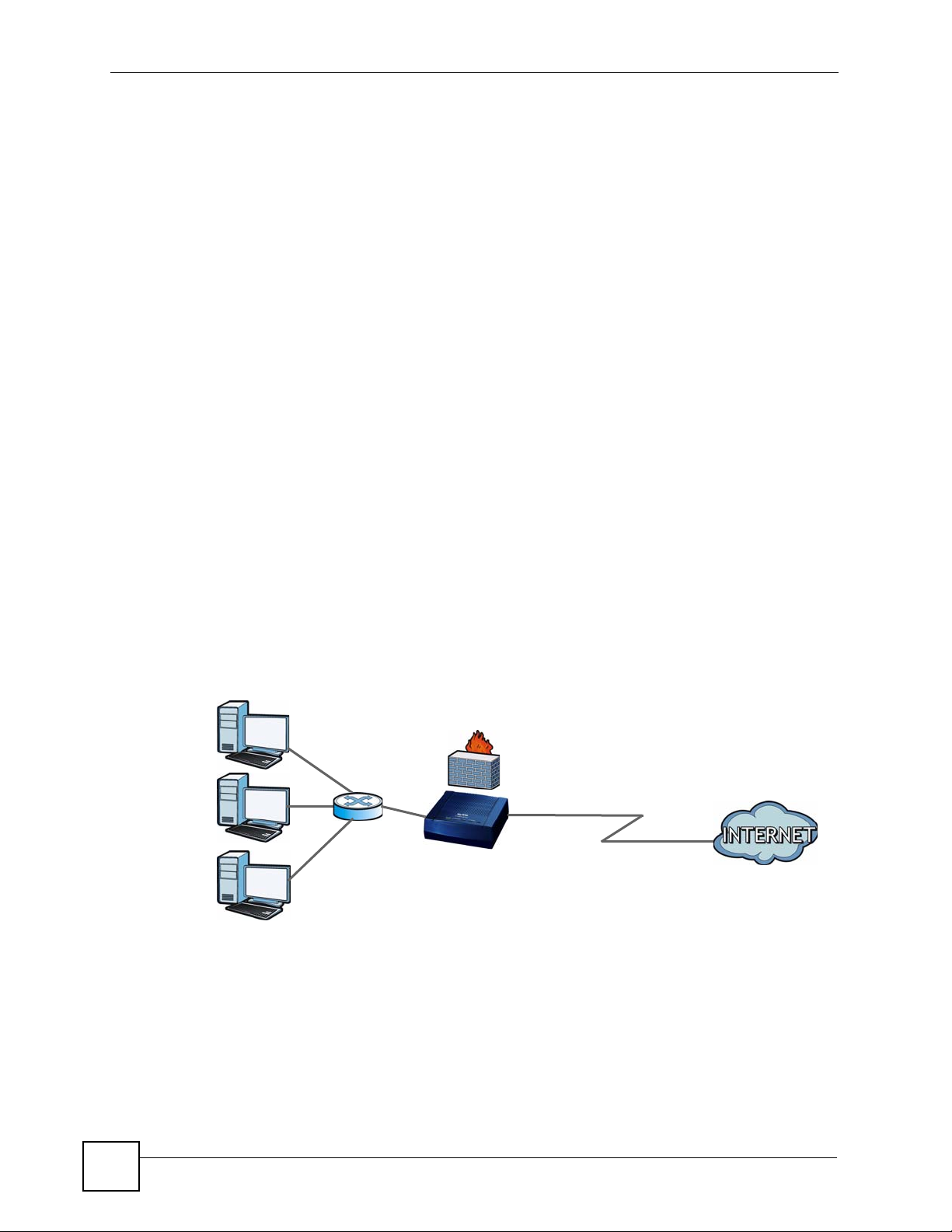
1.4.1 Internet Access
Your ZyXEL Device provides shared Internet access by connecting the DSL port to the DSL
or MODEM jack on a splitter or your telephone jack. Computers can connect to the ZyXEL
Device’s LAN ports.
Figure 1 ZyXEL Device’s Router Features
LAN
You can also configure firewall and content filtering on the ZyXEL Device for secure Internet
access. When the firewall is on, all incoming traffic from the Internet to your network is
blocked unless it is initiated from your network. This means that probes from the outside to
your network are not allowed, but you can safely browse the Internet and download files.
DSL
28
Use content filtering to block access to specific web sites, with URL’s containing keywords
that you specify. For example, you could block access to certain web sites for the kids.
P-660R-T1 v3 User’s Guide
Page 29
Use QoS to efficiently manage traffic on your network by giving priority to certain types of
traffic and/or to particular computers. For example, you could make sure that the ZyXEL
Device gives voice over Internet calls high priority, and/or limit bandwidth devoted to the
boss’s excessive file downloading.
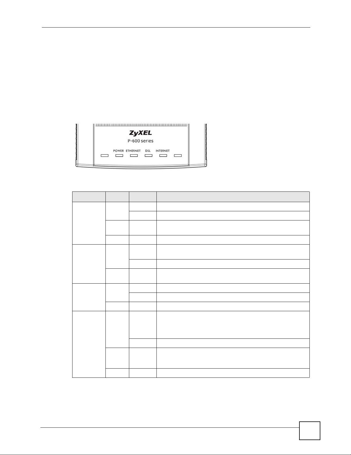
1.5 LEDs (Lights)
The following graphic displays the labels of the LEDs.
Figure 2 LEDs on the Top of the Device
None of the LEDs are on if the ZyXEL Device is not receiving power.
Table 1 LED Descriptions
LED COLOR STATUS DESCRIPTION
POWER Green On The ZyXEL Device is receiving power and ready for use.
Red On The ZyXEL Device detected an error while self-testing, or there is
ETHERNET Green On The ZyXEL Device has an Ethernet connection with a device on
DSL Green On The DSL line is up.
INTERNET Green On The ZyXEL Device has an IP connection but no traffic.
Red On The ZyXEL Device attempted to make an IP connection but
Chapter 1 Introducing the ZyXEL Device
Blinking The ZyXEL Device is self-testing.
a device malfunction.
Off The ZyXEL Device is not receiving power.
the Local Area Network (LAN).
Blinking The ZyXEL Device is sending/receiving data to /from the LAN.
Off The ZyXEL Device does not have an Ethernet connection with
the LAN.
Blinking The ZyXEL Device is initializing the DSL line.
Off The DSL line is down.
Your device has a WAN IP address (either static or assigned by a
DHCP server), PPP negotiation was successfully completed (if
used) and the DSL connection is up.
Blinking The ZyXEL Device is sending or receiving IP traffic.
failed. Possible causes are no response from a DHCP server, no
PPPoE response, PPPoE authentication failed.
Off The ZyXEL Device does not have an IP connection.
Refer to the Quick Start Guide for information on hardware connections.
P-660R-T1 v3 User’s Guide
29
Page 30

Chapter 1 Introducing the ZyXEL Device
1.6 The RESET Button
If you forget your password or cannot access the web configurator, you will need to use the
RESET button at the back of the device to reload the factory-default configuration file. This
means that you will lose all configurations that you had previously and the password will be
reset to “1234”.
1.6.1 Using the Reset Button
1 Make sure the POWER LED is on (not blinking).
2 To set the device back to the factory default settings, press the RESET button for ten
seconds or until the POWER LED begins to blink and then release it. When the
POWER LED begins to blink, the defaults have been restored and the device restarts.
30
P-660R-T1 v3 User’s Guide
Page 31

CHAPTER 2
Introducing the Web
Configurator
2.1 Overview
The web configurator is an HTML-based management interface that allows easy device setup
and management via Internet browser. Use Internet Explorer 6.0 and later or Netscape
Navigator 7.0 and later versions. The recommended screen resolution is 1024 by 768 pixels.
In order to use the web configurator you need to allow:
• Web browser pop-up windows from your device. Web pop-up blocking is enabled by
default in Windows XP SP (Service Pack) 2.
• JavaScripts (enabled by default).
• Java permissions (enabled by default).
See Appendix B on page 189 if you need to make sure these functions are allowed in Internet
Explorer.
2.1.1 Accessing the Web Configurator
1 Make sure your ZyXEL Device hardware is properly connected (refer to the Quick Start
Guide).
2 Launch your web browser.
3 Type "192.168.1.1" as the URL.
4 A login screen displays. To access the administrative web configurator and manage the
ZyXEL Device, enter the username (admin by default) and password (1234 by default)
in the login screen and click OK. If you have changed the password, enter your
password and click OK.
P-660R-T1 v3 User’s Guide
31
Page 32

Chapter 2 Introducing the Web Configurator
Figure 3 Login Screen
" For security reasons, the ZyXEL Device automatically logs you out if you do
not use the web configurator for five minutes (default). If this happens, log in
again.
2.2 Web Configurator Main Screen
Figure 4 Main Screen
A
B
32
As illustrated above, the main screen is divided into these parts:
• A - navigation panel
• B - main window
P-660R-T1 v3 User’s Guide
Page 33

Chapter 2 Introducing the Web Configurator
2.2.1 Navigation Panel
Use the menu items on the navigation panel to open screens to configure ZyXEL Device
features. The following tables describe each menu item.
Table 2 Navigation Panel Summary
LINK TAB FUNCTION
Status
Device Info This screen shows the ZyXEL Device’s general device and network status
System Log Use this screen to display your device’s logs.
Statistics Use this screen to display the statistics of the ZyXEL Device.
Quick Start
Quick Start Use this wizard to set up your Internet connection.
Interface Setup
Internet Internet Use this screen to configure ISP parameters, WAN IP address assignment
PVC Summary
Ta bl e
LAN LAN Use this screen to configure LAN TCP/IP and DHCP settings and other
DHCP IP Pool
Summary
Advanced Setup
Routing Routing Table
List
Static Route Use this screen to configure IP static routes to tell your device about
NAT NAT Use this screen to configure the NAT settings.
DMZ Use this screen to configure the DMZ settings.
Virtual Server Use this screen to forward incoming service requests to the server(s) on
IP Address
Mapping
QoS QoS Use this screen to enable QoS and traffic prioritizing and configure
QoS Settings
Summary
ADSL Use this screen to configure the ADSL settings on your ZyXEL Device.
Firewall Use this screen to activate/deactivate the firewall and/or SPI on your ZyXEL
Access Management
ACL Use this screen to determine which application can access which ZyXEL
Filter IP/MAC Filter Use this screen to to create IP/MAC filter rules.
Application Filter Use this screen to set the days and times for your device to perform content
information.
and other advanced properties.
Use this screen to display your PVC settings.
advanced properties.
Use this screen to display the IP and MAC addresses of the computers on
your LAN.
Use this screen to display the static routes on your ZyXEL Device.
networks beyond the directly connected remote nodes.
your local network.
Use this screen to change your ZyXEL Device’s address mapping settings.
bandwidth management on the WAN.
Use this screen to check the QoS rules and actions you configured for the
ZyXEL Device.
Device.
Device interface from which computers.
filtering.
P-660R-T1 v3 User’s Guide
33
Page 34

Chapter 2 Introducing the Web Configurator
Table 2 Navigation Panel Summary
LINK TAB FUNCTION
URL Filter Use this screen to allow or deny traffic from certain types of applications.
SNMP Use this screen to configure your ZyXEL Device’s settings for Simple
UPnP Use this screen to turn UPnP on or off.
DDNS This screen allows you to use a static hostname alias for a dynamic IP
CWMP Use this screen to have a management server manage the ZyXEL Device.
Maintenance
Administraton Use this screen to configure your device’s password.
Time Zone Use this screen to change your ZyXEL Device’s time and date.
Firmware Use this screen to manage configuration files and upload firmware to your
SysRestart This screen allows you to reboot the ZyXEL Device without turning the
Diagnostic Use this screen to test the connections to other devices.
Network Management Protocol management.
address.
device.
power off.
2.2.2 Main Window
The main window displays information and configuration fields. It is discussed in the rest of
this document.
Right after you log in, the Status screen is displayed. See Chapter 3 on page 37 for more
information about the Status screen.
34
P-660R-T1 v3 User’s Guide
Page 35

PART II
Device Information (37)
System Logs (39)
Traffic Statistics (41)
Status
35
Page 36

36
Page 37

CHAPTER 3
Device Information
3.1 Overview
Use the Device Info screen to look at the current status of the device, system resources, and
interfaces (LAN and WAN).
3.2 The Device Info Screen
Use this screen to view the status of the ZyXEL Device. Click Status > Device Info to open
the following screen.
Figure 5 Status > Device Information
P-660R-T1 v3 User’s Guide
37
Page 38

Chapter 3 Device Information
The following table describes the fields in this screen.
Table 3 Status > Device Information
LABEL DESCRIPTION
Device Information
Firmware
Versi on
MAC Address This is the MAC (Media Access Control) or Ethernet address unique to your
LAN
IP Address This is the current IP address of the ZyXEL Device in the LAN.
Subnet Mask This is the current subnet mask in the LAN.
DHCP Server This field displays what DHCP services the ZyXEL Device is providing to the LAN.
WAN
Virtual Circuit Use the drop-down list box to select a virtual circuit. The fields below display
Status This is the status of the WAN connection.
Connection
Type
IP Address This is the current IP address of the ZyXEL Device in the WAN, if applicable.
IP Subnet
Mask
Default
Gateway
DNS Server
NAT This field displays whether NAT is activated.
ADSL
ADSL
Firmware
Versi on
Line State This is the status of your ADSL connection.
Modulation This is the ADSL modulation of your ZyXEL Device.
Annex Mode This is the annex mode of your ZyXEL Device.
Downstream This is the downstream speed of your ZyXEL Device.
Upstream This is the upstream speed of your ZyXEL Device.
SNR Margin This is the Signal to Noise Ratio (SNR) margin. SNR represents the ratio of the
Line
Attenuation
Data Rate This is speed of data transfer on your ZyXEL Device.
This is the current version of the firmware inside the device. It also shows the date
the firmware version was created.
ZyXEL Device.
Choices are:
Enabled - The ZyXEL Device is a DHCP server in the LAN. It can assign IP
addresses to other computers in the LAN.
Relay - The ZyXEL Device acts as a surrogate DHCP server and relays DHCP
requests and responses between the remote server and the clients.
Disabled - The ZyXEL Device is not providing any DHCP services to the LAN.
information about the virtual circuit you choose.
This is the connection type supported by your ISP.
This is the current subnet mask in the WAN, if applicable.
This is the IP address of the default gateway, if applicable.
This is the current DNS server in the WAN, if applicable.
This is the current version of the device’s DSL modem code.
signal received to the system’s noise threshold. The higher the SNR number, the
better the line quality.
This is the difference (in dB) between the power received at the near-end and that
transmitted from the far-end.
38
P-660R-T1 v3 User’s Guide
Page 39

CHAPTER 4
System Logs
4.1 Overview
This chapter contains information about viewing the ZyXEL Device’s logs.
A log is a message about an event that occurred on your ZyXEL Device. For example, when
someone logs in to the ZyXEL Device.
4.2 The System Log Screen
Use this screen to see the logs for your ZyXEL Device. Click Status > System Log to open
the following screen.
Figure 6 Status > System Log
The following table describes the fields in this screen.
Table 4 Status > System Log
LABEL DESCRIPTION
System Log This field displays the log messages of your ZyXEL Device.
P-660R-T1 v3 User’s Guide
39
Page 40

Chapter 4 System Logs
Table 4 Status > System Log
LABEL DESCRIPTION
CLEAR LOG Click this to delete all the logs.
SAVE LOG Click this to save the logs in a text file.
40
P-660R-T1 v3 User’s Guide
Page 41

CHAPTER 5
Traffic Statistics
5.1 Overview
This chapter contains information about viewing traffic statistics of your ZyXEL Device.
5.2 The Statistics Screen
Use this screen to check the traffic statistics of your ZyXEL Device. Click Status > Statistics
to open the following screen. The screen varies depending on what type of port you selected in
the Interface field.
The following screen displays traffic statistics for the Ethernet port.
Figure 7 Status > Statistics (Ethernet)
The following table describes the labels in this screen.
Table 5 Status > Statistics (Ethernet)
LABEL DESCRIPTION
Interface Select Ethernet or ADSL to display traffic statistics on the port.
Transmit Statistics
Transmit Frames This field displays the number of transmitted frames on this port.
Transmit Multicast
Frames
Transmit total Bytes This field displays the number of bytes transmitted on this port.
Transmit Collision This field displays information on collisions while transmitting frames.
Transmit Error Frames This field displays the number of transmitted errors on this port.
Receive Statistics
Receive Frames This field displays the number of received frames on this port.
P-660R-T1 v3 User’s Guide
This field displays the number of good multicast frames transmitted.
41
Page 42
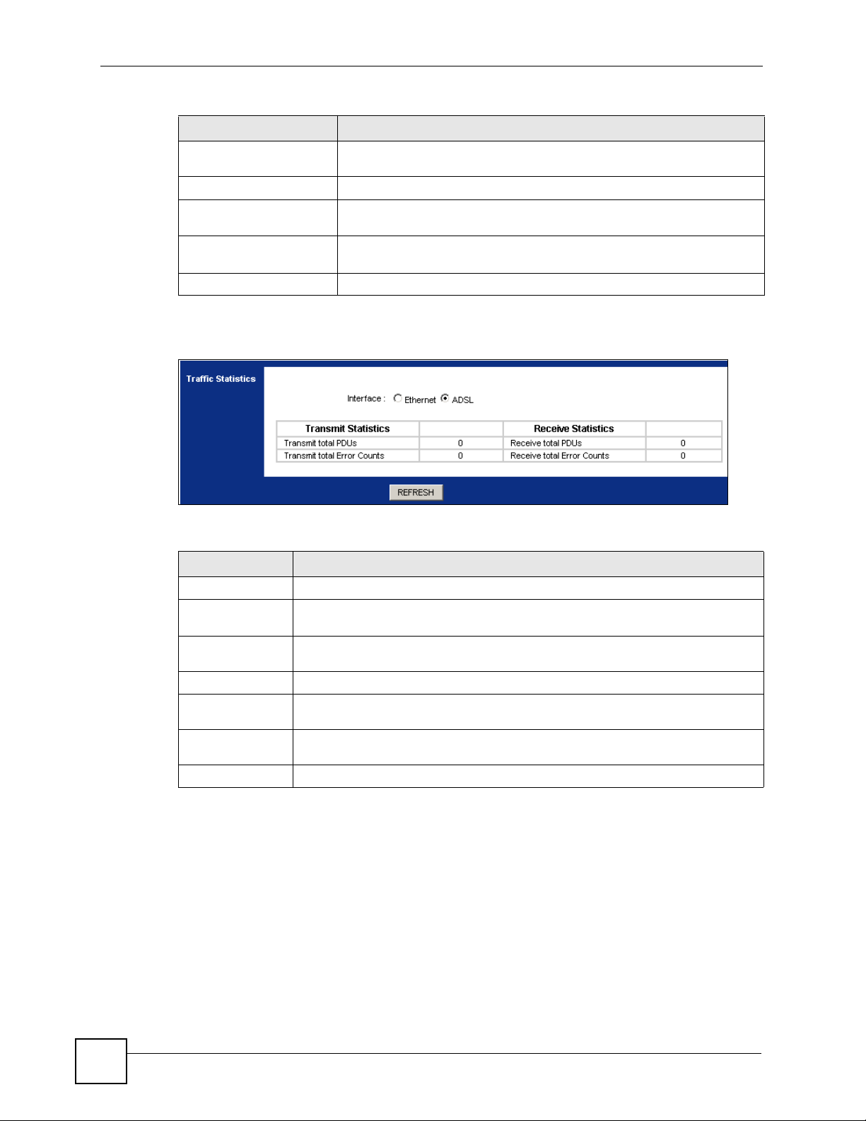
Chapter 5 Traffic Statistics
Table 5 Status > Statistics (Ethernet) (continued)
LABEL DESCRIPTION
Receive Multicast
Frames
Receive total Bytes This field displays the number of bytes received on this port.
Receive CRC errors This field displays the number of frames received with Cyclic Redundant
Receive Under-size
Frames
REFRESH Click this to update the screen.
The following screen displays traffic statitstics for the ADSL port.
Figure 8 Status > Statistics (ADSL)
This field displays the number of good multicast frames received.
Check (CRC) errors.
This field displays the number of received frames that were under-size
(shorter than 60 octets or greater than 1522 octets).
The following table describes the labels in this screen.
Table 6 Status > Statistics (ADSL)
LABEL DESCRIPTION
Transmit Statistics
Transmit total
PDUs
Transmit total
Error Counts
Receive Statistics
Receive total
PDUs
Receive total
Error Counts
REFRESH Click this to update the screen.
This field displays the amount of Protocol Data Units (PDUs) transmitted on this
port.
This field displays the number of error counts transmitted on this port.
This field displays the amount of PDUs received on this port.
This field displays the number of error counts received on this port.
42
P-660R-T1 v3 User’s Guide
Page 43

PART III
Quick Start Wizard
Quick Start Wizard (45)
43
Page 44

44
Page 45

CHAPTER 6
Quick Start Wizard
6.1 Overview
This chapter provides information on the Quick Start Wizard screens. Use the wizard screens
to configure your system for Internet access with the information given to you by your ISP.
" See the advanced menu chapters for background information on these fields.
6.2 Quick Start Wizard
1 After you enter the password to access the web configurator, click Quick Start > Quick
Start from the navigation panel to go to the wizard screens.
Figure 9 Access Quick Start Wizard
P-660R-T1 v3 User’s Guide
45
Page 46

Chapter 6 Quick Start Wizard
2 Click RUN WIZARD to configure the system for Internet access.
Figure 10 Run Wizard
3 The following screen summarizes the steps required to configure an Internet connection.
Click NEXT to begin the setup.
Figure 11 Wizard Summary
4 Enter a new password for accessing the web configurator or enter your old one if you
don’t want to change it. Type the new or old password in both fields and click NEXT.
Figure 12 Password
46
P-660R-T1 v3 User’s Guide
Page 47

Chapter 6 Quick Start Wizard
5 Select the time zone for your location and click NEXT.
Figure 13 Time Zone
6 Select the connection type supported by your ISP and click NEXT.
Figure 14 ISP Connection Type
7 The next wizard screen varies depending on what connection type you use. Configure
the fields and click NEXT to continue.
Figure 15 ISP Connection: Dynamic IP
P-660R-T1 v3 User’s Guide
47
Page 48

Chapter 6 Quick Start Wizard
The following table describes the fields in this screen.
Table 7 ISP Connection: Dynamic IP
LABEL DESCRIPTION
VPI Enter the VPI (Virtual Path Identifier) assigned to you. This field may already be
VCI Enter the VCI (Virtual Channel Identifier) assigned to you. This field may already be
Connection Type Select the multiplexing method used by your ISP from the drop-down list box.
BACK Click this to return to the previous screen without saving.
NEXT Click this to continue to the next wizard screen.
EXIT Click this to close the wizard screen without saving.
Figure 16 ISP Connection: Static IP Address
configured. VPI defines a virtual circuit. Refer to the appendix for more information.
configured. VCI defines a virtual circuit. Refer to the appendix for more information.
Available options are: 1483 Bridged IP LLC, 1483 Bridged IP VC-Mux, 1483
Routed IP LLC(IPoA) and 1483 Routed IP VC-Mux.
48
The following table describes the fields in this screen.
Table 8 ISP Connection: Static IP Address
LABEL DESCRIPTION
VPI Enter the VPI assigned to you. This field may already be configured. VPI defines a
VCI Enter the VCI assigned to you. This field may already be configured. VCI defines a
IP Address Type your ISP assigned IP address in this field.
Subnet mask Enter a subnet mask in dotted decimal notation.
ISP Gateway Specify a gateway IP address supplied by your ISP.
Connection
Type
BACK Click this to return to the previous screen without saving.
NEXT Click this to continue to the next wizard screen.
EXIT Click this to close the wizard screen without saving.
virtual circuit. Refer to the appendix for more information.
virtual circuit. Refer to the appendix for more information.
Refer to the appendix to calculate a subnet mask If you are implementing subnetting.
Select the multiplexing method used by your ISP from the drop-down list box.
Available options are: 1483 Bridged IP LLC, 1483 Bridged IP VC-Mux, 1483
Routed IP LLC(IPoA) and 1483 Routed IP VC-Mux.
P-660R-T1 v3 User’s Guide
Page 49

Chapter 6 Quick Start Wizard
Figure 17 ISP Connection: PPPoE/PPPoA
The following table describes the fields in this screen.
Table 9 ISP Connection: PPPoE/PPPoA
LABEL DESCRIPTION
Username Enter the username exactly as your ISP assigned. If assigned a name in the form
Password Enter the password associated with the above username.
VPI Enter the VPI assigned to you. This field may already be configured. VPI defines a
VCI Enter the VCI assigned to you. This field may already be configured. VCI defines a
Connection Type Select the multiplexing method used by your ISP from the drop-down list box.
BACK Click this to return to the previous screen without saving.
NEXT Click this to continue to the next wizard screen.
EXIT Click this to close the wizard screen without saving.
user@domain where domain identifies a service name, then enter both
components exactly as given.
virtual circuit. Refer to the appendix for more information.
virtual circuit. Refer to the appendix for more information.
Available options are: PPPoE LLC, PPPoE VC-Mux, PPPoA LLC and PPPoA
VC-Mux.
Figure 18 ISP Connection: Bridge Mode
P-660R-T1 v3 User’s Guide
49
Page 50

Chapter 6 Quick Start Wizard
The following table describes the fields in this screen.
Table 10 ISP Connection: Bridge Mode
LABEL DESCRIPTION
VPI Enter the VPI assigned to you. This field may already be configured. VPI defines a
VCI Enter the VCI assigned to you. This field may already be configured. VCI defines a
Connection
Type
BACK Click this to return to the previous screen without saving.
NEXT Click this to continue to the next wizard screen.
EXIT Click this to close the wizard screen without saving.
8 Click NEXT to save your changes and complete the setup.
Figure 19 Complete Quick Start
virtual circuit. Refer to the appendix for more information.
virtual circuit. Refer to the appendix for more information.
Select the multiplexing method used by your ISP from the drop-down list box.
Available options are: 1483 Bridged IP LLC and 1483 Bridged IP VC-Mux.
9 Launch your web browser and navigate to www.zyxel.com. Internet access is just the
beginning. Refer to the rest of this guide for more detailed information on the complete
range of ZyXEL Device features. If you cannot access the Internet, open the web
configurator again to confirm that the Internet settings you configured in the wizard
setup are correct.
50
P-660R-T1 v3 User’s Guide
Page 51

PART IV
Interface Setup
Internet Setup (53)
LAN Setup (67)
51
Page 52

52
Page 53

CHAPTER 7
Internet Setup
7.1 Overview
This chapter describes how to configure Wide Area Network (WAN) settings from the
Internet screens. Use these screens to configure your ZyXEL Device for Internet access.
A WAN connection is an outside connection to another network or the Internet. It connects
your private networks (such as a Local Area Network (LAN) and other networks, so that a
computer in one location can communicate with computers in other locations.
Figure 20 LAN and WAN
LAN
7.1.1 What You Can Do in the Internet Screens
• Use the Internet screen (Section 7.2 on page 55) to configure the WAN settings on the
ZyXEL Device for Internet access.
• Use the PVCs Summary screen (Section 7.2.5 on page 62) to display a summary table for
PVC settings.
7.1.2 What You Need to Know About ADSL Internet Access
Encapsulation Method
Encapsulation is used to include data from an upper layer protocol into a lower layer protocol.
To set up a WAN connection to the Internet, you need to use the same encapsulation method
used by your Internet Service Provider (ISP). If your ISP offers a dial-up Internet connection
using PPP over Ethernet (PPPoE) or PPPoA, they should also provide a username and
password (and service name) for user authentication.
WAN
P-660R-T1 v3 User’s Guide
53
Page 54

Chapter 7 Internet Setup
ADSL Terms
A Permanent Virtual Circuit (PVC) is the connection for your device to the ISP. You need a
Virtual Path Identifier (VPI) and a Virtual Channel Identifier (VCI) to identify a PVC.
Multiplexing is a way of carrying protocols on a PVC. Your ISP should supply you with all
this information.
WAN IP Address
The WAN IP address is an IP address for the ZyXEL Device, which makes it accessible from
an outside network. It is used by the ZyXEL Device to communicate with other devices in
other networks. It can be static (fixed) or dynamically assigned by the ISP each time the
ZyXEL Device tries to access the Internet.
If your ISP assigns you a static WAN IP address, they should also assign you the subnet mask
and DNS server IP address(es) (and a gateway IP address if you use the Ethernet or ENET
ENCAP encapsulation method).
ATM Qo S
Asynchronous Transfer Mode (ATM) is a LAN and WAN networking technology that
provides high-speed data transfer. ATM uses fixed-size packets of information called cells.
With ATM, a high QoS (Quality of Service) can be guaranteed. QoS is a service agreement
that guarantees certain speed even when the network is congested. ATM QoS is defined by the
Peak Cell Rate (PCR), Sustain Cell Rate (SCR) and Maximum Burst Size (MBS).
NAT
NAT (Network Address Translation - NAT, RFC 1631) is the translation of the IP address of a
host in a packet, for example, the source address of an outgoing packet, used within one
network to a different IP address known within another network.
Multicast
Traditionally, IP packets are transmitted in one of either two ways - Unicast (1 sender - 1
recipient) or Broadcast (1 sender - everybody on the network). Multicast delivers IP packets to
a group of hosts on the network - not everybody and not just one.
IGMP
Internet Group Multicast Protocol (IGMP) is a network-layer protocol used to establish
membership in a Multicast group - it is not used to carry user data. There are three versions of
IGMP. IGMP version 2 is an improvement over version 1, but IGMP version 1 is still in wide
use. IGMP version 3 supports source filtering, reporting or ignoring traffic from specific
source address to a particular host on the network.
Finding Out More
See Section 7.3 on page 63 for technical background information on WAN.
7.1.3 Before You Begin
54
You need to know your Internet access settings such as encapsulation and WAN IP address.
Get this information from your ISP.
P-660R-T1 v3 User’s Guide
Page 55

7.2 The Internet Screen
Use this screen to change your ZyXEL Device’s WAN settings. Click Interface Setup >
Internet. The screen differs by the encapsulation you select.
Figure 21 Interface Setup > Internet
Chapter 7 Internet Setup
The following table describes the labels in this screen.
Tabl e 11 Interface Setup > Internet
LABEL DESCRIPTION
ATM V C
Virtual Circuit Select the PVC you want to configure from the drop-down list box.
PVCs Summary Click this to display a summary table of the PVC settings on your ZyXEL Device.
Status Use this field to enable or disable the PVC.
VPI Virtual Path Identifier (VPI) defines a virtual circuit. Refer to the appendix for
VCI Virtual Channel Identifier (VCI) defines a virtual circuit. Enter the VCI assigned
QoS
P-660R-T1 v3 User’s Guide
See Section 7.2.5 on page 62 for more details.
more information. Enter the VPI assigned to you.
to you. Refer to the appendix for more information.
55
Page 56

Chapter 7 Internet Setup
Tabl e 11 Interface Setup > Internet (continued)
LABEL DESCRIPTION
ATM QoS Select CBR (Continuous Bit Rate) to specify fixed (always-on) bandwidth for
PCR Divide the DSL line rate (bps) by 424 (the size of an ATM cell) to find the Peak
SCR The Sustain Cell Rate (SCR) sets the average cell rate (long-term) that can be
MBS Maximum Burst Size (MBS) refers to the maximum number of cells that can be
Encapsulation Select the connection type supported by your ISP. The next fields vary
SAVE Click this to save your changes.
DELETE Click this to restore the PVC to default settings.
voice or data traffic. Select UBR (Unspecified Bit Rate) for applications that are
non-time sensitive, such as e-mail. Select rtVBR (real-time Variable Bit Rate) for
applications with bursty connections that require closely controlled delay and
delay variation. Select nrtVBR (non real-time Variable Bit Rate) for connections
that do not require closely controlled delay and delay variation.
Cell Rate (PCR). This is the maximum rate at which the sender can send cells.
Type the PCR in this field.
transmitted. Type the SCR, which must be less than the PCR. Note that system
default is 0 cells/sec.
sent at the peak rate. Type the MBS, which is less than 65535.
depending on what connection type you use. See the following sections for more
details.
7.2.1 Dynamic IP Address
In the Interface Setup > Internet screen, select Dynamic IP Address from the ISP field to
display the following screen.
Figure 22 Interface Setup > Internet (Dynamic IP)
56
P-660R-T1 v3 User’s Guide
Page 57

Chapter 7 Internet Setup
The following table describes the labels in this screen.
Table 12 Interface Setup > Internet (Dynamic IP)
LABEL DESCRIPTION
Encapsulation Select the method of multiplexing used by your ISP from the drop-down list box.
Bridge Interface This field is only available when you select 1483 Bridged IP LLC or 1483
NAT Use this field to enable or disable Network Address Translation (NAT).
Default Route Select Yes to direct traffic not listed in the routing table to the default gateway.
TCP MTU Option The Maximum Transmission Unit (MTU) defines the size of the largest packet
Dynamic Route RIP (Routing Information Protocol) allows a router to exchange routing
Direction Use this field to control how much routing information the ZyXEL Device sends
Multicast Multicast packets are sent to a group of computers on the LAN and are an
MAC Spoofing This field is only available when you select 1483 Bridged IP LLC or 1483
Available options are: 1483 Bridged IP LLC, 1483 Bridged IP VC-Mux, 1483
Routed IP LLC(IPoA) and 1483 Routed IP VC-Mux.
Bridged IP VC-Mux in the Encapsulation field.
Use this field to enable or disable the bridge mode. Activate the bridge mode
when your ISP provides you with more than one IP address and you want the
connected computers to get individual IP address from ISP’s DHCP server
directly.
Select No to drop traffic not listed in the routing table.
allowed on an interface or connection. Enter the MTU in this field.
information with other routers.
Select the RIP version from RIP1, RIP2-B and RIP2-M.
and receives on the subnet.
Select the RIP direction from None, Both, IN Only and OUT Only.
alternative to unicast packets (packets sent to one computer) and broadcast
packets (packets sent to every computer).
IGMP is a network-layer protocol used to establish membership in a multicast
group. The ZyXEL Device supports IGMP v1, IGMP v2 and IGMP v3. Select
Disabled to turn off the feature.
Bridged IP VC-Mux in the Encapsulation field.
Use this field to alter the MAC address so that the PVCs on the ZyXEL Device
can establish connections to the network.
P-660R-T1 v3 User’s Guide
57
Page 58

Chapter 7 Internet Setup
7.2.2 Static IP Address
In the Interface Setup > Internet screen, select Static IP Address from the ISP field to
display the following screen.
Figure 23 Interface Setup > Internet (Static IP)
The following table describes the labels in this screen.
Table 13 Interface Setup > Internet (Static IP)
LABEL DESCRIPTION
Encapsulation Select the method of multiplexing used by your ISP from the drop-down list box.
Available options are: 1483 Bridged IP LLC, 1483 Bridged IP VC-Mux, 1483
Routed IP LLC(IPoA) and 1483 Routed IP VC-Mux.
Static IP Address A static IP address is a fixed IP that your ISP gives you. Type your ISP assigned
IP address in the field.
IP Subnet Mask Enter a subnet mask in dotted decimal notation.
Gateway Specify a gateway IP address (supplied by your ISP).
Bridge Interface This field is only available when you select 1483 Bridged IP LLC or 1483
Bridged IP VC-Mux in the Encapsulation field.
Use this field to enable or disable the bridge mode. Activate the bridge mode
when your ISP provides you with more than one IP address and you want the
connected computers to get individual IP address from ISP’s DHCP server
directly.
NAT Use this field to enable or disable Network Address Translation (NAT).
Default Route Select Yes to direct traffic not listed in the routing table to the default gateway.
Select No to drop traffic not listed in the routing table.
TCP MTU Option The Maximum Transmission Unit (MTU) defines the size of the largest packet
allowed on an interface or connection. Enter the MTU in this field.
58
P-660R-T1 v3 User’s Guide
Page 59

Chapter 7 Internet Setup
Table 13 Interface Setup > Internet (Static IP) (continued)
LABEL DESCRIPTION
Dynamic Route RIP (Routing Information Protocol) allows a router to exchange routing
information with other routers.
Select the RIP version from RIP1, RIP2-B and RIP2-M.
Direction Use this field to control how much routing information the ZyXEL Device sends
and receives on the subnet.
Select the RIP direction from None, Both, IN Only and OUT Only.
Multicast Multicast packets are sent to a group of computers on the LAN and are an
alternative to unicast packets (packets sent to one computer) and broadcast
packets (packets sent to every computer).
IGMP is a network-layer protocol used to establish membership in a multicast
group. The ZyXEL Device supports IGMP v1, IGMP v2 and IGMP v3. Select
Disabled to turn off the feature.
MAC Spoofing This field is only available when you select 1483 Bridged IP LLC or 1483
Bridged IP VC-Mux in the Encapsulation field.
Use this field to alter the MAC address so that the PVCs on the ZyXEL Device
can establish connections to the network.
P-660R-T1 v3 User’s Guide
59
Page 60

Chapter 7 Internet Setup
7.2.3 PPPoA/PPPoE
In the Interface Setup > Internet screen, select PPPoA/PPPoE from the ISP field to display
the following screen.
Figure 24 Interface Setup > Internet (PPPoA/PPPoE)
60
The following table describes the labels in this screen.
Table 14 Interface Setup > Internet (PPPoA/PPPoE)
LABEL DESCRIPTION
PPPoE/PPPoA
Servicename Type the name of your service in this field.
Username Enter the username exactly as your ISP assigned. If assigned a name in the form
user@domain where domain identifies a service name, then enter both
components exactly as given.
Password Enter the password associated with the username above.
Encapsulation Select the method of multiplexing used by your ISP from the drop-down list box.
Available options are: PPPoE LLC, PPPoE VC-Mux, PPPoA LLC and PPPoA VC-
Mux.
P-660R-T1 v3 User’s Guide
Page 61

Chapter 7 Internet Setup
Table 14 Interface Setup > Internet (PPPoA/PPPoE) (continued)
LABEL DESCRIPTION
Bridge Interface This field is only available when you select PPPoE LLC or PPPoE VC-Mux in the
Encapsulation field.
Use this field to enable or disable the bridge mode. Activate the bridge mode when
your ISP provides you with more than one IP address and you want the connected
computers to get individual IP address from ISP’s DHCP server directly.
Connection Setting
Connection Select Always On (Recommended) when you want your connection up all the
time. The ZyXEL Device will try to bring up the connection automatically if it is
disconnected.
Select Connect On-Demand when you don't want the connection up all the time
and specify an idle time-out in minutes. The default setting is 0 minute, which
means the Internet session will not timeout.
Select Connect Manually to establish the connection only when you need it.
Note: Do not specify an always-on connection unless your
telephone company offers flat-rate service or you need a
constant connection and the cost is of no concern.
TCP MSS Option The TCP Maximum Segment Size (MSS) defines the size of the largest packet
allowed on an interface or connection. Enter the TCP MSS in this field. In general,
the TCP MSS is 1452.
IP Address
Get IP Address Select the type of IP address provided by your ISP. A static IP address is a fixed IP
Static IP Address Type your ISP assigned IP address in the field.
IP Subnet Mask Enter a subnet mask in dotted decimal notation.
Gateway Specify a gateway IP address (supplied by your ISP).
NAT Use this field to enable or disable Network Address Translation (NAT).
Default Route Select Yes to direct traffic not listed in the routing table to the default gateway.
TCP MTU Option The Maximum Transmission Unit (MTU) defines the size of the largest packet
Dynamic Route RIP (Routing Information Protocol) allows a router to exchange routing information
Direction Use this field to control how much routing information the ZyXEL Device sends and
Multicast Multicast packets are sent to a group of computers on the LAN and are an
MAC Spoofing This field is only available when you select 1483 Bridged IP LLC or 1483 Bridged
that your ISP gives you. A dynamic IP address is not fixed; the ISP assigns you a
different one each time you connect to the Internet.
Select No to drop traffic not listed in the routing table.
allowed on an interface or connection. Enter the MTU in this field.
with other routers.
Select the RIP version from RIP1, RIP2-B and RIP2-M.
receives on the subnet.
Select the RIP direction from None, Both, IN Only and OUT Only.
alternative to unicast packets (packets sent to one computer) and broadcast
packets (packets sent to every computer).
IGMP is a network-layer protocol used to establish membership in a multicast
group. The ZyXEL Device supports IGMP v1, IGMP v2 and IGMP v3. Select
Disabled to turn off the feature.
IP VC-Mux in the Encapsulation field.
Use this field to alter the MAC address so that the PVCs on the ZyXEL Device can
establish connections to the network.
P-660R-T1 v3 User’s Guide
61
Page 62

Chapter 7 Internet Setup
7.2.4 Bridge Mode
In the Interface Setup > Internet screen, select Bridge Mode from the ISP field to display
the following screen.
Figure 25 Interface Setup > Internet (Bridge)
The following table describes the labels in this screen.
Table 15 Interface Setup > Internet (Bridge)
LABEL DESCRIPTION
Encapsulation Select the method of multiplexing used by your ISP from the drop-down list box.
Available options are: 1483 Bridged IP LLC and 1483 Bridged IP VC-Mux.
7.2.5 The PVCs Summary Screen
Use this field to check your PVC settings. In the Interface Setup > Internet screen, click
PVCs Summary in the Virtual Circuit field to display the following screen.
Figure 26 Interface Setup > PVCs Summary
The following table describes the labels in this screen.
Table 16 Interface Setup > PVCs Summary
LABEL DESCRIPTION
# This field displays the index number for the corresponding PVC.
Active This field displays whether the PVC is activated.
VPI This field displays the VPI value.
VCI This field displays the VCI value.
62
P-660R-T1 v3 User’s Guide
Page 63

Table 16 Interface Setup > PVCs Summary (continued)
LABEL DESCRIPTION
ENCAP This field displays the type of encapsulation.
Mux This field displays the multiplexing method.
IP Address This field displays the type of IP address.
Status This field displays the connection status of the PVC.
7.3 WAN Technical Reference
This section provides some technical background information about the topics covered in this
chapter.
7.3.1 Encapsulation
Be sure to use the encapsulation method required by your ISP. The ZyXEL Device supports
the following methods.
Chapter 7 Internet Setup
PPP over Ethernet
The ZyXEL Device supports Point-to-Point Protocol over Ethernet (PPPoE). PPPoE is an
IETF Draft standard (RFC 2516) specifying how a personal computer (PC) interacts with a
broadband modem (DSL, cable, wireless, etc.) connection. The PPPoE option is for a dial-up
connection using PPPoE.
For the service provider, PPPoE offers an access and authentication method that works with
existing access control systems (for example RADIUS).
One of the benefits of PPPoE is the ability to let you access one of multiple network services,
a function known as dynamic service selection. This enables the service provider to easily
create and offer new IP services for individuals.
Operationally, PPPoE saves significant effort for both you and the ISP or carrier, as it requires
no specific configuration of the broadband modem at the customer site.
By implementing PPPoE directly on the ZyXEL Device (rather than individual computers),
the computers on the LAN do not need PPPoE software installed, since the ZyXEL Device
does that part of the task. Furthermore, with NAT, all of the LANs’ computers will have
access.
PPPoA
PPPoA stands for Point to Point Protocol over ATM Adaptation Layer 5 (AAL5). A PPPoA
connection functions like a dial-up Internet connection. The ZyXEL Device encapsulates the
PPP session based on RFC1483 and sends it through an ATM PVC (Permanent Virtual
Circuit) to the Internet Service Provider’s (ISP) DSLAM (Digital Subscriber Line (DSL)
Access Multiplexer). Please refer to RFC 2364 for more information on PPPoA. Refer to RFC
1661 for more information on PPP.
P-660R-T1 v3 User’s Guide
63
Page 64

Chapter 7 Internet Setup
RFC 1483
RFC 1483 describes two methods for Multiprotocol Encapsulation over ATM Adaptation
Layer 5 (AAL5). The first method allows multiplexing of multiple protocols over a single
ATM virtual circuit (LLC-based multiplexing) and the second method assumes that each
protocol is carried over a separate ATM virtual circuit (VC-based multiplexing). Please refer
to RFC 1483 for more detailed information.
7.3.2 Multiplexing
There are two conventions to identify what protocols the virtual circuit (VC) is carrying. Be
sure to use the multiplexing method required by your ISP.
VC-based Multiplexing
In this case, by prior mutual agreement, each protocol is assigned to a specific virtual circuit;
for example, VC1 carries IP, etc. VC-based multiplexing may be dominant in environments
where dynamic creation of large numbers of ATM VCs is fast and economical.
LLC-based Multiplexing
In this case one VC carries multiple protocols with protocol identifying information being
contained in each packet header. Despite the extra bandwidth and processing overhead, this
method may be advantageous if it is not practical to have a separate VC for each carried
protocol, for example, if charging heavily depends on the number of simultaneous VCs.
7.3.3 VPI and VCI
Be sure to use the correct Virtual Path Identifier (VPI) and Virtual Channel Identifier (VCI)
numbers assigned to you. The valid range for the VPI is 0 to 255 and for the VCI is 32 to
65535 (0 to 31 is reserved for local management of ATM traffic). Please see the appendix for
more information.
7.3.4 IP Address Assignment
A static IP is a fixed IP that your ISP gives you. A dynamic IP is not fixed; the ISP assigns you
a different one each time. However the encapsulation method assigned influences your choices
for IP address.
IP Assignment with PPPoA or PPPoE Encapsulation
If you have a dynamic IP, then the IP Address and Gateway IP Address fields are not
applicable (N/A). If you have a static IP, then you only need to fill in the IP Address field and
not the Gateway IP Address field.
IP Assignment with RFC 1483 Encapsulation
In this case the IP address assignment must be static.
64
P-660R-T1 v3 User’s Guide
Page 65

7.3.5 Always-On Connection (PPP)
An always-on connection is a dial-up line where the connection is always up regardless of
traffic demand. The ZyXEL Device does two things when you specify an always-on
connection. The first is that idle timeout is disabled. The second is that the ZyXEL Device will
try to bring up the connection when turned on and whenever the connection is down. An
always-on connection can be very expensive for obvious reasons.
Do not specify an always-on connection unless your telephone company offers flat-rate
service or you need a constant connection and the cost is of no concern.
7.3.6 ATM QoS
ATM QoS is an agreement between the carrier and the subscriber to regulate the average rate
and fluctuations of data transmission over an ATM network. This agreement helps eliminate
congestion, which is important for transmission of real time data such as audio and video
connections.
Peak Cell Rate (PCR) is the maximum rate at which the sender can send cells. This parameter
may be lower (but not higher) than the maximum line speed. 1 ATM cell is 53 bytes (424 bits),
so a maximum speed of 832Kbps gives a maximum PCR of 1962 cells/sec. This rate is not
guaranteed because it is dependent on the line speed.
Chapter 7 Internet Setup
Sustained Cell Rate (SCR) is the mean cell rate of each bursty traffic source. It specifies the
maximum average rate at which cells can be sent over the virtual connection. SCR may not be
greater than the PCR.
Maximum Burst Size (MBS) is the maximum number of cells that can be sent at the PCR.
After MBS is reached, cell rates fall below SCR until cell rate averages to the SCR again. At
this time, more cells (up to the MBS) can be sent at the PCR again.
If the PCR, SCR or MBS is set to the default of "0", the system will assign a maximum value
that correlates to your upstream line rate.
The following figure illustrates the relationship between PCR, SCR and MBS.
Figure 27 Example of ATM OoS
P-660R-T1 v3 User’s Guide
65
Page 66

Chapter 7 Internet Setup
7.3.7 ATM Traffic Classes
These are the basic ATM traffic classes defined by the ATM Forum Traffic Management 4.0
Specification.
Constant Bit Rate (CBR)
Constant Bit Rate (CBR) provides fixed bandwidth that is always available even if no data is
being sent. CBR traffic is generally time-sensitive (doesn't tolerate delay). CBR is used for
connections that continuously require a specific amount of bandwidth. A PCR is specified and
if traffic exceeds this rate, cells may be dropped. Examples of connections that need CBR
would be high-resolution video and voice.
Variable Bit Rate (VBR)
The Variable Bit Rate (VBR) ATM traffic class is used with bursty connections. Connections
that use the Variable Bit Rate (VBR) traffic class can be grouped into real time (VBR-RT) or
non-real time (VBR-nRT) connections.
The VBR-RT (real-time Variable Bit Rate) type is used with bursty connections that require
closely controlled delay and delay variation. It also provides a fixed amount of bandwidth (a
PCR is specified) but is only available when data is being sent. An example of an VBR-RT
connection would be video conferencing. Video conferencing requires real-time data transfers
and the bandwidth requirement varies in proportion to the video image's changing dynamics.
The VBR-nRT (non real-time Variable Bit Rate) type is used with bursty connections that do
not require closely controlled delay and delay variation. It is commonly used for "bursty"
traffic typical on LANs. PCR and MBS define the burst levels, SCR defines the minimum
level. An example of an VBR-nRT connection would be non-time sensitive data file transfers.
Unspecified Bit Rate (UBR)
The Unspecified Bit Rate (UBR) ATM traffic class is for bursty data transfers. However, UBR
doesn't guarantee any bandwidth and only delivers traffic when the network has spare
bandwidth. An example application is background file transfer.
66
P-660R-T1 v3 User’s Guide
Page 67

CHAPTER 8
LAN Setup
8.1 Overview
A Local Area Network (LAN) is a shared communication system to which many networking
devices are connected. It is usually located in one area such as a building or floor of a building.
Use the LAN screen to help you configure a LAN DHCP server and manage IP addresses.
LAN
DSL
8.1.1 What You Can Do in the LAN Screens
• Use the LAN screen (Section 8.2 on page 68) to set the LAN IP address and subnet mask
of your ZyXEL device. You can also edit your ZyXEL Device's RIP, multicast and DHCP
settings from this screen.
• Use the DHCP IP Pool Summary screen (Section 8.2.1 on page 70) to check the IP and
MAC addresses of the computers on your LAN.
8.1.2 What You Need To Know About LAN
IP Address
IP addresses identify individual devices on a network. Every networking device (including
computers, servers, routers, printers, etc.) needs an IP address to communicate across the
network. These networking devices are also known as hosts.
Subnet Mask
Subnet masks determine the maximum number of possible hosts on a network. You can also
use subnet masks to divide one network into multiple sub-networks.
P-660R-T1 v3 User’s Guide
67
Page 68

Chapter 8 LAN Setup
DHCP
A DHCP (Dynamic Host Configuration Protocol) server can assign your ZyXEL Device an IP
address, subnet mask, DNS and other routing information when it's turned on.
RIP
RIP (Routing Information Protocol) allows a router to exchange routing information with
other routers.
Multicast
Traditionally, IP packets are transmitted in one of either two ways - Unicast (1 sender - 1
recipient) or Broadcast (1 sender - everybody on the network). Multicast delivers IP packets to
a group of hosts on the network - not everybody and not just 1.
IGMP
IGMP (Internet Group Multicast Protocol) is a network-layer protocol used to establish
membership in a Multicast group - it is not used to carry user data. There are three versions of
IGMP. IGMP version 2 is an improvement over version 1, but IGMP version 1 is still in wide
use. IGMP version 3 supports source filtering, reporting or ignoring traffic from specific
source address to a particular host on the network.
DNS
DNS (Domain Name System) is for mapping a domain name to its corresponding IP address
and vice versa. The DNS server is extremely important because without it, you must know the
IP address of a networking device before you can access it.
Finding Out More
See Section 8.3 on page 71 for technical background information on LANs.
8.2 The LAN Screen
Use this screen to configure your LAN settings. Click Interface Setup > LAN to display the
following screen.
Follow these steps to configure your LAN settings.
1 Enter an IP address into the IP Address field. The IP address must be in dotted decimal
notation. This will become the IP address of your ZyXEL Device.
2 Enter the IP subnet mask into the IP Subnet Mask field. Unless instructed otherwise it
is best to leave this alone, the configurator will automatically compute a subnet mask
based upon the IP address you entered.
3 Click SAVE to save your settings.
68
P-660R-T1 v3 User’s Guide
Page 69

Chapter 8 LAN Setup
Figure 28 Interface Setup > LAN
The following table describes the fields in this screen.
Table 17 Interface Setup > LAN
LABEL DESCRIPTION
Router Local IP
IP Address Enter the LAN IP address you want to assign to your ZyXEL Device in dotted
IP Subnet Mask Type the subnet mask of your network in dotted decimal notation, for example
Dynamic Route RIP (Routing Information Protocol) allows a router to exchange routing
Direction Use this field to control how much routing information the ZyXEL Device sends
Multicast Multicast packets are sent to a group of computers on the LAN and are an
DHCP
DHCP If set to Enabled, your ZyXEL Device can assign IP addresses, an IP default
DHCP Server
Starting IP Address This field specifies the first of the contiguous addresses in the IP address pool.
decimal notation, for example, 192.168.1.1 (factory default).
255.255.255.0 (factory default). Your ZyXEL Device automatically computes the
subnet mask based on the IP Address you enter, so do not change this field
unless you are instructed to do so.
information with other routers.
Select the RIP version from RIP1, RIP2-B and RIP2-M.
and receives on the subnet.
Select the RIP direction from None, Both, IN Only and OUT Only.
alternative to unicast packets (packets sent to one computer) and broadcast
packets (packets sent to every computer).
IGMP is a network-layer protocol used to establish membership in a multicast
group. The ZyXEL Device supports IGMP v1, IGMP v2 and IGMP v3. Select
Disabled to turn off the feature.
gateway and DNS servers to operating systems that support the DHCP client.
If set to Disabled, the DHCP server will be disabled.
If set to Relay, the ZyXEL Device acts as a surrogate DHCP server and relays
DHCP requests and responses between the remote server and the clients.
P-660R-T1 v3 User’s Guide
69
Page 70

Chapter 8 LAN Setup
Table 17 Interface Setup > LAN
LABEL DESCRIPTION
Current Pool
Summary
IP Pool Count This field specifies the size, or count of the IP address pool.
Lease Time This is the period of time DHCP-assigned addresses is used.
DNS
DNS Relay Select Auto Discovered DNS Server Only if your ISP dynamically assigns DNS
Primary DNS
Server
Secondary DNS
Server
DHCP Server IP for
Relay Agent
SAVE Click this to save your changes.
CANCEL Click this to restore your previously saved settings.
Click this to display a summary table for the IP address pool. See Section 8.2.1
on page 70 for more details.
The ZyXEL Device is pre-configured with a pool of IP addresses for the DHCP
clients (DHCP Pool). See the product specifications in the appendices. Do not
assign static IP addresses from the DHCP pool to your LAN computers.
DHCP automatically assigns IP addresses to clients when they log in. DHCP
centralizes IP address management on central computers that run the DHCP
server program. DHCP leases addresses, for a period of time, which means that
past addresses are “recycled” and made available for future reassignment to
other systems.
server information (and the ZyXEL Device's WAN IP address).
Select User Discovered DNS Server Only if you have the IP address of a DNS
server. You have to specify the primary and secondary DNS servers in the
following fields.
Enter the IP address for the primary DNS server.
Enter the IP address for the secondary DNS server.
This field is only available when you select Relay in the DNS Relay field. Enter
the IP address of the actual remote DHCP server in this field.
8.2.1 The DHCP IP Pool Summary Screen
This table allows you to see the IP and Media Access Control (MAC) addresses of individual
computers on your LAN. In the Interface Setup > LAN screen, click the Current Pool
Summary button to open the following screen.
Figure 29 Interface Setup > LAN > DHCP IP Pool Summary
70
P-660R-T1 v3 User’s Guide
Page 71

The following table describes the labels in this screen.
Table 18 Interface Setup > LAN > DHCP IP Pool Summary
LABEL DESCRIPTION
Host Name This field displays the name of a computer that receives an IP address from the
ZyXEL Device.
IP Address This field displays the IP address of a computer that receives an IP address
from the ZyXEL Device.
MAC Address This field displays the MAC address of a computer that receives an IP address
from the ZyXEL Device.
8.3 LAN Technical Reference
This section provides some technical background information about the topics covered in this
chapter.
8.3.1 LANs, WANs and the ZyXEL Device
The actual physical connection determines whether the ZyXEL Device ports are LAN or
WAN ports. There are two separate IP networks, one inside the LAN network and the other
outside the WAN network as shown next.
Chapter 8 LAN Setup
Figure 30 LAN and WAN IP Addresses
LAN
8.3.2 DHCP Setup
DHCP (Dynamic Host Configuration Protocol, RFC 2131 and RFC 2132) allows individual
clients to obtain TCP/IP configuration at start-up from a server. You can configure the ZyXEL
Device as a DHCP server or disable it. When configured as a server, the ZyXEL Device
provides the TCP/IP configuration for the clients. If you turn DHCP service off, you must
have another DHCP server on your LAN, or else the computer must be manually configured.
WAN
P-660R-T1 v3 User’s Guide
71
Page 72

Chapter 8 LAN Setup
8.3.3 DNS Server Addresses
DNS (Domain Name System) maps a domain name to its corresponding IP address and vice
versa. The DNS server is extremely important because without it, you must know the IP
address of a computer before you can access it. The DNS server addresses you enter when you
set up DHCP are passed to the client machines along with the assigned IP address and subnet
mask.
There are two ways that an ISP disseminates the DNS server addresses.
• The ISP tells you the DNS server addresses, usually in the form of an information sheet,
when you sign up. If your ISP gives you DNS server addresses, enter them in the Primary
and Secondary DNS Server fields.
• Some ISPs choose to disseminate the DNS server addresses using the DNS server
extensions of IPCP (IP Control Protocol) after the connection is up. If your ISP did not
give you explicit DNS servers, chances are the DNS servers are conveyed through IPCP
negotiation. The ZyXEL Device supports the IPCP DNS server extensions through the
DNS proxy feature.
If the DHCP is set to Relay, the ZyXEL Device tells the DHCP clients that it itself is the
DNS server. When a computer sends a DNS query to the ZyXEL Device, the ZyXEL
Device acts as a DNS proxy and forwards the query to the real DNS server learned
through IPCP and relays the response back to the computer.
Please note that DNS proxy works only when the ISP uses the IPCP DNS server
extensions. It does not mean you can leave the DNS servers out of the DHCP setup under
all circumstances. If your ISP gives you explicit DNS servers, make sure that you enter
their IP addresses.
8.3.4 LAN TCP/IP
The ZyXEL Device has built-in DHCP server capability that assigns IP addresses and DNS
servers to systems that support DHCP client capability.
IP Address and Subnet Mask
Similar to the way houses on a street share a common street name, so too do computers on a
LAN share one common network number.
Where you obtain your network number depends on your particular situation. If the ISP or
your network administrator assigns you a block of registered IP addresses, follow their
instructions in selecting the IP addresses and the subnet mask.
If the ISP did not explicitly give you an IP network number, then most likely you have a single
user account and the ISP will assign you a dynamic IP address when the connection is
established. If this is the case, it is recommended that you select a network number from
192.168.0.0 to 192.168.255.0 and you must enable the Network Address Translation (NAT)
feature of the ZyXEL Device. The Internet Assigned Number Authority (IANA) reserved this
block of addresses specifically for private use; please do not use any other number unless you
are told otherwise. Let's say you select 192.168.1.0 as the network number; which covers 254
individual addresses, from 192.168.1.1 to 192.168.1.254 (zero and 255 are reserved). In other
words, the first three numbers specify the network number while the last number identifies an
individual computer on that network.
72
P-660R-T1 v3 User’s Guide
Page 73

Chapter 8 LAN Setup
Once you have decided on the network number, pick an IP address that is easy to remember,
for instance, 192.168.1.1, for your ZyXEL Device, but make sure that no other device on your
network is using that IP address.
The subnet mask specifies the network number portion of an IP address. Your ZyXEL Device
will compute the subnet mask automatically based on the IP address that you entered. You
don't need to change the subnet mask computed by the ZyXEL Device unless you are
instructed to do otherwise.
Private IP Addresses
Every machine on the Internet must have a unique address. If your networks are isolated from
the Internet, for example, only between your two branch offices, you can assign any IP
addresses to the hosts without problems. However, the Internet Assigned Numbers Authority
(IANA) has reserved the following three blocks of IP addresses specifically for private
networks:
• 10.0.0.0 — 10.255.255.255
• 172.16.0.0 — 172.31.255.255
• 192.168.0.0 — 192.168.255.255
You can obtain your IP address from the IANA, from an ISP or it can be assigned from a
private network. If you belong to a small organization and your Internet access is through an
ISP, the ISP can provide you with the Internet addresses for your local networks. On the other
hand, if you are part of a much larger organization, you should consult your network
administrator for the appropriate IP addresses.
" Regardless of your particular situation, do not create an arbitrary IP address;
always follow the guidelines above. For more information on address
assignment, please refer to RFC 1597, “Address Allocation for Private
Internets” and RFC 1466, “Guidelines for Management of IP Address Space”.
8.3.5 RIP Setup
RIP (Routing Information Protocol) allows a router to exchange routing information with
other routers. The RIP Direction field controls the sending and receiving of RIP packets.
When set to:
• Both - the ZyXEL Device will broadcast its routing table periodically and incorporate the
RIP information that it receives.
• In Only - the ZyXEL Device will not send any RIP packets but will accept all RIP packets
received.
• Out Only - the ZyXEL Device will send out RIP packets but will not accept any RIP
packets received.
• None - the ZyXEL Device will not send any RIP packets and will ignore any RIP packets
received.
P-660R-T1 v3 User’s Guide
73
Page 74

Chapter 8 LAN Setup
The Version field controls the format and the broadcasting method of the RIP packets that the
ZyXEL Device sends (it recognizes both formats when receiving). RIP-1 is universally
supported; but RIP-2 carries more information. RIP-1 is probably adequate for most networks,
unless you have an unusual network topology.
Both RIP-2B and RIP-2M sends the routing data in RIP-2 format; the difference being that
RIP-2B uses subnet broadcasting while RIP-2M uses multicasting.
8.3.6 Multicast
Traditionally, IP packets are transmitted in one of either two ways - Unicast (1 sender - 1
recipient) or Broadcast (1 sender - everybody on the network). Multicast delivers IP packets to
a group of hosts on the network - not everybody and not just 1.
IGMP (Internet Group Multicast Protocol) is a network-layer protocol used to establish
membership in a Multicast group - it is not used to carry user data. IGMP version 2 (RFC
2236) is an improvement over version 1 (RFC 1112) but IGMP version 1 is still in wide use.
IGMP version 3 supports source filtering, reporting or ignoring traffic from specific source
address to a particular host on the network. If you would like to read more detailed information
about interoperability between IGMP version 2 and version 1, please see sections 4 and 5 of
RFC 2236. The class D IP address is used to identify host groups and can be in the range
224.0.0.0 to 239.255.255.255. The address 224.0.0.0 is not assigned to any group and is used
by IP multicast computers. The address 224.0.0.1 is used for query messages and is assigned
to the permanent group of all IP hosts (including gateways). All hosts must join the 224.0.0.1
group in order to participate in IGMP. The address 224.0.0.2 is assigned to the multicast
routers group.
The ZyXEL Device supports IGMP version 1 (IGMP-v1), IGMP version 2 (IGMP-v2) and
IGMP version 3 (IGMP-v3). At start up, the ZyXEL Device queries all directly connected
networks to gather group membership. After that, the ZyXEL Device periodically updates this
information. IP multicasting can be enabled/disabled on the ZyXEL Device LAN and/or WAN
interfaces in the web configurator (LAN; WA N ). Select None to disable IP multicasting on
these interfaces.
74
P-660R-T1 v3 User’s Guide
Page 75

PART V
Advanced Setup
Static Route (77)
Network Address Translation (NAT) (81)
Quality of Service (QoS) (91)
ADSL (99)
Firewall (101)
75
Page 76

76
Page 77

CHAPTER 9
Static Route
9.1 Overview
The ZyXEL Device usually uses the default gateway to route outbound traffic from computers
on the LAN to the Internet. To have the ZyXEL Device send data to devices not reachable
through the default gateway, use static routes.
For example, the next figure shows a computer (A) connected to the ZyXEL Device’s LAN
interface. The ZyXEL Device routes most traffic from A to the Internet through the ZyXEL
Device’s default gateway (R1). You create one static route to connect to services offered by
your ISP behind router R2.
Figure 31 Example of Static Routing Topology
R1
A
LAN
9.1.1 What You Can Do in the Static Route Screens
• Use the Routing Table List screen (Section 9.2 on page 78) to view static routes on the
ZyXEL Device.
• Use the Static Route screen (Section 9.2.1 on page 78) to add or edit IP static routes on
the ZyXEL Device.
WAN
R2
P-660R-T1 v3 User’s Guide
77
Page 78

Chapter 9 Static Route
9.2 The Routing Table List Screen
Use this screen to view the static route rules. Click Advanced Setup > Routing to display the
following screen.
Figure 32 Advanced Setup > Routing Table List
The following table describes the labels in this screen.
Table 19 Advanced Setup > Routing Table List
LABEL DESCRIPTION
# This is the number of an individual static route.
Dest IP This parameter specifies the IP network address of the final destination. Routing is
always based on network number.
Mask This parameter specifies the IP network subnet mask of the final destination.
Gateway IP This is the IP address of the gateway. The gateway is a router or switch on the same
network segment as the device's LAN or WAN port. The gateway helps forward
packets to their destinations.
Metric This field displays the priority of each route on the ZyXEL Device.
Device This is the name that describes or identifies this route.
Use This is the number of times the route was used.
Edit Click this to go to the screen where you can set up a static route on the ZyXEL
Device. You cannot edit the default routes.
Drop Click this to remove a static route from the ZyXEL Device. You cannot delete the
default routes.
ADD ROUTE Click this to add a new static route on the ZyXEL Device.
9.2.1 The Static Route Screen
Use this screen to configure the required information for a static route. Select a static route
index number and click Edit, or click the ADD ROUTE button in the Routing Table List
screen. The screen shown next appears.
Figure 33 Advanced > Routing > Static Route
78
P-660R-T1 v3 User’s Guide
Page 79

Chapter 9 Static Route
The following table describes the labels in this screen.
Table 20 Advanced > Static Route: Edit
LABEL DESCRIPTION
Destination IP
Address
IP Subnet Mask Enter the IP subnet mask in this field.
Gateway IP
Address
Metric This field sets this route's priority among the routes the ZyXEL Device uses.
Announced in
RIP
SAVE Click this to save your changes.
DELETE Click this to remove the static route.
BACK Click this to return to the previous screen without saving.
CANCEL Click this to restore your previously saved settings.
This parameter specifies the IP network address of the final destination. Routing is
always based on network number. If you need to specify a route to a single host,
use a subnet mask of 255.255.255.255 in the subnet mask field to force the network
number to be identical to the host ID.
You can set the static route using a gateway IP address or a remote node.
Enter the IP address of the gateway. The gateway is a router or switch on the same
network segment as the device's LAN or WAN port. The gateway helps forward
packets to their destinations.
Select a remote node from the drop-down list box to set the static route. A remote
note is a connection point outside of the local area network. One example of a
remote node is your connection to your ISP. See Section 7.2 on page 55 for details
on configuring a remote node.
The metric represents the "cost of transmission". A router determines the best route
for transmission by choosing a path with the lowest "cost". RIP routing uses hop
count as the measurement of cost, with a minimum of "1" for directly connected
networks. The number must be between "1" and "15"; a number greater than "15"
means the link is down. The smaller the number, the lower the "cost".
Routing Information Protocol (RIP) allows a router to exchange routing information
with other routers.
Select Yes to allow RIP to send information about the static route to other routers.
Select No to prevent RIP from sending information about the static route to other
routers.
P-660R-T1 v3 User’s Guide
79
Page 80

Chapter 9 Static Route
80
P-660R-T1 v3 User’s Guide
Page 81

CHAPTER 10
Network Address Translation
(NAT)
10.1 Overview
This chapter discusses how to configure NAT on the ZyXEL Device. NAT (Network Address
Translation - NAT, RFC 1631) is the translation of the IP address of a host in a packet, for
example, the source address of an outgoing packet, used within one network to a different IP
address known within another network.
10.1.1 What You Can Do in the NAT Screens
• Use the NAT screen (Section 10.2 on page 82) to configure the NAT settings.
• Use the DMZ screen (Section 10.3 on page 83) to configure the DMZ settings.
• Use the Virtual Server screen (Section 10.4 on page 84) to forward incoming service
requests to the server(s) on your local network.
• Use the IP Address Mapping screen (Section 10.5 on page 86) to change your ZyXEL
Device’s address mapping settings.
10.1.2 What You Need To Know About NAT
Inside/Outside
Inside/outside denotes where a host is located relative to the ZyXEL Device, for example, the
computers of your subscribers are the inside hosts, while the web servers on the Internet are
the outside hosts.
Public/Local
Public/local denotes the IP address of a host in a packet as the packet traverses a router, for
example, the local address refers to the IP address of a host when the packet is in the local
network, while the public address refers to the IP address of the host when the same packet is
traveling in the WAN side.
P-660R-T1 v3 User’s Guide
81
Page 82

Chapter 10 Network Address Translation (NAT)
NAT
In the simplest form, NAT changes the source IP address in a packet received from a
subscriber (the inside local address) to another (the inside global address) before forwarding
the packet to the WAN side. When the response comes back, NAT translates the destination
address (the inside global address) back to the inside local address before forwarding it to the
original inside host.
Port Forwarding
A port forwarding set is a list of inside (behind NAT on the LAN) servers, for example, web or
FTP, that you can make visible to the outside world even though NAT makes your whole
inside network appear as a single computer to the outside world.
Single IP Versus NAT
Single IP is a ZyNOS implementation of a subset of NAT that supports two types of mapping,
Many-to-One and Server. The ZyXEL Device also supports multiple IPs to map multiple
public IP addresses to multiple private LAN IP addresses of clients or servers using mapping
types.
• Choose Single IP if you have just one public WAN IP address for your ZyXEL Device.
• Choose Multiple IPs if you have multiple public WAN IP addresses for your ZyXEL
Device.
Finding Out More
See Section 10.6 on page 88 for advanced technical information on NAT.
10.2 The NAT Screen
Use this screen to configure NAT for each PVC. Click Advanced Setup > NAT to open the
following screen.
Figure 34 Advanced Setup > NAT
The following table describes the labels in this screen.
Table 21 Network > NAT > General
LABEL DESCRIPTION
Virtual Circuit Select the PVC you want to configure from the drop-down list box.
NAT Status This field shows whether NAT is enabled. See Section 7.2 on page 55 for more
details on activating NAT.
82
P-660R-T1 v3 User’s Guide
Page 83
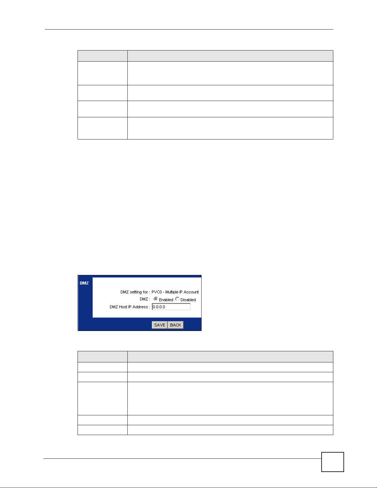
Table 21 Network > NAT > General (continued)
LABEL DESCRIPTION
Number of IPs Select Single if you have just one public WAN IP address for your ZyXEL Device.
Select Multiple if you have multiple public WAN IP addresses for your ZyXEL
Device.
DMZ Click this to configure the DMZ settings. See Section 10.3 on page 83 for more
details.
Virtual Server Click this to configure port forwarding rules for your ZyXEL Device. See Section
10.4 on page 84 for more details.
IP Address
Mapping
This is available only when you select Multiple in the Number of IPs field. Click
this to configure address mapping rules for your ZyXEL Device. See Section 10.5
on page 86 for more details.
10.3 The DMZ Screen
The DeMilitarized Zone (DMZ) provides a way for public servers (Web, e-mail, FTP, etc.) to
be visible to the outside world (while still being protected from DoS (Denial of Service)
attacks such as SYN flooding and Ping of Death). These public servers can also still be
accessed from the secure LAN.
Chapter 10 Network Address Translation (NAT)
By default the firewall allows traffic between the WAN and the DMZ, traffic from the DMZ to
the LAN is denied, and traffic from the LAN to the DMZ is allowed. Internet users can have
access to host servers on the DMZ but no access to the LAN, unless special filter rules
allowing access were configured by the administrator or the user is an authorized remote user.
Use this screen to configure a separate independent network from the LAN in which you can
put your servers. Click Advanced Setup > NAT > DMZ to open the following screen.
Figure 35 Advanced Setup > NAT > DMZ
The following table describes the labels in this screen.
Table 22 Advanced Setup > NAT > DMZ
LABEL DESCRIPTION
DMZ setting for This field displays the PVC you want to configure.
DMZ Use this field to enable or disable DMZ.
DMZ Host IP
Address
Type the IP address for DMZ in dotted decimal notation.
Note: Make sure the IP addresses of the LAN, WAN and DMZ are
on separate subnets.
SAVE Click this to save your settings.
BACK Click this to return to the previous screen without saving.
P-660R-T1 v3 User’s Guide
83
Page 84

Chapter 10 Network Address Translation (NAT)
10.4 The Virtual Server Screen
LAN computers usually have DHCP-assigned private IP address that cannot be accessed
directly from the WAN. Use this screen to allow the ZyXEL Device to forward traffic to the
servers on the LAN.
You may enter a single port number or a range of port numbers to be forwarded, and the local
IP address of the desired server. The port number identifies a service; for example, web
service is on port 80 and FTP on port 21. In some cases, such as for unknown services or
where one server can support more than one service (for example both FTP and web service),
it might be better to specify a range of port numbers. You can allocate a server IP address that
corresponds to a port or a range of ports.
The most often used port numbers and services are shown in Appendix D on page 205. Please
refer to RFC 1700 for further information about port numbers.
" Many residential broadband ISP accounts do not allow you to run any server
processes (such as a Web or FTP server) from your location. Your ISP may
periodically check for servers and may suspend your account if it discovers
any active services at your location. If you are unsure, refer to your ISP.
10.4.1 Configuring Servers Behind Port Forwarding (Example)
Let's say you want to assign ports 21-25 to one FTP, Telnet and SMTP server (A in the
example), port 80 to another (B in the example) and assign a default server IP address of
192.168.1.35 to a third (C in the example). You assign the LAN IP addresses and the ISP
assigns the WAN IP address. The NAT network appears as a single host on the Internet.
Figure 36 Multiple Servers Behind NAT Example
A=192.168.1.33
B=192.168.1.34
C=192.168.1.35
The following table summarizes the settings described in the above example.
Table 23 Multiple Servers Behind NAT Example
SERVERS PORTS DEFAULT SERVER IP
A FTP 21-22 192.168.1.33
B Telnet 23 192.168.1.34
C SMTP 25 192.168.1.35
LAN
192.168.1.1
IP Address assigned by ISP
WAN
84
P-660R-T1 v3 User’s Guide
Page 85

Chapter 10 Network Address Translation (NAT)
10.4.2 Configuring the Virtual Server Screen
Click Advanced Setup > NAT > Virtual Server to open the following screen.
See Appendix D on page 205 for port numbers commonly used for particular services.
Figure 37 Advanced Setup > NAT > Virtual Server
The following table describes the fields in this screen.
Table 24 Advanced Setup > NAT > Virtual Server
LABEL DESCRIPTION
Virtual Server
Virtual Server for This is the PVC that this virtual server will use.
Rule Index Select the rule’s index number from the drop-down list box.
Application Use the drop-down list box to select the type of server you have on your network.
Protocol Use the drop-down list box to choose the IP port (ALL, TCP or UDP) that defines
P-660R-T1 v3 User’s Guide
Applications or services are defined by their protocol (TCP or UDP) and port
number. For example, TCP port 80 defines web (HTTP) traffic. If you have a web
server on your network, you need to forward HTTP applications (TCP port 80) to
the server’s IP address.
Choices are: FTP, SSH, TELNET, SMTP, HTTP_Server, POP3, HTTPS, T. 12 0 ,
H.323, PPTP, pcAnywhere, VNC and CUSeeMe.
your service.
85
Page 86

Chapter 10 Network Address Translation (NAT)
Table 24 Advanced Setup > NAT > Virtual Server
LABEL DESCRIPTION
Start Port
Number
End Port Number Enter a port number in this field.
Local IP Address Enter the inside IP address of the server in this field.
Virtual Server Listing
Rule This is the rule’s index number.
Application This is a service’s name.
Protocol This is the IP port.
Start Port This is the first port number that identifies a service.
End Port This is the last port number that identifies a service.
Local IP Address This is the server’s IP address.
SAVE Click this to save your changes.
DELETE Click this to remove the rule.
BACK Click this to return to the previous screen without saving.
CANCEL Click this to restore your previously saved settings.
Enter a port number in this field.
To forward only one port, enter the port number again in the End Port Number
field.
To forward a series of ports, enter the start port number here and the end port
number in the End Port Number field.
To forward only one port, enter the port number again in the Start Port Number
field above and then enter it again in this field.
To forward a series of ports, enter the last port number in a series that begins with
the port number in the Start Port Number field above.
10.5 The IP Address Mapping Screen
Configure this screen if you have multiple IP addresses from your ISP and you want to map
them to private IP addresses on your LAN.
" The Address Mapping screen is available only when you select Multiple for
the Number of IPs in the NAT screen.
Ordering your rules is important because the ZyXEL Device applies the rules in the order that
you specify. When a rule matches the current packet, the ZyXEL Device takes the
corresponding action and the remaining rules are ignored.
86
P-660R-T1 v3 User’s Guide
Page 87

Chapter 10 Network Address Translation (NAT)
Use this screen to change your ZyXEL Device’s address mapping settings. Click Advanced
Setup > NAT > IP Address Mapping to open the following screen.
Figure 38 Advanced Setup > NAT > IP Address Mapping
The following table describes the fields in this screen.
Table 25 Network > NAT > Address Mapping
LABEL DESCRIPTION
IP Address Mapping
Address
Mapping Rule
Rule Index Select the rule’s index number from the drop-down list box.
Rule Type Choose the port mapping type from one of the following.
Local Start IP This is the starting local IP address. Local IP addresses are N/A for Server port
Local End IP This is the end local IP address. If your rule is for all local IP addresses, then enter
Public Start IP This is the starting public IP address. Enter 0.0.0.0 here if you have a dynamic IP
Public End IP This is the ending public IP address. This field is N/A for One-to-One, Many-to-One
The rules configured in this screen apply to this PVC.
One-to-One: This mode maps one local IP address to one public IP address. Note
that port numbers do not change for one-to-one NAT mapping type.
Many-to-One: This mode maps multiple local IP addresses to one public IP
address. This is equivalent to the Single IP feature that previous ZyXEL routers
supported only.
Many-to-Many Overload: This mode maps multiple local IP addresses to shared
public IP addresses.
Many-to-Many No Overload: This mode maps each local IP address to unique
public IP addresses.
Server: This type allows you to specify inside servers of different services behind
the NAT to be accessible to the outside world.
mapping.
0.0.0.0 as the Local Start IP address and 255.255.255.255 as the Local End IP
address.
This field is N/A for One-to-One and Server mapping types.
address from your ISP.
and Server mapping types.
P-660R-T1 v3 User’s Guide
87
Page 88

Chapter 10 Network Address Translation (NAT)
Table 25 Network > NAT > Address Mapping (continued)
LABEL DESCRIPTION
Address Mapping List
Rule This is the rule’s index number.
Type 1-1: One-to-One mode maps one local IP address to one public IP address. Note
that port numbers do not change for the One-to-One NAT mapping type.
M-1: Many-to-One mode maps multiple local IP addresses to one public IP address.
This is equivalent to the Single IP feature that previous ZyXEL routers supported
only.
M-M Ov (Overload): Many-to-Many Overload mode maps multiple local IP
addresses to shared public IP addresses.
MM No (No Overload): Many-to-Many No Overload mode maps each local IP
address to unique public IP addresses.
Server: This type allows you to specify inside servers of different services behind
the NAT to be accessible to the outside world.
Local Start IP This is the starting inside local IP address. Local IP addresses are N/A for Server
port mapping.
Local End IP This is the ending inside local IP address. If the rule is for all local IP addresses, then
Public Start IP This is the starting inside public IP address. Enter 0.0.0.0 here if you have a dynamic
Public End IP This is the ending inside public IP address. This field is N/A for One-to-one, Many-
SAVE Click this to save your changes.
DELETE Click this to remove the rule.
BACK Click this to return to the previous screen without saving.
CANCEL Click this to restore your previously saved settings.
this field displays 0.0.0.0 as the Local Start IP address and 255.255.255.255 as the
Local End IP address. This field is N/A for One-to-one and Server mapping types.
IP address from your ISP. You can only do this for Many-to-One and Server
mapping types.
to-One and Server mapping types.
10.6 NAT Technical Reference
This section contains more information regarding NAT.
10.6.1 NAT Definitions
Inside/outside denotes where a host is located relative to the ZyXEL Device, for example, the
computers of your subscribers are the inside hosts, while the web servers on the Internet are
the outside hosts.
Public/local denotes the IP address of a host in a packet as the packet traverses a router, for
example, the local address refers to the IP address of a host when the packet is in the local
network, while the public address refers to the IP address of the host when the same packet is
traveling in the WAN side.
88
P-660R-T1 v3 User’s Guide
Page 89

Note that inside/outside refers to the location of a host, while public/local refers to the IP
address of a host used in a packet. Thus, an inside local address is the IP address of an inside
host in a packet when the packet is still in the local network, while an inside public address is
the IP address of the same inside host when the packet is on the WAN side. The following
table summarizes this information.
Table 26 NAT Definitions
ITEM DESCRIPTION
Inside This refers to the host on the LAN.
Outside This refers to the host on the WAN.
Local This refers to the packet address (source or destination) as the packet travels on the
LAN.
Public This refers to the packet address (source or destination) as the packet travels on the
WAN.
NAT never changes the IP address (either local or public) of an outside host.
10.6.2 What NAT Does
In the simplest form, NAT changes the source IP address in a packet received from a
subscriber (the inside local address) to another (the inside public address) before forwarding
the packet to the WAN side. When the response comes back, NAT translates the destination
address (the inside public address) back to the inside local address before forwarding it to the
original inside host. Note that the IP address (either local or public) of an outside host is never
changed.
Chapter 10 Network Address Translation (NAT)
The public IP addresses for the inside hosts can be either static or dynamically assigned by the
ISP. In addition, you can designate servers, for example, a web server and a telnet server, on
your local network and make them accessible to the outside world. If you do not define any
servers, NAT offers the additional benefit of firewall protection. With no servers defined, your
ZyXEL Device filters out all incoming inquiries, thus preventing intruders from probing your
network.
10.6.3 How NAT Works
Each packet has two addresses – a source address and a destination address. For outgoing
packets, the inside local address is the source address on the LAN, and the inside public
address is the source address on the WAN. For incoming packets, the inside local address is
the destination address on the LAN, and the inside public address is the destination address on
the WAN. NAT maps private (local) IP addresses to globally unique ones required for
communication with hosts on other networks. It replaces the original IP source address (and
TCP or UDP source port numbers for Many-to-One and Many-to-Many Overload NAT
mapping) in each packet and then forwards it to the Internet. The ZyXEL Device keeps track
of the original addresses and port numbers so incoming reply packets can have their original
values restored. The following figure illustrates this.
P-660R-T1 v3 User’s Guide
89
Page 90

Chapter 10 Network Address Translation (NAT)
Figure 39 How NAT Works
LAN
192.168.1.13
NAT Table
Inside Local
IP Address
192.168.1.10
192.168.1.11
192.168.1.12
192.168.1.13
Inside Public
IP Address
1
2
3
4
WAN
192.168.1.12
192.168.1.11
192.168.1.10
SA
192.168.1.10
Inside Local
Address
SA
1
Inside Public
Address
90
P-660R-T1 v3 User’s Guide
Page 91

CHAPTER 11
Quality of Service (QoS)
11.1 Overview
Use the QoS screen to set up your ZyXEL Device to use QoS for traffic management.
Quality of Service (QoS) refers to both a network’s ability to deliver data with minimum
delay, and the networking methods used to control bandwidth. QoS allows the ZyXEL Device
to group and prioritize application traffic and fine-tune network performance.
Without QoS, all traffic data are equally likely to be dropped when the network is congested.
This can cause a reduction in network performance and make the network inadequate for timecritical applications such as video-on-demand.
The ZyXEL Device assigns each packet a priority and then queues the packet accordingly.
Packets assigned with a high priority are processed more quickly than those with low priorities
if there is congestion, allowing time-sensitive applications to flow more smoothly. Timesensitive applications include both those that require a low level of latency (delay) and a low
level of jitter (variations in delay) such as Voice over IP (VoIP) or Internet gaming, and those
for which jitter alone is a problem such as Internet radio or streaming video.
In the following figure, your Internet connection has an upstream transmission speed of 50
Mbps. You configure a classifier to assign the highest priority queue (6) to VoIP traffic from
the LAN interface, so that voice traffic would not get delayed when there is network
congestion. Traffic from the boss’s IP address (192.168.1.23 for example) is mapped to queue
5. Traffic that does not match these two classes are assigned priority queue based on the
internal QoS mapping table on the ZyXEL Device.
Figure 40 QoS Example
VoIP: Queue 6
DSL
50 Mbps
Boss: Queue 5
IP=192.168.1.23
P-660R-T1 v3 User’s Guide
91
Page 92

Chapter 11 Quality of Service (QoS)
11.1.1 What You Can Do in the QoS Screens
• Use the QoS screen (Section 11.2 on page 93) to configure QoS settings on the ZyXEL
Device.
• Use the QoS Settings Summary screen (Section 11.2.1 on page 95) to check the summary
of QoS rules and actions you configured for the ZyXEL Device.
11.1.2 What You Need to Know About QoS
802.1p
QoS is used to prioritize source-to-destination traffic flows. All packets in the same flow are
given the same priority. 802.1p is a way of managing traffic in a network by grouping similar
types of traffic together and treating each type as a class. You can use 802.1p to give different
priorities to different packet types.
Tagging and Marking
In a QoS class, you can configure whether to add or change the DiffServ Code Point (DSCP)
value, IEEE 802.1p priority level and VLAN ID number in a matched packet. When the packet
passes through a compatible network, the networking device, such as a backbone switch, can
provide specific treatment or service based on the tag or marker.
Finding Out More
See Section 11.3 on page 96 for advanced technical information on QoS.
92
P-660R-T1 v3 User’s Guide
Page 93

11.2 The QoS Screen
Use this screen to enable or disable QoS and have the ZyXEL Device assign priority levels to
traffic according to the port range, IEEE 802.1p priority level and/or IP precedence.
Click Advanced Setup > QoS to open the screen as shown next.
Figure 41 Advanced Setup > QoS
Chapter 11 Quality of Service (QoS)
The following table describes the labels in this screen.
Table 27 Advanced Setup > QoS
LABEL DESCRIPTION
Quality of Service
QoS Use this field to turn on QoS to improve your network performance.
Summary Click this to open a summary table showing the QoS settings. See Section 11.2.1
Rule
P-660R-T1 v3 User’s Guide
You can give priority to traffic that the ZyXEL Device forwards out through the WAN
interface. Give high priority to voice and video to make them run more smoothly.
Similarly, give low priority to many large file downloads so that they do not reduce
the quality of other applications.
on page 95 for more details.
93
Page 94

Chapter 11 Quality of Service (QoS)
Table 27 Advanced Setup > QoS
LABEL DESCRIPTION
Rule Index Select the rule’s index number from the drop-down list box.
Active Use this field to enable or disable the rule.
Application Select an application from the drop-down list box. The Destination Port Range and
Protocol ID fields may change depending on the type of applications you choose.
Physical Ports Select Enet1 to apply the rule to the Ethernet port.
Destination MAC Type a destination MAC address here. QoS is then applied to traffic containing this
IP Enter a destination IP address in dotted decimal notation. QoS is then applied to
Mask Enter a destination subnet mask here.
Port Range Either use the default value set by the application you choose, or enter the port
Source MAC Type a source MAC address here. QoS is then applied to traffic containing this
IP Enter a source IP address in dotted decimal notation. QoS is then applied to traffic
Mask Enter a source subnet mask here.
Port Range Enter the port number to which the rule should be applied. 0 means any source port
Protocol ID Select an IP protocol type from the drop-down list box.
Vlan ID Range Enter the source VLAN ID in this field.
IPP/DS Field Select IPP/TOS to specify an IP precedence range and type of services.
IP Precedence
Range
Type of Service Select a type of service from the drop-down list box.
DSCP Range Specify a DSCP number between 0 and 63 in this field.
802.1p Select a priority level (0 to 7) from the drop-down list box.
Action
IPP/DS Field Select IPP/TOS to specify an IP precedence range and type of services.
IP Precedence
Remarking
Type of Service
Remarking
DSCP
Remarking
802.1p
Remarking
destination MAC address. Leave it blank to apply the rule to all MAC addresses.
traffic containing this destination IP address. A blank destination IP address means
any destination IP address.
number to which the rule should be applied.
source MAC address. Leave it blank to apply the rule to all MAC addresses.
containing this source IP address. A blank source IP address means any source IP
address.
number. See Appendix D on page 205 for some common services and port
numbers.
Select DSCP to specify a DiffServ Code Point (DSCP) range.
Enter a range from 0 to 7 for IP precedence. Zero is the lowest priority and seven is
the highest.
Available options are: Normal service, Minimize delay, Maximize throughput,
Maximize reliability and Minimize monetary cost.
Select DSCP to specify a DiffServ Code Point (DSCP) range.
Enter a range from 0 to 7 to re-assign IP precedence to matched traffic. Zero is the
lowest priority and seven is the highest.
Select a type of service to re-assign the priority level to matched traffic.
Available options are: Normal service, Minimize delay, Maximize throughput,
Maximize reliability and Minimize monetary cost.
Specify a DSCP number between 0 and 63 to re-assign the priority level to matched
traffic.
Select a priority level (0 to 7) to re-assign the priority level to matched traffic.
94
P-660R-T1 v3 User’s Guide
Page 95

Table 27 Advanced Setup > QoS
LABEL DESCRIPTION
Queue # Specify a Low, Medium, High or Highest queue tag to matched traffic. Traffic
assigned to a higher queue gets through faster while traffic in lower queues is
dropped when there is network congestion.
ADD Click this to add the rule.
DELETE Click this to remove the rule.
CANCEL Click this to restore previously saved settings.
11.2.1 The QoS Settings Summary Screen
Use this screen to display a summary of rules and actions configured for the ZyXEL Device.
In the Advanced > QoS screen, click the QoS Settings Summary button to open the
following screen.
Figure 42 Advanced Setup > QoS > QoS Settings Summary
Chapter 11 Quality of Service (QoS)
The following table describes the labels in this screen.
Table 28 Advanced Setup > QoS > QoS Settings Summary
LABEL DESCRIPTION
Rules
# This is the rule’s index number.
Active This shows whether the rule is enabled or disabled.
Physical Ports This is the physical port associated with the rule.
Destination MAC
and IP/Mask Port
Ranges
Source MAC and
IP/Mask Port
Ranges
Protocol ID This is the protocol ID associated with the rule.
VLAN ID This is the VLAN ID associated with the rule.
IPP/TOS (DSCP) This shows the IPP/TOS or DSCP settings.
802.1p This is the 802.1p priority level.
Actions
This is the port range for destination MAC address and IP address.
This is the port range for source MAC address and IP address.
P-660R-T1 v3 User’s Guide
95
Page 96

Chapter 11 Quality of Service (QoS)
Table 28 Advanced Setup > QoS > QoS Settings Summary (continued)
LABEL DESCRIPTION
IPP/TOS (DSCP)
Remarking
802.1p Remarking The ZyXEL Device re-assigns the priority levels specified in this field to
Queue # The ZyXEL Device assigns the queue level specified in this field to matched
The ZyXEL Device re-assigns the priority values specified in this field to
matched traffic.
matched traffic.
traffic.
11.3 QoS Technical Reference
This section provides some technical background information about the topics covered in this
chapter.
11.3.1 IEEE 802.1p
IEEE 802.1p specifies the user priority field and defines up to eight separate traffic types. The
following table describes the traffic types defined in the IEEE 802.1d standard (which
incorporates the 802.1p).
Table 29 IEEE 802.1p Priority Level and Traffic Type
PRIORITY
LEVEL
Level 7 Typically used for network control traffic such as router configuration messages.
Level 6 Typically used for voice traffic that is especially sensitive to jitter (jitter is the variations in
Level 5 Typically used for video that consumes high bandwidth and is sensitive to jitter.
Level 4 Typically used for controlled load, latency-sensitive traffic such as SNA (Systems
Level 3 Typically used for “excellent effort” or better than best effort and would include important
Level 2 This is for “spare bandwidth”.
Level 1 This is typically used for non-critical “background” traffic such as bulk transfers that are
Level 0 Typically used for best-effort traffic.
TRAFFIC TYPE
delay).
Network Architecture) transactions.
business traffic that can tolerate some delay.
allowed but that should not affect other applications and users.
11.3.2 IP Precedence
Similar to IEEE 802.1p prioritization at layer-2, you can use IP precedence to prioritize
packets in a layer-3 network. IP precedence uses three bits of the eight-bit ToS (Type of
Service) field in the IP header. There are eight classes of services (ranging from zero to seven)
in IP precedence. Zero is the lowest priority level and seven is the highest.
96
P-660R-T1 v3 User’s Guide
Page 97

11.3.3 Automatic Priority Queue Assignment
If you enable QoS on the ZyXEL Device, the ZyXEL Device can automatically base on the
IEEE 802.1p priority level, IP precedence and/or packet length to assign priority to traffic
which does not match a class.
The following table shows you the internal layer-2 and layer-3 QoS mapping on the ZyXEL
Device. On the ZyXEL Device, traffic assigned to higher priority queues gets through faster
while traffic in lower index queues is dropped if the network is congested.
Table 30 Internal Layer2 and Layer3 QoS Mapping
LAYER 2 LAYER 3
Chapter 11 Quality of Service (QoS)
PRIORITY
QUEUE
0 1 0 000000
12
2 0 0 000000 >1100
3 3 1 00 1110
44 2 010110
5 5 3 01111 0
66 4 100110
7 7 6 110000
IEEE 802.1P USER
PRIORITY
(ETHERNET
PRIORITY)
TOS (IP
PRECEDENCE)
5 101110
7
DSCP
001100
001010
001000
010100
010010
010000
011100
011010
011000
100100
100010
100000
101000
111000
IP PACKET
LENGTH (BYTE)
250~1100
<250
P-660R-T1 v3 User’s Guide
97
Page 98

Chapter 11 Quality of Service (QoS)
98
P-660R-T1 v3 User’s Guide
Page 99

CHAPTER 12
ADSL
12.1 Overview
This chapter contains information about configuring the ADSL settings for your ZyXEL
Device.
12.2 The ADSL Screen
Use this screen to select the ADSL mode and type for your ZyXEL Device. Click Advanced
Setup > ADSL to open the following screen.
Figure 43 Advanced Setup > ADSL
The following table describes the labels in this screen.
Table 31 Advanced Setup > ADSL
LABEL DESCRIPTION
ADSL Mode Select the mode supported by your ISP.
ADSL Type Select the type supported by your ISP.
SAVE Click this to save your changes.
P-660R-T1 v3 User’s Guide
Use Auto Sync-Up if you are not sure which mode to choose from. The ZyXEL
Device dynamically diagnoses the mode supported by the ISP and selects the
best compatible one for your connection.
Other options are ADSL2+, ADSL2, G. DMT, T1.413 and G.lite.
Available options are ANNEX A, ANNEX A/L, ANNEX M and ANNEX A/L/M.
99
Page 100

Chapter 12 ADSL
100
P-660R-T1 v3 User’s Guide
 Loading...