


P-660N-T1A
802.11n Wireless ADSL2+ Gateway
Default Login Details
IP Address http://192.168.1.1
Password 1234
Firmware Version 3.40
Edition 1, 7/2010
www.zyxel.com
www.zyxel.com
Copyright © 2010
ZyXEL Communications Corporation


About This User's Guide
About This User's Guide
Intended Audience
This manual is intended for people who want to configure the Zy XEL Device using
the web configurator. You should have at least a basic knowledge of TCP/IP
networking concepts and topology.
Related Documentation
•Quick Start Guide
The Quick Start Guide is designed to help you get up and running right away. It
contains information on setting up your network and configuring for Internet
access.
• Support Disc
Refer to the included CD for support documents.
• ZyXEL Web Site
Please refer to www.zyxel.com
product certifications.
for additional support documentation and
Documentation Feedback
Send your comments, questions or suggestions to: techwriters@zyxel.com.tw
Thank you!
The Technical Writing Team, ZyXEL Communications Corp.,
6 Innovation Road II, Science-Based Industrial Park, Hsinchu, 30099, Taiwan.
Need More Help?
More help is available at www.zyx el.com.
P-660N-T1A User’s Guide
3

About This User's Guide
• Download Library
Search for the latest product updates and documentation from this link. Read
the Tech Doc Overview to find out how to efficiently use the User Guide, Quick
Start Guide and Command Line Interface Reference Guide in order to better
understand how to use your product.
• Knowledge Base
If you have a specific question about your product, the answer may be here.
This is a collection of answers to previously asked questions about ZyXEL
products.
•Forum
This contains discussions on ZyXEL prod ucts. Learn from others who use ZyXEL
products and share your experiences as well.
Customer Support
In the event of problems that cannot be solved by using this manual, you should
contact your vendor. If you cannot contact your vendor, then contact a ZyXEL
office for the region in which you bought the device. See ht t p ://www.zyxel.com/
web/contact_us.php for contact information. Please have the following information
ready when you contact an office.
• Product model and serial number.
•Warranty Information.
• Date that you received your device.
• Brief description of the problem and the steps you took to solve it.
Disclaimer
Graphics in this book may differ slightly from the product due to differences in
operating systems, operating system versions, or if you installed updated
firmware/software fo r y our dev ice. Ev ery effort has been made to ensur e that the
information in this manual is accurate.
4
P-660N-T1A User’s Guide

Document Conventions
Document Conventions
Warnings and Notes
These are how warnings and notes are shown in this User’s Guide.
Warnings tell you about things that could harm you or your device.
Note: Notes tell you other important information (for example, other things you may
need to configure or helpful tips) or recommendations.
Syntax Conventions
• The P-660N-T1A may be referred to as the “ZyXEL Device”, the “device”, the
“system” or the “product” in this User’s Guide.
• Product labels, screen names, field labels and field choices are all in bold font.
• A key stroke is denoted by square brackets and uppercase text, for example,
[ENTER] means the “enter” or “ret urn” key on your keyboard.
• “Enter” means for you to type one or more characters and then press the
[ENTER] key. “Select” or “choose” means for you to use one of the predefined
choices.
• A right angle bracket ( > ) within a screen name denotes a mouse click. For
example, Maintenance > Log > Log Setting means you first click
Maintenance in the navigation panel, then the Log sub menu and finally the
Log Setting tab to get to that screen.
• Units of measurement may denote the “metric” value or the “scientific” value.
For example, “k” for kilo may denote “1000” or “1024”, “M” for mega may
denote “1000000” or “1048576” and so on.
• “e.g.,” is a shorthand for “for instance”, and “i.e.,” means “that is” or “in other
words”.
P-660N-T1A User’s Guide
5
Document Conventions
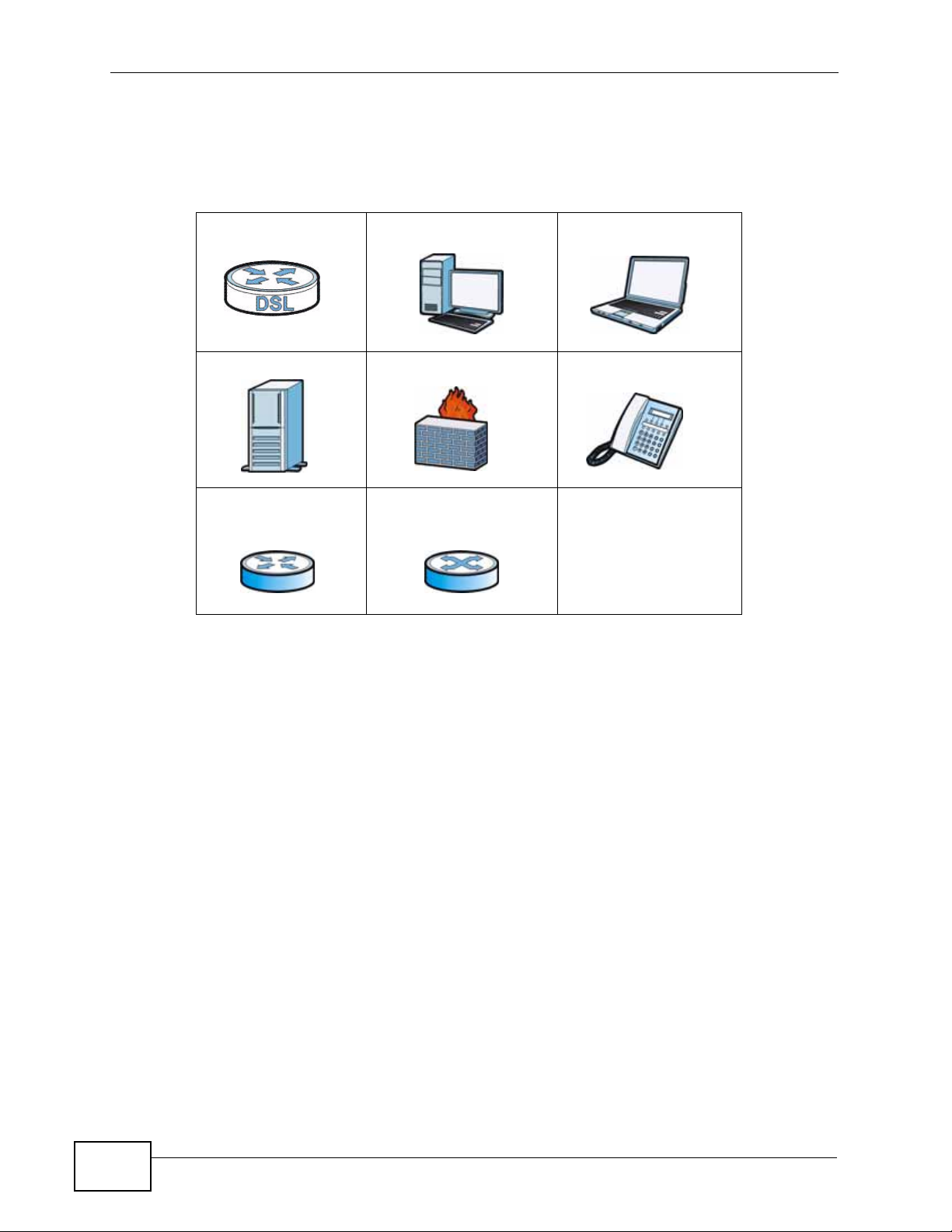
Icons Used in Figures
Figures in this User’s Guide may use the following generic icons. The Z yXEL Device
icon is not an exact representation of your device.
ZyXEL Device Computer Notebook computer
Server Firewall Telephone
Router Switch
6
P-660N-T1A User’s Guide

Safety Warnings
Safety Warnings
• Do NOT use this product near water, for example, in a wet basement or near a swimming
pool.
• Do NOT expose your device to dampness, dust or corrosive liquids.
• Do NOT store things on the device.
• Do NOT install, use, or service this device during a thunderstorm. There is a remote risk
of electric shock from lightning.
• Connect ONLY suitable accessories to the device.
• Do NOT open the device or unit. Opening or removing covers can expose you to
dangerous high voltage points or other risks. ONLY qualified service personnel should
service or disassemble this device. Please contact your vendor for further information.
• Make sure to connect the cables to the correct ports.
• Place connecting cables carefully so that no one will step on them or stumble over them.
• Always disconnect all cables from this device before servicing or disassembling.
• Use ONLY an appropriate power adaptor or cord for your device.
• Connect the power adaptor or cord to the right supply voltage (for example, 110V AC in
North America or 230V AC in Europe).
• Do NOT allow anything to rest on the power adaptor or cord and do NOT place the
product where anyone can walk on the power adaptor or cord.
• Do NOT use the device if the power adaptor or cord is damaged as it might cause
electrocution.
• If the power adaptor or cord is damaged, remove it from the device and the power
source.
• Do NOT attempt to repair the power adaptor or cord. Contact your local vendor to order a
new one.
• Do not use the device outside, and make sure all the connections are indoors. There is a
remote risk of electric shock from lightning.
• Do NOT obstruct the device ventilation slots, as insufficient airflow may harm your
device.
• Use only No. 26 AWG (American Wire Gauge) or larger telecommunication line cord.
• Antenna Warning! This device meets ETSI and FCC certification requirements when using
the included antenna(s). Only use the included antenna(s).
Your product is marked with this symbol, which is known as the WEEE mark. WEEE
stands for Waste Electronics and Electrical Equipment. It means that used electrical
and electronic products should not be mixed with general waste. Used electrical and
electronic equipment should be treated separately.
P-660N-T1A User’s Guide
7

Safety Warnings
8
P-660N-T1A User’s Guide

Contents Overview
Contents Overview
User’s Guide ........................................................................................................ ...................19
Introduction .................................. .................................................... .......................................... 21
The Web Configurator ...............................................................................................................27
Status Screen ............................................................................................................................ 35
Tutorials ..................................................................................................................................... 39
Technical Reference ..............................................................................................................51
Internet and Wireless Setup Wizard....................... ... .... ... ... ... .... ... ............................................ 53
WAN Setup ............................ ............................................. ... .... ... ... ... ... .... ................................ 67
LAN Setup ................................................................................................................................. 85
Wireless LAN ............................ ... .... ... ... ............................................. ... .... ... ... ... .... ................... 99
Network Address Translation (NAT) ........................................................................................ 133
Firewall .................................................................................................................................... 149
Filters ..................................... .................................................... .............................................. 153
Static Route ............................................................................................................................. 159
802.1Q/1P ............................................................................................................................... 163
Quality of Service (QoS) ............................................................................ ... ... ... ..................... 169
Dynamic DNS Setup ................................................................................................................ 177
Remote Management ..............................................................................................................179
Universal Plug-and-Play (UPnP) ............................................................................................. 189
CWMP ..................................................................................................................................... 199
System Settings ........... ............................................. .... ... ... ... .... ... ........................................... 203
Logs ....................................... .................................................... .............................................. 207
Tools ........................................................................................................................................ 217
Diagnostic .................................... ....................................................... ..................................... 225
Troubleshooting ..................................................... .................................................................. 229
Product Specifications ............................................................................................................. 235
P-660N-T1A User’s Guide
9

Contents Overview
10
P-660N-T1A User’s Guide

Table of Contents
Table of Contents
About This User's Guide..........................................................................................................3
Document Conventions............................................................................................................5
Safety Warnings ........................................................................................................................7
Contents Overview ...................................................................................................................9
Table of Contents....................................................................................................................11
Part I: User’s Guide................................................................................ 19
Chapter 1
Introduction.............................................................................................................................21
1.1 Overview ............. ............................................. ... .... ... ... ... .... ................................................ 21
1.2 Ways to Manage the ZyXEL Device ................... .... ... ... ... .... ... ............................................. 21
1.2.1 Good Habits for Managing the ZyXEL Device ........................................................... 22
1.3 Internet Access ...................... .... ... ... ... ... .... ............................................. ... ... .... ... ... ... .......... 22
1.4 Wireless Access ....... .... .......................................................................................................23
1.4.1 Using the WPS/WLAN Button ... ... .... ... ... ................................................. ... ... ............. 24
1.5 LEDs (Lights) ......................... .... ... ... ............................................. ... .... ... ... ... .... ... ................ 25
1.6 The RESET Button ................................ .... ... ... ... .............................................. ... ... ... ... ....... 26
1.6.1 Using the Reset Button ................ .... ... ... ... .... ............................................................. 26
Chapter 2
The Web Configurator............................................................................................................27
2.1 Overview ............. ............................................. ... .... ... ... ... .... ................................................ 27
2.1.1 Accessing the Web Configurator ................................................................................ 27
2.2 Main Screen ................................................. ... ... .... ... ... ... .... ................................................ 30
2.2.1 Title Bar .................................. ... ............................................. .... ... ... .......................... 31
2.2.2 Navigation Panel .......... .... ... ... ... ................................................................................. 31
2.2.3 Main Window .......................... ... ............................................. .... ... ... ... .... ... ... .............33
2.2.4 Status Bar ............................................... ... .............................................. ... ................ 34
Chapter 3
Status Screen..........................................................................................................................35
3.1 Overview ............. ............................................. ... .... ... ... ... .... ................................................ 35
3.2 The Status Screen ............................................................................................................... 35
P-660N-T1A User’s Guide
11

Table of Contents
Chapter 4
Tutorials...................................................................................................................................39
4.1 Overview ............. ............................................. ... .... ... ... ... .... ................................................ 39
4.2 Setting Up a Secure Wireless Network ............................... ... ... ... ... .... ................................ 39
4.2.1 Configuring the Wireless Network Settings ............................................................. ... 39
4.2.2 Using WPS ................................... .... ... ... ... .... ... ... ............................................. ... .... ... 41
4.2.3 Without WPS .................................... ... ... ... .... ... ... ... ............................................. .... ...45
4.2.4 Setting Up Wireless Network Scheduling ............... .... ... ... ... ... .... ... ... ... .... ................... 45
4.3 Configuring the MAC Address Filter .................................................................................... 46
4.4 Multiple WAN Connections Example ................................................... ................................ 48
Part II: Technical Reference.................................................................. 51
Chapter 5
Internet and Wireless Setup Wizard......................................................................................53
5.1 Overview ............. ............................................. ... .... ... ... ... .... ................................................ 53
5.2 Internet Access Wizard Setup ............................................................................................. 53
5.2.1 Manual Configuration ....... ... ... ... ... .... ... ... ... .... ... ................................................ ... .... ... 56
5.3 Wireless Connection Wizard Setup ..................................................................................... 62
5.3.1 Manually Assign a WPA-PSK key ................................. ............................................. 64
5.3.2 Manually Assign a WEP Key ...................................................................................... 65
Chapter 6
WAN Setup...............................................................................................................................67
6.1 Overview ............. ............................................. ... .... ... ... ... .... ................................................ 67
6.1.1 What Yo u Can Do in the WAN Screens ..................................................................... 67
6.1.2 What You Need to Know ........ ... ... .... ... ... .................................................................... 67
6.1.3 Before You Begin ............................................. ... ... .... ... ... ... ... .... ... ... .......................... 68
6.2 The Internet Connection Screen .......................................................................................... 69
6.2.1 Advanced Setup .................................. ............................................. ... .... ... ... ... .......... 72
6.3 The More Connections Screen .................................. ... ... .... ... ............................................. 74
6.3.1 More Connections Edit .............................. .... ... ... ... .... ... ... .......................................... 75
6.3.2 Advanced Setup .................................. ............................................. ... .... ... ... ... ... .... ... 77
6.4 Technical Reference ........................ ... ... .... ... ... ... ................................................................. 78
6.4.1 Encapsulation ................... ... ... ... ... .............................................. ... ... ... .... ... ... .............78
6.4.2 Multiplexing ............ ... ... .... ... ... ... ... .... ............................................. ... ... .... ... ... ... ..........80
6.4.3 VPI and VCI ........................................................ ... .... ... ... .......................................... 80
6.4.4 IP Address Assignment .......................................... .... ... ... .......................................... 80
6.4.5 Nailed-Up Connection (PPP) ..................................................................................... 81
6.4.6 NAT .............................................. .... ... ............................................. ... ....................... 81
6.5 Traffic Shaping ....................................... .... ... ... ... .... ... ... ... .................................................... 81
12
P-660N-T1A User’s Guide

Table of Contents
6.5.1 ATM Traffic Classes ...................................................................................................82
Chapter 7
LAN Setup................................................................................................................................85
7.1 Overview ............. ............................................. ... .... ... ... ... .... ................................................ 85
7.1.1 What Yo u Can Do in the LAN Screens ....................................................................... 85
7.1.2 What You Need To Know .................................... ... .... ... ............................................. 86
7.1.3 Before You Begin ............................................. ... ... .... ... ... ... ... .... ... ... .......................... 87
7.2 The IP Screen .................. ... ... .... ............................................. ... ... ... .... ... ... ... .... ... ... .............87
7.2.1 The Advanced Setup Screen ..................................................................................... 88
7.3 The DHCP Server Screen ................................................................................................... 89
7.4 The Client List Screen ......................................................................................................... 90
7.5 The IP Alias Screen ................................... ................................................ ... .... ................... 91
7.5.1 Configuring the LAN IP Alias Screen ......................................................................... 92
7.6 Technical Reference ........................ ... ... .... ... ... ... ................................................................. 94
7.6.1 LANs, WANs and the ZyXEL Device .......................................................................... 94
7.6.2 DHCP Setup ..................... ... ... ... ... .... ... ... ... .............................................. ... ... ... ... .... ...94
7.6.3 DNS Server Addresses .......................................... .... ... ............................................. 94
7.6.4 LAN TCP/IP .................. .... ... ... ............................................. ... .... ... ............................. 95
7.6.5 RIP Setup ............................................................................... .... ... ... ... .... ... ... .............96
7.6.6 Multicast . ... ... ... .............................................. ... ... ... ............................................. ....... 97
Chapter 8
Wireless LAN...........................................................................................................................99
8.1 Overview ............. ............................................. ... .... ... ... ... .... ................................................ 99
8.1.1 What You Can Do in the Wireless LAN Screens ........................................................ 99
8.1.2 What You Need to Know ........ ... ... .... ... ... .................................................................. 100
8.1.3 Before You Start ..................................... ... .............................................. ... ... ... ... .... . 101
8.2 The AP Screen ............. ... ... ............................................................................................... 101
8.2.1 No Security .......................... ... ............................................. ... .... ... ... ... .... .................103
8.2.2 WEP Encryption ..... ... ... .... ............................................. ... ... ... .... ... ... ... ..................... 103
8.2.3 WPA(2)-PSK ............................................................................................................ 105
8.2.4 WPA(2) Authentication .............................. .... ... ... ... .... ... ... ... ... .................................. 106
8.2.5 Advanced Setup .................................. ............................................. ... .... ... ... ... ... .... . 107
8.2.6 MAC Filter ............................................................................................................ 109
8.3 The More AP Screen .......................................... .... ... ... ... .... ... ... ... ... .... ...............................110
8.3.1 More AP Edit .............................................................................................................111
8.4 The WPS Screen ................................... .... ................................................ ... .... ..................112
8.5 The WPS Station Screen ................. ... ... .... ................................................ ... .... ... ... ... ... .... ..113
8.6 The WDS Screen ................................................................................................................114
8.7 The Scheduling Screen ......................................................................................................116
8.8 Technical Reference ........................ ... ... .... ... ... ... ................................................................117
8.8.1 Wireless Network Overview ...... ... .... ... ... ... .... ... ... ... ...................................................117
P-660N-T1A User’s Guide
13

Table of Contents
8.8.2 Additional Wireless Terms .........................................................................................119
8.8.3 Wireless Security Overview ......................................................................................119
8.8.4 Signal Problems ........ ... .... ... ... ... ... .... ........................................................................ 122
8.8.5 BSS ..........................................................................................................................122
8.8.6 MBSSID .............................................. ... ... .............................................. ... ... ... ........123
8.8.7 Wireless Distribution System (WDS) ........................................................................ 124
8.8.8 WiFi Protected Setup (WPS) .................................................................................... 124
Chapter 9
Network Address Translation (NAT)....................................................................................133
9.1 Overview ............. ............................................. ... .... ... ... ... .... .............................................. 133
9.1.1 What You Can Do in the NAT Screens ..................................................................... 133
9.1.2 What You Need To Know .................................... ... .... ... ........................................... 133
9.2 The General Setup Screen ................................................................................................ 135
9.3 The Port Forwarding Screen ............................................................................................. 136
9.3.1 Configuring the Port Forwarding Screen ............................. ..................................... 137
9.3.2 The Port Forwarding Rule Edit Screen .................................................................... 139
9.4 The Address Mapping Screen ........................................................................................... 140
9.4.1 The Address Mapping Rule Edit Screen .................................................................. 142
9.5 The ALG Screen .............................. ... ... .... ... ... ... .... ... ... ... .................................................. 143
9.6 Technical Reference ........................ ... ... .... ... ... ... ............................................................... 144
9.6.1 NAT Definitions ............ .... ... ... ... ... .... ... ............................................. ... .... ... ... ... ... .....144
9.6.2 What NAT Does ............... ... ... ... ... .... ... ............................................. ... .... ... ... ... ... .... . 144
9.6.3 How NAT Works ....................................................................................................... 145
9.6.4 NAT Application ...................................................... .... ... ... ... ..................................... 146
9.6.5 NAT Mapping Types ..................... .... ... ... ... .... ... ... ... ............................................. .... . 146
Chapter 10
Firewall...................................................................................................................................149
10.1 Overview .......................................................................................................................... 149
10.1.1 What You Can Do in the Firewall Screens ............................................................. 149
10.1.2 What You Need to Know ........................................................................................ 149
10.2 The Firewall Screen ................. ... ... ... ... ................................................. ... ... .... ................. 151
Chapter 11
Filters.....................................................................................................................................153
11.1 Overview .........................................................................................................................153
11.1.1 What You Can Do in the Filter Screens ................................................. ................. 153
11.1.2 What You Need to Know ........................................................................................ 153
11.2 The URL Filter Screen ....................................................................................................154
11.3 The Application Filter Screen ........................................................................................... 155
11.4 The IP/MAC Filter Screen ................................................................................................ 156
14
P-660N-T1A User’s Guide

Table of Contents
Chapter 12
Static Route...........................................................................................................................159
12.1 Overview ......................................................................................................................... 159
12.1.1 What You Can Do in the Static Route Screens ...................................................... 160
12.2 The Static Route Screen .................................................................................................. 160
12.2.1 Static Route Edit ................................................................................................... 161
Chapter 13
802.1Q/1P...............................................................................................................................163
13.1 Overview .......................................................................................................................... 163
13.1.1 What You Can Do in the 802.1Q/1P Screens ........................................................ 163
13.1.2 What You Need to Know ........................................................................................ 163
13.2 The 802.1Q/1P Group Setting Screen .............................................................................165
13.2.1 Editing 802.1Q/1P Group Setting ................................... ... ... .... .............................. 166
13.3 The 802.1Q/1P Port Setting Screen ................................................................................168
Chapter 14
Quality of Service (QoS).......................................................................................................169
14.1 Overview .......................................................................................................................... 169
14.1.1 What You Can Do in the QoS Screens .................................................................. 170
14.1.2 What You Need to Know ........................................................................................ 170
14.2 The QoS Screen .............................................................................................................171
14.2.1 The QoS Settings Summary Screen ...................................................................... 173
14.3 Technical Reference ........................................................................................................ 174
14.3.1 IEEE 802.1p ...........................................................................................................174
14.3.2 IP Precedence ........................................................................................................ 175
14.3.3 Automatic Priority Queue Assignment ................................................................... 175
Chapter 15
Dynamic DNS Setup .............................................................................................................177
15.1 Overview .......................................................................................................................... 177
15.1.1 What You Can Do in the DDNS Screen ................................................................. 177
15.1.2 What You Need To Know ....................................................................................... 177
15.2 The Dynamic DNS Screen ................................................ ... ... ... ... .... ... ... ... .... ... ... ........... 178
Chapter 16
Remote Management............................................................................................................179
16.1 Overview .......................................................................................................................... 179
16.1.1 What You Can Do in the Remote Management Screens ....................................... 180
16.1.2 What You Need to Know ........................................................................................ 180
16.2 The WWW Screen ........................................................................................................... 181
16.2.1 Configuring the WWW Screen ............................................................................... 181
16.3 The Telnet Screen ........................................................................................................... 182
P-660N-T1A User’s Guide
15

Table of Contents
16.4 The FTP Screen ............... ... .... ... ................................................ ... .... ... ........................... 183
16.5 The SNMP Screen ...........................................................................................................184
16.5.1 Supported MIBs ..................................................................................................... 185
16.5.2 SNMP Traps ........................................................................................................... 185
16.5.3 Configuring SNMP .................................................................................................186
16.6 The DNS Screen .................................................... ... ... .... ... ... ... ... .................................. 186
16.7 The ICMP Screen ............................................................................................................ 187
Chapter 17
Universal Plug-and-Play (UPnP)..........................................................................................189
17.1 Overview .......................................................................................................................... 189
17.1.1 What You Can Do in the UPnP Screen .................................................................. 189
17.1.2 What You Need to Know ........................................................................................ 189
17.2 The UPnP Screen ............................................................................................................191
17.2.1 Installing UPnP in Windows ................................................................................... 192
17.2.2 Using UPnP in Windows XP .......................................................... ... .... ... ... ... ... .... . 194
Chapter 18
CWMP.....................................................................................................................................199
18.1 Overview .......................................................................................................................... 199
18.2 The CWMP Setup Screen ............................................................................................... 200
Chapter 19
System Settings....................................................................................................................203
19.1 Overview .......................................................................................................................... 203
19.1.1 What You Can Do in the System Settings Screens ................................................203
19.2 The General Screen ........................................................................................................203
19.3 The Time and Date Screen ............................................................................................. 204
Chapter 20
Logs .......................................................................................................................................207
20.1 Overview .......................................................................................................................... 207
20.1.1 What You Need To Know ....................................................................................... 207
20.2 The System Log Screen .................................................................................................. 207
20.3 Log Descriptions .............................................................................................................. 209
Chapter 21
Tools.......................................................................................................................................217
21.1 Overview .......................................................................................................................... 217
21.1.1 What You Can Do in the Tool Screens ................................................................... 217
21.1.2 What You Need To Know ....................................................................................... 217
21.1.3 Before You Begin ................................................................................................... 218
21.2 The Firmware Screen ...................................................................................................... 218
16
P-660N-T1A User’s Guide

Table of Contents
21.3 The Configuration Screen ................................................................................................ 220
21.4 The Restart Screen .........................................................................................................223
Chapter 22
Diagnostic..............................................................................................................................225
22.1 Overview .......................................................................................................................... 225
22.1.1 What You Can Do in the Diagnostic Screens ........... ................................ .............. 225
22.2 The General Diagnostic Screen ...................................................................................... 225
22.3 The DSL Line Diagnostic Screen ....................................................................................226
Chapter 23
Troubleshooting....................................................................................................................229
23.1 Power, Hardware Connections, and LEDs ................................. ... .... ... ... ... .... ... ... ... ... .... . 229
23.2 ZyXEL Device Access and Login .................................................................................... 230
23.3 Internet Access ................................................................................................................ 232
Chapter 24
Product Specifications.........................................................................................................235
24.1 Hardware Specifications ..................................................................................................235
24.2 Firmware Specifications ...................................................................................................236
24.3 Standards Support ...........................................................................................................240
Appendix A Setting Up Your Computer’s IP Address...........................................................243
Appendix B IP Addresses and Subnetting ...........................................................................271
Appendix C Pop-up Windows, JavaScripts and Java Permissions......................................281
Appendix D Wireless LANs..................................................................................................291
Appendix E Services............................................................................................................307
Appendix F Legal Information ..............................................................................................311
Index.......................................................................................................................................315
P-660N-T1A User’s Guide
17

Table of Contents
18
P-660N-T1A User’s Guide

PART I
User’s Guide
19

20

CHAPTER 1
Introduction
1.1 Overview
The P-660N-T1A is an ADSL2+ router. Integrated DSL and NAT, provides ease of
installation and high-speed, shared Internet access. It is also a complete security
solution with a robust firewall and content filtering.
Please refer to the following description of the product name format.
• Models ending in “1”, for example P-660N-T1A, denote a device that works over
the analog telephone system, POTS (Plain Old Telephone Service). Models
ending in “3” denote a device that works over ISDN (Integrated Services Digital
Network) or T-ISDN (UR-2).
Only use firmware for your ZyXEL Device’s specific model. Refer
to the label on the bottom of your ZyXEL Device.
Note: All screens displayed in this user’s guide are from the P-660N-T1A model.
See the product specifications for a full list of features.
1.2 Ways to Manage the ZyXEL Device
Use any of the following methods to manage the ZyXEL Device.
• Web Configur ator. This is recommended for everyday management of the ZyXEL
Device using a (supported) web browser.
• Command Line Interface. Line commands are mostly used for troubleshooting
by service engineers.
• FTP for firmware upgrades and configuration backup/restore.
• TR-069. This is an auto-configuration server used to remotely configure your
device.
P-660N-T1A User’s Guide
21
Chapter 1 Introduction
DSL
LAN
1.2.1 Good Habits for Managing the ZyXEL Device
Do the following things regularly to make the ZyXEL Device more secure and to
manage the ZyXEL Device more effectively.
• Change the password. Use a password that’s not easy to guess and that consists
of different types of characters, such as numbers and letters.
• Write down the password and put it in a safe place.
• Back up the configuration (and make sure you know how to restore it).
Restoring an earlier working configuration may be useful if the device becomes
unstable or even crashes. If you forget y our password, you will hav e to reset the
ZyXEL Device to its factory default settings . If yo u backed up an earlier
configuration file, you would not have to totally re-configure the ZyXEL Device.
You could simply restore your last configuration.
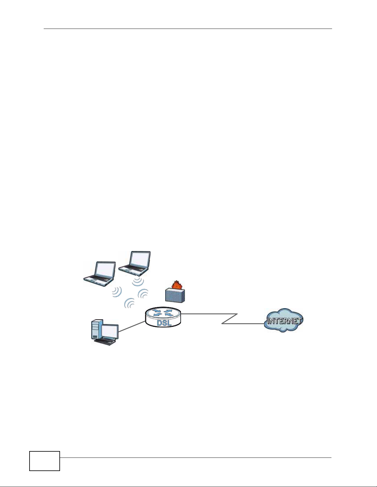
1.3 Internet Access
Your ZyXEL Device provides shared Internet access by connecting the DSL port to
the DSL or MODEM jack on a splitter or your telephone jack. Computers can
connect to the ZyXEL Device’s LAN port or wirelessly.
Figure 1 Internet Access Example
You can al so configure firewall and filtering feature on the ZyXEL Device for secure
Internet access. When the firewall is on, all incoming traffic from the Internet to
your network is blocked unless it is initiated from your network. This means that
probes from the outside to your network are not allowed, but you can safely
browse the Internet and download files.
22
Use the filtering feaure to block access to specific web sites or Internet
applications such as MSN or Yahoo Messanger. You can also configure IP/MAC
filtering rules for incoming or outgoing traffic.
P-660N-T1A User’s Guide
Use QoS to efficiently manage traffic on your network by giving priority to certain
types of traffic and/or to particular c omput ers. For example, you could make sure
that the ZyXEL Device gives Voice over Internet (VoIP) calls high priority, and/or
limit bandwidth devoted to the boss’s excessive file downloading.
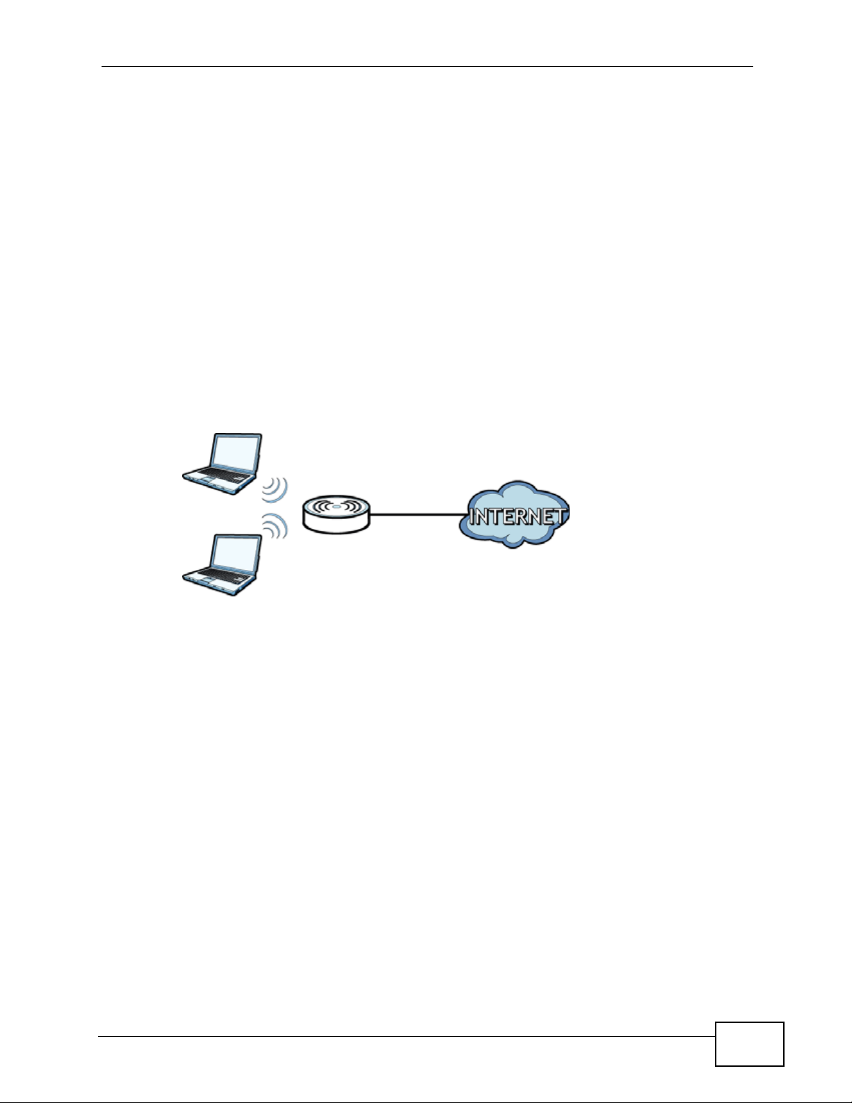
1.4 Wireless Access
The ZyXEL Device is a wireless Access Point (AP) for wireless clients, such as
notebook computers or PDAs and iPads. It allows them to connect to the Internet
without having to rely on inconvenient Ethernet cables.
You can configure your wireless network in either the built -in Web Configurator, or
using the WPS button.
Figure 2 Wireless Access Example
Chapter 1 Introduction
However, befo re you can use this ZyXEL Device to create a wireless network, you
must set its country code first in the Web Configurator. This is very important.
To set the wireless country code:
1 Log into the ZyXEL Device’s built-in Web Configurator. See Chapter 8 on page 99.
2 Open the Network > Wireless LAN > AP screen.
3 Select your country from the Channel Selection list. See Section 8.2 on page
101 for details.
4 Click Apply to save your changes.
5 Finally, open th e Int e rn et and Wireless Configuration wizards to set up your
network. See Chapter 5 on page 53.
P-660N-T1A User’s Guide
23
Chapter 1 Introduction
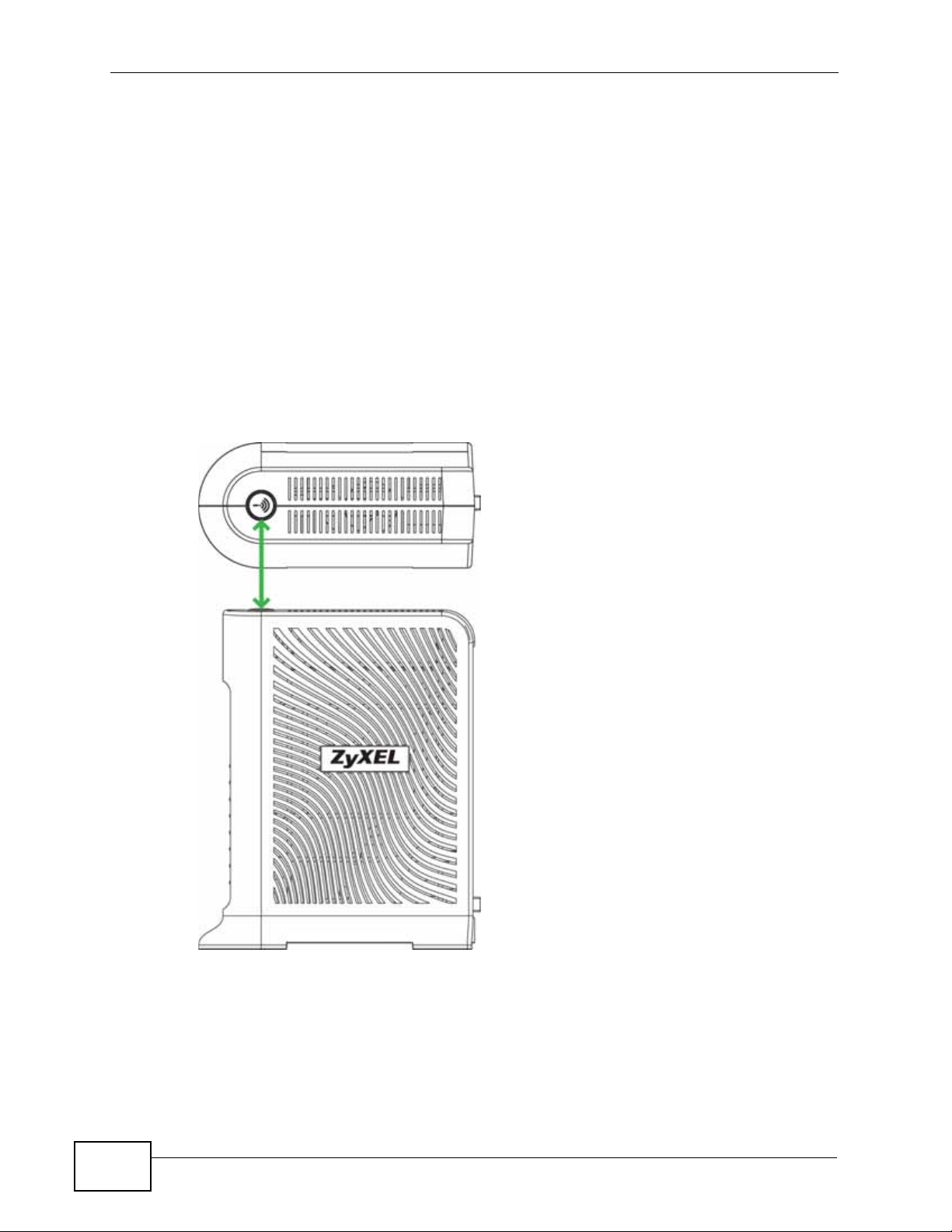
1.4.1 Using the WPS/WLAN Button
By default, the wireless network is turned off on the ZyXEL Device. To turn it on,
simply press the WPS/WLAN button on top of the device for 1 second. Once the
WPS/WLAN LED turns green, the wireless network is active.
You can also us e the WPS/WLAN button to quickly set up a secure wireless
connection between the ZyXEL Device and a WPS-compatible client by adding one
device at a time.
To activate WPS:
1 Make sure the POWER LED is on and not blinking.
2 Press the WPS/WLAN button for five to ten seconds and release it.
24
3 Press the WPS button on another WPS-enabled device within range of the ZyXEL
Device. The WPS/WLAN LED should flash while the ZyXEL Device sets up a WPS
connection with the other wireless device.
4 Once the connection is successfully made, the WPS/WLAN LEd shines green.
P-660N-T1A User’s Guide
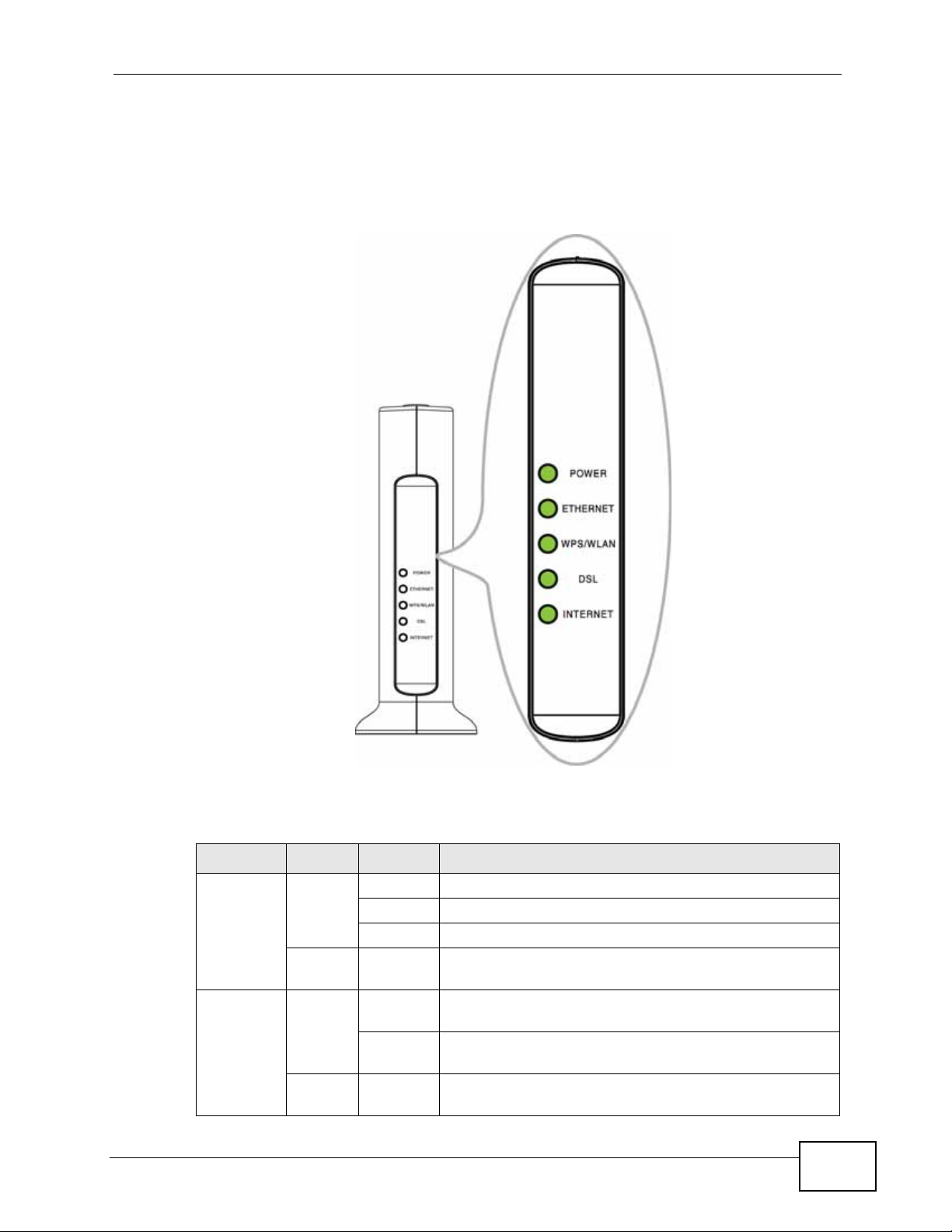
1.5 LEDs (Lights)
The following graphic displays the labels of the LEDs.
Figure 3 LEDs on the Front Panel
Chapter 1 Introduction
None of the LEDs are on if the ZyXEL Device is not receiving power.
Table 1 LED Descriptions
LED COLOR STATUS DESCRIPTION
POWER Green On The ZyXEL Device is receiving power and ready for use.
ETHERNET Green On The ZyXEL Device has an Ethernet connection with a
P-660N-T1A User’s Guide
Blinking The ZyXEL Device is self-testing.
Off The ZyXEL Device is not receiving power.
Red On The ZyXEL Device detected an error while self-testing,
or there is a device malfunction.
device on the Local Area Network (LAN).
Blinking The ZyXEL Device is sending/receiving data to /from
the LAN.
Off The ZyXEL Device does not have an Ethernet
connection with the LAN.
25

Chapter 1 Introduction
Table 1 LED Descriptions
LED COLOR STATUS DESCRIPTION
WPS/
WLAN
DSL Green On The DSL line is up.
INTERNET Green On The ZyXEL Device has an IP connection but no traffic.
Green On The wireless network is activated.
Blinking The ZyXEL Device is communicating with other
wireless clients.
Off The wireless network is not activated.
Orange Blinking The ZyXEL Device is setting up a WPS connection.
Blinking The ZyXEL Device is initializing the DSL line.
Off The DSL line is down.
Your device has a WAN IP address (either static or
assigned by a DHCP server), PPP negotiation was
successfully completed (if used) and the DSL
connection is up.
Blinking The ZyXEL Device is sending or receiving IP traffic.
Off The ZyXEL Device does not have an IP connection.
Red On The ZyXEL Device attempted to make an IP connection
but failed. Possible causes are no response from a
DHCP server, no PPPoE response, PPPoE authentication
failed.
Refer to the Quick Start Guide for information on hardware connections.
1.6 The RESET Button
If you forget your password or cannot access the web configurator, you will need
to use the RESET button at the back of the device to reload the factory-default
configuration file. This means that you will lose all configurations that you had
previously and the password will be reset to “1234”.
1.6.1 Using the Reset Button
1 Make sure the POWER LED is on (not blinking).
2 To set the device back to the factory default settings, press the RESET button for
ten seconds or until the POWER LED begins to blink and then release it. When the
POWER LED begins to blink, the defaults have been restored and the device
restarts.
26
P-660N-T1A User’s Guide

CHAPTER 2
The Web Configurator
2.1 Overview
The web configurator is an HTML-based management interface that allows easy
device setup and management via Internet browser. Use Internet Explorer 6.0 and
later or Netscape Navigator 7.0 and later versions. The recommended screen
resolution is 1024 by 768 pixels.
In order to use the web configurator you need to allow:
• Web browser pop -up windows from your device. W eb pop-up blocking is enabl ed
by default in Windows XP SP (Service Pack) 2.
• JavaScript (enabled by default).
• Java permissions (enabled by default).
See Appendix C on page 281 if you need to make sure these functions are allowed
in Internet Explorer.
2.1.1 Accessing the Web Configurator
1 Make sure your ZyXEL Device hardware is properly connected (refer to the Quick
Start Guide).
2 Launch your web browser.
3 Type "192.168.1.1" as the URL.
P-660N-T1A User’s Guide
27
Chapter 2 The Web Configurator
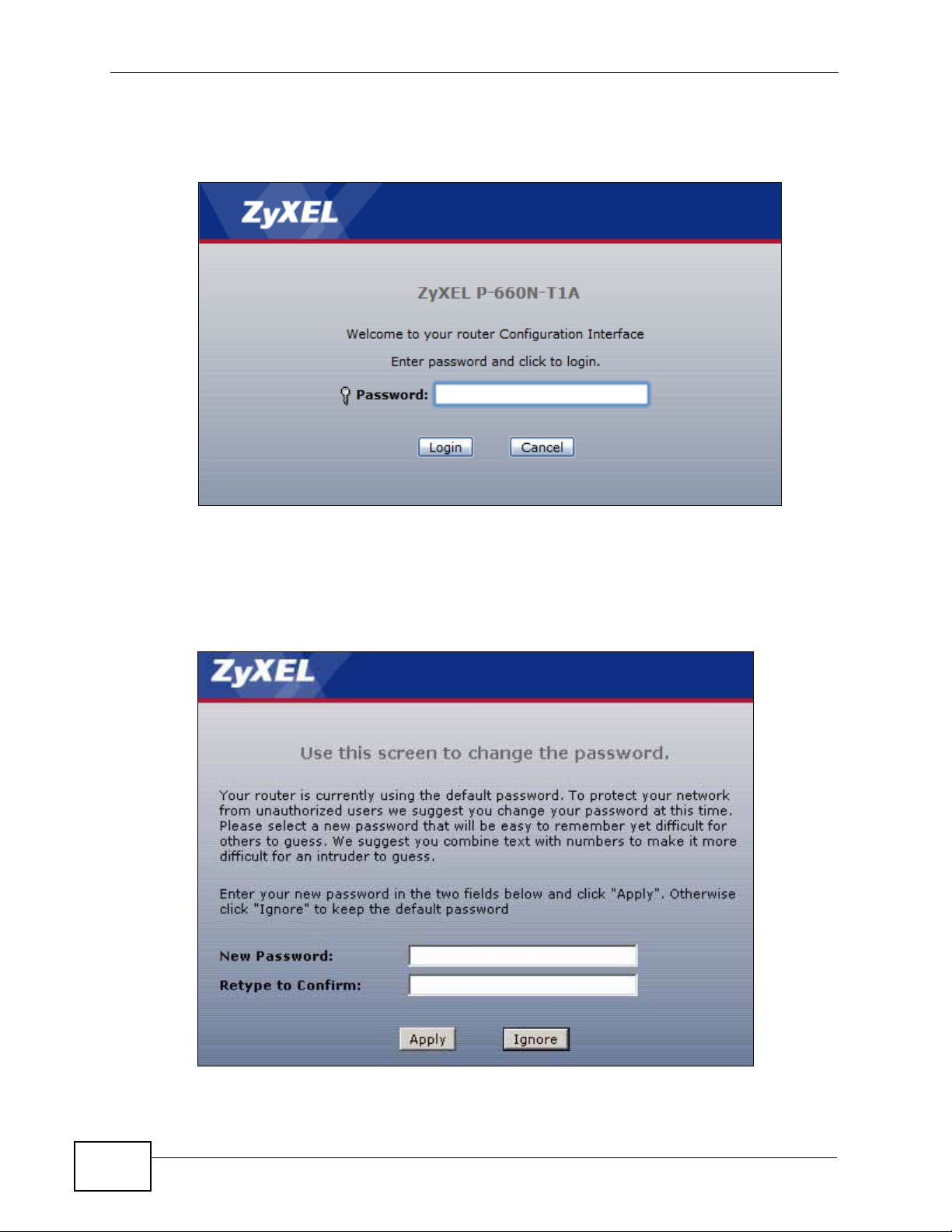
4 A password screen displays. Enter the admin password (1234 by default) in the
password screen and click Login.
Figure 4 Password Screen
5 The following screen displays if you have not yet changed your password. It is
strongly recommended you change the default password. Enter a new password,
retype it to confirm and click Apply; alternatively click Ignore to proceed to the
main menu if you do not want to change the password now.
Figure 5 Change Password Screen
28
P-660N-T1A User’s Guide
Chapter 2 The Web Configurator
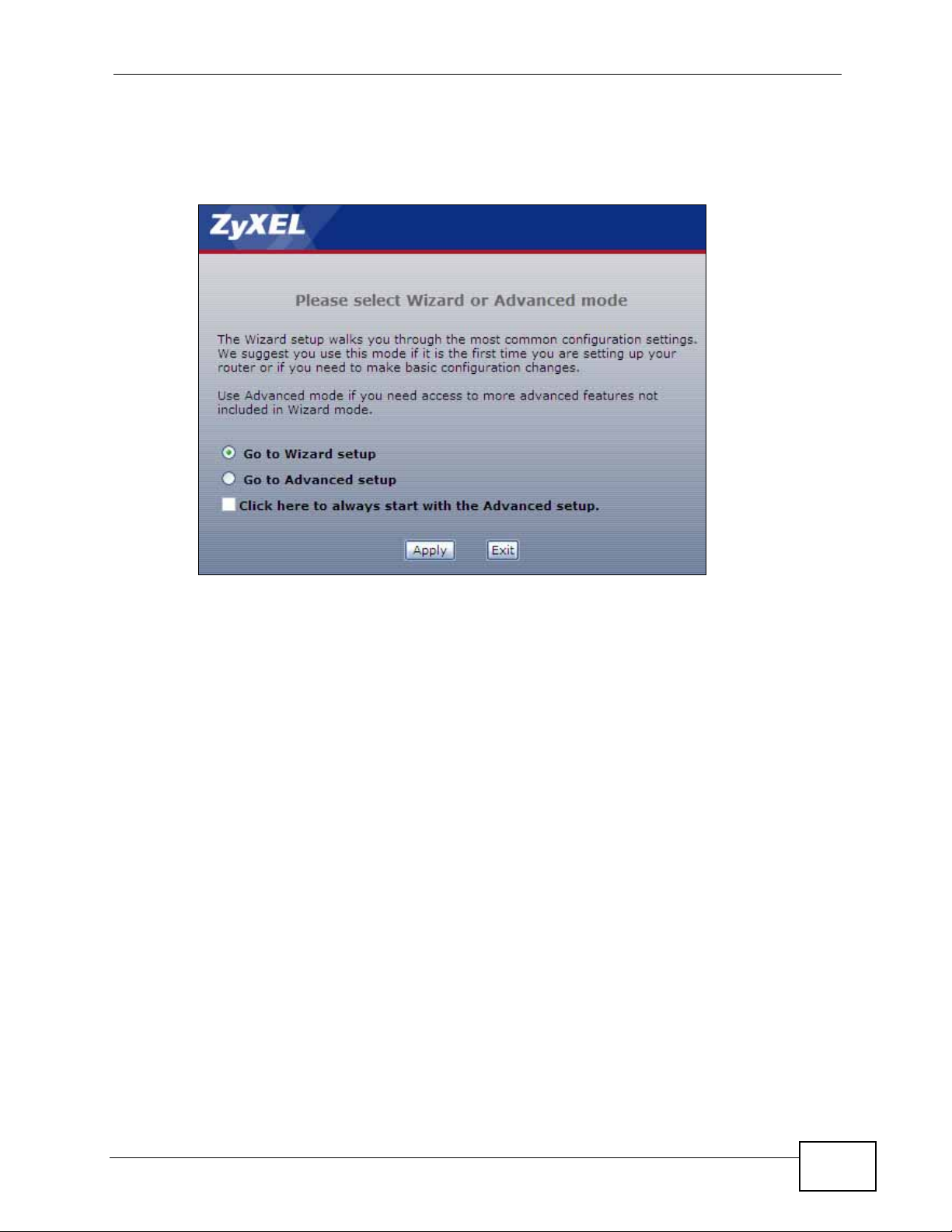
6 Select Go to Wizard setup and click Apply to display the wizard main screen.
Otherwise, select Go to Advanced setup and click Apply to display the Status
screen.
Figure 6 Replace Factory Default Certificate Screen
Note: For security reasons, the ZyXEL Device automatically logs you out if you d o not
use the web configurator for five minutes (default). If this happens, log in again.
P-660N-T1A User’s Guide
29
Chapter 2 The Web Configurator
B
C
D
A
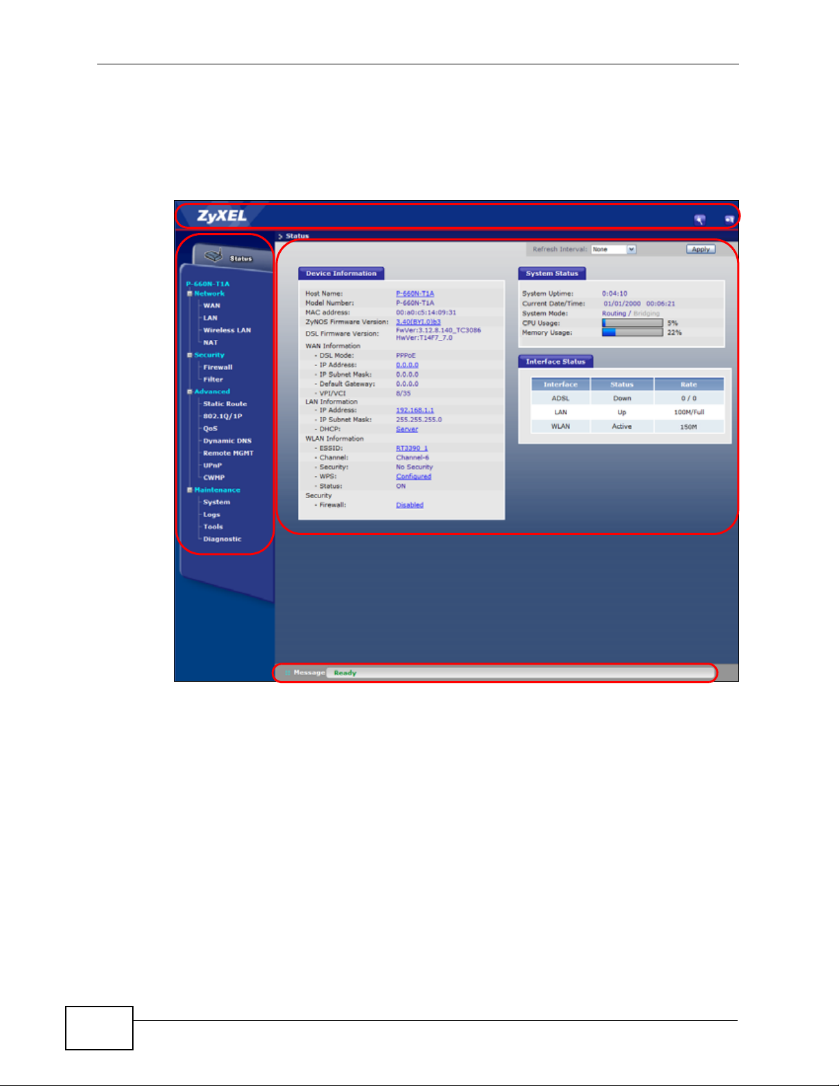
2.2 Main Screen
This section introduces the Web Configurator’s main screen.
Figure 7 Main Screen
The main screen is divided into these parts:
• A - title bar
• B - navigation panel
• C - main window
• D - status bar
30
P-660N-T1A User’s Guide

2.2.1 Title Bar
The title bar provides some icons in the upper right corner.
The icons provide the following functions.
Table 2 Web Configurator Icons in the Title Bar
ICON DESCRIPTION
Wizards: Click this icon to go to the configuration wizards. See Chapter
5 on page 53 for more information.
Logout: Click this icon to log out of the web configurator.
2.2.2 Navigation Panel
Use the menu items on the navigation panel to open screens to configure ZyXEL
Device features. The following tables describe each menu item.
Chapter 2 The Web Configurator
Table 3 Navigation Panel Summary
LINK TAB FUNCTION
Status This screen shows the ZyXEL Device’s general device and network
status information. Use this screen to access the statistics and
client list.
Network
WAN Internet
Connection
More
Connections
LAN IP Use this screen to configure LAN TCP/IP settings and other
DHCP Server Use this screen to configure LAN DHCP settings and DNS server.
Client List Use this screen to view current DHCP client information and to
IP Alias Use this screen to partition your LAN interface into subnets.
Use this screen to configure ISP parameters, WAN IP address
assignment, and other advanced properties.
Use this screen to configure additional WAN connections.
advanced properties.
always assign specific IP addresses to individual MAC addresses
(and host names).
P-660N-T1A User’s Guide
31

Chapter 2 The Web Configurator
Table 3 Navigation Panel Summary
LINK TAB FUNCTION
Wireless LAN AP Use this screen to configure the wireless LAN settings and WLAN
authentication/security settings.
More AP Use this screen to configure multiple BSSs on the ZyXEL Device.
WPS Use this screen to configure and view your WPS (Wi-Fi Protected
Setup) settings.
WPS Station Use this screen to set up a WPS wireless network.
WDS Use this screen to set up Wireless Distribution System links to
other access points.
Scheduling Use this screen to configure the dates/times to enable or disable
the wireless LAN.
NAT General Use this screen to enable NAT.
Port
Forwarding
ALG Use this screen to enable or disable SIP ALG.
Security
Firewall General Use this screen to activate/deactivate the firewall and SPI
Filter URL Use this screen to block access to certain web site URLs.
Application
Filter
IP/MAC Filter Use this screen to configure IP/MAC filtering rules for incoming or
Advanced
Static Route Use this screen to configure IP static routes to tell your device
802.1Q/1P Group Setting Use this screen to activate 802.1Q/1P, specify the management
Port Setting Use this screen to configure the PVID and assign traffic priority for
QoS General Use this screen to enable QoS and traffic prioritizing. Y ou can also
Dynamic DNS This screen allows you to use a static hostname alias for a
Use this screen to make your local servers visible to the outside
world.
(Security Parameter Index).
Use this screen to block or allow traffic from certain applications.
outgoing traffic.
about networks beyond the directly connected remote nodes.
VLAN group, display the VLAN groups and configure the settings
for each VLAN group.
each port.
configure the QoS rules and actions.
dynamic IP address.
32
P-660N-T1A User’s Guide

Chapter 2 The Web Configurator
Table 3 Navigation Panel Summary
LINK TAB FUNCTION
Remote
MGMT
UPnP General Use this screen to turn UPnP on or off.
CWMP Use this screen to have a management server manage the ZyXEL
Maintenance
System General Use this screen to configure your device’s password.
Logs Sys tem Log Use this screen to select which logs your device is to record.
Tools Firmware Use this screen to upload firmware to your device.
Diagnostic General Use this screen to test the connections to other devices.
WWW Use this screen to configure through which interface(s) and from
which IP address(es) users can use HTTP to manage the ZyXEL
Device.
Telnet Use this screen to configure through which interface(s) and from
which IP address(es) users can use Telnet to manage the ZyXEL
Device.
FTP Use this screen to configure through which interface(s) and from
which IP address(es) users can use FTP to access the ZyXEL
Device.
SNMP Use this screen to configure through which interface and from
which IP addresses(es) users can access the SNMP agent on the
ZyXEL Device.
DNS Use this screen to configure through which interface(s) and from
which IP address(es) users can send DNS queries to the ZyXEL
Device.
ICMP Use this screen to set whether or not your device will respond to
pings and probes for services that you have not made available.
Device.
Time and Date Use this screen to change your ZyXEL Device’s time and date.
Configuration Use this screen to backup and restore your device’s configuration
(settings) or reset the factory default settings.
Restart This screen allows you to reboot the ZyXEL Device without turning
the power off.
DSL Line This screen displays information to help you identify problems
with the DSL connection.
2.2.3 Main Window
The main window displays information and configuration fields. It is discussed in
the rest of this document.
Right after you log in, the Status screen is displayed. See Chapter 3 on page 35
for more information about the Status screen.
P-660N-T1A User’s Guide
33

Chapter 2 The Web Configurator
2.2.4 Status Bar
Check the status bar when you click Apply or OK to verify that the configuration
has been updated.
34
P-660N-T1A User’s Guide

CHAPTER 3
Status Screen
3.1 Overview
Use the Status screen to look at the current status of the device, system
resources, and interfaces (LAN and WAN). The Status screen also provides
information from DHCP and statistics from bandwidth management and traffic.
3.2 The Status Screen
Use this screen to view the status of the ZyXEL Device. Click Status to open this
screen.
Figure 8 Status Screen
P-660N-T1A User’s Guide
35

Chapter 3 Status Screen
Each field is described in the following table.
Table 4 Status Screen
LABEL DESCRIPTION
Refresh Interval Select how often you want the ZyXEL Device to update this screen.
Apply Click this to update this screen immediately.
Device Information
Host Name This field displays the ZyXEL Device system name. It is used for
Model
Number
MAC
Address
ZyNOS
Firmware
Version
DSL
Firmware
Version
WAN
Information
DSL Mode This is the DSL standard that your ZyXEL Device is using.
IP Address This is the current IP address of the ZyXEL Device in the WAN. Click this
IP Subnet
Mask
Default
Gateway
VPI/VCI This is the Virtual P ath Identifier and Virtual Channel Identifier that you
LAN
Information
IP Address This is the current IP address of the ZyXEL Device in the LAN. Click this
IP Subnet
Mask
DHCP This field displays what DHCP services the ZyXEL Device is providing to
identification.
This is the model name of your device.
This is the MAC (Media Access Control) or Ethernet address unique to
your ZyXEL Device.
This is the current version of the firmware inside the device. Click this
to go to the screen where you can change it.
This is the current version of the device’s DSL modem code.
to go to the screen where you can change it.
This is the current subnet mask in the WAN.
This is the IP address of the default gateway, if applicable.
entered in the wizard or WAN screen.
to go to the screen where you can change it.
This is the current subnet mask in the LAN.
the LAN. Choices are:
36
Server - The ZyXEL Device is a DHCP server in the LAN. It assigns IP
addresses to other computers in the LAN.
Relay - The ZyXEL Device acts as a surrogate DHCP server and relays
DHCP requests and responses between the remote server and the
clients.
None - The ZyXEL Device is not providing any DHCP services to the
LAN.
Click this to go to the screen where you can change it.
WLAN
Information
P-660N-T1A User’s Guide

Chapter 3 Status Screen
Table 4 Status Screen
LABEL DESCRIPTION
ESSID This is the descriptive name used to identify the ZyXEL Device in a
wireless LAN. Click this to go to the screen where you can change it.
Channel This is the channel number used by the ZyXEL Device now.
Security This displays the type of security mode the ZyXEL Device is using in the
wireless LAN.
WPS This displays whether WPS is activated. Click this to go to the screen
where you can configure the settings.
Status This displays whether WLAN is activated.
Security
Firewall This displays whether or not the ZyXEL Device’s firewall is activated.
Click this to go to the screen where you can change it.
System Status
System
Uptime
Current
Date/Time
System
Mode
CPU Usage This field displays what percentage of the ZyXEL Device’s processing
Memory
Usage
Interface Status
Interface This column displays each interface the ZyXEL Device has.
This field displays how long the ZyXEL Device has been running since it
last started up. The ZyXEL Device starts up when you plug it in, when
you restart it (Maintenance > Tools > Restart), or when you reset it.
This field displays the current date and time in the ZyXEL Device. You
can change this in Maintenance > System > Time Setting.
This displays whether the ZyXEL Device is functioning as a router or a
bridge.
ability is currently used. When this percentage is close to 100%, the
ZyXEL Device is running at full load, and the throughput is not going to
improve anymore. If you want some applications to have more
throughput, you should turn off other applications (for example, using
QoS; see Chapter 14 on page 169).
This field displays what percentage of the ZyXEL Device’s memory is
currently used. Usually, this percentage should not increase much. If
memory usage does get close to 100%, the ZyXEL Device is probably
becoming unstable, and you should restart the device. See Section 21.4
on page 223, or turn off the device (unplug the power) for a few
seconds.
P-660N-T1A User’s Guide
37

Chapter 3 Status Screen
Table 4 Status Screen
LABEL DESCRIPTION
Status This field indicates whether or not the ZyXEL Device is using the
Rate For the LAN interface, this displays the port speed and duplex setting.
interface.
For the DSL interface, this field displays Down (line is down), Up (line
is up or connected) if you're using Ethernet encapsulation and Down
(line is down), Up (line is up or connected), Idle (line (ppp) idle), Dial
(starting to trigger a call) and Drop (dropping a call) if you're using
PPPoE encapsulation.
For the LAN interface, this field displays Up when the ZyXEL Device is
using the interface and Down when the ZyXEL Device is not using the
interface.
For the WLAN interface, it displays Active when WLAN is enabled or
InActive when WLAN is disabled.
For the DSL interface, it displays the downstream and upstream
transmission rate.
For the WLAN interface, it displays the maximum transmission rate
when WLAN is enabled or N/A when WLAN is disabled.
38
P-660N-T1A User’s Guide

CHAPTER 4
Tutorials
4.1 Overview
This chapter shows you how to use the ZyXEL Device’s various features.
• Setting Up a Secure Wireless Network, see page 39
• Configuring the MAC Address Filter, see page 46
• Multiple WAN Connections Example, see page 48
4.2 Setting Up a Secure Wireless Network
Thomas wants to set up a wireless network so that he can use his notebook to
access the Internet. In this wireless network, the ZyXEL Device serves as an
access point (AP), and the notebook is the wireless client. The wireless client can
access the Internet through the AP.
Thomas has to configure the wireless network settings on the ZyXEL Device. Then
he can set up a wireless network using WPS (Section 4.2.2 on page 41) or manual
configuration (Section 4.2.3 on page 45).
4.2.1 Configuring the Wireless Network Settings
This example uses the following parameters to set up a wireless network.
SSID Example
Security Mode WPA-PSK
Pre-Shared Key 1234567key7654321yek
802.11 Mode 802.11b+g+n
P-660N-T1A User’s Guide
39

Chapter 4 Tutorials
1 Click Network > Wireless LAN to open the AP screen. Configure the screen
using the provided parameters (see page 39). Click Apply.
2 Click the Advanced Setup button and select 802.11b+g+n in the 802.11 Mode
field. Click Apply.
Thomas can now use the WPS feature to establish a wireless connection between
his notebook and the ZyXEL Device (see Section 4.2.2 on page 41). He can also
use the notebook’s wireless client to search fo r the ZyXEL Device (see Section
4.2.3 on page 45).
40
P-660N-T1A User’s Guide

4.2.2 Using WPS
This section shows you how to set up a wireless network using WPS. It uses the
ZyXEL Device as the AP and ZyXEL NWD210N as the wireless client which
connects to the notebook.
Note: The wireless client must be a WPS-aware device (for example, a WPS USB
adapter or PCMCIA card).
There are two WPS methods to set up the wireless client settings:
• Push Button Configuration (PBC) - simply press a button. This is the easier
of the two methods.
• PIN Configuration - configure a Personal Identification Number (PIN) on the
ZyXEL Device. A wireless client must also use the same PIN in order to
download the wireless network settings from the ZyXEL Device.
Push Button Configuration (PBC)
Chapter 4 Tutorials
1 Make sure that your ZyXEL Device is turned on and your notebook is within the
cover range of the wireless signal.
2 Make sure that you have installed the wireless client driver and utility in your
notebook.
3 In the wireless client utility, go to the WPS setting page. Enable WPS and press
the WPS button (Start or WPS button).
4 Push and hold the WPS button located on the ZyXEL Device’s rear panel for more
than 5 seconds. Alternatively, you may log into ZyXEL Device’s web configurator
and click the Push Button in the Network > Wireless LAN > WPS Station
screen.
Note: Your ZyXEL Device has a WPS button located on its rear panel as well as a
WPS button in its configuration utility. Both buttons have exactly the same
function: you can use one or the other.
P-660N-T1A User’s Guide
41

Chapter 4 Tutorials
Wireless Client
ZyXEL Device
SECURITY INFO
COMMUNICATION
WITHIN 2 MINUTES
Press and hold for
5 seconds
Note: It doesn’t matter which button is pressed first. You must press the second
The ZyXEL Device sends the proper configuration settings to the wireless client.
This may take up to two minutes. The wireless client is then able to communicate
with the ZyXEL Device securely.
The following figure shows you an example of how to set up a wireless network
and its security by pressing a button on both ZyXEL Device and wireless client.
Example WPS Process: PBC Method
button within two minutes of pressing the first one.
42
P-660N-T1A User’s Guide

Chapter 4 Tutorials
PIN Configuration
When you use the PIN configuration method, you need to use both the ZyXEL
Device’s web configurator and the wireless client’s utility.
1 Launch your wireless client’s configuration utility. Go to the WPS settings and
select the PIN method to get a PIN number.
2 Enter the PIN number in the PIN field in the Network > Wireless LAN > WPS
Station screen on the ZyXEL Device.
3 Click the Start buttons (or the button next to the PIN field) on both the wireless
client utility screen and the ZyXEL Device’s WPS Station screen within two
minutes.
The ZyXEL Device authenticates the wireless client and sends the proper
configuration settings to the wireless client. This may tak e up to two minutes. The
wireless client is then able to communicate with the ZyXEL Device securely.
P-660N-T1A User’s Guide
43

Chapter 4 Tutorials
Authentication by PIN
SECURITY INFO
WITHIN 2 MINUTES
Wireless Client
ZyXEL Device
COMMUNICATION
The following figure shows you how to set up a wireless network and its security
on a ZyXEL Device and a wireless client by using PIN method.
Example WPS Process: PIN Method
44
P-660N-T1A User’s Guide

4.2.3 Without WPS
Use the wireless adapter’s utility installed on the notebook to search for the
“Example” SSID. Then enter the “DoNotStealMyWirelessNetwork” pre-shared key
to establish an wireless Internet connection.
Note: The ZyXEL Device supports IEEE 802.11b and IEEE 802.11g wireless clients.
Make sure that your notebook or computer’s wireless adapter supports one of
these standards.
4.2.4 Setting Up Wireless Network Scheduling
Thomas mostly uses his notebook to access the Internet on weekends;
occasionally he uses it at night on weekdays. Here is how Thomas can set up a
schedule to turn on the wireless network at specific time and days.
1 Click Network > Wireless Network > Scheduling to open the following screen.
Chapter 4 Tutorials
P-660N-T1A User’s Guide
45

Chapter 4 Tutorials
Thomas
Josephine
2 Configure the screen as follows. Turn on the wireless network from Mondays to
Fridays between 18:00 and 23:30. Turn on the wireless network all day on
Saturdays and Sundays. Click Apply.
4.3 Configuring the MAC Address Filter
Thomas noticed that his daughter Josephine spends too m uch time surfing the
web and downloading media files. He decided to prevent Josephine from accessing
the Internet so that she can concentrate on preparing for her final exams.
Josephine’s computer connects wirelessly to the Internet through the ZyXEL
Device. Thomas can deny access to the wireless network using the MAC address of
Josephine’s computer.
46
P-660N-T1A User’s Guide

Chapter 4 Tutorials
1 Click Network > LAN > Client List to open the following screen. Look for the
MAC address of Josephine’s computer.
2 Click Network > Wireless LAN to open the AP screen. Click the Edit button in
the MAC Filter field.
P-660N-T1A User’s Guide
47

Chapter 4 Tutorials
3 Select Active MAC Filter and Deny Filter Action. Enter the MAC address you
found in the Client List screen. Click Apply.
Josephine will no longer be able to access the Internet through the ZyXEL Device.
4.4 Multiple WAN Connections Example
This example shows an application for multiple WAN connections.
Your ISP may configure more than one WAN connection on the ZyXEL Device to
record traffic statistics or calculate service charges.
In Figure 9, three WAN connections are configured over the ADSL line:
• The connection with VPI/VCI, 0/33, is dedicated for Media-On-Demand (MOD)
service.
• The connection with VPI/VCI, 0/34, is dedicated for VoIP service.
48
P-660N-T1A User’s Guide

Chapter 4 Tutorials
• The connection with VPI/VCI, 0/35, is dedicated for general data transmission.
Figure 9 Example for Multiple WAN Connections
P-660N-T1A User’s Guide
49

Chapter 4 Tutorials
50
P-660N-T1A User’s Guide

PART II
Technical Reference
51

52

CHAPTER 5
Internet and Wireless Setup
Wizard
5.1 Overview
Use the wizard setup screens to configure your system for Internet access with
the information given to you by your ISP.
Note: See the advanced menu chapters for background information on these fields.
5.2 Internet Access Wizard Setup
1 After you enter the password to access the web configurator, select Go to Wizard
setup and click Apply. Otherwise, click the wizard icon i n th e top ri ght corner of
the web configurator to go to the wizards.
Figure 10 Select a Mode
P-660N-T1A User’s Guide
53

Chapter 5 Internet and Wireless Setup Wizard
2 Click INTERNET/WIRELESS SETUP to configure the system for Internet access
and wireless connection.
Figure 11 Wizard Welcome
3 Your ZyXEL device attempts to detect your DSL connection and your connection
type.
3a The following screen appears if a connection is not detected. Check your
hardware connections and click Restart the INTERNET/WIRELESS SETUP
Wizard to return to the wizard welcome screen. If you still cannot connect,
click Manually configure your Internet connection. Follow the directions
in the wizard and enter your Internet setup information as provided to you by
your ISP. See Section 5.2.1 on page 56 for more details.
If you would like to skip your Internet setup and configure the wireless LAN
settings, leave Yes selected and click Next.
Figure 12 Auto Detection: No DSL Connection
54
P-660N-T1A User’s Guide

Chapter 5 Internet and Wireless Setup Wizard
3b The following screen displays if a PPPoE or PPPoA connection is detected.
Enter your Internet account information (username, password and/or service
name) exactly as provided by your ISP. Then click Next and see Section 5.3 on
page 62 for wireless connection wizard setup.
Figure 13 Auto-Detection: PPPoE
3c The following screen appears if the ZyXEL device detects a connection but not
the connection type. Click Next and refer to Section 5.2.1 on page 56 on how
to manually configure the ZyXEL Device for Internet access.
Figure 14 Auto Detection: Failed
P-660N-T1A User’s Guide
55

Chapter 5 Internet and Wireless Setup Wizard
5.2.1 Manual Configuration
1 If the ZyXEL Device fails to detect your DSL connection type but the physical line
is connected, enter your Internet access information in the wizard screen exactly
as your service provider gave it to you. Leave the defaults in any fields for which
you were not given informat ion.
Figure 15 Internet Access Wizard Setup: ISP Parameters
56
The following table describes the fields in this screen.
Table 5 Internet Access Wizard Setup: ISP Parameters
LABEL DESCRIPTION
Mode Select Routing (default) from the drop-down list box if your ISP give you
one IP address only and you want multiple computers to share an Internet
account. Select Bridge when your ISP provides you more than one IP
address and you want the connected computers to get individual IP
address from ISP’s DHCP server directly. If you select Bridge, you cannot
use Firewall, DHCP server and N AT on the ZyXEL Device.
Encapsulation Select the encapsulation type your ISP uses from the Encapsulation
drop-down list box. Choices vary depending on what you select in the
Mode field.
If you select Bridge in the Mode field, select either PPPoA or RFC 1483.
If you select Routing in the Mode field, select PPPoA, RFC 1483, ENET
ENCAP or PPPoE.
P-660N-T1A User’s Guide

Chapter 5 Internet and Wireless Setup Wizard
Table 5 Internet Access Wizard Setup: ISP Parameters
LABEL DESCRIPTION
Multiplexing Select the multiplexing method used by your ISP from the Multiplex
drop-down list box either VC-based or LLC-based.
Virtual Circuit IDVPI (Virtual Path Identifier) and VCI (Virtual Channel Identifier) define a
virtual circuit. Refer to the appendix for more information.
VPI Enter the VPI assigned to you. This field may already be configured.
VCI Enter the VCI assigned to you. This field may already be configured.
Back Click this to return to the previous screen without saving.
Next Click this to continue to the next wizard screen. The next wizard screen
you see depends on what protocol you chose above.
Exit Click this to close the wizard screen without saving.
2 The next wizard screen varies depending on what mode and encapsulation type
you use. All screens shown are with routing mode. Configure the fields and click
Next to continue. See Section 5.3 on page 62 for wireless connection wizard
setup
Figure 16 Internet Connection with PPPoE
P-660N-T1A User’s Guide
57

Chapter 5 Internet and Wireless Setup Wizard
The following table describes the fields in this screen.
Table 6 Internet Connection with PPPoE
LABEL DESCRIPTION
User Name Enter the user name exactly as your ISP assigned. If assigned a name in
the form user@domain where domain identifies a service name, then e nter
both components exactly as given.
Password Enter the password associated with the user name above.
Service
Name
Back Click this to return to the previous screen without saving.
Apply Click this to save your changes.
Exit Click this to close the wizard screen without saving.
Type the name of your PPPoE service here.
Figure 17 Internet Connection with RFC 1483
58
P-660N-T1A User’s Guide

Chapter 5 Internet and Wireless Setup Wizard
The following table describes the fields in this screen.
Table 7 Internet Connection with RFC 1483
LABEL DESCRIPTION
IP Address This field is available if you select Routing in the Mode field.
Type your ISP assigned IP address in this field.
Back Click this to return to the previous screen without saving.
Next Click this to continue to the next wizard screen.
Exit Click this to close the wizard screen without saving.
Figure 18 Internet Connection with ENET ENCAP
P-660N-T1A User’s Guide
59

Chapter 5 Internet and Wireless Setup Wizard
The following table describes the fields in this screen.
Table 8 Internet Connection with ENET ENCAP
LABEL DESCRIPTION
Obtain an IP
Address
Automatically
Static IP
Address
IP Address Enter your ISP assigned IP address.
Subnet Mask Enter a subnet mask in dotted decimal notation.
Gateway IP
address
First DNS
Server
Second DNS
Server
Back Click this to return to the previous screen without saving.
Apply Click this to save your changes.
Exit Click this to close the wizard screen without saving.
A static IP address is a fixed IP that your ISP gives you. A dynamic IP
address is not fixed; the ISP assigns you a different one each time you
connect to the Internet.
Select Obtain an IP Address Automatically if you have a dynamic IP
address.
Select Static IP Address if your ISP gave you an IP address to use.
Refer to the appendix to calculate a subnet mask If you are implementing
subnetting.
You must specify a gateway IP address (supplied by your ISP) when you
use ENET ENCAP in the Encapsulation field in the previous screen.
Enter the IP addresses of the DNS servers. The DNS servers are passed to
the DHCP clients along with the IP address and the subnet mask.
As above.
Figure 19 Internet Connection with PPPoA
60
P-660N-T1A User’s Guide

Chapter 5 Internet and Wireless Setup Wizard
The following table describes the fields in this screen.
Table 9 Internet Connection with PPPoA
LABEL DESCRIPTION
User Name Enter the login name that your ISP gives you.
Password Enter the password associated with the user name above.
Back Click this to return to the previous screen without saving.
Apply Click this to save your changes.
Exit Click this to close the wizard screen without saving.
• If the user name and/or password you entered for PPPoE or PPPoA connection
are not correct, the screen displays as shown next. Click Back to Username
and Password setup to go back to the screen where you can modify them.
Figure 20 Connection Te st Failed-1
• If the following screen displays, check if your account is activated or click
Restart the Internet/Wireless Setup Wizard to verify your Internet access
settings.
Figure 21 Connection Test Failed-2.
P-660N-T1A User’s Guide
61

Chapter 5 Internet and Wireless Setup Wizard
5.3 Wireless Connection Wizard Setup
After you configure the Internet access information, use the following screens to
set up your wireless LAN.
1 Select Yes and clic k Next to configure wireless settings. Otherwise, select No and
skip to Step 6.
Figure 22 Connection Test Successful
2 Use this screen to activate the wireless LAN. Click Next to continue.
Figure 23 Wireless LAN Setup Wizard 1
The following table describes the labels in this screen.
Table 10 Wireless LAN Setup Wizard 1
LABEL DESCRIPTION
Active Select the check box to turn on the wireless LAN.
Back Click this to return to the previous screen without saving.
62
P-660N-T1A User’s Guide

Chapter 5 Internet and Wireless Setup Wizard
Table 10 Wireless LAN Setup Wizard 1
LABEL DESCRIPTION
Next Click this to continue to the next wizard screen.
Exit Click this to close the wizard screen without saving.
3 Configure your wireless settings in this screen. Click Next.
Figure 24 Wireless LAN
The following table describes the labels in this screen.
Table 11 Wireless LAN Setup Wizard 2
LABEL DESCRIPTION
Network
Name(SSID)
Channel
Selection
Security Select Manually assign a WPA-PSK key to configure a Pre-Shared Key
Back Click thi s to return to the previous screen without saving.
Enter a descriptive name (up to 32 printable 7-bit ASCII characters) for the
wireless LAN.
If you change this field on the ZyXEL Device, make sure all wireless
stations use the same SSID in order to access the network.
The range of radio frequencies used by IEEE 802.11b/g wireless devices is
called a channel. Select a channel ID that is not already in use by a
neighboring device.
(WPA-PSK). Choose this option only if your wireless clients support WPA.
See Section 5.3.1 on page 64 for more information.
Select Manually assign a WEP key to configure a WEP Key. See Section
5.3.2 on page 65 for more information.
Select Disable wireless security to have no wireless LAN security
configured and your network is accessible to any wireless networking
device that is within range.
P-660N-T1A User’s Guide
63

Chapter 5 Internet and Wireless Setup Wizard
Table 11 Wireless LAN Setup Wizard 2
LABEL DESCRIPTION
Next Click this to continue to the next wizard screen.
Exit Click this to close the wizard screen without saving.
Note: The wireless stations and ZyXEL Device must use the same SSID, channel ID
and WEP encryption key (if WEP is enabled), WPA-PSK (if WPA-PSK is
enabled) for wireless communication.
4 This screen varies depending on the security mode you selected in the previous
screen. Fill in the field (if available) and click Next.
5.3.1 Manually Assign a WPA-PSK key
Choose Manually assign a WPA-PSK key in the Wireless LAN setup screen to
set up a Pre-Shared Key.
Figure 25 Manually Assign a WPA-PSK key
64
The following table describes the labels in this screen.
Table 12 Manually Assign a WPA-PSK key
LABEL DESCRIPTION
Pre-Shared
Key
Back Click thi s to return to the previous screen without saving.
Next Click this to continue to the next wizard screen.
Exit Click this to close the wizard screen without saving.
T ype from 8 to 63 case-sensitive ASCII characters. You can set up the most
secure wireless connection by configuring WPA in the wireless LAN screens.
You need to configure an authentication server to do this.
P-660N-T1A User’s Guide

5.3.2 Manually Assign a WEP Key
Choose Manually assign a WEP key to setup WEP Encryption parameters.
Figure 26 Manually Assign a WEP key
Chapter 5 Internet and Wireless Setup Wizard
The following table describes the labels in this screen.
Table 13 Manually Assign a WEP key
LABEL DESCRIPTION
Key The WEP keys are used to encrypt data. Both the ZyXEL Device and the
wireless stations must use the same WEP key for data transmission.
Enter any 5 or 13 ASCII characters, or 10 or 26 hexadecimal characters
("0-9", "A-F") for a 64-bit or 128-bit WEP key respectively.
Back Click thi s to return to the previous screen without saving.
Next Click this to continue to the next wizard screen.
Exit Click this to close the wizard screen without saving.
5 Click Apply to save your wireless LAN settings.
Figure 27 Wireless LAN Setup 3
P-660N-T1A User’s Guide
65

Chapter 5 Internet and Wireless Setup Wizard
6 Use the read-only summary table to check whether what you have configured is
correct. Click Finish to complete and save the wizard setup.
Note: No wireless LAN settings display if you chose not to configure wireless LAN
settings.
Figure 28 Internet Access and WLAN Wizard Setup Complete
7 Launch your web browser and navigate to www .zyxel.com. Internet access is just
the beginning. Refer to the rest of this guide for more detailed information on the
complete range of Z yXEL Device features. If you cannot access the Internet, open
the web configurator again to conf irm th at the Internet setti ngs y ou configured in
the wizard setup are correct.
66
P-660N-T1A User’s Guide

CHAPTER 6
WAN
LAN
WAN Setup
6.1 Overview
This chapter describes how to configure WAN settings from the WAN screens. Use
these screens to configure your ZyXEL Device for Internet access.
A WAN (Wide Area Network) connection is an outside connection to another
network or the Internet. It connects your private networks (such as a LAN (Local
Area Network) and other networks, so that a computer in one location can
communicate with computers in other locations.
Figure 29 LAN and WAN
6.1.1 What You Can Do in the WAN Screens
•Use the Internet Connection screen (Section 6.2 on page 69) to configure the
WAN settings on the ZyXEL Device for Internet access.
•Use the More Connections screen (Section 6.3 on page 74) to set up
additional Internet access connections.
6.1.2 What You Need to Know
The following terms and concepts may help as you this chapter.
Encapsulation Method
Encapsulation is used to include data from an upper layer protocol into a lower
layer protocol. To set up a WAN connection to the Internet, you need to use the
same encapsulation method used by your ISP (Internet Service Provider). If your
ISP offers a dial-up Internet connection using PPPoE (PPP over Ethernet) or PPPoA,
P-660N-T1A User’s Guide
67

Chapter 6 WAN Setup
they should also provide a username and password (and service name) for user
authentication.
WAN IP Address
The WAN IP address is an IP address for the ZyXEL Device, which makes it
accessible from an outside network. It is used by the ZyXEL Device to
communicate with other devices in other networks. It can be static (fixed) or
dynamically assigned by the ISP each time the ZyXEL Device tries to access the
Internet.
If your ISP assigns you a static WAN IP address, they should also assign you the
subnet mask and DNS server IP address(es) (and a gateway IP add ress if you use
the Ethernet or ENET ENCAP encapsulation method).
Multicast
Traditionally, IP packets are transmitted in one of either two ways - Unicast (1
sender - 1 recipient) or Broadcast (1 sender - everybody on the network).
Multicast delivers IP packets to a group of hosts on the network - not everybody
and not just one.
IGMP
IGMP (Internet Group Multicast Protocol) is a network-layer protocol used to
establish membership in a Multicast group - it is not used to carry user data.
There are three versions of IGMP. IGMP version 2 and 3 are improvements over
version 1, but IGMP version 1 is still in wide use.
Finding Out More
See Section 6.4 on page 78 for technical background information on WAN.
6.1.3 Before You Begin
You need to know your Internet access settings such as encapsulation and W AN IP
address. Get this information from your ISP.
68
P-660N-T1A User’s Guide

6.2 The Internet Connection Screen
Use this screen to change your ZyXEL Device’s WAN settings. Click Network >
WAN > Internet Connection. The screen differs by the WAN type and
encapsulation you select.
Figure 30 Network > WAN >Internet Connection (PPPoE)
Chapter 6 WAN Setup
P-660N-T1A User’s Guide
69

Chapter 6 WAN Setup
The following table describes the labels in this screen.
Table 14 Network > WAN > Internet Connection
LABEL DESCRIPTION
Line
ADSL Mode Select the mode supported by your ISP.
ADSL Type Select the type supported by your ISP.
General
Mode Select Routing (default) from the drop-down list box if your ISP gives
Encapsulation Select the method of encapsulation used by your ISP from the drop-
Use Auto Sync-Up if you are not sure which mode to choose from.
The ZyXEL Device dynamically diagnoses the mode supported by the
ISP and selects the best compatible one for your connection.
Other options are ADSL2+, ADSL2, G.DMT, T1.413 and G.lite.
Available options are ANNEX A, ANNEX A/L, ANNEX M and ANNEX
A/L/M.
you one IP address only and you want multiple computers to share an
Internet account. Select Bridge when your ISP provides you more
than one IP address and you want the connected computers to get
individual IP address from ISP’s DHCP server directly. If you select
Bridge, you cannot use Firewall, DHCP server and NAT on the ZyXEL
Device.
down list box. Choices vary depending on the mode you select in the
Mode field.
If you select Bridge in the Mode field, select either PPPoA or RFC
1483.
If you select Routing in the Mode field, select PPPoA, RFC 1483,
ENET ENCAP or PPPoE.
User Name (PPPoA and PPPoE encapsulation only) Enter the user name exactly as
your ISP assigned. If assigned a name in the form user@domain
where domain identifies a service name, then enter both components
exactly as given.
Password (PPPoA and PPPoE encapsulation only) Enter the password associated
with the user name above.
Service Name (PPPoE only) Type the name of your PPPoE service here.
Multiplexing Select the method of multiplexing used by your ISP from the drop-
down list. Choices are VC or LLC.
This field is not available if you set the WAN type to Ethernet.
Virtual Circuit ID VPI (Virtual Path Identifier) and VCI (Virtual Channel Identifier) define
a virtual circuit. Refer to the appendix for more information.
These fields are not available if you set the WAN type to Ethernet.
VPI The valid range for the VPI is 0 to 255. Enter the VPI assigned to you.
VCI The valid range for the VCI is 32 to 65535 (0 to 31 is reserved for
local management of ATM traffic). Enter the VCI assigned to you.
70
P-660N-T1A User’s Guide

Chapter 6 WAN Setup
Table 14 Network > WAN > Internet Connection (continued)
LABEL DESCRIPTION
IP Address This option is available if you select Routing in the Mode field.
A static IP address is a fixed IP that your ISP gives you. A dynamic IP
address is not fixed; the ISP assigns you a different one each time you
connect to the Internet.
Select Obtain an IP Address Automatically if you have a dynamic
IP address; otherwise select Static IP Address and type your ISP
assigned IP address in the IP Address field below .
Subnet Mask This option is available if you select ENET ENCAP in the
Encapsulation field.
Enter a subnet mask in dotted decimal notation.
ENET ENCAP
Gateway
Connection (PPPoA and PPPoE encapsulation only)
Keep Alive Select Keep Alive when you want your connection up all the time.
Connect on
Demand
Max Idle Timeout Specify an idle time-out in the Max Idle Timeout field when you
Apply Click this to save your changes.
Cancel Click this to restore your previously saved settings.
Advanced Setup Click this to display the Advanced WAN Setup screen and edit more
This option is available if you select ENET ENCAP in the
Encapsulation field.
Specify a gateway IP address (supplied by your ISP).
The ZyXEL Device will try to bring up the connection automatically if it
is disconnected.
Select Connect on Demand when you don't want the connection up
all the time and specify an idle time-out in the Max Idle Timeout
field.
select Connect on Demand. The default setting is 0, which means
the Internet session will not timeout.
details of your WAN setup.
P-660N-T1A User’s Guide
71

Chapter 6 WAN Setup
6.2.1 Advanced Setup
Use this screen to edit your ZyXEL Device's advanced WAN settings. Click the
Advanced Setup button in the Internet Connection screen. The screen
appears as shown.
Figure 31 Network > WAN > Internet Connection: Advanced Setup
72
The following table describes the labels in this screen.
Table 15 Network > WAN > Internet Connection: Advanced Setup
LABEL DESCRIPTION
RIP & Multicast
Setup
RIP Direction RIP (Routing Information Protocol) allows a router to exchange
RIP Version This field is not configurable if you select None in the RIP Direction
This section is not available when you configure the ZyXEL Device to
be in bridge mode.
routing information with other routers. Use this field to control how
much routing information the ZyXEL Device sends and receives on the
subnet.
Select the RIP direction from None, Both, In Only and Out Only.
field.
Select the RIP version from RIP-1, RIP-2B and RIP-2M.
P-660N-T1A User’s Guide

Chapter 6 WAN Setup
Table 15 Network > WAN > Internet Connection: Advanced Setup (continued)
LABEL DESCRIPTION
Multicast Multicast packets are sent to a group of computers on the LAN and are
an alternative to unicast packets (packets sent to one computer) and
broadcast packets (packets sent to every computer).
Internet Group Multicast Protocol (IGMP) is a network-layer protocol
used to establish membership in a multicast group. The ZyXEL Device
supports IGMP-v1, IGMP-v2 and IGMP-v3. Select None to disable
it.
ATM QoS
ATM QoS Type Select CBR (Continuous Bit Rate) to specify fixed (always-on)
bandwidth for voice or data traffic. Select UBR (Unspecified Bit Rate)
for applications that are non-time sensitive, such as e-mail. Select
rtVBR (real-time Variable Bit Rate) type for applications with bursty
connections that require closely controlled delay and delay variation.
Select nrtVBR (non real-time Variable Bit Rate) type for connections
that do not require closely controlled delay and delay variation.
Peak Cell Rate Divide the DSL line rate (bps) by 424 (the size of an ATM cell) to find
the Peak Cell Rate (PCR). This is the maximum rate at which the
sender can send cells. Type the PCR here.
Sustain Cell
Rate
Maximum
Burst Size
MTU
MTU The Maximum Transmission Unit (MTU) defines the size of the largest
The Sustain Cell Rate (SCR) sets the average cell rate (long-term)
that can be transmitted. Type the SCR, which must be less than the
PCR. Note that system default is 0 cells/sec.
Maximum Burst Size (MBS) refers to the maximum number of cells
that can be sent at the peak rate. Type the MBS, which is less than
65535.
packet allowed on an interface or connection. Enter the MTU in this
field.
Back Click this to return to the previous screen without saving.
Apply Click this to save your changes.
Cancel Click this to restore your previously saved settings.
P-660N-T1A User’s Guide
For ENET ENCAP, the MTU value is 1500.
For PPPoE, the MTU value is 1492.
For PPPoA and RFC 1483, the MTU is 65535.
73

Chapter 6 WAN Setup
6.3 The More Connections Screen
The ZyXEL Device allows you to configure more than one Internet access
connection. To configure additional Internet access connections click Network >
WAN > More Connections. The screen differs by the encapsulation you select.
When you use the WAN > Internet Access Setup screen to set up Internet
access, you are configuring the first WAN connection.
Figure 32 Network > WAN > More Connections
The following table describes the labels in this screen.
Table 16 Network > WAN > More Connections
LABEL DESCRIPTION
# This is an index number indicating the number of the corresponding
connection.
Active This field indicates whether the connection is active or not.
Clear the check box to disable the connection. Select the check box to
enable it.
Name This is the name you gave to the Internet connection.
VPI/VCI This field displays the Virtual Path Identifier (VPI) and Virtual Channel
Identifier (VCI) numbers configured for this WAN connection.
Encapsulation This field indicates the encapsulation method of the Internet connection.
Modify The first (ISP) connection is read-only in this screen. Use the WAN >
Internet Access Setup screen to edit it.
Click the Edit icon to edit the Internet connection settings. Click this icon
on an empty configuration to add a new Internet access setup.
Click the Remove icon to delete the Internet access setup from your
connection list.
Apply Click this to save your changes.
Cancel Click this to restore your previously saved settings.
74
P-660N-T1A User’s Guide

6.3.1 More Connections Edit
Use this screen to configure a connection. Click the edit icon in the More
Connections screen to display the following screen.
Figure 33 Network > WAN > More Connections: Edit
Chapter 6 WAN Setup
The following table describes the labels in this screen.
Table 17 Network > WAN > More Connections: Edit
LABEL DESCRIPTION
General
Active Select the check box to activate or clear the check box to
Name Enter a unique, descriptive name of up to 13 ASCII characters for
Mode Select Routing from the drop-down list box if your ISP allows
P-660N-T1A User’s Guide
deactivate this connection.
this connection.
multiple computers to share an Internet account.
If you select Bridge, the ZyXEL Device will forward any packet
that it does not route to this remote node; otherwise, the packets
are discarded.
75

Chapter 6 WAN Setup
Table 17 Network > WAN > More Connections: Edit (continued)
LABEL DESCRIPTION
Encapsulation Select the method of encapsulation used by your ISP from the
Multiplexing Select the method of multiplexing used by your ISP from the
VPI The valid range for the VPI is 0 to 255. Enter the VPI assigned to
VCI The valid range for the VCI is 32 to 65535 (0 to 31 is reserved for
IP Address This option is available if you select Routing in the Mode field.
drop-down list box. Choices vary depending on the mode you
select in the Mode field.
If you select Bridge in the Mode field, select either PPPoA or
RFC 1483.
If you select Routing in the Mode field, select PPPoA, RFC
1483, ENET ENCAP or PPPoE.
drop-down list. Choices are VC or LLC.
By prior agreement, a protocol is assigned a specific virtual
circuit, for example, VC1 will carry IP. If you select VC, specify
separate VPI and VCI numbers for each protocol.
For LLC-based multiplexing or PPP encapsulation, one VC carries
multiple protocols with protocol identifying information being
contained in each packet header. In this case, only one set of VPI
and VCI numbers need be specified for all protocols.
you.
local management of ATM traffic). Enter the VCI assigned to you.
A static IP address is a fixed IP that your ISP gives you. A
dynamic IP address is not fixed; the ISP assigns you a different
one each time you connect to the Internet.
If you use the encapsulation type except RFC 1483, select
Obtain an IP Address Automatically when you have a
dynamic IP address; otherwise select Static IP Address and
type your ISP assigned IP address in the IP Address field below.
If you use RFC 1483, enter the IP address given by your ISP in
the IP Address field.
Subnet Mask This option is available if you select ENET ENCAP in the
Encapsulation field.
Enter a subnet mask in dotted decimal notation.
ENET ENCAP
Gateway
Connection
Nailed-Up Connection Select Nailed-Up Connection when you want your connection
Connect on Demand Select Co nnect on Demand when you don't w ant the connection
This option is available if you select ENET ENCAP in the
Encapsulation field.
Specify a gateway IP address (supplied by your ISP).
up all the time. The ZyXEL Device will try to bring up the
connection automatically if it is disconnected.
up all the time and specify an idle time-out in the Max Idle
Timeout field.
76
P-660N-T1A User’s Guide

Chapter 6 WAN Setup
Table 17 Network > WAN > More Connections: Edit (continued)
LABEL DESCRIPTION
Max Idle Timeout Specify an idle time-out in the Max Idle Timeout field when you
select Connect on Demand. The default setting is 0, which
means the Internet session will not timeout.
NAT SUA only is available only when you select Routing in the Mode
field.
Select SUA Only if you have one public IP address and want to
use NAT. Click Edit Detail to go to the Port Forwarding screen
to edit a server mapping set.
Otherwise, select None to disable NAT.
Back Click this to return to the previous screen without saving.
Apply Click this to save your changes.
Cancel Click this to restore your previously saved settings.
Advanced Setup Click this to display the More Connections Advanced Setup
screen and edit more details of your WAN setup.
6.3.2 Advanced Setup
Use this screen to edit your ZyXEL Device's advanced WAN settings. Click the
Advanced Setup button in the More Connections Edit screen. The screen
appears as shown.
Figure 34 Network > WAN > More Connections: Edit: Advanced Setup
P-660N-T1A User’s Guide
77

Chapter 6 WAN Setup
The following table describes the labels in this screen.
Table 18 Network > WAN > More Connections: Edit: Advanced Setup
LABEL DESCRIPTION
ATM QoS
ATM QoS Type Select CBR (Continuous Bit Rate) to specify fixed (always-on)
Peak Cell Rate Divide the DSL line rate (bps) by 424 (the size of an ATM cell) to
Sustain Cell Rate The Sustain Cell Rate (SCR) sets the average cell rate (long-term)
Maximum Burst Size Maximum Burst Size (MBS) refers to the maximum number of
MTU
MTU The Maximum Transmission Unit (MTU) defines the size of the
bandwidth for voice or data traffic. Select UBR (Unspecified Bit
Rate) for applications that are non-time sensitive, such as e-mail.
Select nrtVBR (Variable Bit Rate-non Real Time) or rtVBR
(Variable Bit Rate-Real Time) for bursty traffic and bandwidth
sharing with other applications.
find the Peak Cell Rate (PCR). This is the maximum rate at which
the sender can send cells. Type the PCR here.
that can be transmitted. Type the SCR, which must be less than
the PCR. Note that system default is 0 cells/sec.
cells that can be sent at the peak rate. Type the MBS, which is
less than 65535.
largest packet allowed on an interface or connection. Enter the
MTU in this field.
For ENET ENCAP, the MTU value is 1500.
For PPPoE, the MTU value is 1492.
For PPPoA and RFC, the MTU is 65535.
Back Click this to return to the previous screen without saving.
Apply Click this to save your changes.
Cancel Click this to restore your previously saved settings.
6.4 Technical Reference
This section provides some technical background information about the topics
covered in this chapter.
6.4.1 Encapsulation
Be sure to use the encapsulation method required by your ISP. The ZyXEL Device
supports the following methods.
78
P-660N-T1A User’s Guide

6.4.1.1 ENET ENCAP
The MAC Encapsulated Routing Link Protocol (ENET ENCAP) is only implemented
with the IP network protocol. IP packets are routed between the Ethernet interface
and the WAN interface and then formatted so that they can be understood in a
bridged environment. For instance, it encapsulates routed Ethernet frames into
bridged ATM cells. ENET ENCAP requires that you specify a gateway IP address in
the Gateway IP Address field in the wizard or WAN screen. You can get this
information from your ISP.
6.4.1.2 PPP over Ethernet
The ZyXEL Device supports PPPoE (Point-to-Point Protocol over Ethernet). PPPoE is
an IETF Draft standard (RFC 2516) specifying how a personal computer (PC)
interacts with a broadband modem (DSL, cable, wireless, etc.) connection. The
PPPoE option is for a dial-up connection using PPPoE.
For the service provider, PPPoE offers an access and authentication method that
works with existing access control systems (for example RADIUS).
Chapter 6 WAN Setup
One of the benefits of PPPoE is the ability to let you access one of multiple network
services, a function known as dynamic servic e selection. This enables the service
provider to easily create and offer new IP services for individuals.
Operationally, PPPoE saves significant effort for both yo u and the ISP or carrier, as
it requires no specific configuration of the broadband modem at the customer site .
By implementing PPPoE directly on the ZyXEL Device (rather than individual
computers), the computers on the LAN do not need PPPoE software installed,
since the ZyXEL Device does that part of the task. Furthermore, with NAT, all of
the LANs’ computers will have access.
6.4.1.3 PPPoA
PPPoA stands for Point to Point Protocol over ATM Adaptation Layer 5 (AAL5). A
PPPoA connection functions like a dial-up Internet connection. The ZyXEL Device
encapsulates the PPP session based on RFC1483 and sends it through an ATM PVC
(Permanent Virtual Circuit) to the Internet Service Provider’s (ISP) DSLAM (Digital
Subscriber Line (DSL) Access Multiplexer). Please refer to RFC 2364 for more
information on PPPoA. Refer to RFC 1661 for more information on PPP.
6.4.1.4 RFC 1483
RFC 1483 describes two methods for Multiprotocol Encapsulation over ATM
Adaptation Layer 5 (AAL5). The first method allows multiplexing of multiple
protocols over a single A TM virtual circuit (LL C-based multiplexing) and the second
P-660N-T1A User’s Guide
79

Chapter 6 WAN Setup
method assumes that each protocol is carried over a separate ATM virtual circuit
(VC-based multiplexing). Please refer to RFC 1483 for more detailed information.
6.4.2 Multiplexing
There are two conventions to identify what protocols the virtual circuit (VC) is
carrying. Be sure to use the multiplexing method required by your ISP.
VC-based Multiplexing
In this case, by prior mutual agreement, each protocol is assigned to a specific
virtual circuit; for example, VC1 carries IP, etc. VC-based multiplexing may be
dominant in environments where dynamic creation of large numbers of ATM VCs is
fast and economical.
LLC-based Multiplexing
In this case one VC carries multiple protocols with protocol identifying information
being contained in each packet header. Despite the extra bandwidth and
processing overhead, this method may be advantageous if it is not practical to
have a separate VC for each carried protocol, for example, if charging heavily
depends on the number of simultaneous VCs.
6.4.3 VPI and VCI
Be sure to use the correct Virtual Path Identifier (VPI) and Virtual Channel
Identifier (VCI) numbers assigned to you. The valid range for the VPI is 0 to 255
and for the VCI is 32 to 65535 (0 to 31 is reserved for local management of ATM
traffic). Please see the appendix for more information.
6.4.4 IP Address Assignment
A static IP is a fixed IP that your ISP gives y ou. A dynamic IP is not fix e d; the ISP
assigns you a different one each time. The Single User Account feature can be
enabled or disabled if you have either a dynamic or static IP. However the
encapsulation method assigned influences your choices for IP address and ENET
ENCAP gateway.
IP Assignment with PPPoA or PPPoE Encapsulation
If you have a dynamic IP, then the IP Address and Gateway IP Address fields
are not applicable (N/A). If you have a static IP, then you only need to fill in the IP
Address field and not the Gateway IP Address field.
80
P-660N-T1A User’s Guide

IP Assignment with RFC 1483 Encapsulation
In this case the IP address assignment must be static.
IP Assignment with ENET ENCAP Encapsulation
In this case you can have either a static or dynamic IP. For a static IP you must fill
in all the IP Address and Gateway IP Address fields as supplied by your ISP.
However for a dynamic IP, the ZyXEL Device acts as a DHCP client on the WAN
port and so the IP Address and Gateway IP Address fields are not applicable
(N/A) as the DHCP server assigns them to the ZyXEL Device.
6.4.5 Nailed-Up Connection (PPP)
A nailed-up connection is a dial-up line where the connection is always up
regardless of traffic demand. The ZyXEL Device does two things when you speci fy
a nailed-up connection. The first is that idle timeout is dis abled. The second is that
the ZyXEL Device will try to bring up the connection when turne d on and
whenever the connection is down. A nailed-up connection can be very expensive
for obvious reasons.
Chapter 6 WAN Setup
Do not specify a nailed-up connection unless your telephone company offers flatrate service or you need a constant connection and the cost is of no concern.
6.4.6 NAT
NAT (Network Address Translation - NAT, RFC 1631) is the translation of the IP
address of a host in a packet, for example, the source address of an outgoing
packet, used within one network to a different IP address known within another
network.
6.5 Traffic Shaping
T r affic Shaping is an agreement between the carrier and the subscriber to regulate
the average rate and fluctuations of data transmission over an ATM network. This
agreement helps eliminate congestion, which is important for transmission of real
time data such as audio and video connections.
Peak Cell Rate (PCR) is the maximum rate at which the sender can send cells. This
parameter may be lower (but not higher) than the maximum line speed. 1 ATM
cell is 53 bytes (424 bits), so a maximum speed of 832Kbps gives a maximum
PCR of 1962 cells/sec. This rate is not guaranteed because it is dependent on the
line speed.
P-660N-T1A User’s Guide
81

Chapter 6 WAN Setup
Sustained Cell Rate (SCR) is the mean cell rate of each bursty traffic source. It
specifies the maximum average rate at which cells can be sent over the virtual
connection. SCR may not be greater than the PCR.
Maximum Burst Size (MBS) is the maximum number of cells that can be sent at
the PCR. After MBS is reached, cell rates fall below SCR until cell rate averages to
the SCR again. At this time, more cells (up to the MBS) can be sent at the PCR
again.
If the PCR, SCR or MBS is set to the default of "0", the system will assign a
maximum value that correlates to your upstream line rate.
The following figure illustrates the relationship between PCR, SCR and MBS.
Figure 35 Example of Traffic Shaping
6.5.1 ATM Traffic Classes
These are the basic ATM traffic classes defined by the ATM Forum Traffic
Management 4.0 Specification.
Constant Bit Rate (CBR)
Constant Bit Rate (CBR) provides fixed bandwidth that is always available even if
no data is being sent. CBR traffic is generally time-sensitive (doesn't tolerate
delay). CBR is used for connections that continuously require a specific amount of
bandwidth. A PCR is specified and if traffic exceeds this rate, cells may be
dropped. Examples of connections that need CBR would be high-resolution video
and voice.
Variable Bit Rate (VBR)
The Variable Bit Rate (VBR) ATM traffic class is used with bursty connections.
Connections that use the Variable Bit Rate (VBR) traffic class can be grouped into
real time (VBR-RT) or non-real time (VBR-nRT) connections.
82
P-660N-T1A User’s Guide

Chapter 6 WAN Setup
The VBR-R T (real-time V ariable Bit Rate) type is used with burst y connections that
require closely controlled delay and delay variation. It also provides a fixed
amount of bandwidth (a PCR is specified) but is only available when data is being
sent. An example of an VBR-RT connection would be video conferencing. Video
conferencing requires real-time data transfers and the bandwidth requirement
varies in proportion to the video image's changing dynamics.
The VBR-nRT (non real-time Variable Bit Rate) type is used with bursty
connections that do not require closely controlled delay and delay variation. It is
commonly used for "bursty" traffic typical on LANs. PCR and MBS define the burst
levels, SCR defines the minimum level. An example of an VBR-nRT connection
would be non-time sensitive data file transfers.
Unspecified Bit Rate (UBR)
The Unspecified Bit Rate (UBR) ATM traffic class is for bursty data transfers .
However, UBR doesn't guarantee any bandwidth and only delivers traffic when the
network has spare bandwidth. An example application is background file transfer.
P-660N-T1A User’s Guide
83

Chapter 6 WAN Setup
84
P-660N-T1A User’s Guide

CHAPTER 7
DSL
LAN
LAN Setup
7.1 Overview
A Local Area Network (LAN) is a shared communication system to which many
networking devices are connected. It is usually located in one immediate area
such as a building or floor of a building.
Use the LAN screens to help you configure a LAN DHCP server and manage IP
addresses.
7.1.1 What You Can Do in the LAN Screens
•Use the IP screen (Section 7.2 on page 87) to set the LAN IP address and
subnet mask of your ZyXEL device. You can also edit your ZyXEL Device's RIP,
multicast, and Windows Networking settings from this screen.
•Use the DHCP Setup screen (Section 7.3 on page 89) to configure the ZyXEL
Device’s DHCP settings.
•Use the Client List screen (Section 7.4 on page 90) to assign IP addresses on
the LAN to specific individual computers based on their MAC Addresses.
•Use the IP Alias screen (Section 7.5 on page 91) to change your ZyXEL
Device’s IP alias settings.
P-660N-T1A User’s Guide
85

Chapter 7 LAN Setup
7.1.2 What You Need To Know
The following terms and concepts may help as you read this chapter.
IP Address
IP addresses identify individual devices on a network. Every networking device
(including computers, servers, routers, printers, etc.) needs an IP address to
communicate across the network. These networking devices are also known as
hosts.
Subnet Mask
Subnet masks determine the maximum number of possible hosts on a network.
You can also use subnet masks to divide one network into multiple sub-networks.
DHCP
A DHCP (Dynamic Host Configuration Protocol) server can assign your ZyXEL
Device an IP address, subnet mask, DNS and other routing information when it's
turned on.
RIP
RIP (Routing Information Protocol) allows a router to exchange routing
information with other routers.
Multicast
Traditionally, IP packets are transmitted in one of either two ways - Unicast (1
sender - 1 recipient) or Broadcast (1 sender - everybody on the network).
Multicast delivers IP packets to a group of hosts on the network - not everybody
and not just 1.
IGMP
IGMP (Internet Group Multicast Protocol) is a network-layer protocol used to
establish membership in a Multicast group - it is not used to carry user data.
There are three versions of IGMP. IGMP version 2 and 3 are improvements over
version 1, but IGMP version 1 is still in wide use.
86
DNS
DNS (Domain Name System) is for mapping a domain name to its corresponding
IP address and vice versa. The DNS server is extremely important because
P-660N-T1A User’s Guide

without it, you must know the IP address of a networking device before you can
access it.
Finding Out More
See Section 7.6 on page 94 for technical background information on LANs.
7.1.3 Before You Begin
Find out the MAC addresses of your network devices if you intend to add them to
the DHCP Client List screen.
7.2 The IP Screen
Use this screen to set the Local Area Network IP address and subnet mask of your
ZyXEL Device. Click Network > LAN to open the IP screen.
Chapter 7 LAN Setup
Follow these steps to configure your LAN settings.
1 Enter an IP address into the IP Address field. The IP address must be in dotted
decimal notation. This will become the IP address of your ZyXEL Device.
2 Enter the IP subnet mask into the IP Subnet Mask field. Unless instructed
otherwise it is best to leave this alone, the configurator will automatically compute
a subnet mask based upon the IP address you entered.
3 Click Apply to save your settings.
Figure 36 Network > LAN > IP
P-660N-T1A User’s Guide
87

Chapter 7 LAN Setup
The following table describes the fields in this screen.
Table 19 Network > LAN > IP
LABEL DESCRIPTION
IP Address Enter the LAN IP address you want to assign to your ZyXEL De vice in
dotted decimal notation, for example, 192.168.1.1 (factory default).
IP Subnet Mask Type the subnet mask of your network in dotted decimal notation, for
example 255.255.255.0 (factory default). Your ZyXEL Device
automatically computes the subnet mask based on the IP Address you
enter, so do not change this field unless you are instructed to do so.
Apply Click this to save your changes.
Cancel Click this to restore your previously saved settings.
Advanced Setup Click this to display the Advanced LAN Setup screen and edit more
details of your LAN setup.
7.2.1 The Advanced Setup Screen
Use this screen to edit your ZyXEL Device's RIP, multicast and Windows
Networking settings. Click the Advanced Setup button in the IP screen. The
screen appears as shown.
Figure 37 Network > LAN > IP: Advanced Setup
The following table describes the labels in this screen.
Table 20 Network > LAN > IP: Advanced Setup
LABEL DESCRIPTION
RIP & Multicast Setup
RIP Direction Select the RIP direction from None, Both, In Only and Out Only.
RIP Version Select the RIP version from RIP-1, RIP-2B and RIP-2M.
Multicast IGMP (Internet Group Multicast Protocol) is a network-layer protocol
used to establish membership in a multicast group. The ZyXEL Device
supports IGMP-v1, IGMP-v2 and IGMP-v3. Select None to disable
it.
Back Click this to return to the previous screen without saving.
Apply Click this to save your changes.
Cancel Click this to restore your previously saved settings.
88
P-660N-T1A User’s Guide

7.3 The DHCP Server Screen
Use this screen to configure the DNS server information that the ZyXEL Device
sends to the DHCP client devices on the LAN. Click Network > DHCP Setup to
open this screen.
Figure 38 Network > LAN > DHCP Setup
Chapter 7 LAN Setup
The following table describes the labels in this screen.
Table 21 Network > LAN > DHCP Server
LABEL DESCRIPTION
DHCP Setup
DHCP If set to Server, your ZyXEL Device can assign IP addresses, an IP
default gateway and DNS servers to Windows 95, Windows NT and
other systems that support the DHCP client.
If set to None, the DHCP server will be disabled.
If set to Relay, the ZyXEL Device acts as a surrogate DHCP server
and relays DHCP requests and responses between the remote server
and the clients. Enter the IP address of the actual, remote DHCP
server in the Remote DHCP Server field in this case.
When DHCP is used, the following items need to be set:
IP Pool Starting
Address
Pool Size This field specifies the size, or count of the IP address pool.
Remote DHCP
Server
DNS Server
This field specifies the first of the contiguous addresses in the IP
address pool.
If Relay is selected in the DHCP field above then enter the IP
address of the actual remote DHCP server here.
P-660N-T1A User’s Guide
89

Chapter 7 LAN Setup
Table 21 Network > LAN > DHCP Server
LABEL DESCRIPTION
DNS Servers
Assigned by DHCP
Server
Primary DNS
Server
Secondary DNS
Server
Apply Click this to save your changes.
Cancel Click this to restore your previously saved settings.
The ZyXEL Device passes a DNS (Domain Name System) server IP
address to the DHCP clients.
Enter the IP address of your primary/secondary DNS server.
7.4 The Client List Screen
This table allows you to assign IP addresses on the LAN to specific individual
computers based on their MAC Addresses.
Every Ethernet device has a unique MAC (Media Access Control) address. The MAC
address is assigned at the factory and consists of six pairs of hexadecimal
characters, for example, 00:A0:C5:00:00:02.
Use this screen to change your ZyXEL Device’s static DHCP settings. Click
Network > LAN > Client List to open the following screen.
Figure 39 Network > LAN > Client List
The following table describes the labels in this screen.
90
Table 22 Network > LAN > Client List
LABEL DESCRIPTION
IP Address Enter the IP address that you want to assign to the computer on your
LAN with the MAC address that you will also specify.
MAC Address Enter the MAC address of a computer on your LAN.
P-660N-T1A User’s Guide

Chapter 7 LAN Setup
Table 22 Network > LAN > Client List
LABEL DESCRIPTION
Add Click this to add a static DHCP entry.
# This is the index number of the static IP table entry (row).
Status This field displays whether the client is connected to the ZyXEL Device.
Host Name This field displays the computer host name.
IP Address This field displays the IP address relative to the # field listed above.
MAC Address The MAC (Media Access Control) or Ethernet address on a LAN (Local
Area Network) is unique to your computer (six pairs of hexadecimal
notation).
A network interface card such as an Ethernet adapter has a hardwired
address that is assigned at the factory . This address follows an industry
standard that ensures no other adapter has a similar address.
Reserve Select the check box in the heading row to automatically select all
check boxes or select the check box(es) in each entry to have the
ZyXEL Device always assign the selected entry(ies)’s IP address(es) to
the corresponding MAC address(es) (and host name(s)). You can select
up to 10 entries in this table.
Modify Click the modify icon to have the IP address field editable and change
it.
Apply Click this to save your changes.
Cancel Click this to restore your previously saved settings.
Refresh Click this to reload the DHCP table.
7.5 The IP Alias Screen
IP alias allows you to partitio n a physi c a l network into different logical networks
over the same Ethernet interface. The ZyXEL Device supports three logical LAN
interfaces via its single physical Ethernet interface with the ZyXEL Device itself as
the gateway for each LAN network.
When you use IP alias, you can also configure firewall rules to control access
between the LAN's logical networks (subnets).
Note: Make sure that the subnets of the logical networks do not overlap.
P-660N-T1A User’s Guide
91

Chapter 7 LAN Setup
Ethernet
Interface
A: 192.168.1.1 - 192.168.1.24
B: 192.168.2.1 - 192.168.2.24
C: 192.168.3.1 - 192.168.3.24
The following figure shows a LAN divided into subnets A, B, and C.
Figure 40 Physical Network & Partitioned Logical Networks
7.5.1 Configuring the LAN IP Alias Screen
Use this screen to change your ZyXEL Devi ce’s IP alias settings. Click Network >
LAN > IP Alias to open the following screen.
Figure 41 Network > LAN > IP Alias
The following table describes the labels in this screen.
Table 23 Network > LAN > IP Alias
LABEL DESCRIPTION
IP Alias 1 Select the check box to configure another LAN network for the ZyXEL
Device.
IP Address Enter the IP address of your ZyXEL Device in dotted decimal notation.
92
Alternatively, click the right mouse button to copy and/or paste the IP
address.
IP Subnet Mask Your ZyXEL Device will automatically calculate the subnet mask based
on the IP address that you assign. Unless you are implementing
subnetting, use the subnet mask computed by the ZyXEL Device.
P-660N-T1A User’s Guide

Chapter 7 LAN Setup
Table 23 Network > LAN > IP Alias
LABEL DESCRIPTION
RIP Direction RIP (Routing Information Protocol, RFC 1058 and RFC 1389) allows a
router to exchange routing information with other routers. The RIP
Direction field controls the sending and receiving of RIP packets.
Select the RIP direction from Both/In Only/Out Only/None. When
set to Both or Out Only, the ZyXEL Device will broadcast its routing
table periodically. When set to Both or In Only, it will incorporate the
RIP information that it receives; when set to None, it will not send any
RIP packets and will ignore any RIP packets received.
RIP Version The RIP Version field controls the format and the broadcasting
method of the RIP packets that the ZyXEL Device sends (it recognizes
both formats when receiving). RIP-1 is universally supported but RIP-2
carries more information. RIP-1 is probably adequate for most
networks, unless you have an unusual network topology. Both RIP-2B
and RIP-2M sends the routing data in RIP-2 format; the difference
being that RIP-2B uses subnet broadcasting while RIP-2M uses
multicasting. Multicasting can reduce the load on non-router machines
since they generally do not listen to the RIP multicast address and so
will not receive the RIP packets. However, if one router uses
multicasting, then all routers on your network must use multicasting,
also. By default, RIP direction is set to Both and the Version set to
RIP-1.
Apply Click this to save your changes.
Cancel Click this to restore your previously saved settings.
P-660N-T1A User’s Guide
93

Chapter 7 LAN Setup
WAN
LAN
7.6 Technical Reference
This section provides some technical background information about the topics
covered in this chapter.
7.6.1 LANs, WANs and the ZyXEL Device
The actual physical connection determines whether the ZyXEL Device ports are
LAN or WAN ports. There are two separate IP networks, one inside the LAN
network and the other outside the WAN network as shown next.
Figure 42 LAN and WAN IP Addresses
7.6.2 DHCP Setup
DHCP (Dynamic Host Configuration Protocol, RFC 2131 and RFC 2132) allows
individual clients to obtain TCP/IP configuration at start-up from a server. Y ou can
configure the ZyXEL Device as a DHCP server or disable it. When configured as a
server, the ZyXEL Device provides the TCP/IP configuration for the clients. If you
turn DHCP service off, you must have another DHCP server on your LAN, or else
the computer must be manually configured.
IP Pool Setup
The ZyXEL Device is pre-configured with a pool of IP addresses for the DHCP
clients (DHCP Pool). See the product specif ic a t i o ns in the appendices. Do not
assign static IP addresses from the DHCP pool to your LAN computers.
7.6.3 DNS Server Addresses
DNS (Domain Name System) maps a domain name to its corresponding IP
address and vice versa. The DNS server is extremely important because without
it, you must know the IP address of a computer before you can access it. The DNS
94
P-660N-T1A User’s Guide

server addresses you enter when you set up DHCP are passed to the client
machines along with the assigned IP address and subnet mask.
There are two ways that an ISP disseminates the DNS server addresses.
• The ISP tells you the DNS server addresses, usually in the form of an
information sheet, when you sign up. If your I SP gives you DNS se rver
addresses, enter them in the DNS Server fields in the DHCP Setup screen.
• Some ISPs choose to disseminate the DNS server addresses using the DNS
server extensions of IPCP (IP Control Protocol) after the connection is up. If
your ISP did not give you explicit DNS servers, chances are the DNS servers are
conveyed through IPCP negotiation. The ZyXEL Device supports the IPCP DNS
server extensions through the DNS proxy feature.
Please note that DNS proxy works only when the ISP uses the IPCP DNS serve r
extensions. It does not mean you can leave the DNS servers out of the DHCP
setup under all circumstances. If your ISP gives you explicit DNS servers, make
sure that you enter their IP addresses in the DHCP Setup screen.
7.6.4 LAN TCP/IP
Chapter 7 LAN Setup
The ZyXEL Device has built-in DHCP server capability that assigns IP addresses
and DNS servers to systems that support DHCP client capability.
IP Address and Subnet Mask
Similar to the way houses on a street share a common street name, so too do
computers on a LAN share one common network number.
Where you obtain your network number depends on your particular situation. If
the ISP or your network administrator assigns you a block of registered IP
addresses, follow their instructions in selecting the IP addresses and the subnet
mask.
If the ISP did not explicitly give you an IP network number, then most likely you
have a single user account and the ISP will assign you a dynamic IP address when
the connection is established. If this is the case, it is recommended that you select
a network number from 192.168.0.0 to 192.168.255.0 and you must enable the
Network Address Translation (NAT) feature of the ZyXEL Device. The Internet
Assigned Number Authority (IANA) reserved this block of addresses sp ecifically for
private use; please do not use any other number unless you are told otherwise.
Let's say you select 192.168.1.0 as the network number; which covers 254
individual addresses, from 192.168.1.1 to 192.168.1.254 (zero and 255 are
reserved). In other words, the first three numbers specify the network number
while the last number identifies an individual computer on that network.
P-660N-T1A User’s Guide
95

Chapter 7 LAN Setup
Once you have decided on the network number , pick an IP address that is easy to
remember, for instance, 192.168.1.1, for your ZyXEL Device, but make sure that
no other device on your network is using that IP address.
The subnet mask specifies the network number portion of an IP address. Your
ZyXEL Device will compute the subnet mask automatically based on the IP
address that you entered. Y ou don't need to change the subnet mask computed by
the ZyXEL Device unless you are instructed to do otherwise.
Private IP Addresses
Every machine on the Internet must have a unique address. If your networks are
isolated from the Internet, for example, only between your two branch offices, you
can assign IP addresses to the hosts without problems. However, the Internet
Assigned Numbers Authority (IANA) has reserve d the following three blocks of IP
addresses specifically for private networks:
• 10.0.0.0 — 10.255.255.255
• 172.16.0.0 — 172.31.255.255
• 192.168.0.0 — 192.168.255.255
You can obtain your IP address from the IANA, from an ISP or it can be assigned
from a private network. If you belong to a small organization and your Internet
access is through an ISP, the ISP can provide you with the Internet addresses for
your local networks. On the other hand, if you are part of a much larger
organization, you should consult your network administrator for the appropriate IP
addresses.
Note: Regardless of your particular situation, do not create an arbitrary IP address;
always follow the guidelines above. For more information on address
assignment, please refer to RFC 1597, “Address Allocation for Private
Internets” and RFC 1466, “Guidelines for Management of IP Address Space”.
7.6.5 RIP Setup
RIP (Routing Information Protocol) allows a router to exchange routing
information with other routers. The RIP Direction field controls the sending and
receiving of RIP packets. When set to:
• Both - the ZyXEL Device will broadcast its routing table periodically and
incorporate the RIP information that it receives.
96
• In Only - the ZyXEL Device will not send any RIP packets but will accept all RIP
packets received.
• Out Only - the ZyXEL Device will send out RIP packets but will not accept any
RIP packets received.
P-660N-T1A User’s Guide

• None - the ZyXEL Device will not send any RIP packets and will ignore any RIP
packets received.
The Version field controls the format and the broadcasting method of the RIP
packets that the ZyXEL Device sends (i t recognizes bot h formats when receiving).
RIP-1 is universally supported; but RIP-2 carries more information. RIP-1 is
probably adequate for most networks, unless you have an unusual network
topology.
Both RIP-2B and RIP-2M sends the routing data in RIP-2 format; the difference
being that RIP-2B uses subnet broadcasting while RIP-2M uses multicasting.
7.6.6 Multicast
Traditionally, IP packets are transmitted in one of either two ways - Unicast (1
sender - 1 recipient) or Broadcast (1 sender - everybody on the network).
Multicast delivers IP packets to a group of hosts on the network - not everybody
and not just 1.
Chapter 7 LAN Setup
IGMP (Internet Group Multicast Protocol) is a network-layer protocol used to
establish membership in a Multicast group - it is not used to carry user data. IGMP
version 2 (RFC 2236) is an improvement over version 1 (RFC 1112) but IGMP
version 1 is still in wide use. IGMP version 3 supports source filtering, reporting or
ignoring traffic from specific source address to a particular host on the network. If
you would like to read more detail e d information about interoperability between
IGMP version 2 and version 1, please see sections 4 and 5 of RFC 2236. The class
D IP address is used to identify host groups and can be in the range 224.0.0.0 to
239.255.255.255. The address 224.0.0.0 is not assigned to any group and is used
by IP multicast computers. The address 224.0.0.1 is used for query messages and
is assigned to the permanent group of all IP hosts (including gateways). All hosts
must join the 224.0.0.1 group in order to participate in IGMP. The address
224.0.0.2 is assigned to the multicast routers group.
The ZyXEL Device supports IGMP version 1 (IGMP-v1), IGMP version 2 (IGMP-
v2) and IGMP version 3 (IGMP-v3). At start up, the ZyXEL Device queries all
directly connected networks to gather group membership. After that, the ZyXEL
Device periodically updates this information. IP multicasting can be enabled/
disabled on the ZyXEL Device LAN and/or WAN interfaces in the web configurator
(LAN; WAN). Select None to disable IP multicasting on these interfaces.
P-660N-T1A User’s Guide
97

Chapter 7 LAN Setup
98
P-660N-T1A User’s Guide

CHAPTER 8
Wireless LAN
8.1 Overview
This chapter describes how to perform tasks related to setting up and optimizing
your wireless network, includ i ng the following.
• Turning the wireless connection on or off.
• Configuring a name, wireless channel and security for the network.
• Using WiFi Protected Setup (WPS) to configure your wireless network.
• Setting up multiple wireless networks.
• Using a MAC (Media Access Control) address filter to restrict access to the
wireless network.
• Setting up a Wireless Distribution System (WDS).
• Performing other performance-related wireless tasks.
8.1.1 What You Can Do in the Wireless LAN Screens
This section describes the ZyXEL Device’ s Network > Wireless LAN screens. Use
these screens to set up your ZyXEL Device’s wireless connection.
•Use the AP screen (see Section 8.2 on page 101) to turn the wireless
connection on or off , set up wireless security, configure the MAC filter , and mak e
other basic configuration changes.
•Use the More AP screen (see Section 8.3 on page 110) to set up multiple
wireless networks on your ZyXEL Device.
•Use the WPS screen (see Section 8.4 on page 112) to enable or disable WPS,
generate a security PIN (Personal Identification Number) and see information
about the ZyXEL Device’s WPS status.
•Use the WPS Station (see Section 8.5 on page 113) screen to set up WPS by
pressing a button or using a PIN.
•Use the WDS screen (see Section 8.6 on page 114) to set up a Wireless
Distribution System, in which the ZyXEL Device acts as a bridge with other
ZyXEL access points.
•Use the Scheduling screen (see Section 8.7 on page 116) to configure the
dates/times to enable or disable the wireless LAN.
P-660N-T1A User’s Guide
99

Chapter 8 Wireless LAN
You don’t necessarily need to use all these screens to set up your wireless
connection. For example, you may just want to set up a network name, a wireless
radio channel and security in the AP screen.
8.1.2 What You Need to Know
The following terms and concepts may help as you read this chapter.
Wireless Basics
“Wireless” is essentially radio communication. In the same way that walkie-talkie
radios send and receive information over the airwaves, wireless networking
devices exchange information with one another. A wireless networking device is
just like a radio that lets your computer exchange information with radios
attached to other computers. Like walkie-talkies, most wireless networking
devices operate at radio frequency bands that are open to the public and do not
require a license to use. However, wireless networking is different from that of
most traditional radio communications in that there a number of wireless
networking standards available with different methods of data encryption.
SSID
Each network must have a name, referred to as the SSID - “Ser vice Set
IDentifier”. The “service set” is the network, so the “service set ident i fier” is the
network’s name. This helps you identify your wireless network when wireless
networks’ coverage areas overlap and you have a variety of networks to choose
from.
MAC Address Filter
Every Ethernet device has a unique MAC (Media Access Control) address. The MAC
address consists of twelve hexadecimal characters (0-9, and A to F), and it is
usually written in the following form at: “0A:A0:00:BB:CC:DD”.
The MAC address filter controls access to the wireless network. You can use the
MAC address of each wireless client to allow or deny access to the wireless
network.
Finding Out More
See Section 8.8 on page 117 for advanced technical information on wireless
networks.
100
P-660N-T1A User’s Guide
 Loading...