


Prestige 324
Intelligent Broadband Sharing Gateway
User’s Guide
Version 3.60
January 2003

Prestige 324 Intelligent Broadband Sharing Gateway
Copyright
Copyright © 2003 by ZyXEL Communications Corporation.
The contents of this publication may not be reproduced in any part or as a whole, transcribed, stored in a
retrieval system, translated into any language, or transmitted in any form or by any means, electronic,
mechanical, magnetic, optical, chemical, photocopying, manual, or otherwise, without the prior written
permission of ZyXEL Communications Corporation.
Published by ZyXEL Communications Corporation. All rights reserved.
Disclaimer
ZyXEL does not assume any liability arising out of the application or use of any products, or software
described herein. Neither does it convey any license under its patent rights nor the patent rights of others.
ZyXEL further reserves the right to make changes in any products described herein without notice. This
publication is subject to change without notice.
Trademarks
ZyNOS (ZyXEL Network Operating System) is a registered trademark of ZyXEL Communications, Inc.
Other trademarks mentioned in this publication are used for identification purposes only and may be
properties of their respective owners.
ii Copyright

Prestige 324 Intelligent Broadband Sharing Gateway
Federal Communications Commission
(FCC) Interference Statement
This device complies with Part 15 of FCC rules. Operation is subject to the following two conditions:
• This device may not cause harmful interference.
• This device must accept any interference received, including interference that may cause undesired
operations.
This equipment has been tested and found to comply with the limits for a Class B digital device pursuant to
Part 15 of the FCC Rules. These limits are designed to provide reasonable protection against harmful
interference in a commercial environment. This equipment generates, uses, and can radiate radio frequency
energy, and if not installed and used in accordance with the instructions, may cause harmful interference to
radio communications.
If this equipment does cause harmful interference to radio/television reception, which can be determined by
turning the equipment off and on, the user is encouraged to try to correct the interference by one or more of
the following measures:
1. Reorient or relocate the receiving antenna.
2. Increase the separation between the equipment and the receiver.
3. Connect the equipment into an outlet on a circuit different from that to which the receiver is connected.
4. Consult the dealer or an experienced radio/TV technician for help.
Notice
Changes or modifications not expressly approved by the party responsible for compliance could void the
user's authority to operate the equipment.
FCC Statement iii

Prestige 324 Intelligent Broadband Sharing Gateway
Information for Canadian Users
The Industry Canada label identifies certified equipment. This certification means that the equipment meets
certain telecommunications network protective operation and safety requirements. The Industry Canada
label does not guarantee that the equipment will operate to a user's satisfaction.
Before installing this equipment, users should ensure that it is permissible to be connected to the facilities
of the local telecommunications company. The equipment must also be installed using an acceptable
method of connection. In some cases, the company's inside wiring associated with a single line individual
service may be extended by means of a certified connector assembly. The customer should be aware that
compliance with the above conditions may not prevent degradation of service in some situations.
Repairs to certified equipment should be made by an authorized Canadian maintenance facility designated
by the supplier. Any repairs or alterations made by the user to this equipment, or equipment malfunctions,
may give the telecommunications company cause to request the user to disconnect the equipment.
For their own protection, users should ensure that the electrical ground connections of the power utility,
telephone lines, and internal metallic water pipe system, if present, are connected together. This precaution
may be particularly important in rural areas.
Caution
Users should not attempt to make such connections themselves, but should contact the appropriate
electrical inspection authority, or electrician, as appropriate.
Note
This digital apparatus does not exceed the Class A limits for radio noise emissions from digital apparatus
set out in the radio interference regulations of Industry Canada.
iv Information For Canadian Users

Prestige 324 Intelligent Broadband Sharing Gateway
Declaration of Conformity
We, the Manufacturer/Importer,
ZyXEL Communications Corp.
No. 6, Innovation Rd. II,
Science-Based Industrial Park,
Hsinchu, Taiwan, 300 R.O.C
declare that the product
Prestige 324
is in conformity with:
STANDARD STANDARD ITEM VERSION
EN 55022 Radio disturbance characteristics – Limits and method of
measurement.
EN 61000-3-2 Disturbance in supply system caused by household appliances
and similar electrical equipment “Harmonics”.
EN 61000-3-3 Disturbance in supply system caused by household appliances
and similar electrical equipment “Voltage fluctuations”.
EN 61000-4-2 Electrostatic discharge immunity test – Basic EMC Publication 1995
EN 61000-4-3 Radiated, radio-frequency, electromagnetic field immunity test 1996
EN 61000-4-4 Electrical fast transient / burst immunity test - Basic EMC
Publication
EN 61000-4-5 Surge immunity test 1995
EN 61000-4-6 Immunity to conducted disturbances, induced by radio-frequency
fields
EN 61000-4-8 1993
EN61000-4-11 Voltage dips, short interruptions and voltage variations immunity
tests
1998
1995
1995
1995
1996
1994
Declaration of Conformity v

Prestige 324 Intelligent Broadband Sharing Gateway
ZyXEL Limited Warranty
ZyXEL warrants to the original end user (purchaser) that this product is free from any defects in materials
or workmanship for a period of up to two years from the date of purchase. During the warranty period, and
upon proof of purchase, should the product have indications of failure due to faulty workmanship and/or
materials, ZyXEL will, at its discretion, repair or replace the defective products or components without
charge for either parts or labor, and to whatever extent it shall deem necessary to restore the product or
components to proper operating condition. Any replacement will consist of a new or re-manufactured
functionally equivalent product of equal value, and will be solely at the discretion of ZyXEL. This warranty
shall not apply if the product is modified, misused, tampered with, damaged by an act of God, or subjected
to abnormal working conditions.
Note
Repair or replacement, as provided under this warranty, is the exclusive remedy of the purchaser. This
warranty is in lieu of all other warranties, express or implied, including any implied warranty of
merchantability or fitness for a particular use or purpose. ZyXEL shall in no event be held liable for
indirect or consequential damages of any kind of character to the purchaser.
To obtain the services of this warranty, contact ZyXEL's Service Center for your Return Material
Authorization number (RMA). Products must be returned Postage Prepaid. It is recommended that the unit
be insured when shipped. Any returned products without proof of purchase or those with an out-dated
warranty will be repaired or replaced (at the discretion of ZyXEL) and the customer will be billed for parts
and labor. All repaired or replaced products will be shipped by ZyXEL to the corresponding return address,
Postage Paid. This warranty gives you specific legal rights, and you may also have other rights that vary
from country to country.
Online Registration
Don’t forget to register your ZyXEL product (fast, easy online registration at www.zyxel.com
future product updates and information.
vi Warranty
) for free

Prestige 324 Intelligent Broadband Sharing Gateway
Customer Support
Please have the following information ready when you contact customer support.
• Product model and serial number.
• Information in Menu 24.2.1 –System Information.
• Warranty Information.
• Date that you received your device.
• Brief description of the problem and the steps you took to solve it.
METHOD
LOCATION
WORLDWIDE
AMERICA
GERMANY
Support@zyxel.com.tw
Support@europe.zyxel.com
Sales@zyxel.com.tw
Support@zyxel.com +1-714-632-0882
Sales@zyxel.com
Support@zyxel.dk +45-3955-0700 www.zyxel.dk SCANDINAVIA
Sales@zyxel.dk
Support@zyxel.de +49-2405-6909-0 www.zyxel.de
Sales@zyxel.de +49-2405-6909-99
Sales@zyxel.com.my
E-MAIL
SUPPORT/SALES
+886-3-578-2439 ftp.europe.zyxel.com
+1-714-632-0858 ftp.zyxel.com
+45-3955-0707 ftp.zyxel.dk
+603-795-34-407
TELEPHONE/FAX WEB SITE/ FTP SITE REGULAR MAIL
+886-3-578-3942 www.zyxel.com
www.europe.zyxel.com
www.zyxel.com NORTH
800-255-4101
ZyXEL Communications Corp.,
6 Innovation Road II, ScienceBased Industrial Park, Hsinchu,
300, Taiwan
ZyXEL Communications Inc.,
1650 Miraloma Avenue,
Placentia, CA 92870, U.S.A.
ZyXEL Communications A/S,
Columbusvej 5, 2860 Soeborg,
Denmark
ZyXEL Deutschland GmbH.
Adenauerstr. 20/A2 D-52146
Wuerselen, Germany
Customer Support vii

Prestige 324 Intelligent Broadband Sharing Gateway
Table of Contents
Copyright.................................................................................................................................................... ii
Federal Communications Commission (FCC) Interference Statement...................................................... iii
Information for Canadian Users ................................................................................................................ iv
ZyXEL Limited Warranty.......................................................................................................................... vi
Customer Support..................................................................................................................................... vii
List of Figures..........................................................................................................................................xiii
List of Diagrams.................................................................................................................................... xviii
List of Charts .........................................................................................................................................xviii
List of Tables ........................................................................................................................................... xix
Preface ...............................................................................................................................................xxiii
Getting Started...............................................................................................................................................I
Chapter 1 Getting to Know Your Prestige ............................................................................................... 1-1
1.1 Intelligent Broadband Sharing Gateway ...................................................................................1-1
1.2 Features of the Prestige 324 ......................................................................................................1-1
1.3 Broadband Internet Access via Cable or DSL Modem .............................................................1-4
1.4 Internet Access Configuration Checklist ..................................................................................1-5
Chapter 2 Hardware Installation & Initial Setup .....................................................................................2-1
2.1 Front Panel................................................................................................................................2-1
2.2 Prestige Rear Panel and Connections........................................................................................2-1
2.3 Turning on Your Prestige..........................................................................................................2-3
2.4 Front Panel LEDs......................................................................................................................2-4
Chapter 3 Introducing the Web Configurator ..........................................................................................3-1
3.1 Accessing the Prestige Web Configurator ................................................................................3-1
Chapter 4 Wizard Setup........................................................................................................................... 4-1
4.1 Introduction to Wizard Screens ................................................................................................4-1
viii Table of Contents

Prestige 324 Intelligent Broadband Sharing Gateway
4.2 Wizard Setup: Screen 2............................................................................................................ 4-2
4.3 Wizard Setup: Screen 3............................................................................................................ 4-7
4.4 Basic Setup Complete ............................................................................................................4-12
Chapter 5 Introducing the SMT and General Setup.................................................................................5-1
5.1 Accessing the Prestige via the Console Port ............................................................................ 5-1
5.2 Navigating the SMT Interface.................................................................................................. 5-2
5.3 Changing the System Password ............................................................................................... 5-5
5.4 General Setup ........................................................................................................................... 5-7
Chapter 6 WAN Setup and Dial Backup ..................................................................................................6-1
6.1 Cloning The MAC Address ..................................................................................................... 6-1
6.2 Dial Backup.............................................................................................................................. 6-2
Chapter 7 LAN Setup...............................................................................................................................7-1
7.1 Introduction .............................................................................................................................. 7-1
7.2 TCP/IP and DHCP for LAN..................................................................................................... 7-2
7.3 TCP/IP and DHCP Ethernet Setup........................................................................................... 7-6
Chapter 8 Internet Access ........................................................................................................................8-1
8.1 Internet Access Setup............................................................................................................... 8-1
8.2 Internet Test Setup ................................................................................................................... 8-6
Advanced Applications ................................................................................................................................II
Chapter 9 Remote Node Setup.................................................................................................................9-1
9.1 Introduction .............................................................................................................................. 9-1
9.2 Remote Node Profile................................................................................................................ 9-1
9.3 Edit IP Remote Node Network Layer Options......................................................................... 9-7
9.4 Remote Node Filter.................................................................................................................. 9-9
9.5 Traffic Redirect ...................................................................................................................... 9-10
Table of Contents ix

Prestige 324 Intelligent Broadband Sharing Gateway
Chapter 10 IP Static Route Setup........................................................................................................... 10-1
10.1 IP Static Route Setup .........................................................................................................10-2
Chapter 11 Network Address Translation (NAT)................................................................................... 11-1
11.1 Introduction........................................................................................................................ 11-1
11.2 SUA (Single User Account) Versus NAT..........................................................................11-6
11.3 NAT Setup .........................................................................................................................11-8
11.4 General NAT Examples ...................................................................................................11-20
Advanced Management..............................................................................................................................III
Chapter 12 Firewall ...............................................................................................................................12-1
12.1 Introduction........................................................................................................................ 12-1
12.2 SMT Firewall Menu........................................................................................................... 12-3
12.3 Web Configurator Firewall Settings Screen......................................................................12-4
12.4 The Firewall, NAT and Remote Management ................................................................... 12-6
12.5 Filter...................................................................................................................................12-8
12.6 Services............................................................................................................................12-10
Chapter 13 Filter Configuration.............................................................................................................13-1
13.1 About Filtering...................................................................................................................13-1
13.2 Configuring a Filter Set......................................................................................................13-4
13.3 Example Filter..................................................................................................................13-13
13.4 Filter Types and NAT ......................................................................................................13-16
13.5 Applying a Filter and Factory Defaults............................................................................ 13-17
Chapter 14 UPnP ...................................................................................................................................14-1
14.1 Introducing Universal Plug and Play .................................................................................14-1
14.2 UPnP and ZyXEL ..............................................................................................................14-2
x Table of Contents

Prestige 324 Intelligent Broadband Sharing Gateway
14.3 Installing UPnP in Windows Example .............................................................................. 14-4
14.4 Using UPnP in Windows XP Example.............................................................................. 14-6
Chapter 15 SNMP Configuration...........................................................................................................15-1
15.1 About SNMP..................................................................................................................... 15-1
15.2 Supported MIBs ................................................................................................................ 15-2
15.3 SNMP Configuration......................................................................................................... 15-2
15.4 SNMP Traps......................................................................................................................15-3
Chapter 16 System Information & Diagnosis........................................................................................16-1
16.1 System Status .................................................................................................................... 16-1
16.2 System Information and Console Port Speed.................................................................... 16-3
16.3 Log and Trace.................................................................................................................... 16-6
16.4 Diagnostic.......................................................................................................................... 16-9
Chapter 17 Firmware and Configuration File Maintenance...................................................................17-1
17.1 Filename Conventions....................................................................................................... 17-1
17.2 Backup Configuration ....................................................................................................... 17-2
17.3 Restore Configuration ....................................................................................................... 17-8
17.4 Uploading Firmware and Configuration Files................................................................. 17-11
Chapter 18 System Maintenance & Information....................................................................................18-1
18.1 Command Interpreter Mode .............................................................................................. 18-1
18.2 Call Control Support ......................................................................................................... 18-2
18.3 Time and Date Setting....................................................................................................... 18-5
Chapter 19 Remote Management...........................................................................................................19-1
19.1 Introduction ....................................................................................................................... 19-1
19.2 Remote Management Setup............................................................................................... 19-2
Table of Contents xi

Prestige 324 Intelligent Broadband Sharing Gateway
19.3 Remote Management and the Firewall...............................................................................19-4
19.4 Remote Management and NAT .........................................................................................19-4
19.5 System Timeout .................................................................................................................19-5
Chapter 20 Call Scheduling................................................................................................................... 20-1
20.1 Introduction........................................................................................................................ 20-1
20.2 Schedule Setup...................................................................................................................20-1
20.3 Schedule Set Setup.............................................................................................................20-2
20.4 Applying Schedule Sets to Remote Nodes.........................................................................20-4
Chapter 21 Troubleshooting ..................................................................................................................21-1
21.1 Problems Starting Up the Prestige .....................................................................................21-1
21.2 Problems with the LAN Interface ......................................................................................21-1
21.3 Problems with the WAN Interface.....................................................................................21-2
Appendices and Index.................................................................................................................................IV
Appendix A PPPoE ..................................................................................................................................... 1
Appendix B PPTP....................................................................................................................................... 4
Appendix C Boot Commands..................................................................................................................... 7
Appendix D NetBIOS Filter Commands.................................................................................................... 9
Appendix E Log Descriptions .................................................................................................................. 12
Appendix F Power Adapter Specifications ............................................................................................... 16
Appendix G Hardware Specifications ...................................................................................................... 17
Appendix H Setting up Your Computer’s IP Address ............................................................................... 18
Appendix I Brute-Force Password Guessing Protection........................................................................... 31
Appendix J Triangle Route ....................................................................................................................... 32
Index .................................................................................................................................................. 37
xii Table of Contents

Prestige 324 Intelligent Broadband Sharing Gateway
List of Figures
Figure 1-1 Internet Access Application....................................................................................................... 1-5
Figure 2-1 Prestige Rear Panel Connections............................................................................................... 2-1
Figure 2-2 Front Panel ................................................................................................................................ 2-4
Figure 3-1 Web Site Address ...................................................................................................................... 3-1
Figure 3-2 Default Password....................................................................................................................... 3-1
Figure 3-3 Change Password....................................................................................................................... 3-2
Figure 3-4 The MAIN MENU Screen of the Web Configurator................................................................. 3-3
Figure 4-1 Wizard 1 .................................................................................................................................... 4-2
Figure 4-2 Wizard 2: PPTP Encapsulation.................................................................................................. 4-4
Figure 4-3 Wizard2: PPPoE Encapsulation................................................................................................. 4-6
Figure 4-4 Wizard 3 .................................................................................................................................. 4-10
Figure 5-1 Initial Screen.............................................................................................................................. 5-2
Figure 5-2 Password Screen........................................................................................................................ 5-2
Figure 5-3 Prestige Main Menu .................................................................................................................. 5-4
Figure 5-4 Menu 23 — System Security..................................................................................................... 5-5
Figure 5-5 Example Xmodem Upload ........................................................................................................ 5-6
Figure 5-6 Menu 1 — General Setup.......................................................................................................... 5-8
Figure 5-7 Configure Dynamic DNS ........................................................................................................ 5-10
Figure 6-1 MAC Address Cloning in WAN Setup Menu ........................................................................... 6-1
Figure 6-2 Configuring Dial Backup in Menu 2 ......................................................................................... 6-3
Figure 6-3 Menu 2.1 Advanced WAN Setup.............................................................................................. 6-5
Figure 6-4 Menu 11.1 Remote Node Profile (Backup ISP) ........................................................................ 6-7
Figure 6-5 Menu 11.2 - Remote Node PPP Options ................................................................................. 6-10
Figure 6-6 Remote Node Setup Script ...................................................................................................... 6-12
Figure 7-1 Menu 3 — LAN Setup............................................................................................................... 7-1
Figure 7-2 Menu 3.1 — LAN Port Filter Setup .......................................................................................... 7-2
Figure 7-3 Physical Network....................................................................................................................... 7-6
Figure 7-4 Partitioned Logical Networks.................................................................................................... 7-6
Figure 7-5 Menu 3 — LAN Setup (10/100 Mbps Ethernet) ....................................................................... 7-7
List of Figures xiii

Prestige 324 Intelligent Broadband Sharing Gateway
Figure 7-6 Menu 3.2 — TCP/IP and DHCP Ethernet Setup........................................................................7-7
Figure 7-7 Menu 3.2.1 — IP Alias Setup.....................................................................................................7-9
Figure 8-1 Internet Access Setup (Ethernet)................................................................................................8-2
Figure 8-2 Internet Access Setup (PPTP) ....................................................................................................8-4
Figure 8-3 Internet Access (PPPoE) ............................................................................................................8-5
Figure 8-4 Internet Setup Test Example ......................................................................................................8-6
Figure 9-1 Menu 11.1 Remote Node Profile for Ethernet Encapsulation ....................................................9-2
Figure 9-2 Remote Node Profile for PPTP Encapsulation...........................................................................9-4
Figure 9-3 Menu 11.1 Remote Node Profile for PPPoE Encapsulation.......................................................9-6
Figure 9-4 Remote Node Network Layer Options .......................................................................................9-7
Figure 9-5 Remote Node Filter (Ethernet Encapsulation)..........................................................................9-10
Figure 9-6 Remote Node Filter (PPTP/PPPoE Encapsulation...................................................................9-10
Figure 9-7 Traffic Redirect WAN Setup....................................................................................................9-11
Figure 9-8 Traffic Redirect LAN Setup.....................................................................................................9-11
Figure 9-9 Menu 11.1 — Remote Node Profile.........................................................................................9-12
Figure 9-10 Menu 11.6 — Traffic Redirect Setup.....................................................................................9-13
Figure 10-1 Example of Static Routing Topology..................................................................................... 10-1
Figure 10-2 Menu 12 — IP Static Route Setup .........................................................................................10-2
Figure 10-3 Menu 12. 1 — Edit IP Static Route........................................................................................10-2
Figure 11-1 How NAT Works ...................................................................................................................11-3
Figure 11-2 NAT Application With IP Alias.............................................................................................11-4
Figure 11-3 Menu 4 — Applying NAT for Internet Access......................................................................11-7
Figure 11-4 Menu 11.3 — Applying NAT to the Remote Node................................................................11-8
Figure 11-5 Menu 15 — NAT Setup .........................................................................................................11-9
Figure 11-6 Menu 15.1 — Address Mapping Sets.....................................................................................11-9
Figure 11-7 Menu 15.1.255 — SUA Address Mapping Rules ................................................................11-10
Figure 11-8 Menu 15.1.1 — First Set ......................................................................................................11-12
Figure 11-9 Menu 15.1.1.1 — Editing/Configuring an Individual Rule in a Set.....................................11-14
Figure 11-10 Menu 15.2 — NAT Server Setup.......................................................................................11-17
Figure 11-11 Multiple Servers Behind NAT Example ............................................................................11-17
Figure 11-12 Trigger Port Forwarding Process: Example .......................................................................11-18
Figure 11-13 Menu 15.3: Trigger Port Setup...........................................................................................11-19
xiv List of Figures

Prestige 324 Intelligent Broadband Sharing Gateway
Figure 11-14 NAT Example 1................................................................................................................. 11-21
Figure 11-15 Menu 4 — Internet Access & NAT Example.................................................................... 11-21
Figure 11-16 NAT Example 2................................................................................................................. 11-22
Figure 11-17 NAT Example 3................................................................................................................. 11-23
Figure 11-18 Example 3: Menu 11.3....................................................................................................... 11-24
Figure 11-19 Example 3: Menu 15.1.1.1................................................................................................. 11-25
Figure 11-20 Example 3: Final Menu 15.1.1 .......................................................................................... 11-25
Figure 11-21 Example 3: Menu 15.2....................................................................................................... 11-26
Figure 11-22 NAT Example 4................................................................................................................. 11-27
Figure 11-23 Example 4: Menu 15.1.1.1 — Address Mapping Rule...................................................... 11-27
Figure 11-24 Example 4: Menu 15.1.1 — Address Mapping Rules ....................................................... 11-28
Figure 12-1 Menu 21 - Filter and Firewall Setup...................................................................................... 12-3
Figure 12-2 Menu 21.2 - Firewall Setup ................................................................................................... 12-4
Figure 12-3 Firewall Settings.................................................................................................................... 12-5
Figure 12-4 Firewall Rule Directions........................................................................................................ 12-7
Figure 12-5 Firewall Filter ........................................................................................................................ 12-8
Figure 12-6 Firewall Service................................................................................................................... 12-10
Figure 13-1 Outgoing Packet Filtering Process......................................................................................... 13-2
Figure 13-2 Filter Rule Process................................................................................................................. 13-3
Figure 13-3 Menu 21 - Filter and Firewall Setup...................................................................................... 13-4
Figure 13-4 Menu 21.1 - Filter Set Configuration .................................................................................... 13-4
Figure 13-5 Menu 21.1.1 – Filter Rules Summary.................................................................................... 13-5
Figure 13-6 Menu 21.1.1 — TCP/IP Filter Rule....................................................................................... 13-7
Figure 13-7 Executing an IP Filter .......................................................................................................... 13-10
Figure 13-8 Menu 21.4.1 — Generic Filter Rule .................................................................................... 13-11
Figure 13-9 Filter Example ..................................................................................................................... 13-13
Figure 13-10 Example Filter — Menu 21.3.1 ......................................................................................... 13-14
Figure 13-11 Example Filter Rules Summary — Menu 21.3.................................................................. 13-15
Figure 13-12 Example Filter Rules Summary......................................................................................... 13-16
Figure 13-13 Protocol and Device Filter Sets ......................................................................................... 13-17
Figure 13-14 Filtering LAN Traffic ........................................................................................................ 13-17
Figure 13-15 Filtering Remote Node Traffic .......................................................................................... 13-18
List of Figures xv

Prestige 324 Intelligent Broadband Sharing Gateway
Figure 14-1 Configuring UPnP..................................................................................................................14-3
Figure 15-1 Menu 22 — SNMP Configuration .........................................................................................15-2
Figure 16-1 Menu 24 — System Maintenance ..........................................................................................16-1
Figure 16-2 Menu 24.1 — System Maintenance — Status........................................................................16-2
Figure 16-3 Menu 24.2 — System Information and Console Port Speed..................................................16-4
Figure 16-4 Menu 24.2.1 System Maintenance — Information ................................................................16-4
Figure 16-5 Menu 24.2.2 — System Maintenance — Change Console Port Speed .................................16-5
Figure 16-6 Menu 23.3 System Maintenance — Log and Trace ...............................................................16-6
Figure 16-7 Examples of Error and Information Messages .......................................................................16-7
Figure 16-8 Menu 24.3.2 — System Maintenance — UNIX Syslog.........................................................16-7
Figure 16-9 Call-Triggering Packet Example............................................................................................16-9
Figure 16-10 Menu 24.4 — System Maintenance — Diagnostic ............................................................ 16-10
Figure 16-11 WAN & LAN DHCP .........................................................................................................16-11
Figure 17-1 Telnet in Menu 24.5 ...............................................................................................................17-3
Figure 17-2 FTP Session Example.............................................................................................................17-4
Figure 17-3 System Maintenance — Backup Configuration .....................................................................17-7
Figure 17-4 System Maintenance — Starting Xmodem Download Screen...............................................17-7
Figure 17-5 Backup Configuration Example.............................................................................................17-7
Figure 17-6 Successful Backup Confirmation Screen ...............................................................................17-8
Figure 17-7 Telnet into Menu 24.6 ............................................................................................................ 17-9
Figure 17-8 Restore Using FTP or TFTP Session Example ....................................................................17-10
Figure 17-9 System Maintenance — Restore Configuration...................................................................17-10
Figure 17-10 System Maintenance — Starting Xmodem Download Screen........................................... 17-10
Figure 17-11 Restore Configuration Example ......................................................................................... 17-11
Figure 17-12 Successful Restoration Confirmation Screen ..................................................................... 17-11
Figure 17-13 Telnet Into Menu 24.7.1 — Upload System Firmware ...................................................... 17-12
Figure 17-14 Telnet Into Menu 24.7.2 — System Maintenance..............................................................17-13
Figure 17-15 FTP Session Example of Firmware File Upload ................................................................ 17-14
Figure 17-16 Menu 24.7.1 as seen using the Console Port ...................................................................... 17-16
Figure 17-17 Example Xmodem Upload.................................................................................................17-16
Figure 17-18 Menu 24.7.2 as seen using the Console Port ...................................................................... 17-17
Figure 17-19 Example Xmodem Upload.................................................................................................17-18
xvi List of Figures

Prestige 324 Intelligent Broadband Sharing Gateway
Figure 18-1 Command Mode in Menu 24................................................................................................. 18-1
Figure 18-2 Valid Commands................................................................................................................... 18-2
Figure 18-3 Call Control ........................................................................................................................... 18-2
Figure 18-4 Budget Management.............................................................................................................. 18-3
Figure 18-5 Call History ........................................................................................................................... 18-4
Figure 18-6 Menu 24 — System Maintenance.......................................................................................... 18-5
Figure 18-7 Menu 24.10 System Maintenance — Time and Date Setting................................................ 18-6
Figure 19-1 Telnet Configuration on a TCP/IP Network.......................................................................... 19-1
Figure 19-2 Menu 24.11 – Remote Management Control......................................................................... 19-3
Figure 20-1 Schedule Setup ...................................................................................................................... 20-1
Figure 20-2 Schedule Set Setup ................................................................................................................ 20-2
Figure 20-3 Applying Schedule Sets to a Remote Node Example (PPPoE Encapsulation)...................... 20-4
Figure 20-4 Applying Schedule Sets to a Remote Node Example (PPTP Encapsulation)........................ 20-5
List of Figures xvii

Prestige 324 Intelligent Broadband Sharing Gateway
List of Diagrams
Diagram 1 Single-PC per Modem Hardware Configuration........................................................................... 2
Diagram 2 Prestige as a PPPoE Client............................................................................................................ 3
Diagram 3 Transport PPP frames over Ethernet ............................................................................................. 4
Diagram 4 PPTP Protocol Overview .............................................................................................................. 5
Diagram 5 Example Message Exchange between PC and an ANT ................................................................ 6
Diagram 6 Option to Enter Debug Mode........................................................................................................ 7
Diagram 7 Boot Module Commands ..............................................................................................................8
Diagram 8 NetBIOS Display Filter Settings Command .................................................................................9
Diagram 9 Console Port Pin Layouts ........................................................................................................... 17
Diagram 10 Ideal Setup ................................................................................................................................32
Diagram 11 “Triangle Route” Problem.........................................................................................................33
Diagram 12 IP Alias .....................................................................................................................................34
Diagram 13 Gateways on the WAN Side ..................................................................................................... 34
List of Charts
Chart 1 System Error Logs ...........................................................................................................................12
Chart 2 System Maintenance Logs ............................................................................................................... 12
Chart 3 UPnP Logs ....................................................................................................................................... 13
Chart 4 Content Filtering Logs ..................................................................................................................... 13
Chart 5 ICMP Type and Code Explanations................................................................................................. 14
Chart 6 CONSOLE Port RS-232 (Female) DB-9F Pin Assignments ........................................................... 17
Chart 7 Brute-Force Password Guessing Protection Commands.................................................................. 31
xviii List of Diagrams and Charts

Prestige 324 Intelligent Broadband Sharing Gateway
List of Tables
Table 1-1 Internet Access Configuration Checklist .................................................................................... 1-5
Table 2-1Prestige Rear Panel Connections ................................................................................................. 2-2
Table 2-2 LED Descriptions ....................................................................................................................... 2-4
Table 4-1 Wizard 2: Ethernet Encapsulation............................................................................................... 4-3
Table 4-2 Ethernet Encapsulation ............................................................................................................... 4-3
Table 4-3 PPTP Encapsulation.................................................................................................................... 4-4
Table 4-4 PPPoE Encapsulation.................................................................................................................. 4-7
Table 4-5 Private IP Address Ranges.......................................................................................................... 4-8
Table 4-6 Example of Network Properties for LAN Servers with Fixed IP Addresses ............................ 4-10
Table 4-7 WAN Setup............................................................................................................................... 4-10
Table 5-1 Main Menu Commands............................................................................................................... 5-3
Table 5-2 Main Menu Summary ................................................................................................................. 5-4
Table 5-3 General Setup Menu Field .......................................................................................................... 5-9
Table 5-4 Configure Dynamic DNS Menu Fields.....................................................................................5-10
Table 6-1 MAC Address Cloning in WAN Setup Menu............................................................................. 6-2
Table 6-2 Configuring Dial Backup in Menu 2........................................................................................... 6-3
Table 6-3 Advanced WAN Port Setup: AT Commands Fields................................................................... 6-5
Table 6-4 Advanced WAN Port Setup: Call Control Parameters................................................................ 6-6
Table 6-5 Menu 11.1 Remote Node Profile (Backup ISP).......................................................................... 6-7
Table 6-6 Menu 11.2 - Remote Node PPP Options...................................................................................6-10
Table 7-1 Example of Network Properties for LAN Servers with Fixed IP Addresses .............................. 7-3
Table 7-2 Private IP Address Ranges.......................................................................................................... 7-4
Table 7-3 LAN DHCP Setup Menu Fields.................................................................................................. 7-8
Table 7-4 LAN TCP/IP Setup Menu Fields................................................................................................ 7-8
Table 7-5 IP Alias Setup Menu Fields ........................................................................................................ 7-9
Table 8-1 Internet Access Setup Menu Fields............................................................................................. 8-2
Table 8-2 New Fields in Menu 4 (PPTP) screen......................................................................................... 8-4
Table 8-3 New Fields in Menu 4 (PPPoE) screen....................................................................................... 8-6
Table 9-1 Fields in Menu 11.1 (Ethernet Encapsulation)............................................................................ 9-2
List of Tables xix

Prestige 324 Intelligent Broadband Sharing Gateway
Table 9-2 Fields in Menu 11.1 (PPTP Encapsulation).................................................................................9-4
Table 9-3 Fields in Menu 11.1 (PPPoE Encapsulation Specific Only)........................................................9-6
Table 9-4 Remote Node Network Layer Options Menu Fields ...................................................................9-8
Table 9-5 Menu 11.1 — Remote Node Profile (Traffic Redirect Field)....................................................9-12
Table 9-6 Traffic Redirect Setup ...............................................................................................................9-13
Table 10-1 IP Static Route Menu Fields....................................................................................................10-3
Table 11-1 NAT Definitions......................................................................................................................11-1
Table 11-2 NAT Mapping Types...............................................................................................................11-5
Table 11-3 Applying NAT in Menus 4 & 11.3..........................................................................................11-8
Table 11-4 SUA Address Mapping Rules................................................................................................11-10
Table 11-5 Fields in Menu 15.1.1............................................................................................................11-12
Table 11-6 Menu 15.1.1.1 — Editing/Configuring an Individual Rule in a Set ......................................11-14
Table 11-7 Services & Port Numbers ......................................................................................................11-16
Table 11-8 Menu 15.3—Trigger Port Setup Description.........................................................................11-20
Table 12-1 Firewall Settings......................................................................................................................12-5
Table 12-2 Firewall Filter ..........................................................................................................................12-9
Table 12-3 Firewall Service.....................................................................................................................12-11
Table 13-1 Abbreviations Used in the Filter Rules Summary Menu ......................................................... 13-5
Table 13-2 Rule Abbreviations Used.........................................................................................................13-6
Table 13-3 TCP/IP Filter Rule Menu Fields..............................................................................................13-7
Table 13-4 Generic Filter Rule Menu Fields ...........................................................................................13-11
Table 14-1 Configuring UPnP ...................................................................................................................14-3
Table 15-1 SNMP Commands...................................................................................................................15-2
Table 15-2 SNMP Configuration Menu Fields..........................................................................................15-3
Table 15-3 SNMP Traps ............................................................................................................................15-3
Table 16-1 System Maintenance — Status Menu Fields...........................................................................16-2
Table 16-2 Fields in System Maintenance.................................................................................................16-5
Table 16-3 System Maintenance Menu Syslog Parameters.......................................................................16-7
Table 16-4 System Maintenance Menu Diagnostic .................................................................................16-11
Table 17-1 Filename Conventions.............................................................................................................17-2
Table 17-2 General Commands for GUI Clients .......................................................................................17-4
Table 17-3 General Commands for TFTP GUI Clients.............................................................................17-6
xx List of Tables

Prestige 324 Intelligent Broadband Sharing Gateway
Table 18-1 Budget Management............................................................................................................... 18-3
Table 18-2 Call History Fields .................................................................................................................. 18-4
Table 18-3 Time and Date Setting Fields.................................................................................................. 18-6
Table 19-1 Menu 24.11 – Remote Management Control.......................................................................... 19-3
Table 20-1 Schedule Set Setup Fields....................................................................................................... 20-3
Table 21-1 Troubleshooting the Start-Up of your Prestige ....................................................................... 21-1
Table 21-2 Troubleshooting the LAN Interface........................................................................................ 21-1
Table 21-3 Troubleshooting the WAN interface....................................................................................... 21-2
List of Tables xxi


Prestige 324 Intelligent Broadband Sharing Gateway
Preface
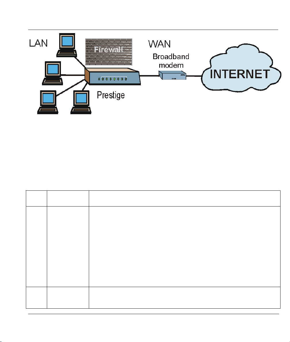
Congratulations on your purchase of the Prestige 324 Broadband Sharing Gateway with four-port switch.
Don’t forget to register your Prestige (fast, easy online registration at
www.zyxel.com) for free future product updates and information.
Your Prestige is easy to install and to configure. The embedded web configurator is a convenient platformindependent GUI (Graphical User Interface) that allows you to access the Prestige’s management settings.
All functions of the Prestige are also software configurable via the SMT (System Management Terminal)
interface. The SMT is a menu-driven interface that you can access from a terminal emulator through the
console port or through an Ethernet port using a telnet connection.
About This User's Manual
This manual is designed to guide you through the SMT configuration of your Prestige for its various
applications.
Related Documentation
Online HTML help
The online HTML help shows you how to configure each screen in the embedded web
configurator. Refer to this User’s Guide for more background information on each feature.
Supporting Disk
More detailed information and examples can be found in the included disk (as well as on the
zyxel.com web site).
Quick Start Guide
Our Quick Start Guide is designed to help you get up and running right away. It contains a
detailed easy-to-follow connection diagram, default settings, handy checklists and information on
setting up your network and configuring for Internet access.
Packing List Card
The Packing List Card lists all items that should have come in the package.
ZyXEL Glossary and Web Site
Please refer to www.zyxel.com
documentation.
Preface xxiii
for an online glossary of networking terms and additional support

Prestige 324 Intelligent Broadband Sharing Gateway
Syntax Conventions
• Mouse action sequences are denoted using a comma. For example, click Start, Settings, Control
Panel, Network means first you click Start, move the mouse pointer over Settings, then move the
mouse pointer over Control Panel and finally click Network
• “Enter” means for you to type one or more characters and press the carriage return. “Select” or
“Choose” means for you to select one from the predefined choices.
• The SMT menu titles and labels are in Bold Times New Roman font. The choices of a menu item are
in Bold Arial font. A single keystroke is in Arial font and enclosed in square brackets, for instance,
[ENTER] means the Enter, or carriage return, key; [ESC] means the escape key and [SPACE BAR]
means the space bar. [UP] and [DOWN] are the up and down arrow keys.
• For brevity’s sake, we will use “e.g.” as shorthand for “for instance” and “i.e.” for “that is” or “in other
words” throughout this manual.
• The Prestige 324 may be referred to as the Prestige or the P324 in this manual. Occasionally, SMT
screens may refer to the Prestige as a router.
xxiv Preface


Getting Started
PPaarrtt II::
Getting Started
This section helps you connect, install and setup your Prestige to operate on your network and
access the Internet.
I


Prestige 324 Intelligent Broadband Sharing Gateway
Chapter 1
Getting to Know Your Prestige
This chapter introduces the main applications of the Prestige as well as a list of key features.
1.1 Intelligent Broadband Sharing Gateway
The Prestige is a dual Ethernet Broadband Sharing Gateway with an integrated 4-port switch and robust
network management features for Internet access via external Cable/xDSL modem. A combination of
switch and router makes your Prestige a cost-effective and viable network solution. A 4-port bandwidthsensitive 10/100Mbps switch provides greater network efficiency than traditional hubs because the
bandwidth is dedicated and not shared. An unlimited number of computers may be connected to your
Prestige by adding other hubs if your LAN consists of more than 4 computers.
The Prestige web configurator is a breeze to operate and independent of the operating system you use.
1.2 Features of the Prestige 324
The following are the main hardware and firmware features of the Prestige.
1.2.1 Hardware Features
10/100MB Auto-negotiating Ethernet WAN
This auto-negotiation feature allows the Prestige to detect the speed of incoming transmissions and adjust
appropriately without manual intervention. It allows data transfer of either 10 Mbps or 100 Mbps in either
half-duplex or full-duplex mode depending on your Ethernet network.
Integrated 4-Port 10/100MB Auto-sensing Ethernet Switch
The 10/100M LAN interface enables fast data transfers of 10Mbps or 100Mbps in either half-duplex or
full-duplex mode depending on your Ethernet network. Auto-sensing allows you to use either a crossover
Ethernet cable or a straight-through Ethernet cable to connect your device to either a computer or external
hub. In other words these ports automatically adjust according to the type of cable so that either straightthrough Ethernet cable or crossover Ethernet cable may be used.
All-in-one Console and Auxiliary Port
Set the CON/AUX switch to the “CON” side when using the CON/AUX port as a regular console port for
local device configuration and management. Set this switch to the “AUX” side when using the CON/AUX
port as an auxiliary dial-up WAN connection.
Getting to Know Your Prestige 1-1

1.2.2 Firmware Features
Full Network Management
Your Prestige offers you a variety of options for network management. It supports password protected local
and remote network management via the console port or a telnet connection using SMT (System
Management Interface). Your Prestige includes an intuitive web configurator that makes setup and
configuration easy. Included with the web configurator is embedded help designed to assist you during
setup/configuration. It also supports FTP (File Transfer Protocol) server for remote management, TFTP
(Trivial FTP), SNMP (Simple Network Management Protocol) and CI (Command Interpreter) mode.
Firewall
The Prestige is a stateful inspection firewall with DoS (Denial of Service) protection. By default, when the
firewall is activated, all incoming traffic from the WAN to the LAN is blocked unless it is initiated from
the LAN. The Prestige firewall supports TCP/UDP inspection, DoS detection and prevention, real time
alerts, NETBIOS packet filtering, reports and logs.
Content Filtering
The Prestige can block web features such as ActiveX controls, Java applets and cookies, as well as disable
web proxies. The Prestige can also block specific URLs by using the keyword feature.
Packet Filtering
Packet filtering blocks unwanted traffic from entering/leaving your network.
Universal Plug and Play (UPnP)
Using the standard TCP/IP protocol, the Prestige and other UPnP enabled devices can dynamically join a
network, obtain an IP address and convey its capabilities to other devices on the network.
Traffic Redirect
Traffic Redirect is used to sustain the Internet connection. The Prestige detects if the connectivity has been
lost and will forward the outgoing traffic to another specified gateway.
NAT (Network Address Translation)
NAT (Network Address Translation - NAT, RFC 1631) allows the translation of an Internet Protocol
address used within one network to a different IP address known within another network. The Prestige can
now map multiple global IP addresses to local IP addresses of clients or servers.
Port Forwarding
Use this feature to forward incoming service requests to a server on your local network. You may enter a
single port number or a range of port numbers to be forwarded, and the local IP address of the desired
server.
1-2 Getting to Know Your Prestige

Prestige 324 Intelligent Broadband Sharing Gateway
DHCP Support
DHCP (Dynamic Host Configuration Protocol) allows the individual clients (workstations) to obtain the
TCP/IP configuration at start-up from a centralized DHCP server. The Prestige has built-in DHCP server
capability, enabled by default, which means it can assign IP addresses, an IP default gateway and DNS
servers to Windows 9x, Windows NT, Windows 2000 and other systems that support the DHCP client.
Dynamic DNS Support
With Dynamic DNS support, you can have a static hostname alias for a dynamic IP address, allowing the
host to be more easily accessible from various locations on the Internet. You must register for this service
with a Dynamic DNS service provider.
IP Multicast
Traditionally, IP packets are transmitted in two ways - unicast or broadcast. Multicast is a third way to
deliver IP packets to a group of hosts. IGMP (Internet Group Management Protocol) is the protocol used to
support multicast groups. The latest version is version 2 (see RFC 2236). The Prestige supports versions 1
and 2.
IP Alias
IP alias allows you to partition a physical network into logical networks over the same Ethernet interface.
Call Scheduling
Configure call time periods to restrict and allow access for users on remote nodes.
Call Control
The Prestige provides budget management for outgoing calls and chronicles incoming and outgoing calls.
RoadRunner Support
In addition to standard cable modem services, the Prestige supports Time Warner’s RoadRunner Service.
PPPoE Support
PPPoE facilitates the interaction of a host with a broadband modem to achieve access to high-speed data
networks via a familiar "dial-up networking" user interface.
PPTP Support
Point-to-Point Tunneling Protocol (PPTP) is a network protocol that enables secure transfer of data from a
remote client to a private server, creating a Virtual Private Network (VPN) using a TCP/IP-based network.
PPTP supports on-demand, multi-protocol and virtual private networking over public networks, such as the
Internet.
Getting to Know Your Prestige 1-3

Time and Date Setting
This feature (menu 24.10) allows you to get the current time and date from an external server when you
power up your Prestige. The real time is then displayed in the Prestige Menu 24.1- System Status and
error logs. If you do not choose a time service protocol that your timeserver will send when the Prestige
powers up you can enter the time manually but each time the system is booted, the time and date will be
reset to 1/1/2000 0:0:0.
Logging and Tracing
♦ Built-in message logging and packet tracing.
♦ Unix syslog facility support.
Embedded FTP and TFTP Services
The Prestige’s embedded FTP and TFTP services enable the fast upgrade of firmware via standard file
transfer protocols.
SNMP
SNMP (Simple Network Management Protocol) is a protocol used for exchanging management
information between network devices. SNMP is a member of the TCP/IP protocol suite. Your Prestige
supports SNMP agent functionality, which allows a manager station to manage and monitor the Prestige
through the network. The Prestige supports SNMP version one (SNMPv1).
Brute-Force Password Guessing Protection
The Prestige has a special protection mechanism to discourage brute-force password guessing attacks on
the Prestige’s management interfaces. Brute-force password guessing is repeatedly trying different
combinations of letters, numbers and so on until the password is found. Brute-Force Password Guessing
Protection enforces a wait-time after a certain number of incorrect passwords have been entered This waittime must expire before another password can be entered. Please see the appendices for details about
configuring this feature using CI commands.
1
1.3 Broadband Internet Access via Cable or DSL Modem
A cable modem or DSL modem can be connected to the Prestige WAN Ethernet port and up to four
computers can be connected to the four Prestige 10/100M LAN Ethernet ports for super-fast broadband
Internet access. The Prestige provides not only the high speed Internet access but also a complete solution
to efficiently manage data traffic on your network.
1
Not available at the time of writing.
1-4 Getting to Know Your Prestige
Prestige 324 Intelligent Broadband Sharing Gateway
Figure 1-1 Internet Access Application
1.4 Internet Access Configuration Checklist
The following table shows the minimum SMT menu configurations you’ll need to make (without changing
the default Prestige values) in order to access the Internet. See your Quick Start Guide and the embedded
web configurator online help for information on using the web configurator Internet access wizard to access
the Internet (preferred method for non-experienced SMT users).
Table 1-1 Internet Access Configuration Checklist
SMT
#
1 System Name This field is for identification purposes but because some ISPs check this name
2 MAC Address:
FIELD ACTION
you should enter your computer’s “Computer Name”.
• In Windows 95/98 click Start, Settings, Control Panel, Network. Click the
Identification tab, note the entry for the Computer Name field and enter it as
the System Name.
• In Windows 2000, click Start, Settings, Control Panel, Network
Identification. Click the Identification tab, note the entry for the Computer
Name field and enter it as the System Name.
• In Windows XP, click Start, Control Panel, System. Click the Computer
Name tab. Note the entry for the Computer Description field and enter it as the
System Name.
The default is Factory Default, which is the factory assigned default MAC
Assigned By
Address. We recommend you choose IP Address attached on LAN and enter
the IP address of the workstation on the LAN whose MAC you are cloning.
Getting to Know Your Prestige 1-5

Table 1-1 Internet Access Configuration Checklist
SMT
#
4 Encapsulation
PPTP You need to know your login name, password and connection ID/Name. The
PPPoE You need to know your login name, password and service name. The latter may
IP Address
Once these key fields have been configured, you should be able to enjoy super-fast Internet access with
your Prestige!
FIELD ACTION
Choose PPPoE if you have a dial-up connection to the Internet (or PPTP if you
reside in France or Austria); otherwise choose Ethernet. Choose from RR-
Manager, RR-Telstra or RR- Toshiba if your ISP is Time Warner's
RoadRunner; otherwise choose Standard.
latter may not be obligatory for some ISPs, but if it is you must follow the “c:id”
and “n:name” format.
not be obligatory for some ISPs.
If your ISP did not assign you a fixed IP address, select Dynamic, otherwise
Assignment
select Static and enter the IP address & subnet mask in the IP address and IP
Subnet Mask fields.
1-6 Getting to Know Your Prestige
Hardware Installation & Initial Setup
This chapter shows you how to connect hardware and perform the initial setup.
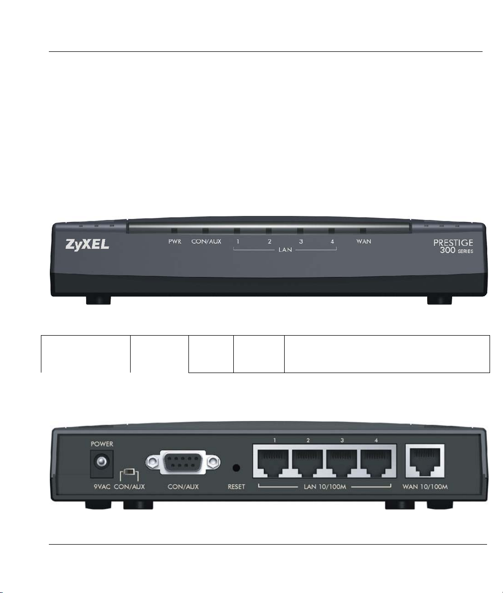
2.1 Front Panel
Prestige.
Prestige 324 Intelligent Broadband Sharing Gateway
Chapter 2
Panel
CON/AUX Console/
Auxiliary
Green On The port is in console mode (CON/AUX switch
set to CON) and is connected to a management
computer.
2.2 Prestige Rear Panel and Connections
Figure 2-1 Prestige Rear Panel Connections
Hardware Installation & Initial Setup 2-1

Table 2-1Prestige Rear Panel Connections
CONNECTION DESCRIPTION AND FUNCTION
Power 9V AC Connect the included power adaptor to the power supply and connect the other end of
the power adaptor cable to this socket.
Do this step last. Use only the included power adapter!
See the Power Adapter Specification Appendix for regional
specifications.
Power 9V AC Connect the end of the included power adaptor (use only this adapter) to this power
socket.
Use only the included power adapter! See the Power Adapter
Specification Appendix for regional specifications.
CON/AUX
switch
CON/AUX port
Set this switch to the “CON” side to use the CON/AUX port as a regular console port for
local device configuration and management. Connect the 9-pin male end of the console
cable to the console port of the Prestige and the other end (choice of 9-pin or 25-pin,
depending on your computer) end to a serial port (COM1, COM2 or other COM port) of
your computer. You can use an extension RS-232 cable if the enclosed one is too short.
Your computer should have a terminal emulation communications program (such as
HyperTerminal) set to VT100 terminal emulation, no parity, 8 data bits, 1 stop bit, no data
flow and 9600 bps port speed.
Set this switch to the “AUX” side to use the CON/AUX port as an auxiliary dial-up WAN
connection. Connect the 9-pin male end of the RS-232 Y-cable to the CON/AUX port and
use the included CON/AUX converter on the other 9-pin end of the cable to connect to a
modem or TA.
2-2 Hardware Installation & Initial Setup

Prestige 324 Intelligent Broadband Sharing Gateway
CON/AUX
switch
CON/AUX port
Reset You only need to use this button if you’ve forgotten the Prestige’s password. It returns
LAN 10/100M Connect these auto-negotiating (10/100M) auto-sensing LAN ports to local computers or
WAN 10/100M Connect your Cable/DSL modem to this port with the cable that came with your modem.
Just connect this port if you want to configure the Prestige using the SMT via console
port or set up a backup WAN connection.
Set this switch to the “CON” side to use the CON/AUX port as a regular console port for
local device configuration and management. Connect the 9-pin male end of the console
cable to the console port of the Prestige and the other end to a serial port (COM1, COM2
or other COM port) of your computer. You can use an extension RS-232 cable if the
enclosed one is too short. Your computer should have a terminal emulation
communications program (such as HyperTerminal) set to VT100 terminal emulation, no
parity, 8 data bits, 1 stop bit, no data flow and 9600 bps port speed.
Set this switch to the “AUX” side to use the CON/AUX port as an auxiliary dial-up WAN
connection. Connect the 9-pin male end of the RS-232 Y-cable to the CON/AUX port and
use the included CON/AUX converter on the other 9-pin end of the cable to connect to a
modem or TA.
the Prestige to the factory defaults (password is 1234, LAN IP address 192.168.1.1,
terminal emulation settings set to VT100 terminal emulation, no parity, 8 data bits, 1 stop
bit, no data flow and 9600 bps port speed).
to an external hub using straight-through Ethernet or crossover Ethernet cables. Autosensing means that these ports can automatically adjust to the type of Ethernet cable
you use.
If you want to connect a cable modem, you must connect the coaxial cable from your
cable service to the threaded coaxial cable connector on the back of the cable modem.
Connect an DSL modem to the DSL wall jack. The WAN connection cable should be
STP (Shielded Twisted Pair).
2.3 Turning on Your Prestige
After you’ve made the connections, connect the power cable to a power supply and look at the front panel
LEDs. The PWR LED blinks while performing system testing and then turns steady on if the testing is
successful. The CON/AUX, LAN, and WAN LEDs turn on if they are properly connected.
Hardware Installation & Initial Setup 2-3
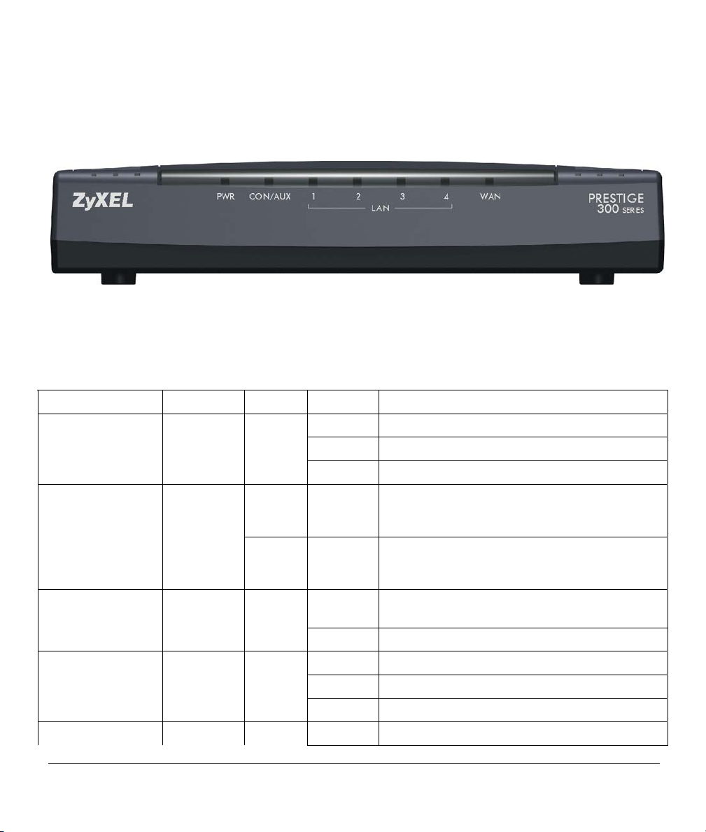
2.4 Front Panel LEDs
The LEDs on the front panel indicate the operational status of the Prestige.
Figure 2-2 Front Panel
The following table describes the LED functions.
Table 2-2 LED Descriptions
LED FUNCTION COLOR STATUS MEANING
PWR Power Green On The Prestige is receiving power.
Off The system is not ready or failed.
Flashing The system is performing system tests.
CON/AUX Console/
Auxiliary
Orange On The port is in auxiliary mode (CON/AUX switch
Orange Flashing Data is being sent/received through the backup
Off There is no connection to the CON/AUX port.
10M LAN1,2,3,4 LAN Off The 10M LAN port(s) is not connected.
Green On The Prestige is connected to a 10M LAN port(s).
Flashing The 10M LAN is sending/receiving packets.
100M LAN1,2,3,4 Off The 100M LAN port(s) is not connected.
Green On The port is in console mode (CON/AUX switch
set to CON) and is connected to a management
computer.
set to AUX), is connected to a modem or TA and
the link is up.
modem or TA.
2-4 Hardware Installation & Initial Setup

Prestige 324 Intelligent Broadband Sharing Gateway
Table 2-2 LED Descriptions
LED FUNCTION COLOR STATUS MEANING
Orange On The Prestige is connected to a 100Mbps LAN
port(s).
Flashing The 100M LAN port(s) is sending/receiving
packets.
WAN WAN Off The WAN Link is not ready, or has failed.
Green On The 10M WAN Link is ok.
Flashing The 10M WAN link is sending/receiving packets.
Orange On The 100M WAN Link is ok.
Flashing The 10oM WAN link is sending/receiving
packets.
Hardware Installation & Initial Setup 2-5

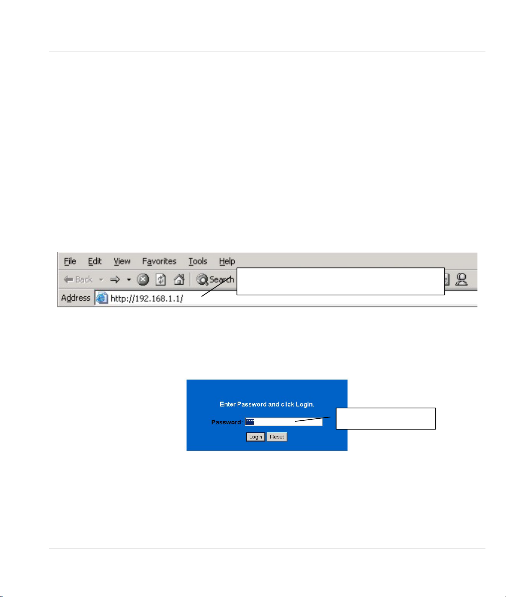
Prestige 324 Intelligent Broadband Sharing Gateway
Chapter 3
Introducing the Web Configurator
This chapter describes how to access the Prestige web configurator.
3.1 Accessing the Prestige Web Configurator
Step 1. Make sure your Prestige hardware is properly connected (refer to instructions in the
hardware installation chapter).
Step 2. Prepare your computer/computer network to connect to the Internet (refer to the Quick Start
Guide or the appendices in this guide).
Step 3. Launch your web browser. Enter “192.168.1.1” as the web site address.
Web site address.
Figure 3-1 Web Site Address
Step 1. The default password (“1234”) is already in the password field (in non-readable format). Click
Login to proceed to a screen asking you to change your password. Click Reset to revert to the
default password in the password field.
Default password.
Figure 3-2 Default Password
Step 2. It is highly recommended you change the default password! Enter a new password, retype it to
confirm and click Apply; alternatively click Ignore to proceed to the main menu if you do not
want to change the password now.
WAN Setup 3-1Introducing the Web Configurator

Change default password.
Figure 3-3 Change Password
Step 3. You should now see the web configurator MAIN MENU screen.
Click WIZARD to begin a series of screens to help you configure your Prestige for the first time.
Click a link under SETUP in the navigation panel to configure advanced Prestige features.
Click MAINTENANCE in the navigation panel to see Prestige performance statistics, upload
firmware and back up, restore or upload a configuration file.
Click LOGOUT when you have finished a Prestige management session. The Prestige web
configurator automatically logs you out if it is left idle for five minutes. This idle timeout timer is
one of the many Prestige features that you may edit using the web configurator.
3-2 Introducing the Web Configurator

LOGOUT
Prestige 324 Intelligent Broadband Sharing Gateway
WIZARD
Navigation panel
Figure 3-4 The MAIN MENU Screen of the Web Configurator
Follow the instructions you see in the MAIN MENU screen or click the
icon
(located in the top right corner of most screens) to view embedded help.
The
icon does not appear in the MAIN MENU screen.
If you forget your password, refer to section 5.3.1 to reset the default configuration file.
WAN Setup 3-3Introducing the Web Configurator


Prestige 324 Intelligent Broadband Sharing Gateway
Chapter 4
Wizard Setup
This chapter shows you how to use the Wizard to access the Internet for the first time.
4.1 Introduction to Wizard Screens
The Wizard consists of screens to help you configure your device to access the Internet. The second screen
has three variations depending on what encapsulation type you use. Refer to your ISP checklist in the Quick
Start Guide to know what to enter in each field. Leave a field blank if you don’t have that information.
4.1.1 General Setup and System Name
General Setup contains administrative and system-related information. System Name is for identification
purposes. However, because some ISPs check this name you should enter your computer's "Computer
Name".
• In Windows 95/98 click Start, Settings, Control Panel, Network. Click the Identification tab, note
the entry for the Computer Name field and enter it as the System Name.
• In Windows 2000, click Start, Settings, Control Panel and then double-click System. Click the
Network Identification tab and then the Properties button. Note the entry for the Computer name
field and enter it as the System Name.
• In Windows XP, click Start, My Computer, View system information and then click the Computer
Name tab. Note the entry in the Full computer name field and enter it as the Prestige System Name.
4.1.2 Domain Name
The Domain Name entry is what is propagated to the DHCP clients on the LAN. If you leave this blank,
the domain name obtained by DHCP from the ISP is used. While you must enter the host name (System
Name) on each individual computer, the domain name can be assigned from the Prestige via DHCP.
LAN Setup 4-1Wizard Setup

Click Next to configure the Prestige for internet access.
Figure 4-1 Wizard 1
4.2 Wizard Setup: Screen 2
The Prestige offers three choices of encapsulation. They are Ethernet, PPTP or PPPoE.
4.2.1 Ethernet
Choose Ethernet when the WAN port is used as a regular Ethernet.
4-2 Wizard Setup

Prestige 324 Intelligent Broadband Sharing Gateway
Table 4-1 Wizard 2: Ethernet Encapsulation
Table 4-2 Ethernet Encapsulation
FIELD DESCRIPTION
ISP Parameters for Internet Access
Encapsulation
Service Type
To continue, click Next. To return to the previous screen, click Back.
You must choose the Ethernet option when the WAN port is used as a regular
Ethernet. Otherwise, choose PPPoE or PPTP for a dial-up connection.
Choose from Standard or a RoadRunner version. The User Name, Password
and Login Server IP Address fields are not applicable (N/A) for the latter.
4.2.2 PPTP Encapsulation
Point-to-Point Tunneling Protocol (PPTP) is a network protocol that enables transfer of data from a remote
client to a private server, creating a Virtual Private Network (VPN) using TCP/IP-based networks.
LAN Setup 4-3Wizard Setup

PPTP supports on-demand, multi-protocol, and virtual private networking over public networks, such as the
Internet.
For more information on PPTP, please refer to the appendices
The Prestige supports one PPTP server connection at any given time.
Figure 4-2 Wizard 2: PPTP Encapsulation
Table 4-3 PPTP Encapsulation
FIELD DESCRIPTION
ISP Parameters for Internet Access
4-4 Wizard Setup

Prestige 324 Intelligent Broadband Sharing Gateway
Table 4-3 PPTP Encapsulation
FIELD DESCRIPTION
Encapsulation
User Name Type the user name given to you by your ISP.
Password Type the password associated with the User Name above.
Nailed Up
Connection
Idle Timeout
PPTP Configuration
My IP Address Type the (static) IP address assigned to you by your ISP.
My IP Subnet Mask Type the subnet mask assigned to you by your ISP (if given).
Server IP Address Type the IP address of the PPTP server.
Connection
ID/Name
To continue, click Next. To return to the previous screen, click Back.
Select PPTP from the pull-down list box.
Select Nailed Up Connection if you do not want the connection to time out.
Type the time in seconds that elapses before the router automatically disconnects
from the PPTP server. The default is 45 seconds.
Enter the connection ID or connection name in this field. It must follow the "c:id" and
"n:name" format. For example, C:12 or N:My ISP.
This field is optional and depends on the requirements of your xDSL modem.
4.2.3 PPPoE Encapsulation
Point-to-Point Protocol over Ethernet (PPPoE) functions as a dial-up connection. PPPoE is an IETF
(Internet Engineering Task Force) draft standard specifying how a host personal computer interacts with a
broadband modem (for example xDSL, cable, wireless, etc.) to achieve access to high-speed data networks.
It preserves the existing Microsoft Dial-Up Networking experience and requires no new learning or
procedures.
For the service provider, PPPoE offers an access and authentication method that works with existing access
control systems (for instance, Radius). For the user, PPPoE provides a login and authentication method that
LAN Setup 4-5Wizard Setup
the existing Microsoft Dial-Up Networking software can activate, and therefore requires no new learning or
procedures for Windows users.
One of the benefits of PPPoE is the ability to let end users access one of multiple network services, a
function known as dynamic service selection. This enables the service provider to easily create and offer
new IP services for specific users.
Operationally, PPPoE saves significant effort for both the end user and ISP/carrier, as it requires no specific
configuration of the broadband modem at the customer site.
By implementing PPPoE directly on the Prestige (rather than individual computers), the computers on the
LAN do not need PPPoE software installed, since the Prestige does that part of the task. Furthermore, with
NAT, all of the LAN's computers will have access.
For more information on PPPoE, please refer Appendix A.
Figure 4-3 Wizard2: PPPoE Encapsulation
4-6 Wizard Setup

Prestige 324 Intelligent Broadband Sharing Gateway
Table 4-4 PPPoE Encapsulation
FIELD DESCRIPTION
ISP Parameter for Internet Access
Encapsulation
Service Name
(Optional)
User Name Type the user name given to you by your ISP.
Password Type the password associated with the user name above.
Nailed Up
Connection
Idle Timeout
To continue, click Next.
To return to the previous screen, click Back.
Choose an encapsulation method from the pull-down list box. PPPoE forms a dial-up
connection.
Type the name of your service provider.
Select Nailed Up Connection if you do not want the connection to time out.
Type the time in seconds that elapses before the router automatically disconnects from
the PPPoE server. The default time is 100 seconds.
4.3 Wizard Setup: Screen 3
4.3.1 WAN IP Address Assignment
Every computer on the Internet must have a unique IP address. If your networks are isolated from the
Internet, for instance, only between your two branch offices, you can assign any IP addresses to the hosts
without problems. However, the Internet Assigned Numbers Authority (IANA) has reserved the following
three blocks of IP addresses specifically for private networks.
LAN Setup 4-7Wizard Setup

Table 4-5 Private IP Address Ranges
10.0.0.0 - 10.255.255.255
172.16.0.0 - 172.31.255.255
192.168.0.0 - 192.168.255.255
You can obtain your IP address from the IANA, from an ISP or have it assigned by a private network. If
you belong to a small organization and your Internet access is through an ISP, the ISP can provide you with
the Internet addresses for your local networks. On the other hand, if you are part of a much larger
organization, you should consult your network administrator for the appropriate IP addresses.
Regardless of your particular situation, do not create an arbitrary IP address;
always follow the guidelines above. For more information on address
assignment, please refer to RFC 1597, Address Allocation for Private Internets
and RFC 1466, Guidelines for Management of IP Address Space.
4.3.2 IP Address and Subnet Mask
Similar to the way houses on a street share a common street name, so too do computers on a LAN share
one common network number.
Where you obtain your network number depends on your particular situation. If the ISP or your network
administrator assigns you a block of registered IP addresses, follow their instructions in selecting the IP
addresses and the subnet mask.
If the ISP did not explicitly give you an IP network number, then most likely you have a single user
account and the ISP will assign you a dynamic IP address when the connection is established. If this is the
case, it is recommended that you select a network number from 192.168.0.0 to 192.168.255.0 and you must
enable the Network Address Translation (NAT) feature of the Prestige. The Internet Assigned Number
Authority (IANA) reserved this block of addresses specifically for private use; please do not use any other
number unless you are told otherwise. Let's say you select 192.168.1.0 as the network number; which
covers 254 individual addresses, from 192.168.1.1 to 192.168.1.254 (zero and 255 are reserved). In other
words, the first three numbers specify the network number while the last number identifies an individual
workstation on that network.
4-8 Wizard Setup

Prestige 324 Intelligent Broadband Sharing Gateway
Once you have decided on the network number, pick an IP address that is easy to remember, for instance,
192.168.1.1, for your Prestige, but make sure that no other device on your network is using that IP.
The subnet mask specifies the network number portion of an IP address. Your Prestige will compute the
subnet mask automatically based on the IP address that you entered. You don't need to change the subnet
mask computed by the Prestige unless you are instructed to do otherwise.
4.3.3 DNS Server Address Assignment
Use DNS (Domain Name System) to map a domain name to its corresponding IP address and vice versa,
for instance, the IP address of www.zyxel.com is 204.217.0.2. The DNS server is extremely important
because without it, you must know the IP address of a computer before you can access it.
There are two ways that an ISP disseminates the DNS server addresses.
1. The ISP tells you the DNS server addresses, usually in the form of an information sheet, when you sign
up. If your ISP gives you DNS server addresses, enter them in the DNS Server fields in DHCP Setup.
2. Leave the DNS Server fields in DHCP Setup blank (for example 0.0.0.0). The Prestige acts as a DNS
proxy when this field is blank.
4.3.4 WAN MAC Address
You can configure the WAN port's MAC Address by either using the factory default or cloning the MAC
address from a workstation on your LAN. Once it is successfully configured, the address will be copied to
the "rom" file (ZyNOS configuration file). It will not change unless you change the setting or upload a
different "rom" file.
ZyXEL recommends you clone the MAC address from a workstation on your LAN
even if your ISP does not require MAC address authentication.
Your Prestige WAN Port is always set at half-duplex mode as most cable/DSL modems only support half-
duplex mode. Make sure your modem is in half-duplex mode. Your Prestige supports full duplex mode on
the LAN side.
LAN Setup 4-9Wizard Setup
Table 4-6 Example of Network Properties for LAN Servers with Fixed IP Addresses
Choose an IP address 192.168.1.2-192.168.1.32; 192.168.1.65-192.168.1.254.
Subnet mask 255.255.255.0
Gateway (or default route) 192.168.1.1(Prestige LAN IP)
Figure 4-4 Wizard 3
Table 4-7 WAN Setup
FIELD DESCRIPTION
WAN IP Address Assignment
Get automatically from
ISP
Use fixed IP address Select this option If the ISP assigned a fixed IP address.
Select this option If your ISP did not assign you a fixed IP address. This is the
default selection.
4-10 Wizard Setup

Prestige 324 Intelligent Broadband Sharing Gateway
Table 4-7 WAN Setup
FIELD DESCRIPTION
IP Address
IP Subnet Mask
Gateway IP Address
DNS Server Address Assignment
Get automatically from
ISP
Use fixed IP address DNS Server IP Address
Primary/Secondary DNS
Server
WAN MAC Address
Factory Default Select this option to use the factory assigned default MAC Address.
Spoof this Computer's
MAC address - IP
Address
Enter your WAN IP address in this field when you selected Use Fixed IP
Address.
Enter the IP subnet mask in this field if applicable when you selected Use
Fixed IP Address. This field is not visible when you chose PPPoE
encapsulation in the previous wizard screen.
Enter the gateway IP address in this field if applicable when you selected Use
Fixed IP Address. This field is not visible when you chose PPPoE
encapsulation in the previous wizard screen.
Select this option if your ISP does not give you DNS server addresses. This
option is selected by default.
Select this option If your ISP provides you a DNS server address.
If you selected the Use fixed IP address – Primary/Secondary DNS Server
option, enter the provided DNS addresses in these fields.
The MAC address field allows users to configure the WAN port's MAC Address
by either using the factory default or cloning the MAC address from a
workstation on your LAN.
Select this option and enter the IP address of the workstation on the LAN
whose MAC you are cloning. Once it is successfully configured, the address will
be copied to the rom file (ZyNOS configuration file). It will not change unless
you change the setting or upload a different rom file. It is advisable to clone the
MAC address from a workstation on your LAN even if your ISP does not
presently require MAC address authentication.
To return to the previous screen, click Back.
To save and complete the wizard setup, click Finish.
LAN Setup 4-11Wizard Setup

4.4 Basic Setup Complete
Well done! You have successfully set up your Prestige to operate on your network and access the Internet.
The rest of this User’s Guide shows you how to configure the SMT menus except where no SMT menus
exist for certain features such as UPnP and the firewall. For web configurator screens that have SMT menu
equivalents, read this guide for background information, but refer to the web screen online help for actual
screen configuration.
4-12 Wizard Setup

Prestige 324 Intelligent Broadband Sharing Gateway
Chapter 5
Introducing the SMT and General Setup
This chapter shows you how to access the SMT menus via the console port, how to navigate the
SMT and how to configure SMT menu 1.
5.1 Accessing the Prestige via the Console Port
Make sure you have the physical connection properly set up as described in the hardware installation
chapter.
In addition to the contents of your package, there are other hardware and software requirements you need
before you can install and use your Prestige. These requirements include:
1. A computer(s) with an installed Ethernet NIC (Network Interface Card).
2. A computer equipped with terminal emulation communications software configured to the
following parameters:
♦ VT100 terminal emulation.
♦ 9600 baud.
♦ No parity, 8 data bits, 1 stop bit, flow control set to none.
3. A cable/DSL modem and an ISP account.
5.1.1 Initial Screen
When you turn on your Prestige, it performs several internal tests as well as line initialization.
After the tests, the Prestige asks you to press [ENTER] to continue, as shown next.
Introducing the SMT and General Setup 5-1

Prestige 324 Intelligent Broadband Sharing Gateway
Copyright (c) 1994 - 2002 ZyXEL Communications Corp.
initialize ch =0, ethernet address: 00:a0:c5:01:23:45
initialize ch =1, ethernet address: 00:a0:c5:01:23:46
Press ENTER to continue...
Figure 5-1 Initial Screen
5.1.2 Entering the Password
The login screen appears after you press [ENTER], prompting you to enter the password, as shown next.
For your first login, enter the default password 1234. As you type the password, the screen displays an (X)
for each character you type.
Note that if there is no activity for longer than five minutes after you log in, your Prestige will
automatically log you out and will display a blank screen. If you see a blank screen, press [ENTER] to
bring up the login screen again.
Enter Password : XXXX
Figure 5-2 Password Screen
5.2 Navigating the SMT Interface
The SMT (System Management Terminal) is the interface that you use to configure your Prestige.
Several operations that you should be familiar with before you attempt to modify the configuration are
listed next.
5-2 Introducing the SMT and General Setup

Prestige 324 Intelligent Broadband Sharing Gateway
Table 5-1 Main Menu Commands
OPERATION DESCRIPTION
Move down to
another menu
Move up to a
previous menu
Move to a “hidden”
menu
Move the cursor Within a menu, press [ENTER] to move to the next field. You can also use the
Entering information You need to fill in two types of fields. The first requires you to type in the appropriate
Required fields All fields with the symbol <?> or ChangeMe must be filled in order be able to save
N/A fields Some of the fields in the SMT will show a <N/A>. This symbol refers to an option
Save your
configuration
Exit the SMT Type 99 at the main menu prompt and press [ENTER] to exit the SMT interface.
To move forward to a submenu, type in the number of the desired submenu and
press [ENTER].
Press the [ESC] key to move back to the previous menu.
Fields beginning with “Edit” lead to hidden menus and have a default setting of No.
Press [SPACE BAR] to change No to Yes, and then press [ENTER] to go to a
“hidden” menu.
[UP]/[DOWN] arrow keys to move to the previous and the next field, respectively.
information. The second allows you to cycle through the available choices by
pressing [SPACE BAR] and then [ENTER].
the new configuration.
that is Not Applicable.
Save your configuration by pressing [ENTER] at the message “Press ENTER to
confirm or ESC to cancel”. Saving the data on the screen will take you, in most
cases to the previous menu.
5.2.1 Main Menu
After you enter the password, the SMT displays the Prestige Main Menu, as shown next.
Introducing the SMT and General Setup 5-3

Prestige 324 Intelligent Broadband Sharing Gateway
Copyright (c) 1994 - 2002 ZyXEL Communications Corp.
Getting Started Advanced Management
1. General Setup
2. WAN Setup
3. LAN Setup
4. Internet Access Setup
Advanced Applications
11. Remote Node Setup
12. Static Routing Setup
15. NAT Setup
Enter Menu Selection Number:
Prestige 324 Main Menu
21. Filter and Firewall Setup
22. SNMP Configuration
23. System Password
24. System Maintenance
26. Schedule Setup
99. Exit
Figure 5-3 Prestige Main Menu
5.2.2 System Management Terminal Interface Summary
Table 5-2 Main Menu Summary
NO. Menu Title FUNCTION
1 General Setup Use this menu to set up routing/bridging and general information.
2 WAN Setup Use this menu to clone a MAC address from a computer on your LAN.
3 LAN Setup Use this menu to configure LAN DHCP and TCP/IP settings as well as
apply LAN filters.
4 Internet Access Setup Configure your Internet Access setup (Internet address, gateway, login,
etc.) with this menu.
11 Remote Node Setup Use this menu to configure detailed remote node settings (your ISP is
also a remote node) as well as apply WAN filters.
12 Static Routing Setup Configure static routes for bridging and IP in this menu.
15 NAT Setup Use this menu to configure network address translation.
21 Filter and Firewall Setup Use these menus to activate the firewall and configure packet filters.
22 SNMP Configuration Use this menu to configure SNMP-related parameters.
23 System Password Change your password in this menu (recommended).
5-4 Introducing the SMT and General Setup

Prestige 324 Intelligent Broadband Sharing Gateway
Table 5-2 Main Menu Summary
NO. Menu Title FUNCTION
24 System Maintenance From displaying system status to uploading firmware, this menu provides
comprehensive system maintenance.
26 Schedule Setup Use this menu to schedule outgoing calls.
99 Exit Use this menu to exit (necessary for remote configuration).
5.3 Changing the System Password
The first thing you should do is change the default system password by following the steps shown next.
Step 1. Enter 23 in the main menu to open Menu 23 - System Password as shown next.
Menu 23 - System Password
Old Password= ?
New Password= ?
Retype to confirm= ?
Enter here to CONFIRM or ESC to CANCEL:
Figure 5-4 Menu 23 — System Security
Step 2. Enter your existing password and press [ENTER].
Step 3. Enter your new system password and press [ENTER].
Step 4. Re-type your new system password for confirmation and press [ENTER].
Note that as you type a password, the screen displays a (X) for each character you type.
Introducing the SMT and General Setup 5-5

Prestige 324 Intelligent Broadband Sharing Gateway
p
5.3.1 Resetting the Prestige
If you forget your password or cannot access the SMT menu, you will need to reload the factory-default
configuration file or use the RESET button the back of the Prestige. Uploading this configuration file
replaces the current configuration file with the factory-default configuration file. This means that you will
lose all configurations that you had previously and the speed of the console port will be reset to the default
of 9600bps with 8 data bit, no parity, one stop bit and flow control set to none. The password will be reset
to “1234”, also.
Uploading a Configuration File Via Console Port
Turn off the Prestige, begin a terminal emulation software session and turn on the Prestige again. When you
see the message "Press Any key to enter Debug Mode within 3 seconds", press any key to enter debug
mode.
Step 1. Enter "y" at the prompt below to go into debug mode.
Step 2. Enter "atlc" after "Enter Debug Mode" message.
Step 3. Wait for "Starting XMODEM upload" message before activating Xmodem upload on your
terminal. This is an example Xmodem configuration upload using HyperTerminal. You should
already have downloaded the correct file from your nearest ZyXEL FTP site.
Step 4. Click Transfer, then Send File to display the following screen.
Type the configuration file’s
location, or click Browse to
search for it.
Choose the Xmodem
rotocol.
Then click Send.
Figure 5-5 Example Xmodem Upload
Step 5. After successful firmware upload, enter "atgo" to restart the router.
5-6 Introducing the SMT and General Setup

Prestige 324 Intelligent Broadband Sharing Gateway
Procedure To Use The RESET Button
Make sure the PWR led is on (not blinking) when you begin this procedure.
Step 1. Press the RESET button for ten seconds, then release it. If the PWR LED begins to blink,
the defaults have been restored and the Prestige restarts. Otherwise, go to step 2.
Step 2. Turn the Prestige off.
Step 3. While pressing the RESET button, turn the Prestige on.
Step 4. Continue to hold the RESET button. The PWR LED will begin to blink and flicker very
quickly after about 10 or 15 seconds. This indicates that the defaults have been restored and
the Prestige is now restarting.
5.4 General Setup
Menu 1 - General Setup contains administrative and system-related information (shown next). System
Name is for identification purposes. However, because some ISPs check this name you should enter your
computer’s “Computer Name”.
In Windows 95/98 click Start, Settings, Control Panel, Network. Click the Identification tab,
note the entry for the Computer Name field and enter it as the System Name.
In Windows 2000, click Start, Settings, Control Panel and then double-click System. Click the
Network Identification tab and then the Properties button. Note the entry for the Computer
name field and enter it as the System Name.
In Windows XP, click Start, Control Panel, System. Click the Computer Name tab. Note the
entry for the Computer Description field and enter this entry as the System Name.
The Domain Name entry is what is propagated to the DHCP clients on the LAN. If you leave this blank,
the domain name obtained by DHCP from the ISP is used. While you must enter the host name (System
Name) on each individual computer, the domain name can be assigned from the Prestige via DHCP.
Introducing the SMT and General Setup 5-7

Prestige 324 Intelligent Broadband Sharing Gateway
5.4.1 Dynamic DNS
Dynamic DNS (Domain Name System) allows you to update your current dynamic IP address with one or
many dynamic DNS services so that anyone can contact you (in NetMeeting, CU-SeeMe or other services).
You can also access your FTP server or Web site on your own computer using a DNS-like address (for
example, myhost.dhs.org, where myhost is a name of your choice) which will never change instead of using
an IP address that changes each time you reconnect. Your friends or relatives will always be able to call
you even if they don’t know your IP address.
First of all, you need to have registered a dynamic DNS account with www.dyndns.org. This is for people
with a dynamic IP from their ISP or DHCP server that would still like to have a DNS name.
To use this service, you must register with the Dynamic DNS service provider. The Dynamic DNS service
provider will give you a password or key. The Prestige supports www.dyndns.org. You can apply to this
service provider for Dynamic DNS service.
DYNDNS Wildcard
Enabling the wildcard feature for your host causes *.yourhost.dyndns.org to be aliased to the same IP
address as yourhost.dyndns.org. This feature is useful if you want to be able to use, for example,
www.yourhost.dyndns.org and still reach your hostname.
5.4.2 Procedure For Configuring Menu 1
Step 1. Enter 1 in the main menu to open Menu 1 – General Setup (shown next).
Step 2. Fill in the required fields. Refer to the table shown next for more information about these fields.
Menu 1 - General Setup
System Name= ?
Domain Name=
Edit Dynamic DNS= No
Press ENTER to Confirm or ESC to Cancel:
Figure 5-6 Menu 1 — General Setup
5-8 Introducing the SMT and General Setup

Prestige 324 Intelligent Broadband Sharing Gateway
Table 5-3 General Setup Menu Field
FIELD DESCRIPTION EXAMPLE
System Name Choose a descriptive name for identification purposes. It is
recommended you enter your computer’s “Computer name” in this
field. This name can be up to 30 alphanumeric characters long. Spaces
are not allowed, but dashes “-” and underscores "_" are accepted.
Domain Name Enter the domain name (if you know it) here. If you leave this field
blank, the ISP may assign a domain name via DHCP. You can go to
menu 24.8 and type "sys domainname" to see the current domain
name used by your gateway.
If you want to clear this field just press the [SPACE BAR]. The domain
name entered by you is given priority over the ISP assigned domain
name.
Edit Dynamic
DNS
When you have completed this menu, press [ENTER] at the prompt “Press ENTER to Confirm…” to
save your configuration, or press [ESC] at any time to cancel.
Press the [SPACE BAR] to select Yes or No (default). Select Yes to
configure Menu 1.1 – Configure Dynamic DNS (discussed next).
P324_PLUS
zyxel.com.tw
No
5.4.3 Configuring Dynamic DNS
To configure Dynamic DNS, go to Menu 1 – General Setup and press select Yes in the Edit Dynamic
DNS field. Press [ENTER] to display Menu 1.1– Configure Dynamic DNS as shown next.
Introducing the SMT and General Setup 5-9

Prestige 324 Intelligent Broadband Sharing Gateway
Service Provider= WWW.DynDNS.ORG
Active= Yes
DDNSType= DynamicDNS
Host1=
Host2=
Host3=
EMAIL=
USER=
Password= ********
Enable Wildcard= No
Offline= N/A
Edit Update IP Address:
Use Server Detected IP= Yes
User Specified IP Addr=No
IP Addr=N/A
Press ENTER to confirm or ESC to cancel:
Menu 1.1 - Configure Dynamic DNS
Figure 5-7 Configure Dynamic DNS
Follow the instructions in the next table to configure Dynamic DNS parameters.
Table 5-4 Configure Dynamic DNS Menu Fields
FIELD DESCRIPTION EXAMPLE
Service Provider This is the name of your Dynamic DNS service provider. WWW.DynDNS.ORG
(default)
Active
Press [SPACE BAR] to select Yes and then press [ENTER] to
make dynamic DNS active.
DDNS Type
Press [SPACE BAR] and then [ENTER] to select DynamicDNS
if you have a dynamic IP address(es). Select StaticDNS if you
have a static IP address(s).
Select CustomDNS to have dyns.org provide DNS service for a
domain name that you already have from a source other than
dyndns.org.
Host1-3 Enter your host name(s) in the fields provided. You can specify
up to two host names separated by a comma in each field.
EMAIL Enter your e-mail address. mail@mailserver
USER Enter your user name.
Password Enter the password assigned to you.
Yes
DynamicDNS
(default)
me.dyndns.org
5-10 Introducing the SMT and General Setup

Prestige 324 Intelligent Broadband Sharing Gateway
Table 5-4 Configure Dynamic DNS Menu Fields
FIELD DESCRIPTION EXAMPLE
Enable Wildcard Your Prestige supports DYNDNS Wildcard. Press [SPACE BAR]
and then [ENTER] to select Yes or No This field is N/A when
you choose DDNS client as your service provider.
Offline
Edit Update IP Address:
You can select Yes in either the Use Server Detected IP field (recommended) or the User Specified IP
Addr field, but not both.
With the Use Server Detected IP and User Specified IP Addr fields both set to No, the DDNS server
automatically updates the IP address of the host name(s) with the Prestige’s WAN IP address.
DDNS does not work with a private IP address. When both fields are set to No, the Prestige must have a
public WAN IP address in order for DDNS to work.
Use Server
Detected IP
User Specified IP
Addr
IP Addr
When you have completed this menu, press [ENTER] at the prompt “Press ENTER to Confirm…” to save
your configuration, or press [ESC] at any time to cancel.
This field is only available when CustomDNS is selected in the
DDNS Type field. Press [SPACE BAR] and then [ENTER] to
select Yes. When Yes is selected,
is redirected to a URL that you have previously specified (see
www.dyndns.org
Press [SPACE BAR] to select Yes and then press [ENTER] to
have the DDNS server automatically update the IP address of
the host name(s) with the public IP address that the Prestige
uses or is behind.
You can set this field to Yes whether the IP address is public or
private, static or dynamic.
Press [SPACE BAR] to select Yes and then press [ENTER] to
update the IP address of the host name(s) to the IP address
specified below.
Only select Yes if the Prestige uses or is behind a static public
IP address.
Enter the static public IP address if you select Yes in the User
Specified IP Addr field.
for details).
http://www.dyndns.org/traffic
No
Yes
Yes
No
N/A
The IP address will be updated when you reconfigure menu 1 or perform DHCP client renewal. If you have
a private WAN IP address, then you cannot use Dynamic DNS.
Introducing the SMT and General Setup 5-11

Prestige 324 Intelligent Broadband Sharing Gateway
Chapter 6
WAN Setup and Dial Backup
This chapter describes how to configure the WAN using menu 2 and dial-backup using menus 2,
2.1 and 11.1.
6.1 Cloning The MAC Address
The MAC address field allows users to configure the WAN port's MAC address by using either the factory
default or cloning the MAC address from a computer on your LAN. Once it is successfully configured, the
address will be copied to the rom file (ZyNOS configuration file). It will not change unless you change the
setting in menu 2 or upload a different rom file.
ZyXEL recommends that you clone the MAC address of a computer on your LAN
even if your ISP does not require MAC address authentication.
MAC Address:
Assigned By= Factory default
IP Address= N/A
Dial-Backup:
Active= No
Phone Number=
Port Speed= 115200
AT Command String:
Init= at&fs0=0
Edit Advanced Setup= No
Press ENTER to Confirm or ESC to Cancel:
Press Space Bar to Toggle.
Menu 2 - WAN Setup
Figure 6-1 MAC Address Cloning in WAN Setup Menu
WAN Setup and Dial Backup 6-1

Prestige 324 Intelligent Broadband Sharing Gateway
Table 6-1 MAC Address Cloning in WAN Setup Menu
FIELD DESCRIPTION EXAMPLE
MAC Address:
Assigned By Press [SPACE BAR] and then [ENTER] to choose one of two methods
to assign a MAC Address. Choose Factory Default to select the factory
assigned default MAC Address. Choose IP address attached on LAN
to use the MAC Address of that workstation whose IP you give in the
following field.
IP Address
When you have completed this menu, press [ENTER] at the prompt “Press ENTER to Confirm…” to save
your configuration, or press [ESC] at any time to cancel.
This field is applicable only if you choose the IP address attached on
LAN method in the Assigned By field. Enter the IP address of the
computer on the LAN whose MAC you are cloning.
IP address
attached on
LAN
192.168.1.35
6.2 Dial Backup
The AUX/CON port can be used in reserve, as a traditional dial-up connection should the broadband
connection from the WAN port fail. To set up the auxiliary port (Dial Backup) for use in the event that the
regular WAN connection is dropped, first make sure you have set up the CON/AUX switch and port
connection (see the Hardware Installation chapter), then configure:
Menu 2 - WAN Setup,
Menu 2.1 - Advanced WAN Setup and
Menu 11.1 - Remote Node Profile (Backup ISP) as shown next.
Refer also to the traffic redirect section in this User’s Guide for information on an alternate backup WAN
connection.
6.2.1 Configuring Dial Backup in Menu 2
6-2 WAN Setup and Dial Backup
Prestige 324 Intelligent Broadband Sharing Gateway
MAC Address:
Assigned By= Factory default
IP Address= N/A
Dial-Backup:
Active= No
Phone Number=
Port Speed= 115200
AT Command String:
Init= at&fs0=0
Edit Advanced Setup= No
Press ENTER to Confirm or ESC to Cancel:
Menu 2 - WAN Setup
Figure 6-2 Configuring Dial Backup in Menu 2
The following table contains instructions on how to configure your WAN setup.
Table 6-2 Configuring Dial Backup in Menu 2
FIELD DESCRIPTION EXAMPLE
Dial-Backup:
Active
Phone
Number
Use this field to turn the dial-backup feature on (Yes) or off (No). No
Enter the telephone number assigned to your line by your telephone
company. This field only accepts digits; do not include dashes and
spaces.
Port Speed
Press [SPACE BAR] and then press [ENTER] to select the speed of the
connection between the Dial Backup port and the external device.
1234567
115200
Available speeds are:
9600, 19200, 38400, 57600, 115200 or 230400 bps.
AT Command
String:
Init Enter the AT command string to initialize the WAN device. Consult the
manual of your WAN device connected to your Dial Backup port for
specific AT commands.
at&fs0=0
WAN Setup and Dial Backup 6-3

Prestige 324 Intelligent Broadband Sharing Gateway
Table 6-2 Configuring Dial Backup in Menu 2
FIELD DESCRIPTION EXAMPLE
Edit Advanced
Setup
When you have completed this menu, press [ENTER] at the prompt “Press ENTER to Confirm…” to save
your configuration, or press [ESC] at any time to cancel.
To edit the advanced setup for the Dial Backup port, move the cursor to
this field; press the [SPACE BAR] to select Yes and then press
[ENTER] to go to Menu 2.1: Advanced Setup.
Yes
6.2.2 Configuring Dial Backup Using Advanced WAN Setup
Consult the manual of your WAN device connected to your Dial Backup port for
specific AT commands.
6.2.3 AT Command Strings
For regular telephone lines, the default “Dial” string tells the modem that the line uses tone dialing.
“ATDT” is the command for a switch that requires tone dialing. If your switch requires pulse dialing,
change the string to “ATDP”.
For ISDN lines, there are many more protocols and operational modes. Please consult the documentation of
your TA. You may need additional commands in both “Dial” and “Init” strings.
6.2.4 DTR Signal
The majority of WAN devices default to hanging up the current call when the DTR (Data Terminal Ready)
signal is dropped by the DTE. When “Drop DTR When Hang Up” is set to Yes, the Prestige uses this
hardware signal to force the WAN device to hang up, in addition to issuing the drop command “ATH”.
6.2.5 Response Strings
The response strings tell the Prestige the tags, or labels, immediately preceding the various call parameters
sent from the WAN device. The response strings have not been standardized; please consult the
documentation of your WAN device to find the correct tags.
6-4 WAN Setup and Dial Backup

Prestige 324 Intelligent Broadband Sharing Gateway
To edit the advanced setup for the Dial Backup port, move the cursor to the Edit Advanced Setup field in
Menu 2 - WAN Setup, press the [SPACE BAR] to select Yes and then press [ENTER].
AT Command Strings: Call Control:
Dial= atdt Dial Timeout(sec)= 60
Drop= ~~+++~~ath Retry Count= 0
Answer= ata Retry Interval(sec)= N/A
Drop Timeout(sec)= 20
Drop DTR When Hang Up= Yes Call Back Delay(sec)= 15
AT Response Strings:
CLID= NMBR =
Called Id=
Speed= CONNECT
Press ENTER to Confirm or ESC to Cancel:
Menu 2.1 - Advanced WAN Setup
Figure 6-3 Menu 2.1 Advanced WAN Setup
The following table describes fields in this menu.
Table 6-3 Advanced WAN Port Setup: AT Commands Fields
FIELD DESCRIPTION DEFAULT
AT Command
Strings:
Dial Enter the AT Command string to make a call. atdt
Drop Enter the AT Command string to drop a call. “~” represents a one
+++ath
second wait, e.g., “~~~+++~~ath” can be used if your modem has a
slow response time.
Answer Enter the AT Command string to answer a call. ata
Drop DTR When
Hang Up
Press the [SPACE BAR] to choose either Yes or No. When Yes
is selected (the default), the DTR (Data Terminal Ready) signal is
Yes
dropped after the “AT Command String: Drop” is sent out.
WAN Setup and Dial Backup 6-5

Prestige 324 Intelligent Broadband Sharing Gateway
Table 6-3 Advanced WAN Port Setup: AT Commands Fields
FIELD DESCRIPTION DEFAULT
AT Response String:
CLID (Calling Line
Identification)
Called Id Enter the keyword preceding the dialed number. TO
Speed Enter the keyword preceding the connection speed. CONNECT
Enter the keyword that precedes the CLID (Calling Line Identification)
in the AT response string. This lets the Prestige capture the CLID in
the AT response string that comes from the WAN device. CLID is
required for CLID authentication.
Table 6-4 Advanced WAN Port Setup: Call Control Parameters
FIELD DESCRIPTION DEFAULT
Call Control
Dial Timeout (sec) Enter a number of seconds for the Prestige to keep trying to set up
an outgoing call before timing out (stopping). The Prestige times
out and stops if it cannot set up an outgoing call within the timeout
value.
Retry Count Enter a number of times for the Prestige to retry a busy or no-
answer phone number before blacklisting the number.
Retry Interval
(sec)
Drop Timeout
(sec)
Call Back Delay
(sec)
Enter a number of seconds for the Prestige to wait before trying
another call after a call has failed. This applies before a phone
number is blacklisted.
Enter a number of seconds for the Prestige to wait before dropping
the DTR signal if it does not receive a positive disconnect
confirmation.
Enter a number of seconds for the Prestige to wait between
dropping a callback request call and dialing the co-responding
callback call.
NMBR =
60 seconds
0 to disable
the blacklist
control
20 seconds
15 seconds
6-6 WAN Setup and Dial Backup

Prestige 324 Intelligent Broadband Sharing Gateway
6.2.6 Configuring Remote Node Profile (Backup ISP)
Enter 2 in Menu 11 Remote Node Setup to open Menu 11.1 Remote Node Profile (Backup ISP) (shown
below) and configure the setup for your Dial Backup port connection. Not available on all models.
Rem Node Name= ? Edit PPP Options= No
Active= Yes Rem IP Addr= 0.0.0.0
Edit IP= No
Outgoing: Edit Script Options= No
My Login=
My Password= ******** Telco Option:
Authen= CHAP/PAP Allocated Budget(min)= 0
Pri Phone #= ? Period(hr)= 0
Sec Phone #= Nailed-Up Connection= No
Session Options:
Edit Filter Sets= No
Idle Timeout(sec)= 100
Press ENTER to Confirm or ESC to Cancel:
Menu 11.1 - Remote Node Profile (Backup ISP)
Figure 6-4 Menu 11.1 Remote Node Profile (Backup ISP)
Table 6-5 Menu 11.1 Remote Node Profile (Backup ISP)
FIELD DESCRIPTION EXAMPLE
Rem Node
Name
Active
Outgoing
My Login Enter the login name assigned by your ISP for this remote node. jim
My Password Enter the password assigned by your ISP for this remote node. *****
Enter a descriptive name for the remote node. This field can be up to
eight characters.
Press [SPACE BAR] and then [ENTER] to select Yes to enable the
remote node or No to disable the remote node.
LAoffice
Yes
WAN Setup and Dial Backup 6-7

Prestige 324 Intelligent Broadband Sharing Gateway
Table 6-5 Menu 11.1 Remote Node Profile (Backup ISP)
FIELD DESCRIPTION EXAMPLE
Authen This field sets the authentication protocol used for outgoing calls.
Options for this field are:
CHAP/PAP - Your Prestige will accept either CHAP or PAP when
requested by this remote node.
CHAP - accept CHAP only.
PAP - accept PAP only.
Pri Phone #
Sec Phone #
Enter the first (primary) phone number from the ISP for this remote
node. If the Primary Phone number is busy or does not answer, your
Prestige dials the Secondary Phone number if available. Some areas
require dialing the pound sign # before the phone number for local
calls. Include a # symbol at the beginning of the phone numbers as
required.
CHAP/PAP
Edit PPP
Options
Edit PPP
Options
Rem IP Addr Leave the field set to 0.0.0.0 (default) if the remote gateway has a
Edit IP
Edit Script
Options
Edit Script
Options
Telco Option
Move the cursor to this field and use the space bar to select Yes and
press [ENTER] to edit the PPP options for this remote node. This
brings you to Menu 11.2 - Remote Node PPP Options (see section
6.2.7.
Move the cursor to this field and use the space bar to select Yes and
press [ENTER] to edit the PPP options for this remote node. This
brings you to Menu 11.2 - Remote Node PPP Options (see section
6.2.7.
dynamic IP address. Enter the remote gateway’s IP address here if it
is static.
This field leads to a “hidden” menu. Press [SPACE BAR] to select Yes
and press [ENTER] to go to Menu 11.3 - Remote Node Network
Layer Options. See the Remote Node Setup chapter for more
information on this menu
Press [SPACE BAR] to select Yes and press [ENTER] to edit the AT
script for the dial backup remote node (Menu 11.4 - Remote Node
Script). See section 6.2.8 for more details.
Press [SPACE BAR] to select Yes and press [ENTER] to edit the AT
script for the dial backup remote node (Menu 11.4 - Remote Node
Script). See section 6.2.8 for more details.
No
(default)
No
(default)
0.0.0.0
(default)
No
(default)
No
(default)
No
(default)
6-8 WAN Setup and Dial Backup

Prestige 324 Intelligent Broadband Sharing Gateway
Table 6-5 Menu 11.1 Remote Node Profile (Backup ISP)
FIELD DESCRIPTION EXAMPLE
Allocated
Budget
Period(hr) Enter the time period (in hours) for how often the budget should be
Nailed-Up
Connection
Session
Options
Edit Filter sets This field leads to another “hidden” menu. Use [SPACE BAR] to select
Idle Timeout Enter the number of seconds of idle time (when there is no traffic from
Once you have configured this menu, press [ENTER] at the message “Press ENTER to Confirm...” to
save your configuration, or press [ESC] at any time to cancel.
Enter the maximum number of minutes that this remote node may be
called within the time period configured in the Period field. The default
for this field is 0 meaning there is no budget control and no time limit
for accessing this remote node.
reset. For example, to allow calls to this remote node for a maximum
of 10 minutes every hour, set the Allocated Budget to 10 (minutes)
and the Period to 1 (hour).
Press [SPACE BAR] to select Yes to set this connection to always be
on, regardless of whether or not there is any traffic. Select No to have
this connection act as a dial-up connection.
Yes and press [ENTER] to open menu 11.5 to edit the filter sets.
the Prestige to the remote node) that can elapse before the Prestige
automatically disconnects the PPP connection. This option only
applies when the Prestige initiates the call.
(default)
(default)
No
(default)
No
(default)
100
seconds
(default)
0
0
6.2.7 Editing PPP Options
To edit the remote node PPP Options, move the cursor to the Edit PPP Options field in Menu 11.1 -
Remote Node Profile, and press [SPACE BAR] to select Yes and open Menu 11.2, as shown next.
WAN Setup and Dial Backup 6-9

Prestige 324 Intelligent Broadband Sharing Gateway
Menu 11.2 - Remote Node PPP Options
Encapsulation= Standard PPP
Compression= No
Press Space Bar to Toggle.
Press ENTER to CONFIRM or ESC to CANCEL:
Figure 6-5 Menu 11.2 - Remote Node PPP Options
Table 6-6 Menu 11.2 - Remote Node PPP Options
FIELD DESCRIPTION
Encapsulation
Compression Turn on/off Stac data compression. The default for this field is Off.
Once you have completed filling in Menu 11.2 - Remote Node PPP Options, press [ENTER] at the
message “Press ENTER to Confirm…” to save your configuration, or press [ESC] at any time to cancel.
Select the vendor-specific encapsulation for the link. There are two options in this field.
Standard PPP - Standard PPP encapsulation is used.
CISCO PPP - Cisco PPP encapsulation is used.
6.2.8 Edit Script Options
The Prestige provides this script facility if text login is required before PPP negotiation is started. The
script consists of programmable sets; each set is composed of an Expect string and a Send string. After
matching a message from the server to the Expect field, the Prestige returns the set’s Send string to the
server.
For instance, a typical login sequence starts with the server printing a banner, a login prompt for you to
enter the user name and a password prompt to enter the password:
Welcome to Acme, Inc.
Login: myLogin
6-10 WAN Setup and Dial Backup

Prestige 324 Intelligent Broadband Sharing Gateway
Password:
To handle the first prompt, you specify “ogin: ” as the Expect string and “myLogin” as the Send string in
set. The reason for leaving out the leading “L” is to avoid having to know exactly whether it is upper or
lower case. Similarly, you specify “word: ” as the Expect string and your password as the Send string for
the second prompt in set 2.
You can use two variables, $USERNAME and $PASSWORD (all UPPER case), to represent the actual
user name and password in the script, so they will not show in clear text. They are replaced with the
outgoing login name and password in the advanced dial backup setup screen, when the Prestige sees them
in a Send string. Please note that both variables must been entered exactly as shown.
Also note that the ordering of the sets is significant, i.e., starting from set 1, the Prestige will wait until the
Expect string is matched before it proceeds to set 2, and so on for the rest of the script. When both the
Expect and the Send fields of the current set are empty, the Prestige will terminate the script processing
and start PPP negotiation. This implies two things: first, the sets must be contiguous; secondly, the sets
after an empty one are ignored. Second, the last set should match the final message sent by the server. For
instance, if the server prints
login successful.
Starting PPP...
After you enter the password, then you should create a third set to match the final “PPP...” but without a
Send string. Otherwise, the Prestige will start PPP prematurely right after sending your password to the
server.
If there are errors in the script and it gets stuck at a set for longer than the Dial Timeout in the advanced
dial backup setup screen, then Prestige will timeout and drop the line. To debug a script, initiate a manual
call and watch the trace display to see if the sequence of messages and prompts from the server differs from
what you expect.
WAN Setup and Dial Backup 6-11

Prestige 324 Intelligent Broadband Sharing Gateway
Menu 11.4 – Remote Node Setup Script
Active= No
Set 1:
Expect=
Send=
Set 2:
Expect=
Send=
Set 3:
Expect=
Send=
Set 4:
Expect=
Send=
Press Space Bar to Toggle.
Press ENTER to CONFIRM or ESC to CANCEL:
Set 5:
Expect=
Send=
Set 6:
Expect=
Send=
Figure 6-6 Remote Node Setup Script
FIELD DESCRIPTION
Active Press the space bar to toggle between Yes and No.
Set 1-6:
Expect
Set 1-6: Send
Enter an Expect string to match. After matching the Expect string, the Prestige returns
the string in the Send field.
Enter a string to send out after the Expect string is matched.
6-12 WAN Setup and Dial Backup

Prestige 324 Intelligent Broadband Sharing Gateway
This chapter describes how to configure the WAN using menu 3.
7.1 Introduction
From the main menu, enter 3 to display menu 3 (shown next).
Menu 3 - LAN Setup
1. LAN Port Filter Setup
2. TCP/IP and DHCP Setup
Enter Menu Selection Number:
Chapter 7
LAN Setup
Figure 7-1 Menu 3 — LAN Setup
7.1.1 LAN Port Filter Setup
This menu allows you to specify the filter sets that you wish to apply to the LAN traffic. You seldom need
to filter the LAN traffic, however, the filter sets may be useful to block certain packets, reduce traffic and
prevent security breaches.
LAN Setup 7-1

Prestige 324 Intelligent Broadband Sharing Gateway
Menu 3.1 – LAN Port Filter Setup
Input Filter Sets:
protocol filters=
device filters=
Output Filter Sets:
protocol filters=
device filters=
Press ENTER to Confirm or ESC to Cancel:
Figure 7-2 Menu 3.1 — LAN Port Filter Setup
Menu 3.2 is discussed in the next part of the manual. Please read on.
7.2 TCP/IP and DHCP for LAN
The Prestige has built-in DHCP server capability that assigns IP addresses and DNS servers to systems that
support DHCP client capability.
7.2.1 Factory LAN Defaults
The LAN parameters of the Prestige are preset in the factory with the following values:
1. IP address of 192.168.1.1 with subnet mask of 255.255.255.0 (24 bits)
2. DHCP server enabled with 32 client IP addresses starting from 192.168.1.33.
These parameters should work for the majority of installations. If your ISP gives you explicit DNS server
address(es), skip to the DNS Server Address section to see how to enter the DNS server address(es).
7.2.2 DHCP Configuration
DHCP (Dynamic Host Configuration Protocol, RFC 2131 and RFC 2132) allows individual clients to
obtain TCP/IP configuration at start-up from a server. You can configure the Prestige as a DHCP server or
disable it. When configured as a server, the Prestige provides the TCP/IP configuration for the clients. If set
to None, DHCP service will be disabled and you must have another DHCP server on your LAN, or else
the workstation must be manually configured.
7-2 LAN Setup

Prestige 324 Intelligent Broadband Sharing Gateway
IP Pool Setup
The Prestige is pre-configured with a pool of 32 IP addresses starting from 192.168.1.33 to 192.168.1.64.
This configuration leaves 31 IP addresses (excluding the Prestige itself) in the lower range for other server
computers, e.g., server for mail, FTP, telnet, web, etc., that you may have.
DNS Server Address
The DNS (Domain Name System) maps a domain name to its corresponding IP address and vice versa,
e.g., the IP address of www.zyxel.com is 204.217.0.2. The DNS server is extremely important because
without it, you must know the IP address of a computer before you can access it.
There are two ways that an ISP disseminates the DNS server addresses.
1. The ISP tells you the DNS server addresses, usually in the form of an information sheet, when you sign
up. If your ISP gives you DNS server addresses, enter them in the DNS Server fields in DHCP Setup.
2. Leave the DNS Server fields in DHCP Setup blank (for example 0.0.0.0). The Prestige acts as a DNS
proxy when this field is blank.
Table 7-1 Example of Network Properties for LAN Servers with Fixed IP Addresses
Choose an IP address 192.168.1.2 - 192.168.1.32; 192.168.1.65 - 192.168.1.254.
Subnet mask 255.255.255.0
Gateway (or default route) 192.168.1.1 (Prestige LAN IP)
7.2.3 IP Address and Subnet Mask
Similar to the way houses on a street share a common street name, so too do computers on a LAN share
one common network number.
Where you obtain your network number depends on your particular situation. If the ISP or your network
administrator assigns you a block of registered IP addresses, follow their instructions in selecting the IP
addresses and the subnet mask.
If the ISP did not explicitly give you an IP network number, then most likely you have a single user
account and the ISP will assign you a dynamic IP address when the connection is established. If this is the
case, it is recommended that you select a network number from 192.168.0.0 to 192.168.255.0 and you must
LAN Setup 7-3

Prestige 324 Intelligent Broadband Sharing Gateway
enable the Network Address Translation (NAT) feature of the Prestige. The Internet Assigned Number
Authority (IANA) reserved this block of addresses specifically for private use; please do not use any other
number unless you are told otherwise. Let’s say you select 192.168.1.0 as the network number; which
covers 254 individual addresses, from 192.168.1.1 to 192.168.1.254 (zero and 255 are reserved). In other
words, the first three numbers specify the network number while the last number identifies an individual
workstation on that network.
Once you have decided on the network number, pick an IP address that is easy to remember, e.g.,
192.168.1.1, for your Prestige, but make sure that no other device on your network is using that IP.
The subnet mask specifies the network number portion of an IP address. Your Prestige will compute the
subnet mask automatically based on the IP address that you entered. You don’t need to change the subnet
mask computed by the Prestige unless you are instructed to do otherwise.
7.2.4 Private IP Addresses
Every computer on the Internet must have a unique IP address. If your networks are isolated from the
Internet, e.g., only between your two branch offices, you can assign any IP addresses to the hosts without
problems. However, the Internet Assigned Numbers Authority (IANA) has reserved the following three
blocks of IP addresses specifically for private networks:
Table 7-2 Private IP Address Ranges
10.0.0.0 — 10.255.255.255
172.16.0.0 — 172.31.255.255
192.168.0.0 — 192.168.255.255
You can obtain your IP address from the IANA, from an ISP or have it assigned by a private network. If
you belong to a small organization and your Internet access is through an ISP, the ISP can provide you with
the Internet addresses for your local networks. On the other hand, if you are part of a much larger
organization, you should consult your network administrator for the appropriate IP addresses.
Regardless of your particular situation, do not create an arbitrary IP address;
always follow the guidelines above. For more information on address
7-4 LAN Setup

Prestige 324 Intelligent Broadband Sharing Gateway
assignment, please refer to RFC 1597, Address Allocation for Private Internets
and RFC 1466, Guidelines for Management of IP Address Space.
7.2.5 RIP Setup
RIP (Routing Information Protocol, RFC1058 and RFC 1389) allows a router to exchange routing
information with other routers. The RIP Direction field controls the sending and receiving of RIP packets.
When set to Both or Out Only, the Prestige will broadcast its routing table periodically. When set to
Both or In Only, it will incorporate the RIP information that it receives; when set to None, it will not
send any RIP packets and will ignore any RIP packets received.
The Version field controls the format and the broadcasting method of the RIP packets that the Prestige
sends (it recognizes both formats when receiving). RIP-1 is universally supported; but RIP-2 carries more
information. RIP-1 is probably adequate for most networks, unless you have an unusual network topology.
Both RIP-2B and RIP-2M sends the routing data in RIP-2 format; the difference being that RIP-2B uses
subnet broadcasting while RIP-2M uses multicasting. Multicasting can reduce the load on non-router
machines since they generally do not listen to the RIP multicast address and so will not receive the RIP
packets. However, if one router uses multicasting, then all routers on your network must use multicasting,
also.
By default, RIP Direction is set to Both and the Version set to RIP-1.
7.2.6 IP Multicast
Traditionally, IP packets are transmitted in one of either two ways - Unicast (1 sender — 1 recipient) or
Broadcast (1 sender — everybody on the network). Multicast delivers IP packets to a group of hosts on the
network - not everybody and not just 1.
IGMP (Internet Group Multicast Protocol) is a session-layer protocol used to establish membership in a
Multicast group - it is not used to carry user data. IGMP version 2 (RFC 2236) is an improvement over
version 1 (RFC 1112) but IGMP version 1 is still in wide use. If you would like to read more detailed
information about interoperability between IGMP version 2 and version 1, please see sections 4 and 5 of
RFC 2236. The class D IP address is used to identify host groups and can be in the range 224.0.0.0 to
239.255.255.255. The address 224.0.0.0 is not assigned to any group and is used by IP multicast computers.
LAN Setup 7-5
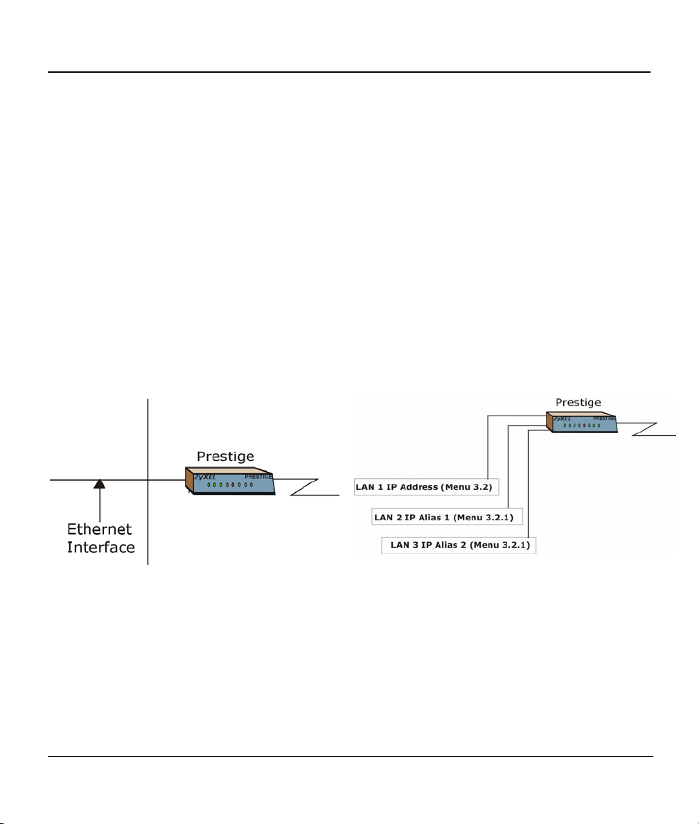
Prestige 324 Intelligent Broadband Sharing Gateway
The address 224.0.0.1 is used for query messages and is assigned to the permanent group of all IP hosts
(including gateways). All hosts must join the 224.0.0.1 group in order to participate in IGMP. The address
224.0.0.2 is assigned to the multicast routers group.
The Prestige supports both IGMP version 1 (IGMP-v1) and IGMP version 2 (IGMP-v2). At start up, the
Prestige queries all directly connected networks to gather group membership. After that, the Prestige
periodically updates this information. IP Multicasting can be enabled/disabled on the Prestige LAN and/or
WAN interfaces using menus 3.2 (LAN) and 11.3 (WAN). Select None to disable IP Multicasting on these
interfaces.
7.2.7 IP Alias
IP Alias allows you to partition a physical network into different logical networks over the same Ethernet
interface. The Prestige supports three logical LAN interfaces via its single physical Ethernet interface with
the Prestige itself as the gateway for each LAN network.
Figure 7-3 Physical Network Figure 7-4 Partitioned Logical Networks
Use menu 3.2.1 to configure IP Alias on your Prestige.
7.3 TCP/IP and DHCP Ethernet Setup
From the main menu, enter 3 to open Menu 3 - LAN Setup (10/100 Mbps Ethernet) to configure TCP/IP
(RFC 1155) and DHCP Ethernet setup.
7-6 LAN Setup
Prestige 324 Intelligent Broadband Sharing Gateway
Menu 3 - LAN Setup
1. LAN Port Filter Setup
2. TCP/IP and DHCP Setup
Enter Menu Selection Number:
Figure 7-5 Menu 3 — LAN Setup (10/100 Mbps Ethernet)
To edit the TCP/IP and DHCP configuration, enter 2 to display Menu 3.2 - TCP/IP and DHCP Ethernet
Setup
as shown next.
Menu 3.2 - TCP/IP and DHCP Ethernet Setup
DHCP= Server
Configuration:
Client IP Pool Starting Address= 192.168.1.33
Size of Client IP Pool= 32
Primary DNS Server= 0.0.0.0
Secondary DNS Server= 0.0.0.0
DHCP Server Address = N/A
TCP/IP Setup:
IP Address= 192.168.1.1
IP Subnet Mask= 255.255.255.0
RIP Direction= Both
Version= RIP-1
Multicast= None
Edit IP Alias= No
Press ENTER to Confirm or ESC to Cancel:
Press Space Bar to Toggle.
First address in
the IP Pool.
Size of the IP
Pool.
IP address of
DNS servers.
The IP address
of the Prestige.
Figure 7-6 Menu 3.2 — TCP/IP and DHCP Ethernet Setup
Follow the instructions in the following table on how to configure the DHCP fields.
LAN Setup 7-7

Prestige 324 Intelligent Broadband Sharing Gateway
Table 7-3 LAN DHCP Setup Menu Fields
FIELD DESCRIPTION EXAMPLE
DHCP
Configuration:
Client IP Pool Starting
Address
Size of Client IP Pool This field specifies the size, or count, of the IP address pool. 32
Primary DNS Server
Secondary DNS
Server
This field enables/disables the DHCP server. If it is set to Server,
your Prestige will act as a DHCP server. If set to None, DHCP
service will be disabled and you must have another DHCP sever
on your LAN, or else the workstation must be manually configured.
When DHCP is set to Server, the following four items need to be
set.
This field specifies the first of the contiguous addresses in the IP
address pool.
Enter the IP addresses of the DNS servers. The DNS servers are
passed to the DHCP clients along with the IP address and the
subnet mask. Leave these entries at 0.0.0.0 if a WAN DHCP
server provides them.
Server
(default)
192.168.1.33
Follow the instructions in the table shown next to configure TCP/IP parameters for the LAN port.
Table 7-4 LAN TCP/IP Setup Menu Fields
FIELD DESCRIPTION EXAMPLE
TCP/IP Setup:
IP Address Enter the IP address of your Prestige in dotted decimal notation 192.168.1.1
(default)
IP Subnet Mask Your Prestige will automatically calculate the subnet mask based on
the IP address that you assign. Unless you are implementing
subnetting, use the subnet mask computed by the Prestige
RIP Direction
Version Press the [SPACE BAR] to select the RIP version.
Multicast IGMP (Internet Group Multicast Protocol) is a session-layer protocol
Press the [SPACE BAR] to select the RIP direction.
Options are Both, In Only, Out Only or None.
Options are RIP-1, RIP-2B or RIP-2M.
used to establish membership in a Multicast group. The Prestige
supports both IGMP version 1 (IGMP-v1) and IGMP-v2. Press the
[SPACE BAR] to enable IP Multicasting or select None (default) to
disable it.
255.255.255.0
Both
(default)
RIP-1
(default)
None
7-8 LAN Setup
Prestige 324 Intelligent Broadband Sharing Gateway
FIELD DESCRIPTION EXAMPLE
Edit IP Alias The Prestige supports three logical LAN interfaces via its single
physical Ethernet interface with the Prestige itself as the gateway for
Yes
each LAN network. Press the [SPACE BAR] to select Yes, then
press [ENTER] to display menu 3.2.1
When you have completed this menu, press [ENTER] at the prompt [Press ENTER to Confirm…] to save
your configuration, or press [ESC] at any time to cancel.
7.3.1 IP Alias Setup
Use menu 3.2 to configure the first network and move the cursor to the Edit IP Alias field and press
[SPACE BAR] to choose Yes and press [ENTER] to configure the second and third network.
Pressing [ENTER] opens Menu 3.2.1 - IP Alias Setup, as shown next.
Menu 3.2.1 - IP Alias Setup
IP Alias 1= No
Enter here to CONFIRM or ESC to CANCEL:
IP Address= N/A
IP Subnet Mask= N/A
RIP Direction= N/A
Version= N/A
Incoming protocol filters= N/A
Outgoing protocol filters= N/A
IP Alias 2= No
IP Address= N/A
IP Subnet Mask= N/A
RIP Direction= N/A
Version= N/A
Incoming protocol filters= N/A
Outgoing protocol filters= N/A
Figure 7-7 Menu 3.2.1 — IP Alias Setup
Follow the instructions in the table shown next to configure IP Alias parameters.
Table 7-5 IP Alias Setup Menu Fields
FIELD DESCRIPTION EXAMPLE
IP Alias
Choose Yes to configure the LAN network for the Prestige. Yes
LAN Setup 7-9

Prestige 324 Intelligent Broadband Sharing Gateway
Table 7-5 IP Alias Setup Menu Fields
FIELD DESCRIPTION EXAMPLE
IP Address Enter the IP address of your Prestige in dotted decimal notation 192.168.2.1
IP Subnet Mask Your Prestige will automatically calculate the subnet mask based on
the IP address that you assign. Unless you are implementing
subnetting, use the subnet mask computed by the Prestige.
RIP Direction Press the [SPACE BAR] to select the RIP direction.
Options are None, Both, In Only or Out Only.
Version Press the [SPACE BAR] to select the RIP version.
Options are RIP-1, RIP-2B or RIP-2M.
Incoming
Protocol Filters
Outgoing
Protocol Filters
When you have completed this menu, press [ENTER] at the prompt [Press ENTER to Confirm…] to save
your configuration, or press [ESC] at any time to cancel.
Enter the filter set(s) you wish to apply to the incoming traffic
between this node and the Prestige.
Enter the filter set(s) you wish to apply to the outgoing traffic between
this node and the Prestige.
255.255.255.0
None
RIP-1
7-10 LAN Setup

Prestige 324 Broadband Sharing Gateway with 4-Port Switch
Chapter 8
Internet Access
This chapter shows you how to configure your Prestige for Internet access.
8.1 Internet Access Setup
You will see three different menu 4 screens depending on whether you chose Ethernet, PPTP or PPPoE
encapsulation.
In the Encapsulation field in menu 4, choose:
Ethernet when the WAN port is used as a regular Ethernet.
PPTP or PPPoE if you have a dial-up connection to the Internet.
8.1.1 Ethernet Encapsulation
You must choose the Ethernet option when the WAN port is used as a regular Ethernet. If you choose
Ethernet in menu 4 you will see the next screen.
IP Static Route Setup 8-1Internet Access
8-1

Prestige 324 Intelligent Broadband Sharing Gateway
Menu 4 - Internet Access Setup
ISP's Name= myISP
Encapsulation= Ethernet
Service Type= Standard
My Login= N/A
My Password= N/A
Login Server IP= N/A
IP Address Assignment= Dynamic
IP Address= N/A
IP Subnet Mask= N/A
Gateway IP Address= N/A
Network Address Translation = SUA Only
Press ENTER to Confirm or ESC to Cancel:
Figure 8-1 Internet Access Setup (Ethernet)
The following table describes this screen.
Table 8-1 Internet Access Setup Menu Fields
FIELD DESCRIPTION
ISP’s Name Enter the name of your Internet Service Provider, e.g., myISP. This
information is for identification purposes only.
Encapsulation
Service Type This is applicable only when you choose Ethernet as your encapsulation
Note: xDSL users must choose the Standard option only. The Server IP, My Login IP and My
Password fields are not applicable in this case.
My Login Enter the login name given to you by your ISP.
My Password Enter the password associated with the login name above.
Login Server IP The Prestige will find the RoadRunner Server IP if this field is left blank. If it
Press the [SPACE BAR] and then press [ENTER] to choose Ethernet. The
encapsulation method influences your choices for IP Address.
method. Press the [SPACE BAR] to select Standard, RR-Toshiba
(RoadRunner Toshiba authentication method), RR-Manager (RoadRunner
Manager authentication method) or RR-Telstra (RoadRunner Telstra
authentication method). Choose a RoadRunner service type if your ISP is
Time Warner's RoadRunner; otherwise choose Standard.
does not, then you must enter the authentication server IP address.
8-2 Internet Access

Prestige 324 Broadband Sharing Gateway with 4-Port Switch
Table 8-1 Internet Access Setup Menu Fields
FIELD DESCRIPTION
IP Address Assignment
IP Address Enter the (fixed) IP address assigned to you by your ISP (Static IP Address
IP Subnet Mask Enter the subnet mask associated with your static IP.
Gateway IP Address Enter the gateway IP address associated with your static IP.
Network Address
Translation
Once you have finished configuring a rule in this menu, press [ENTER] at the message “Press ENTER to
Confirm…” to save your configuration, or press [ESC] to cancel.
If your ISP did not assign you a fixed IP address, select Dynamic, otherwise
select Static and enter the IP address & subnet mask in the following fields.
Assignment is selected in the previous field).
Refer to the following chapter for a more detailed discussion on the Single
User Account and NAT. Options are SUA only, Full Feature or None.
8.1.2 PPTP Encapsulation
Point-to-Point Tunneling Protocol (PPTP) is a network protocol that enables transfer of data from a remote
client to a private server, creating a Virtual Private Network (VPN) using TCP/IP-based networks.
PPTP supports on-demand, multi-protocol, and virtual private networking over public networks, such as the
Internet.
The P324 supports one PPTP server connection at any given time.
8.1.3 Configure PPTP Client
To configure a PPTP client, you must configure My Login and Password fields for PPP connection and
PPTP parameters for PPTP connection.
After configuring the User Name and Password for PPP connection, press [SPACE BAR] in the
Encapsulation field in Menu 4 -Internet Access Setup to choose PPTP as your encapsulation option.
If you choose PPTP in menu 4 you will see the next screen.
IP Static Route Setup 8-3Internet Access
8-3

Prestige 324 Intelligent Broadband Sharing Gateway
Menu 4 - Internet Access Setup
ISP's Name= myISP
Encapsulation= PPTP
Service Type= N/A
My Login=
My Password= ******
Idle Timeout= 300
IP Address Assignment= Dynamic
IP Address= N/A
IP Subnet Mask= N/A
Gateway IP Address=N/A
Network Address Translation = SUA Only
Press ENTER to Confirm or ESC to Cancel:
Figure 8-2 Internet Access Setup (PPTP)
The following table contains instructions about the new fields when you choose PPTP in the
Encapsulation field in menu 4.
Table 8-2 New Fields in Menu 4 (PPTP) screen
FIELD DESCRIPTION EXAMPLE
Encapsulation Press the [SPACE BAR] and then press [ENTER] to choose
PPTP
PPTP. The encapsulation method influences your choices for
IP Address.
Idle Timeout This value specifies the time in seconds that elapses before
the Prestige automatically disconnects from the PPTP server.
300
(default)
8.1.4 PPPoE Encapsulation
The Prestige supports PPPoE (Point-to-Point Protocol over Ethernet). You can use PPPoE encapsulation
only when you’re using the Prestige with an xDSL modem as the WAN device.
PPPoE is an IETF Draft standard specifying how a host personal computer interacts with a broadband
modem (i.e. xDSL, cable, wireless, etc.) to achieve access to high-speed data networks. It preserves the
existing Microsoft Dial-Up Networking experience and requires no new learning or procedures.
For the service provider, PPPoE offers an access and authentication method that works with existing access
control systems (e.g., Radius). For the user, PPPoE provides a login and authentication method that the
existing Microsoft Dial-Up Networking software can activate, and therefore requires no new learning or
8-4 Internet Access

Prestige 324 Broadband Sharing Gateway with 4-Port Switch
procedures for Windows users.
One of the benefits of PPPoE is the ability to let end users access one of multiple network services, a
function known as dynamic service selection. This enables the service provider to easily create and offer
new IP services for specific users.
Operationally, PPPoE saves significant effort for both the end user and ISP/carrier, as it requires no specific
configuration of the broadband modem at the customer site.
By implementing PPPoE directly on the Prestige (rather than individual computers), the computers on the
LAN do not need PPPoE software installed, since the Prestige does that part of the task. Furthermore, with
NAT, all of the LAN’s computers will have access.
If you enable PPPoE in menu 4, you will see the next screen. For more information on PPPoE, please refer
to the PPPoE Appendix.
Menu 4 - Internet Access Setup
ISP's Name= myISP
Encapsulation= PPPoE
Service Type= N/A
My Login=
My Password= ********
Idle Timeout= 300
IP Address Assignment= Dynamic
IP Address= N/A
IP Subnet Mask= N/A
Gateway IP Address= N/A
Network Address Translation = SUA Only
Press ENTER to Confirm or ESC to Cancel:
Figure 8-3 Internet Access (PPPoE)
IP Static Route Setup 8-5Internet Access
8-5

Prestige 324 Intelligent Broadband Sharing Gateway
Table 8-3 New Fields in Menu 4 (PPPoE) screen
FIELD DESCRIPTION EXAMPLE
Encapsulation Press the [SPACE BAR] and then press [ENTER] to choose
PPPoE
PPPoE. The encapsulation method influences your choices
for IP Address.
Idle Timeout This value specifies the time in seconds that elapses before
the Prestige automatically disconnects from the PPPoE
300
(default)
server.
8.2 Internet Test Setup
After configuring the menu 4 fields when you press [ENTER] to confirm you will see the message, " Do
you wish to perform the Internet Setup Test[y/n]:" if you have chosen PPTP or PPPoE as your
encapsulation method. Say 'Y' to test your setup. An example of Internet Setup Test is shown next.
Start dialing for node <ChangeMe>...
### Hit any key to continue.###
$$$ DIALING dev=a ch=0..........
$$$ OUTGOING-CALL phone()
$$$ PPTP: Start tunnel setup, send SCCRQ
$$$ PPTP: OCRQ sent
$$$ CALL CONNECT speed<10000000> type<10> chan<0>
$$$ LCP opened
$$$ CHAP login to remote OK
$$$ IPCP negotiation started
$$$ CCP stopped
$$$ BACP stopped
$$$ IPCP neg' Primary DNS 202.xxx.xxx.x
$$$ IPCP opened
Figure 8-4 Internet Setup Test Example
8-6 Internet Access


PPaarrtt IIII::
Advanced Applications
This section describes the advanced applications of your Prestige, such as NAT, Remote Node
Setup and IP Static Route Setup.
II

Prestige 324 Intelligent Broadband Sharing Gateway
Chapter 9
Remote Node Setup
This chapter shows you how to configure menu 11 and all its sub-menus including traffic redirect.
9.1 Introduction
A remote node is required for placing calls to a remote gateway. A remote node represents both the remote
gateway and the network behind it across a WAN connection. Note that when you use menu 4 to set up
Internet access, you are actually configuring a remote node. We will show you how to configure Menu
11.1 Remote Node Profile, Menu 11.3 - Remote Node Network Layer Options and Menu 11.5 -
Remote Node Filter.
9.2 Remote Node Profile
From the main menu, select option 11 to display Menu 11.1 - Remote Node Profile. There are three
variations of this menu depending on whether you choose Ethernet Encapsulation, PPTP or PPPoE
Encapsulation.
9.2.1 Ethernet Encapsulation
Choose the Ethernet option when the WAN port is used as a regular Ethernet. The first menu 11.1 screen
you see is for Ethernet Encapsulation shown next.
Remote Node Setup 9-1

Menu 11.1 - Remote Node Profile
Rem Node Name= ChangeMe Route= IP
Active= Yes
Encapsulation= Ethernet Edit IP= No
Service Type= Standard Session Options:
Service Name= N/A Edit Filter Sets= No
Outgoing:
My Login= N/A Edit Traffic Redirect= No
My Password= N/A
Server IP= N/A
Press ENTER to Confirm or ESC to Cancel.
Figure 9-1 Menu 11.1 Remote Node Profile for Ethernet Encapsulation
Table 9-1 Fields in Menu 11.1 (Ethernet Encapsulation)
FIELD DESCRIPTION EXAMPLE
Rem Node
Name
Active
Encapsulation
Service Type
Service Type
Note: xDSL users must choose the Standard option only. The Server IP, My Login IP and My Password
fields are not applicable in this case.
Enter a descriptive name for the remote node. This field can be up to eight
characters.
Press [SPACE BAR] to select Yes (activate remote node) or No
(deactivate remote node).
Ethernet is the default encapsulation. Press [SPACE BAR] if you wish to
change to PPPoE or PPTP encapsulation.
Press [SPACE BAR] to select from Standard, RR-Toshiba
(RoadRunner Toshiba authentication method), RR-Manager
(RoadRunner Manager authentication method) or, RR-Telstra
(RoadRunner Telstra authentication method). Choose one of the
RoadRunner methods if your ISP is Time Warner's RoadRunner;
otherwise choose Standard.
Press [SPACE BAR] to select from Standard, RR-Toshiba (RoadRunner
Toshiba authentication method), RR-Manager (RoadRunner Manager
authentication method) or, RR-Telstra (RoadRunner Telstra
authentication method). Choose one of the RoadRunner methods if your
ISP is Time Warner's RoadRunner; otherwise choose Standard.
LAoffice
Yes
Ethernet
Standard
Standard
9-2 Remote Node Setup

Prestige 324 Intelligent Broadband Sharing Gateway
Table 9-1 Fields in Menu 11.1 (Ethernet Encapsulation)
FIELD DESCRIPTION EXAMPLE
Service Name
This is valid only when you have chosen PPPoE encapsulation. If you are
using PPPoE encapsulation, then type the name of your PPPoE service
here.
poellc
Outgoing
My Login
My Password Enter the password assigned by your ISP when the Prestige calls this
Server IP This field is valid for RoadRunner service type only. The Prestige will find
Route This field refers to the protocol that will be routed by your Prestige – IP is
Edit IP
Session
Options
Edit Filter
Once you have configured the Remote Node Profile Menu, press [ENTER] to return to menu 11. Press
[ENTER] at the message “Press ENTER to Confirm...” to save your configuration, or press [ESC] at any time
to cancel.
This field is applicable for PPPoE encapsulation only. Enter the login
name assigned by your ISP when the Prestige calls this remote node.
Some ISPs append this field to the Service Name field above (e.g.,
jim@poellc) to access the PPPoE server.
remote node. Valid for PPPoE encapsulation only.
the RoadRunner Server IP automatically if this field is left blank. If it does
not, then you must enter the authentication server IP address here.
the only option for the Prestige 10.
This field leads to a “hidden” menu. Press [SPACE BAR] to select Yes
and press [ENTER] to go to Menu 11.3 - Remote Node Network Layer
Options.
This field leads to another “hidden” menu. Use the [SPACE BAR] to select
Yes and press [ENTER] to open menu 11.5 to edit the filter sets. See the
Remote Node Filter section for more details.
sets
jim
*****
IP
Yes
Yes
9.2.2 PPTP Encapsulation
If you change the Encapsulation to PPTP in Menu 11.1, then you will see the next screen. Please see the
appendix for information.
Remote Node Setup 9-3
 Loading...