

Page 1
P-2900-4HB
Cable Router
Default Login Details
IP Address 192.168.1.1
Password 1234
Firmware Version 3.40
Edition 1, 3/2009
www.zyxel.com
www.zyxel.com
Copyright © 2009
ZyXEL Communications Corporation
Page 2

Page 3

About This User's Guide
About This User's Guide
Intended Audience
This manual is intended for people who want to configure the Zy XEL Device using
the web configurator. You should have at least a basic knowledge of TCP/IP
networking concepts and topology.
Related Documentation
•Quick Start Guide
The Quick Start Guide is designed to help you get up and running right away. It
contains information on setting up your network and configuring for Internet
access.
• Support Disc
Refer to the included CD for support documents.
• ZyXEL Web Site
Please refer to www.zyxel.com
product certifications.
for additional support documentation and
User Guide Feedback
Help us help you. Send all User Guide-related comments, questi ons or suggestions
for improvement to the following address, or use e-mail instead. Thank you!
The Technical Writing Team,
ZyXEL Communications Corp.,
6 Innovation Road II,
Science-Based Industrial Park,
Hsinchu, 300, Taiwan.
E-mail: techwriters@zyxel.com.tw
Customer Support
In the event of problems that cannot be solved by using this manual, you should
contact your vendor. If you cannot contact your vendor, then contact a ZyXEL
office for the region in which you bought the device. See ht t p ://www.zyxel.com/
web/contact_us.php for contact information. Please have the following information
ready when you contact an office.
• Product model and serial number.
•Warranty Information.
P-2900-4HB User’s Guide
3
Page 4

About This User's Guide
• Date that you received your device.
• Brief description of the problem and the steps you took to solve it.
4
P-2900-4HB User’s Guide
Page 5

Document Conventions
Document Conventions
Warnings and Notes
These are how warnings and notes are shown in this User’s Guide.
Warnings tell you about things that could harm you or your device.
Note: Notes tell you other important information (for example, other things you may
need to configure or helpful tips) or recommendations.
Syntax Conventions
• The P-2900-4HB may be referred to as the “ZyXEL Device”, the “device” or the
“system” in this User’s Guide.
• Product labels, screen names, field labels and field choices are all in bold font.
• A key stroke is denoted by square brackets and uppercase text, for example,
[ENTER] means the “enter” or “ret urn” key on your keyboard.
• “Enter” means for you to type one or more characters and then press the
[ENTER] key. “Select” or “choose” means for you to use one of the predefined
choices.
• A right angle bracket ( > ) within a screen name denotes a mouse click. For
example, Maintenance > Log > Log Setting means you first click
Maintenance in the navigation panel, then the Log sub menu and finally the
Log Setting tab to get to that screen.
• Units of measurement may denote the “metric” value or the “scientific” value.
For example, “k” for kilo may denote “1000” or “1024”, “M” for mega may
denote “1000000” or “1048576” and so on.
• “e.g.,” is a shorthand for “for instance”, and “i.e.,” means “that is” or “in other
words”.
P-2900-4HB User’s Guide
5
Page 6
Document Conventions
Icons Used in Figures
Figures in this User’s Guide may use the following generic icons. The Z yXEL Device
icon is not an exact representation of your device.
ZyXEL Device Computer Notebook computer
Server Telephone Switch
Router Internet
6
P-2900-4HB User’s Guide
Page 7

Safety Warnings
Safety Warnings
• Use only No. 26 AWG (American Wire Gauge) or larger telecommunication line cord.
• Do NOT use this product near water, for example, in a wet basement or near a swimming
pool.
• Do NOT expose your device to dampness, dust or corrosive liquids.
• Do NOT store things on the device.
• Do NOT install, use, or service this device during a thunderstorm. There is a remote risk
of electric shock from lightning.
• Connect ONLY suitable accessories to the device.
• Do NOT open the device or unit. Opening or removing covers can expose you to
dangerous high voltage points or other risks. ONLY qualified service personnel should
service or disassemble this device. Please contact your vendor for further information.
• Make sure to connect the cables to the correct ports.
• Place connecting cables carefully so that no one will step on them or stumble over them.
• Always disconnect all cables from this device before servicing or disassembling.
• Use ONLY an appropriate power adaptor or cord for your device.
• Connect the power adaptor or cord to the right supply voltage (for example, 110V AC in
North America or 230V AC in Europe).
• Do NOT allow anything to rest on the power adaptor or cord and do NOT place the
product where anyone can walk on the power adaptor or cord.
• Do NOT use the device if the power adaptor or cord is damaged as it might cause
electrocution.
• If the power adaptor or cord is damaged, remove it from the power outlet.
• Do NOT attempt to repair the power adaptor or cord. Contact your local vendor to order a
new one.
• Do not use the device outside, and make sure all the connections are indoors. There is a
remote risk of electric shock from lightning.
• Do NOT obstruct the device ventilation slots, as insufficient airflow may harm your
device.
• Antenna Warning! This device meets FCC certification requirements when using the
included antenna(s). Only use the included antenna(s).
• Make sure that the cable system is grounded so as to provide some protection against
voltage surges.
• CAUTION: RISK OF EXPLOSION IF BATTERIES ARE REPLACED BY AN INCORRECT TYPE.
DISPOSE OF USED BA TTERIES AC CORDING TO THE INSTRUC TIONS. Dispose them at the
applicable collection point for the recycling of electrical and electronic equipment. For
detailed information about recycling of this product, please contact your local city office,
your household waste disposal service or the store where you purchased the product.
Your product is marked with this symbol, which is known as the WEEE mark. WEEE
stands for Waste Electronics and Electrical Equipment. It means that used electrical
and electronic products should not be mixed with general waste. Used electrical and
electronic equipment should be treated separately.
P-2900-4HB User’s Guide
7
Page 8

Safety Warnings
8
P-2900-4HB User’s Guide
Page 9

Contents Overview
Contents Overview
Introduction and Configuration ............................................................................................15
Getting To Know Your ZyXEL Device ........................................................................................ 17
Introducing the Web Configurator .............................................................................................. 21
Status ............................................................... ...................... ....................... ............................. 27
Tutorials ..................................................................................................................................... 39
Advanced Setup .....................................................................................................................47
LAN Setup .................................................................................................................................49
Network Address Translation (NAT) Screens ............................................................................59
Dynamic DNS Setup .................................................................................................................. 67
Static IP .....................................................................................................................................69
Remote Management Configuration ......................... ....................... .......................... ................ 71
Logs ....................................... .................................................... ................................................ 75
Maintenance and Troubleshooting .......................................................................................81
Maintenance .............................................................................................................................. 83
Product Specification, Appendices and Index ....................................................................87
Troubleshooting ..................................................... .................................................................... 89
P-2900-4HB User’s Guide
9
Page 10

Contents Overview
10
P-2900-4HB User’s Guide
Page 11

Table of Contents
Table of Contents
About This User's Guide..........................................................................................................3
Document Conventions............................................................................................................5
Safety Warnings ........................................................................................................................7
Contents Overview ...................................................................................................................9
Table of Contents....................................................................................................................11
Part I: Introduction and Configuration................................................. 15
Chapter 1
Getting To Know Your ZyXEL Device....................................................................................17
1.1 Overview ............. ............................................. ... .... ... ... ... .... ................................................ 17
1.2 Hardware Connection and Installation .................................... ................................ ............. 17
1.3 LEDs (Lights) ......................... .... ... ... ............................................. ... .... ... ... ... .... ... ................ 18
1.4 USB Port .......................................................... ... .... ... ... ... .... ................................................ 19
1.5 Battery Packs ............................................................................... ... .... ... ............................. 19
Chapter 2
Introducing the Web Configurator ........................................................................................21
2.1 Overview ............. ............................................. ... .... ... ... ... .... ................................................ 21
2.2 Accessing the Web Configurator ......................................................................................... 22
2.2.1 Resetting the ZyXEL Device ...................................................................................... 23
2.3 Navigating the Web Configurator ............................................... .......................................... 23
2.4 Change Login Password ............................. ... ... .... ... ... ... ............................................. .... ... 24
Chapter 3
Status.......................................................................................................................................27
3.1 Overview ............. ............................................. ... .... ... ... ... .... ................................................ 27
3.2 What You Can Do in the Status Screens .............................................................................27
3.2.1 What You Need to Know About Status ... ... .... ... ... ... .... ... ... ... ... .... ... ............................. 27
3.3 The System Status Screen ........................ ... ... ... .... ... ... ... .... ... ... ... ... .................................... 30
3.4 The Cable Modem Status Screen ........................................................................................32
3.4.1 What You Need to Know About Cable Modem Status ............................................... 32
3.4.2 Viewing the Cable Modem Status Screen .................................................................. 33
3.5 The MTA Status Screen ................................ ... ... .... ... ... ... .... ... ............................................. 36
P-2900-4HB User’s Guide
11
Page 12

Table of Contents
Chapter 4
Tutorials...................................................................................................................................39
4.1 Overview ............. ............................................. ... .... ... ... ... .... ................................................ 39
4.2 Access the ZyXEL Device Using DDNS .............................................................................. 39
4.2.1 Registering a DDNS Account on www.dyndns.org .................................................... 40
4.2.2 Configuring DDNS on Your ZyXEL Device ................................................................. 40
4.2.3 Testing the DDNS Setting .......................................................................................... 41
4.3 Multiple WAN Configuration .................................................................................................41
4.3.1 Network Setup and IP Settings ................. .... ... ... ... .... ... ... ... ... .... ... ............................. 42
4.3.2 Configuring Static IP Addresses ....................................................... ................ .......... 43
4.3.3 Configuring NAT ........................ ............................................. .... ... ... ... .... ... ... ... ... .... ... 44
4.3.4 Access the Web/FTP Services from the Internet ....................................................... 46
Part II: Advanced Setup......................................................................... 47
Chapter 5
LAN Setup................................................................................................................................49
5.1 Overview ............... ............................................. .... ... ... ... .... ... ............................................. 49
5.1.1 What Yo u Can Do in the LAN Screens ....................................................................... 49
5.1.2 What You Need To Know About LAN .................................. ... .... ... ... ... .... ... ... ... ... .... ... 49
5.1.3 Before You Begin ....................................................................................................... 50
5.2 The LAN Setup Screen ........................................................................................................51
5.3 The Static DHCP Screen ....................................................................................................52
5.4 LAN Technical Reference .......... ..........................................................................................54
5.4.1 DHCP Setup ..................... ... ... ... ... .... ... ... ... .............................................. ... ... ... ... .... ...54
5.4.2 DNS Server Address ................................. .... ... ... ... ............................................. .... ... 54
5.4.3 LAN TCP/IP .................. .... ... ... ............................................. ... .... ... ............................. 54
5.4.4 RIP Setup ............................................................................... .... ... ... ... .... ... ... .............56
5.4.5 Multicast . ... ... ... .............................................. ... ... ... ............................................. ....... 56
Chapter 6
Network Address Translation (NAT) Screens.......................................................................59
6.1 Overview ............... ............................................. .... ... ... ... .... ... ............................................. 59
6.1.1 What You Can Do in the NAT Screen ........................................................................ 59
6.1.2 What You Need to Know About NAT ... ... ... .... ... ... ... .... ................................................ 59
6.2 The NAT Mode Screen ........................................................................................................60
6.2.1 Configuring Address Mapping Rules ......................................................................... 60
6.2.2 Editing an Address Mapping Rule ............................................................................. 62
6.3 NAT Technical Reference ....................................................................................................63
6.3.1 NAT Definitions ......... ... .... ... ... ... ... .............................................. ... ... ... .... ... ... ... ..........63
6.3.2 What NAT Does ........... .... ... ... ... ... .... ............................................. ... ... .... ... ... ... .......... 64
12
P-2900-4HB User’s Guide
Page 13

Table of Contents
6.3.3 How NAT Works .........................................................................................................64
6.3.4 NAT Mapping Types ...................................... ... ... ... ............................................. .... ... 65
Chapter 7
Dynamic DNS Setup ...............................................................................................................67
7.1 Overview ............... ............................................. .... ... ... ... .... ... ............................................. 67
7.1.1 What You Can Do in the Dynamic DNS Screen ......................................................... 67
7.1.2 What You Need to Know About Dynamic DNS ................................ ... .... ... ... ... ... .... ... 67
7.2 The Dynamic DNS Screen .................................................................................................. 68
Chapter 8
Static IP....................................................................................................................................69
8.1 Overview ............... ............................................. .... ... ... ... .... ... ............................................. 69
8.2 The Static IP Screen .............. .... ... ... ... ... .... ... ... ... ................................................................. 69
Chapter 9
Remote Management Configuration.....................................................................................71
9.1 Overview ............... ............................................. .... ... ... ... .... ... ............................................. 71
9.1.1 What You Can Do in the Remote Management Screen .............................................72
9.2 The Remote Management Screen ............................................... ... .... ... ... ... .... ... ... ... ... .... ... 72
9.2.1 Firmware Upgrade Example ...................................................................................... 73
9.3 Remote Management Technical Reference ........................................................................ 74
9.3.1 Remote Management Limitations .............................................................................. 74
9.3.2 Remote Management and NAT ..................................................... ... ... .... ... ... ... ... .... ... 74
9.3.3 System Timeout .......... .............................................. ... ... ... ... .... ... ... .......................... 74
Chapter 10
Logs .........................................................................................................................................75
10.1 Overview ........................................................................................................................... 75
10.1.1 What You Can Do in the Log Screens ...................................................................... 75
10.1.2 What You Need to Know About Logs ....................................................................... 75
10.2 The Log Settings Screen ..... .... ... ...... ... .... ..........................................................................76
10.3 The View Logs Screen ...................................................................................................... 78
10.3.1 Email Log Example .................................................................................................. 78
Part III: Maintenance and Troubleshooting ......................................... 81
Chapter 11
Maintenance............................................................................................................................83
11.1 Overview ............................................................................................................................ 83
11.2 What You Can Do in this Chapter ...................................................................................... 83
P-2900-4HB User’s Guide
13
Page 14

Table of Contents
11.3 The DHCP Table Screen ...................................................................................................83
11.4 The Diagnostics Screen ..................................................................................................... 85
Part IV: Product Specification, Appendices and Index ...................... 87
Chapter 12
Troubleshooting......................................................................................................................89
12.1 Overview ............................................................................................................................ 89
Appendix A Product Specifications.........................................................................................91
Appendix B Setting up Your Computer’s IP Address..............................................................97
Appendix C Common Services ............................................................................................115
Appendix D Legal Information..............................................................................................119
Index.......................................................................................................................................123
14
P-2900-4HB User’s Guide
Page 15

PART I
Introduction and
Configuration
Getting To Know Your ZyXEL Device (17)
Introducing the Web Configurator (21)
Status (27)
15
Page 16

16
Page 17
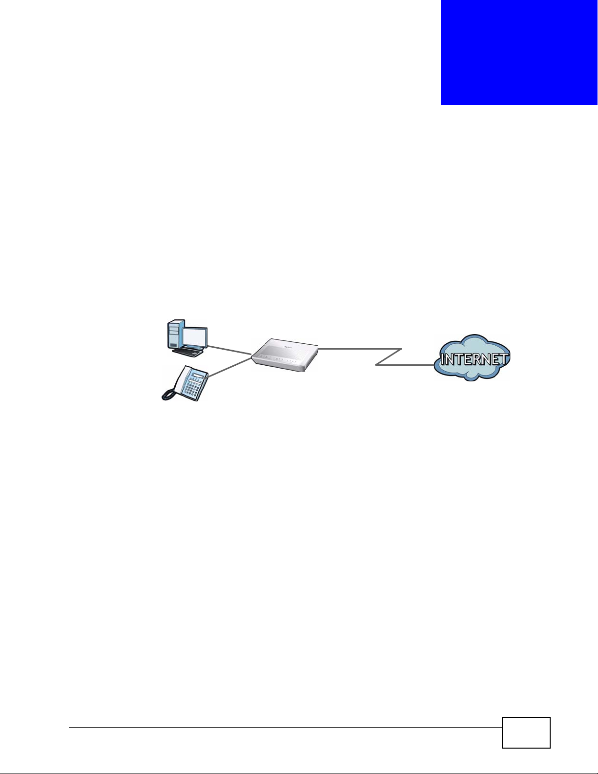
CHAPTER 1
Getting To Know Your ZyXEL
Device
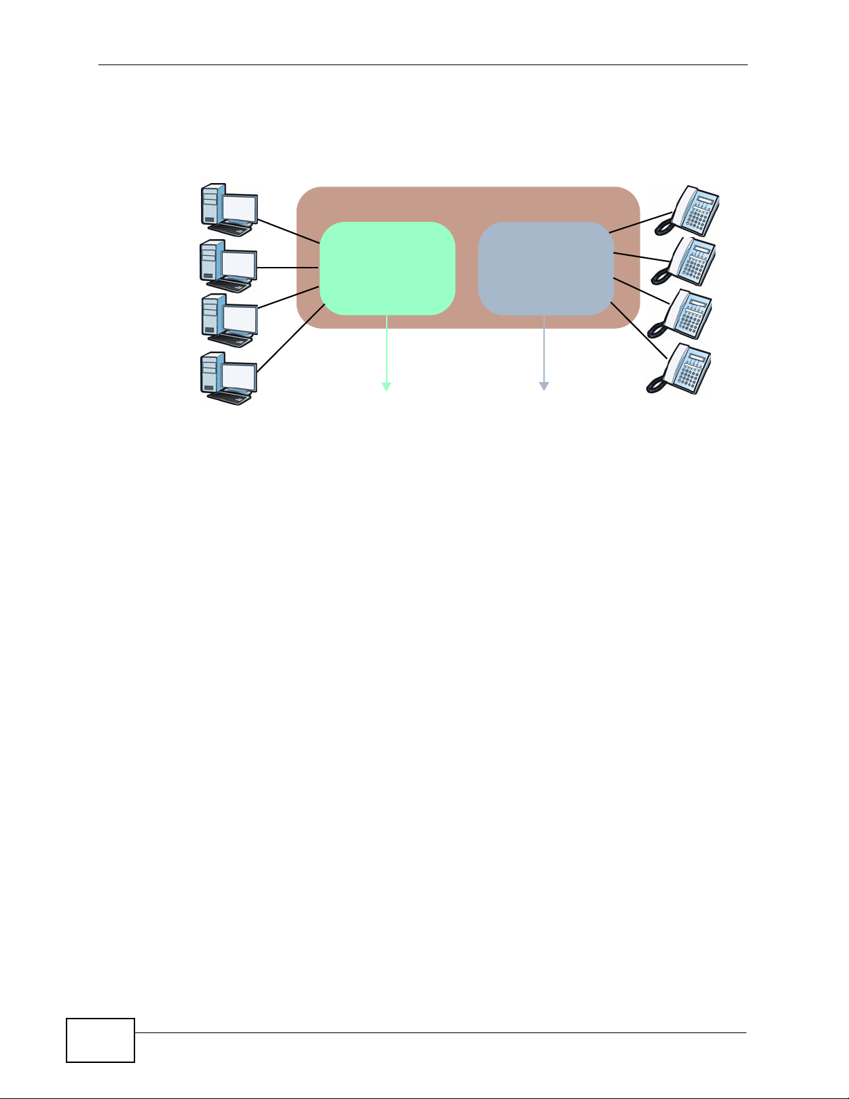
This chapter describes the key features and applications of your ZyXEL Device.
1.1 Overview
The ZyXEL Device is an embedded Multimedia Terminal Adapter (eMTA) device
built with two components: a DOCSIS 2.0 cable modem component for data
transfer and a PacketCable 1.5 MTA component for voice traffic. This means it can
provide high-speed Internet access as well as cost-effective, standard telephone
voice and fax/modem services through your cable service provider.
You can connect your computer to the ZyXEL Device either through a LAN or the
USB port. Connect your telephones to the PHONE ports if your VoIP company
gave you phone numbers.
Figure 1 Internet Access Application
LAN
PHONE
USB
1.2 Hardware Connection and Installation
Refer to the Quick Start Guide for information about hardware connections and
USB driver installation.
P-2900-4HB User’s Guide
17
Page 18
Chapter 1 Getting To Know Your ZyXEL Device
1.3 LEDs (Lights)
The following figure displays the labels of the LED.
Figure 2 Front Panel LEDs
The following table describes the LEDs.
Table 1 Front Panel LEDs
LED COLOR STATUS DESCRIPTION
PWR Green On The ZyXEL Device is receiving AC power.
Blinking The ZyXEL Device is receiving sufficient power
Off The ZyXEL Device is not receiving power or it is
DS Green On The ZyXEL Device has successfully found a
Blinking The ZyXEL Device is trying to search for a
Off The downstream channel is not found.
US Green On The ZyXEL Device has successfully found an
Blinking The ZyXEL Device is trying to search for an
Off The upstream channel is not found.
ONLINE Green On The ZyXEL Device has successfully established a
Blinking Slowly: The ZyXEL Device is trying to initiate a
from the battery.
starting up.
downstream channel.
downstream channel.
upstream channel.
upstream channel.
connection to the cable operator’s network.
connection with the cable operator’s network.
18
Fast: The ZyXEL Device is sending/receiving data
on the WAN.
Off The coaxial cable is not connected or the cable link
is down.
LAN 1-4 Green On The ZyXEL Device has a successful 10/100Mb
Ethernet connection.
Blinking The ZyXEL Device is sending/receiving data.
Off The LAN is not connected.
P-2900-4HB User’s Guide
Page 19
Chapter 1 Getting To Know Your ZyXEL Device
Table 1 Front Panel LEDs (continued)
LED COLOR STATUS DESCRIPTION
USB Green On A computeris connected to the USB port on the
ZyXEL Device. See Section 1.4 on page 19 for
more information about the USB port.
Blinking The ZyXEL Device is sending/receiving data via
the USB port.
Off The USB port is not connected.
PHONE 1-4 Green On The ZyXEL Device has successfully registered to
an IP telephone network.
Blinking The phone port is in use or is getting VoIP settings
from the MTA auto-provisioning serv er.
Off The phone port is not connected or has not yet
connected to the MTA auto-provisioning server.
BATTERY Green On • The ZyXEL Device is starting up.
• The battery has sufficient power and the ZyXEL
Device is using AC power. The LED turns off if
the ZyXEL Device uses battery power.
Blinking The battery power is low.
Off • The ZyXEL Device is receiving sufficient power
from the battery if the PWR LED is blinking at
the same time.
• The ZyXEL Device is not receiving power from
the battery nor AC power.
1.4 USB Port
The USB port is useful if you have an USB-enabled computer that does not have a
network interface card available for attaching to the ZyXEL Device’s LAN network.
See the Quick Start Guide for details about USB driver installation pr oc ed ures.
1.5 Battery Packs
You can inst all up to two optional battery packs in the ZyXEL Device’ s battery bay.
This will ensure that any phones attached to the device during a power outage will
continue to function for a time. See the Quick Start Guide for details about battery
packs intallation procedures.
The standby time for a single battery is approximately 8 hours while the usage
time is approximately 5 hours.
Note: The device cannot function when there is
a power outage.
P-2900-4HB User’s Guide
19
Page 20

Chapter 1 Getting To Know Your ZyXEL Device
Note: When the battery is in use, you can only make VoIP calls. Ethernet connections
will not function.
Note: Battery packs are sold separately.
20
P-2900-4HB User’s Guide
Page 21

CHAPTER 2
Introducing the Web
Configurator
This chapter describes how to access the ZyXEL Device web configurator and
provides an overview of its screens.
2.1 Overview
The web configurator is an HTML-based management interface that allows easy
setup and management via an Internet browser. Use Internet Explorer 6.0 and
later or Netscape Navigator 7.0 and later versions. The recommended screen
resolution is 1024 by 768 pixels.
In order to use the web configurator you need to allow:
• Web browser pop -up windows from your device. W eb pop-up blocking is enabl ed
by default in Windows XP SP (Service Pack) 2.
• JavaScripts (enabled by default).
• Java permissions (enabled by default).
See the chapter on troubleshooting to see how to make sure these functions are
allowed in Internet Explorer.
P-2900-4HB User’s Guide
21
Page 22
Chapter 2 Introducing the Web Configurator
2.2 Accessing the Web Configurator
Follow the steps below to log into the Web Configurator.
1 Launch your web browser. Enter “192.168.1.1” as the web site address.
Figure 3 Web browser URL screen.
2 A login screen displays. Enter the password (“1234” by default) and click Login.
Figure 4 Web Configurator login screen
3 It is highly recommended you change the default password! Enter a new password
between 1 and 30 characters, retype it to confirm and click Apply; alternatively
click Ignore to proceed to the main menu if you do not want to change the
password now.
If you do not change the password at least once, the following screen appears
every time you log in.
Figure 5 Change Password at Login
4 You should now see the main Site Map screen (refer to Figure 6 on page 23).
22
P-2900-4HB User’s Guide
Page 23
2.2.1 Resetting the ZyXEL Device
If you forget your password or cannot access the web configurator, you will need
to use the RESET button at the back of the ZyXEL Device to reload the factorydefault configuration file. This means that you will lose all configurations that you
had previously and the password will be reset to “1234”.
2.2.1.1 Using the RESET Button
1 Make sure the PWR LED is on (not blinking).
2 Press and hold the RESET button for about 15 seconds. All LEDs should turn on.
When you release the RESET button, the defaults have been restored and the
ZyXEL Device restarts.
You can also use the RESET button to restart the ZyXEL Device (without restoring
the defaults) by pressing down for 2 to 14 seconds.
Chapter 2 Introducing the Web Configurator
2.3 Navigating the Web Configurator
The following section summarizes how to navigate the web configurator from the
main Status screen.
Figure 6 Status
P-2900-4HB User’s Guide
23
Page 24
Chapter 2 Introducing the Web Configurator
Following table lists the menu screens.
Table 2 Web Configurator Screens Summary
LINK SUB-LINK FUNCTION
Status System Status Use this screen to view firmware and system related
CableModem
Status
MTA Status Use this screen to view information about MTA and
Advanced Setup
Password Use this screen to change your password.
LAN LAN Setup Use this screen to configure LAN DHCP and TCP/IP
Static DHCP Use this screen to configure static DHCP settings.
NAT Use this screen to enable or disable Network Address
Dynamic DNS Use this screen to set up dynamic DNS.
Static IP Use this screen to configure up to three static WAN IP
Remote
Management
Logs Log Settings Use this screen to change your ZyXEL Device’s log
View Log Use this screen to view the logs for the categories that
Maintenance DHCP Table This screen lists the DHCP clients connected to the
Diagnostic These screen displays information to help you identify
Logout Click this to exit the Web Configurator.
information.
Use this screen to view information about the cable
modem, upstream and downstream channels.
status about the VoIP ports.
settings.
Translation (NAT). You can also use this screen to
configure rules the ZyXEL Device uses to convert
between private to public IP addresses.
addresses and RIP settings. Configure a static IP
address only if your cable service provider gave you
the information. See Section 4.3 on page 41 for a
configuration example.
Use this screen to configure through which interface(s)
and from which IP address(es) users can use Telnet/
FTP/Web to manage the ZyXEL Device.
settings.
you selected.
ZyXEL Device.
problems with the ZyXEL Device general connection.
2.4 Change Login Password
It is highly recommended that you periodically change the password for accessing
the ZyXEL Device. If you didn’t change the default one after you logged in or you
24
P-2900-4HB User’s Guide
Page 25

Chapter 2 Introducing the Web Configurator
want to change to a new password again, then click Password in the Site Map
screen to display the screen as shown next.
Figure 7 Password
The following table describes the fields in this screen.
Table 3 Password
LABEL DESCRIPTION
Old Password Type the default password or the existing password you use to access
the system in this field.
New Password Type the new password in this field.
Retype to
Confirm
Apply Click Apply to save your changes back to the Prestige.
Cancel Click Cancel to begin configuring this screen afresh.
Type the new password again in this field.
P-2900-4HB User’s Guide
25
Page 26

Chapter 2 Introducing the Web Configurator
26
P-2900-4HB User’s Guide
Page 27

CHAPTER 3
Status
3.1 Overview
This chapter describes the status screens you can display the ZyXEL Device’s
firmware and system information.
3.2 What You Can Do in the Status Screens
•Use the System Status screen (see Section 3.3 on page 30) to view firmware,
LAN and WAN information.
•Use the Cable Modem Status screen (see Section 3.4 on page 32) to view
status information about the cable modem, upstream and downstream
channels.
•Use the MTA Status screen (see Section 3.5 on page 36) to view status
information about the VoIP module and the phone ports.
3.2.1 What You Need to Know About Status
CM and MTA
The ZyXEL Device functions as two independent units: the cable modem part and
the Multimedia Terminal Adapter (MTA) part. Each part goes through the autoprovisioning stage to obtain its own configurati on fi le, IP and MAC addresses. The
P-2900-4HB User’s Guide
27
Page 28
Chapter 3 Status
cable modem part is used for data traffic, and t he MT A part is used for V oIP tr affic.
The following figure illustrates how it works.
Figure 8 CM and MTA
ZyXEL Device (Embedded MTA)
Cable Modem
CM Configuration File
CM IP Address
CM MAC Address
Data
MTA Configuration File
MTA
MTA IP Address
MT A MAC Address
VoIP
Management IP Addresses
The ZyXEL Device automatically gets one CM and one MTA management IP
addresses from the cable service provider when the cable connection is
established. They are private IP addresses. The ZyXEL Device uses these to
communicate with the service provider’s network. When the cable connection is
not ready, you can access the Web Configurator using its LAN IP address (default
is 192.168.1.1). When the cable connection is up, you can access the Web
Configurator either using its LAN or WAN static IP address.
28
WAN IP Address(es)
If your computers/devices need to access the Internet or provide services to
Internet users, you must apply for one or multiple public IP addresses from your
cable service provider. The WAN interface can have up to three public IP
addresses. Configure them in the Advanced Setup > Static IP screen. See
Section 4.3 on page 41 for a configuration example.
Cable Network Initiation Process
The ZyXEL Device has to communicate with your cable operator’s Cable Modem
Terminal Service (CMTS) in order to establish a cable network connection. As
P-2900-4HB User’s Guide
Page 29
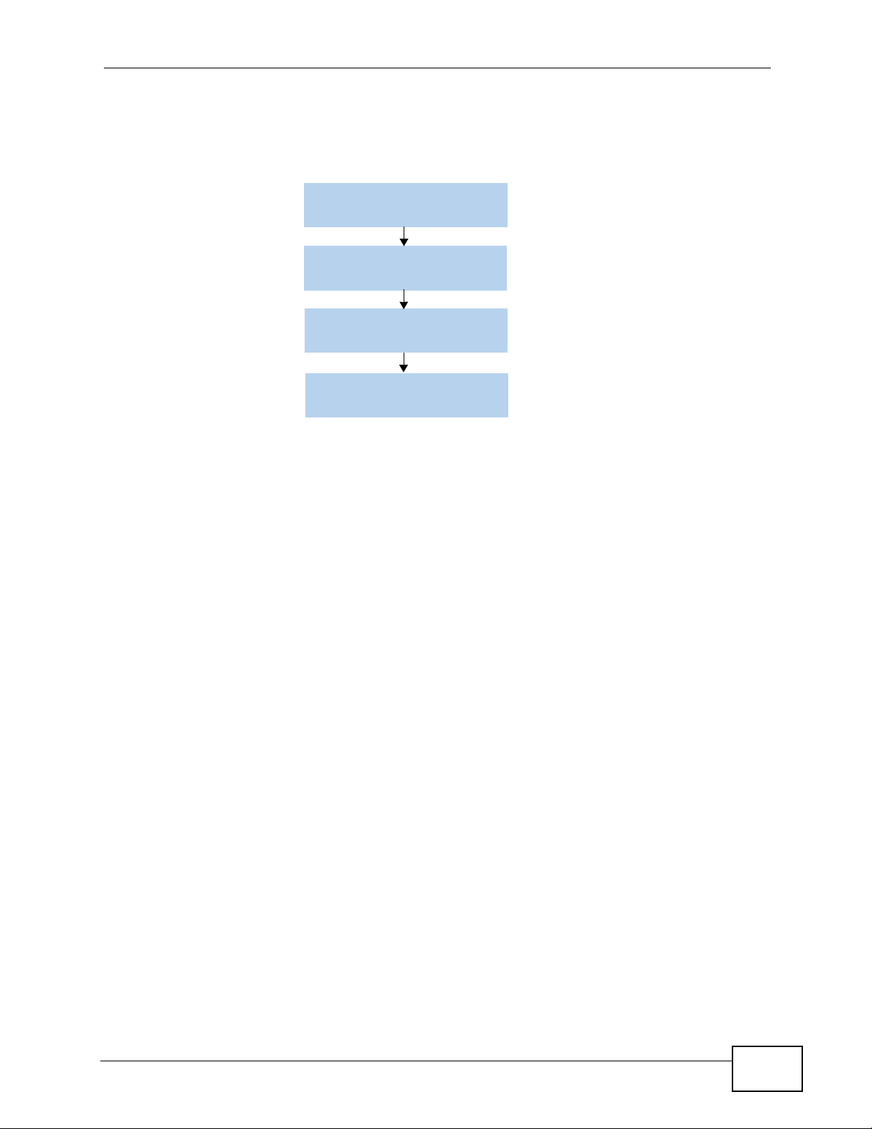
Chapter 3 Status
illustrated in the following figure, it requires several steps to complete the
initiation process.
Figure 9 Cable Network Initiation Process
Lock a DS channel
Lock an US channel
CM Auto-Provisioning
MTA Auto-Provisioning
• Search and lock a downstream channel.
• Search and lock an upstream channel.
• Auto-provisioning of the cable modem settings.
• Auto-provisioning of the MTA settings.
See Section on page 32 for more details about the provisioning process.
P-2900-4HB User’s Guide
29
Page 30
Chapter 3 Status
3.3 The System Status Screen
Click Status > System Status to open the following screen. Check these fields
when there is a problem with the network connection.
Figure 10 Status > System Status
30
The following table describes the labels in this screen.
Table 4 Status > System Status
LABEL DESCRIPTION
System Status
System Name This is the ZyXEL Device’s name. It is for identification purpose.
ZyNOS F/W
Version
WAN Information
This is the current version of the firmware the device uses. It also
shows the date the firmware was created.
P-2900-4HB User’s Guide
Page 31
Chapter 3 Status
Table 4 Status > System Status (continued)
LABEL DESCRIPTION
IP Address This is the static IP address you configured in the Advanced Setup >
Static IP screen. Normally, this is a public IP address used to
communicate with the Internet. The IP address appears as 0.0.0.0 if
you did not configure a static IP address.
IP Subnet Mask This is the subnet mask of the static IP address.
LAN Information
MAC Address This is the Media Access Control (MAC) or Ethernet address unique to
your ZyXEL De vice.
IP Address This is the LAN IP address.
IP Subnet Mask This is the subnet mask of the LAN.
DHCP This field displays the DHCP mode the ZyXEL Device is providing to
the LAN. Choices are:
Server - The ZyXEL Device is a DHCP server in the LAN. It assigns IP
addresses to DHCP clients in the LAN.
Relay - The ZyXEL Device acts as a surrogate DHCP server and r elays
DHCP requests and responses between the remote DHCP server and
the clients.
None - The ZyXEL Device is not providing any DHCP services to the
LAN.
Select this to None and turn the NAT off if you want your computers
to get DHCP IP addresses from your service provider’s DHCP server,
rather than the ZyXEL Device.
DHCP Start IP This is the first address of the contiguous addresses in the DHCP IP
address pool that the ZyXEL Device assigns to DHCP clients on your
LAN.
DHCP Pool Size This is the size or count of the DHCP IP address pool. This indicates
the number of DHCP clients that can receive IP addresses from the
ZyXEL Device.
P-2900-4HB User’s Guide
31
Page 32
Chapter 3 Status
3.4 The Cable Modem Status Screen
This section describes the information in the Cable Modem Status screen.
3.4.1 What You Need to Know About Cable Modem Status
Downstream/Upstream Channels
In order to establish a successful connection with the cable provider’s network,
the ZyXEL Device must first find and lock onto two frequencies for communication
with the cable operator’s network. A frequency is also called a channel.
Communication with the cable operator’s network cannot proceed until the ZyXEL
Device locks specific channels for sending and receiving data.
Auto-Provisioning
During the provisioning step, your ZyXEL Device passes through several
negotiation stages with the CMTS, as illustrated in the fol lowing figure. The ZyXEL
Device has to obtain an IP address, set the system’s time/date and download the
configuration file. If any step fails, the “Waiting for...” message will appear in the
CM Status screen.
Figure 11 Negotiation Stages with the CMTS
Getting an IP from
the DHCP Server
FAIL
Waiting for DHCP Offer
or
Waiting for DHCP Response
Synchronizing with
the Time Server
FAIL
Waiting for Time Server
Downloading the
Configuration File
via TFTP
FAIL
Waiting for TFTP
Operational
32
P-2900-4HB User’s Guide
Page 33

3.4.2 Viewing the Cable Modem Status Screen
Click Status > CM Status or Status > CableModem Status to open the
following screen.
Figure 12 Status > CM Status or Status > CableModem Status
Chapter 3 Status
P-2900-4HB User’s Guide
33
Page 34

Chapter 3 Status
The following table describes the labels in this screen.
Table 5 Status > CM Status or Status > CableModem Status
LABEL DESCRIPTION
Startup
Procedure
Boot State This is the provision status of the cable modem.
Configuration
File
To establish a successful connection to the cable provider’s network,
the ZyXEL Device must go through a series of well-defined initialization
steps.
• In Progress - The ZyXEL Device is in the negotiation process with
the CMTS.
• OK - The ZyXEL Device completed configuration.
• Disabled - The ZyXEL Device’s WAN connection has been disabled.
• Waiting for DHCP Offer - The ZyXEL Device is waiting for a DHCP
server to offer it an IP address.
• Waiting for DHCP Response - The ZyXEL Device is waiting for a
response from the DHCP server.
• Waiting for Time Server - The ZyXEL Device is waiting for a
response from the time server.
• Waiting for TFTP - The ZyXEL Device is waiting for a response
from the TFTP server.
• Operational - The ZyXEL Device has successfully gone through the
boot up process.
• Refused by CMTS - The ZyXEL Device could not complete one of
the initialization steps.
This is the name of the configuration file on the ZyXEL Device. This is a
binary format file which must be DOCSIS 2.0 compliant (see RFC 2132
for additional information). The field is blank if there was a problem in
obtaining or installing the configuration file.
• OK - The ZyXEL Device obtains a configuration file from the CMTS,
and installs it.
• In Progress - The ZyXEL Device is trying to obtain a configuration
file from the CMTS.
Security This shows whether an encryption method is enabled or disabled to
protect data flow over the Internet. DOCSIS uses Baseline Privacy
Interface (BPI) and BPI+ as the encryption methods.
CableModem Status
CM IP Address This is the IP address negotiated with your cable operator, after a
successful DHCP negotiation (for example, 10.21.0.11) and download
of the modem configuration file. This field may also be blanked out with
a series of dashed lines (--- --- --- ---) indicating that the modem
configuration failed or is in progress; no IP address has been set.
CM MAC
Address
Gateway IP
Address
TFTP IP Address This is the IP address of the TFTP.
Time Server IP
Address
Downstream
Channel
Information
This is the MAC address unique to your ZyXEL Device.
This is the IP address of the default gateway, if applicable.
This is the IP address of the time server.
This is the data path used by the CMTS for sending information to your
ZyXEL Device.
34
P-2900-4HB User’s Guide
Page 35

Chapter 3 Status
Table 5 Status > CM Status or Status > CableModem Status (continued)
LABEL DESCRIPTION
Lock Status This indicates whether ZyXEL Device has found a downstream channel.
The ZyXEL Device is either Locked or Not Locked on to the channel
advertised by the CMTS.
Modulation This is the method used to encode transmission information, similar to
FM or AM on your radio.
The ZyXEL Device supports 256 QAM or 64 QAM (Quadrature
Amplitude Modulation) for the downstream channel.
Downstream
Frequency
Downstream
Power
SNR The SNR (Signal to Noise Ratio), in decibels/mili-volt, is the ratio of
Upstream
Channel
Information
Lock Status This indicates whether ZyXEL Device has found an upstream channel.
Modulation This is the method used to encode transmission information, similar to
This is a standard channel frequency (in hertz) from the DOCSIS 2.0
specification.
The is the power level in decibels/mili-volt (dbmV). This value is set by
the CMTS.
signal power to channel noise power. This value is set by the CMTS.
This is the data path used by the CMTS for receiving information from
your ZyXEL Device.
The ZyXEL Device is either Locked or Not Locked on to the channel
advertised by the CMTS.
FM or AM on your radio.
The ZyXEL Device supports TDMA, ATDMA, SCDMA, Mixed or
Unknown for the upstream channel.
Channel ID This is a standard channel number from the DOCSIS 2.0 specification.
Channel numbers and channel frequencies are specified in pairs in
DOCSIS 2.0.
Symbol Rate This is the symbol rate (in Kilo symbols/second) for communication
between the CMTS and the ZyXEL Device. This is set during initial
configuration with a value supplied by the CMTS. Typical values for
QAM64 and QAM256 are 5.05 Mega-symbols/second and 5.36 Mega-
symbols/second.
Upstream
Frequency
Upstream Power The is the power level in decibels/mili-volt (dbmV). This value is set by
This is a standard channel frequency (in hertz) from the DOCSIS 2.0
specification.
the CMTS.
P-2900-4HB User’s Guide
35
Page 36
Chapter 3 Status
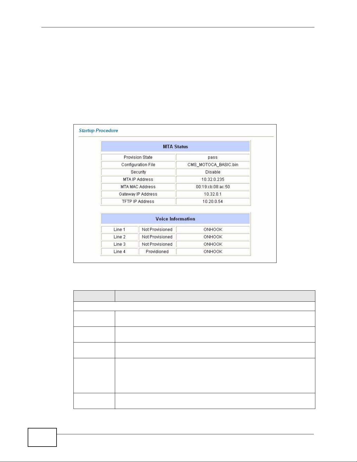
3.5 The MTA Status Screen
The Multimedia Terminal Adapter (MTA) supports conversion between analog
telephone signals and IP data packets, providing Voice over IP (VoIP) interfaces
for analog telephones.
Use the MTA Status screen to view information about the MTA. Click Status >
MTA Status to display the screen as shown.
Figure 13 Status > MTA Status
36
The following table describes the labels in this screen.
Table 6 Status > MTA Status
LABEL DESCRIPTION
MTA Status
Provision
State
Configuration
File
Security This shows whether the ZyXEL Device encrypts voice traffic (using 3DES or
MTA IP
Address
MTA MAC
Address
This is the provision state of the MTA.
This is the name of the configuration file downloaded for the MTA.
AES).
This is the IP address negotiated for the MTA, after a successful DHCP
negotiation (e.g.10.21.0.11) and download of the configuration file. This
field may also be blanked out with a series of dashed lines (--- --- --- ---)
indicating that the modem configuration failed or is in progress; no IP
address has been set.
This is the MAC address unique for the MTA.
P-2900-4HB User’s Guide
Page 37

Table 6 Status > MTA Status (continued)
LABEL DESCRIPTION
Gateway IP
Address
TFTP IP
Address
Voice Information
Line 1-4 This field shows the status information about the VoIP ports.
This is the IP address of the default gateway, if applicable.
This is the IP address of TFTP.
Chapter 3 Status
P-2900-4HB User’s Guide
37
Page 38

Chapter 3 Status
38
P-2900-4HB User’s Guide
Page 39

CHAPTER 4
Tutorials
4.1 Overview
This chapter shows you how to use the ZyXEL Device’s various features.
• Access the ZyXEL Device Using DDNS, see page 39
• Multiple WAN Configuration, see page 41
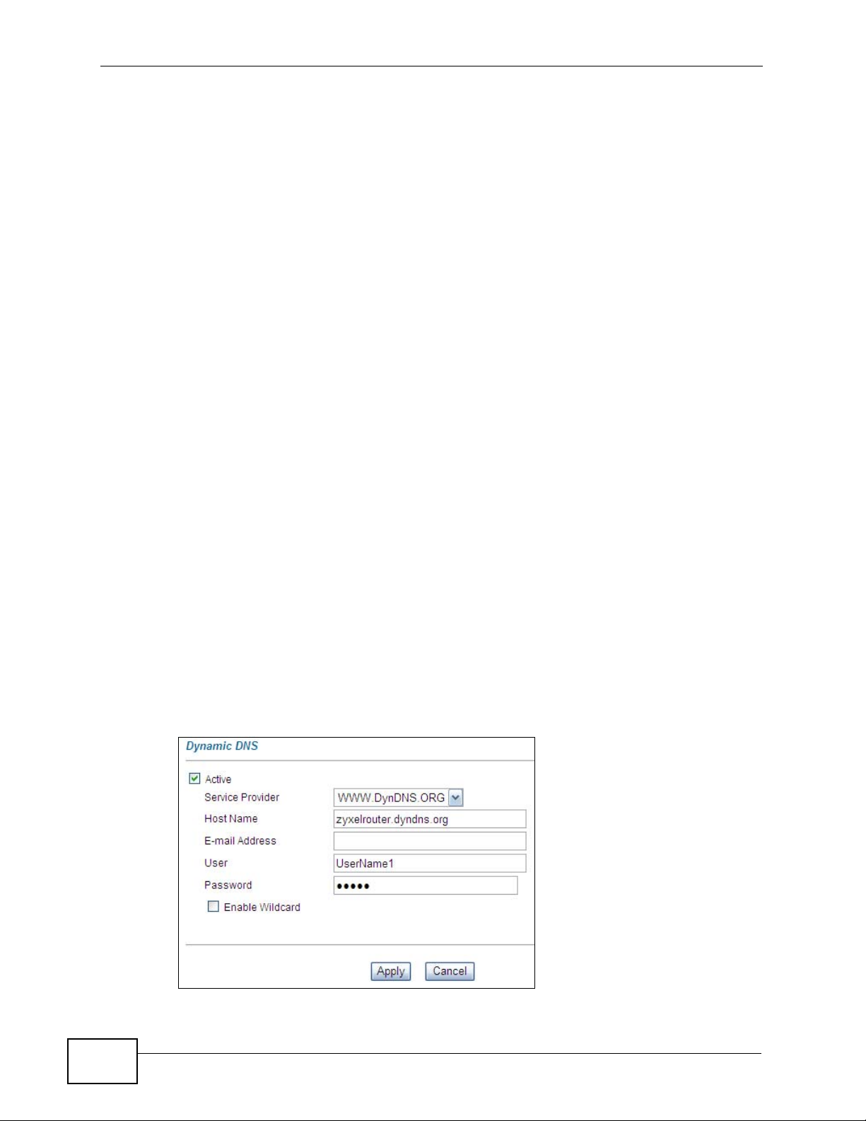
4.2 Access the ZyXEL Device Using DDNS
If you connect your ZyXEL Devi ce to the Internet and it uses a dynamic WAN IP
address, it is inconvenient for you to manage the device from the Internet. The
ZyXEL Device’s WAN IP address changes dynamically. Dynamic DNS (DDNS)
allows you to access the ZyXEL Device using a domain name.
http://zyxelrouter.dyndns.org
A
w.x.y.z
To use this feature, you have to apply for DDNS service at www.dyndns.org.
This tutorial shows you how to:
• Registering a DDNS Account on www.dyndns.org
• Configuring DDNS on Your ZyXEL Device
• Testing the DDNS Setting
Note: If you have a private WAN IP address, then you cannot use DDNS.
a.b.c.d
P-2900-4HB User’s Guide
39
Page 40
Chapter 4 Tutorials
4.2.1 Registering a DDNS Account on www.dyndns.org
1 Open a browser and type http://www.dyndns.org.
2 Apply for a user account. This tutorial uses UserName1 and 12345 as the
username and password.
3 Log into www.dyndns.org using your account.
4 Add a new DDNS host name. This tutorial uses the following settings as an
example.
• Hostname: zyxelrouter.dyndns.org
•Service Type: Host with IP address
• IP Address: Enter the WAN IP address that your ZyXEL Devi ce is currently using.
You can find the IP address on the ZyXEL Device’s Web Configurator Status
page.
Then you will need to configure the same account and host name on the ZyXEL
Device later.
4.2.2 Configuring DDNS on Your ZyXEL Device
1 Log into the ZyXEL Device's advanced mode.
2 Configure the following settings in the Advanced Setup > Dynam ic DNS screen.
2a Select Active.
2b Type zyxelrouter.dyndns.org in the Host Name field.
2c Enter the user name (UserName1) and password (12345).
40
P-2900-4HB User’s Guide
Page 41

2d Click Apply.
4.2.3 Testing the DDNS Setting
Now you should be able to access the ZyXEL Device from the Internet. To test
this:
1 Open a web browser on the computer (using the IP address a.b.c.d) that is
connected to the Internet.
2 Type http://zyxelrouter.dyndns.org and press [Enter].
3 The ZyXEL Device’s login page should appear. You can then log into the ZyXEL
Device and manage it.
4.3 Multiple WAN Configuration
Chapter 4 Tutorials
A company uses the ZyXEL Device (Z) to connect to a cable network. They apply
for three public IP addresses from the service provider (Cable SP) in order to
provide web (A) and FTP (B) services to public users and Internet access for
company users (C1 and C2). A computer from the Internet can access server A
through IP-1 and server B through IP-2. C1 and C2 connect to the ZyXEL
Device’s LAN through a switch ( S). The ZyXEL Device uses NAT t o convert private
LAN IP addresses to IP-3 for outgoing Internet packets.The following figure shows
you an example.
Figure 14 Multiple WAN Application
A
Z
Cable
SP
IP-3
C1
IP-1
B
IP-2
S
C2
P-2900-4HB User’s Guide
41
Page 42

Chapter 4 Tutorials
This tutorial uses the following example settings:
Table 7 IP Settings in this Tutorial
DEVICE / COMPUTER IP ADDRESS
Static IP 1 1.1.1.1/24
Static IP 2 2.2.2.1/24
Static IP 3 3.3.3.1/24
LAN IPs Management IP: 192.168.1.1/24
A’s IP 1.1.1.5/24 (IP-1), gateway: 1.1.1.1
B’s IP 2.2.2.5/24 (IP-2), gateway: 2.2.2.1
NAT On, Many-to-One
Note: You have to apply for a public IP address if you need one and configure it as a
DHCP Type: Server
DHCP IP Range: 192.168.1.33~192.168.1.64
static IP address on the Web Configurator.
4.3.1 Network Setup and IP Settings
Use this section to set up the network and configure the IP settings on servers A
and B. This section also shows how to enable DHCP for LAN computers IP
assignments.
1 This tutorial assumes your ZyXEL Device has successfully connected to the cable
network. You should see the ONLINE LED is on from the ZyXEL Device’s front
panel.
2 Configure the IP addresses on A and B (see Table 7). Connect them to the ZyXEL
Device’s LAN. Turn on the Web and FTP services on A and B respectively.
42
P-2900-4HB User’s Guide
Page 43

Chapter 4 Tutorials
3 Log into the ZyXEL Device’s Web Configurator. Configure the Advanced Setup >
LAN screen as shown next. Click Apply.
4 Enable DHCP client on computers C1 and C2 by selecting Obtain an IP address
automatically in the network settings. Connect th em to the ZyXEL Device’s LAN
through a switch. Each of them should get an IP address respectively.
4.3.2 Configuring Static IP Addresses
Use this section to configure two static IP addresses for servers A and B.
Computers (C1~C2) also use one static IP address to access the Internet.
P-2900-4HB User’s Guide
43
Page 44

Chapter 4 Tutorials
1 Configure the Advanced > Static IP screen as shown. Click Apply.
2 Ping A and B in the Maintenance > Diagnostic screen to test the connectivity.
You should get A’s and B’s responses. If they fail, make sure the network is
correctly connected and if each server has a firewall that they allow pi ng packets
from the ZyXEL Device. An example is shown next.
4.3.3 Configuring NAT
You must enable NAT on the ZyXEL Device if you want your LAN computers to
access the Internet using private IP addresses.
44
P-2900-4HB User’s Guide
Page 45

Chapter 4 Tutorials
1 Select Full Feature and click Apply in the Advanced Setup > NAT screen.
2 Click the Edit Details link in the NAT-Mode screen above. The NAT - Address
Mapping Rules screen appears as shown next.
3 Click the Rule 1 link.
4 Configure the settings as shown next. Then click Apply.
P-2900-4HB User’s Guide
45
Page 46

Chapter 4 Tutorials
5 Computer C1 should be able to connect to the Internet.
4.3.4 Access the Web/FTP Services from the Internet
Use a computer on the Internet to access http://1.1.1.5 and ftp://2.2.2.5. You
should be able to access a web page on A and the FTP login screen on B.
46
P-2900-4HB User’s Guide
Page 47

PART II
Advanced Setup
LAN Setup (49)
Network Address Translation (NAT)
Screens (59)
Dynamic DNS Setup (67)
Remote Management Configuration (71)
Logs (75)
47
Page 48

48
Page 49
CHAPTER 5
LAN Setup
5.1 Overview
A Local Area Network (LAN) is a shared communication system to which many
networking devices are connected. It is limited to the immediate area, usually the
same building or floor of a building.
Use the LAN screens to help you configure a LAN DHCP server and manage IP
addresses.
LAN
5.1.1 What You Can Do in the LAN Screens
•Use the LAN Setup screen (Section 5.2 on page 51) to configure the DHCP
settings, and set the LAN IP address and subnet mask of your ZyXEL Device.
You can also edit your ZyXEL Device’s RIP, Multicast and Any IP from this
screen.
•Use the Static DHCP screen (Section 5.2 on page 51) to configure the static
DHCP settings of your ZyXEL De vice.
5.1.2 What You Need To Know About LAN
IP Address
IP addresses identify individual devices on a network. Every networking device
(including computers, servers, routers, printers, etc.) needs an IP address to
communicate across the network. These networking devices are also known as
hosts.
P-2900-4HB User’s Guide
49
Page 50

Chapter 5 LAN Setup
Subnet Mask
Subnet masks determine the maximum number of possible hosts on a network.
You can also use subnet masks to divide one network into multiple sub-networks.
DHCP
A DHCP (Dynamic Host Configuration Protocol) server can assign your ZyXEL
Device an IP address, subnet mask, DNS and other routing information when it's
turned on.
RIP
RIP (Routing Information Protocol) allows a router to exchange routing
information with other routers.
Multicast
Traditionally, IP packets are transmitted in one of either two ways - Unicast (1
sender - 1 recipient) or Broadcast (1 sender - everybody on the network).
Multicast delivers IP packets to a group of hosts on the network - not everybody
and not just 1.
IGMP
IGMP (Internet Group Multicast Protocol) is a network-layer protocol used to
establish membership in a Multicast group - it is not used to carry user data.
There are two versions: 1 and 2. IGMP version 2 is an improvement over versi o n
1, but IGMP version 1 is still in wide us e.
DNS
DNS (Domain Name System) is for mapping a domain name to its corresponding
IP address and vice versa. The DNS server is extremely important because
without it, you must know the IP address of a networking device before you can
access it.
Finding Out More
See Section 5.4 on page 54 for technical background information on LANs.
5.1.3 Before You Begin
Find out the MAC addresses of your network devices if you intend to add them to
the Static DHCP screen.
50
P-2900-4HB User’s Guide
Page 51
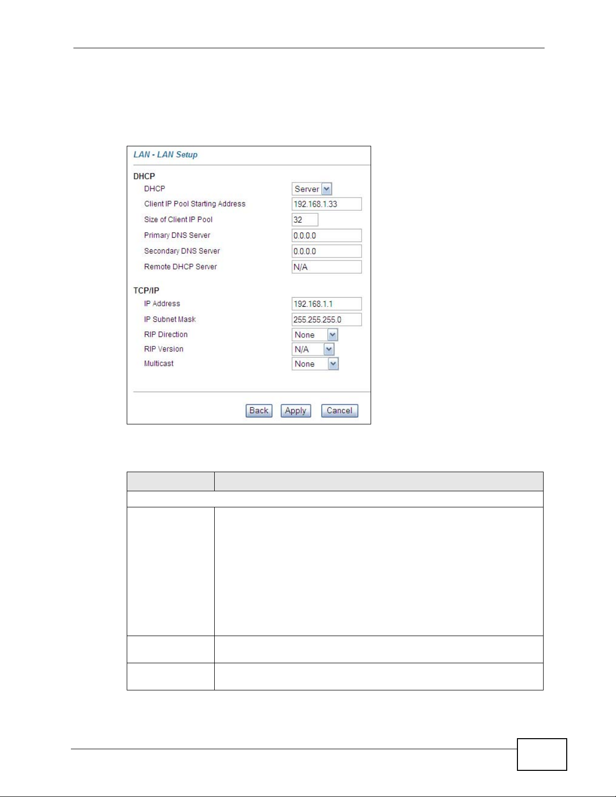
5.2 The LAN Setup Screen
Click Advanced Setup > LAN > LAN Setup to open the LAN Setup screen.
Figure 15 Advanced Setup > LAN > LAN Setup
Chapter 5 LAN Setup
The following table describes the fields in this screen.
Table 8 Advanced Setup > LAN > LAN Setup
LABEL DESCRIPTION
DHCP
DHCP If set to Server, your ZyXEL Device can assign IP addresses, an IP
default gateway and DNS servers to Windows 95, Windows NT and
other systems that support the DHCP client.
If set to None, the DHCP server will be disabled.
If set to Relay, the ZyXEL Device acts as a surrogate DHCP server and
relays DHCP requests and responses between the remote server and
the clients. Enter the IP address of the actual, remote DHCP server in
the Remote DHCP Server field in this case.
When DHCP is used, the following items need to be set.
Client IP Pool
Starting Address
Size of Client IP
Pool
This field specifies the first of the contiguous addresses in the IP
address pool.
This field specifies the size or count of the IP address pool.
P-2900-4HB User’s Guide
51
Page 52

Chapter 5 LAN Setup
Table 8 Advanced Setup > LAN > LAN Setup (continued)
LABEL DESCRIPTION
Primary DNS
Server
Secondary DNS
Server
Remote DHCP
Server
TCP/IP
IP Address Enter the IP address of your ZyXEL Device in dotted decimal notation,
IP Subnet Mask Type the subnet mask assigned to you by your ISP (if given).
RIP Direction Select the RIP direction from None, Both, In Only and Out Only. The
RIP Version Select the RIP version from RIP-1, RIP-2B and RIP-2M. The RIP
Multicast IGMP (Internet Group Multicast Protocol) is a network-layer protocol
Back Click Back to return to the previous screen without saving.
Apply Click Apply to save your changes back to the ZyXEL Device.
Cancel Click Cancel to begin configuring this screen afresh.
Enter the IP addresses of the DNS servers. The DNS servers are
passed to the DHCP clients along with the IP address and the subnet
mask.
As above.
If Relay is selected in the DHCP field above then enter the IP address
of the actual remote DHCP server here.
for example, 192.168.100.1 (factory default).
RIP Direction field controls the sending and receiving of RIP packets.
Version field controls the format and the broadcasting method of the
RIP packets that the ZyXEL Device sends (it recognizes both formats
when receiving).
used to establish membership in a multicast group. The ZyXEL Device
supports both IGMP versions 1 (IGMP-v1) and 2 (IGMP-v2). Select
None to disable it.
5.3 The Static DHCP Screen
Click Advanced Setup > LAN > Static DHCP to open the Static DHCP screen.
A DHCP server may assign a different IP address to a computer when its DHCP
52
P-2900-4HB User’s Guide
Page 53

Chapter 5 LAN Setup
lease expires. If you want the computer to always receive the same IP address
from the DHCP server, then configure a static DHCP IP address here.
Figure 16 Advanced Setup > LAN > Static DHCP
The following table describes the fields in this screen.
Table 9 Advanced Setup > LAN > Static DHCP
LABEL DESCRIPTION
# This is the index number for the entries in this table.
MAC Address Type the MAC address of the computer to which you want to assign a
specific DHCP IP address. Use hexadecimal characters in the following
format: “0A:A0:00:BB:CC:DD”
IP Address Type the IP address you want to dedicate to the computer in dotted
decimal notation, for example, “150.222.0.1”.
Back Click Back to return to the previous screen.
Apply Click Apply to save your changes back to the ZyXEL Device.
Cancel Click Cancel to begin configuring this screen afresh.
P-2900-4HB User’s Guide
53
Page 54

Chapter 5 LAN Setup
5.4 LAN Technical Reference
This section provides some technical background information about the topics
covered in this chapter.
5.4.1 DHCP Setup
DHCP (Dynamic Host Configuration Protocol, RFC 2131 and RFC 2132) allows
individual clients to obtain TCP/IP configuration at start-up from a server. You can
configure the ZyXEL Device as a DHCP server or disable it. When configured as a
server, the ZyXEL Device provides the TCP/IP configuration for the clients. If you
turn the DHCP server off, you must have another DHCP server on your LAN, or
else the computer must be manually configured.
IP Pool Setup
The ZyXEL Device is pre-configured with a pool of IP addresses for the DHCP
clients (DHCP Pool). See the product specif ic a t i o ns in the appendices. Do not
assign static IP addresses from the DHCP pool to your LAN computers.
5.4.2 DNS Server Address
There are two ways that an ISP disseminates the DNS server addresses.
• The ISP tells you the DNS server addresses, usually in the form of an
information sheet, when you sign up. If your I SP gives you the DNS server
addresses, enter them in the DNS Server fields in the LAN Setup screen.
• The ZyXEL Device acts as a DNS proxy when the Primary and Secondary DNS
Server fields are left blank in the LAN Setup screen.
5.4.3 LAN TCP/IP
The ZyXEL Device has built-in DHCP server capability that assigns IP addresses
and DNS servers to systems that support DHCP client capability.
IP Address and Subnet Mask
Where you obtain your network number depends on your particular situation. If
the ISP or your network administrator assigns you a block of registered IP
addresses, follow their instructions in selecting the IP addresses and the subnet
mask.
54
If the ISP did not explicitly give you an IP network number, then most likely you
have a single user account and the ISP will assign you a dynamic IP address when
P-2900-4HB User’s Guide
Page 55

Chapter 5 LAN Setup
the connection is established. If this were the case, it is recommended that you
select a network number from 192.168.0.0 to 192.168.255.0 and you must
enable the Network Address Translation (NAT) feature of the ZyXEL Device. The
Internet Assigned Number Authority (IANA) reserved this block of addresses
specifically for private use; please do not use any other number unless you are
told otherwise. Let's say you select 192.168.1.0 as the network number; which
covers 254 individual addresses, from 192.168.1.1 to 192.168.1.254 (zero and
255 are reserved). In other words, the first three numbers specify the network
number while the last number identifies an individual computer on that network.
Once you have decided on the network number , pick an IP address that is easy to
remember, for instance, 192.168.1.1, for your ZyXEL Device, but make sure that
no other device on your network is using that IP address.
The subnet mask specifies the network number portion of an IP address. Your
ZyXEL Device will compute the subnet mask automatically based on the IP
address that you entered. Y ou don't need to change the subnet mask computed by
the ZyXEL Device unless you are instructed to do otherwise.
Private IP Addresses
Every machine on the Internet must have a unique address. If your networks are
isolated from the Internet, for example, only between your two branch offices, you
can assign any IP addresses to the hosts without problems. However, the Internet
Assigned Numbers Authority (IANA) has reserved the following three blocks of IP
addresses specifically for private networks:
• 10.0.0.0 — 10.255.255.255
• 172.16.0.0 — 172.31.255.255
• 192.168.0.0 — 192.168.255.255
You can obtain your IP address from the IANA, from an ISP or it can be assigned
from a private network. If you belong to a small organization and your Internet
access is through an ISP, the ISP can provide you with the Internet addresses for
your local networks. On the other hand, if you are part of a much larger
organization, you should consult your network administrator for the appropriate IP
addresses.
Note: Regardless of your particular situation, do not create an arbitrary IP address;
always follow the guidelines above. For more information on address
assignment, please refer to RFC 1597, Address Allocation for Private Internets
and RFC 1466, Guidelines for Management of IP Address Space.
P-2900-4HB User’s Guide
55
Page 56

Chapter 5 LAN Setup
5.4.4 RIP Setup
RIP Directions
The sending and receiving of RIP packets can occur in the following ways:
•Both - the ZyXEL Device will broadcast its routing table periodically and
incorporate the RIP information that it receives.
•In Only - the ZyXEL Device will not send any RIP packets but will accept all RIP
packets received.
•Out Only - the ZyXEL Device will send out RIP packets but will not accept any
RIP packets received.
•None - the ZyXEL Device will not send any RIP packets and will ignore any RIP
packets received.
RIP Versions
RIP-1 is universally supported, but RIP-2 carries more information. RIP-1 is
probably adequate for most networks, unless you have an unusual network
topology.
Both RIP-2B and RIP-2M sends the routing data in RIP-2 format; the difference
being that RIP-2B uses subnet broadcasting while RIP-2M uses multicasting.
5.4.5 Multicast
Traditionally, IP packets are transmitted in one of either two ways - Unicast (1
sender - 1 recipient) or Broadcast (1 sender - everybody on the network).
Multicast delivers IP packets to a group of hosts on the network - not everybody
and not just 1.
IGMP (Internet Group Multicast Protocol) is a network-layer protocol used to
establish membership in a Multicast group - it is not used to carry user data. IGMP
version 2 (RFC 2236) is an improvement over version 1 (RFC 1112) but IGMP
version 1 is still in wide use. If you would like to read more detailed information
about interoperability between IGMP version 2 and version 1, please see sections
4 and 5 of RFC 2236. The class D IP address is used to identify host groups and
can be in the range 224.0.0.0 to 239.255.255.255. The address 224.0.0.0 is not
assigned to any group and is used by IP multicast computers. The address
224.0.0.1 is used for query messages and is assigned to the permanent group of
all IP hosts (including gateways). All host s must join t he 224.0.0.1 group in order
to participate in IGMP. The address 224.0.0.2 is assigned to the multicast routers
group.
56
The ZyXEL Device supports both IGMP version 1 (IGMP-v1) and IGMP version 2
(IGMP-v2). At start up, the ZyXEL Device q ueries all directly connected networks
P-2900-4HB User’s Guide
Page 57

Chapter 5 LAN Setup
to gather group membership. After that, the Z yXEL Device periodically updates
this information. IP multicasting can be enabled/disabled on the ZyXEL Device LAN
and/or WAN interfaces in the web configurator (LAN; WAN). Select None to
disable IP multicasting on these interfaces.
P-2900-4HB User’s Guide
57
Page 58

Chapter 5 LAN Setup
58
P-2900-4HB User’s Guide
Page 59

CHAPTER 6
Network Address Translation
(NAT) Screens
6.1 Overview
This chapter discusses how to configure NAT on the ZyXEL Device. NAT (Network
Address Translation - NAT, RFC 1631) is the translation of the IP address of a host
in a packet, for example, the source address of an outgoing packet, used within
one network to a different IP address known within another network.
6.1.1 What You Can Do in the NAT Screen
Use the NAT Mode screen (Section 6.2 on page 60) to disable NA T, or enable and
configure NAT mapping rules.
6.1.2 What You Need to Know About NAT
Inside/Outside
Inside/outside denotes where a host is located relative to the ZyXEL Device, for
example, the computers of your subscribers are the inside hosts, while the web
servers on the Internet are the outside hosts.
Global/Local
Global/local denotes the IP address of a host in a packet as the packet tr av erses a
router, for example, the local address refers to the IP address of a host when the
packet is in the local network, while the global address refers to the IP address of
the host when the same packet is traveling in the WAN side.
NAT
In the simplest form, NA T changes the source IP address in a pack et received from
a subscriber (the inside local address) to another (the inside global address)
before forwarding the packet to the WAN side. When the response comes back,
P-2900-4HB User’s Guide
59
Page 60

Chapter 6 Network Address Translation (NAT ) Scr ee ns
NAT translates the destination address (the inside global address) back to the
inside local address before forwarding it to the original inside host.
Finding Out More
See Section 6.3 on page 63 for technical background information on NAT.
6.2 The NAT Mode Screen
You must create a firewall rule in addition to setting up NAT, to allow traffic from
the WAN to be forwarded through the ZyXEL Device. Click Advanced Setup >
NAT to open the following screen.
Figure 17 Advanced Setup > NAT
The following table describes the labels in this screen.
Table 10 Advanced Setup > NAT
LABEL DESCRIPTION
None Select this to disable NAT.
Full Feature Select this to enable NAT.
Edit Details Click this link to take you to a screen where you can configure public and
private IP mapping rules.
Apply Click Apply to save your configuration.
6.2.1 Configuring Address Mapping Rules
Ordering your rules is important because the ZyXEL Device applies the rules in the
order that you specify. When a rule matches the current packet, the ZyXEL Device
takes the corresponding action and the remaining rules are ignored. If there are
any empty rules before your new configured rule, your configured rule will be
pushed up by that number of empty rules. For example, if you have already
configured rules 1 to 6 in your current set and now you configure rule number 9.
In the set summary screen, the new rule will be rule 7, not 9. Now if you delete
60
P-2900-4HB User’s Guide
Page 61

Chapter 6 Network Address Translation (NAT) Screens
rule 4, rules 5 to 7 will be pushed up by 1 rule, so old rules 5, 6 and 7 become new
rules 4, 5 and 6.
Click Advanced Setup > NAT, select Full Feature and click Edit Details to open
the following screen. Use this screen to change your ZyXEL Device’ s address
mapping settings.
Figure 18 Address Mapping Rules
The following table describes the fields in this screen.
Table 11 Address Mapping Rules
LABEL DESCRIPTION
Local Start IP This is the starting Inside Local IP Address (ILA). Local IP addresses are
N/A for Server port mapping.
Local End IP This is the end Inside Local IP Address (ILA). If the rule is for all local IP
addresses, then this field displays 0.0.0.0 as the Local Start IP address
and 255.255.255.255 as the Local End IP address. This field is N/A for
One-to-one and Server mapping types.
Global Start IPThis is the starting Inside Global IP Address (IGA). Enter 0.0.0.0 here if
you have a dynamic IP address from your ISP. You can only do this for
Many-to-One and Server mapping types.
Global End IP This is the ending Inside Global IP Address (IGA). This field is N/A for
One-to-one, Many-to-One and Server mapping types.
Type 1-1: One-to-one mode maps one local IP address to one global IP
address. Note that port numbers do not change for the One-to-one NAT
mapping type.
M-1: Many-to-One mode maps multiple local IP addresses to one global
IP address.
Server: This type allows you to specify inside servers of different
services behind the NAT to be accessible to the outside world.
Back Click Back to return to the NAT Mode screen.
P-2900-4HB User’s Guide
61
Page 62
Chapter 6 Network Address Translation (NAT ) Scr ee ns
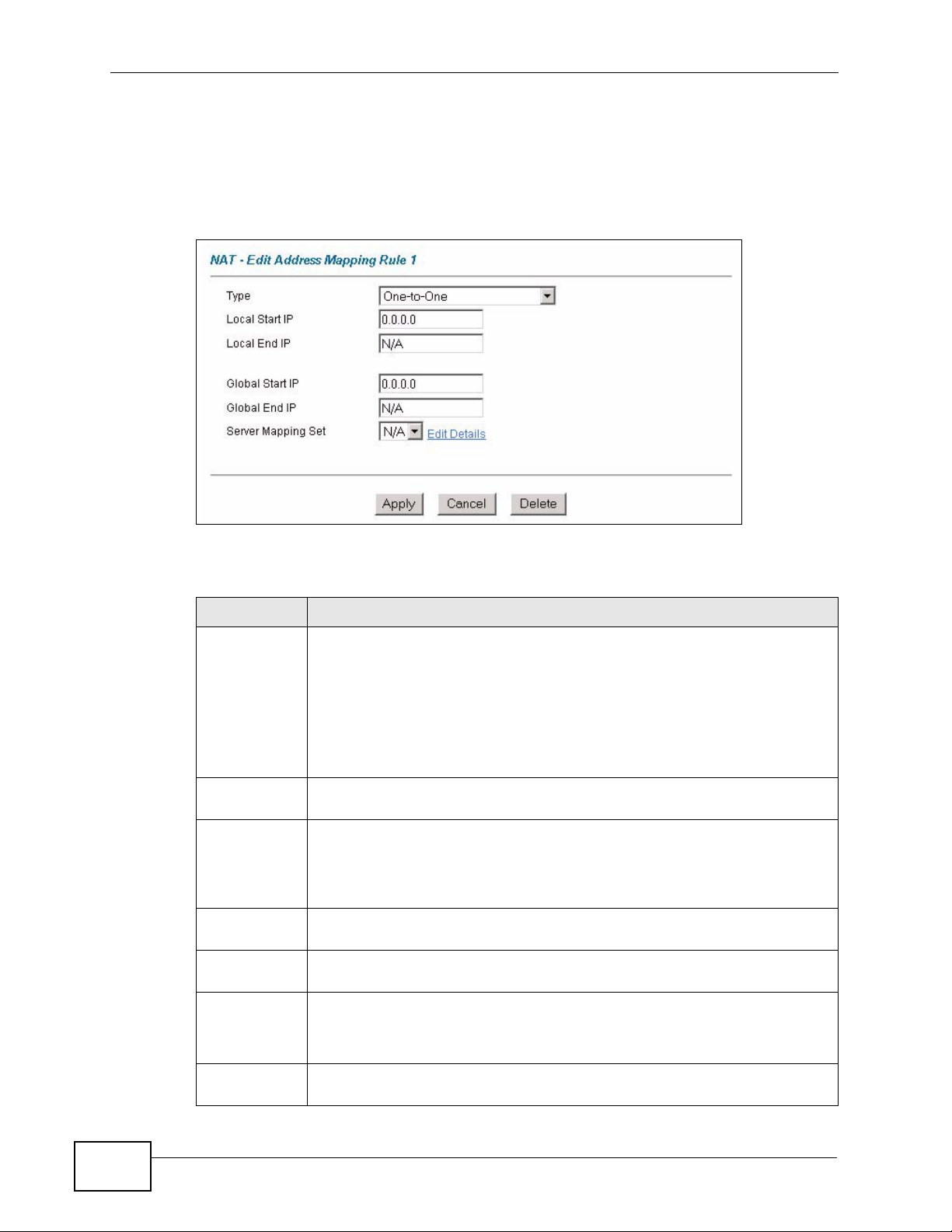
6.2.2 Editing an Address Mapping Rule
Use this screen to edit an address mapping rule. Click the rule’s link in the NAT
Address Mapping Rules screen to display the screen shown next.
Figure 19 Edit Address Mapping Rule
The following table describes the fields in this screen.
Table 12 Edit Address Mapping Rule
LABEL DESCRIPTION
Type Choose the port mapping type from one of the following.
• One-to-One: One-to-One mode maps one local IP address to one
global IP address. Note that port numbers do not change for One-toone NAT mapping type.
• Many-to-One: Many-to-One mode maps multiple local IP addresses
to one global IP address.
• Server: This type allows you to specify inside servers of different
services behind the NAT to be accessible to the outside world.
Local Start IP This is the starting local IP address (ILA). Local IP addresses are N/A for
Server port mapping.
Local End IP This is the end local IP address (ILA). If your rule is for all local IP
addresses, then enter 0.0.0.0 as the Local Start IP address and
255.255.255.255 as the Local End IP address.
This field is N/A for One-to-One and Server mapping types.
Global Start IPThis is the starting global IP address (IGA). Enter 0.0.0.0 here if you have
a dynamic IP address from your ISP.
Global End IP This is the ending global IP address (IGA). This field is N/A for One-to-
One, Many-to-One and Server mapping types.
Server
Mapping Set
Edit Details Click this link to go to the NAT - Edit NAT Server Set screen to edit a
Only available when Type is set to Server.
Select a number from the drop-down menu to choose a server set from
the NAT - Address Mapping Rules screen.
server set that you have selected in the Server Mapping Set field.
62
P-2900-4HB User’s Guide
Page 63

Chapter 6 Network Address Translation (NAT) Screens
Table 12 Edit Address Mapping Rule (continued)
LABEL DESCRIPTION
Apply Click Apply to save your changes back to the ZyXEL Device.
Cancel Click Cancel to return to the previously saved settings.
Delete Click Delete to exit this screen without saving.
6.3 NAT Technical Reference
This section provides some technical background information about the topics
covered in this chapter.
6.3.1 NAT Definitions
Inside/outside denotes where a host is located relative to the ZyXEL Device, for
example, the computers of your subscribers are the inside hosts, while the web
servers on the Internet are the outside hosts.
Global/local denotes the IP address of a host in a packet as the packet tr av erses a
router, for example, the local address refers to the IP address of a host when the
packet is in the local network, while the global address refers to the IP address of
the host when the same packet is traveling in the WAN side.
Note that inside/outside refers to the location of a host, while global/local refers to
the IP address of a host used in a packet. Thus, an inside local address (ILA) is the
IP address of an inside host in a packet when the packet is still in the local
network, while an inside global address (IGA) is the IP address of the same inside
host when the packet is on the WAN side. The following table summarizes this
information.
Table 13 NAT Definitions
ITEM DESCRIPTION
Inside This refers to the host on the LAN.
Outside This refers to the host on the WAN.
Local This refers to the packet address (source or destination) as the packet travels
on the LAN.
Global This refers to the packet address (source or destination) as the packet travels
on the WAN.
NAT never changes the IP address (either local or global) of an outside host.
P-2900-4HB User’s Guide
63
Page 64
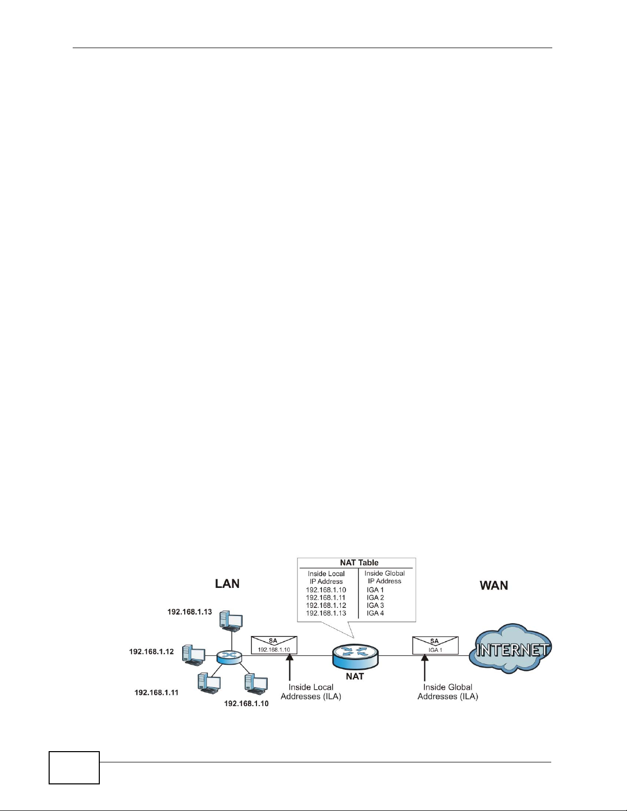
Chapter 6 Network Address Translation (NAT ) Scr ee ns
6.3.2 What NAT Does
In the simplest form, NA T changes the source IP address in a pack et received from
a subscriber (the inside local address) to another (the inside global address)
before forwarding the packet to the WAN side. When the response comes back,
NAT translates the destination address (the inside global address) back to the
inside local address before forwarding it to the original inside host. Note that the
IP address (either local or global) of an outside host is never changed.
The global IP addresses for the inside hosts can be either static or dynamically
assigned by the ISP. In addition, you can designate servers, for example, a web
server and a telnet server, on your local network and make them accessibl e to the
outside world. If you do not define any servers (for Man y-to-One – see Table 14 on
page 65), NAT offers the ad ditional benefit of firewall protection. With no servers
defined, your ZyXEL Device filters out all incoming inquiries, thus preventing
intruders from probing your network. For more information on IP address
translation, refer to RFC 1631, The IP Network Address Translator (NAT).
6.3.3 How NAT Works
Each packet has two addresses – a source address and a destination address. For
outgoing packets, the ILA (Inside Local Address) i s the source address on the LAN,
and the IGA (Inside Global Address) is the source address on the WAN. For
incoming packets, the ILA is the destination address on the LAN, and the IGA is
the destination address on the WAN. NAT maps private (local) IP addresses to
globally unique ones required for communication with hosts on other networks. It
replaces the original IP source address (and TCP or UDP source port numbers for
Many-to-One in each packet and then forwards it to the Internet. The ZyXEL
Device keeps track of the original addresses and port numbers so incoming reply
packets can have their original values restored. The following figure illustrates
this.
Figure 20 How NAT Works
64
P-2900-4HB User’s Guide
Page 65

6.3.4 NAT Mapping Types
NAT supports five types of IP/port mapping. They are:
• One to One: In One-to-One mode, the ZyXEL Device maps one local IP address
to one global IP address.
• Many to One: In Many-to-One mode, the ZyXEL Device maps multiple local IP
addresses to one global IP address.
• Server: This type allows you to specify inside servers of different services
behind the NAT to be accessible to the outside world.
Port numbers do NOT change for One-to-One NAT mapping type.
The following table summarizes these types.
Table 14 NAT Mapping Types
TYPE IP MAPPING
One-to-One ILA1ÅÆ IGA1
Many-to-One ILA1ÅÆ IGA1
Chapter 6 Network Address Translation (NAT) Screens
ILA2ÅÆ IGA1
…
Server Server 1 IPÅÆ IGA1
Server 2 IPÅÆ IGA1
Server 3 IPÅÆ IGA1
P-2900-4HB User’s Guide
65
Page 66

Chapter 6 Network Address Translation (NAT ) Scr ee ns
66
P-2900-4HB User’s Guide
Page 67

CHAPTER 7
Dynamic DNS Setup
7.1 Overview
Dynamic DNS allows you to update your current dynamic IP address with one or
many dynamic DNS services so that anyone can contact you (in NetMeeting, CUSeeMe, etc.). You can also access your FTP server or Web site on your own
computer using a domain name (for instance myhost.dhs.org, where myhost is a
name of your choice) that will never change instead of using an IP address that
changes each time you reconnect. Your friends or relatives will always be able to
call you even if they don't know your IP address.
First of all, you need to have registered a dynamic DNS account with
www.dyndns.org. This is for people with a dynamic IP from their ISP or DHCP
server that would still like to have a domain name. The Dynamic DNS service
provider will give you a password or key.
7.1.1 What You Can Do in the Dynamic DNS Screen
Use the Dynamic DNS screen (Section 7.2 on page 68) to enable DDNS and
configure the DDNS settings on the ZyXEL Device.
7.1.2 What You Need to Know About Dynamic DNS
DYNDNS Wildcard
Enabling the wildcard feature for your host causes *.yourhost.dyndns.org to be
aliased to the same IP address as yourhost.dyndns.org. This feature is useful if
you want to be able to use, for example, www.yourhost.dyndns. org and still reach
your hostname.
If you have a pri vat e WAN IP address, then you cannot use Dynamic DNS.
P-2900-4HB User’s Guide
67
Page 68

Chapter 7 Dynamic DNS Setup
7.2 The Dynamic DNS Screen
To change your ZyXEL Device’s DDNS, click Advanced Setup > Dynamic DNS.
The screen appears as shown.
Figure 21 Advanced Setup > Dynamic DNS
The following table describes the fields in this screen.
Table 15 Advanced Setup > Dynamic DNS
LABEL DESCRIPTION
Active Select this check box to use dynamic DNS.
Service
Provider
Host Names Type the domain name assigned to you r ZyXEL Device by your Dynamic
E-mail Address Type your e-mail address.
User Type your user name.
Password Type the password assigned to you.
Enable
Wildcard
Apply Click Apply to save your changes back to the ZyXEL Device.
Cancel Click Cancel to begin configuring this screen afresh.
This is the name of your Dynamic DNS service provider.
DNS provider.
Select the check box to enable DYNDNS Wildcard.
68
P-2900-4HB User’s Guide
Page 69
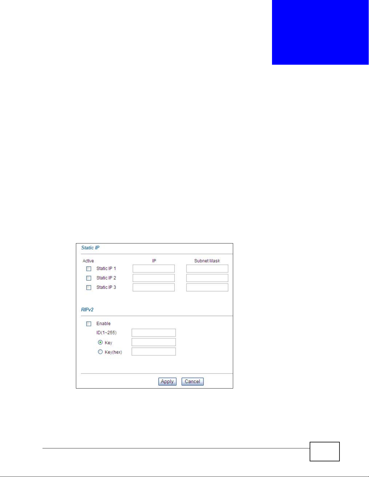
CHAPTER 8
Static IP
8.1 Overview
Use the Static IP screen (see Section 8.2 on page 69) to assign static IP
addresses and configure the RIPv2 settings. See the Section 4. 3 on page 41 for an
application example of how you can use static IP addresses.
8.2 The Static IP Screen
Click Advanced Setup > Static IP to open the following screen. Use this screen
to configure the static WAN IP addresses.
Figure 22 Advanced Setup > Static IP
P-2900-4HB User’s Guide
69
Page 70

Chapter 8 Static IP
The following table describes the fields in this screen.
Table 16 Advanced Setup > Static IP
LABEL DESCRIPTION
Static IP
Active Static IP
1-3
IP Enter the IP address in this field.
Subnet Mask Enter the subnet mask in this field.
RIPv2
Enable Select this to activate RIP.
ID (1-255) Enter the ID number obtained from the router you want to exchange
Key Enter the key obtained from the router you want to exchange
Key (hex) Enter the key obtained from the router you want to exchange
Apply Click Apply to save your changes.
Cancel Click Cancel to begin configuring this screen afresh.
Select this to activate the static IP feature.
information.
information.
information.
70
P-2900-4HB User’s Guide
Page 71
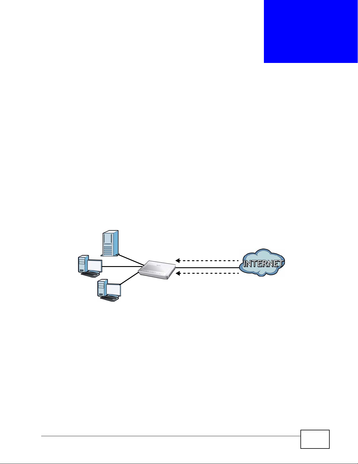
CHAPTER 9
Remote Management
Configuration
9.1 Overview
Remote management allows you to determine which s ervices/protocols can access
which ZyXEL Device interface (if any) from which computers.
The following figure shows remote management of the ZyXEL Device coming in
from the WAN.
Figure 23 Remote Management From the WAN
LAN
Note: When you configure remote management to allow management from the WAN,
you still need to configure a firewall rule to allow access.
You may manage your ZyXEL Device from a remote location via:
•Internet (WAN only)
•ALL (LAN and WAN)
•LAN only,
• Neither (Disable).
WAN
HTTP
Telnet
To disable remote management of a service, select Disable in the corresponding
Access Status field.
P-2900-4HB User’s Guide
71
Page 72

Chapter 9 Remote Management Configuration
You ma y only have one remote management session running at a time. The ZyXEL
Device automatically disconnects a remote management session of lower priority
when another remote management session of higher priority starts. The priorities
for the different types of remote management sessions are as follows.
1 Telnet
2 HTTP
Finding Out More
See Section 9.3 on page 74 for technical background information on remote
management configuration.
9.1.1 What You Can Do in the Remote Management Screen
Use the Remote Management screen (Section 9.2 on page 72) to configure
through which interface and from which IP address users can use Telnet, FTP or
HTTP to manage the ZyXEL Device.
9.2 The Remote Management Screen
Click Advanced Setup > Remote Management to open the following screen.
Figure 24 Advanced Setup > Remote Management
72
P-2900-4HB User’s Guide
Page 73
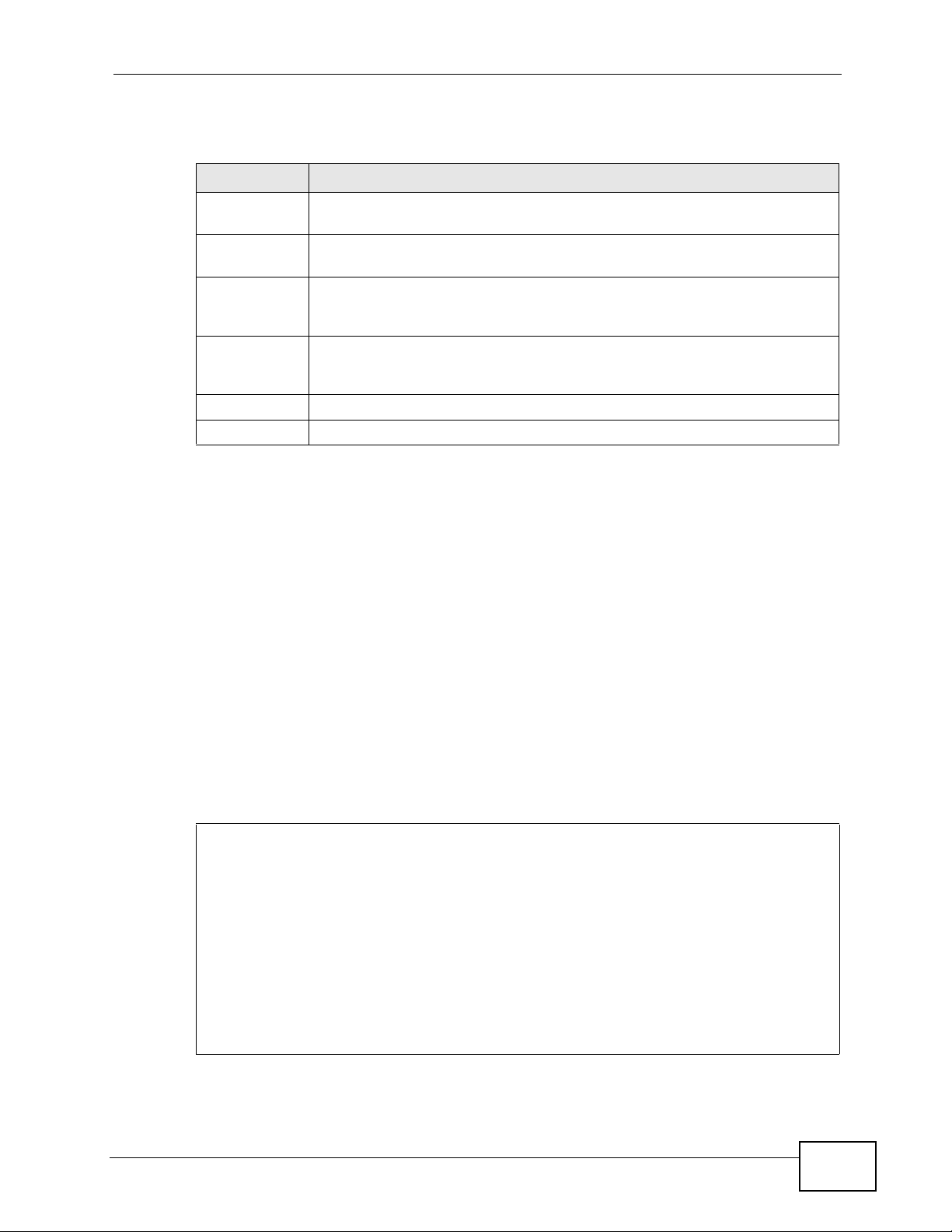
Chapter 9 Remote Management Configuration
The following table describes the fields in this screen.
Table 17 Advanced Setup > Remote Management
LABEL DESCRIPTION
Server Type Each of these labels denotes a service that you may use to remotely
manage the ZyXEL Device.
Access Status Select the access interface. Choices are All, LAN Only, WAN Only and
Disable.
Port This field shows the port number for the remote management service.
You ma y change the port number for a service in this field, but you must
use the same port number to use that service for remote management.
Secured
Client IP
Apply Click Apply to save your settings back to the ZyXEL Device.
Cancel Click Cancel to begin configuring this screen afresh.
The default 0.0.0.0 allows any client to use this service to remotely
manage the ZyXEL Device. Type an IP address to restrict access to a
client with a matching IP address.
Note: You can upload and download the ZyXEL Device configuration files using FTP.
To use this feature, your computer must have an FTP client.
Note: You can use the ZyXEL Device’s embedded web configurator for configuration
and file management.
9.2.1 Firmware Upgrade Example
The OS (Operating System) firmw are (sometimes referred to as the “ras” file) has
a “bin” filename extension. This example shows how to access the ZyXEL Device
from LAN using FTP, type the user name and password and then use the put
xxx.bin ras command to replace the current firmware (named ras) with the
firmware file firmware.bin. Wait until the uploading is completed, type quit to
exit FTP.
Figure 25 FTP Firmware Upgrade Example
D:\Firmware\P-29004HB>ftp 192.168.1.1
Connected to 192.168.1.1.
220 P2900 FTP version 1.0 ready at Mon Jan 03 08:08:45 2000
User (192.168.1.1:(none)): admin
331 Enter PASS command
Password:
230 Logged in
ftp> put
200 Port command okay
150 Opening data connection for STOR ras
226 File received OK
ftp: 3648378 bytes sent in 140.79Seconds 25.91Kbytes/sec.
ftp> quit
firmware.bin ras
P-2900-4HB User’s Guide
73
Page 74

Chapter 9 Remote Management Configuration
9.3 Remote Management Technical Reference
This section provides some technical background information about the topics
covered in this chapter.
9.3.1 Remote Management Limitations
Remote management does not work when:
• You have not enabled that service on the interface in the corresponding remote
management screen.
• You have disabled that service in one of the remote management screens.
• The IP address in the Secured Client IP field does not match the client IP
address. If it does not match, the ZyXEL Device will disconnect the session
immediately.
• There is already another remote management session with an equal or higher
priority running. You may only have one remote management session running
at one time.
9.3.2 Remote Management and NAT
When NAT is enabled:
• Use the ZyXEL Device’s WAN IP address when configuring from the WAN.
• Use the ZyXEL Device’s LAN IP address when configuring from the LAN.
9.3.3 System Timeout
There is a default system management idle timeout of five minutes (three
hundred seconds). The ZyXEL Device automatically logs you out if the
management session remains idle for longer than this timeout period. The
management session does not time out when a statistics screen is polling.
74
P-2900-4HB User’s Guide
Page 75

CHAPTER 10
Logs
10.1 Overview
This chapter contains information about configuring general log settings and
viewing the ZyXEL Device’s logs. Refer to the appendix for example log message
explanations.
The web configurator allows you to choose which categories of events and/or
alerts to have the ZyXEL Device log and then display the logs or have the ZyXEL
Device send them to an administrator (as e-mail) or to a syslog server.
10.1.1 What You Can Do in the Log Screens
•Use the Log Settings screen (Section 10.2 on page 76) to configure the mail
server, the syslog server, when to send logs, and what logs to send.
•Use the View Logs screen (Section 10.3 on page 78) to see the logs for the
categories that you selected in the Log Settings screen.
10.1.2 What You Need to Know About Logs
Alerts
An alert is a message that is enabled as soon as the event occurs. They include
system errors, attacks (access control) and attempted access to blocked web
sites. Some categories such as System Errors consist of both logs and alerts. Y ou
may differentiate them by their color in the View Log screen. Alerts display in red
and logs display in black.
Logs
A log is a message about an event that occurred on your ZyXEL Device. For
example, when someone logs in to the ZyXEL Device, you can set a schedule for
how often logs should be enabled, or sent to a syslog server.
P-2900-4HB User’s Guide
75
Page 76

Chapter 10 Logs
10.2 The Log Settings Screen
Use the Log Settings screen to configure to where the ZyXEL Device is to send
logs; the schedule for when the ZyXEL Device is to send the logs and which logs
and/or immediate alerts the ZyXEL Device is to record.
T o change your Z yXEL Device’s l og settings, click Advanced Setup > Logs > Log
Settings to open the following screen.
Alerts are e-mailed as soon as they happen. Logs may be e-mailed as soon as the
log is full. Selecting many alert and/or log categories ( especially Access Control)
may result in many e-mails being sent.
Figure 26 Advanced Setup > Logs > Log Settings
76
P-2900-4HB User’s Guide
Page 77

Chapter 10 Logs
The following table describes the fields in this screen.
Table 18 Advanced Setup > Logs > Log Settings
LABEL DESCRIPTION
Address Info
Mail Server Enter the server name or the IP address of the mail server for the e-mail
addresses specified below. If this field is left blank, logs and alert
messages will not be sent via e-mail.
Mail Subject Type a title that you want to be in the subject line of the log e-mail
message that the ZyXEL Device sends.
Send log to Logs are sent to the e-mail address specified in this field. If this field is
left blank, logs will not be sent via e-mail.
Send alerts to Alerts are sent to the e-mail address specified in this field. If this field is
left blank, alerts will not be sent via e-mail.
UNIX Syslog Syslog logging sends a log to an external syslog server used to store
logs.
Active Click Active to enable syslog logging.
Syslog IP
Address
Log Facility Select a location from the drop down list box. The log facility allows you
Send Log
Log Schedule This drop-down menu is used to configure the frequency of log messages
Enter the server name or IP address of the syslog server that will log the
selected categories of logs.
to log the messages to different files in the syslog server. Refer to the
documentation of your syslog program for more details.
being sent as E-mail:
• Daily
• Weekly
•Hourly
• When Log is Full
•None.
If you select Weekly or Daily, specify a time of day when the E-mail
should be sent. If you select Weekly, then also specify which day of the
week the E-mail should be sent. If you select When Log is Full, an alert
is sent when the log fills up. If you select None, no log messages are
sent
Day for
Sending Log
Time for
Sending Log
Log Select the categories of logs that you want to record. Logs include alerts.
Send
Immediate
Alert
Back Click Back to return to the previous screen.
Apply Click Apply to save your customized settings and exit this screen.
Cancel Click Cancel to return to the previously saved settings.
Use the drop down list box to select which day of the week to send the
logs.
Enter the time of the day in 24-hour format (for example 23:00 equals
11:00 pm) to send the logs.
Select the categories of alerts for which you want the ZyXEL Device to
instantly e-mail alerts to the e-mail address specified in the Send Alerts
To field.
P-2900-4HB User’s Guide
77
Page 78

Chapter 10 Logs
10.3 The View Logs Screen
Click Advanced Setup > Logs > View Logs to open the screen. Use the View
Logs screen to see the logs for the categories that you selected in the Log
Settings screen (see Section 10.2 on page 76).
Entries in red indicate alerts. The log wraps around and deletes the old entries
after it fills. Click a column heading to sort the entries. A triangle indicates
ascending or descending sort order.
Figure 27 Advanced Setup > Logs > View Logs
The following table describes the fields in this screen.
Table 19 Advanced Setup > Logs > View Logs
LABEL DESCRIPTION
Display The categories that you select in the Log Settings screen display in the
drop-down list box.
Select a category of logs to view; select All Logs to view logs from all of
the log categories that you selected in the Log Settings page.
Time This field displays the time the log was recorded.
Message This field states the reason for the log.
Source This field lists the source IP address and the port number of the incoming
packet.
Destination This field lists the destination IP address and the port number of the
incoming packet.
Notes This field displays additional information about the log entry.
Back Click Back to return to the previous screen
Email Log
Now
Refresh Click Refresh to renew the log screen.
Clear Log Click Clear Log to delete all the logs.
Click Email Log Now to send the log screen to the e-mail address
specified in the Log Settings page (make sure that you have first filled
in the Address Info fields in Log Settings).
10.3.1 Email Log Example
An "End of Log" message displays for each mail in which a complete log has been
sent. The following is an example of a log sent by e-mail.
78
P-2900-4HB User’s Guide
Page 79

Chapter 10 Logs
• You may edit the subject title.
• "End of Log" message shows that a complete log has been sent.
Figure 28 E-mail Log Example
Subject:
Firewall Alert From ZyXEL Device
Date:
Fri, 07 Apr 2000 10:05:42
From:
user@zyxel.com
To:
user@zyxel.com
1|Apr 7 00 |From:192.168.1.1 To:192.168.1.255 |default policy |forward
| 09:54:03 |UDP src port:00520 dest port:00520 |<1,00> |
2|Apr 7 00 |From:192.168.1.131 To:192.168.1.255 |default policy |forward
| 09:54:17 |UDP src port:00520 dest port:00520 |<1,00> |
3|Apr 7 00 |From:192.168.1.6 To:10.10.10.10 |match |forward
| 09:54:19 |UDP src port:03516 dest port:00053 |<1,01> |
……………………………..{snip}…………………………………..
……………………………..{snip}…………………………………..
126|Apr 7 00 |From:192.168.1.1 To:192.168.1.255 |match |forward
| 10:05:00 |UDP src port:00520 dest port:00520 |<1,02> |
127|Apr 7 00 |From:192.168.1.131 To:192.168.1.255 |match |forward
| 10:05:17 |UDP src port:00520 dest port:00520 |<1,02> |
128|Apr 7 00 |From:192.168.1.1 To:192.168.1.255 |match |forward
| 10:05:30 |UDP src port:00520 dest port:00520 |<1,02> |
End of Firewall Log
Time Format
Month-Day-Year
Time Format
Day-Month-Year
P-2900-4HB User’s Guide
79
Page 80

Chapter 10 Logs
80
P-2900-4HB User’s Guide
Page 81

PART III
Maintenance and
Troubleshooting
Maintenance (83)
Troubleshooting (89)
81
Page 82

82
Page 83

CHAPTER 11
Maintenance
11.1 Overview
This chapter discusses how to view the DHCP client and system information.
11.2 What You Can Do in this Chapter
•Use the DHCP Table screen (Section 11.3 on page 83) to show current DHCP
Client information (including IP Address, Host Name and MAC Address) of
all network clients using the DHCP server.
•Use the Diagnostic screens (Section 11.4 on page 85) to display information to
help you identify problems with the ZyXEL Device.
11.3 The DHCP Table Screen
DHCP (Dynamic Host Configuration Protocol, RFC 2131 and RFC 2132) allows
computers to obtain IP addresses, subnet masks, and other TCP/IP settings at
start-up from a server. You can configure the ZyXEL Device as a DHCP server or
disable it (See Section 5.2 on page 51). When configured as a server, the ZyXEL
Device provides the TCP/IP configuration for the clients. If set to None, DHCP
service will be disabled and you must have another DHCP server on your LAN, or
else the computer must be manually configured. The DHCP table shows what
network computers, identified by their IP address and host name, obtained what
IP addresses.
Click Maintenance, and then the DHCP Table tab. Read-only information here
relates to your DHCP status. The DHCP table shows current DHCP Client
P-2900-4HB User’s Guide
83
Page 84
Chapter 11 Maintenance
information (including IP Address, Host Name and MAC Address) of all
network computers using the DHCP server.
Figure 29 Maintenance > DHCP Table
The following table describes the fields in this screen.
Table 20 Maintenance > DHCP Table
LABEL DESCRIPTION
Host Name This is the name of the host computer.
IP Address This field displays the IP address relative to the Host Name field.
MAC
Address
This field displays the MAC (Media Access Control) address of the computer
with the displayed host name.
Every Ethernet device has a unique MAC address. The MAC address is
assigned at the factory and consists of six pairs of hexadecimal characters,
for example, 00:A0:C5:00:00:02.
84
P-2900-4HB User’s Guide
Page 85
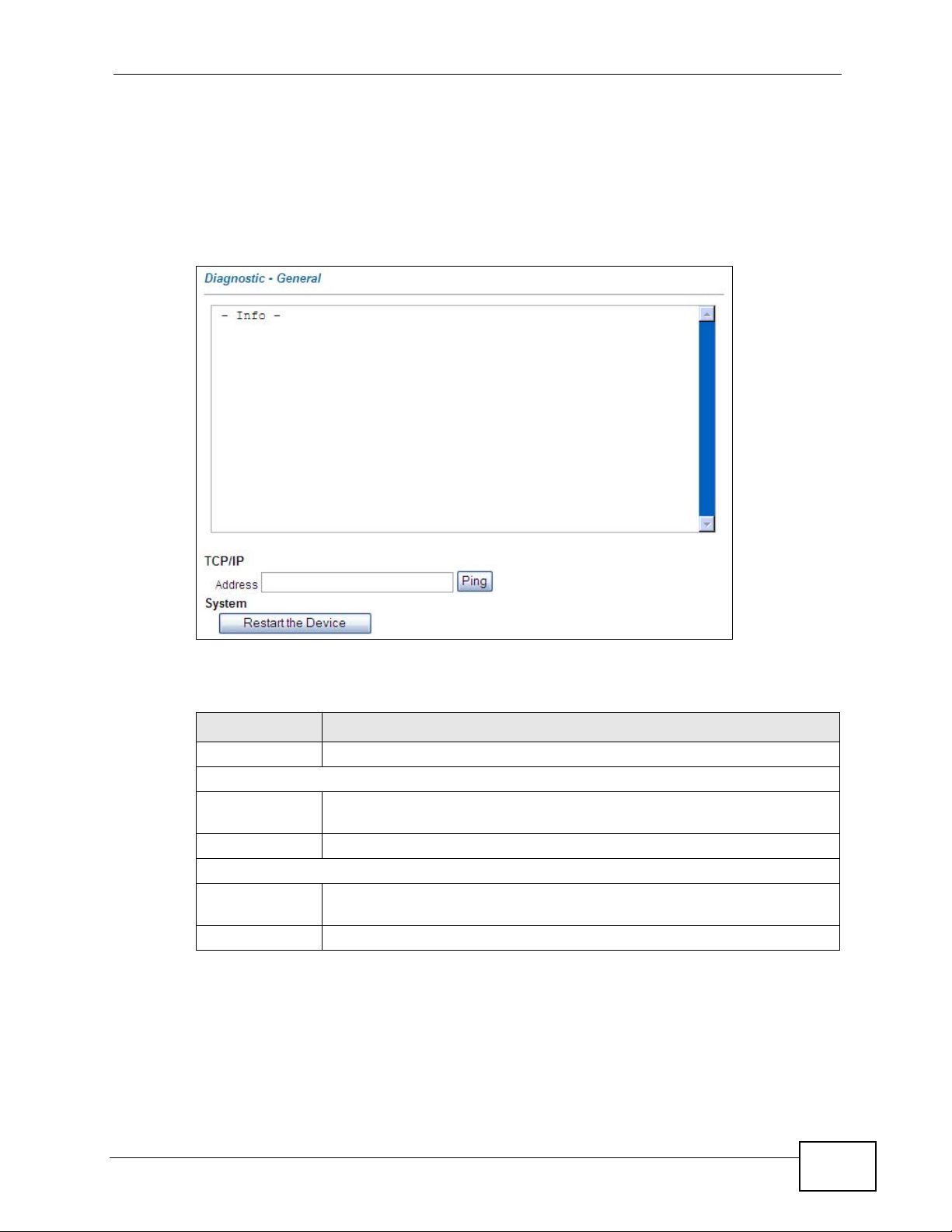
11.4 The Diagnostics Screen
Use the Diagnostics screen to ping a device to test the connection.
Click Maintenance > Diagnostic to display the screen.
Figure 30 Maintenance > Diagnostic
Chapter 11 Maintenance
The following table describes the labels in this screen.
Table 21 Maintenance > Diagnostic
LABEL DESCRIPTION
Info This read-only text box displays the ping test results.
TCP/IP
Address Type the IP address of a device that you want to ping in order to test a
connection.
Ping Click this button to begin the ping test.
System
Restart the
Device
Clear Results Click Clear Results to clear the Results text box.
Click this to restart the ZyXEL Device.
P-2900-4HB User’s Guide
85
Page 86

Chapter 11 Maintenance
86
P-2900-4HB User’s Guide
Page 87

PART IV
Product
Specification,
Appendices and
Index
Product Specifications (91)
Setting up Your Computer’s IP Address
(97)
Common Services (115)
Legal Information (119)
Index (123)
87
Page 88

88
Page 89

CHAPTER 12
Troubleshooting
12.1 Overview
This chapter offers some suggestions for solving problems you might encounter.
None of the LEDs turn on when you turn the power on.
• Make sure that you use the included power adapter to connect to the ZyXEL
Device and that it is plugged into an appropriate power source.
• Check all cable connections. If the LEDs still do not turn on, you may have a
hardware problem. In this case, you should contact your local vendor.
Cannot access the Internet.
• Check the condition of the coaxial cable connected to the back of the cable
modem. If the cable looks to be in poor condition, replace it.
• Check with your cable service provider if one of the PWR, DS and US LEDs is
not steady on.
• Check with your cable service provider if the ONLINE LED is off or blinking
slowly.
• Make sure your computer is configured correctly for TCP/IP networking(see
Setting Up Your Computer’s IP Address in the Quick Start Guide).
• Make sure your computer can communicate with the ZyXEL Device (either
through the LAN or the USB port). Use ping to check the connectivity. If you
cannot ping to the ZyXEL Device, do the following:
•Use the arp -d command to delete the existing Address Resolution Protocol
(ARP) table. Then try to ping to the ZyXEL Device again.
• If you want your computer to use a private IP address, make sure your
computer is configured as the same network as the ZyXEL Device’s LAN.
• If you want your computer to use a public IP address, make sure it is in the
same network as one of the ZyXEL Device’s WAN static IP.
P-2900-4HB User’s Guide
89
Page 90

Chapter 12 Troubleshooting
• If you want your computer to get a dynamic IP address assigned by a DHCP
server provided by your cable service provider, make sure your computer is
able to receive a dynamic IP address. You have to also disable the DHCP
Server function on the ZyXEL Device (select None in the DHCP field in the
Advanced Setup > LAN > LAN Setup screen, see Section 5.2 on page 51)
The USB LED is off.
• Check the USB cable connection. Unplug and plug in the USB cable.
• Check that your computer operating system is supported by the USB driver and
that it has been properly installed. Try installing the USB software again.
Cannot make a VoIP call.
• You should have applied for at least one phone number from your VoIP service
provider and the number(s) should be activated.
• Make sure you connect your telephone to the right port. Each PHONE port
maps to a unique number.
• Check the phone connection. Disconnect and connect the phone cable. The
PHONE LED for the connected port should light. Contact your VoIP service
provider if the PHONE LED still keeps off. If it is not, check that the phone wire
is not broken, the telephone is turned on and working and that the ZyXEL
Device is turned on and working.
•If the PHONE LED is on but you still cannot make a call, check that the DS, US,
and ONLINE LEDs are on. If they are not, you have an Internet access
problem. See Cannot access the Internet on page 89.
90
P-2900-4HB User’s Guide
Page 91
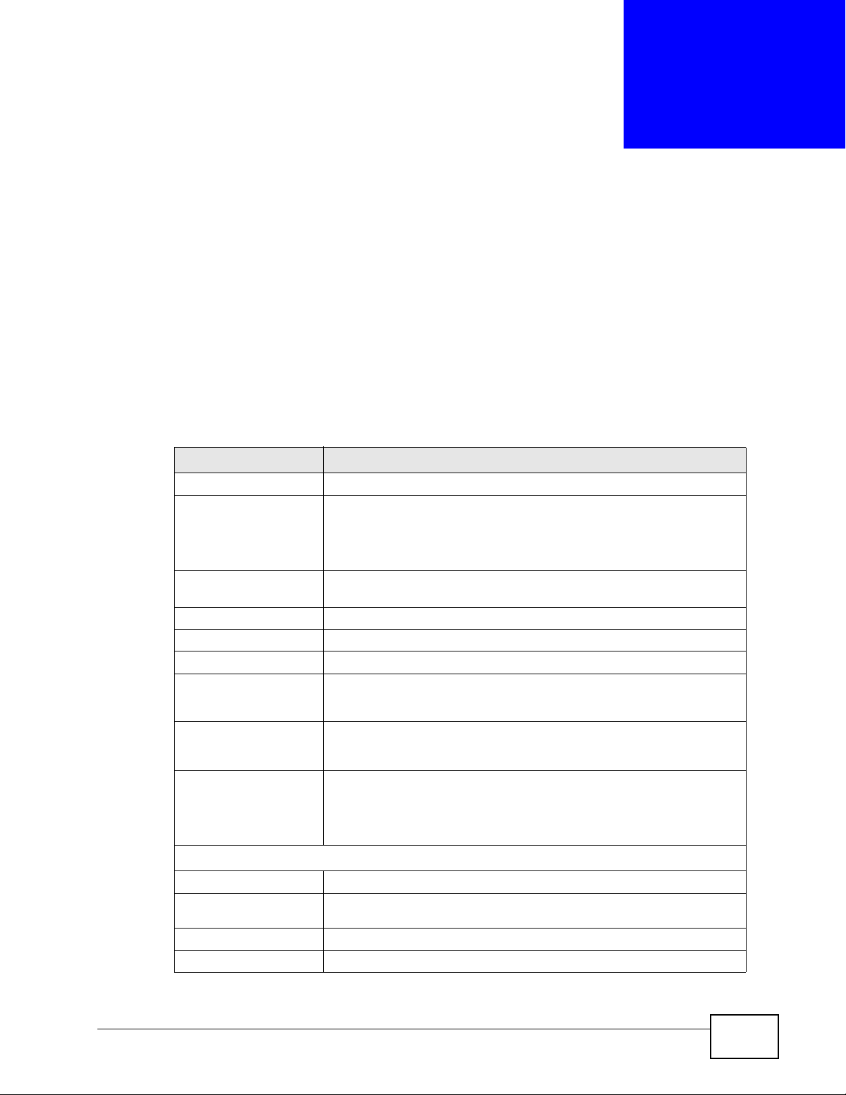
APPENDIX A
Product Specifications
See also the Introduction chapter for a general overview of the key features.
General ZyXEL Device Specifications
The following tables summarize the ZyXEL Device’s hardware and firmware
features.
Table 22 Hardware Specifications
SPECIFICATION DESCRIPTION
Dimensions 243.36 mm (W) x 160.98mm (D) x 40.74 mm (H)
Power Input: 100 - 240 VAC, 50/60 Hz
Output: 18 VDC 2A
CEC 4 complaint
Ethernet Ports Four auto-negotiating, auto MDI/MDI-X 10/100 Mbps RJ-45 Fast
Ethernet ports
USB Port One USB 1.1 B-type port for connecting to the ZyXEL Device
Cable Jack One cable jack for connecting a 75-ohm coaxial cable
Phone Ports Four RJ-11 FXS ports for VoIP applications
Operation
Environment
Storage Environment Temperature: -40º C ~ 70º C
Battery Two battery slots used for power supply backup
DOWNSTREAM CHANNEL
Center Frequency 91 to 857 MHZ
Channel
Bandwidth
Input Impedance 75 ohms (nominal)
Modulation 64 QAM or 256 QAM
Temperature: 0º C ~ 40º C
Humidity: 10% ~ 95% RH
Humidity: 10% ~ 95% RH
Standby time: up to eight hours
In use time: up to five hours
6 Mhz
P-2900-4HB User’s Guide
91
Page 92

Appendix A Product Specifications
Table 22 Hardware Specifications
SPECIFICATION DESCRIPTION
Maximum Data
rate
Symbol Rates 5.057 Msym/s for 64 QAM
Operating Level -15 to +15 dBmV
UPSTREAM CHANNEL
Frequency Range 5 to 42 Mhz
Bandwidth 200 Khz/400 Khz/800 Khz
Output Impedance 75 ohms (nominal)
Modulation 8*/16/32*/64*/128* QAM or QPSK
Maximum Data
Rate
Symbol Rates 160, 320, 640, 1280, 2560 and 5120* Ksym/s
Operating Level TDMA:
30 Mbps for 64 QAM
40 Mbps for 256 QAM
5.361 Msym/s for 256 QAM
1.6 Mhz/3.2 Mhz/6.4* Mhz
30 Mbps
+8 to +54 dBmV (32 QAM, 64QAM)
+8 to +55 dBmV (8 QAM, 16QAM)
+8 to +58 dBmV (QPSK)
S-CDMA:
+8 to +53 dBmV (all modulation types)
Table 23 Firmware Features
FEATURE DESCRIPTION
Default IP Address 192.168.1.1
Default Subnet Mask 255.255.255.0 (24 bits)
Default Administrator
User Name
Default Administrator
Password
High Speed Internet
Access
admin
1234
The ZyXEL Device supports transmission speeds of up to 43
Mbps upstream and 30 Mbps downstream. Actual speeds
attained depend on your cable operator’s CMTS (Cable Modem
Termination System).
92
Note: The standard your cable operator supports
determines the maximum upstream and downstream
speeds attainable. Actual speeds attained depend on
the distance from the cable operator’s central office,
noise, and so on.
P-2900-4HB User’s Guide
Page 93

Appendix A Product Specifications
Table 23 Firmware Features
FEATURE DESCRIPTION
Network Address
Translation (NAT)
Port Forwarding If you have a server (mail or web server for example) on your
DHCP (Dynamic Host
Configuration Protocol)
Routing Static IP only
Each computer on your network must have its own unique IP
address. Use NAT to convert your public IP address(es) to
multiple private IP addresses for the computers on your
network.
network, you can use this feature to let people access it from
the Internet.
Off by default. Use this feature to have the ZyXEL Device
assign IP addresses, an IP default gateway and DNS servers to
computers on your network. Your device can also act as a
surrogate DHCP server (DHCP Relay) where it relays IP address
assignment from the actual real DHCP server to the clients.
Relay - Supports up to five (5) IP addresses from a remote
DHCP server.
Server - Configurable IP address pool and limits on number of
DHCP clients.
Static IP with public DHCP
Static IP with NAT and private DHCP
Static IP with NAT
Dynamic DNS
Support
IP Multicast IP multicast is used to send traffic to a specific group of
Firmware Upgrade Download new firmware (when available) from the ZyXEL web
With Dynamic DNS (Domain Name System) support, you can
use a fixed URL, www.zyxel.com for example, with a dynamic
IP address. You must register for this service with a Dynamic
DNS service provider.
computers. The ZyXEL Device supports IGMP (Internet Group
Management Protocol) used to join multicast groups (see RFC
2236).
site and use the web configurator to put it on the ZyXEL
Device.
Note: Only upload firmware for your specific model!
Configuration Backup &
Restore
Logs Use logs for troubleshooting. You can send logs from the Z yXEL
IP Alias IP alias allows you to partition a physical network into logical
Make a copy of the ZyXEL Device’ s configuration. You can put it
back on the ZyXEL Device later if you decide to revert back to
an earlier configuration.
Device to an external syslog server.
networks over the same Ethernet interface. Your device
supports three logical LAN interfaces via its single physical
Ethernet interface with the your device itself as the gateway for
each LAN network.
P-2900-4HB User’s Guide
93
Page 94

Appendix A Product Specifications
Table 23 Firmware Features
FEATURE DESCRIPTION
Cable Modem Standards DOCSIS 2.0 compliant
Device Management Remote management through Web Configur ator (HTTP), Telnet,
External Antenna Detachable 2 dBi antenna
Security
DOCSIS Security
Type
PacketCable Security
Type
Packet filter DOCSIS packet filter
Alerts and Logs Logging: gateway activities, hacking attempts
DOCSIS 1.1/1.0 backward compatible
Packet Cable 1.5/1. 1 comp li a nt
TFTP
and SNMP (v1, v2 and v3)
Remote firmware upgrade
Syslog and alert
Baseline Privacy Interface (BPI) and BPI+
Support IPSec security mechanism:
• Voice traffic authentication: MD5 and SHA
• Voice traffic encryption: 3DES, AES and NULL
Media stream encryption: SRTP
Alerts: Email alerts based on filtering
Operating System Compatibility
Ethernet Connection Windows 95, Windows 98 SE, Windows 2000, Windows ME,
Windows XP, Macintosh, Linux and UNIX
USB Connection Window 98 SE, Windows 2000, Windows ME, Windows XP
Wall-mounting Instructions
Complete the following steps to hang your ZyXEL Device on a wall.
Note: See Table 32 on page 95 for the size of screws to use and how far apart to
place them.
1 Select a position free of obstructions on a sturdy wall.
2 Drill two holes for the screws.
Be careful to avoid damaging pipes or cables located inside the
wall when drilling holes for the screws.
94
P-2900-4HB User’s Guide
Page 95
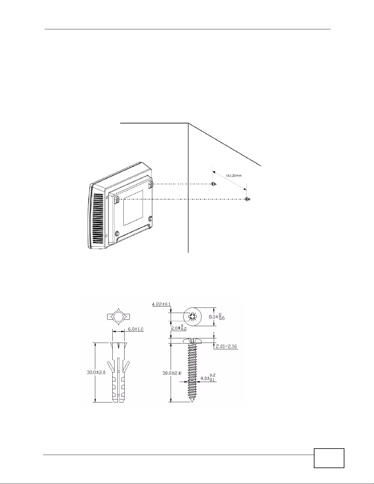
Appendix A Product Specifications
3 Do not insert the screws all the way into the wall. Leave a small gap of about 0.5
cm between the heads of the screws and the wall.
4 Make sure the screws are snugly fastened to the wall. They need to hold the
weight of the ZyXEL Device with the connection cables.
5 Align the holes on the back of the ZyXEL Device with the screws on the wall. Hang
the ZyXEL Device on the screws.
Figure 31 Wall-mounting Example
The following are dimensions of an M4 tap screw and masonry plug used for wall
mounting. All measurements are in millimeters (mm).
Figure 32 Masonry Plug and M4 Tap Screw
P-2900-4HB User’s Guide
95
Page 96

Appendix A Product Specifications
96
P-2900-4HB User’s Guide
Page 97

APPENDIX B
Setting up Your Computer’s IP
Address
All computers must have a 10M or 100M Ethernet adapter card and TCP/IP
installed.
Windows 95/98/Me/NT/2000/XP, Macintosh OS 7 and later operating systems and
all versions of UNIX/LINUX include the software components you need to install
and use TCP/IP on your computer. Windows 3.1 requires the purchase of a thirdparty TCP/IP application package.
TCP/IP should already be installed on computers using Windows NT/2000/XP,
Macintosh OS 7 and later operating systems.
After the appropriate TCP/IP components are installed, configure the TCP/IP
settings in order to "communicate" with your network.
If you manually assign IP information instead of using dynamic assignment, make
sure that your computers have IP addresses that place them in the same subnet
as the ZyXEL Device’s LAN port.
P-2900-4HB User’s Guide
97
Page 98
Appendix B Setting up Your Computer’s IP Address
Windows 95/98/Me
Click Start, Settings, Control Panel and double-click the Network icon to open
the Network window.
Figure 33 WIndows 95/98/Me: Network: Configuration
Installing Components
The Network window Configuration tab displays a list of installed components.
You need a network adapter, the TCP/IP protocol and Client for Microsoft
Networks.
If you need the adapter:
1 In the Network window, click Add.
2 Select Adapter and then click Add.
3 Select the manufacturer and model of your network adapter and then click OK.
If you need TCP/IP:
1 In the Network window, click Add.
2 Select Protocol and then click Add.
98
P-2900-4HB User’s Guide
Page 99

3 Select Microsoft from the list of manufacturers.
4 Select TCP/IP from the list of network protocols and then click OK.
If you need Client for Microsoft Networks:
1 Click Add.
2 Select Client and then click Add.
3 Select Microsoft from the list of manufacturers.
4 Select Client for Microsoft Networks from the list of network clients and then
click OK.
5 Restart your computer so the changes you made take effect.
Configuring
Appendix B Setting up Your Computer’s IP Address
1 In the Network window Configuration tab, select your network adapter's TCP/IP
entry and click Properties
2 Click the IP Address tab.
• If your IP address is dynamic, select Obtain an IP address automatically.
• If you have a static IP address, select Specify an IP address and type your
information into the IP Address and Subnet Mask fields.
Figure 34 Windows 95/98/Me: TCP/IP Properties: IP Address
P-2900-4HB User’s Guide
99
Page 100
Appendix B Setting up Your Computer’s IP Address
3 Click the DNS Configuration tab.
• If you do not know your DNS information, select Disable DNS.
• If you know your DNS information, select Enable DNS and type the
information in the fields below (you may not need to fill them all in).
Figure 35 Windows 95/98/Me: TCP/IP Properties: DNS Configuration
4 Click the Gateway tab.
• If you do not know your gateway’s IP address, remove previously installed
gateways.
• If you have a gateway IP address, type it in the New gateway field and click
Add.
5 Click OK to save and close the TCP/IP Properties window.
6 Click OK to close the Network window. Insert the Windows CD if prompted.
7 Turn on your ZyXEL Device and restart your computer when prompted.
Verifying Settings
1 Click Start and then Run.
2 In the Run window, type "winipcfg" and then click OK to open the IP
Configuration window.
3 Select your network adapter. You should see your computer's IP address, subnet
mask and default gateway.
100
P-2900-4HB User’s Guide
 Loading...