

Page 1
P-2812HNU-51c
Dual WAN VDSL2 IAD with 802.11n Wireless
Default Login Details
IP Address 192.168.1.1
User Name Admin account: admin
User account: user
Password Admin account: 1234
User account: user
Firmware Version 1.02
Edition 1, 06/2010
www.zyxel.com
www.zyxel.com
Copyright © 2010
ZyXEL Communications Corporation
Page 2

Page 3
About This User's Guide
About This User's Guide
Intended Audience
This manual is intended for people who want to configure the P-2812HNU-51c
using the web configurator.
Related Documentation
•Quick Start Guide
The Quick Start Guide is designed to help you get up and running right away. It
contains information on setting up your network and configuring for Internet
access.
• Support Disc
Refer to the included CD for support documents.
Documentation Feedback
Send your comments, questions or suggestions to: techwriters@zyxel.com.tw
Thank you!
The Technical Writing Team, ZyXEL Communications Corp.,
6 Innovation Road II, Science-Based Industrial Park, Hsinchu, 30099, Taiwan.
Need More Help?
More help is available at www.zyx el.com.
P-2812HNU-51c User’s Guide
3
Page 4

About This User's Guide
• Download Library
Search for the latest product updates and documentation from this link. Read
the Tech Doc Overview to find out how to efficiently use the User Guide, Quick
Start Guide and Command Line Interface Reference Guide in order to better
understand how to use your product.
• Knowledge Base
If you have a specific question about your product, the answer may be here.
This is a collection of answers to previously asked questions about ZyXEL
products.
•Forum
This contains discussions on ZyXEL prod ucts. Learn from others who use ZyXEL
products and share your experiences as well.
Customer Support
Should problems arise that cannot be solved by the methods listed above, you
should conta ct your vendor. If you cannot contact your vendor, then contact a
ZyXEL office for the region in which you bought the device.
See http://www.zyxel.com/web/contact_us.php for contact information. Please
have the following informatio n ready when you contact an office.
• Product model and serial number.
•Warranty Information.
• Date that you received your device.
• Brief description of the problem and the steps you took to solve it.
4
P-2812HNU-51c User’s Guide
Page 5

Document Conventions
Document Conventions
Warnings and Notes
These are how warnings and notes are shown in this User’s Guide.
Warnings tell you about things that could harm you or your device.
Note: Notes tell you other important information (for example, other things you may
need to configure or helpful tips) or recommendations.
Syntax Conventions
• The P-2812HNU-51c may be referred to as the “P-2812HNU-51c”, the “device”,
the “system” or the “product” in this User’s Guide.
• Product labels, screen names, field labels and field choices are all in bold font.
• A key stroke is denoted by square brackets and uppercase text, for example,
[ENTER] means the “enter” or “ret urn” key on your keyboard.
• “Enter” means for you to type one or more characters and then press the
[ENTER] key. “Select” or “choose” means for you to use one of the predefined
choices.
• A right angle bracket ( > ) within a screen name denotes a mouse click. For
example, Maintenance > Log > Log Setting means you first click
Maintenance in the navigation panel, then the Log sub menu and finally the
Log Setting tab to get to that screen.
• Units of measurement may denote the “metric” value or the “scientific” value.
For example, “k” for kilo may denote “1000” or “1024”, “M” for mega may
denote “1000000” or “1048576” and so on.
• “e.g.,” is a shorthand for “for instance”, and “i.e.,” means “that is” or “in other
words”.
P-2812HNU-51c User’s Guide
5
Page 6
Document Conventions
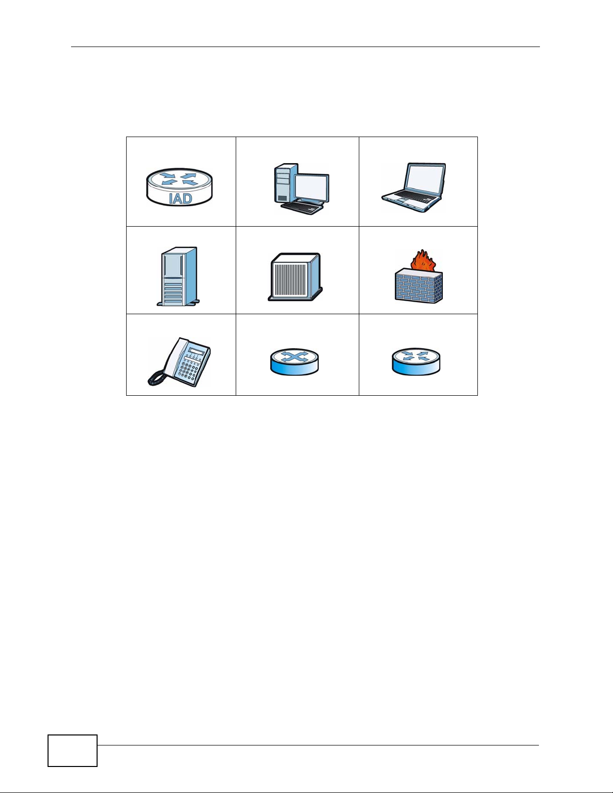
Icons Used in Figures
Figures in this User’s Guide may use the following generic icons. The P-2812HNU51c icon is not an exact representation of your device.
P-2812HNU-51c Computer Notebook computer
Server DSLAM Firewall
Telephone Switch Router
6
P-2812HNU-51c User’s Guide
Page 7

Safety Warnings
Safety Warnings
• Do NOT use this product near water, for example, in a wet basement or near a swimming
pool.
• Do NOT expose your device to dampness, dust or corrosive liquids.
• Do NOT store things on the device.
• Do NOT install, use, or service this device during a thunderstorm. There is a remote risk
of electric shock from lightning.
• Connect ONLY suitable accessories to the device.
• Do NOT open the device or unit. Opening or removing covers can expose you to
dangerous high voltage points or other risks. ONLY qualified service personnel should
service or disassemble this device. Please contact your vendor for further information.
• Make sure to connect the cables to the correct ports.
• Place connecting cables carefully so that no one will step on them or stumble over them.
• Always disconnect all cables from this device before servicing or disassembling.
• Use ONLY an appropriate power adaptor or cord for your device.
• Connect the power adaptor or cord to the right supply voltage (for example, 110V AC in
North America or 230V AC in Europe).
• Do NOT allow anything to rest on the power adaptor or cord and do NOT place the
product where anyone can walk on the power adaptor or cord.
• Do NOT use the device if the power adaptor or cord is damaged as it might cause
electrocution.
• If the power adaptor or cord is damaged, remove it from the device and the power
source.
• Do NOT attempt to repair the power adaptor or cord. Contact your local vendor to order a
new one.
• Do not use the device outside, and make sure all the connections are indoors. There is a
remote risk of electric shock from lightning.
• Do NOT obstruct the device ventilation slots, as insufficient airflow may harm your
device.
• Use only No. 26 AWG (American Wire Gauge) or larger telecommunication line cord.
• Antenna Warning! This device meets ETSI and FCC certification requirements when using
the included antenna(s). Only use the included antenna(s).
• If you wall mount your device, make sure that no electrical lines, gas or water pipes will
be damaged.
Your product is marked with this symbol, which is known as the WEEE mark. WEEE
stands for Waste Electronics and Electrical Equipment. It means that used electrical
and electronic products should not be mixed with general waste. Used electrical and
electronic equipment should be treated separately.
P-2812HNU-51c User’s Guide
7
Page 8

Safety Warnings
8
P-2812HNU-51c User’s Guide
Page 9

Contents Overview
Contents Overview
User’s Guide ........................................................................................................ ...................21
Introducing the P-2812HNU-51c ............................................................................................... 23
Tutorials ..................................................................................................................................... 33
Introducing the Web Configurator .............................................................................................. 73
Technical Reference ..............................................................................................................79
Status Screens .......................................................................................................................... 81
WAN Setup ............................ ............................................. ... .... ... ... ... ... .... ................................ 97
LAN Setup ...............................................................................................................................137
Wireless LAN ............................ ... .... ... ... ............................................. ... .... ... ... ... .... ................. 149
Network Address Translation (NAT) ........................................................................................ 183
Voice ............................................................ .................................................... ........................195
File Sharing ............................................................................................................................. 233
Sharing a USB Printer ............................................................................................................. 239
IPSec VPN ................... ... .............................................. ... ... ... .... ... ... ........................................ 253
Firewall .................................................................................................................................... 275
Certificate ................................................................................................................................ 281
Static Route ............................................................................................................................. 293
Policy Forwarding .................................................................................................................... 297
DNS Route ............................................ ... ... .... ............................................. ... ... .... ... ... ........... 301
RIP ............................... .................... ................... ................... .................... ..............................305
Quality of Service (QoS) ............................................................................ ... ... ... ..................... 307
Dynamic DNS Setup ................................................................................................................ 329
Remote Management ..............................................................................................................331
Universal Plug-and-Play (UPnP) ............................................................................................. 339
Parental Control .......................................................................................................................349
Interface Group ........................................................................................................................353
E-mail Notification .................................................................................................................... 359
System Settings ........... ............................................. .... ... ... ... .... ... ........................................... 363
Logs ........................................................................................................................................367
Tools ........................................................................................................................................ 371
Diagnostic .................................... ....................................................... ..................................... 379
Troubleshooting ..................................................... .................................................................. 385
Product Specifications ............................................................................................................. 395
P-2812HNU-51c User’s Guide
9
Page 10

Contents Overview
10
P-2812HNU-51c User’s Guide
Page 11

Table of Contents
Table of Contents
About This User's Guide..........................................................................................................3
Document Conventions............................................................................................................5
Safety Warnings ........................................................................................................................7
Contents Overview ...................................................................................................................9
Table of Contents....................................................................................................................11
Part I: User’s Guide................................................................................ 21
Chapter 1
Introducing the P-2812HNU-51c............................................................................................23
1.1 Overview ............. ............................................. ... .... ... ... ... .... ................................................ 23
1.2 Ways to Manage the P-2812HNU-51c ...................................................................... ... .... ... 24
1.3 Good Habits for Managing the P-2812HNU-51c .................................................................24
1.4 Applications for the P-2812HNU-51c ........ ... ... ............................................. .... ... ... ... ... .... ... 24
1.4.1 Internet Access ................................................ ... ... .... ............................................. ...24
1.4.2 VoIP Internet Calls ..................................................................................................... 27
1.4.3 USB File Sharing ........................................................................................................27
1.4.4 Wireless Connection ........... ... ... ... .............................................. ... ... ... .... ... ... ... ... .... ... 28
1.5 The RESET Button ............................. ... .... ... ... ............................................. .... ... ... ... ... ....... 29
1.5.1 Using the Reset Button ............. ... .... ... ... .................................................................... 29
1.6 LEDs (Lights) ......................... .... ... ... ............................................. ... .... ... ... ... .... ... ................ 30
Chapter 2
Tutorials...................................................................................................................................33
2.1 Overview ............. ............................................. ... .... ... ... ... .... ................................................ 33
2.2 How to Set up a Wireless Network ...................................................................................... 33
2.2.1 Example Parameters ........................... ... ... .... ... ... ... .... ... ............................................. 33
2.2.2 Configuring the AP ....... .... ... ... ... ... .... .......................................................................... 34
2.2.3 Configuring the Wireless Client .................................................................................. 36
2.3 How to Use ATM QoS with Multiple PVCs and Interface Groups ........... ... ... .... ... ... ... ... .... ... 43
2.3.1 Configuring PVCs ...................... ... .... ... ....................................................................... 44
2.3.2 Setting Interface Groups ..... ... ... ... .... ... ... ... .... ... ... ............................................. ... .... ... 53
2.3.3 Configuring Interface Group IP ........................................................ ... .... ... ... ... ... .... ... 57
2.3.4 Testing the DSL Connection Groups ... ... ... .... ... ... ... ............................................. .... ... 59
P-2812HNU-51c User’s Guide
11
Page 12

Table of Contents
2.4 How to Allow Out-of-band Remote Management from the WAN ............................ ............. 60
2.4.1 Configuring Multiple WAN Connections ................................. .... ... ... ... ....................... 60
2.4.2 Configuring Remote Management .............................................................................70
2.4.3 Testing the Connection .................................. ... ... ... .... ... ... .......................................... 71
Chapter 3
Introducing the Web Configurator ........................................................................................73
3.1 Web Configurator Overview ................................................................................................. 73
3.1.1 Accessing the Web Configurator ................................................................................ 73
3.2 Web Configurator Main Screen ........................................................................................... 74
3.2.1 Navigation Panel .......... .... ... ... ... ................................................................................. 75
3.2.2 Main Window .......................... ... ............................................. .... ... ... ... .... ... ... .............78
3.2.3 Status Bar ............................................... ... .............................................. ... ................ 78
Part II: Technical Reference.................................................................. 79
Chapter 4
Status Screens........................................................................................................................81
4.1 Overview ............. ............................................. ... .... ... ... ... .... ................................................ 81
4.2 Status Screen ............................... ... ... ... .... ... ... ... .............................................. ... ... ... .......... 82
4.2.1 3G Status: NeedPIN .................. ... .... ... ... ... .............................................. ... ... ... ... .... ... 87
4.2.2 3G Status: NeedPUK .......... ... ... ... .... ... ... ... .............................................. ... ... ... ... .... ... 88
4.2.3 WAN Service Statistics ............................................................................................... 89
4.2.4 Route Info ..................... .... ... ... ... ... .... ............................................. ... ... .... ... ... ... ..........90
4.3 VoIP Status ............ ... .... ... ............................................. ... .... ... ... .......................................... 92
4.3.1 WLAN Station List ............................................................................... .... ... ... ............. 94
4.3.2 LAN Statistics ............................ ... .... ... ... ... .............................................. ... ... ... ... ....... 95
4.3.3 Client List ............................................................................................ .... ... ... ... ..........96
Chapter 5
WAN Setup...............................................................................................................................97
5.1 Overview ............. ............................................. ... .... ... ... ... .... ................................................ 97
5.1.1 What Yo u Can Do in this Chapter .............................................................................. 97
5.2 What You Need to Know .................................. ... .... .............................................................99
5.3 Before You Begin ... ... .........................................................................................................101
5.4 The Layer 2 Interface Screen ............................................................................................ 101
5.4.1 Layer 2 Interface Configuration ........................................ ... ... .... ... ........................... 102
5.5 The Internet Connection Screen ........................................................................................ 105
5.5.1 Internet Connection Configuration ........................................................................... 107
5.6 The 3G Backup Screen ... ... ... .... ... ... ............................................. ... .... ... ... ... .... ... ... ... ... .....122
5.7 Technical Reference ........... ... .... ... ... ... ............................................................................... 125
12
P-2812HNU-51c User’s Guide
Page 13

Table of Contents
Chapter 6
LAN Setup..............................................................................................................................137
6.1 Overview ............. ............................................. ... .... ... ... ... .... .............................................. 137
6.1.1 What Yo u Can Do in this Chapter ............................................................................ 137
6.2 What You Need To Know .............. ..................................................................................... 138
6.3 The LAN IP Screen ............................................................................................................139
6.4 The LAN IPv6 Screen ........................................................................................................142
6.5 Technical Reference ........... ... .... ... ... ... ............................................................................... 143
Chapter 7
Wireless LAN.........................................................................................................................149
7.1 Overview ............. ............................................. ... .... ... ... ... .... .............................................. 149
7.1.1 What Yo u Can Do in this Chapter ............................................................................ 149
7.2 What You Need to Know .................................. ... .... ........................................................... 150
7.3 Before You Begin ... ... .........................................................................................................152
7.4 The General Screen ......................................................................................................... 153
7.4.1 No Security .......................... ... ............................................. ... .... ... ... ... .... .................155
7.4.2 WEP Encryption ..... ... ... .... ............................................. ... ... ... .... ... ... ... ..................... 156
7.4.3 WPA(2)-PSK ............................................................................................................ 157
7.4.4 WPA(2) Authentication .............................. .... ... ... ... .... ... ... ... ... .................................. 158
7.4.5 MAC Filter ........................................................................................................... 160
7.4.6 Adding a New MAC Filtering Rule ....................................................................... 161
7.5 The More AP Screen ........................................................................................................162
7.5.1 More AP Edit ............................................................................................................ 163
7.6 The WPS Screen ............................... ... .... ... ... ... ...............................................................163
7.7 The WPS Station Screen ..................................................................................................165
7.8 The WDS Screen ..............................................................................................................166
7.9 The Wireless Scheduling Screen ......................................................................................167
7.9.1 Adding a WLAN Power-off Scheduling Rule ............................................................ 169
7.10 The Advanced Setup Screen ..........................................................................................170
7.11 Technical Reference ........................................................................................................ 171
7.11.1 Wireless Network Overview ................................................................................... 172
7.11.2 Additional Wireless Terms ...................................................................................... 173
7.11.3 Wireless Security Overview ..... ... .... ... ... ... .... ... ... ... .... .............................................. 173
7.11.4 WiFi Protected Setup ............................................................................................. 175
Chapter 8
Network Address Translation (NAT)....................................................................................183
8.1 Overview ............... ............................................. .... ... ... ... .... ... ........................................... 183
8.1.1 What Yo u Can Do in this Chapter ............................................................................ 183
8.2 What You Need to Know .................................. ... .... ........................................................... 183
8.3 The Port Forwarding Screen ............................................................................................. 184
8.3.1 The Port Forwarding Edit Screen ............................................................................186
P-2812HNU-51c User’s Guide
13
Page 14

Table of Contents
8.4 The Trigger Port Screen ..................................... .... ... ... ................................................ .....187
8.4.1 Trigger Port Configuration ....................................................................................... 190
8.5 The DMZ Host Screen ....................................................................................................... 192
8.6 The ALG Screen ................................ ... .... ... ... ... .... ... ... ... .... .............................................. 192
8.7 Technical Reference ........... ... .... ... ... ... ............................................................................... 193
Chapter 9
Voice.......................................................................................................................................195
9.1 Overview ............. ............................................. ... .... ... ... ... .... .............................................. 195
9.1.1 What Yo u Can Do in this Chapter ............................................................................ 195
9.1.2 What You Need to Know About VoIP ......................... ... ... ... ... .... ... ... ... .... ... ... ........... 1 96
9.2 Before You Begin ... ... .........................................................................................................197
9.3 The SIP Settings Screen .................................................................................................. 197
9.4 The SIP Service Provider Screen ..................................................................................... 203
9.4.1 Dial Plan Rules ....................... ... ............................................. .... ... ... ... .... ................. 210
9.5 The Phone Region Screen ................................................................................................211
9.6 The Speed Dial Screen ......................................................................................................212
9.7 Call History Summary Screen ........................................................................................... 214
9.8 Outgoing Calls Screen .......................................................................................................215
9.9 Incoming Calls Screen .......................................................................................................216
9.10 Technical Reference ........................................................................................................216
9.10.1 Quality of Service (QoS) ........................................................................................225
9.10.2 Phone Services Overview ......................................................................................227
Chapter 10
File Sharing ...........................................................................................................................233
10.1 Overview .......................................................................................................................... 233
10.1.1 What You Can Do in this chapter ........................................................................... 233
10.1.2 What You Need to Know ........................................................................................ 234
10.1.3 Before You Begin ................................................................................................... 235
10.2 The File Sharing Screen ................................................................................................. 236
10.2.1 Example of Accessing Your Shared Files From a Computer ................................. 237
Chapter 11
Sharing a USB Printer ..........................................................................................................239
11.1 Overview .......................................................................................................................... 239
11.1.1 What You Can Do in this chapter ...................................................... .... ... ... ... ... .... . 239
11.2 What You Need to Know .................................................................................................. 240
11.3 Before You Begin ............................................................................................................. 240
11.4 The Print Server Screen .................................................................................................. 241
11.5 Add a New Printer Using Windows .................................................................................. 242
11.6 Add a New Printer Using Macintosh OS X ....................................................................... 245
11.6.1 Mac OS 10.3 and 10.4 ........................................................................................... 245
14
P-2812HNU-51c User’s Guide
Page 15

Table of Contents
11.6.2 Mac OS 10.5 and 10.6 ........................................................................................... 248
11.7 P-2812HNU-51c Print Server Compatible USB Printers .................................................. 252
Chapter 12
IPSec VPN..............................................................................................................................253
12.1 Overview .......................................................................................................................... 253
12.1.1 What You Can Do in this Chapter .......................................................................... 253
12.2 What You Need to Know .................................................................................................. 254
12.2.1 Before You Begin ................................................................................................... 255
12.3 The IPSec Screen .......................................................................................................... 255
12.3.1 The IPSec Setting Screen ..................................................................................... 256
12.3.2 Manual Key Setup ............................. .......................................... ........................... 261
12.3.3 Configuring Manual Key ................................... .......................................... ........... 262
12.4 Viewing VPN St atus ........................................................................................................ 266
12.5 IPSec VPN Technical Reference .....................................................................................267
12.5.1 IPSec Architecture ................................................................................................. 267
12.5.2 Encapsulation ......................................................................................................... 268
12.5.3 IKE Phases ........................................................................................................... 269
12.5.4 Negotiation Mode ...................................................................................................270
12.5.5 IPSec and NAT .......................................................................................................270
12.5.6 VPN, NAT, and NAT Traversal ............................................................................... 271
12.5.7 ID Type and Content .............................................................................................. 272
12.5.8 Pre-Shared Key ...................................................................................................... 274
12.5.9 Diffie-Hellman (DH) Key Groups ............................................................................ 274
Chapter 13
Firewall...................................................................................................................................275
13.1 Overview ......................................................................................................................... 275
13.1.1 What You Can Do in this Chapter .......................................................................... 275
13.2 What You Need to Know .................................................................................................. 275
13.3 The Firewall Screen ................. ... ... ... ... ................................................. ... ... .... ................. 276
13.3.1 Creating Incoming Firewall Rules ........................................................................ 278
Chapter 14
Certificate ..............................................................................................................................281
14.1 Overview .......................................................................................................................... 281
14.1.1 What You Can Do in this Chapter .......................................................................... 281
14.2 What You Need to Know .................................................................................................. 281
14.3 The Local Certificates Screen ......................................................................................... 282
14.3.1 Create Certificate Request .................................................................................... 283
14.3.2 Import Certificate . ... ... .... ................................................ ... ... .................................. 284
14.3.3 Certificate Details .................................................................................................. 286
14.3.4 Load Signed Certificate .......................................................................................... 288
P-2812HNU-51c User’s Guide
15
Page 16

Table of Contents
14.4 The Trusted CA Screen .................................... ............................................................... 289
14.4.1 View Trusted CA Certificate ...................................................................................291
14.4.2 Import Trusted CA Certificate ................................................................................. 292
Chapter 15
Static Route...........................................................................................................................293
15.1 Overview ....................................................................................................................... 293
15.1.1 What You Can Do in this Chapter .......................................................................... 293
15.2 The Static Route Screen .................................................................................................. 294
15.2.1 Static Route Edit ................................................................................................... 295
Chapter 16
Policy Forwarding.................................................................................................................297
16.1 Overview ....................................................................................................................... 297
16.1.1 What You Can Do in this Chapter .......................................................................... 297
16.2 The Static Route Screen .................................................................................................. 297
16.2.1 Policy Forwarding Setup ...................................................................................... 298
Chapter 17
DNS Route.............................................................................................................................301
17.1 Overview ....................................................................................................................... 301
17.1.1 What You Can Do in this Chapter .......................................................................... 302
17.2 The DNS Route Screen ................................................................................................... 302
17.2.1 DNS Route Edit .................................................................................................... 303
Chapter 18
RIP..........................................................................................................................................305
18.1 Overview ....................................................................................................................... 305
18.1.1 What You Can Do in this Chapter .......................................................................... 305
18.2 The RIP Screen ... ... .... ... ... ... .... ... ................................................ ... .... ... ........................... 305
Chapter 19
Quality of Service (QoS).......................................................................................................307
19.1 Overview ......................................................................................................................... 307
19.1.1 What You Can Do in this Chapter .......................................................................... 307
19.2 What You Need to Know .................................................................................................. 308
19.3 The Quality of Service General Screen .......................................................................... 309
19.4 The Queue Setup Screen .................................................................................................311
19.4.1 Adding a QoS Queue ............................................................................................ 312
19.5 The Class Setup Screen ................................................................................................ 313
19.5.1 QoS Class Edit ...................................................................................................... 315
19.6 The QoS Policer Setup Screen ....................................................................................... 319
19.6.1 Adding a QoS Policer ............................................................................................ 320
16
P-2812HNU-51c User’s Guide
Page 17

Table of Contents
19.7 The QoS Monitor Screen ................................................................................................ 323
19.8 Technical Reference ........................................................................................................324
Chapter 20
Dynamic DNS Setup .............................................................................................................329
20.1 Overview ......................................................................................................................... 329
20.1.1 What You Can Do in this Chapter .......................................................................... 329
20.2 What You Need To Know .................................................................................................329
20.3 The Dynamic DNS Screen ................................................ ... ... ... ... .... ... ... ... .... ... ... ........... 3 30
Chapter 21
Remote Management............................................................................................................331
21.1 Overview .......................................................................................................................... 331
21.1.1 What You Can Do in this Chapter .......................................................................... 331
21.2 The TR-069 Screen .........................................................................................................331
21.3 The TR-064 Screen .........................................................................................................333
21.4 The SNMP Screen ...........................................................................................................334
21.5 The Service Control Screen ............................................................................................ 336
21.6 The IP Address Screen ................................................................................................... 337
21.6.1 Adding an IP Address ............................................................................................338
Chapter 22
Universal Plug-and-Play (UPnP)..........................................................................................339
22.1 Overview ......................................................................................................................... 339
22.1.1 What You Can Do in this Chapter .......................................................................... 339
22.2 What You Need to Know .................................................................................................. 339
22.3 The UPnP Screen ............................................................................................................340
22.4 Installing UPnP in Windows .................................. ............................. ............................. . 341
22.4.1 Windows 7 .............................................................................................................. 341
22.4.2 Windows XP ........................................................................................................... 342
22.5 Using UPnP in Windows XP ............................................................................................ 343
22.5.1 Auto-discover Your UPnP-enabled Network Device .............................................. 344
22.5.2 Web Configurator Easy Access ............................................................................. 346
Chapter 23
Parental Control....................................................................................................................349
23.1 Overview .......................................................................................................................... 349
23.1.1 What You Can Do in this Chapter .......................................................................... 349
23.2 The Time Restriction Screen ........................................................................................... 349
23.2.1 Adding a Schedule ................................................................................................. 350
23.3 The URL Filter Screen .....................................................................................................351
23.3.1 Adding URL Filter ................................................................................................... 352
P-2812HNU-51c User’s Guide
17
Page 18

Table of Contents
Chapter 24
Interface Group.....................................................................................................................353
24.1 Overview .......................................................................................................................... 353
24.1.1 What You Can Do in this Chapter .......................................................................... 353
24.2 The Interface Group Screen ............................................................................................ 353
24.2.1 Interface Group Configuration ................................................................................355
24.2.2 Interface Grouping Criteria .....................................................................................356
Chapter 25
E-mail Notification ................................................................................................................359
25.1 Overview ....................................................................................................................... 359
25.1.1 What You Can Do in this Chapter .......................................................................... 359
25.2 The Email Notification Screen ......................................................................................... 359
25.2.1 Email Notification Edit .......................................................................................... 360
Chapter 26
System Settings....................................................................................................................363
26.1 Overview .......................................................................................................................... 363
26.1.1 What You Can Do in this Chapter .......................................................................... 363
26.2 The General Screen ........................................................................................................363
26.3 The Time Setting Screen ................................................................................................ 364
Chapter 27
Logs ......................................................................................................................................367
27.1 Overview ......................................................................................................................... 367
27.1.1 What You Can Do in this Chapter .......................................................................... 367
27.2 The View Log Screen ...................................................................................................... 367
27.3 The Log Settings Screen ..... .... ... ...... ... .... ........................................................................ 368
Chapter 28
Tools.......................................................................................................................................371
28.1 Overview .......................................................................................................................... 371
28.1.1 What You Can Do in this Chapter .......................................................................... 371
28.2 The Firmware Screen ...................................................................................................... 372
28.3 The Configuration Screen ................................................................................................ 374
28.4 The Restart Screen .........................................................................................................376
Chapter 29
Diagnostic..............................................................................................................................379
29.1 Overview .......................................................................................................................... 379
29.1.1 What You Can Do in this Chapter .......................................................................... 379
29.2 What You Need to Know .................................................................................................. 379
29.3 The General Diagnostic Screen ...................................................................................... 380
18
P-2812HNU-51c User’s Guide
Page 19

Table of Contents
29.4 The 802.1ag Screen ........................................................................................................381
29.5 The OAM Ping Test Screen ............................................................................................. 383
Chapter 30
Troubleshooting....................................................................................................................385
30.1 Power, Hardware Connections, and LEDs .............................. ... ... .... ... ... ... .... ... ... ... ........385
30.2 P-2812HNU-51c Access and Login ......................... ....................................................... .386
30.3 Internet Access ................................................................................................................ 388
30.4 Phone Calls and VoIP ......................................................................................................391
30.5 USB Device Connection .................................................................................................. 391
30.6 Wireless LAN Troubleshooting ........................................................................................ 392
30.7 UPnP ............................................................................................................................... 392
Chapter 31
Product Specifications.........................................................................................................395
31.1 Hardware Specifications ..................................................................................................395
31.2 Firmware Specifications ...................................................................................................396
Appendix A Network Troubleshooting..................................................................................401
Appendix B Setting Up Your Computer’s IP Address...........................................................417
Appendix C Pop-up Windows, JavaScripts and Java Permissions......................................445
Appendix D IP Addresses and Subnetting...........................................................................455
Appendix E Wireless LANs ..................................................................................................467
Appendix F IPv6...................................................................................................................483
Appendix G Common Services............................................................................................493
Appendix H Open Software Announcements.......................................................................497
Appendix I Legal Information................................................................................................511
Index.......................................................................................................................................515
P-2812HNU-51c User’s Guide
19
Page 20

Table of Contents
20
P-2812HNU-51c User’s Guide
Page 21

PART I
User’s Guide
21
Page 22

22
Page 23

CHAPTER 1
Introducing the P-2812HNU-51c
1.1 Overview
The P-2812HNU-51c is a VDSL2 Integrated Access Device (IAD) that combines a
VDSL2+ router with Voice over IP (VoIP) communication capabilities. You may
access the Internet in one of these ways:
• You can have super-fast, secure Internet access over analog (PO TS) telephone
lines. The P-2812HNU-51c supports both Packet Transfer Mode (PTM) and
Asynchronous T ransfer Mode (ATM) and can be backward compatible with ADSL,
ADSL2 and ADSL2+.
• You can use an Ethernet WAN port for Internet access through the Ethernet
WAN connection.
• You can use 3G as your WAN and access the Internet via a 3G network.
The P-2812HNU-51c also allows you to use a traditional analog telephone to make
Internet calls. Y ou can use Quality of Service (QoS) t o efficiently manage traffi c on
your network by giving priority to certain types of traffic and/or to particular
computers.
Please refer to the following description of the product name format.
• “H” denotes an integrated 4-port hu b (swi tch).
• “N” denotes IEEE 802.11n wireless functionality . There is an embedded mini-PCI
module for IEEE 802.11b/g/n wireless LAN connectivity.
• “U” denotes a USB port used to set up a 3G WAN connection via a 3G wireless
card or share files via a USB memory stick or a USB hard drive. The P2812HNU-51c can also function as a print server with an USB printer connected.
Only use firmware for your P-2812HNU-51c’s specific model. Refer
to the label on the bottom of your P-2812HNU-51c.
Models ending in “1”, for example P-2812HNU-51c, denote a device that works
over the analog telephone system, POTS (Plain Old Telephone Service).
See Chapter 31 on page 395 for a full list of features.
P-2812HNU-51c User’s Guide
23
Page 24

Chapter 1 Introducing the P-2812HNU-51c
1.2 Ways to Manage the P-2812HNU-51c
Use any of the following methods to manage the P-2812HNU-51c.
• Web Configurator. This is recommended for everyday management of the P2812HNU-51c using a (supported) web browser.
• SNMP. The device can be monitored by an SNMP manager. See the SNMP
chapter in this User’s Guide.
• TR-069. This is an auto-configuration server used to remotely configure your
device.
1.3 Good Habits for Managing the P-2812HNU51c
Do the following things regularly to make the P-2812HNU-51c more secure and to
manage the P-2812HNU-51c more effectively.
• Change the password. Use a password that’s not easy to guess and that consists
of different types of characters, such as numbers and letters.
• Write down the password and put it in a safe place.
• Back up the configuration (and make sure you know how to restore it).
Restoring an earlier working configuration may be useful if the device becomes
unstable or even crashes. If you forget y our password, you will hav e to reset the
P-2812HNU-51c to its factory default settings. If you backed up an earlier
configuration file, you would not have to totally re-configure the P-2812HNU51c. You could simply restore your last configuration.
1.4 Applications for the P-2812HNU-51c
Here are some example uses for which the P-2812HNU-51c is well suited.
1.4.1 Internet Access
You can have up to eight WAN services over one ADSL, VDSL or Ethernet WAN
line. The P-2812HNU-51c cannot work in ADSL, VDSL and Ethernet W AN mode at
the same time.
24
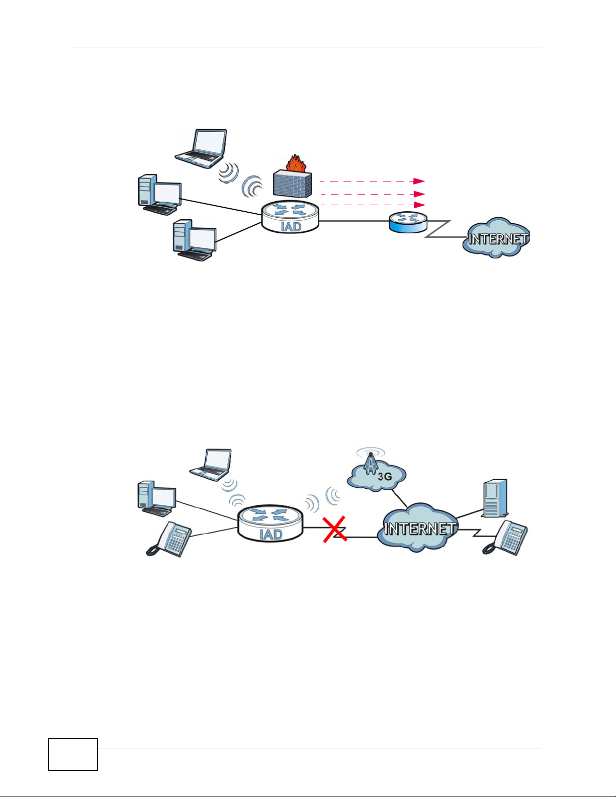
Computers can connect to the P-2812HNU-51c’s LAN ports (or wirelessly).
You can also configure IP filtering on the P-2812HNU-51c for secure Internet
access. When the IP filter is on, all incoming traffic from the Internet to your
P-2812HNU-51c User’s Guide
Page 25
network is blocked by default unless it is initiated from your network. This means
that probes from the outside to your network are not allowed, but you can safely
browse the Internet and download files.
1.4.1.1 DSL
Your P- 2812HNU-5 1c provi des shared Internet ac cess b y connecting the DSL p ort
to the DSL or MODEM jack on a splitter or your telephone jack.
Figure 1 Internet Access Application: DSL
Chapter 1 Introducing the P-2812HNU-51c
LAN
LAN
WAN
Bridging
IPoE
PPPoE
ADSL / VDSL
WAN
IPoA / PPPoA
ADSL
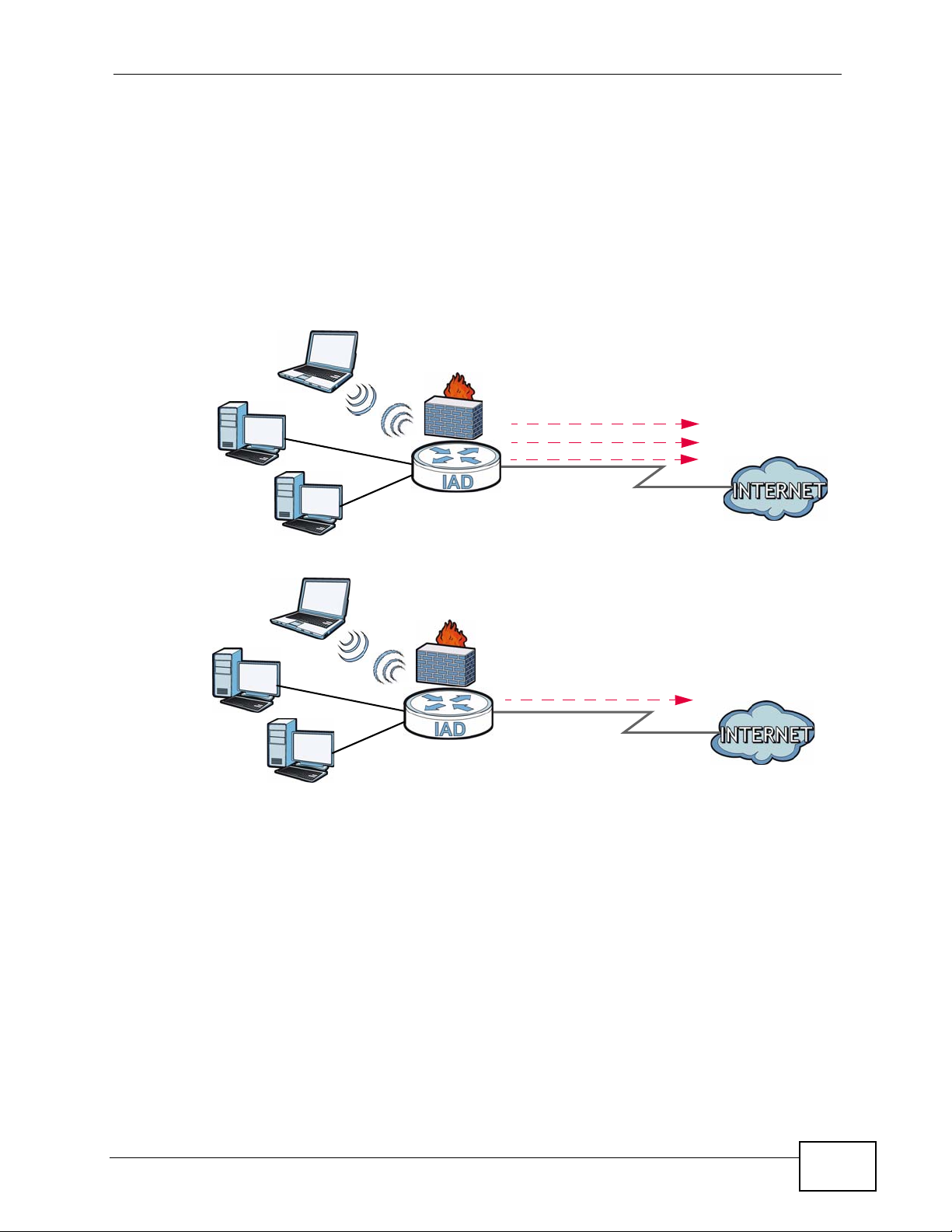
1.4.1.2 Ethernet WAN
If you prefer not to use a DSL line and you have another broadband modem or
router (such as ADSL) availab le, y ou c a n push the DSL/WAN switch (on the rear
panel) to the WAN side and connect the WAN port to the broadband modem or
P-2812HNU-51c User’s Guide
25
Page 26
Chapter 1 Introducing the P-2812HNU-51c
router. This way, you can access the Internet via an Ethernet connection and still
use the QoS, Firewall and VoIP functions on the P-2812HNU-51c.
Figure 2 Internet Access Application: Ethernet WAN
LAN
1.4.1.3 3G WAN
The USB port allows you to wirelessly connect to a 3G netowk to get Internet
access by attaching a 3G wireless card. You must leave the DSL or Ethernet WAN
port unconnected and attached a 3G wireless card to use 3G as your WAN. You
can also heve the P-2812HNU-51c use the 3G WAN connection as a backup. That
means the P-2812HNU-51c switches to the 3G wireless WAN connection after the
wired DSL or Ethernet WAN connection fails. The P-2812HNU-51c automatically
changes back to use the wired DSL or Ethernet WAN connection when it is
available.
Figure 3 Internet Access Application: 3G WAN
WAN
Bridging
IPoE
PPPoE
Ethernet
DSL
26
P-2812HNU-51c User’s Guide
Page 27
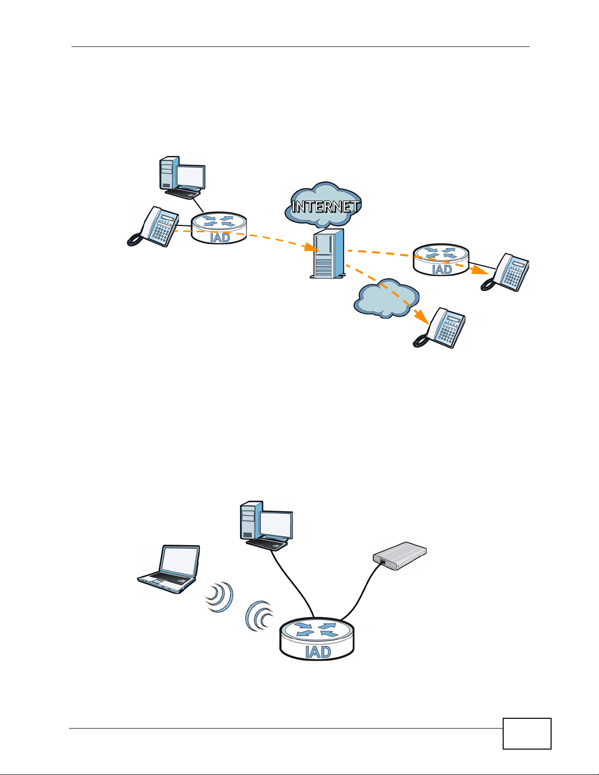
1.4.2 VoIP Internet Calls
You can register up to two SIP (Session Initiation Protocol) accounts and use the
P-2812HNU-51c to make and receive VoIP telephone calls:
Figure 4 P-2812HNU-51c’s VoIP Application
Chapter 1 Introducing the P-2812HNU-51c
• Calls via a VoIP service provider (A) - The P-2812HNU-51c sends your call to a
VoIP service provider’s SIP server which forwards your calls to either VoIP or
PSTN phones.
1.4.3 USB File Sharing
Use the built-in USB 2.0 ports to share files via a USB memory stick or a USB hard
drive (A). You can connect one USB hard drive to the P-2812HNU-51c at a time.
Figure 5 USB File Sharing Application
A
PSTN
A
P-2812HNU-51c User’s Guide
27
Page 28
Chapter 1 Introducing the P-2812HNU-51c
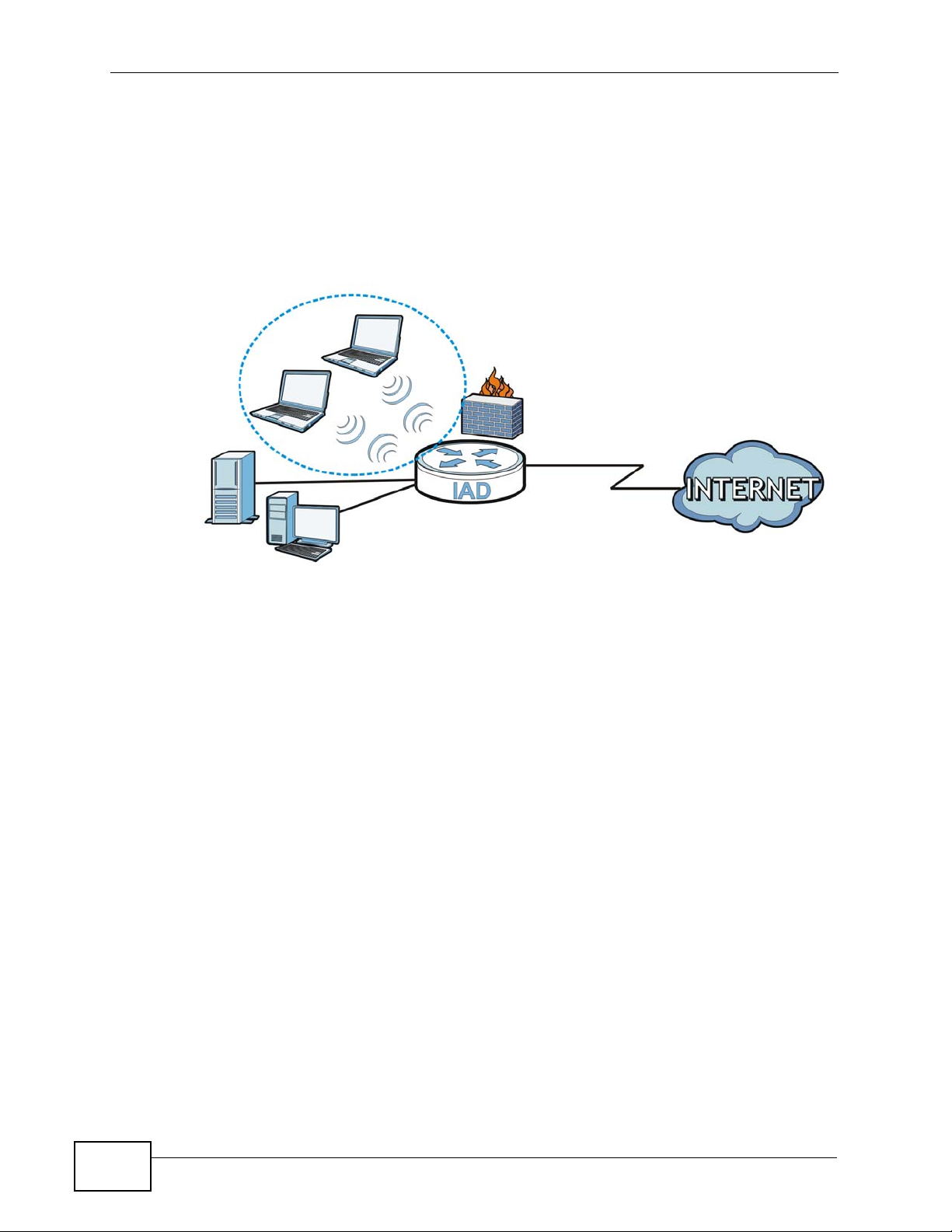
1.4.4 Wireless Connection
By default, the wireless LAN (WLAN) is enabled on the P-2812HNU-51c. IEEE
802.11a/b/g/n compliant clients can wirelessly connect to the P-2812HNU-51c to
access network resources. You can set up a wireless network with WPS (WiFi
Protected Setup) or manually add a client to your wireless network.
Figure 6 Wireless Connection Application
WLAN
WAN
LAN
1.4.4.1 The WPS Button
You can use the WPS button on the rear panel of the device to turn the wireless
LAN off or on. You can also use it to activate WPS in order to quickly set up a
wireless network with strong security.
Turn the Wireless LAN Off or On
1 Make sure the POWER LED is on (not blinking).
2 Press the WPS button for one second and release it. The WLAN/WPS LED should
change from on to off or vice versa.
Activate WPS
1 Make sure the POWER LED is on (not blinking).
2 Press the WPS button for more than five seconds and release it. Press the WPS
button on another WPS -enabled device within range of the P-2812HNU-51c. The
WLAN/WPS LED should flash while the P-2812HNU-51c sets up a WPS
connection with the wireless device.
28
P-2812HNU-51c User’s Guide
Page 29

Note: You must activate WPS in the P-2812HNU-51c and in another wireless device
within two minutes of each other. See Section 7.11.4 on page 175 for more
information.
1.5 The RESET Button
If you forget your password or cannot access the web configurator, you will need
to use the RESET button at the back of the device to reload the factory-default
configuration file. This means that you will lose all configurations that you had
previously and the password will be reset to “1234”.
1.5.1 Using the Reset Button
1 Make sure the POWER LED is on (not blinking).
2 To set the device back to the factory default settings, press the RESET button for
ten seconds or until the POWER LED begins to blink and then release it. When the
POWER LED begins to blink, the defaults have been restored and the device
restarts.
Chapter 1 Introducing the P-2812HNU-51c
P-2812HNU-51c User’s Guide
29
Page 30

Chapter 1 Introducing the P-2812HNU-51c
1.6 LEDs (Lights)
The following graphic displays the labels of the LEDs.
Figure 7 LEDs on the Device
30
P-2812HNU-51c User’s Guide
Page 31

Chapter 1 Introducing the P-2812HNU-51c
None of the LEDs are on if the P-2812HNU-51c is not receiving power.
Table 1 LED Descriptions
LED
PWR/SYS Green On The P-2812HNU-51c is receiving power and ready for
PHONE 1/2 Green On A SIP account is registered for the phone port.
USB Green On The P-2812HNU-51c recognizes a USB connection.
WAN Green On The P-2812HNU-51c has an Ethernet connection with a
ETHERNET
1-4
COLO
R
Red On The P-2812HNU-51c detected an error while self-testing,
Orange On A SIP account is registered for the phone port and there
Green On The P-2812HNU-51c has a successful 1000 Mbps
Orange On The P-2812HNU-51c has a successful 10/100 Mbps
STATUS DESCRIPTION
use.
Blinking The P-2812HNU-51c is self-testing.
or there is a device malfunction.
Off The P-2812HNU-51c is not receiving power.
Blinking A telephone connected to the phone port has its receiver
off of the hook or there is an incoming call.
is a voice message in the corresponding SIP account.
Blinking A telephone connected to the phone port has its receiver
off of the hook and there is a voice message in the
corresponding SIP account.
Off The phone port does not have a SIP account registered.
Blinking The P-2812HNU-51c is sending/receiving data to /from
the USB device connected to it.
Off The P-2812HNU-51c does not detect a USB connection.
device on the WAN.
Blinking The P-2812HNU-51c is sending/receiving data to/from
the WAN.
Off The P-2812HNU-51c does not have an Ethernet
connection with the WAN.
Ethernet connection with a device on the Local Area
Network (LAN).
Blinking The P-2812HNU-51c is sending or receiving data to/from
the LAN at 1000 Mbps.
Ethernet connection with a device on the Local Area
Network (LAN).
Blinking The P-2812HNU-51c is sending or receiving data to/from
the LAN at 10/100 Mbps.
Off The P-2812HNU-51c does not have an Ethernet
connection with the LAN.
P-2812HNU-51c User’s Guide
31
Page 32

Chapter 1 Introducing the P-2812HNU-51c
Table 1 LED Descriptions
LED
WLAN/
WPS
DSL Green On The ADSL line is up.
INTERNET Green On The P-2812HNU-51c has an IP connection but no traffic.
COLO
R
Green On The wireless network is activated and is operating in IEEE
Orange Blinking The P-2812HNU-51c is setting up a WPS connection.
Orange On The VDSL line is up.
Red On The P-2812HNU-51c attempted to make an IP connection
STATUS DESCRIPTION
Blinking The P-2812HNU-51c is communicating with other
Off The wireless network is not activated.
Blinking The P-2812HNU-51c is initializing the ADSL line.
Blinking The P-2812HNU-51c is initializing the VDSL line.
Off The DSL line is down.
Blinking The P-2812HNU-51c is sending or receiving IP traffic.
Off The P-2812HNU-51c does not have an IP connection.
802.11b/g mode.
wireless clients.
Your device has a WAN IP address (either static or
assigned by a DHCP server), PPP negotiation was
successfully completed (if used) and the DSL connection
is up.
but failed. Possible causes are no response from a DHCP
server, no PPPoE response, PPPoE authentication failed.
Refer to the Quick Start Guide for information on hardware connections.
32
P-2812HNU-51c User’s Guide
Page 33

CHAPTER 2
Tutorials
2.1 Overview
This chapter describes:
• How to Set up a Wireless Network on page 33.
• How to Use ATM QoS with Multiple PVCs and Interface Groups on page 43.
• How to Allow Out-of-band Remote Management from the WAN on page 60.
Note: The tutorials featured in this chapter require a basic understanding of
connecting to and using the Web Configurator on your P-2812HNU-51c. For
details, see the included Quick Start Guide. For field descriptions of individual
screens, see the related technical reference in this User's Guide.
2.2 How to Set up a Wireless Network
This tutorial gives you examples of how to set up an access point and wireless
client for wireless communication using the following parameters. The wireless
clients can access the Internet th roug h an AP wirelessly.
2.2.1 Example Parameters
SSID SSID_Example3
Security WPA-PSK
(Pre-Shared Key: ThisismyWPA-PSKpre-sharedkey)
802.11 mode IEEE 802.11b/g/n Mixed
An access point (AP) or wireless router is referred to as “AP” and a computer with
a wireless network card or USB/PCI adapter is referred to as “wireless client” here.
We use the P-2812HNU-51c web screens and M-302 utility screens as an example.
The screens may vary slightly for different models.
P-2812HNU-51c User’s Guide
33
Page 34

Chapter 2 Tutorials
2.2.2 Configuring the AP
Follow the steps below to configure the wireless settings on your AP.
1 Open the Network > Wireless LAN screen in the AP’s web configurator.
Figure 8 AP: Wireless LAN
34
2 Make sure the Active Wireless LAN check box is selected.
3 Enter “SSID_Example3” as the SSID and select Auto to have the P-2812HNU-51c
automatically determine a channel which is not used by another AP.
4 Set security mode to WPA-PSK and enter “ThisismyWPA-PSKpre-sharedkey” in
the Pre-Shared Key field. Click Apply.
P-2812HNU-51c User’s Guide
Page 35

Chapter 2 Tutorials
5 Click the Advanced Setup tab and select 802.11b/g/n Mixed in the 802.11
Mode field. Click Apply.
Figure 9 AP: Wireless LAN > Advanced Setup
6 Open the Status screen.Verify your wireless and wireless security settings under
Device Information and check if the WLAN connection is up under Interface
Status.
Figure 10 AP: Status
P-2812HNU-51c User’s Guide
35
Page 36

Chapter 2 Tutorials
7 Click the WLAN Station List hyperlink in the AP’s Status screen. You ca n see if
any wireless client has connected to the AP.
Figure 11 AP: Status: WLAN Station List
2.2.3 Configuring the Wireless Client
This section describes how to connect the wireless client to a network.
2.2.3.1 Connecting to a Wireless LAN
The following sections show you how to join a wireless network using the ZyXEL
utility, as in the following diagram. The wireless client is labeled C and the access
point is labeled AP.
C
There are three ways to connect the client to an access point.
• Configure nothing and leave the wireless client to automatically scan for and
connect to any available network that has no wireless security configured.
• Manually connect to a network.
AP
36
• Configure a profile to have the wireless client automatically connect to a specific
network or peer computer.
P-2812HNU-51c User’s Guide
Page 37

Chapter 2 Tutorials
This example illustrates how to manually connect your wireless cli ent to an access
point (AP) which is configured for WPA-PSK security and connected to the
Internet. Before you connect to the access point, you must know its Service Set
IDentity (SSID) and WPA-PSK pre-shared key. In this example, the SSID is
“SSID_Example3” and the pre-shared key is “ThisismyWPA-PSKpre-sharedkey”.
After you install the ZyXEL utility and then insert the wireless client, follow the
steps below to connect to a network using the Site Survey screen.
1 Open the ZyXEL utility and click the Site Survey tab to open the screen shown
next.
Figure 12 ZyXEL Utility: Site Survey
2 The wireless client automatically searches for available wireless networks. Click
Scan if you want to search again. If no entry displays in the Available Network
List, that means there is no wireless network available with i n range. Make su re
the AP or peer computer is turned on or move the wireless client closer to the AP
or peer computer.
P-2812HNU-51c User’s Guide
37
Page 38

Chapter 2 Tutorials
3 When you try to connect to an AP with security configured, a window will pop up
prompting you to specify the security settings. Enter the pre-shared k ey and leave
the encryption type at the default setting.
Use the Next button to move on to the next screen. You can use the Back button
at any time to return to the previous screen, or the Exit button to return to the
Site Survey screen.
Figure 13 ZyXEL Utility: Security Settings
4 The Confirm Save window appears. Check your settings and click Save to
continue.
Figure 14 ZyXEL Utility: Confirm Save
38
P-2812HNU-51c User’s Guide
Page 39

Chapter 2 Tutorials
5 The ZyXEL utility returns to the Link Info screen while it connects to the wireless
network using your settings. When the wireless link is established, the ZyXEL
utility icon in the system tray turns green and the Link Info screen displays
details of the active connection. Check the network information in the Link Info
screen to verify that you have successfully connected to the selected network. If
the wireless client is not connected to a network, the fields in this screen remain
blank.
Figure 15 ZyXEL Utility: Link Info
6 Open your Internet browser and enter http://www.zyxel.com or the URL of any
other web site in the address bar. If you are able to access the web site, your
wireless connection is successfully configured.
If you cannot access the web site, try changing the encryption type in the
Security Settings screen, check the Troubleshooting section of this User's Guide
or contact your network administrator.
2.2.3.2 Creating and Using a Profile
A profile lets you automatically connect to the same wireless network every time
you use the wireless client. You can also configure different profiles for different
networks, for example if you connect a notebook computer to wireless networks at
home and at work.
This example illustrates how to set up a profile and connect the wireless client to
an access point configured for WPA-PSK security. In this example, the SSID is
“SSID_Example3”, the profile name is “PN_Example3” and the pre-shared key is
“ThisismyWPA-PSKpre-sharedkey”. You have chosen the profile name
“PN_Example3”.
P-2812HNU-51c User’s Guide
39
Page 40

Chapter 2 Tutorials
1 Open the ZyXEL utility and click the Profile tab to open the screen shown next.
Click Add to configure a new profile.
Figure 16 ZyXEL Utility: Profile
2 The Add New Profile screen appears. The wireless client automatically searches
for available wireless networks, which are displayed in the Scan Info box. Click
on Scan if you want to search again. You can also configure your profile for a
wireless network that is not in the list.
Figure 17 ZyXEL Utility: Add New Profile
3 Give the profile a descriptive name (of up to 32 printable ASCII char acters). Select
Infrastructure and either manually enter or select the AP's SSID in the Scan
Info table and click Select.
40
P-2812HNU-51c User’s Guide
Page 41

Chapter 2 Tutorials
4 Choose the same encryption method as the AP to which you want to connect (In
this example, WPA-PSK).
Figure 18 ZyXEL Utility: Profile Security
5 This screen varies depending on the encryption method you selected in the
previous screen. Enter the pre-shared key and leave the encryption type at the
default setting.
Figure 19 ZyXEL Utility: Profile Encryption
6 In the next screen, leave both boxes checked.
Figure 20 Profile: Wireless Protocol Settings.
P-2812HNU-51c User’s Guide
41
Page 42

Chapter 2 Tutorials
7 Verify the profile settings in the read-only screen. Click Save to save and go to the
next screen.
Figure 21 Profile: Confirm Save
8 Click Activate Now to use the new profile immediately. Otherwise, click the
Activate Later button.
If you clicked Activate Later, you can select the profile from the list in the Profile
screen and click Connect to activate it.
Note: Only one profile can be activated and used at any given time.
Figure 22 Profile: Activate
9 When you activate the new profile, the ZyXEL utility returns to the Link Info
screen while it connects to the AP using your settings. When the wireless link is
established, the ZyXEL utility icon in the system tray turns green and the Link
Info screen displays details of the active connection.
10 Open your Internet browser, enter http://www.zyxel.com or the URL of any other
web site in the address bar and press ENTER. If you are able to access the web
site, your new profile is successfully configured.
11 If you cannot access the Internet go back to the Profile screen, select the profile
you are using and click Edit. Check the details you entered previously. Also, refer
to the Troubleshooting section of this User's Guide or contact your network
administrator if necessary.
42
P-2812HNU-51c User’s Guide
Page 43

Chapter 2 Tutorials
2.3 How to Use ATM QoS with Multiple PVCs and Interface Groups
Note: Voice traffic will not be affected by the user-defined QoS settings on the P-
2812HNU-51c. It always gets the highest priority.
The P-2812HNU-51c allows you to have more than one PVC using the ATM layer-2
interface. You can apply different ATM QoS settings to traffic through different
PVCs. In this example, real-time or video service, such as using a webcam to send
photos or uploading media content to share videos and images on a blog, comes
from LAN 1 and is forwarded out through PVC 1 (0/33). Non-time sensitive data
transfers, such as e-mail or FTP, come from LAN 2 or LAN 3 and are forwarded out
through PVC 2 (0/34). The maximum upstream transmission speed of your ADSL
port is 1 Mbps. You want to give the real-time traffic fixed bandwidth 400 Kbps
and higher priority over the general data transmission which shares the bandwidth
600 Kbps.
Table 2 ATM QoS and Group Settings
TRAFFIC TYPE LAN PVC ATM QOS BANDWIDTH GROUP
Real-time or video
service
Non-time sensitive
data
LAN1 atm1 (0/33) CBR 400 Kbps GR1
LAN2, LAN3 atm2 (0/34) Non Realtime
VBR
600 Kbps GR2
Note: To apply different QoS priorities to different applications over a PVC, use the
Advanced > QoS screens. The packet-level QoS feature is not applicable to a
PVC with CBR or Realtime VBR enabled.
GR1
PVC 1 (0/33)
GR2
PVC 2 (0/34)
Overview of what you have to do
1 Create PVCs using the Network > WAN screens. See Figure 2.3.1 on page 44.
P-2812HNU-51c User’s Guide
43
Page 44

Chapter 2 Tutorials
2 Create interface groups in the Advanced Setup > Interface Group screen to
map logical LAN groups to the PVCs you created. See Figure 2.3.2 on page 53.
3 Configure IP addresses for devices in each interface group using the Network >
LAN screen. See Figure 2.3.3 on page 57.
2.3.1 Configuring PVCs
Follows the steps below to set up two PVCs on the P-2812HNU-51c.
Table 3 Multiple PVC Settings
PVC LAYER-2 INTERFACE WAN SERVICE
0/33 atm1 PPPoE (pppoe_0_0_33)
0/34 atm2 IPoE (ipoe_0_0_34)
Note: Make sure you set the DSL/WAN switch (o n the back of the P-2812HNU-51c) to
the DSL side.
1 Click Network > WAN > Layer 2 Interface.
2 Select ATM from the Interface drop-down list and click Add.
44
P-2812HNU-51c User’s Guide
Page 45

Chapter 2 Tutorials
3 Enter the VPI and VCI values (0 and 33 in this example) for PVC 1.
Select CBR in the Service Category field and set the Peak Cell Rate as 943
(divide the bandwidth 400000 bps by 424). Click Apply/Save to save the
changes and go back to the Layer 2 Interface screen.
4 Click Add to configure another PVC.
5 Enter the VPI and VCI values (0 and 34 in this example) for PVC 2.
Select Non Realtime VBR in the Service Category field. Set the Peak Cell
Rate as 1415 (divide the bandwidth 600000 bps by 424) and set both the
Sustainable Cell Rate and Maximum Burst Size as 1414 (which is less than
the peak cell rate).
P-2812HNU-51c User’s Guide
45
Page 46

Chapter 2 Tutorials
6 Click Apply/Save to save the changes and go back to the Layer 2 Interface
screen.
46
P-2812HNU-51c User’s Guide
Page 47

2.3.1.1 Internet Connection Settings for PVC 1
1 Click Network > WAN > Internet Connection to configure WAN connection
settings for PVC 1. Click Add.
2 Select PVC 1 (atm1/0_0_33) as the layer-2 interface. Click Next.
Chapter 2 Tutorials
3 Select PPP over Ethernet and click Next.
P-2812HNU-51c User’s Guide
47
Page 48

Chapter 2 Tutorials
4 Enter the user name (user@isp.net for example), password (qwert12345 for
example) and service name (isp.net for example) for the PPP connection. Click
Next.
5 Remove the existing interfaces in the Selected Default Gateway Interfaces
list. Select and move a WAN interface (ppp1 in this example) to the Selected
Default Gateway Interfaces list to use that interface as the default gateway.
Click Next.
48
P-2812HNU-51c User’s Guide
Page 49

Chapter 2 Tutorials
6 Select the first option. Remove the existing interfaces in the Selected DNS
Server Interfaces list. Select and move a WAN interface (ppp1 in this example)
to the Selected DNS Server Interfaces list to use that interface as the system
DNS server. Click Next.
7 The summary screen displays. Click Apply/Save to save your changes and go
back to the Internet Connection screen.
P-2812HNU-51c User’s Guide
49
Page 50

Chapter 2 Tutorials
2.3.1.2 Internet Connection Settings for PVC 2
1 Click Add in the WAN > Internet Connection screen to configure WAN
connection settings for PVC 2.
2 Select PVC 2 (atm2/0_0_34) as the layer-2 interface. Click Next.
3 Select IP over Ethernet and click Next.
50
P-2812HNU-51c User’s Guide
Page 51

4 Select Obtain an IP address automatically and click Next.
Chapter 2 Tutorials
5 Select Enable NAT and Full Cone NAT, then click Next.
P-2812HNU-51c User’s Guide
51
Page 52

Chapter 2 Tutorials
6 Select and move the WAN interface (atm2 in this example) to the Selected
Default Gateway Interfaces list to use that interface as the default gateway.
Click Next.
7 Select the first option. Select and move the W AN interface (atm2 in this example)
to the Selected DNS Server Interfaces list to use that interface as the system
DNS server. Click Next.
52
P-2812HNU-51c User’s Guide
Page 53

Chapter 2 Tutorials
8 The summary screen displays. Click Apply/Save to save your changes and go
back to the Internet Connection screen.
9 The Internet Connection screen should look like the following.
2.3.2 Setting Interface Groups
This part shows examples of creating multiple networks groups with the W AN
services tha t you have configured in the previous section.
P-2812HNU-51c User’s Guide
53
Page 54

Chapter 2 Tutorials
Follow the steps below to map traffic from LAN 1 to PVC 1 and traffic from LAN 2
and LAN 3 to PVC 2.
Table 4 DSL Connection Groups
GROUP LAN IP ADDRESS LAN INTERFACE WAN INTERFACE
GR1 192.168.2.x LAN1 ppp1 (0/33)
GR2 192.168.3.x LAN2, LAN3 atm2 (0/34)
Note: Before configuring interface groups, make sure you are connected to LAN 4
Note: You can also use policy forwarding to map traffic from a LAN port to a specific
1 Click Advanced Setup > Interface Group to open the following screen. Click
Add to create a new interface group GR1.
which will not be in a group other than the default group. Otherwise, you need
to use the IP address of the new group to access the P-2812HNU-51c after you
apply the changes.
PVC, but you need to enter the source IP address, port number and/or MAC
address of each packet that co mes from the L AN port. See Ch apter 16 on page
297 for more information.
54
P-2812HNU-51c User’s Guide
Page 55

Chapter 2 Tutorials
2 Enter GR1 as the Group Name. In this group, we will associate ppp1 (PVC 1) as
the WAN interface with LAN1 as the LAN interface. Select pppoe_0_0_33/ppp1
from the WAN Interface list. Select LAN1 from the Available LAN Interfaces
list and click <- to add it to the Grouped LAN Interfaces. Click Apply to finish
the settings and go back to the Interface Group screen.
3 GR1 has been added successfully to the interface group list. Click Add to create
another interface group: GR2.
P-2812HNU-51c User’s Guide
55
Page 56

Chapter 2 Tutorials
4 Enter GR2 as the Group Name. In this group, we will associate atm2 (PVC 2) as
the WAN interface with LAN2 and LAN3 as the LAN interfaces. Select
ipoe_0_0_34/atm2 from the WAN Interface list. Select LAN2 and LAN3 from
the Available LAN Interfaces list and click <- to add them to the Grouped LAN
Interfaces. Click Apply to finish the settings and go back to the Interface
Group screen.
56
P-2812HNU-51c User’s Guide
Page 57

Chapter 2 Tutorials
5 GR2 has been added successfully to the interface group list. The screen should
look like the following.
2.3.3 Configuring Interface Group IP
Follow the steps below to configure the P-2812HNU-51c’s LAN IP address and
DHCP settings for each group.
P-2812HNU-51c User’s Guide
57
Page 58

Chapter 2 Tutorials
1 Click Network > LAN. Select GR1 from the GroupName drop-down list. The IP
Address (192.168.2.1) and IP Subnet Mask (255.255.255.0) are obtained
automatically. Select Active DHCP and DHCP Server to have the ZyXEL Device
act as the DHCP server for the network. Click Apply to save your changes.
58
P-2812HNU-51c User’s Guide
Page 59

Chapter 2 Tutorials
2 Select GR2 from the GroupName drop-down list. The IP Address (192.168.3.1)
and IP Subnet Mask (255.255.255.0) are obtained automatically. Select Active
DHCP and DHCP Server to have the ZyXEL Device act as the DHCP server for the
network. Click Apply when you finish the settings.
2.3.4 Testing the DSL Connection Groups
To test if the connection groups are successfully configured, you can do the
following: connect your computer to LAN1 of the P-2812HNU-51c. After a few
seconds, the IP address of your computer should be renewed to 192.168.2.x
automatically. If you can access Internet by using this DSL connection, GR1 is
successfully configured.
T o test GR2, connect yo ur computer to LAN2 or LAN3 of the P-2812HNU-51c. After
a few seconds, the IP address of your computer should be renewed to 192.168.3.x
P-2812HNU-51c User’s Guide
59
Page 60

Chapter 2 Tutorials
automatically. If you can access Internet by using this DSL connection, GR2 is
successfully configured.
2.4 How to Allow Out-of-band Remote Management from the WA N
This tutorial shows you how to set up a dedicated WAN connection for ISP
management of the P-2812HNU-51c and prevent the clients on the LAN from
configuring the P-2812HNU-51c. You set up two DSL connections with different
VLAN IDs and priorities to separate clients traffic from management traffic. The
DSL connection for remote management has the highest priority.
Table 5 Multiple VDSL Connection Settings
WAN INTERFACE DESCRIPTION CONNECTION METHOD VLAN ID PRIORITY
ppp1.200 Internet PPPoE 200 2
ptm0.300 RemoteMgmt IPoE 300 7
VID 200
VID 200
VID 300
2.4.1 Configuring Multiple WAN Connections
Follow the steps below to configure two VDSL connections.
1 Make sure you set the DSL/WAN switch (on the back of the P-2812HNU-51c) to
the DSL side.
ISP
60
P-2812HNU-51c User’s Guide
Page 61

Chapter 2 Tutorials
2 By default, there is a PTM layer-2 interface in VLAN MUX mode configured already
on the P-2812HNU-51c.
DSL Connection for Internet Access
1 Go to the WAN > Internet Connection screen. Click Add.
2 Select ptm0/(0_0_1) as the layer-2 interface. Click Next.
P-2812HNU-51c User’s Guide
61
Page 62

Chapter 2 Tutorials
3 Select PPP over Ethernet, enter a descriptive service name (Internet in this
example), and set the priority level to 2 and VLAN ID to 200. Click Next.
62
P-2812HNU-51c User’s Guide
Page 63

Chapter 2 Tutorials
4 Enter the user name (user@isp.net for example), password (qwert12345 for
example) and service name (isp.net for example) for the PPP connection. Click
Next.
5 Remove the existing interfaces in the Selected Default Gateway Interfaces
list. Select and move a WAN interface (ppp1.200 in this example) to the
Selected Default Gateway Interfaces list to use that interface as the default
gateway. Click Next.
P-2812HNU-51c User’s Guide
63
Page 64

Chapter 2 Tutorials
6 Select the first option. Remove the existing interfaces in the Selected DNS
Server Interfaces list. Select and m ove a WAN interface (ppp1.200 in this
example) to the Selected DNS Server Interfaces list to use that interface as
the system DNS server. Click Next.
7 The summary screen displays. The VLAN ID is appended to the service name you
specified automaticall y. Click Apply/Save to save your changes and go back to
the Internet Connection screen.
64
P-2812HNU-51c User’s Guide
Page 65

DSL Connection for Remote Management
1 Go to the WAN > Internet Connection screen. Click Add.
2 Select ptm0/(0_0_1) as the layer-2 interface. Click Next.
Chapter 2 Tutorials
P-2812HNU-51c User’s Guide
65
Page 66

Chapter 2 Tutorials
3 Select IP over Ethernet, enter a descriptive service name (RemoteMgmt in this
example), and set the priority level to 7 and VLAN ID to 300. Click Next.
4 Select Obtain an IP address automatically and click Next.
66
P-2812HNU-51c User’s Guide
Page 67

Chapter 2 Tutorials
5 Make sure Enable NAT is not selected and cli c k Next.
6 Keep the WAN interface (ptm0.300 in this example) in the Available Routed
WAN Interfaces list to not have the clients use this interface as the default
gateway. Click Next.
P-2812HNU-51c User’s Guide
67
Page 68

Chapter 2 Tutorials
7 Select the first option. Keep the W AN interface ( ptm0.300 in this example) in the
Available WAN Interfaces list to not have the clients use this interface as the
system DNS server. Click Next.
8 The summary screen displays. Click Apply/Save to save your changes and go
back to the Internet Connection screen. The VLAN ID is appended to the service
name you specified automatically.
68
P-2812HNU-51c User’s Guide
Page 69

Chapter 2 Tutorials
9 The Internet Connection screen should look like the following.
DSL Connections Status
1 Go to the Status screen. Check and write down the WAN IP addresses assigned
by your ISP for the WAN connections in PTM mode you configured (2 and 3 in this
example). Your DSL interface stat us should also be Up and display the
transmission rates.
2 Click the WAN Service Statistics link under More Status in the Status screen.
P-2812HNU-51c User’s Guide
69
Page 70

Chapter 2 Tutorials
3 The WAN Service Ststistics screen displays. Check if any packets are
transmitted or received through the two WAN connections you just configured.
2.4.2 Configuring Remote Management
Follow the steps below to not allow access to the P-2812HNU-51c from the LAN.
1 Click Advanced > Remote MGNT > Service Control.
2 Select the Enable option, and deselect all service options in the LAN column.
Click Apply.
70
P-2812HNU-51c User’s Guide
Page 71

2.4.3 Testing the Connection
After you finish all the settings in this tutorial, you would not be abl e to access the
web configurator from the LAN anymore. Check if you can use the WAN IP address
for the RemoteMgmt WAN connection to access the P-2812HNU-51c. You should
also be able to access the Internet using the computer which is connected to the
P-2812HNU-51c’s LAN port.
Chapter 2 Tutorials
P-2812HNU-51c User’s Guide
71
Page 72

Chapter 2 Tutorials
72
P-2812HNU-51c User’s Guide
Page 73

CHAPTER 3
Introducing the Web
Configurator
3.1 Web Configurator Overview
The web configurator is an HTML-based management interface that allows easy
device setup and management via Internet browser. Use Internet Explorer 6.0 and
later versions or Mozilla Firefox 3 an d la t er versions or Safari 2.0 and later
versions. The recommended screen resolution is 1024 by 768 pixels.
In order to use the web configurator you need to allow:
• Web browser pop -up windows from your device. W eb pop-up blocking is enabl ed
by default in Windows XP SP (Service Pack) 2.
• JavaScripts (enabled by default).
• Java permissions (enabled by default).
See Appendix C on page 445 if you need to make sure these functions are allowed
in Internet Explorer.
3.1.1 Accessing the Web Configurator
1 Make sure your P-2812HNU-51c hardware is properly connected (refer to the
Quick Start Guide).
2 Launch your web browser.
3 Type "https://192.168.1.1" or "http://192.168.1.1" as the URL.
P-2812HNU-51c User’s Guide
73
Page 74

Chapter 3 Introducing the Web Configurator
4 A password screen displays. Enter the default admin user name admin and
default admin password 1234. Otherwise, enter the default user name user and
user password user. You cannot configure the VoIP and TR-069 settings with the
user account. The password displays in non-readable characters. If you have
changed the password, enter your password and click OK. Click Cancel to revert
to the default password in the password field.
Figure 23 Password Screen
3.2 Web Configurator Main Screen
Figure 24 Main Screen
A
C
B
74
D
P-2812HNU-51c User’s Guide
Page 75

Chapter 3 Introducing the Web Configurator
As illustrated above, the main screen is divided into these parts:
• A - title bar
• B - navigation panel
• C - main window
• D - status bar
3.2.1 Navigation Panel
Use the menu items on the navigation panel to open screens to configure P2812HNU-51c features. The following tables describe each menu item.
Table 6 Navigation Panel Summary
LINK TAB FUNCTION
Status This screen shows the P-2812HNU-51c’s general device and
network status information. Use this screen to access the
statistics and client list.
Network
WAN Layer 2
Interface
Internet
Connection
3G Backup Use this screen to configure the 3G WAN connection.
LAN IP Use this screen to configure LAN TCP/IP, DHCP and IP alias
IPv6 Use this screen to configure the IPv6 settings for your P-
Wireless LAN General Use this screen to configure the wireless LAN settings, WLAN
More AP Use this screen to configure multiple BSSs on the P-2812HNU-
WPS Use this screen to enable WPS (Wi-Fi Protected Setup) and view
WPS Station Use this screen to use WPS to set up your wireless network.
WDS Use this screen to set up Wireless Distribution System links to
Scheduling Use this screen to configure the times your wireless LAN is turned
Advanced
Setup
NAT Port
Forwarding
Use this screen to add or remove an A TM, PTM or Ethernet layer-2
interface.
Use this screen to configure ISP parameters, WAN IP address
assignment, and other advanced properties.
settings.
2812HNU-51c LAN interface.
authentication/security settings and MAC filtering rules.
51c.
the WPS status.
other access points.
off.
Use this screen to configure the advanced wireless LAN settings.
The NAT screens are available only when you enable NAT in a
WAN connection.
P-2812HNU-51c User’s Guide
Use this screen to make your local servers visible to the outside
world.
75
Page 76

Chapter 3 Introducing the Web Configurator
Table 6 Navigation Panel Summary
LINK TAB FUNCTION
Trigger Port Use this screen to change your P-2812HNU-51c’s port triggering
settings.
DMZ Host Use this screen to configure a default server which receives
packets from ports that are not specified in the Port Forwarding
screen.
ALG Use this screen to allow SIP sessions to pass through the P-
2812HNU-51c.
VoIP
SIP SIP Account Use this screen to configure your P-2812HNU-51c’s Voice over IP
settings. Use this screen to set which phone ports use which SIP
accounts.
SIP Service
Provider
Phone Region Use this screen to select your location and call service mode.
Phone Book Speed Dial Use this screen to configure speed dial for SIP phone numbers
Call History Call History
Summary
Outgoing Calls Use this screen to view detailed information for each outgoing call
Incoming Calls Use this screen to view detailed information for each incoming call
USB Services
File Sharing Share
Configuration
Print Server Printer
Configuration
Security
IPSec IPSec Use this screen to view the config ured VPN policies and add, edit
Status Use this screen to view and manage the current active VPN
Firewall Incoming This screen shows a summary of the IP filtering rules, and allows
Certificates Local
Certificates
Trusted CA Use this screen to view and manage the list of the trusted CAs.
Advanced
Static Route IP Static Route Use this screen to configure IP static routes to tell your device
Policy
Forwarding
DNS Route Use this screen to view and configure DNS routes.
Use this screen to configure the SIP server information, QoS for
VoIP calls, the numbers for certain phone functions and dialing
plan
that you call often.
Use this screen to view the summary list of received, dialed and
missed calls.
you made
from someone calling you.
Use this screen to enable file sharing via the P-2812HNU-51c.
Use this screen to enable the print server on the P-2812HNU-51c
and get the model name of the associated printer.
or remove a VPN policy.
connections.
you to add or remove an incoming IP filtering rule that allows
incoming traffic from the WAN.
Use this screen to view a summary list of certificates and manage
certificates and certification requests.
about networks beyond the directly connected remote nodes.
Use this screen to configure policy routing on the P-2812HNU-
51c.
76
P-2812HNU-51c User’s Guide
Page 77

Chapter 3 Introducing the Web Configurator
Table 6 Navigation Panel Summary
LINK TAB FUNCTION
RIP Use this screen to configure RIP (Routing Information Protocol)
settings.
QoS General Use this screen to enable QoS and set bandwidth.
Queue Setup Use this screen to configure QoS queues.
Class Setup Use this screen to define a classifier.
Policer Setup Use these screens to configure QoS policers.
Monitor
Dynamic DNS This screen allows you to use a static hostname alias for a
Remote
MGMT
UPnP General Use this screen to turn UPnP on or off.
Parental
Control
Interface
Group
Email
Notification
Maintenance
System General Use this screen to configure your device’s name, domain name,
Logs View Log Use this screen to view the logs for the level that you selected.
Tools Firmware Use this screen to upload firmware to your device.
TR069 Use this screen to configure the P-2812HNU-51c to be managed
TR064 Use this screen to enable management via TR-064 on the LAN.
SNMP Use this screen to to configure your P-2812HNU-51c's settings for
ServiceControl Use this screen to configure which services/protocols can access
IPAddress Use this screen to configure from which IP address(es) users can
Time
Restriction
URL Filter Use this screen to prevent users of your netowrk from viewing
Time Setting Use this screen to change your P-2812HNU-51c’s time and date.
Log Settings Use this screen to change your P-2812HNU-51c’s log settings.
Configuration Use this screen to backup and restore your device’s configuration
Restart This screen allows you to reboot the P-2812HNU-51c without
Use this screen to view QoS packets statistics.
dynamic IP address.
by an ACS (Auto Configuration Server).
Simple Network Management Protocol management.
which P-2812HNU-51c interface.
manage the P-2812HNU-51c.
Use this screen to configure the days and times when the
restrictions are enforced.
inappropriate web content.
Use this screen to map a port to a PVC or bridge group.
Use this screen to configure up to two mail servers and sender
addresses on the P-2812HNU-51c.
management inactivity timeout and password.
(settings) or reset the factory default settings.
turning the power off.
P-2812HNU-51c User’s Guide
77
Page 78

Chapter 3 Introducing the Web Configurator
Table 6 Navigation Panel Summary
LINK TAB FUNCTION
Diagnostic General Use this screen to test the connections to other devices.
802.1ag Use this screen to configure CFM (Connectivity Fault
Management) MD (maintenance domain) and MA (maintenance
association), perform connectivity tests and view test reports.
OAM Ping Test
These screen displays information to help you identify problems
with the DSL connection.
3.2.2 Main Window
The main window displays information and configuration fields. It is discussed in
the rest of this document.
Right after you log in, the Status screen is displayed. See Chapter 4 on page 81
for more information about the Status screen.
3.2.3 Status Bar
Check the status bar when you click Apply or OK to verify that the configuration
has been updated.
78
P-2812HNU-51c User’s Guide
Page 79

PART II
Technical Reference
79
Page 80

80
Page 81

CHAPTER 4
Status Screens
4.1 Overview
Use the Status screens to look at the current status of the device, system
resources and interfaces (LAN, WAN and WLAN). The Status screen also pro vides
detailed information from DHCP and statistics from traffic.
P-2812HNU-51c User’s Guide
81
Page 82

Chapter 4 Status Screens
4.2 Status Screen
Click Status to open this screen.
Figure 25 Status Screen
82
Each field is described in the following table.
Table 7 Status Screen
LABEL DESCRIPTION
Refresh Interval Enter how often you want the P-2812HNU-51c to update this screen.
Apply Click this to update this screen immediately.
P-2812HNU-51c User’s Guide
Page 83

Chapter 4 Status Screens
Table 7 Status Screen
LABEL DESCRIPTION
Device
Information
User Name This field displays the P-2812HNU-51c system name. It is used for
identification. Click this to go to the screen where you can change it.
Model
Number
MAC
Address
Firmware
Version
DSL
Firmware
Version
WAN
Information
Mode This is the method of encapsulation used by your ISP.
IP Address This field displays the current IPv4 address of the P-2812HNU-51c in
IP Subnet
Mask
IPv6
Address/
Mask
IPv6 Scope This field displays whether the IPv6 address is a link-local or global
LAN
Information
IP Address This field displays the current IPv4 address of the P-2812HNU-51c in
IP Subnet
Mask
IPv6
Address/
Mask
IPv6 Scope This field displays whether the IPv6 address is a link-local or global
This is the model name of your device.
This is the MAC (Media Access Control) or Ethernet address unique to
your P-2812HNU-51c.
This field displays the current version of the firmware inside the device.
It also shows the date the firmware version was created. Click this to go
to the screen where you can change it.
This field displays the current version of the device’s DSL modem code.
the WAN.
This field displays the current subnet mask in the WAN.
This field displays the current IPv6 address and prefix length for the P2812HNU-51c’s WAN interface.
address.
the LAN. Click this to go to the screen where you can change it.
This field displays the current subnet mask in the LAN.
This field displays the current IPv6 address and prefix length for the P2812HNU-51c’s LAN interface.
address.
P-2812HNU-51c User’s Guide
83
Page 84

Chapter 4 Status Screens
Table 7 Status Screen
LABEL DESCRIPTION
DHCP This field displays what DHCP services the P-2812HNU-51c is providing
WLAN
Information
Channel This is the channel number used by the P-2812HNU-51c now.
WPS Status This field displays the status of WPS (Wi-Fi Protected Setup). Click this
WDS Status This field displays
to the LAN. Choices are:
Server - The P-2812HNU-51c is a DHCP server in the LAN. It assigns IP
addresses to other computers in the LAN.
Relay - The P-2812HNU-51c acts as a surrogate DHCP server and
relays DHCP requests and responses between the remote server and
the clients.
None - The P-2812HNU-51c is not providing any DHCP services to the
LAN.
Click this to go to the screen where you can change it.
to go to the screen where you can change it.
• AP when WDS is disabled.
• Bridge when the P-2812HNU-51c functions as a wireless network
bridge only to use WDS (Wireless Distribution System) to establish
wireless links with other APs.
• AP+Bridge when WDS is enabled and the P-2812HNU-51c acts as a
bridge and access point simultaneously.
Click this to go to the screen where you can change it
AP Information
ESSID This is the descriptive name used to identify the P-2812HNU-51c in this
wireless network. Click this to go to the screen where you can change
it.
Status This shows the current status of the wireless network.
Security This shows the lev el of wireless security the P-2812HNU-51c is using in
this wireless network.
System Status
System
Uptime
Current
Date/Time
System
Mode
CPU Usage This field displays what percentage of the P-2812HNU-51c’s processing
This field displays how long the P-2812HNU-51c has been running since
it last started up. The P-2812HNU-51c starts up when you plug it in,
when you restart it (Maintenance > Tools > Restart), or when you
reset it (see Section 1.5 on page 29).
This field displays the current date and time in the P-2812HNU-51c. You
can change this in Maintenance > System > Time Setting.
This displays whether the P-2812HNU-51c is functioning as a router or
a bridge.
ability is currently used. When this percentage is close to 100%, the P-
2812HNU-51c is running at full load, and the throughput is not going to
improve anymore. If you want some applications to have more
throughput, you should turn off other applications (for example, using
QoS; see Chapter 19 on page 307).
84
P-2812HNU-51c User’s Guide
Page 85

Chapter 4 Status Screens
Table 7 Status Screen
LABEL DESCRIPTION
Memory
Usage
Interface Status
Interface This column displays each interface the P-2812HNU-51c has.
Status This field indicates whether or not the P-2812HNU-51c is using the
This field displays what percentage of the P-2812HNU-51c’s memory is
currently used. Usually, this percentage should not increase much. If
memory usage does get close to 100%, the P-2812HNU-51c is probably
becoming unstable, and you should restart the device. See Section 28.4
on page 376, or turn off the device (unplug the power) for a few
seconds.
interface.
For the DSL interface, this field displays LinkDown (line is down) or Up
(line is up or connected).
For the LAN or Ethernet WAN interface, this field displays Up when the
P-2812HNU-51c is using the interface and NoLink when the line is
disconnected.
For the WLAN interface, it displays Up when WLAN is enabled or
Disabled when WLAN is not active.
For the 3G WAN interface, it displays:
• NoDevice when no 3G card is inserted,
• Disabled when the 3G WAN is not activated,
• Up when the 3G WAN connection is up,
• Down when the 3G connection is down,
• NoResponse when there is no response from the inserted 3G card,
• NeedPIN if the PIN code you entered in the WAN > 3G Backup
screen is not the right one for the 3G card you inserted,
• NeedPUK if you enter the PIN (Personal Identification Number)
code incorrectly for three times and the SIM card is blocked by your
ISP,
•or DamagedSIM when the SIM card is damaged or not inserted.
If a link displays in this field, click the link to view more status
information or enter the correct PIN or PUK (Personal Unblocking Key)
code.
Rate For the DSL interface, it displays the downstream and upstream
transmission rate.
For the LAN or Ethernet WAN interface, this displays the port speed and
duplex setting.
For the WLAN interface, it displays the maximum transmission rate.
For the 3G WAN interface, it displays the downstream and upstream
transmission rate.
More Status
WAN Service
Statistics
Route Info Click this link to view the internal routing table on the P-2812HNU-51c.
Click this link to view packet specific statistics of the WAN
connection(s). See Section 4.2.3 on page 89.
See Section 4.2.4 on page 90.
P-2812HNU-51c User’s Guide
85
Page 86

Chapter 4 Status Screens
Table 7 Status Screen
LABEL DESCRIPTION
VoIP Status Click this link to view status of your VoIP usage. See Section 4.3.1 on
WLAN
Station List
LAN
Statistics
Client List Click this link to view current DHCP client information. See Section
Registration
Status
Account This column displays each SIP account in the P-2812HNU-51c.
Service-
Provider/SIP
Account
Number
Action If the SIP account is already registered with the SIP server, the
page 94.
Click this link to display the MAC address(es) of the wireless stations
that are currently associating with the P-2812HNU-51c. See Section
4.3.1 on page 94.
Click this link to view packet specific statistics on the LAN and WLAN
interfaces. See Section 4.3.2 on page 95.
4.3.3 on page 96.
This column displays the service provider name and SIP number for
each SIP account.
Account Status field displays Registered.
• Click Unregister to delete the SIP account’s registration in the SIP
server. This does not cancel your SIP account, but it deletes the
mapping between your SIP identity and your IP address or domain
name.
If the SIP account is not registered with the SIP server, the Account
Status field displays Not Registered.
• Click Register to have the P-2812HNU-51c attempt to register the
SIP account with the SIP server.
The button is grayed out if the SIP account is disabled.
Account Status This field displays the current registration status of the SIP account. You
have to register SIP accounts with a SIP server to use VoIP.
Inactive - The SIP account is not active. You can activate it in VoIP >
SIP > SIP Account.
Not Registered - The last time the P-2812HNU-51c tried to register
the SIP account with the SIP server, the attempt failed. Use the
Register button to register the account again. The P-2812HNU-51c
automatically tries to register the SIP account when you turn on the P2812HNU-51c or when you activate it.
Registered - The SIP account is already registered with the SIP
server. You can use it to make a VoIP call.
URI This field displays the account number and service domain of the SIP
account. You can change these in the VoIP > SIP screens.
86
P-2812HNU-51c User’s Guide
Page 87

4.2.1 3G Status: NeedPIN
Click the NeedPIN link under Interface Status of the Status screen to access
this screen. Use this screen to enter the right PIN code for your 3G card.
Figure 26 Status > Need PIN
The following table describes the labels in this screen.
Table 8 Status > Need PIN
LABEL DESCRIPTION
Enter PIN code
again
PIN remaining
authentication
times
Apply Click Apply to save the correct PIN code and replace the one you
Enter the correct PIN code (four to eight digits) for the inserted 3G card.
This field displays how many times you can still enter a wrong PIN code
before your ISP blocks your SIM card.
specified in the 3G Backup screen.
Chapter 4 Status Screens
P-2812HNU-51c User’s Guide
87
Page 88

Chapter 4 Status Screens
4.2.2 3G Status: NeedPUK
Click the NeedPUK link under Interface Status of the Status screen to access
this screen. Use this screen to enter the PUK code to enable the 3G SIM card
again.
Figure 27 Status > Need PUK
The following table describes the labels in this screen.
Table 9 Status > Need PUK
LABEL DESCRIPTION
PUK code If you enter the PIN code incorrectly three times, the SIM card will be
blocked by your ISP and you cannot use the account to access the
Internet. You should get the PUK (P ersonal Unblocking Key) code (four to
eight digits) from your ISP. Enter the PUK code to enable the SIM card.
If an incorrect PUK code is entered 10 times, the SIM card will be
disabled permanently. You then need to contact your ISP for a new SIM
card.
New PIN code Configure a PIN code for the SIM card. You can specify any four to eight
digits to have a new PIN code or enter the previous PIN code.
PUK remaining
authentication
times
Apply Click Apply to save your changes to the P-2812HNU-51c.
This field displays how many times you can still enter a wrong PUK code
before your ISP disables your SIM card permanently.
88
P-2812HNU-51c User’s Guide
Page 89

4.2.3 WAN Service Statistics
Click Status > WLAN Service Statistics to access this screen. Use this screen to
view the WAN statistics.
Figure 28 Status > WAN Service Statistics
Chapter 4 Status Screens
The following table describes the labels in this screen.
Table 10 Status > WAN Service Statistics
LABEL DESCRIPTION
Interface This shows the name of the WAN interface used by this connection.
A default name ipoax, atmx (where x starts from 0 and is the index
number of ATM layer-2 interfaces using different VPI and/or VCI values)
or ptm0 indicates the DSL port. The pppx name (where x starts from 1
and is the index number of PPP connection on the P-2812HNU-51c)
indicates a PPP connection via any one of the WAN interface. eth4
indicates the Ethernet WAN interface (the physical Ethernet WAN port).
The number after the dot (.) represents the VLAN ID n umber assigned to
traffic sent through this connection. The number after the underscore
(_) represents the index number of connections through the same
interface.
(null) means the entry is not valid.
Description This shows the descriptive name of this connection.
8 and 35 or 0 and 1 are the default VPI and VCI numbers. The last
number represents the index number of connections over the same PVC
or the VLAN ID number assigned to traffic sent through this connection.
(null) means the entry is not valid.
Received
P-2812HNU-51c User’s Guide
89
Page 90

Chapter 4 Status Screens
Table 10 Status > WAN Service Statistics (continued)
LABEL DESCRIPTION
Bytes This indicates the number of bytes received on this interface.
Pkts This indicates the number of transmitted packets on this interface.
Errs This indicates the number of frames with errors received on this
Drops This indicates the number of received packets dropped on this interface.
Transmitted
Bytes This indicates the number of bytes transmitted on this interface.
Pkts This indicates the number of transmitted packets on this interface.
Errs This indicates the number of frames with errors transmitted on this
Drops This indicates the number of outgoing packets dropped on this interface.
Refresh
Interval
Set Interval Click this button to apply the new poll interval you entered in the
Stop Click Stop to stop refreshing statistics.
interface.
interface.
Enter the time interval for refreshing statistics in this field.
Refresh Interval field.
4.2.4 Route Info
Routing is based on the destination address only and the P-2812HNU-51c takes
the shortest path to forward a packet. Click Status > Route Info to access this
screen. Use this screen to view the internal routing table on the P-2812HNU-51c.
Figure 29 Status > Route Info
The following table describes the labels in this screen.
Table 11 Status > Route Info
LABEL DESCRIPTION
Destination This indicates the destination IP address of this route.
Gateway This indicates the IP address of the gateway that helps forward this route’s
Subnet
Mask
traffic.
This indicates the destination subnet mask of this route.
90
P-2812HNU-51c User’s Guide
Page 91

Chapter 4 Status Screens
Table 11 Status > Route Info (continued)
LABEL DESCRIPTION
Flag This indicates the route status.
Up: The route is up.
!(Reject): The route is blocked and will force a route lookup to fail.
Gateway: The route uses a gateway to forward traffic.
Host: The target of the route is a host.
Reinstate: The route is reinstated for dynamic routing.
Dynamic (redirect): The route is dynamically installed by a routing daemon
or redirect
Modified (redirect): The route is modified from a routing daemon or
redirect.
Metric The metric represents the "cost of transmission". A router determines the
best route for transmission by choosing a path with the lowest "cost". The
smaller the number, the lower the "cost".
Service This indicates the name of the service used to forward the route.
Interface This indicates the name of the interface through which the route is
forwarded.
• br0 indicates the LAN interface.
• ptm0 indicates the VDSL WAN interface using IPoE or in bridge mode.
• atmx (where x starts from 0 and is the index number of ATM layer-2
interfaces using different VPI and/or VCI values) indicates the ADSL
WAN interface using IPoE, PPPoA or in bridge mode.
• pppoax indicates the ADSL WAN interface using PPPoA.
• ipoa0 indicates the ADSL WAN interface using IPoA.
• pppx (where x starts from 1 and is the index number of PPP
connection) indicates the WAN interface using PPPoE.
• eth4 indicates the Ethernet WAN interface using IPoE.
• 3G indicates the 3G WAN interface.
P-2812HNU-51c User’s Guide
91
Page 92

Chapter 4 Status Screens
4.3 VoIP Status
Click Status > VoIP Status to access this screen.
Figure 30 VoIP St atus
Each field is described in the following table.
Table 12 VoIP Status
LABEL DESCRIPTION
SIP Status
Account This column displays each SIP account in the P-2812HNU-51c.
Registration This field displays the current registration status of the SIP account. Y ou
can change this in the Status screen.
Registered - The SIP account is registered with a SIP server.
Not Registered - The last time the P-2812HNU-51c tried to register
the SIP account with the SIP server, the attempt failed. The P2812HNU-51c automatically tries to register the SIP account when you
turn on the P-2812HNU-51c or when you activate it.
Inactive - The SIP account is not active. You can activate it in VoIP >
SIP > SIP Account.
Last
Registration
URI This field displays the account number and service domain of the SIP
Message
Waiting
This field displays the last time you successfully registered the SIP
account. The field is blank if you never successfully registered this
account.
account. You can change these in the VoIP > SIP screens.
This field indicates whether or not there are any messages waiting for
the SIP account.
92
P-2812HNU-51c User’s Guide
Page 93

Chapter 4 Status Screens
Table 12 VoIP Status
LABEL DESCRIPTION
Last Incoming
Number
Last Outgoing
Number
Call Status
Account This column displays each SIP account in the P-2812HNU-51c.
Duration This field displays how long the current call has lasted.
Status This field displays the current state of the phone call.
Codec This field displa ys what voice codec is being used for a current V oIP call
Peer Number This field displays the SIP number of the party that is currently engaged
Phone Mapping
Status
Phone This field displays each phone port in the P-2812HNU-51c.
Outgoing
Number
Incoming
Number
Poll Interval(s) Enter how often you want the P-2812HNU-51c to update this screen,
Set Interval Click this to make the P-2812HNU-51c update the screen based on the
Stop Click this to make the P-2812HNU-51c stop updating the screen.
This field displays the last number that called the SIP account. The field
is blank if no number has ever dialed the SIP account.
This field displays the last number the SIP account called. The field is
blank if the SIP account has never dialed a number.
Idle - There are no current VoIP calls, incoming calls or outgoing calls
being made.
Dial - The callee’s phone is ringing.
Ring - The phone is ringing for an incoming VoIP call.
Process - There is a VoIP call in progress.
DISC - The callee’s line is busy, the callee hung up or your phone was
left off the hook.
through a phone port.
in a VoIP call through a phone port.
This field displays the SIP account and SIP number that you use to
make calls on this phone port.
This field displays the SIP account and SIP number that you use to
receive calls on this phone port.
and click Set Interval.
amount of time you specified in Poll Interval.
P-2812HNU-51c User’s Guide
93
Page 94

Chapter 4 Status Screens
4.3.1 WLAN Station List
Click Status > WLAN Station List to access this screen. Use this screen to view
the wireless stations that are currently associated to the P-2812HNU-51c.
Figure 31 Status > WLAN Station List
The following table describes the labels in this screen.
Table 13 Status > WLAN Station List
LABEL DESCRIPTION
MAC This field shows the MAC (Media Access Control) address of an associated
wireless station.
SSID This field shows the SSID to which the wireless station is connected.
Interface This field shows the wireless interface to which the wireless station is
connected.
Refresh
Interval
Set Interval Click this button to apply the new poll interval you entered in the Refresh
Stop Click Stop to stop refreshing statistics.
Enter the time interval for refreshing statistics in this field.
Interval field.
94
P-2812HNU-51c User’s Guide
Page 95

4.3.2 LAN Statistics
Click Status > LAN Statistics to access this screen. Use this screen to view the
LAN statistics.
Figure 32 Status > LAN Statistics
Chapter 4 Status Screens
The following table describes the labels in this screen.
Table 14 Status > LAN Statistics
LABEL DESCRIPTION
Interface This shows the LAN or WLAN interface.
Received
Bytes This indicates the number of bytes received on this interface.
Pkts This indicates the number of transmitted packets on this interface.
Errs This indicates the number of frames with errors received on this
interface.
Drops This indicates the number of received packets dropped on this interface.
Transmitted
Bytes This indicates the number of bytes transmitted on this interface.
Pkts This indicates the number of transmitted packets on this interface.
Errs This indicates the number of frames with errors transmitted on this
interface.
Drops This indicates the number of outgoing packets dropped on this interface.
Refresh
Interval
Enter the time interval for refreshing statistics in this field.
P-2812HNU-51c User’s Guide
95
Page 96

Chapter 4 Status Screens
Table 14 Status > LAN Statistics (continued)
LABEL DESCRIPTION
Set Interval Click this button to apply the new poll interval you entered in the
Stop Click Stop to stop refreshing statistics.
4.3.3 Client List
DHCP (Dynamic Host Configuration Protocol, RFC 2131 and RFC 2132) allows
individual clients to obtain TCP/IP configuration at start-up from a server. You can
configure the P-2812HNU-51c as a DHCP server or disable it. When configured as
a server, the P-2812HNU-51c provides the TCP/IP configuration for the clients. If
DHCP service is disabled, you must have another DHCP server on your LAN, or
else the computer must be manually configured.
Click Status > Client List to open the following screen. The read-only DHCP table
shows current DHCP client information (including IP Address, Host Name and
MAC Address) of all network clients using the P-2812HNU-51c’s DHCP server.
Refresh Interval field.
Figure 33 Status > Client List
The following table describes the labels in this screen.
Table 15 Status > Client List
LABEL DESCRIPTION
Host Name This indicates the computer host name.
MAC Address Every Ethernet device has a unique MAC (Media Access Control)
address. The MAC address is assigned at the factory and consists of six
pairs of hexadecimal characters, for example, 00:A0:C5:00:00:02.
This indicates the MAC address of the client computer.
IP Address This indicates the IP address assigned to this client computer.
96
P-2812HNU-51c User’s Guide
Page 97

CHAPTER 5
WAN Setup
5.1 Overview
This chapter discusses the P-2812HNU-51c’s WAN screens. Use these screens to
configure your P-2812HNU-51c for Internet access.
A WAN (Wide Area Network) connection is an outside connection to another
network or the Internet. It connects your private networks, such as a LAN (Local
Area Network), and other networks, so that a computer in one location can
communicate with computers in other locations.
Figure 34 LAN and WAN
LAN
See Section 5.7 on page 125 for advanced technical information on WAN.
WAN
5.1.1 What You Can Do in this Chapter
•The Layer 2 Interface screen lets you view, remove or add a layer-2 WAN
interface (Section 5.4 on page 101).
Internet
P-2812HNU-51c User’s Guide
97
Page 98

Chapter 5 WAN Setup
•The Internet Connection screen lets you view and configure the WAN settings
on the P-2812HNU-51c for Internet access (Section 5.5 on page 105).
Table 16 WAN Setup Overview
LAYER-2 INTERFACE INTERNET CONNECTION
INTERFACE
ATM EoA Defaul t Mode
PTM Default Mode
Ethernet Default Mode
DSL LINK
TYPE
PPPoA PPP user name and
IPoA WAN IP address, NAT, DNS
CONNECTION
MODE
VLAN MUX
Mode
MSC Mode
VLAN MUX
Mode
MSC Mode
MSC Mode
VLAN MUX
Mode
WAN SERVICE
TYPE
PPPoE PPP user name and
IPoE WAN IP address, NAT, DNS
Bridging N/A
PPPoE PPP user name and
IPoE WAN IP address, NAT, DNS
Bridging N/A
PPPoE PPP user name and
IPoE WAN IP address, NAT, DNS
PPPoE PPP user name and
IPoE WAN IP address, NAT, DNS
Bridging N/A
CONNECTION SETTINGS
password, WAN IP address,
DNS server and default
gateway
server and default gateway
password, WAN IP address,
DNS server and default
gateway
server and default gateway
password, WAN IP address,
DNS server and default
gateway
server and default gateway
password, WAN IP address,
DNS server and default
gateway
server and default gateway
password, WAN IP address,
DNS server and default
gateway
server and default gateway
98
•The 3G Backup screen lets you configure the 3G WAN connection (Section 5.6
on page 122).
P-2812HNU-51c User’s Guide
Page 99

5.2 What You Need to Know
Encapsulation Method
Encapsulation is used to include data from an upper layer protocol into a lower
layer protocol. To set up a WAN connection to the Internet, you need to use the
same encapsulation method used by your ISP (Internet Service Provider). If your
ISP offers a dial-up Internet connection using PPPoE (PPP over Ethernet) or PPPoA,
they should also provide a username and password (and service name) for user
authentication.
WAN IP Address
The WAN IP address is an IP address for the P-2812HNU-51c, which makes it
accessible from an outside network. It is used by the P-2812HNU-51c to
communicate with other devices in other networks. It can be static (fixed) or
dynamically assigned by the ISP each time the P-2812HNU-51c tries to access the
Internet.
Chapter 5 WAN Setup
If your ISP assigns you a static WAN IP address, they should also assign you the
subnet mask and DNS server IP address(es) (and a gateway IP add ress if you use
the Ethernet or ENET ENCAP encapsulation method).
ATM
Asynchronous Transfer Mode (ATM) is is a LAN and WAN networking technology
that provides high-speed data transfer. A TM uses fix ed-size pack ets of information
called cells. With A TM, a high QoS (Quality of Service) can be guaranteed. ATM
uses a connection-oriented model and establishes a virtual circuit (VC) between
two endpoints before the actual data exchange begins.
PTM
Packet Transfer Mode (PTM) is packet-oriented and supported by the VDSL2
standard. In PTM, packets are encapsulated directly in the High-level Data Link
Control (HDLC) frames. It is des igned to provide a low-ov erhead, tr ansparent w ay
of transporting packets over DSL links, as an alternative to ATM.
NAT Types
This section discusses the following NAT types that are implemented on the P2812HNU-51c.
•Full Cone
• Restricted Cone
P-2812HNU-51c User’s Guide
99
Page 100

Chapter 5 WAN Setup
• Port Restricted Cone
• Symmetric
The following table summarizes how these NAT types handle outgoing and
incoming packets. Read the following sections for more details and examples.
Table 17 NAT Types
PORT
RESTRICTED
CONE
Only external
hosts with an IP
address and port
to which the
internal host has
already sent a
packet can send
packets to the
mapped external
IP address and
port.
SYMMETRIC
A host on the external
network can only send
packets to the specific
mapped external IP
address and port that
the NAT router used in
sending a packet to
the external host’s IP
address and port.
The NAT router maps
the internal IP address
and port of each
outgoing packet to a
different external IP
address and port for
each different
destination IP address
and port.
Incoming
Packets
Outgoing
Packets
FULL CONE
Any external
host can send
packets to the
mapped external
IP address and
port.
The NAT router maps the internal IP address and port
of all outgoing packets to a single IP address and port
on the external network.
RESTRICTED
CONE
Only external
hosts with an IP
address to which
the internal host
has already sent
a packet can
send packets to
the mapped
external IP
address and port.
The examples in these NAT type sections describe NAT translation between
internal (private) and external (public) IP addres ses.
100
IPv6
IPv6 (Internet Protocol version 6), is designed to enhance IP address size and
features. The P-2812HNU-51c supports IPv4/IPv6 dual stack and can run IPv4 and
IPv6 at the same time. See Appendix F on page 483 for more information about
IPv6.
3G
3G (Third Generation) is a digital, packet -switched wireless technology. Bandwidth
usage is optimized as multiple users share the same channel and bandwidth is
only allocated to users when they send data. It allows fast transfer of voice and
non-voice data and provides broadband Internet access to mobile devices.
P-2812HNU-51c User’s Guide
 Loading...