

Page 1

ISG50
Integrated Service Gateway
Default Login Details
LAN IP
Address
User Name admin
Password 1234
Version 2.30
Edition 3, 05/2012
www.zyxel.com
https://192.168.1.1
www.zyxel.com
IMPORTANT!
READ CAREFULL Y
BEFORE USE.
KEEP THIS GUIDE
FOR FUTURE
REFERENCE.
Copyright © 2012
ZyXEL Communications Corporation
Page 2

IMPORTANT!
READ CAREFULLY BEFORE USE.
KEEP THIS GUIDE FOR FUTURE REFERENCE.
Graphics in this book may differ slightly from the product due to differences in operating systems,
operating system versions, or if you installed updated firmware/software for your device. Every
effort has been made to ensure that the information in this manual is accurate.
Related Documentation
•Quick Start Guide
The Quick Start Guide is designed to show you how to make the ISG50 hardware connections
and access the Web Configurator wizards. (See the wizard real time help for information on
configuring each screen.) It also contains a connection diagram and package contents list.
• CLI Reference Guide
The CLI Reference Guide explains how to use the Command-Line Interface (CLI) to configure the
ISG50.
Note: It is recommended you use the Web Configurator to configure the ISG50.
• Web Configurator Online Help
Click the help icon in any screen for help in configuring that screen and supplementary
information.
•
How To Use This Guide
•Read Chapter 1 on page 27 chapter for an overview of features available on the ISG50.
•Read Chapter 3 on page 43 for web browser requirements and an introduction to the main
components, icons and menus in the ISG50 Web Configurator.
•Read Chapter 4 on page 59 if you’re using the installation wizard for first time setup and you
want more detailed information than what the real time online help provides.
•Read Chapter 5 on page 69 if you’re using the quick setup wizards and you want more detailed
information than what the real time online help provides.
• It is highly recommended you read Chapter 6 on page 87 for detailed information on essential
terms used in the ISG50, what prerequisites are needed to configure a feature and how to use
that feature.
• It is highly recommended you read Chapter 7 on page 107 for ISG50 application examples.
• Subsequent chapters are arranged by menu item as defined in the Web Configurator. Read each
chapter carefully for detailed information on that menu item.
• To find specific information in this guide, use the Contents Overview, the Table of Contents,
the Index, or search the PDF file.
ISG50 User’s Guide2
Page 3

Contents Overview
Contents Overview
User’s Guide .......................................................................................................................................25
Introducing the ISG50 .............................................................................................................................27
Features and Applications ...................................... ... ... ... .... ... ... ... .... .......................................................37
Web Configurator ............... ... .... ... ... ... .....................................................................................................43
Installation Setup Wizard ........................................................................................................................59
Quick Setup .............................................................................................................................................69
Configuration Basics ................................................. ... ...........................................................................87
General Tutorials ...................................................................................................................................107
PBX Tutorials ........................................................................................................................................135
Technical Reference ........................................................................................................................183
Dashboard ....................................... ... .... ... ... ... ......................................................................................185
Monitor ..................................................................................................................................................195
Registration .................................. ................................................................ .........................................229
Interfaces ..............................................................................................................................................233
Trunks ...................................................................................................................................................281
Policy and Static Routes .......................................................................................................................289
Routing Protocols ..................................................................................................................................302
Zones ....................................................................................................................................................313
DDNS ................................. .............................................................. .....................................................317
NAT .......................................................................................................................................................323
HTTP Redirect ......................................................................................................................................331
ALG .................................... .............................................................. .....................................................335
IP/MAC Binding .....................................................................................................................................341
Authentication Policy ................................................. ... ... .... ..................................................................347
Firewall ...................................... ................................ ................................... .........................................353
IPSec VPN ................................................... ... ... .... ... ... ... .... ... ...............................................................367
Bandwidth Management ................. ... .... ... ... ... ... .... ................................................ ... .... ........................397
ADP .................................... ................................ ................................. ..................................................411
Global PBX Settings ..............................................................................................................................429
Voice Interfaces ............................................................... .... ... ... ... .... ... ..................................................448
Extension Management .................. ... .... ... ................................................ ... .... .....................................453
Outbound Trunk Group ....................................................... ................................................ ..................477
Auto-attendant .......................................................................................................................................503
LCR .............................. ............................................................. ............................................................519
Group Management ..............................................................................................................................526
Call Services .........................................................................................................................................532
Call Recording .......................................................................................................................................544
ISG50 User’s Guide
3
Page 4

Contents Overview
Meet-me Conference ............................................................................................................................547
Paging Group ..................... ... .... ... ... ... .... ... ... .........................................................................................549
ACD .................................... ... .... ............................................. ... ... .... ... ... ... ............................................553
Sound Files .................................................. ... ... .... ... ... ... .... ... ...............................................................568
Auto Provision .......................................................................................................................................573
Voice Mail ............................................................................ ... ... ... .... ... ... ...............................................581
Phonebook ................................... ............................................................. ............................................587
Office Hours ..........................................................................................................................................595
User/Group ................................... ... ... .... ... ... .........................................................................................599
Addresses .............................................................................................................................................613
Services ................................................................................................................................................619
Schedules .............................................................................................................................................625
AAA Server ...........................................................................................................................................631
Authentication Method ..................................................................... ... ... ...............................................639
Certificates ............................................................................................................................................643
ISP Accounts ................................... ... .... ... ... .........................................................................................661
System ..................................................................................................................................................665
Log and Report .....................................................................................................................................705
Call Detail Record (CDR) ......................................................................................................................720
File Manager .........................................................................................................................................725
Diagnostics ................................... ... ... .... ...............................................................................................737
Packet Flow Explore .............................................................................................................................745
Reboot ....................................... ... ... ............................................. .... ... ... ... ... .... .....................................753
Shutdown ..............................................................................................................................................755
Extension Portal ....................................................................................................................................757
Troubleshooting ....................................................................................................................................765
4
ISG50 User’s Guide
Page 5

Table of Contents
Table of Contents
Contents Overview ..............................................................................................................................3
Table of Contents .................................................................................................................................5
Part I: User’s Guide .........................................................................................25
Chapter 1
Introducing the ISG50 ........................................................................................................................27
1.1 Overview ............................................. ... ... ... .... ... ... ... .............................................. ..........................27
1.1.1 PBX .........................................................................................................................................27
1.1.2 Security and Routing ................. ... ... ... .... ... ... ... .............................................. ... ... ... ... ... ...........28
1.1.3 Application Scenarios .......................................................... ... ... ... ...........................................28
1.2 Rack-mounted Installation .................................................................................................................31
1.2.1 Rack-Mounted Installation Procedure ......................................................................................32
1.3 Connecting the Frame Ground ...................................... ... ... ... .... ... ... ... ... .... ... ... ... ..............................32
1.4 Front Panel ................................... .... ............................................. ... ... ... .... ... ... .................................33
1.4.1 Front Panel LEDs ....................................................................................................................33
1.5 3G PCMCIA Card Installation ...........................................................................................................34
1.6 Management Overview ................................................. ... ... ... .... ... ....................................................34
1.7 Starting and Stopping the ISG 50 .................. .... ... ... ... .... ... ... ... .... ... ... ... ... .... ... ... ... ..............................35
Chapter 2
Features and Applications.................................................................................................................37
2.1 Features ............. .... ... ... ... .... ............................................. ... ... .... ... ... ... ... ...........................................37
Chapter 3
Web Configurator................................................................................................................................43
3.1 Web Configurator Requirements .......................................................................................................43
3.2 Web Configurator Access .................................................................................................................43
3.3 Web Configurator Screens Overview ................................................................................................45
3.3.1 Title Bar ........................ ... ............................................. .... ... ... ... ..............................................45
3.3.2 Navigation Panel .....................................................................................................................46
3.3.3 Main Window ....................................................................................................... ... .................52
3.3.4 Tables and Lists ...................................... ... ............................................. ... .... ... ... ... .................54
Chapter 4
Installation Setup Wizard...................................................................................................................59
4.1 Installation Setup Wizard Screens ...................................................................................................59
ISG50 User’s Guide
5
Page 6

Table of Contents
4.1.1 Internet Access Setup - WAN Interface ..................................................................................59
4.1.2 Internet Access: Ethernet .......................................................................................................60
4.1.3 Internet Access: PPPoE ..................... .... ... ... ... .... ............................................. ... ... ... .... ..........62
4.1.4 Internet Access: PPTP ....................................... ... ... ..............................................................63
4.1.5 ISP Parameters ......................... ... ... ... .... ............................................. ... ... .... ... ... ... .................63
4.1.6 Internet Access Setup - Second WAN Interface ........ ... ................................................. ... ... ... .65
4.1.7 Internet Access - Finish ..........................................................................................................66
4.2 Device Registration .........................................................................................................................66
Chapter 5
Quick Setup.........................................................................................................................................69
5.1 Quick Setup Overview ......................... ... ... ... .....................................................................................69
5.2 WAN Interface Quick Setup ..............................................................................................................70
5.2.1 Choose an Ethernet Interface .......... ... .... ... ... ... .... ... ... ... .... ... ... ... ... .... .......................................70
5.2.2 Select WAN Type .................... ... ... ... ... .... ............................................. ... ... .... ... ... ....................71
5.2.3 Configure WAN Settings ..........................................................................................................72
5.2.4 WAN and ISP Connection Settings .........................................................................................72
5.2.5 Quick Setup Interface Wizard: Summary ................................................................................75
5.3 VPN Quick Setup ............................................. ... ... ............................................. .... ... ... ....................76
5.4 VPN Setup Wizard: Wizard Type ......................................................................................................77
5.5 VPN Express Wizard - Scenario ......................................................................................................78
5.5.1 VPN Express Wizard - Configuration .................... ... ... .... ... ... ... ............................................. .79
5.5.2 VPN Express Wizard - Summary ................... .... ............................................. ... ... ... .... ..........80
5.5.3 VPN Express Wizard - Finish .................................................................................................81
5.5.4 VPN Advanced Wizard - Scenario ..........................................................................................82
5.5.5 VPN Advanced Wizard - Phase 1 Settings .............................................................................83
5.5.6 VPN Advanced Wizard - Phase 2 ...........................................................................................84
5.5.7 VPN Advanced Wizard - Summary ........................................................................................85
5.5.8 VPN Advanced Wizard - Finish ..............................................................................................86
Chapter 6
Configuration Basics..........................................................................................................................87
6.1 PBX Features Overview ....................................................................................................................87
6.1.1 Call Routing ................................................................................................... ... ... ....................87
6.1.2 Internal Call Routing ............................................................ ... ... ... .... ... ... ... .... ... ... ....................89
6.1.3 Outbound Call Routing ............................................................................................................89
6.2 Object-based Configuration ............. ... ... ... ... .... ... ... ... .... ... ... ................................................ ..............91
6.3 Zones, Interfaces, and Physical Ports ...............................................................................................92
6.3.1 Interface Types ........................................................................................................................92
6.3.2 Default Interface and Zone Configuration .................................. ....................... ...................... . 93
6.4 Te rminology in the ISG50 ................. ... ... ... ... .....................................................................................94
6.5 Packet Flow .................................. .............................................. ... ... ... ... .... .......................................94
6.5.1 Routing Table Checking Flow ..................................................................................................95
6
ISG50 User’s Guide
Page 7

Table of Contents
6.5.2 NAT Ta ble Checking Flow ....... ... ... ... ................................................. ... ... .................................96
6.6 Other Features Configuration Overview ........................................................................ ... ... .... ... .......97
6.6.1 Feature ............................ ... .... ... ... ... ... .............................................. ... ... ... .... ... .......................97
6.6.2 Licensing Registration ..................... ........................................................................................98
6.6.3 Interface .............. ... .............................................. ... ... ... .... ... ....................................................98
6.6.4 Trunks ....... .... ... ............................................. ... .... ... ... ..............................................................98
6.6.5 Policy Routes ............. ............................................. ... ... .... ... ... .................................................98
6.6.6 Static Routes .......................... ... ... ... ............................................. .... ... ... ... .... ..........................99
6.6.7 Zones ...................................................... ... ... ... .............................................. ... .......................99
6.6.8 DDNS ..................................... ... ... ... ... .... ... ... ............................................. .... ... ... ..................100
6.6.9 NAT ..................................... .... ... ... ............................................. ... .........................................100
6.6.10 HTTP Redirect .....................................................................................................................101
6.6.11 ALG ......................................................................................................................................101
6.6.12 Auth. Policy ..........................................................................................................................101
6.6.13 Firewall ................................................................................................................................101
6.6.14 IPSec VPN ...........................................................................................................................102
6.6.15 Bandwidth Management ......................................................................................................102
6.6.16 ADP .....................................................................................................................................103
6.7 Objects ............ ... .... ... ............................................. ... .... ... ...............................................................103
6.7.1 User/Group .................................................................................................... ... ... ... .......... .....104
6.8 System ............................................. ... ... ... ... .... ............................................. ... ... ............................104
6.8.1 DNS, WWW, SSH, TELNET, FTP, SNMP ..............................................................................104
6.8.2 Logs and Reports ..................................................................................................................105
6.8.3 File Manager ................. ... ... .... ...............................................................................................105
6.8.4 Diagnostics ................................................... ... .... ... ............................................. ..................105
6.8.5 Shutdown ............ ... .............................................. ... ... ... .... ... ... ...............................................105
Chapter 7
General Tutorials ..............................................................................................................................107
7.1 How to Configure Interfaces, Port Roles, and Zones ......................................................................107
7.1.1 Configure a WAN Ethernet Interface ................................................................... ... ... .... ... ... ..108
7.1.2 Configure Port Roles .............................................................................................................108
7.1.3 Configure Zones ............................................................... ... ... ... ... .........................................108
7.2 How to Configure a Cellular Interface .................................... .... ... ... ... ... .... ... ... ... .... ... ... ..................109
7.3 How to Configure Load Balancing ................................................................................................... 111
7.3.1 Set Up Available Bandwidth on Ethernet Interfaces .............................................................. 11 1
7.3.2 Configure the WAN Trunk ......................................................................................................112
7.4 How to Set Up an IPSec VPN Tunnel .............................................................................................113
7.4.1 Set Up the VPN Gateway ......................................................................................................114
7.4.2 Set Up the VPN Connection ..................................................................................................115
7.4.3 Configure Security Policies for the VPN Tunnel .................................................................... 116
7.5 How to Configure User-aware Access Control ................................................................................116
7.5.1 Set Up User Accounts ...........................................................................................................117
ISG50 User’s Guide
7
Page 8

Table of Contents
7.5.2 Set Up User Groups ..............................................................................................................118
7.5.3 Set Up User Authentication Using the RADIUS Server .........................................................118
7.6 How to Use a RADIUS Server to Authenticate User Accounts Based on Groups ..........................120
7.7 How to Use Authentication Policies ................................................................................................122
7.7.1 Configure the Authentication Policy .......................................................................................122
7.8 How to Configure Service Control ...................................................................................................123
7.8.1 Allow HTTPS Administrator Access Only From the LAN ........................ ... .... ... .....................123
7.9 How to Allow Incoming H.323 Peer-to-peer Calls ...........................................................................125
7.9.1 Turn On the ALG ....................... ... ... ............................................. .... ... ... ...............................126
7.9.2 Set Up a NAT Policy For H.323 .............................................................................................126
7.9.3 Set Up a Firewall Rule For H.323 ..........................................................................................128
7.10 How to Allow Public Access to a Web Server ...............................................................................129
7.10.1 Create the Address Objects ................................................................................................ 129
7.10.2 Configure NAT .....................................................................................................................130
7.10.3 Set Up a Firewall Rule .........................................................................................................131
7.11 How to Use Multiple Static Public WAN IP Addresses for LAN to WAN Traffic ..... ... ... ... ... .... ... ... ..132
7.11.1 Create the Public IP Address Range Object ........................................................................132
7.11.2 Configure the Policy Route ..................................................................................................132
Chapter 8
PBX Tutorials ....................................................................................................................................135
8.1 Making Internal Calls .......................................................................................................................136
8.1.1 Configure SIP Extensions ......................................................................................................136
8.1.2 Connect IP Phones ................................................................................................................140
8.1.3 Register IP Phones ................................................................................................................140
8.2 Auto Provisioning ................................................ ... ... .... ... ...............................................................141
8.2.1 Configuring the snom VoIP Phones for Auto Provisioning ....................................................142
8.3 Making PSTN Calls .........................................................................................................................143
8.3.1 The PSTN Connection ............ ... ... ... ... ................................................. ... ... ............................143
8.3.2 Creating a Dialing Rule for PSTN ........................... ... ... .... ... ... ... ... .... ... ... ... .... ... ... .................. 144
8.3.3 Assigning an LCR to an Authority Group ...................................... .... ... ... ... ............................146
8.4 Making ITSP Calls ...........................................................................................................................147
8.4.1 The ITSP Connection ......................... .... ... ... ... .... ... ... ... .... ... ..................................................148
8.4.2 Creating a Dialing Rule for ITSP ......................................... ... ... ... .... ... ... ... .... ... ..................... 151
8.4.3 Assigning an LCR to an Authority Group ...................................... .... ... ... ... ............................152
8.5 Making ISDN Calls ..........................................................................................................................154
8.5.1 The ISDN Connection ............................................................................................................155
8.5.2 Creating a Dialing Rule for ISDN ......................... ... ... ... .... ................................................ .....156
8.5.3 Assigning an LCR to an Authority Group ...................................... .... ... ... ... ............................158
8.6 ISDN Network Configuration Examples ..........................................................................................159
8.6.1 Example 1: Small/Medium Business .....................................................................................160
8.6.2 Example 2: Company with Existing PBX ...............................................................................161
8.6.3 Example 3: Company with Existing PBX and Expanding Employees ...................................162
8
ISG50 User’s Guide
Page 9

Table of Contents
8.7 Using Call Features ................................... ... .... ... ... ... ......................................................................163
8.7.1 Customizing Feature Codes ..................................................................................................163
8.7.2 Using the Voicemail Feature ......................................... .... ... ... ... ... .... ... ... ... .... ........................163
8.8 Using the Extension Portal .. ................................................ ... .... ... ..................................................164
8.8.1 Your Information .............. ......................................................................................................164
8.8.2 Accessing the Extension Portal .............................................................................................164
8.8.3 Using the Web Phone (IP Phone Users Only) .......................................................................165
8.8.4 Changing Your Security Information ......................................................................................166
8.8.5 Personalizing Your Settings ...................................................................................................167
8.8.6 Setting Up Voicemail .............. ... ............................................. ... ... .... ... ..................................170
8.9 Capturing Packets Using the Web Configurator ................. ... .... ... ... ... ... .... ... ... ... .... ... ... ..................171
8.10 Creating an Automated Menu System ..........................................................................................173
8.10.1 Menu Design and Call Routing ................................ ....................................................... .....173
8.10.2 Create an Agent Identity ....................... ................................................... ............................174
8.10.3 Create a Skill .......................................................................................................................175
8.10.4 Create an Auto-Attendant ....................................................................................................178
Part II: Technical Reference..........................................................................183
Chapter 9
Dashboard.........................................................................................................................................185
9.1 Overview ............................................. ... ... ... .... ... ... ... .............................................. ........................185
9.1.1 What Yo u Can Do in this Chapter ..........................................................................................185
9.2 The Dashboard Screen ...................................................................................................................185
9.2.1 The CPU Usage Screen ........................................................................................................190
9.2.2 The Memory Usage Screen ............. ... .... ... ... ................................................. ... ... ..................190
9.2.3 The Active Sessions Screen ..................................................................................................191
9.2.4 The VPN Status Screen .......................................... ... ... ............................................. .... ........192
9.2.5 The DHCP Table Screen .......................................................................................................192
9.2.6 The Number of Login Users Screen ................................................................. ... ... ... .... ... ... ..193
Chapter 10
Monitor...............................................................................................................................................195
10.1 Overview .......................................................................................................................................195
10.1.1 What You Can Do in this Chapter ........................................................................................195
10.2 The Port Statistics Screen ............................................................................................................196
10.2.1 The Port Statistics Graph Screen .......................................................................................197
10.3 Interface Status Screen .................................................................................................................198
10.4 The Traffic Statistics Scre en . ...... ....... ...... ....... ...... ....... ...... ... ....... ...... ....... ...... ....... ...... ..................200
10.5 The Session Monitor Screen ........................................................................................................203
10.6 The DDNS Status Screen .............................................................................................................205
ISG50 User’s Guide
9
Page 10

Table of Contents
10.7 IP/MAC Binding Monitor ................................................................................................................205
10.8 The Login Users Screen ........................ ... .... ... ... ... .... ... ... ... .... ... ... ... ... .... ... ... ...............................206
10.9 Cellular Status Screen ...................................................................................................................207
10.9.1 More Information .................................................................................................................209
10.10 USB Storage Screen ...................................................................................................................210
10.11 The IPSec Monitor Screen ..........................................................................................................211
10.11.1 Regular Expressions in Searching IPSec SAs .............. ... ... ...............................................212
10.12 SIP Peer Screen .........................................................................................................................213
10.13 FXS Peer Screen ........................................................................................................................214
10.14 SIP Trunk Screen ..... ... .... ... ... ... .... ... ... ... ................................................. ... ... ... ............................215
10.15 CTI Peer Screen ....................................................................... ... ... ............................................216
10.16 FXO Trunk Screen ....................................................... ................................................ ...............217
10.17 BRI Trunk Screen ........................................................................................................................218
10.18 ACD Queue Screen ....................................................................................................................219
10.19 Log Screen ..................................................................................................................................220
10.20 Querying Call Recordings ...........................................................................................................222
10.20.1 Call Recordings File List .............................. .................................................... ..................223
10.21 CDR Backup Screen ..................................................................................................................223
10.22 CDR Query Screen ....................................................................................................................225
10.23 CDR Query Result Screen .........................................................................................................227
Chapter 11
Registration.......................................................................................................................................229
11.1 Overview .......................................................................................................................................229
11.1.1 What You Can Do in this Chapter ...................................................... ... ... .... ... .....................229
11.1.2 What you Need to Know ......................................................................................................229
11.2 The Registration Screen ................................................................................................................230
11.3 The Service Screen .......................................................................................................................231
Chapter 12
Interfaces...........................................................................................................................................233
12.1 Interface Overview ........................................................................................................................233
12.1.1 What You Can Do in this Chapter ........................................................................................233
12.1.2 What You Need to Know ................................ ............. ............. .......... ............. ............. ........233
12.2 Port Role ......................................................................................................................................236
12.3 Ethernet Summary Screen ............................................................................................................237
12.3.1 Ethernet Edit .......................................................................................................................238
12.3.2 Object References ...................... .................................................... .....................................246
12.4 PPP Interfaces .............................................................................................................................246
12.4.1 PPP Interface Summary ......................................................................................................247
12.4.2 PPP Interface Add or Edit ...................................................................................................248
12.5 Cellular Configuration Screen (3G) ...............................................................................................251
12.5.1 Cellular Add/Edit Screen .....................................................................................................253
10
ISG50 User’s Guide
Page 11

Table of Contents
12.6 VLAN Interfaces ...........................................................................................................................259
12.6.1 VLAN Summary Screen ... .... ... ... ...... .... ...............................................................................261
12.6.2 VLAN Add/Edit ....................................................................................................................262
12.7 Bridge Interfaces ..........................................................................................................................267
12.7.1 Bridge Summary ..................................................................................................................269
12.7.2 Bridge Add/Edit ...................................................................................................................270
12.7.3 Virtual Interfaces Add/Edit ...................................................................................................275
12.8 Interface Technical Reference .......................................................................................................276
Chapter 13
Trunks................................................................................................................................................281
13.1 Overview .......................................................................................................................................281
13.1.1 What You Can Do in this Chapter ........................................................................................281
13.1.2 What You Need to Know ................................ ............. ............. .......... ............. ............. ........281
13.2 The Trunk Summary Screen ................... ... ................................................. ... ... .... ... ... ... ... ............285
13.3 Configuring a Trunk ......................................................................................................................287
13.4 Trunk Technical Reference ...........................................................................................................288
Chapter 14
Policy and Static Routes..................................................................................................................289
14.1 Policy and Static Routes Overview ...............................................................................................289
14.1.1 What You Can Do in this Chapter ........................................................................................289
14.1.2 What You Need to Know ............................ ............. ............. ............. ............. ............. ........290
14.2 Policy Route Screen ......................................................................................................................291
14.2.1 Policy Route Edit Screen .....................................................................................................294
14.3 IP Static Route Screen ..................................................................................................................297
14.3.1 Static Route Add/Edit Screen ..............................................................................................298
14.4 Policy Routing Technical Reference ..................................... ....... ...... ....... ...... ... ....... ...... ....... ........299
Chapter 15
Routing Protocols.............................................................................................................................302
15.1 Routing Protocols Overview ..........................................................................................................302
15.1.1 What You Can Do in this Chapter ........................................................................................302
15.1.2 What You Need to Know ................................ ............. ............. .......... ............. ............. ........302
15.2 The RIP Screen ....................................... ... .... ... ... ... .... ... ... ... .........................................................302
15.3 The OSPF Screen ......... .... ... ................................................ .... ... ..................................................304
15.3.1 Configuring the OSPF Screen .............................................................................................307
15.3.2 OSPF Area Add/Edit Screen ..............................................................................................309
15.3.3 Virtual Link Add/Edit Screen ...............................................................................................311
15.4 Routing Protocol Technical Reference ..........................................................................................311
Chapter 16
Zones.................................................................................................................................................313
ISG50 User’s Guide
11
Page 12

Table of Contents
16.1 Zones Overview ............................................................................................................................313
16.1.1 What You Can Do in this Chapter ........................................................................................313
16.1.2 What You Need to Know ................................ ............. ............. .......... ............. ............. ........313
16.2 The Zone Screen ........................... ................................................ ... ... .........................................314
16.3 Zone Edit ......................................................................................................................................315
Chapter 17
DDNS..................................................................................................................................................317
17.1 DDNS Overview ............................................................................................................................317
17.1.1 What You Can Do in this Chapter ........................................................................................317
17.1.2 What You Need to Know ................................ ............. ............. .......... ............. ............. ........317
17.2 The DDNS Screen ........................................................................................................................318
17.2.1 The Dynamic DNS Add/Edit Screen ....................................................................................319
Chapter 18
NAT.....................................................................................................................................................323
18.1 NAT Overview ...............................................................................................................................323
18.1.1 What You Can Do in this Chapter ........................................................................................323
18.1.2 What You Need to Know ................................ ............. ............. .......... ............. ............. ........323
18.2 The NAT Screen ............................................................................................................................324
18.2.1 The NAT Add/Edit Screen ....................................................................................................325
18.3 NAT Technical Reference ..............................................................................................................328
Chapter 19
HTTP Redirect...................................................................................................................................331
19.1 Overview .......................................................................................................................................331
19.1.1 What You Can Do in this Chapter ........................................................................................331
19.1.2 What You Need to Know ................................ ............. ............. .......... ............. ............. ........331
19.2 The HTTP Redirect Screen ...........................................................................................................332
19.2.1 The HTTP Redirect Edit Screen ..........................................................................................333
Chapter 20
ALG ....................................................................................................................................................335
20.1 ALG Overview ...............................................................................................................................335
20.1.1 What You Can Do in this Chapter ........................................................................................335
20.1.2 What You Need to Know ................................ ............. ............. .......... ............. ............. ........335
20.1.3 Before You Begin .................................................................................................................337
20.2 The ALG Screen ...........................................................................................................................338
20.3 ALG Technical Reference .............................................................................................................339
Chapter 21
IP/MAC Binding.................................................................................................................................341
21.1 IP/MAC Binding Overview .............................................................................................................341
12
ISG50 User’s Guide
Page 13

Table of Contents
21.1.1 What You Can Do in this Chapter ........................................................................................341
21.1.2 What You Need to Know ................................ ............. ............. .......... ............. ............. ........341
21.2 IP/MAC Binding Summary ............................................................................................................342
21.2.1 IP/MAC Binding Edit ............................................................................................................343
21.2.2 Static DHCP Edit .................................................................................................................344
21.3 IP/MAC Binding Exempt List .........................................................................................................345
Chapter 22
Authentication Policy........................................... ........... .......... .......................................................347
22.1 Overview .......................................................................................................................................347
22.1.1 What You Can Do in this Chapter ........................................................................................347
22.1.2 What You Need to Know ................................ ............. ............. .......... ............. ............. ........347
22.2 Authentication Policy Screen ........................................................................................................347
22.2.1 Creating/Editing an Authentication Policy ............................................................................350
Chapter 23
Firewall ..............................................................................................................................................353
23.1 Overview .......................................................................................................................................353
23.1.1 What You Can Do in this Chapter ........................................................................................353
23.1.2 What You Need to Know ................................ ............. ............. .......... ............. ............. ........354
23.1.3 Firewall Rule Example Applications ....................................................................................356
23.1.4 Firewall Rule Configuration Example ..................................................................................358
23.2 The Firewall Screen .................................................... ... ... ... .... ... ... ...............................................360
23.2.1 Configuring the Firewall Screen ..........................................................................................360
23.2.2 The Firewall Add/Edit Screen ..............................................................................................363
23.3 The Session Limit Screen .............................................................................................................364
23.3.1 The Session Limit Add/Edit Screen .....................................................................................365
Chapter 24
IPSec VPN..........................................................................................................................................367
24.1 IPSec VPN Overview ....................................................................................................................367
24.1.1 What You Can Do in this Chapter ........................................................................................367
24.1.2 What You Need to Know ................................ ............. ............. .......... ............. ............. ........368
24.1.3 Before You Begin .................................................................................................................370
24.2 The VPN Connection Screen ........................................................................................................370
24.2.1 The VPN Connection Add/Edit (IKE) Screen .......................................................................371
24.2.2 The VPN Connection Add/Edit Manual Key Screen ............................................................377
24.3 The VPN Gateway Screen ............................................................................................................379
24.3.1 The VPN Gateway Add/Edit Screen ....................................................................................381
24.4 IPSec VPN Background Information ....................... ......................................................................386
Chapter 25
Bandwidth Management...................................................................................................................397
ISG50 User’s Guide
13
Page 14

Table of Contents
25.1 Overview .......................................................................................................................................397
25.1.1 What You Can Do in this Chapter ........................................................................................397
25.1.2 What You Need to Know .....................................................................................................397
25.1.3 Bandwidth Management Examples .....................................................................................401
25.2 The Bandwidth Management Screen ............................ ............................................. ..................404
25.2.1 The Bandwidth Management Add/Edit Screen ..... ... ... .... ... ... ... ... .... ... ... ... .... ... ... ... ... .... ... ... ..406
Chapter 26
ADP ....................................................................................................................................................411
26.1 Overview .......................................................................................................................................411
26.1.1 ADP .....................................................................................................................................411
26.1.2 What You Can Do in this Chapter .......................................................................................411
26.1.3 What You Need To Know ............................................ .......................................... ...............411
26.1.4 Before You Begin .................................................................................................................412
26.2 The ADP General Screen .............................................................................................................412
26.3 The Profile Summary Screen ........................................................................................................413
26.3.1 Base Profiles .......................................................................................................................414
26.3.2 Configuring The ADP Profile Summary Screen .... ... ... .... ... ... ... ... .........................................414
26.3.3 Creating New ADP Profiles .................................................................................................415
26.3.4 Traffic Anomaly Profiles ................................................................. .....................................415
26.3.5 Protocol Anomaly Profiles ............................ .... ... ... ... .... ............................................. ........418
26.3.6 Protocol Anomaly Configuration ..........................................................................................418
26.4 ADP Technical Reference .............................................................................................................421
Chapter 27
Global PBX Settings.........................................................................................................................429
27.1 Overview .......................................................................................................................................429
27.1.1 What You Can Do in this Chapter ........................................................................................429
27.1.2 What You Need to Know ................................ ............. ............. .......... ............. ............. ........430
27.2 The SIP Server Screen .................................................................................................................431
27.3 The Feature Code Screen ............................................................................................................433
27.4 The E-Mail Screen ........................................................................................................................435
27.5 The Fake IP Screen .....................................................................................................................435
27.6 The Peer to Peer Screen ............................................................................................................436
27.6.1 How the Peer-to-Peer SIP Connection Works ......................... .................................... ........ 437
27.6.2 Add Peer-to-Peer Local Net .... ... ... ... .............................................. ... ... ... .... ... ... ... ... .... ... .....438
27.6.3 How Local Net and Peer-to-Peer Work Together ................................................................439
27.7 The QoS Screen ...........................................................................................................................440
27.8 The TAPI Screen ...........................................................................................................................442
27.8.1 Setting Up the TAPI Driver and Utility on Your Computer ....................................................443
27.9 Network Technical Reference .......................................................................................................447
Chapter 28
Voice Interfaces ................................................................................................................................448
14
ISG50 User’s Guide
Page 15

Table of Contents
28.1 Overview .......................................................................................................................................448
28.1.1 What You Can Do in this Chapter ........................................................................................448
28.1.2 What You Need to Know ................................ ............. ............. .......... ............. ............. ........448
28.2 The FXS Screen ...........................................................................................................................449
28.3 The FXO Screen ..........................................................................................................................450
28.4 The BRI Screen ......................................... .... ... ... ... .... ..................................................................451
Chapter 29
Extension Management....................................................................................................................453
29.1 Overview .......................................................................................................................................453
29.1.1 What You Can Do in this Chapter ........................................................................................453
29.1.2 What You Need to Know ................................ ............. ............. .......... ............. ............. ........453
29.1.3 Before You Begin .................................................................................................................457
29.2 The Authority Group Screen .........................................................................................................458
29.2.1 The Add Authority Group Screen ........................................................................................458
29.2.2 The Authority Group Edit Screen ........................................................................................459
29.3 Extension Features .......................................................................................................................461
29.3.1 Extension Add/Edit the Basic Screen .................................................................................462
29.3.2 The Extension Call Forward Screen ............. .... ... ... ... .... ... ..................................................463
29.3.3 The Extension Voice Mail Settings Screen .........................................................................467
29.3.4 The Extension Advanced Screen .......................................................................................468
29.3.5 The Batch Add SIP Screen .................................................................................................469
29.4 The Group Access Code Screen ..................................................................................................471
29.5 The Click To Talk Group Screen ....................................................................................................472
29.5.1 Add or Edit a Click To Talk Group ........................................................................................472
29.6 Authority Group Technical Reference ...........................................................................................475
Chapter 30
Outbound Trunk Group....................................................................................................................477
30.1 Overview .......................................................................................................................................477
30.1.1 What You Can Do in this Chapter ........................................................................................477
30.1.2 What You Need to Know ................................ ............. ............. .......... ............. ............. ........478
30.1.3 Before You Begin .................................................................................................................481
30.2 Outbound Trunk Group Screen .....................................................................................................481
30.2.1 SIP Trunk Add/Edit .............................................................................................................483
30.2.2 SIP Auto Attendant and DDI Setup ...................................................................................486
30.2.3 Add DDI/DID Number ..........................................................................................................488
30.2.4 Trusted Peer Trunk Add/Edit ..............................................................................................490
30.2.5 Trusted Peer Auto Attendant and DDI Setup ..................................................... ............. .....493
30.2.6 Add/Edit FXO Trunk .............................................................................................................495
30.2.7 FXO or BRI Auto Attendant ................................................................................................496
30.2.8 Add/Edit BRI Trunk .............................................................................................................497
30.2.9 Add BRI Trunk DDI/DID Mapping .......................................................................................502
ISG50 User’s Guide
15
Page 16

Table of Contents
30.2.10 Auto-Attendant for Incoming BRI Calls ..............................................................................502
Chapter 31
Auto-attendant ..................................................................................................................................503
31.1 Overview .......................................................................................................................................503
31.1.1 What You Can Do in this Chapter ........................................................................................503
31.1.2 What You Need to Know ................................ ............. ............. .......... ............. ............. ........503
31.2 The Default Auto-Attendant Screen ..............................................................................................505
31.3 The Customized Auto-Attendant Screen .......................................................................................507
31.3.1 The Add/Edit Auto-Attendant Screen ..................................................................................508
31.3.2 Auto Attendant Settings: Office Hours .................... ............................................................509
31.3.3 The Add/Edit Auto-Attendant Option Screen .......................................................................511
31.3.4 The Auto-Attendant Sub Menu Screen ................................................................................512
31.3.5 Auto Attendant Settings: Night Service ...............................................................................513
31.3.6 Greeting ...............................................................................................................................515
31.4 Technical Reference .......................................... ...... ....... ...... ....... ...... ....... ...... ... ....... .....................516
Chapter 32
LCR ....................................................................................................................................................519
32.1 Overview .......................................................................................................................................519
32.1.1 What You Can Do in this Chapter ........................................................................................520
32.1.2 What You Need to Know ................................ ............. ............. .......... ............. ............. ........520
32.1.3 Before You Begin .................................................................................................................520
32.2 LCR ...............................................................................................................................................521
32.2.1 LCR Configuration ..................................................... .... .....................................................521
32.2.2 Add/Edit LCR Dial Condition ..............................................................................................523
Chapter 33
Group Management..........................................................................................................................526
33.1 Overview .......................................................................................................................................526
33.1.1 What You Can Do in this Chapter ........................................................................................527
33.1.2 What You Need to Know ................................ ............. ............. .......... ............. ............. ........527
33.1.3 Before You Begin .................................................................................................................530
33.2 Group Management Screen ..........................................................................................................530
33.2.1 Edit Group Management Associations ............................. ... ... ... .... .....................................531
Chapter 34
Call Services .....................................................................................................................................532
34.1 Overview .......................................................................................................................................532
34.1.1 What You Can Do in this Chapter ........................................................................................532
34.1.2 What You Need to Know ................................ ............. ............. .......... ............. ............. ........532
34.1.3 Before You Begin .................................................................................................................533
34.2 The Auto Callback Screen ........................ .... ... ... ................................................. ... ... ... ...............533
16
ISG50 User’s Guide
Page 17

Table of Contents
34.3 The Call Park Screen ....................................................................................................................534
34.3.1 Configuring the Call Park Screen ........................................................................................535
34.4 The Call Waiting Screen ...............................................................................................................536
34.4.1 Configuring the Call Waiting Screen ....................................................................................537
34.5 The Emergency Call Screen ........................................................................................................538
34.5.1 Configuring the Emergency Call Screen .............................................................................538
34.6 The Music on Hold Screen ...........................................................................................................539
34.6.1 Add or Edit Custom Music On Hold .....................................................................................541
34.7 The Call Transfer Screen ..............................................................................................................541
34.7.1 Configuring the Call Transfer Screen ......................... .... ... ... ... ... .... .....................................542
34.8 The Call Block Screen ..................................................................................................................542
Chapter 35
Call Recording ..................................................................................................................................544
35.1 Overview .......................................................................................................................................544
35.1.1 What You Can Do in this Chapter ........................................................................................544
35.1.2 What You Need to Know ................................ ............. ............. .......... ............. ............. ........544
35.2 Configuring the Call Recording Screen .........................................................................................545
Chapter 36
Meet-me Conference ........................................................................................................................547
36.0.1 Configuring the Meet-me Conference Screen .....................................................................547
36.0.2 The Meet-me Conference Calling Edit and Add Screen .....................................................547
Chapter 37
Paging Group....................................................................................................................................549
37.1 Overview .......................................................................................................................................549
37.2 The Paging Group Screen ............................................................................................................549
37.2.1 The Add/Edit Paging Group Screen .............................. ... ... ... ............................................550
Chapter 38
ACD....................................................................................................................................................553
38.1 Overview .......................................................................................................................................553
38.1.1 What You Can Do in this Chapter ........................................................................................553
38.1.2 What You Need to Know ................................ ............. ............. .......... ............. ............. ........554
38.2 The ACD Global Screen ................................................................................................................556
38.3 The Agent Screen .......................................................................................................................556
38.3.1 The Agent Settings Screen ................................................................................................557
38.4 The Skill Screen ..........................................................................................................................558
38.4.1 The Add/Edit Skill Screen ..................................................................................................559
38.5 The Hunt Group Screen ................................................................................................................562
38.5.1 The Add/Edit Hunt Group Screen .......................................................................................563
38.6 The Skill Menu Screen ................................................................................................................564
ISG50 User’s Guide
17
Page 18

Table of Contents
38.6.1 The Skill Menu Settings Screen .........................................................................................565
38.6.2 Add/Edit Skill Menu Action Screen .....................................................................................566
Chapter 39
Sound Files .......................................................................................................................................568
39.1 Overview .......................................................................................................................................568
39.1.1 What You Can Do in this Chapter ........................................................................................568
39.1.2 What You Need to Know ................................ ............. ............. .......... ............. ............. ........568
39.2 The System Sound Screen ...........................................................................................................568
39.2.1 The Add/Edit Sound File Screen ........................................................................................569
39.3 The Specific Sound File Screen ..................................................................................................570
39.3.1 The Add/Edit Sound File Screen ........................................................................................571
39.4 The Record Peer Screen ............................................................................................................571
Chapter 40
Auto Provision ..................................................................................................................................573
40.1 Overview .......................................................................................................................................573
40.1.1 What You Can Do in this Chapter ........................................................................................573
40.1.2 What You Need to Know ................................ ............. ............. .......... ............. ............. ........573
40.1.3 Before You Begin .................................................................................................................574
40.2 Auto Provision Setup .....................................................................................................................575
40.2.1 snom Batch Configuration XML File ....................................................................................576
40.2.2 Auto Provision Edit .............................................................................................................577
40.3 Auto Provision Advanced Screen ..................... ... ... .... ... ... ... .... ............................................. ........578
Chapter 41
Voice Mail ..........................................................................................................................................581
41.1 Overview .......................................................................................................................................581
41.1.1 What You Can Do in this Chapter ........................................................................................581
41.1.2 What You Need to Know ................................ ............. ............. .......... ............. ............. ........581
41.2 The Voice Mail Screen ..................................................................................................................582
41.3 Accessing Voice Mail ....................................................................................................................583
Chapter 42
Phonebook........................................................................................................................................587
42.1 Overview .......................................................................................................................................587
42.1.1 What You Can Do in this Chapter ........................................................................................587
42.1.2 What You Need to Know ................................ ............. ............. .......... ............. ............. ........587
42.1.3 Before You Begin .................................................................................................................588
42.2 The Phonebook General Screen .......................................... .... ... ... ...............................................588
42.3 The LDAP Phonebook Summary Screen .....................................................................................589
42.4 The LDAP Phonebook Settings Screen .......................................................................................589
42.5 The Local Phonebook Screen ......................................................................................................591
18
ISG50 User’s Guide
Page 19

Table of Contents
42.5.1 Local Phonebook Add/Edit Screen ................................... ... ... ... .... ... ... ... .... ... ... ... ... .... ... ... ..592
Chapter 43
Office Hours ......................................................................................................................................595
43.1 Overview .......................................................................................................................................595
43.1.1 What You Can Do in this Chapter ........................................................................................595
43.1.2 What You Need To Know ............................................ .......................................... ...............595
43.1.3 Before You Begin .................................................................................................................595
43.2 Office Hour Screen ........................................................................................................................595
Chapter 44
User/Group........................................................................................................................................599
44.1 Overview .......................................................................................................................................599
44.1.1 What You Can Do in this Chapter ........................................................................................599
44.1.2 What You Need To Know ............................................ .......................................... ...............599
44.2 User Summary Screen ..................................................................................................................601
44.2.1 User Add/Edit Screen ..........................................................................................................602
44.3 User Group Summary Screen .......................................................................................................604
44.3.1 Group Add/Edit Screen ........................................................................................................605
44.4 Setting Screen ..............................................................................................................................605
44.4.1 Default User Authentication Timeout Settings Edit Screens ................................................608
44.4.2 User Aware Login Example .................................................................................................609
44.5 User /Group Technical Reference .................................................................................................610
Chapter 45
Addresses .........................................................................................................................................613
45.1 Overview .......................................................................................................................................613
45.1.1 What You Can Do in this Chapter ........................................................................................613
45.1.2 What You Need To Know ............................................ .......................................... ...............613
45.2 Address Summary Screen ....................................................... ... ... ... ... .... ... ... ... .... ... ... ... ... ............613
45.2.1 Address Add/Edit Screen ........ ... ... ... ...................................................................................614
45.3 Address Group Summary Screen .................................................................................................615
45.3.1 Address Group Add/Edit Screen .........................................................................................616
Chapter 46
Services.............................................................................................................................................619
46.1 Overview .......................................................................................................................................619
46.1.1 What You Can Do in this Chapter ........................................................................................619
46.1.2 What You Need to Know ................................ ............. ............. .......... ............. ............. ........619
46.2 The Service Summary Screen ......................................................................................................620
46.2.1 The Service Add/Edit Screen ..............................................................................................622
46.3 The Service Group Summary Screen ........................................................... ... .... ... ... ... ... .... ... .....622
46.3.1 The Service Group Add/Edit Screen ...................................................................................624
ISG50 User’s Guide
19
Page 20

Table of Contents
Chapter 47
Schedules..........................................................................................................................................625
47.1 Overview .......................................................................................................................................625
47.1.1 What You Can Do in this Chapter ........................................................................................625
47.1.2 What You Need to Know ................................ ............. ............. .......... ............. ............. ........625
47.2 The Schedule Summary Screen ...................................................................................................626
47.2.1 The One-Time Schedule Add/Edit Screen ...........................................................................627
47.2.2 The Recurring Schedule Add/Edit Screen ...................... ... ... ... ... .... ... ... ... .... ... .....................628
Chapter 48
AAA Server........................................................................................................................................631
48.1 Overview .......................................................................................................................................631
48.1.1 Directory Service (AD/LDAP) ..............................................................................................631
48.1.2 RADIUS Server ...................................................................................................................631
48.1.3 ASAS ...................................................................................................................................632
48.1.4 What You Can Do in this Chapter ........................................................................................632
48.1.5 What You Need To Know ............................................ .......................................... ...............632
48.2 Active Directory or LDAP Server Summary ..................................................................................634
48.2.1 Adding an Active Directory or LDAP Server ........................................................................635
48.3 RADIUS Server Summary .............................................................................................................636
48.3.1 Adding a RADIUS Server ...................................................................................................637
Chapter 49
Authentication Method.......................................................................................................... ...........639
49.1 Overview .......................................................................................................................................639
49.1.1 What You Can Do in this Chapter ........................................................................................639
49.1.2 Before You Begin .................................................................................................................639
49.1.3 Example: Selecting a VPN Authentication Method ..............................................................639
49.2 Authentication Method Objects .....................................................................................................640
49.2.1 Creating an Authentication Method Object .............. ... .... ... ... ... ... .........................................641
Chapter 50
Certificates........................................................................................................................................643
50.1 Overview .......................................................................................................................................643
50.1.1 What You Can Do in this Chapter ........................................................................................643
50.1.2 What You Need to Know ................................ ............. ............. .......... ............. ............. ........643
50.1.3 Verifying a Certificate ...........................................................................................................645
50.2 The My Certificates Screen .................. .................................... ................................ .....................646
50.2.1 The My Certificates Add Screen ..........................................................................................648
50.2.2 The My Certificates Edit Screen .............................................. ... .... ... ... ... ............................651
50.2.3 The My Certificates Import Screen .....................................................................................653
50.3 The Trusted Certificates Screen ..................................................................................................654
50.3.1 The Trusted Certificates Edit Screen ..................................................................................656
20
ISG50 User’s Guide
Page 21

Table of Contents
50.3.2 The Trusted Certificates Import Screen ..............................................................................659
50.4 Certificates Technical Reference ...................................................................................................659
Chapter 51
ISP Accounts.....................................................................................................................................661
51.1 Overview .......................................................................................................................................661
51.1.1 What You Can Do in this Chapter ........................................................................................661
51.2 ISP Account Summary ..................................................................................................................661
51.2.1 ISP Account Add/Edit .........................................................................................................662
Chapter 52
System...............................................................................................................................................665
52.1 Overview .......................................................................................................................................665
52.1.1 What You Can Do in this Chapter ........................................................................................665
52.2 Host Name ....................................................................................................................................666
52.3 USB Storage .................................................................................................................................666
52.4 Date and Time ...............................................................................................................................667
52.4.1 Pre-defined NTP Time Servers List ...................... ... ... .... ............................................. ... ... ..670
52.4.2 Time Server Synchronization ............................................. ................ ................ ..................670
52.5 Console Port Speed ......................................................................................................................671
52.6 DNS Overview ...............................................................................................................................672
52.6.1 DNS Server Address Assignment .......................................................................................672
52.6.2 Configuring the DNS Screen ............................................................................................... 672
52.6.3 Address Record ..................................................................................................................674
52.6.4 PTR Record .........................................................................................................................675
52.6.5 Adding an Address/PTR Record .........................................................................................675
52.6.6 Domain Zone Forwarder ......... ............................................. ... ... .... .....................................675
52.6.7 Adding a Domain Zone Forwarder ......................................................................................676
52.6.8 MX Record ..........................................................................................................................676
52.6.9 Adding a MX Record ...........................................................................................................677
52.6.10 Adding a DNS Service Control Rule ...................................... ... .... ... ... ... .... ... ... ... ... .... ... ... ..677
52.7 WWW Overview ............................................................................................................................678
52.7.1 Service Access Limitations ..................................................................................................678
52.7.2 System Timeout ...................................................................................................................678
52.7.3 HTTPS .................................................................................................................................679
52.7.4 Configuring WWW Service Control .....................................................................................680
52.7.5 Service Control Rules ........................... ....................................................... ........................683
52.7.6 Customizing the WWW Login Page ....................................................................................683
52.7.7 HTTPS Example ..................................................................................................................687
52.8 SSH ............................................................................................................................................693
52.8.1 How SSH Works ............................ ... .... ... ... ... .... ... ...............................................................694
52.8.2 SSH Implementation on the ISG50 .....................................................................................695
52.8.3 Requirements for Using SSH ................................... ... .... ... ... ... ... .........................................695
ISG50 User’s Guide
21
Page 22

Table of Contents
52.8.4 Configuring SSH ..................................................................................................................695
52.8.5 Secure Telnet Using SSH Examples ...................................................................................696
52.9 Telnet ............................................................................................................................................698
52.9.1 Configuring Telnet ................................................................................................................698
52.10 FTP ............................................................................................................................................699
52.10.1 Configuring FTP ................................................................................................................699
52.11 SNMP ... ... ... ... .... ... ... ... .............................................. ... ... ... .... ... ... ... ............................................700
52.11.1 Supported MIBs ........................................... .... ... ... ... .... .....................................................702
52.11.2 SNMP Traps .......... ... ... ... .... ... ... ... ... ...................................................................................702
52.11.3 Configuring SNMP ....................................... .... ... ... ... ............................................. .... ........702
52.12 Language Screen .......................................................................................................................704
Chapter 53
Log and Report .................................................................................................................................705
53.1 Overview .......................................................................................................................................705
53.1.1 What You Can Do In this Chapter ........................................................................................705
53.2 Email Daily Report .......................................................................................................................705
53.3 Log Setting Screens .....................................................................................................................707
53.3.1 Log Setting Summary ..........................................................................................................708
53.3.2 Edit System Log Settings ...................................................................................................710
53.3.3 Edit Log on USB Storage Setting ............................ ... .... ... ... ............................................. ..713
53.3.4 Edit Remote Server Log Settings .......................................................................................715
53.3.5 Active Log Summary Screen ...............................................................................................716
Chapter 54
Call Detail Record (CDR)..................................................................................................................720
54.1 Overview .......................................................................................................................................720
54.1.1 What You Can Do in this Chapter ........................................................................................720
54.1.2 What You Need to Know ................................ ............. ............. .......... ............. ............. ........720
54.2 The CDR Configuration Screen ....................................................................................................721
54.2.1 Configure Your Remote Server ................................ ............. ............. ............. ............. ........722
Chapter 55
File Manager......................................................................................................................................725
55.1 Overview .......................................................................................................................................725
55.1.1 What You Can Do in this Chapter ........................................................................................725
55.1.2 What you Need to Know ......................................................................................................725
55.2 The Configuration File Screen ......................................................................................................727
55.3 The Firmware Package Screen ....................................................................................................731
55.4 The Shell Script Screen ...............................................................................................................733
Chapter 56
Diagnostics .......................................................................................................................................737
22
ISG50 User’s Guide
Page 23

Table of Contents
56.1 Overview .......................................................................................................................................737
56.1.1 What You Can Do in this Chapter ........................................................................................737
56.2 The Diagnostic Screen ...... ... ................................................ .... ... ..................................................737
56.2.1 The Diagnostics Files Screen .............................................................................................. 738
56.3 The Packet Capture Screen ..........................................................................................................739
56.3.1 The Packet Capture Files Screen ........................................................................................741
56.3.2 Example of Viewing a Packet Capture File ........................... ... ... .... ... ..................................742
56.4 Core Dump Screen .......................................................................................................................742
56.4.1 Core Dump Files Screen .....................................................................................................743
56.5 The System Log Screen ................................................................................................................744
Chapter 57
Packet Flow Explore.........................................................................................................................745
57.1 Overview .......................................................................................................................................745
57.1.1 What You Can Do in this Chapter ........................................................................................745
57.2 The Routing Status Screen ...........................................................................................................745
57.3 The SNAT Status Screen ..............................................................................................................750
Chapter 58
Reboot ...............................................................................................................................................753
58.1 Overview .......................................................................................................................................753
58.1.1 What You Need To Know ............................................ .......................................... ...............753
58.2 The Reboot Screen .......................................................................................................................753
Chapter 59
Shutdown...........................................................................................................................................755
59.1 Overview .......................................................................................................................................755
59.1.1 What You Need To Know ............................................ .......................................... ...............755
59.2 The Shutdown Screen ...................................................................................................................755
Chapter 60
Extension Portal................................................................................................................................757
60.1 Overview .......................................................................................................................................757
60.1.1 What You Can Do in this Chapter ........................................................................................757
60.1.2 What You Need to Know ................................ ............. ............. .......... ............. ............. ........758
60.2 Web Phone ..................................................................................................................................759
60.3 Peer Info ........................................................................................................................................760
60.4 Call Forwarding and Blocking ......................................................................................................761
60.5 Voice Mail Settings .......................................................................................................................763
60.6 Call Recording ...............................................................................................................................764
Chapter 61
Troubleshooting................................................................................................................................765
ISG50 User’s Guide
23
Page 24

Table of Contents
61.1 Resetting the ISG50 ......................................................................................................................774
61.2 Getting More Troubleshooting Help ..............................................................................................774
Appendix A Log Descriptions...........................................................................................................775
Appendix B Common Services........................................................................................................827
Appendix C Importing Certificates...................................................................................................831
Appendix D Legal Information .........................................................................................................855
Index ..................................................................................................................................................857
24
ISG50 User’s Guide
Page 25

PART I
User’s Guide
25
Page 26

26
Page 27

This chapter gives an overview of the ISG50. It explains the front panel ports, LEDs, introduces the
management methods, and lists different ways to start or stop the ISG50.
1.1 Overview
The ISG50 combines an IP PBX with powerful routing and security features. Its flexible
configuration helps network administrators set up the network and enforce security policies
efficiently, making it an ideal solution for reliable, secure voice and data service.
1.1.1 PBX
An IP PBX is a telephone exchange device located at a company site which allows an organization to
set up and control calls. IP stands for Internet Protocol, and PBX stands for Private Branch
Exchange. A regular company telephone switchboard is an example of a PBX. The company’s
telephones are connected to the IP PBX. The IP PBX is then connected to the outside world via
connections to a combination of the following networks:
CHAPTER 1
Introducing the ISG50
• A traditional Public Switched Telephone Network (PSTN): ISG50-PSTN
• An Internet connection to an Internet Telephony Service Provider (ITSP): all ISG50 models
• An Integrated Services Digital Network/Basic Rate Interface Network (ISDN BRI): ISG50-ISDN
Each telephone connected to an IP PBX has an extension assigned to it. An extension is a unique
telephone number within an organization typically consisting of only a few digits. People inside the
ISG50 User’s Guide 27
Page 28

Chapter 1 Introducing the ISG50
PSTN
Internet
ITSP
PSTN/ISDN
ISG
company can call each other by dialing extensions. Calls to the outside world go through the IP PBX
to the PSTN, ITSP, or ISDN.
Figure 1 IP PBX Example
The ISG50 can function as a stand alone telephone switchboard for a small organization. It can also
supplement a legacy PBX within an organization by providing VoIP telephon y features. See Chapter
2 on page 37 for a more detailed overview of the ISG50’s features.
1.1.2 Security and Routing
The ISG50’s security features include VPN, firewall, ADP (Anomaly Detection and Protection), and
certificates. It also provides bandwidth management, Instant Messaging (IM) and Peer to Peer
(P2P) control, NAT, port forwarding, policy routing, DHCP server and other powerful features.
Flexible configuration helps you set up the network and enforce security policies efficiently. See
Chapter 2 on page 37 for a more detailed overview of the ISG50’s features.
The ISG50 provides excellent throughput with the reliability of dual WAN Gigabit Ethernet ports and
load balancing. You can also use a 3G cellular USB (not included) for a third WAN connection.
The ISG50 lets you set up multiple networks for your company. The De-Militarized Zone (DMZ)
increases LAN security by providing separate ports for connecting publicly accessible servers. The
ISG50 also provides two separate LAN networks. You can set ports to be part of the LAN1, or DMZ.
Alternatively, you can deploy the ISG50 as a transparent firewall in an existing network with
minimal configuration.
1.1.3 Application Scenarios
Here are some common application scenarios for the ISG50.
28
ISG50 User’s Guide
Page 29

1.1.3.1 All-in-one
FAX
ITSP
PSTN/ISDN
ISG
DMZ
LAN
A
C
Headquarters
B
D
WAN1
WAN2
Use the ISG50 to provide VoIP and security services.
Figure 2 All-in-one Application Scenario
Chapter 1 Introducing the ISG50
VoIP Services:
• VoIP phones and smartphones can make internal calls and external calls.
• Least Cost Routing (LCR) dialing rules put calls through the appropriate outbound line. Long
distance calls (to C in the figure) use VoIP and local calls (to D) use PSTN or ISDN.
• Auto attendant menu systems act as automatic switchboard operators to help route incoming
calls to the proper extension.
• Customers (like B) use Web services such as Click To Talk, Skype, or Google Voice to call in.
• Voice mail stores voice messages for users and can also forward them by email.
• Conference room extensions allow callers from within and outside your organization to join
conference calls by dialing a conference room extension.
• Use call recording to record all calls for specific extensions or trunks or let users record calls.
• VLAN and QoS enhance voice quality.
•Fax over IP.
• PSTN or ISDN outbound voice trunks and fax service.
Security Services:
• Firewall protected Internet access and DMZ network for publicly accessible servers.
• IPSec VPN-secured VoIP services and internal server access for teleworkers (A and C in the
diagram).
• Multiple WAN gives fail-over protection for VPN connections and VoIP.
1.1.3.2 DMZ Installation
ISG50 User’s Guide
Use the ISG50 with a USG, ZyXEL ’ s Unified Threat Management (UTM) firewall to add more security
services like IDP and anti-virus. If you connect the ISG50 to a USG model’s DMZ, the ISG50
29
Page 30

Chapter 1 Introducing the ISG50
FAX
ITSP
PSTN/ISDN
ISG
DMZ
LAN
A
C
Headquarters
B
D
WAN1
WAN2
USG
FAX
ITSP
PSTN/ISDN
ISG
DMZ
LAN
A
C
Headquarters
B
D
WAN1
WAN2
USG
WAN2
WAN1
provides the VoIP services listed in the previous scenario, and the USG provides the security
services. Here is an example.
Figure 3 DMZ Installation
1.1.3.3 Parallel to a USG
Connect the ISG50 to the Internet and a USG model’s LAN to give the VoIP a physically separate
Internet connection to keep bursts of data traffic from impacting voice quality. The ISG50 provides
the VoIP services listed in the previous scenario along with firewall protection and VPN and WAN
fail-over for the VoIP services. The USG provides additional WA N fail-over protection for the VoIP
services. Here is an example of using the ISG50 along with a USG.
Figure 4 Installation Parallel to a USG
30
ISG50 User’s Guide
Page 31

1.1.3.4 N-site
FAX
VPN
ISG
DMZ
LAN
Site 1
Site 2
Site 3
FAX
ISG
DMZ
LAN
VPN
VPN
FAX
ISG
DMZ
LAN
In addition to one of the application scenarios already described, you can also use site-to-site VPNs
to connect ISG50s at multiple locations. This allows peer to peer VoIP calling and faxes over IP
without using an ITSP and remote dial-out to make local calls in different areas. For example, with
ISG50s at offices in the US and Germany, if someone in the US office needs to call someone in
Germany, you can route the call through the Internet and out through the German office so it gets
billed as a local German call.
Figure 5 N-Site Application
Chapter 1 Introducing the ISG50
1.2 Rack-mounted Installation
ISG50 User’s Guide
The ISG50 can be mounted on an EIA standard size, 19-inch rack or in a wiring closet with other
equipment. Follow the steps below to mount your ISG50 on a standard EIA rack using a rackmounting kit. Make sure the rack will safely support the combined weight of all the equipment it
contains and that the position of the ISG50 does not make the rack unstable or top-heavy. Take all
necessary precautions to anchor the rack securely before installing the unit.
Note: Leave 10 cm of clearance at the sides and 20 cm in the rear.
31
Page 32

Chapter 1 Introducing the ISG50
Use a #2 Phillips screwdriver to install the screws.
Note: Failure to use the proper screws may damage the unit.
1.2.1 Rack-Mounted Installation Procedure
1 Align one bracket with the holes on one side of the ISG50 and secure it with the included bracket
screws (smaller than the rack-mounting screws).
2 Attach the other bracket in a similar fashion.
Figure 6 Attaching Mounting Brackets and Screws
3 After attaching both mounting brackets, position the ISG50 in the r ack by lining up the holes in the
brackets with the appropriate holes on the rack. Secure the ISG50 to the rack with the rackmounting screws.
Figure 7 Rack Mounting
1.3 Connecting the Frame Ground
32
Connect the frame ground on the rear panel to a building’s protective earthing terminals.
Use a 18 AWG or larger green-and-yellow frame ground wire.
ISG50 User’s Guide
Page 33

Connect the frame ground before you connect any other cables or
Frame Ground
wiring.
Figure 8 Frame Ground
1.4 Front Panel
This section introduces the ISG50’s front panel.
Chapter 1 Introducing the ISG50
Figure 9 ISG50-PSTN Front Panel
Figure 10 ISG50-ISDN Front Panel
1.4.1 Front Panel LEDs
The following table describes the LEDs.
Table 1 Front Panel LEDs
LED COLOR STATUS DESCRIPTION
PWR Off The ISG50 is turned off.
Green On The ISG50 is turned on.
Red On There is a hardware component failure. Shut down th e device,
SYS Green Off The ISG50 is not ready or has failed.
Red On The ISG50 had an error or has failed.
wait for a few minutes and then restart the device (see Section 1.7
on page 35). If the LED turns red again, then please contact your
vendor.
On The ISG50 is ready and running.
Blinking The ISG50 is booting.
ISG50 User’s Guide
33
Page 34

Chapter 1 Introducing the ISG50
Table 1 Front Panel LEDs (continued)
LED COLOR STATUS DESCRIPTION
WAN
P1/P2
LAN/DMZ
P3~P5
FXO Green Off The port is not connected, on-hook, or malfunctioning.
BRI Green Off The port is malfunctioning or ISDN layer 1 is deactivated.
FXS Green Off The port is not connected, on-hook, or malfunctioning.
Off There is no traffic on this port.
Green On The Ethernet port has a successful 10/100M connection but is not
sending or sending packets.
Blinking The ISG50 is sending or receiving packets on this port through a
10/100M connection.
Yellow On The Ethernet port has a successful 1000M connection but is not
sending or sending packets.
Blinking The ISG50 is sending or receiving packets on this port through a
10/100M connection.
Off There is no traffic on this port.
Green On The Ethernet port has a successful 10/100M connection but is not
sending or sending packets.
Blinking The ISG50 is sending or receiving packets on this port through a
10/100M connection.
Yellow On The Ethernet port has a successful 1000M connection but is not
sending or sending packets.
Blinking The ISG50 is sending or receiving packets on this port through a
1000M connection.
Blinking The port is ringing.
On The port is off hook.
Blinking The port has at least one connection active.
On The port has ISDN layer 1 activated.
Blinking The port is ringing.
On The port is off hook.
1.5 3G PCMCIA Card Installation
Only insert a compatible 3G card. Slide the connector end of the card into the slot.
Do not force, bend or twist the card.
1.6 Management Overview
You can use the following ways to manage the ISG50.
34
ISG50 User’s Guide
Page 35

Chapter 1 Introducing the ISG50
Web Configurator
The Web Configurator allows easy ISG50 setup and management using an Internet browser. This
User’s Guide provides information about the Web Configurator.
Figure 11 Managing the ISG50: Web Configurator
Command-Line Interface (CLI)
The CLI allows you to use text-based commands to configure the ISG50. You can access it using
remote management (for example, SSH or Telnet) or via the console port. See the Command
Reference Guide for more information about the CLI.
Console Port
You can use the console port to manage the ISG50 using CLI commands. See the Command
Reference Guide for more information about the CLI.
The default settings for the console port are as follows.
Table 2 Console Port Default Settings
SETTING VALUE
Speed 115200 bps
Data Bits 8
Parity None
Stop Bit 1
Flow Control Off
1.7 Starting and Stopping the ISG50
Here are some of the ways to start and stop the ISG50.
ISG50 User’s Guide
35
Page 36

Chapter 1 Introducing the ISG50
Always use Maintenance > Shutdown > Shutdown or the shutdown
command before you turn off the ISG50 or remove the power. Not doing
so can cause the firmware to become corrupt.
Table 3 Starting and Stopping the ISG50
METHOD DESCRIPTION
Turning on the power A cold start occurs when you turn on the power to the ISG50. The ISG50 powers
Rebooting the ISG50 A warm start (without powering down and powering up again) occurs when you use
Using the RESET button If you press the RESET button, the ISG50 sets the configuration to its default
Clicking Maintenance
> Shutdown >
Shutdown or using the
shutdown command
Disconnecting the
power
up, checks the hardware, and starts the system proces ses.
the Reboot button in the Reboot screen or when you use the reboot command.
The ISG50 writes all cached data to the local storage, stops the system processes,
and then does a warm start.
values and then reboots.
Clicking Maintenance > Shutdown > Shutdown or using the shutdown
command writes all cached data to the local storage and stops the system
processes. Wait for the device to shut down and then manually turn off or remove
the power. It does not turn off the power.
Power off occurs when you turn off the power to the ISG50. Th e ISG50 simply turns
off. It does not stop the system processes or write cached data to local storage.
The ISG50 does not stop or start the system processes when you apply configuration files or run
shell scripts although you may temporarily lose access to network resources.
36
ISG50 User’s Guide
Page 37

This chapter introduces the main features and applications of the ISG50.
2.1 Features
Voice over Internet Protocol (VoIP) Implementation
The ISG50 uses SIP (Session Initiation Protocol) to communicate with other SIP devices. SIP is an
internationally-recognized standard for implementing Voice over Internet Protocol (VoIP).
The following figure shows SIP devices communicating with the ISG50.
A: IP Phones - Telephones that convert voice into IP packets and vice versa (for example ZyXEL ’s
V-500).
CHAPTER 2
Features and Applications
B: Softphones - Software-based phones installed on PCs.
C: VoIP Gateways - Devices (for example ZyXEL’s P-2302HWUDL) with built in SIP processing
which allow traditional analog phones or cordless phones to use them as a link to the IP PBX.
D: ATAs - Analog Telephone Adapters (for example ZyXEL’s P-2024) aggregate a large number of
analog phones and convert their signal into IP packets.
E: Peer IP PBXs - Other SIP based IP PBXs with which you communicate over an IP network. This
allows you to call the telephones connected to the peer IP PBX without going through a telephone
service provider.
ISG50 User’s Guide 37
Page 38

Chapter 2 Features and Applications
PSTN
ITSP
A
B
C
D
E
F
ISG
F: SIP Servers - Servers (D) located at your Internet Telephony Service Provider (ITSP) which
process outgoing calls from the ISG50 and direct them to IP phones on the Internet or traditional
phones on the PSTN.
Figure 12 SIP Devices and the ISG50
PBX Telephony Features
The ISG50 allows you to set up and manage features on an internal telephone network without
relying on your telephone service provider. The following are just a few examples:
• Conference calls
• Voicemail
• Call Forwarding
The ISG50 integrates with your IP network. For example you can:
• Import an LDAP-based (Lightweight Directory Access Protocol) contact list to serve as the
phonebook for the IP phones on your network.
• Set up the ISG50 to send users email notifications or complete voice messages as attachments
when they receive voicemail.
Scalable Design
The ISG50 can be used stand alone to provide intercom (calling by extension) and V oIP features in
a small business environment. The ISG50’s capability can be expanded by:
• A - Adding a USB hard disk to store a greater volume of call records.
38
ISG50 User’s Guide
Page 39

Chapter 2 Features and Applications
ITSP
ISG
ISG
ISG
• B - Connecting several ISG50s together to manage a larger telephone network.
Figure 13 Scalable Design
Automatic Call Distribution
Automatic Call Distribution (ACD) allows you to distribute incoming calls to specific groups of
phones connected to your telephone network. Distributed calls can then be sent to individual people
based on assigned skill sets. This is known as Skill-Based Routing (SBR). When the ISG50 receives
an incoming call, it categorizes the call by “skill”. Next, it assigns the call to the one of the agents
associated with that skill. Skills are defined by the ISG50 administrator and constitute a set of rules
that work in tandem with the auto-attendant to assign incoming calls to groups of agents.
Click-To-Talk
The Click-To-Talk (CTT) feature allows you to create an HTML link that you can embed on a Web
page; a person visiting that web page can click it to connect to one of the ISG50’s extensions.
Mobile Phone Extensions
This feature gives users the freedom to access their telephone extensions anywhere in the world,
regardless of the type of telecommunications device they are using: cell phone, VoIP, or landline.
The “mobile” aspect that the end user can always be on the move and still receive calls sent to their
telephone extension.
High Availability
To ensure the ISG50 provides reliable, secure Internet access, set up one or more of the following:
• Multiple WAN ports and configure load balancing between these ports.
• A 3G (cellular) connection.
ISG50 User’s Guide
39
Page 40

Chapter 2 Features and Applications
ISG
Set up multiple connections to the Internet on the same port, or set up multiple connections on
different ports. In either case, you can balance the loads between them.
Figure 14 Applications: Multiple WAN Interfaces
Virtual Private Networks (VPN)
Use IPSec VPN to provide secure communication between two sites over the Internet or any
insecure network that uses TCP/IP for communication. The ISG50 also offers hub-and-spoke IPSec
VPN. Set up VPN tunnels with other companies, branch offices, telecommuters, and business
40
ISG50 User’s Guide
Page 41

Chapter 2 Features and Applications
ISG
travelers to provide secure access to your network. You can also set up additional connections to
the Internet to provide better service.
Figure 15 Applications: VPN Connectivity
Flexible Security Zones
Many security settings are made by zone, not by interface, port, or network. As a result, it is much
simpler to set up and to change security settings in the ISG50. You can create your own custom
zones. You can add interfaces and VPN tunnels to zones.
ISG50 User’s Guide
41
Page 42

Chapter 2 Features and Applications
ISG
User-Aware Access Control
Set up security policies that restrict access to sensitive information and shared resources based on
the user who is trying to access it.
Figure 16 Applications: User-Aware Access Control
Firewall
The ISG50’s firewall is a stateful inspection firewall. The ISG50 restricts access by screening data
packets against defined access rules. It can also inspect sessions. For example, traffic from one
zone is not allowed unless it is initiated by a computer in another zone first.
Anomaly Detection and Prevention (ADP)
ADP (Anomaly Detection and Prevention) can detect malicious or suspicious packets and respond
instantaneously. It can detect:
• Anomalies based on violations of protocol standards (RFCs – Requests for Comments)
• Abnormal flows such as port scans.
The ISG50’s ADP protects against network-based intrusions. See Section 26.3.4 on page 415 and
Section 26.3.5 on page 418 for more on the kinds of attacks that the ISG50 can protect against.
You can also create your own custom ADP rules.
Bandwidth Management
Bandwidth management allows you to allocate network resources according to defin ed policies. The
ISG50 applies its QoS and queueing to use this policy-based bandwidth allocation to help your
network to better handle applications such as Internet access, e-mail, Voice-over-IP (VoIP), video
conferencing and other business-critical applications.
42
ISG50 User’s Guide
Page 43

CHAPTER 3
Web Configurator
The ISG50 Web Configurator allows easy ISG50 setup and management using an Internet browser.
3.1 Web Configurator Requirements
In order to use the Web Configurator, you must
• Use Internet Explorer 7 or later, or Firefox 1.5 or later
• Allow pop-up windows (blocked by default in Windows XP Service Pack 2)
• Enable JavaScript (enabled by default)
• Enable Java permissions (enabled by default)
• Enable cookies
The recommended screen resolution is 1024 x 768 pixels.
3.2 Web Configurator Access
1 Make sure your ISG50 hardware is properly connected. See the Quick Start Guide.
2 Open your web browser, and go to http://192.168.1.1. By default, the ISG50 automatically routes
this request to its HTTPS server, and it is recommended to keep this setting. The Login screen
appears. To protect against brute force, password-guessing attacks, the ISG50 blocks an account’s
access for 60 minutes after 3 consecutive, failed login attempts. You can use the commands to
change this.
Figure 17 Login Screen
ISG50 User’s Guide 43
Page 44

Chapter 3 Web Configurator
3 Type the user name (default: “admin”) and password (default: “1234”).
If your account is configured to use an ASAS authentication server, use the OTP (One-Time
Password) token to generate a number. Enter it in the One-Time Password field. The number is
only good for one login. You must use the token to gener ate a new number the next time you log in.
4 Click Login. If you logged in using the default user name and password, the Update Admin Info
screen (Figure 18 on page 44) appears. Otherwise, the dashboard (Figure 19 on page 45) appears.
Figure 18 Update Admin Info Screen
The screen above appears every time you log in using the default user name and default password.
If you change the password for the default user account, this screen does not appear anymore.
Follow the directions in this screen. If you change the default password, the Login screen (Figure
17 on page 43) appears after you click Apply. If you click Ignore, the Installation Setup
Wizard opens if the ISG50 is using its default configuration; otherwise the dashboard appears.
44
ISG50 User’s Guide
Page 45

3.3 Web Configurator Screens Overview
A
C
B
Figure 19 Dashboard
Chapter 3 Web Configurator
3.3.1 Title Bar
The Web Configurator screen is divided into these parts (as illustrated in Figure 19 on page 45):
• A - title bar
• B - navigation panel
• C - main window
The title bar provides some icons in the upper right corner.
Figure 20 Title Bar
The icons provide the following functions.
Table 4 Title Bar: Web Configurator Icons
LABEL DESCRIPTION
Logout Click this to log out of the Web Configurator.
Help Click this to open the help page for the current screen.
About Click this to display basic information about the ISG50.
Site Map Click this to see an overview of links to the Web Configurator screens.
ISG50 User’s Guide
45
Page 46

Chapter 3 Web Configurator
Table 4 Title Bar: Web Configurator Icons (continued)
LABEL DESCRIPTION
Object
Reference
Console Click this to open the console in which you can use the command line interface (CLI). See
CLI Click this to open a popup window that displays the CLI commands sent by the Web
3.3.1.1 About
Click this to display basic information about the ISG50.
Figure 21 Title Bar
Click this to open a screen where you can check which configuration items reference an
object.
the CLI Reference Guide for details on the commands.
Configurator.
The following table describes labels that can appear in this screen.
Table 5 Title Bar: Web Configurator Icons
LABEL DESCRIPTION
Boot Module This shows the version number of the software that handles the booting process of the
Current Version This shows the firmware version of the ISG50.
Released Date This shows the date (yyyy-mm-dd) and time (hh:mm:ss) when the firmware is released.
OK Click this to close the screen.
ISG50.
3.3.2 Navigation Panel
Use the menu items on the navigation panel to open screens to configure ISG50 features. Click the
arrow in the middle of the right edge of the navigation panel to hide the navigation panel menus or
46
ISG50 User’s Guide
Page 47

drag it to resize them. The following sections introduce the ISG50’s navigation panel menus and
their screens.
Figure 22 Navigation Panel
3.3.2.1 Dashboard
The dashboard displays general device information, system status, system resource usage, licensed
service status, and interface status in widgets that you can re-arrange to suit your needs. See
Chapter 9 on page 185 for details on the dashboard.
Chapter 3 Web Configurator
3.3.2.2 Monitor Menu
The monitor menu screens display status and statistics information.
Table 6 Monitor Menu Screens Summary
FOLDER OR LINK FUNCTION
System Status
Port Statistics Displays packet statistics for each physical port.
Interface Status Displays general interface information and packet statistics.
Traffic Statistics Collect and display traffic statistics.
Session Monitor Displays the status of all current sessions .
DDNS Status Displays the status of the ISG50’s DDNS domain names.
IP/MAC Binding Li sts the devices that have received an IP address from ISG50 interfaces using IP/
Login Users Lists the users currently logged into the ISG50.
Cellular Status Displays details about the ISG50’s 3G connection status.
USB Storage Displays details about USB-connected storage devices.
VPN Monitor
IPSec Displays and manages the active IPSec SAs.
PBX
SIP Peer Displays status information about SIP extensions configured on the ISG50.
FXS Peer Displays status information about FXS extensions configured on the ISG50.
SIP Trunk Displays status information about SIP outbound line groups conf igured on the ISG50.
CTI Peer Displays status information about the ISG50’s Computer Telephony Integration (CTI)
FXO T run k Displays status information ab out FX O outbound li ne grou ps config ured on th e ISG5 0.
MAC binding.
connections.
ISG50 User’s Guide
47
Page 48

Chapter 3 Web Configurator
Table 6 Monitor Menu Screens Summary (continued)
FOLDER OR LINK FUNCTION
BRI Trunk Displays status information about ISDN BRI outbound line groups configured on the
ACD Queue Monitor phone call activity for Automatic Cal l Distribution (ACD) agents.
Log
System Log Lists system log entries.
Call Recording Listen to or delete call recordings on the ISG50.
CDR Query the CDR database.
3.3.2.3 Configuration Menu
Use the configuration menu screens to configure the ISG50’s features.
Table 7 Configuration Menu Screens Summary
FOLDER OR LINK TAB FUNCTION
Quick Setup Quickly configure WAN interfaces or VPN connections.
Licensing
Registration Registration Register the device and activate trial services.
Service View the licensed service status and upgrade licensed services.
Network
Interface Port Role Use this screen to set the ISG50’s flexible ports as LAN1 or DMZ.
Ethernet Manage Ethernet interfaces and virtual Ethernet interfaces.
PPP Create and manage PPPoE and PPTP interfaces.
Cellular Configure a cellular Internet connection for an installed 3G card.
VLAN Create and manage VLAN interfaces and virtual VLAN interfaces.
Bridge Create and manage bridges and virtual bridge interfaces.
Trunk Create and manage trunks (groups of interfaces) for load
Routing Policy Route Create and manage routing policies.
Static Route Create and manage IP static routing information.
RIP Configure device-level RIP settings.
OSPF Configure device-level OSPF settings, including areas and virtual
Zone Configure zones used to define various policies.
DDNS Define and manage the ISG50’s DDNS domain names.
NAT Set up and manage port forwarding rules.
HTTP Redirect Set up and manage HTTP redirection rules.
ALG Configure H.323 and FTP pass-through settings.
IP/MAC Binding Summary Configure IP to MAC address bindings for devices connected to
Exempt List Configure ranges of IP addresses to which the ISG50 does not
Auth. Policy Define rules to force user authentication.
Firewall Firewall Create and manage level-3 traffic rules.
Session Limit Limit the number of concurrent client NAT/firewall sessions.
ISG50.
balancing and link High Availability (HA).
links.
each supported interface.
apply IP/MAC binding.
48
ISG50 User’s Guide
Page 49

Chapter 3 Web Configurator
Table 7 Configuration Menu Screens Summary (continued)
FOLDER OR LINK TAB FUNCTION
VPN
IPSec VPN VPN Connection Configure IPSec tunnels.
VPN Gateway Configure IKE tunnels.
BWM Control bandwidth for services passing through the ISG50.
Anti-X
ADP General Display and manage ADP bindings.
Profile Create and manage ADP profiles.
PBX
Global SIP Server Configure global SIP server settings.
Feature Code Set the code users dial on their phone’s keypad to enable or
disable a feature the ISG50 supports.
E-Mail Configure email settings so users can send voice mails or CDR
backup data through the email server.
Fake IP Configure settings that may help avoid potential VoIP problems
Peer to Peer Se t up a direct connection between two IP phones on the same
QoS Configure DSCP settings for SIP or audio traffic.
TAPI Configure TAPI line settings and download the ZYXEL TAPI driver.
Voice Interfaces FXS Configure settings for the FXS line.
FXO Configure settings for the FXO lines.
BRI Configure settings for the BRI lines.
Extension
Management
Outbound Line
Management
Group
Management
Authority Group Configure and manage the ISG50’s authority groups.
Group Access Code Configure a group access code for authority groups.
Click To Talk Configure Click-To-Talk (CTT) groups to answer calls sent over the
Outbound Trunk
Group
Auto-Attendant Configure the default and customized auto-attendants the ISG50
LCR Configure Least Cost Routing (LCR) dialing rules.
caused be the ISG50 being behind a NAT router.
subnet.
Internet with a web-based IP phone.
Configure settings for your outbound line groups.
uses.
Manage the ISG50’s authority groups and outbound line groups.
ISG50 User’s Guide
49
Page 50

Chapter 3 Web Configurator
Table 7 Configuration Menu Screens Summary (continued)
FOLDER OR LINK TAB FUNCTION
Call Service Auto Callback Automatically call an extension once it becomes a vailable (ends an
Call Recording Record calls to or from specific extensions or trunks.
Meet-me
Conference
Paging Group Configure sets of extensions through which a caller can broadcast
ACD Global Configure the the global “wrap up” time for each extension in the
Sound File System Sound Select the default language and manage system sound files.
Auto Provision Auto Provision Configure auto provisioning files for your ZyXEL VoIP devices
Voice Mail Configure general and e-mail content settings for voice mail.
Phonebook General Select which phonebooks the ISG50 is to use.
Office Hour Configure the days of the week and times you are in the office.
Object
User/Group User Create and manage users.
existing conversation).
Call Park Allow users to put a call on hold at one extension and pick up the
call from another extension in your organization.
Call Waiting Allow users to put a call on hold at one extension and pick up
Emergency Call Configure emergency numbers that the ISG50 treats with the
Music On Hold Upload your choice of audio to play while callers are placed on
Call Transfer Allow users to transfer an incoming call that they have answered
Call Block Block incoming calls from specific phone numbers or calls without
Agent Manage the ACD agent identities.
Skill Manage the ACD skills.
Hunt Group Configure a set of extensions that can be reached by dialing a
Skill Menu Configure menus that a caller can use while in the queue waiting
Specific Sound File Change a specific sound file.
Record Peer Select the peer to record by default.
Auto Provision
Advanced
LDAP Phonebook Imports phonebook entries from an LDAP directory on your
Local Phonebook Import or export your local phonebook and configure local
Group Create and manage groups of users.
Setting Manage default settings for all users, general settings for user
another incoming call.
highest priority.
hold.
to another extension in your organization.
caller ID.
Configure conference room extensions.
by dialing a single number.
Automatic Call Distribution (ACD) system.
single number . The extensions ring based on a ringing method you
configure.
for an agent to respond.
connected to this ISG50.
Configure feature key settings and firmware upgrade URLs for
connected snom VoIP devices.
network.
phonebook entries.
sessions, and rules to force user authentication.
50
ISG50 User’s Guide
Page 51

Chapter 3 Web Configurator
Table 7 Configuration Menu Screens Summary (continued)
FOLDER OR LINK TAB FUNCTION
Address Address Create and manage host, range, and network (subnet) addresses.
Address Group Create and manage groups of addresses.
Service Service Create and manage TCP and UDP services.
Service Group Create and manage groups of services.
Schedule Create one-time and recurring schedules.
AAA Server Active Directory Configure the list of Active Directory servers the ISG50 can use in
authenticating users.
LDAP Configure the list of LDAP servers the ISG50 can use in
authenticating users.
RADIUS Configure the list of RADIUS servers the ISG50 can use in
Auth. Method Create and manage ways of authenticating users.
Certificate My Certificates Create and manage the ISG50’s certificates.
Trusted Certificates Import and manage certificates from trusted sources.
ISP Account Create and manage ISP account information for PPPoE/PPTP
System
Host Name Configure the system and domain name for the ISG50.
USB Storage Configure the settings for the connected USB devices.
Date/Time Configure the current date, time, and time zone in the ISG50.
Console Speed Set the console speed.
DNS Configure the DNS server and address records for the ISG50.
WWW Service Control Configure HTTP, HTTPS, and general authentication.
Login Page Configure how the login and access user screens look.
SSH Configure SSH server and SSH service settings.
TELNET Configure telnet server settings for the ISG50.
FTP Configure FTP server settings.
SNMP Configure SNMP communities and services.
Language Select the Web Configurator language.
Log & Report
Email Daily
Report
Log Setting Configure the system log, e-mail logs, and remote syslog servers.
CDR
Configuration
authenticating users.
interfaces.
Configure where and how to send daily reports and what reports
to send.
Manage CDR collection.
ISG50 User’s Guide
51
Page 52

Chapter 3 Web Configurator
3.3.2.4 Maintenance Menu
Use the maintenance menu screens to manage configuration and firmware files, run diagnostics,
and reboot or shut down the ISG50.
Table 8 Maintenance Menu Screens Summary
FOLDER OR LINK TAB FUNCTION
File Manager Configuration File Manage and upload configuration files for the ISG50.
Diagnostics Diagnostics Collect diagnostic information.
Packet Flow
Explore
Reboot Restart the ISG50.
Shutdown Turn off the ISG50.
Firmware Package View the current firmware version and to upload firmware.
Shell Script Manage and run shell script files for the ISG50.
Packet Capture Capture packets for analysis.
Core Dump Have the ISG50 save a process’s core dump to an attached USB
storage device if the process terminates abnormally (crashes).
System Log Download files of system logs from a connected USB storage
device to your computer.
Routing Status View a clear picture on how the ISG50 determines where to route
a packet and check the related settings.
SNAT Status View a clear picture on how the ISG50 converts a packet’s source
IP address and check the related settings.
3.3.3 Main Window
The main window shows the screen you select in the navigation panel. The main window screens
are discussed in the rest of this document.
Right after you log in, the Dashboard screen is displayed. See Chapter 9 on page 185 for more
information about the Dashboard screen.
3.3.3.1 Warning Messages
Warning messages, such as those resulting from misconfiguration, display in a popup window.
Figure 23 Warning Message
52
ISG50 User’s Guide
Page 53

3.3.3.2 Site Map
Click Site MAP to see an overview of links to the Web Configurator screens. Click a screen’ s link to
go to that screen.
Figure 24 Site Map
Chapter 3 Web Configurator
3.3.3.3 Object Reference
Click Object Reference to open the Object Reference screen. Select the type of object and the
individual object and click Refresh to show which configuration settings reference the object. The
following example shows which configuration settings reference the ldap-users user object (in this
case the first firewall rule).
Figure 25 Object Reference
ISG50 User’s Guide
53
Page 54

Chapter 3 Web Configurator
The fields vary with the type of object. The following table describes labels that can appear in this
screen.
Table 9 Object References
LABEL DESCRIPTION
Object Name This identifies the object for which the configuration settings that use it are displayed.
# This field is a sequential value, and it is not associated with any entry.
Service This is the type of setting that references the selected object. Click a service’s name to
Priority I f i t is applicable, this field lists the referencing configuration item’s position in its list,
Name This field identifies the configuration item that references the object.
Description If the referencing configuration item has a description configured, it displays here.
Refresh Click this to update the information in this screen.
Cancel Click Cancel to close the screen.
3.3.3.4 CLI Messages
Click CLI to look at the CLI commands sent by the Web Configur ator. These commands appear in a
popup window, such as the following.
Click the object’s name to display the object’s configuration screen in the main window.
display the service’s configuration screen in the main window.
otherwise N/A displays.
Figure 26 CLI Messages
Click Clear to remove the currently displayed information.
See the Command Reference Guide for information about the commands.
3.3.4 Tables and Lists
The Web Configurator tables and lists are quite flexible and provide several options for how to
display their entries.
3.3.4.1 Manipulating Table Display
54
Here are some of the ways you can manipulate the Web Configurator tables.
ISG50 User’s Guide
Page 55

Chapter 3 Web Configurator
1 Click a column heading to sort the table’s entries according to that column’s criteria.
Figure 27 Sorting Table Entries by a Column’s Criteria
2 Click the down arrow next to a column heading for more options about how to display the entries.
The options available vary depending on the type of fields in the column. Here are some examples
of what you can do:
• Sort in ascending alphabetical order
• Sort in descending (reverse) alphabetical order
• Select which columns to display
• Group entries by field
• Show entries in groups
• Filter by mathematical operators (<, >, or =) or searching for text
Figure 28 Common Table Column Options
3 Select a column heading cell’s right border and drag to re-size the column.
Figure 29 Resizing a Table Column
ISG50 User’s Guide
55
Page 56

Chapter 3 Web Configurator
4 Select a column heading and drag and drop it to change the column order. A green check mark
displays next to the column’s title when you drag the column to a valid new location.
Figure 30 Changing the Column Order
5 Use the icons and fields at the bottom of the table to navigate to different pages of entries and
control how many entries display at a time.
Figure 31 Navigating Pages of Table Entries
3.3.4.2 Working with Table Entries
The tables have icons for working with table entries. A sample is shown next. You can often use the
[Shift] or [Ctrl] key to select multiple entries to remove, activate, or deactivate.
Figure 32 Common Table Icons
Here are descriptions for the most common table icons.
Table 10 Common Table Icons
LABEL DESCRIPTION
Add Click this to create a new entry. For features where the entry’s position in the
numbered list is important (features where the ISG50 applies the table’s entries in
order like the firewall for example), you can select an entry and click Add to create a
new entry after the selected entry.
Edit Double-click an entry or select it and click Edit to open a screen where you can modify
the entry’s settings. In some tables you can just click a table entry and edit it directly in
the table. For those types of tables small red triangles display for table entries with
changes that you have not yet applied.
Remove To remove an entry, select it and click Remove. The ISG50 confirms you want to
remove it before doing so.
Activate To turn on an entry, select it and click Activate.
56
ISG50 User’s Guide
Page 57

Table 10 Common Table Icons (continued)
LABEL DESCRIPTION
Inactivate To turn off an entry, select it and click Inactivate.
Connect To connect an entry, select it and click Connect.
Disconnect To disconnect an entry, select it and click Disconnect.
Object References Select an entry and click Object References to open a screen that shows which
settings use the entry. See Section 12.3.2 on page 246 for an example.
Move To change an entry’s position in a numbered list, select it and click Move to display a
field to type a number for where you want to put that entry and press [ENTER] to move
the entry to the number that you typed. For example, if you type 6, the entry you are
moving becomes number 6 and the previous entry 6 (if there is one ) gets pushed up
(or down) one.
3.3.4.3 Working with Lists
When a list of available entries displays next to a list of selected entries, you can often just doubleclick an entry to move it from one list to the other. In some lists you can also use the [Shift] or
[Ctrl] key to select multiple entries, and then use the arrow button to move them to the other list.
3.3.4.4 Field Input Warnings
Chapter 3 Web Configurator
For some fields a red dot exclamation point icon displays if you have not entered a valid value.
Hover your cursor over the icon for details.
Figure 33 Field Information
ISG50 User’s Guide
57
Page 58

Chapter 3 Web Configurator
3.3.4.5 iNotes
The iNote icon is a green square with an ‘i’. Hover your cursor over the icon to display information.
Figure 34 iNotes
58
ISG50 User’s Guide
Page 59

CHAPTER 4
Installation Setup Wizard
4.1 Installation Setup Wi zard Screens
If you log into the Web Configurator when the ISG50 is using its default configuration, the first
Installation Setup Wizard screen displays. This wizard helps you configure Internet connection
settings and activate subscription services. This chapter provides information on configuring the
Web Configurator's installation setup wizard. See the feature-specific chapters in this User’s Guide
for background information.
Figure 35 Installation Setup Wizard
• Click the double arrow in the upper right corner to display or hide the help.
• Click Go to Dashboard to skip the installation setup wizard or click Next to start configuring for
Internet access.
4.1.1 Internet Access Setup - WAN Interface
Use this screen to set how many WAN interfaces to configure and the first WAN interface’s type of
encapsulation and method of IP address assignment.
The screens vary depending on the encapsulation type. Refer to information provided by your ISP
to know what to enter in each field. Leave a field blank if you don’t have that information.
ISG50 User’s Guide 59
Page 60
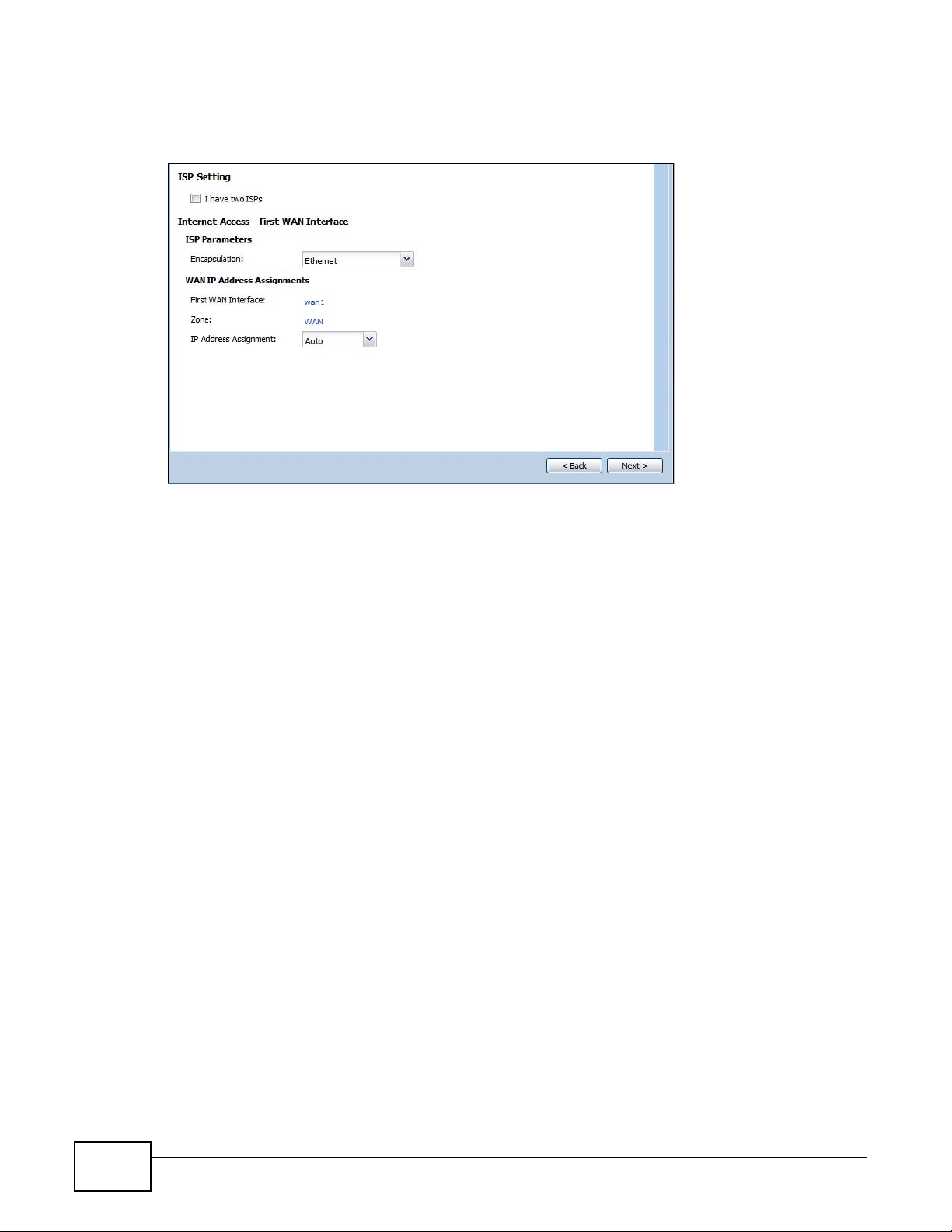
Chapter 4 Installation Setup Wizard
Note: Enter the Internet access information exactly as your ISP gave it to you.
Figure 36 Internet Access: Step 1
• I have two ISPs: Select this option to configure two Internet connections. Leave it cleared to
configure just one. This option appears when you are configuring the first WAN interface.
• Encapsulation: Choose the Ethernet option when the WAN port is used as a regular Ethernet.
Otherwise, choose PPP over Ethernet or PPTP for a dial-up connection according to the
information from your ISP.
• WAN Interface: This is the interface you are configuring for Internet access.
• Zone: This is the security zone to which this interface and Internet connection belong.
• IP Address Assignment: Select Auto if your ISP did not assign you a fixed IP address.
Select Static if the ISP assigned a fixed IP address.
4.1.2 Internet Access: Ethernet
This screen is read-only if you set the previous screen’s IP Address Assignment field to Auto.
Use this screen to configure your IP address settings.
60
ISG50 User’s Guide
Page 61

Chapter 4 Installation Setup Wizard
Note: Enter the Internet access information exactly as given to you by your ISP.
Figure 37 Internet Access: Ethernet Encapsulation
• Encapsulation: This displays the type of Internet connection you are configuring.
• First WAN Interface: This is the number of the interface that will connect with your ISP.
• Zone: This is the security zone to which this interface and Internet connection will belong.
• IP Address: Enter your (static) public IP address. Auto displays if you selected Auto as the IP
Address Assignment in the previous screen.
The following fields display if you selected static IP address assignment.
• IP Subnet Mask: Enter the subnet mask for this WAN connection's IP address.
• Gateway IP Address: Enter the IP address of the router through which this WAN connection
will send traffic (the default gateway).
• First / Second DNS Server: These fields display if you selected static IP address assignment.
The Domain Name System (DNS) maps a domain name to an IP address and vice versa. Enter a
DNS server's IP address(es). The DNS server is extremely important because without it, you
must know the IP address of a computer before you can access it. The ISG50 uses these (in the
order you specify here) to resolve domain names for VPN, DDNS and the time server. Leave the
field as 0.0.0.0 if you do not want to configure DNS servers.
ISG50 User’s Guide
61
Page 62

Chapter 4 Installation Setup Wizard
4.1.3 Internet Access: PPPoE
Note: Enter the Internet access information exactly as given to you by your ISP.
Figure 38 Internet Access: PPPoE Encapsulation
4.1.3.1 ISP Parameters
• T ype the PPPoE Se rvice Name from your service provider. PPPoE uses a service name to identify
and reach the PPPoE server. You can use alphanumeric and -_@$./ characters, and it can be up
to 64 characters long.
• Authentication Type - Select an authentication protocol for outgoing connection requests.
Options are:
• CHAP/PAP - Your ISG50 accepts either CHAP or PAP when requested by the remote node.
• CHAP - Your ISG50 accepts CHAP only.
• PAP - Your ISG50 accepts PAP only.
• MSCHAP - Your ISG50 accepts MSCHAP only.
• MSCHAP-V2 - Your ISG50 accepts MSCHAP-V2 only.
•Type the User Name given to you by your ISP. You can use alphanumeric and -_@$./ char acters,
and it can be up to 31 characters long.
•Type the Password associated with the user name. Use up to 64 ASCII characters except the []
and ?. This field can be blank.
•Select Nailed-Up if you do not want the connection to time out. Otherwise, type the Idle
Timeout in seconds that elapses before the router automatically disconnects from the PPPoE
server.
4.1.3.2 WAN IP Address Assignments
• WAN Interface: This is the name of the interface that will connect with your ISP.
• Zone: This is the security zone to which this interface and Internet connection will belong.
• IP Address: Enter your (static) public IP address. Auto displays if you selected Auto as the IP
Address Assignment in the previous screen.
62
ISG50 User’s Guide
Page 63

• First / Second DNS Server: These fields display if you selected static IP address assignment.
The Domain Name System (DNS) maps a domain name to an IP address and vice versa. Enter a
DNS server's IP address(es). The DNS server is extremely important because without it, you
must know the IP address of a computer before you can access it. The ISG50 uses these (in the
order you specify here) to resolve domain names for VPN, DDNS and the time server. Leave the
field as 0.0.0.0 if you do not want to configure DNS servers. If you do not configure a DNS server,
you must know the IP address of a machine in order to access it.
4.1.4 Internet Access: PPTP
Note: Enter the Internet access information exactly as given to you by your ISP.
Figure 39 Internet Access: PPTP Encapsulation
Chapter 4 Installation Setup Wizard
4.1.5 ISP Parameters
• Authentication Type - Select an authentication protocol for outgoing calls. Options are:
• CHAP/PAP - Your ISG50 accepts either CHAP or PAP when requested by the remote node.
• CHAP - Your ISG50 accepts CHAP only.
• PAP - Your ISG50 accepts PAP only.
• MSCHAP - Your ISG50 accepts MSCHAP only.
• MSCHAP-V2 - Your ISG50 accepts MSCHAP-V2 only.
•Type the User Name given to you by your ISP. You can use alphanumeric and -_@$./ char acters,
and it can be up to 31 characters long.
•Type the Password associated with the user name. Use up to 64 ASCII characters except the []
and ?. This field can be blank. Re-type your password in the next field to confirm it.
ISG50 User’s Guide
63
Page 64

Chapter 4 Installation Setup Wizard
•Select Nailed-Up if you do not want the connection to time out. Otherwise, type the Idle
Timeout in seconds that elapses before the router automatically disconnects from the PPTP
server.
4.1.5.1 PPTP Configuration
• Base Interface: This identifies the Ethernet interface you configure to connect with a modem or
router.
•Type a Base IP Address (static) assigned to you by your ISP.
• Type the IP Subnet Mask assigned to you by your ISP (if given).
• Server IP: Type the IP address of the PPTP server.
•Type a Connection ID or connection name. It must follow the “c:id” and “n:name” format. For
example, C:12 or N:My ISP. This field is optional and depends on the requirements of your
broadband modem or router. You can use alphanumeric and -_: characters, and it can be up to
31 characters long.
4.1.5.2 WAN IP Address Assignments
• First WAN Interface: This is the connection type on the interface you are configuring to
connect with your ISP.
• Zone This is the security zone to which this interface and Internet connection will belong.
• IP Address: Enter your (static) public IP address. Auto displays if you selected Auto as the IP
Address Assignment in the previous screen.
• First / Second DNS Server: These fields display if you selected static IP address assignment.
The Domain Name System (DNS) maps a domain name to an IP address and vice versa. Enter a
DNS server's IP address(es). The DNS server is extremely important because without it, you
must know the IP address of a computer before you can access it. The ISG50 uses these (in the
order you specify here) to resolve domain names for VPN, DDNS and the time server. Leave the
field as 0.0.0.0 if you do not want to configure DNS servers.
64
ISG50 User’s Guide
Page 65

4.1.6 Internet Access Setup - Second WAN Interface
If you selected I have two ISPs, after you configure the First WAN Interface, you can configure
the Second WAN Interface. The screens for configuring the second WAN interface are similar to
the first (see Section 4.1.1 on page 59).
Figure 40 Internet Access: Step 3: Second WAN Interface
Chapter 4 Installation Setup Wizard
ISG50 User’s Guide
65
Page 66

Chapter 4 Installation Setup Wizard
4.1.7 Internet Access - Finish
You ha ve set up your ISG50 to access the Internet. After configuring the W AN interface(s), a screen
displays with your settings. If they are not correct, click Back.
Figure 41 Internet Access: Ethernet Encapsulation
Note: If you h a ve not already done so, you can register your ISG50 with myZyXEL.com.
Click Next and use the following screen to perform a basic registration (see Section 4.2 on page
66). If you want to do a more detailed registration or manage your account details, click
myZyXEL.com.
Alternatively, close the window to exit the wizard.
4.2 Device Registration
Use this screen to register your ISG50 with myZXEL.com and activate trial periods of subscription
security features if you have not already done so. If the ISG50 is already registered this screen
displays your user name and which trial services are activated (if any). You can still activate any
un-activated trial services.
Note: You must be connected to the Internet to register.
66
ISG50 User’s Guide
Page 67

Chapter 4 Installation Setup Wizard
Use the Registration > Service screen to update your service subscription status.
Figure 42 Registration
•Select new myZyXEL.com account if you haven’t created an account at myZyXEL.com, select
this option and configure the following fields to create an account and register your ISG50.
•Select existing myZyXEL.com account if you already have an account at myZyXEL.com and
enter your user name and password in the fields below to register your ISG50.
•Enter a User Name for your myZyXEL.com account. Use from six to 20 alphanumeric characters
(and the underscore). Spaces are not allowed. Click Check to verify that it is available.
• Password: Use six to 20 alphanumeric characters (and the underscore). Spaces are not allowed.
Type it again in the Confirm Password field.
• E-Mail Address: Enter your e-mail address. Use up to 80 alphanumeric characters (periods and
the underscore are also allowed) without spaces.
ISG50 User’s Guide
67
Page 68

Chapter 4 Installation Setup Wizard
• Country Code: Select your country from the drop-down box list.
Figure 43 Registration: Registered Device
68
ISG50 User’s Guide
Page 69

5.1 Quick Setup Overview
The Web Configurator's quick setup wizards help y o u configu re Intern et and VPN connection
settings. This chapter provides information on configuring the quick setup screens in the Web
Configurator. See the feature-specific chapters in this User’s Guide for background information.
In the Web Configur ator, click Configuration > Quick Setup to open the first Quick Setup
screen.
Figure 44 Quick Setup
CHAPTER 5
Quick Setup
• WAN Interface
Click this link to open a wizard to set up a WAN (Internet) connection. This wizard creates
matching ISP account settings in the ISG50 if you use PPPoE or PPTP. See Section 5.2 on page
70.
• VPN SETUP
Use VPN SETUP to configure a VPN (Virtual Private Network) tunnel for a secure connection to
another computer, smartphone, or network. See Section 5.4 on page 77.
ISG50 User’s Guide 69
Page 70
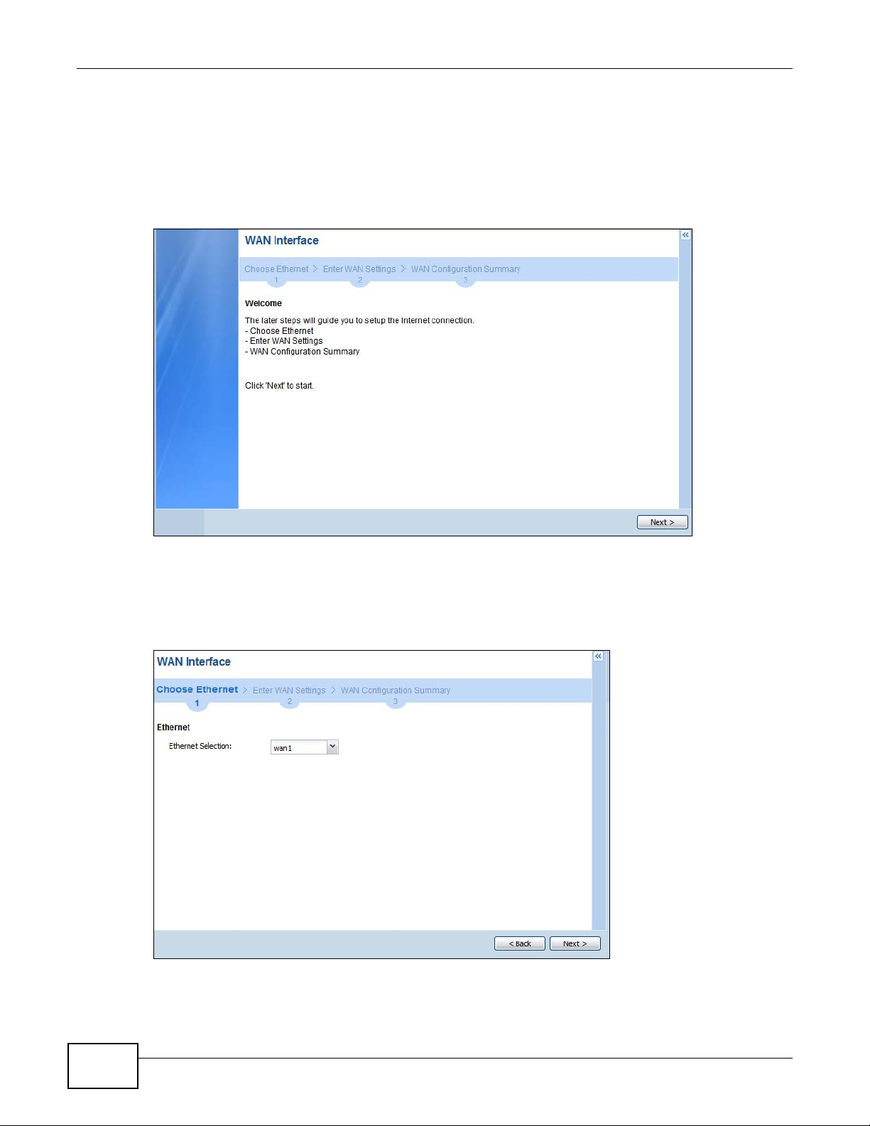
Chapter 5 Quick Setup
5.2 WAN Interface Quick Setup
Click WAN Interface in the main Quick Setup screen to open the WAN Interface Quick Setup
Wizard Welcome screen. Use these screens to configure an interface to connect to the internet.
Click Next.
Figure 45 WAN Interface Quick Setup Wizard
5.2.1 Choose an Ethernet Interface
Select the Ethernet interface that you want to configure for a WAN connection and click Next.
Figure 46 Choose an Ethernet Interface
70
ISG50 User’s Guide
Page 71

5.2.2 Select WAN Type
WAN Type Selection: Select the type of encapsulation this connection is to use. Choose Ethernet
when the WAN port is used as a regular Ethernet.
Otherwise, choose PPPoE or PPTP for a dial-up connection according to the information from your
ISP.
Figure 47 WAN Interface Setup: Step 2
Chapter 5 Quick Setup
The screens vary depending on what encapsulation type you use. Refer to information provided by
your ISP to know what to enter in each field. Leave a field blank if you don’t have that information.
Note: Enter the Internet access information exactly as your ISP gave it to you.
ISG50 User’s Guide
71
Page 72

Chapter 5 Quick Setup
5.2.3 Configure WAN Settings
Use this screen to select whether the interface should use a fixed or dynamic IP address.
Figure 48 WAN Interface Setup: Step 2
• WAN Interface: This is the interface you are configuring for Internet access.
• Zone: This is the security zone to which this interface and Internet connection belong.
• IP Address Assignment: Select Auto If your ISP did not assign you a fixed IP address.
Select Static If the ISP assigned a fixed IP address.
5.2.4 WAN and ISP Connection Settings
Use this screen to configure the ISP and WAN interface settings. This screen is read-only if you set
the IP Address Assignment to Static.
72
ISG50 User’s Guide
Page 73

Chapter 5 Quick Setup
Note: Enter the Internet access information exactly as your ISP gave it to you.
Figure 49 WAN and ISP Connection Settings: (PPTP Shown)
The following table describes the labels in this screen.
Table 11 WAN and ISP Connection Settings
LABEL DESCRIPTION
ISP Parameter This section appears if the interface uses a PPPoE or PPTP Internet connection.
Encapsulation This displays the type of Internet connection you are configuring.
ISG50 User’s Guide
Authentication
Type
User Name Type the user name given to you by your ISP. You can use alphanumeric and -_
Password Type the password associated with the user name above. Use up to 64 ASCII characters
Use the drop-down list box to select an authentication protocol for outgoing calls.
Options are:
CHAP/PAP - Your ISG50 accepts either CHAP or PAP when requested by this remote
node.
CHAP - Your ISG50 accepts CHAP only.
PAP - Your ISG50 accepts PAP only.
MSCHAP - Your ISG50 accepts MSCHAP only.
MSCHAP-V2 - Your ISG50 accepts MSCHAP-V2 only.
@$./
characters, and it can be up to 31 characters long.
except the [] and ?. This field can be blank.
73
Page 74

Chapter 5 Quick Setup
Table 11 WAN and ISP Connection Settings (continued)
LABEL DESCRIPTION
Retype to
Confirm
Nailed-Up Select Nailed-Up if you do not want the connection to time out.
Idle Timeout Type the time in seconds that elapses before the router automatically disconnects from
PPTP Configuration This section only appears if the interface uses a PPPoE or PPTP Internet connection.
Base Interface This displays the identity of the Ethernet interface you configure to connect with a
Base IP Address Type the (static) IP address assigned to you by your ISP.
IP Subnet Mask Type the subnet mask assigned to you by your ISP (if given).
Server IP Type the IP address of the PPTP server.
Connection ID Enter the connection ID or connection name in this field. It must follow the "c:id" and
Type your password again for confirmation.
the PPPoE server. 0 means no timeout.
modem or router.
"n:name" format. For example, C:12 or N:My ISP.
This field is optional and depends on the requirements of your DSL modem.
You can use alphanumeric and -_
WAN Interface
Setup
WAN Interface This displays the identity of the interface you configure to connect with your ISP.
Zone This field displays to which security zone this interface and Internet connection will
IP Address This field is read-only when the WAN interface uses a dynamic IP address. If your WAN
First DNS
Server
Second DNS
Server
Back Click Back to return to the previous screen.
Next Click Next to continue.
belong.
interface uses a static IP address, enter it in this field.
These fields only display for an interface with a static IP address. Enter the DNS server
IP address(es) in the field(s) to the right.
Leave the field as 0.0.0.0 if you do not want to configure DNS servers. If you do not
configure a DNS server, you must know the IP address of a machine in order to access
it.
DNS (Domain Name System) is for mapping a domain name to its corresponding IP
address and vice versa. The DNS server is extremely important because without it, you
must know the IP address of a computer before you can access it. The ISG50 uses a
system DNS server (in the order you specify here) to resolve domain names for VPN,
DDNS and the time server.
: characters, and it can be up to 31 characters long.
74
ISG50 User’s Guide
Page 75

5.2.5 Quick Setup Interface Wizard: Summary
This screen displays the WAN interface’s settings.
Figure 50 Interface Wizard: Summary WAN (PPTP Shown)
Chapter 5 Quick Setup
The following table describes the labels in this screen.
Table 12 Interface Wizard: Summary WAN
LABEL DESCRIPTION
Encapsulation This displays what encapsulation this interface uses to connect to the Internet.
Service Name This field is read-only and only appears for a PPPoE interface. It displays the PPPo E service
Server IP This field only appears for a PPTP interface. It displays the IP address of the PPTP server.
User Name This is the user name given to you by your ISP.
Nailed-Up If No displays the connection will not time out. Yes means the ISG50 uses the idle
Idle Timeout This is how many seconds the connection can be idle before the router automatically
Connection ID If you specified a connection ID, it displays here.
WAN Interface This identifies the interface you configure to connect with your ISP.
Zone This field displays to which security zone this interface and Internet connection will belong.
IP Address
Assignment
First DNS Server
Second DNS
Server
Close Click Close to exit the wizard.
name specified in the ISP account.
timeout.
disconnects from the PPPoE server. 0 means no timeout.
This field displays whether the WAN IP address is static or dynamic (Auto).
If the IP Address Assignment is Static, these fields display the DNS server IP
address(es).
ISG50 User’s Guide
75
Page 76

Chapter 5 Quick Setup
5.3 VPN Quick Setup
Click VPN Setup in the main Quick Setup screen to open the VPN Setup Wizard Welcome
screen. The VPN wizard creates corresponding VPN connection and VPN gateway settings and
address objects that you can use later in configuring more VPN connections or other features. Click
Next.
Figure 51 VPN Quick Setup Wizard
76
ISG50 User’s Guide
Page 77

5.4 VPN Setup Wizard: Wizard Type
A VPN (Virtual Private Network) tunnel is a secure connection to another computer, smartphone, or
network. Use this screen to select which type of VPN connection you want to configure.
Figure 52 VPN Setup Wizard: Wizard Type
Chapter 5 Quick Setup
Express: Use this wizard to create a VPN connection with another ISG50 using a pre-shared key
and default security settings.
Advanced: Use this wizard to configure detailed VPN security settings such as using certificates.
The VPN connection can be to another ISG50 or other IPSec device.
ISG50 User’s Guide
77
Page 78

Chapter 5 Quick Setup
5.5 VPN Express Wizard - Scenario
Click the Express radio button as shown in Figure 52 on page 77 to display the following screen.
Figure 53 VPN Express Wizard: Step 2
Rule Name: Type the name used to identify this VPN connection (and VPN gateway). Y ou may use
1-31 alphanumeric characters, underscores (_), or dashes (-), but the first character cannot be a
number. This value is case-sensitive.
Select the scenario that best describes your intended VPN connection. The figure on the left of the
screen changes to match the scenario you select.
• Site-to-site - Choose this if the remote IPSec device has a static IP address or a domain name.
This ISG50 can initiate the VPN tunnel.
• Site-to-site with Dynamic Peer - Choose this if the remote IPSec device has a dynamic IP
address. Only the remote IPSec device can initiate the VPN tunnel.
• Remote Access (Server Role) - Choose this to allow incoming connections from IPSec VPN clients,
including smartphone applications. The clients have dynamic IP addresses and are also known as
dial-in users. Only the clients can initiate the VPN tunnel.
• Remote Access (Client Role) - Choose this to connect to an IPSec server. This ISG50 is the client
(dial-in user) and can initiate the VPN tunnel.
See Application Scenarios on page 369 for more on the scenarios.
78
ISG50 User’s Guide
Page 79

5.5.1 VPN Express Wizard - Configuration
Figure 54 VPN Express Wizard: Step 3
Chapter 5 Quick Setup
• Secure Gateway: If Any displays in this field, it is not configurable for the chosen scenario. If
this field is configurable, enter the WAN IP address or domain name of the remote IPSec device
(secure gateway) to identify the remote IPSec router by its IP address or a domain name. Use
0.0.0.0 if the remote IPSec router has a dynamic WAN IP address.
• Pre-Shared Key: T ype the password. Both ends of the VPN tunnel must use the same password.
Use 8 to 31 case-sensitive ASCII characters or 8 to 31 pairs of hexadecimal (“0-9”, “A-F”)
characters. Proceed a hexadecimal key with “0x”. You will receive a PYLD_MALFORMED (payload
malformed) packet if the same pre-shared key is not used on both ends.
• Local Policy (IP/Mask): Type the IP address of a computer on your network. You can also
specify a subnet. This must match the remote IP address configured on the remote IPSec device.
• Remote Policy (IP/Mask): If Any displays in this field, it is not configurable for the chosen
scenario. If this field is configurable, type the IP address of a computer behind the remote IPSec
device. You can also specify a subnet. This must match the local IP address configured on the
remote IPSec device.
ISG50 User’s Guide
79
Page 80

Chapter 5 Quick Setup
5.5.2 VPN Express Wizard - Summary
This screen provides a read-only summary of the VPN tunnel’s configuration and also commands
that you can copy and paste into another ISG50’s command line interface to configure it.
Figure 55 VPN Express Wizard: Step 4
• Rule Name: Identifies the VPN gateway policy.
• Secure Gateway: IP address or domain name of the remote IPSec device. If this field displays
Any, only the remote IPSec device can initiate the VPN connection.
• Pre-Shared Key: VPN tunnel password. It identifies a communicating party during a phase 1
IKE negotiation.
• Local Policy: (Static) IP address and subnet mask of the computers on the network behind y our
ISG50 that can use the tunnel.
• Remote Policy: (Static) IP address and subnet mask of the computers on the network behind
the remote IPSec device that can use the tunnel. If this field displays Any, only the remote IPSec
device can initiate the VPN connection.
• Copy and paste the Configuration for Secure Gateway commands into another ISG50’s
command line interface to configure it to serve as the other end of this VPN tunnel. You can also
use a text editor to save these commands as a shell script file with a “.zysh” filename extension.
Then you can use the file manager to run the script in order to configure the VPN connection. See
the commands reference guide for details on the commands displayed in this list.
80
ISG50 User’s Guide
Page 81

5.5.3 VPN Express Wizard - Finish
Now you can use the VPN tunnel.
Figure 56 VPN Express Wizard: Finish
Chapter 5 Quick Setup
Note: If you have not already done so, use the myZyXEL.com link and register your
ISG50 with myZyXEL.com.
Click Close to exit the wizard.
ISG50 User’s Guide
81
Page 82

Chapter 5 Quick Setup
5.5.4 VPN Advanced Wizard - Scenario
Click the Advanced radio button as shown in Figure 52 on page 77 to display the following screen.
Figure 57 VPN Advanced Wizard: Scenario
Rule Name: Type the name used to identify this VPN connection (and VPN gateway). Y ou may use
1-31 alphanumeric characters, underscores (_), or dashes (-), but the first character cannot be a
number. This value is case-sensitive.
Select the scenario that best describes your intended VPN connection. The figure on the left of the
screen changes to match the scenario you select.
• Site-to-site - Choose this if the remote IPSec device has a static IP address or a domain name.
This ISG50 can initiate the VPN tunnel.
• Site-to-site with Dynamic Peer - Choose this if the remote IPSec device has a dynamic IP
address. Only the remote IPSec device can initiate the VPN tunnel.
• Remote Access (Server Role) - Choose this to allow incoming connections from IPSec VPN clients.
The clients have dynamic IP addresses and are also known as dial-in users. Only the clients can
initiate the VPN tunnel.
• Remote Access (Client Role) - Choose this to connect to an IPSec server. This ISG50 is the client
(dial-in user) and can initiate the VPN tunnel.
82
ISG50 User’s Guide
Page 83

5.5.5 VPN Advanced Wizard - Phase 1 Settings
There are two phases to every IKE (Internet Key Exchange) negotiation – phase 1 (Authentication)
and phase 2 (Key Exchange). A phase 1 exchange establishes an IKE SA (Security Association).
Figure 58 VPN Advanced Wizard: Phase 1 Settings
Chapter 5 Quick Setup
• Secure Gateway: If Any displays in this field, it is not configurable for the chosen scenario. If
this field is configurable, enter the WAN IP address or domain name of the remote IPSec device
(secure gateway) to identify the remote IPSec device by its IP address or a domain name. Use
0.0.0.0 if the remote IPSec device has a dynamic WAN IP address.
• My Address (interface): Select an interface from the drop-down list box to use on your ISG50.
• Negotiation Mode: Select Main for identity protection. Select Aggressive to allow more
incoming connections from dynamic IP addresses to use separate passwords.
Note: Multiple SAs connecting through a secure gateway mus t have the same negotiation
mode.
• Encryption Algorithm: 3DES and AES use encryption. The longer the key, the higher the
security (this may affect throughput). Both sender and receiver must know the same secret key,
which can be used to encrypt and decrypt the message or to generate and verify a message
authentication code. The DES encryption algorithm uses a 56-bit key. Triple DES (3DES) is a
variation on DES that uses a 168-bit key. As a result, 3DES is more secure than DES. It also
requires more processing power, resulting in increased latency and decreased throughput.
AES128 uses a 128-bit key and is faster than 3DES. AES192 uses a 192-bit key and AES256 uses
a 256-bit key.
• Authentication Algorithm: MD5 gives minimal security . SHA-1 gives higher security. MD5
(Message Digest 5) and SHA1 (Secure Hash Algorithm) are hash algorithms used to authenticate
packet data. The SHA1 algorithm is generally considered stronger than MD5, but is slower.
• Key Group: DH5 is more secure than DH1 or DH2 (although it may affect throughput). DH1
(default) refers to Diffie-Hellman Group 1 a 768 bit random number. DH2 refers to Diffie-Hellman
Group 2 a 1024 bit (1Kb) random number. DH5 refers to Diffie-Hellman Group 5 a 1536 bit
random number.
ISG50 User’s Guide
83
Page 84

Chapter 5 Quick Setup
• SA Life Time: Set how often the ISG50 renegotiates the IKE SA. A short SA life time increases
security, but renegotiation temporarily disconnects the VPN tunnel.
• NAT Traversal: Select this if the VPN tunnel must pass through NAT (there is a NAT router
between the IPSec devices).
Note: The remote IPSec device must also have NAT traversal enabled. See the help in the
main IPSec VPN screens or the User’s Guide VPN, NAT, and NA T Traversal on page
390 for more information.
• Dead Peer Detection (DPD) has the ISG50 make sure the remote IPSec device is there before
transmitting data through the IKE SA. If there has been no traffic for at least 15 seconds, the
ISG50 sends a message to the remote IPSec device. If it responds, the ISG50 transmits the data.
If it does not respond, the ISG50 shuts down the IKE SA.
• Authentication Method: Select Pre-Shared Key to use a password or Certificate to use one
of the ISG50’s certificates.
5.5.6 VPN Advanced Wizard - Phase 2
Phase 2 in an IKE uses the SA that was established in phase 1 to negotiate SAs for IPSec.
Figure 59 VPN Advanced Wizard: Step 4
84
• Active Protocol: ESP is compatible with NAT, AH is not.
• Encapsulation: Tunnel is compatible with NAT, Transport is not.
• Encryption Algorithm: 3DES and AES use encryption. The longer the AES key, the higher the
security (this may affect throughput). Null uses no encryption.
• Authentication Algorithm: MD5 gives minimal security . SHA-1 gives higher security. MD5
(Message Digest 5) and SHA1 (Secure Hash Algorithm) are hash algorithms used to authenticate
packet data. The SHA1 algorithm is generally considered stronger than MD5, but is slower.
• SA Life Time: Set how often the ISG50 renegotiates the IKE SA. A short SA life time increases
security, but renegotiation temporarily disconnects the VPN tunnel.
ISG50 User’s Guide
Page 85

• Perfect Forward Secrecy (PFS): Disabling PFS allows faster IPSec setup, but is less secure. Select
DH1, DH2 or DH5 to enable PFS. DH5 is more secure than DH1 or DH2 (although it may affect
throughput). DH1 refers to Diffie-Hellman Group 1 a 768 bit random number. DH2 refers to
Diffie-Hellman Group 2 a 1024 bit (1Kb) random number. DH5 refers to Diffie-Hellman Group 5 a
1536 bit random number (more secure, yet slower).
• Local Policy (IP/Mask): Type the IP address of a computer on your network. You can also
specify a subnet. This must match the remote IP address configured on the remote IPSec device.
• Remote Policy (IP/Mask): T ype the IP address of a computer behind the remote IPSec device.
You can also specify a subnet. This must match the local IP address configured on the remote
IPSec device.
• Nailed-Up: This displays for the site-to-site and remote access client role scenarios. Select this
to have the ISG50 automatically renegotiate the IPSec SA when the SA life time expires.
5.5.7 VPN Advanced Wizard - Summary
This is a read-only summary of the VPN tunnel settings.
Figure 60 VPN Advanced Wizard: Step 5
Chapter 5 Quick Setup
• Rule Name: Identifies the VPN connection (and the VPN gateway).
• Secure Gateway: IP address or domain name of the remote IPSec device.
• Pre-Shared Key: VPN tunnel password.
• Certificate: The certificate the ISG50 uses to identify itself when setting up the VPN tunnel.
• Local Policy: IP address and subnet mask of the computers on the network behind your ISG50
that can use the tunnel.
• Remote Policy: IP address and subnet mask of the computers on the network behind the
remote IPSec device that can use the tunnel.
• Copy and paste the Configuration for Remote Gateway commands into another ISG50’s
command line interface.
• Click Save to save the VPN rule.
ISG50 User’s Guide
85
Page 86

Chapter 5 Quick Setup
5.5.8 VPN Advanced Wizard - Finish
Now you can use the VPN tunnel.
Figure 61 VPN Wizard: Step 6: Advanced
86
Note: If you h a ve not already done so, you can register your ISG50 with myZyXEL.com
and activate trials of services.
Click Close to exit the wizard.
ISG50 User’s Guide
Page 87

CHAPTER 6
Configuration Basics
This information is provided to help you configure the ISG50 effectively . Some of it is helpful when
you are just getting started. Some of it is provided for your reference when you configure various
features in the ISG50.
• Section 6.2 on page 91 introduces the ISG50’s object-based configuration.
• Section 6.3 on page 92 introduces zones, interfaces, and port groups.
• Section 6.4 on page 94 introduces some terminology and organization for the ISG50.
• Section 6.5 on page 94 covers the ISG50’s packet flow.
• Section 6.6 on page 97 identifies the features you should configure before and after you
configure the main screens for each feature. For example, if you want to configure a trunk for
load-balancing, you should configure the member interfaces before you configure the trunk. After
you configure the trunk, you should configure a policy route for it as well. (Y ou might also have to
configure criteria for the policy route.)
• Section 6.7 on page 103 identifies the objects that store information used by other features.
• Section 6.8 on page 104 introduces some of the tools available for system management.
6.1 PBX Features Overview
This chapter is an overview of different logical components and how they work together to route
calls on the ISG50.
6.1.1 Call Routing
The two main functions of any IP-PBX are routing internal calls and handling calls to and from the
outside world.
The following sections explain how these functions are performed on the ISG50.
6.1.1.1 Call Routing Terms
The following are some terms related to ZyXEL’s IP-PBX implementation.
• Extension - This is a unique number assigned to each telephone connected to the ISG50.
Extensions are used to make calls between phones connected to the ISG50 and to route calls
from the outside world to their correct target. Extensions fall into the following two groups:
• SIP Extension - This is an extension assigned to a SIP (Session Initiation Protocol) based IP
phone connected to the ISG50. Alternatively this could be an extension assigned to an analog
phone which connects to the ISG50 via a VoIP gateway device.
ISG50 User’s Guide 87
Page 88

Chapter 6 Configuration Basics
FXO
FXO
FXS
FXS
PSTN
ISG
• FXS (Foreign Exchange Subscriber) Extension - This is an extension assigned to an analog
phone directly connected to an FXS port on the ISG50 (See Figure 62 on page 88). The FXS
ports on the ISG50 work the same way as the phone sockets in your home. In your home you
are a subscriber to the telephone services of your local telephone company and when you
connect an analog phone to the ISG50 you subscribe to the telephone services of the ISG50.
• Authority Group - This is a set of extensions. Each extension can only belong to one authority
group. Authority groups manage extensions by allowing them to make only certain types of calls.
For example, if you create two authority groups, y ou can allow one group to mak e local calls and
long distance calls and the second authority group to make local calls only.
• Outbound Line Group - This is a set of connections or lines going to the outside world.
• SIP Trunk - This is a connection to your ITSP (Internet Telephony Service Provider).
• ISDN BRI Trunk - This is a connection to your ISDN Service Provider.
• Trusted Peer - This is a connection to another IP PBX or SIP server. The trusted peer device
must also specify your ISG50 as a trusted peer.
• FXO (Foreign Exchange Office) Trunk - This type of outbound line group consists of
telephone cables connected to FXO ports on the ISG50. The telephone cables lead to the PSTN
(Public Switched Telephone Network), or in other words your traditional (non-VoIP) telephone
company. FXO ports always point in the direction of the telephone services.
The figure below shows the relationship between FXS and FXO ports.
Figure 62 FXS and FXO Ports
88
• LCR (Least Cost Routing) - This is a rule which specifies which outbound line group is used
when making an outbound call. It consists of a dialing condition, for example dial 0 to make a call
via a specific FXO trunk or dial 1 for calls via a SIP trunk. LCRs also set priority to which
outbound line group should be tried first, second, third and so on when making outbound calls
with the same dialing condition.
ISG50 User’s Guide
Page 89

Chapter 6 Configuration Basics
AA1
FAX
1001
1002
1003
2001
555-0001
555-0002
Please dial the
extension you
would like to
reach.
ISG
• Auto-Attendant - This is a feature which routes incoming calls to their proper extension. An
auto-attendant is assigned to each outbound line group and it services incoming calls on those
lines. If your organization has two outbound line groups, each with a specific telephone number
for incoming calls, then you can assign a different auto-attendant for each incoming line. Assign
one auto-attendant for general calls to the extensions in your organization (for example AA1)
and one auto-attendant for direct routing to a FAX machine (for example FAX).
Figure 63 Auto-Attendant
6.1.2 Internal Call Routing
Internal call routing refers to calls between extensions on the ISG50. People simply dial the
extension they want to call. The ISG50 checks to see if the number dialed is an existing extension
and forwards the call to that extension. The ISG50 by default allows people with extensions from
one authority group to call extensions in another authority group. You can, however, block calls
between authority groups if your organization requires such a setting.
The configuration requirement for setting up internal call routing are:
1 Create an authority group.
2 Create extensions in the authority group.
6.1.3 Outbound Call Routing
Outbound call routing refers to calls originating from an extension on the ISG50, going via an
outbound line group to a telephone outside your organization. Outbound call routing requires that
an authority group is linked to an outbound line group. The link between the two is an LCR (Least
Cost Routing). LCRs contain the dialing rules for outbound line groups. Authority groups need to be
associated to LCRs to gain access to the outbound line groups.
ISG50 User’s Guide
89
Page 90

Chapter 6 Configuration Basics
Authority
Group
Outbound
Line Group
LCR
Authority
Group
Authority
Group
Outbound
Line Group
LCR - Local
LCR - Long Distance
LCR - Local
Sales
R&D
In the most basic setup example an organization has one authority group (with all of the company’s
extensions), one outbound line group and an LCR which grants the authority group access to
outbound lines. Everyone in the organization has the same rights to use outbound lines.
Figure 64 Outbound Call Routing - Basic
In a more advanced example, you can create two authority groups, still have one outbound line
group and two different LCRs. You can now control the t ypes of outbound calls that can be made by
each authority group.
In the figure below, the SALES authority group has a local call LCR and a long distance LCR
associated to it. This allows its group members to make both local and long distance calls via the
outbound line group. R&D authority group only has the local LCR associated to it so its group
members can only make local calls via the outbound line group.
Figure 65 Outbound Call Routing - Advanced
The configuration requirement for setting up outbound call routing are:
1 Create an authority group.
2 Create extensions in the authority group.
3 Create an outbound line group.
4 Create LCRs and add outbound line groups to them.
5 Associate LCRs to authority groups.
90
ISG50 User’s Guide
Page 91

6.2 Object-based Configuration
The ISG50 stores information or settings as objects. You use these objects to configure many of the
ISG50’s features and settings. Once you configure an object, you can reuse it in configuring other
features.
When you change an object’s settings, the ISG50 automatically updates all the settings or rules
that use the object. For example, if you create a schedule object, you can have firewall and other
settings use it. If you modify the schedule, all the firewall and other settings that use the schedule
automatically apply the updated schedule.
You can create address objects based on an interface’s IP address, subnet, or gateway. The ISG50
automatically updates every rule or setting that uses these objects whenever the interface’s IP
address settings change. For example, if you change an Ethernet interface’s IP address, the ISG50
automatically updates the rules or settings that use the interface-based, LAN subnet address
object.
You can use the Configuration > Objects screens to create objects before you configure features
that use them. If you are in a screen that uses objects, you can also usually select Create new
Object to be able to configure a new object. For a list of common objects, see Section 6.7 on page
103.
Chapter 6 Configuration Basics
Use the Object Reference screen (Section 3.3.3.3 on page 53) to see what objects are configured
and which configuration settings reference specific objects.
ISG50 User’s Guide
91
Page 92

Chapter 6 Configuration Basics
Physical Ports
Interfaces
Zones
DMZ
dmz
LAN2
lan2
WAN
wan1 wan2
LAN1
lan1
6.3 Zones, Interfaces, and Physical Ports
Zones (groups of interfaces and VPN tunnels) simplify security settings. Here is an overview of
zones, interfaces, and physical ports in the ISG50.
Figure 66 Zones, Interfaces, and Physical Ethernet Ports
Table 13 Zones, Interfaces, and Physical Ethernet Ports
Zones
(WAN,LAN, DMZ)
Interfaces
(Ethernet, VLAN,...)
Physical Ethernet
Ports
(P1, P2, ...)
A zone is a group of interfaces and VPN tunnels. Use zones to apply securit y settings
such as firewall, and remote management.
Interfaces are logical entities that (layer-3) packets pass through. Use interfaces in
configuring VPN, zones, trunks, DDNS, policy routes, static routes, HTTP redirect,
and NAT.
Port roles combine physical ports into interfaces.
The physical port is where you connect a cable. In configuration, you use physical
ports when configuring port groups. You use interfaces and zones in configuring
other features.
6.3.1 Interface Types
92
There are many types of interfaces in the ISG50. In addition to being used in various features,
interfaces also describe the network that is directly connected to the ISG50.
• Ethernet interfaces are the foundation for defining other interfaces and network policies. You
also configure RIP and OSPF in these interfaces.
• Port groups create a hardware connection between physical ports at the layer-2 (data link, MAC
address) level. Port groups are created when you use the Interface > Port Roles screen to set
multiple physical ports to be part of the same (lan1, lan2 or dmz) interface.
• PPP interfaces support Point-to-Point Protocols (PPPoE or PPTP). ISP accounts are required for
PPPoE/PPTP interfaces.
• VLAN interfaces recognize tagged frames. The ISG50 automatically adds or removes the tags
as needed. Each VLAN can only be associated with one Ethernet interface.
• Bridge interfaces create a software connection between Ethernet or VLAN interfaces at the
layer-2 (data link, MAC address) level. Then, you can configure the IP address and subnet mask
of the bridge. It is also possible to configure zone-level security between the member interfaces
in the bridge.
ISG50 User’s Guide
Page 93

• Virtual interfaces increase the amount of routing information in the ISG50. There are three
types: virtual Ethernet interfaces (also known as IP alias), virtual VLAN interfaces, and
virtual bridge interfaces.
6.3.2 Default Interface and Zone Configuration
This section introduces the ISG50’s default zone member physical interfaces and the default
configuration of those interfaces. The following figure uses letters to denote public IP addresses or
part of a private IP address.
Figure 67 Default Network Topology
Chapter 6 Configuration Basics
Table 14 ISG50 Default Port, Interface, and Zone Configuration
PORT INTERFACE ZONE IP ADDRESS AND DHCP SETTINGS
P1, P2 wan1, wan2 WAN DHCP clients Connections to the Internet
P3 lan1 LAN1 192.168.1.1, DHCP server enabled Protected LAN
P4 lan2 LAN2 192.168.2.1, DHCP server enabled Protected LAN
P5 dmz DMZ 192.168.3.1, DHCP server disabled Public servers (such as web, e-
CONSOLE n/a None None Local management
• The WAN zone contains the wan1 and wan2 interfaces (physical ports P1 and P2). They use
public IP addresses to connect to the Internet.
• The LAN1 zone contains the lan1 interface (physical port P3). The LAN1 zone is a protected
zone. The lan1 interface uses 192.168.1.1 and the connected devices use IP addresses in the
192.168.1.2 to 192.168.1.254 range.
• The LAN2 zone contains the lan2 interface (physical port P4). The LAN2 zone is a protected
zone. The lan2 interface uses 192.168.2.1 and the connected devices use IP addresses in the
192.168.2.2 to 192.168.2.254 range.
• The DMZ zone contains the dmz interface (physical port P5). The DMZ zone has servers that are
available to the public. The dmz interface uses private IP address 192.168.3.1 and the connected
devices use private IP addresses in the 192.168.3.2 to 192.168.3.254 range.
SUGGESTED USE WITH
DEFAULT SETTINGS
mail and FTP)
ISG50 User’s Guide
93
Page 94

Chapter 6 Configuration Basics
Traffic Out
Defragment ALG DNAT Routing
Forwarding Engine
Network
I/O Engine
Stateful Firewall
ADP (PA/TA)
Application Classifier
SNAT BWM
Traffic In
6.4 Terminology in the ISG50
This section highlights some terminology or organization for the ISG50.
Table 15 ISG50 Terminology
FEATURE / TERM ISG50 FEATURE / TERM
IP alias Virtual interface
Gateway policy VPN gateway
Network policy (IPSec SA) VPN connection
Source NAT (SNAT) Policy route
Trigger port, port triggering Policy route
Address mapping Policy route
Address mapping (VPN) IPSec VPN
Interface bandwidth management
(outbound)
General bandwidth management Policy route
Interface
6.5 Packet Flow
Here is the order in which the ISG50 applies its features and checks.
Traffic in > Defragmentation > Destination NAT > Routing > Stateful Firewall > ADP > SNAT >
Bandwidth Management > Fragmentation > Traffic Out.
Figure 68 Packet Flow
The packet flow is as follows:
94
ISG50 User’s Guide
Page 95

• Automatic SNAT and WAN trunk routing for traffic going from internal to external interfaces (you
don’t need to configure anything to all LAN to WAN traffic).
The ISG50 automatically adds all of the external interfaces to the default WAN trunk. External
interfaces include ppp and cellular interfaces as well as any Ethernet interfaces that are set as
external interfaces.
Examples of internal interfaces are any Ethernet interfaces that you configure as internal
interfaces.
• A policy route can be automatically disabled if the next-hop is dead.
• You do not need to set up policy routes for IPSec traffic.
• Policy routes can override direct routes.
• You do not need to set up policy routes for 1:1 NAT entries.
• You can create Man y 1:1 NA T entries to tr anslate a range of private networ k addresses to a range
of public IP addresses
• Static and dynamic routes have their own category.
6.5.1 Routing Table Checking Flow
When the ISG50 receives pack e t s it de fragments them and applies destination NAT. Then it
examines the packets and determines how to route them. The checking flow is from top to bottom.
As soon as the packets match an entry in one of the sections, the ISG50 stops checking the packets
against the routing table and moves on to the other checks, for example the firewall check.
Chapter 6 Configuration Basics
Figure 69 Routing Table Checking Flow
1 Direct-connected Subnets: The ISG50 first checks to see if the packets are destined for an
address in the same subnet as one of the ISG50’s interfaces. You can override this and have the
ISG50 check the policy routes first by enabling the policy route feature’s Use Policy Route to
Override Direct Route option (see Section 14.1 on page 289).
ISG50 User’s Guide
95
Page 96

Chapter 6 Configuration Basics
2 Policy Routes: These are the user-configured policy routes. Configure policy routes to send
packets through the appropriate interface or VPN tunnel. See Chapter 14 on page 289 for more on
policy routes.
3 1 to 1 and Many 1 to 1 NAT: These are the 1 to 1 NAT and many 1 to 1 NAT rules. If a private
network server will initiate sessions to the outside clients, create a 1 to 1 NAT entry to have the
ISG50 translate the source IP address of the server’s outgoing tr affic to the same public IP address
that the outside clients use to access the server . A many 1 to 1 NAT entry works like multiple 1 to 1
NAT rules. It maps a range of private network servers that will initiate sessions to the outside
clients to a range of public IP addresses. See Section 18.2.1 on page 325 for more.
4 Auto VPN Policy: The ISG50 automatically creates these routing entries for the VPN rules.
Disabling the IPSec VPN feature’s Use Policy Route to control dynamic IPSec rules option
moves the routes for dynamic IPSec rules up above the policy routes (see Section 24.2 on page
370).
5 Static and Dynamic Routes: This section contains the user-configured static routes and the
dynamic routing information learned from other routers through RIP and OSPF. See Chapter 14 on
page 289 for more information.
6 Default WAN Trunk: For any traffic coming in through an internal interface, if it does not match
any of the other routing entries, the ISG50 forwards it through the default WAN trunk. See Section
13.2 on page 285 for how to select which trunk the ISG50 uses as the default.
7 Main Routing Table: The default WAN trunk is expected to be used for any traffic that did not
match any earlier routing entries.
6.5.2 NAT Table Checking Flow
The checking flow is from top to bottom. As soon as the packets match an entry in one of the
sections, the ISG50 stops checking the packets against the NAT table and moves on to bandwidth
management.
Figure 70 NAT Table Checking Flow
96
ISG50 User’s Guide
Page 97

1 SNAT defined in the policy routes.
2 1 to 1 SNAT (including Many 1 to 1) is also included in the NAT table.
3 NAT loopback is now included in the NAT table instead of requiring a separate policy route.
4 SNAT is also now performed by default and included in the NAT table.
6.6 Other Features Configuration Overview
This section provides information about configuring the main features in the ISG50. The features
are listed in the same sequence as the menu item(s) in the Web Configurator. Each feature
description is organized as shown below.
6.6.1 Feature
This provides a brief description. See the appropriate chapter(s) in this User’s Guide for more
information about any feature.
Chapter 6 Configuration Basics
This shows you the sequence of menu items and tabs you should click to find the main
MENU ITEM(S)
PREREQUISITES
WHERE USED
Example: This provides a simple example to show you how to configure this feature. The example
is usually based on the network topology in Figure 67 on page 93.
screen(s) for this feature. See the web help or the related User’s Guide chapter for
information about each screen.
These are other features you should configure before you configure the main screen(s)
for this feature.
If you did not configure one of the prerequisites first, you can often sel ect an option to
create a new object. After you create the object you return to the main screen to finish
configuring the feature.
You may not have to configure everything in the list of prerequisites. For example, you
do not have to create a schedule for a policy route unless time is one of the criterion.
There are two uses for this.
These are other features you s hould us uall y configure or check right after you configure
the main screen(s) for this feature. For example, you should usually create a policy
route for a VPN tunnel.
You ha ve to de lete the re ferences to this fe ature before you can delete any settings. For
example, you have to delete (or modify) all the policy routes that refer to a VPN tunnel
before you can delete the VPN tunnel.
Note: PREQUISITES or WHERE USED does not appear if there are no prerequisites or
references in other features to this one. For example, no other features reference
DDNS entries, so there is no WHERE USED entry.
ISG50 User’s Guide
97
Page 98

Chapter 6 Configuration Basics
6.6.2 Licensing Registration
Use these screens to register your ISG50 and subscribe to services. Y ou must hav e Internet access
to myZyXEL.com.
MENU ITEM(S)
PREREQUISITES
6.6.3 Interface
See Section 6.3 on page 92 for background information.
Note: When you create an interface, there is no security applied on it until you assign it to
a zone.
Most of the features that use interfaces support Ethernet, PPPoE/PPTP, cellular, VLAN, and bridge
interfaces.
MENU ITEM(S)
PREREQUISITES
WHERE USED
Example: The dmz interface is in the DMZ zone and uses a private IP address. To configure dmz’s
settings, click Network > Interface > Ethernet and then the dmz’s Edit icon.
6.6.4 Trunks
Configuration > Licensing > Registration
Internet access to myZyXEL.com
Configuration > Network > Interface (except Network > Interface >
Trunk)
Port groups (configured in the Interface > Port Grouping screen)
Zones, trunks, IPSec VPN, DDNS, policy routes, static routes, HTTP redirect, NAT
Use trunks to set up load balancing using two or more interfaces.
MENU ITEM(S)
PREREQUISITES
WHERE USED
Example: See Chapter 7 on page 107.
6.6.5 Policy Routes
Use policy routes to override the ISG50’s default routing behavior in order to send packets through
the appropriate interface or VPN tunnel. You can also use policy routes for bandwidth management
(out of the ISG50), port triggering, and general NAT on the source address. You have to set up the
criteria, next-hops, and NAT settings first.
MENU ITEM(S)
Configuration > Network > Interface > Trunk
Interfaces
Policy routes
Configuration > Network > Routing > Policy Route
98
ISG50 User’s Guide
Page 99

Chapter 6 Configuration Basics
Criteria: users, user groups, interfaces (incoming), IPSec VPN (incoming),
addresses (source, destination), address groups (source, destination),
schedules, services, service groups
PREREQUISITES
Example: You have an FTP server connected to P6 (in the DMZ zone). You want to limit the
amount of FTP traffic that goes out from the FTP server through your WAN connection.
1 Create an address object for the FTP server (Object > Address).
2 Click Configuration > Network > Routing > Policy Route to go to the policy route
configuration screen. Add a policy route.
3 Name the policy route.
4 Select the interface that the traffic comes in through (P3 in this example).
5 Select the FTP server’s address as the source address.
Next-hop: addresses (HOST gateway), IPSec VPN, trunks, interfaces
NAT: addresses (translated address), services and service groups (port
triggering)
6 You don’t need to specify the destination address or the schedule.
7 For the service, select FTP.
8 For the Next Hop fields, select Interface as the Type if you have a single WAN connection or
Trunk if you have multiple WAN connections.
9 Select the interface that you are using for your WAN connection (wan1 and wan2 are the default
WAN interfaces). If you have multiple WAN connections, select the trunk.
10 Specify the amount of bandwidth FTP traffic can use. You may also want to set a low
priority for FTP traffic.
Note: The ISG50 checks the polic y r out es in t he or der that th ey are l ist ed . So make sure
that your custom policy route comes before any other routes that would also match
the FTP traffic.
6.6.6 Static Routes
Use static routes to tell the ISG50 about networks not directly connected to the ISG50.
MENU ITEM(S)
PREREQUISITES
Configuration > Network > Routing > Static Route
Interfaces
6.6.7 Zones
See Section 6.3 on page 92 for background information. A zone is a group of interfaces and VPN
tunnels. The ISG50 uses zones, not interfaces, in many security settings, such as firewall rules and
remote management.
ISG50 User’s Guide
99
Page 100

Chapter 6 Configuration Basics
Zones cannot overlap. Each interface and VPN tunnel can be assigned to at most one zone. Virtual
interfaces are automatically assigned to the same zone as the interface on which they run. When
you create a zone, the ISG50 does not create any firewall rule or configure remote management for
the new zone.
MENU ITEM(S)
PREREQUISITES
WHERE USED
Example: For example, to create the DMZ-2 zone, click Network > Zone and then the Add icon.
6.6.8 DDNS
Dynamic DNS maps a domain name to a dynamic IP address. The ISG50 helps maintain this
mapping.
MENU ITEM(S)
PREREQUISITES
6.6.9 NAT
Use Network Address Translation (NA T) to make computers on a priv ate network behind the ISG50
available outside the private network.
The ISG50 only checks regular (through-ISG50) firewall rules for packets that are redirected by
NAT, it does not check the to-ISG50 firewall rules.
Configuration > Network > Zone
Interfaces, IPSec VPN
Firewall, remote management, ADP
Configuration > Network > DDNS
Interface
MENU ITEM(S)
PREREQUISITES
Example: Suppose you have an FTP server with a private IP address connected to a DMZ port. You
could configure a NAT rule to forwards FTP sessions from the WAN to the DMZ.
1 Click Configuration > Network > NAT to configure the NAT entry. Add an entry.
2 Name the entry.
3 Select the WAN interface that the FTP traffic is to come in through.
4 Specify the public WAN IP address where the ISG50 will receive the FTP packets.
5 In the Mapped IP field, list the IP address of the FTP server. The ISG50 will forward the packets
received for the original IP address.
6 In Mapping Type, select Port.
7 Enter 21 in both the Original and the Mapped Port fields.
Configuration > Network > NAT
Interfaces, addresses (HOST)
100
ISG50 User’s Guide
 Loading...