

Page 1
GS1510-16/GS1510-24
16-port / 24-port Managed Gigabit Ethernet Switch
Default Login Details
IP Address http://192.168.1.1
User Name admin
Password 1234
Firmware Version 1.00
Edition 2, 12/2010
www.zyxel.com
www.zyxel.com
Copyright © 2010
ZyXEL Communications Corporation
Page 2

Page 3

About This User's Guide
About This User's Guide
Intended Audience
This manual is intended for people who want to configure the Switch using the
Web Configurator. You should have at least a basic knowledge of TCP/IP
networking concepts and topology.
Related Documentation
• Supporting Disc
Refer to the included CD for support documents.
• ZyXEL Web Site
Please refer to www.zyxel.com
product certifications.
for additional support documentation and
Documentation Feedback
Send your comments, questions or suggestions to: techwriters@zyxel.com.tw
Thank you!
The Technical Writing Team, ZyXEL Communications Corp.,
6 Innovation Road II, Science-Based Industrial Park, Hsinchu, 30099, Taiwan.
Need More Help?
More help is available at www.zyxel.com.
GS1510 Series User’s Guide
3
Page 4

About This User's Guide
• Download Library
Search for the latest product updates and documentation from this link. Read
the Tech Doc Overview to find out how to efficiently use the User Guide, Quick
Start Guide and Command Line Interface Reference Guide in order to better
understand how to use your product.
• Knowledge Base
If you have a specific question about your product, the answer may be here.
This is a collection of answers to previously asked questions about ZyXEL
products.
•Forum
This contains discussions on ZyXEL products. Learn from others who use ZyXEL
products and share your experiences as well.
Customer Support
In the event of problems that cannot be solved by using this manual, you should
contact your vendor. If you cannot contact your vendor, then contact a ZyXEL
office for the region in which you bought the device. See http://www.zyxel.com/
web/contact_us.php for contact information. Please have the following information
ready when you contact an office.
• Product model and serial number.
•Warranty Information.
• Date that you received your device.
• Brief description of the problem and the steps you took to solve it.
4
GS1510 Series User’s Guide
Page 5

Document Conventions
Document Conventions
Warnings and Notes
These are how warnings and notes are shown in this User’s Guide.
Warnings tell you about things that could harm you or your device.
Note: Notes tell you other important information (for example, other things you may
need to configure or helpful tips) or recommendations.
Syntax Conventions
• The GS1510-16/GS1510-24 may be referred to as the “Switch”, the “device”, or
the “system” in this User’s Guide.
• Product labels, screen names, field labels and field choices are all in bold font.
• A key stroke is denoted by square brackets and uppercase text, for example,
[ENTER] means the “enter” or “return” key on your keyboard.
• “Enter” means for you to type one or more characters and then press the
[ENTER] key. “Select” or “choose” means for you to use one of the predefined
choices.
• A right angle bracket ( > ) within a screen name denotes a mouse click. For
example, Maintenance > Log > Log Setting means you first click
Maintenance in the navigation panel, then the Log sub menu and finally the
Log Setting tab to get to that screen.
• Units of measurement may denote the “metric” value or the “scientific” value.
For example, “k” for kilo may denote “1000” or “1024”, “M” for mega may
denote “1000000” or “1048576” and so on.
• “e.g.,” is a shorthand for “for instance”, and “i.e.,” means “that is” or “in other
words”.
GS1510 Series User’s Guide
5
Page 6

Document Conventions
Icons Used in Figures
Figures in this User’s Guide may use the following generic icons. The Switch icon is
not an exact representation of your device.
Switch Computer Notebook computer
Server DSLAM Firewall
Tele p ho n e Switch Router
Switch
6
GS1510 Series User’s Guide
Page 7

Safety Warnings
Safety Warnings
• Do NOT use this product near water, for example, in a wet basement or near a swimming
pool.
• Do NOT expose your device to dampness, dust or corrosive liquids.
• Do NOT store things on the device.
• Do NOT install, use, or service this device during a thunderstorm. There is a remote risk
of electric shock from lightning.
• Connect ONLY suitable accessories to the device.
• Do NOT open the device or unit. Opening or removing covers can expose you to
dangerous high voltage points or other risks. ONLY qualified service personnel should
service or disassemble this device. Please contact your vendor for further information.
• Make sure to connect the cables to the correct ports.
• Place connecting cables carefully so that no one will step on them or stumble over them.
• Always disconnect all cables from this device before servicing or disassembling.
• Use ONLY an appropriate power adaptor or cord for your device.
• Connect the power adaptor or cord to the right supply voltage (for example, 110V AC in
North America or 230V AC in Europe).
• Do NOT allow anything to rest on the power adaptor or cord and do NOT place the
product where anyone can walk on the power adaptor or cord.
• Do NOT use the device if the power adaptor or cord is damaged as it might cause
electrocution.
• If the power adaptor or cord is damaged, remove it from the power outlet.
• Do NOT attempt to repair the power adaptor or cord. Contact your local vendor to order a
new one.
• Do not use the device outside, and make sure all the connections are indoors. There is a
remote risk of electric shock from lightning.
• Do NOT obstruct the device ventilation slots, as insufficient airflow may harm your
device.
This product is recyclable. Dispose of it properly.
GS1510 Series User’s Guide
7
Page 8

Safety Warnings
8
GS1510 Series User’s Guide
Page 9

Contents Overview
Contents Overview
Introduction and Hardware Overview ..................................................................................17
Getting to Know Your Switch ..................................................................................................... 19
Hardware Installation and Connection ....................................................................................... 23
Hardware Overview ................................................................................................................... 27
Basic Settings ........................................................................................................................33
The Web Configurator ............................................................................................................... 35
System ....................................................................................................................................... 45
General Settings ........................................................................................................................ 47
MAC Management ..................................................................................................................... 51
Port Mirroring ............................................................................................................................. 55
Port Settings .............................................................................................................................. 57
Advanced Settings ............................................................................................................... 61
VLAN ......................................................................................................................................... 63
EEE ........................................................................................................................................... 71
IGMP Snooping ......................................................................................................................... 73
Link Aggregation ........................................................................................................................ 77
Loop Guard ................................................................................................................................ 81
QoS ........................................................................................................................................... 85
Storm Control ............................................................................................................................. 93
Spanning Tree Protocol ............................................................................................................. 95
Security and Management ..................................................................................................101
IP Source Guard ...................................................................................................................... 103
802.1x .......................................................................................................................................117
Web Authentication .................................................................................................................. 123
Maintenance ............................................................................................................................ 129
SNMP ...................................................................................................................................... 135
User Account ........................................................................................................................... 143
Troubleshooting & Product Specifications ....................................................................... 145
Troubleshooting ....................................................................................................................... 147
Product Specifications ............................................................................................................. 151
Appendices and Index ......................................................................................................... 157
GS1510 Series User’s Guide
9
Page 10

Contents Overview
10
GS1510 Series User’s Guide
Page 11

Table of Contents
Table of Contents
About This User's Guide ..........................................................................................................3
Document Conventions............................................................................................................5
Safety Warnings........................................................................................................................7
Contents Overview ................................................................................................................... 9
Table of Contents.................................................................................................................... 11
Part I: Introduction and Hardware Overview ....................................... 17
Chapter 1
Getting to Know Your Switch.................................................................................................19
1.1 Introduction .......................................................................................................................... 19
1.1.1 Backbone Application ................................................................................................. 19
1.1.2 Bridging Example ....................................................................................................... 20
1.1.3 High Performance Switching Example ....................................................................... 21
1.1.4 IEEE 802.1Q VLAN Application Examples ................................................................ 21
1.2 Good Habits for Managing the Switch ................................................................................. 22
Chapter 2
Hardware Installation and Connection .................................................................................23
2.1 Freestanding Installation ..................................................................................................... 23
2.2 Mounting the Switch on a Rack .......................................................................................... 24
2.2.1 Rack-mounted Installation Requirements .................................................................. 24
2.2.2 Attaching the Mounting Brackets to the Switch .......................................................... 24
2.2.3 Mounting the Switch on a Rack .................................................................................. 25
Chapter 3
Hardware Overview.................................................................................................................27
3.1 Front Panel ........................................................................................................................ 27
3.1.1 Ethernet Ports ............................................................................................................ 28
3.1.2 Mini-GBIC Slots .........................................................................................................28
3.1.3 The RESET Button ..................................................................................................... 30
3.2 LEDs ................................................................................................................................ 30
3.3 Rear Panel ........................................................................................................................... 31
3.3.1 Power Connector ....................................................................................................... 31
GS1510 Series User’s Guide
11
Page 12

Table of Contents
Part II: Basic Settings ............................................................................ 33
Chapter 4
The Web Configurator ............................................................................................................35
4.1 Introduction .......................................................................................................................... 35
4.2 Device Auto Discovery Utility ............................................................................................... 35
4.3 System Login .................................................................................................................... 35
4.3.1 Smart Mode ................................................................................................................ 36
4.3.2 The Advanced Main Screen ....................................................................................... 40
4.3.3 The Navigation Panel ................................................................................................. 40
4.3.4 Change Your Password .......................................................................................... 42
4.4 Saving Your Configuration ................................................................................................... 43
4.5 Switch Lockout .................................................................................................................. 43
4.6 Resetting the Switch ......................................................................................................... 43
4.7 Logging Out of the Web Configurator ................................................................................. 44
Chapter 5
System .....................................................................................................................................45
5.1 System Screen .................................................................................................................... 45
Chapter 6
General Settings ..................................................................................................................... 47
6.1 What You Can Do ................................................................................................................ 47
6.2 System ................................................................................................................................. 47
6.3 Jumbo Frame ..................................................................................................................... 48
6.4 SNTP .................................................................................................................................. 49
Chapter 7
MAC Management...................................................................................................................51
7.1 Overview ............................................................................................................................. 51
7.2 What You Can Do ................................................................................................................ 51
7.3 What You Need to Know ......................................................................................................51
7.4 Static MAC Settings ........................................................................................................... 52
7.5 MAC Table .......................................................................................................................... 53
Chapter 8
Port Mirroring ..........................................................................................................................55
8.1 Port Mirroring Settings ......................................................................................................... 55
Chapter 9
Port Settings............................................................................................................................57
9.1 Port Settings ........................................................................................................................ 57
9.1.1 Auto Negotiation .........................................................................................................57
12
GS1510 Series User’s Guide
Page 13

Table of Contents
9.1.2 Flow Control ............................................................................................................... 57
Part III: Advanced Settings ................................................................. 61
Chapter 10
VLAN ........................................................................................................................................63
10.1 Overview ............................................................................................................................ 63
10.2 What You Can Do .............................................................................................................. 63
10.3 What You Need to Know .................................................................................................... 63
10.3.1 Introduction to IEEE 802.1Q Tagged VLANs ...................................................... 63
10.3.2 Forwarding Tagged and Untagged Frames .............................................................. 64
10.4 Port Isolation ...................................................................................................................... 64
10.5 VLAN Settings ................................................................................................................... 67
10.6 Tag Settings ....................................................................................................................... 68
10.7 Port Settings ...................................................................................................................... 69
Chapter 11
EEE...........................................................................................................................................71
11.1 Overview ........................................................................................................................... 71
11.1.1 EEE Screen ..............................................................................................................71
Chapter 12
IGMP Snooping .......................................................................................................................73
12.1 Overview ............................................................................................................................ 73
12.2 What You Can Do .............................................................................................................. 73
12.3 What You Need to Know .................................................................................................... 73
12.3.1 IGMP Snooping and VLANs ..................................................................................... 74
12.4 General Settings ............................................................................................................... 74
12.5 Port Settings ..................................................................................................................... 75
Chapter 13
Link Aggregation .................................................................................................................... 77
13.1 Overview ........................................................................................................................... 77
13.2 What You Can Do .............................................................................................................. 77
13.3 What You Need to Know .................................................................................................... 77
13.3.1 Dynamic Link Aggregation ...................................................................................... 77
13.4 Static Trunk ........................................................................................................................ 78
13.5 LACP ................................................................................................................................. 79
Chapter 14
Loop Guard..............................................................................................................................81
GS1510 Series User’s Guide
13
Page 14

Table of Contents
14.1 Overview ........................................................................................................................... 81
14.2 What You Need to Know .................................................................................................... 81
14.3 Loop Guard ........................................................................................................................ 83
Chapter 15
QoS...........................................................................................................................................85
15.1 Overview ........................................................................................................................... 85
15.2 What You Can Do .............................................................................................................. 85
15.3 What You Need to Know .................................................................................................... 85
15.3.1 Queuing algorithms .................................................................................................. 85
15.3.2 QoS Enhancement ................................................................................................... 86
15.4 Port Priority ........................................................................................................................ 86
15.5 IP DiffServ (DSCP) ............................................................................................................ 87
15.5.1 Differentiated Services Code Point (DSCP) ............................................................. 88
15.6 Priority/Queue Mapping ..................................................................................................... 89
15.7 Queuing Method ................................................................................................................ 90
Chapter 16
Storm Control..........................................................................................................................93
16.0.1 Broadcast Storm Control Setup ............................................................................... 93
Chapter 17
Spanning Tree Protocol..........................................................................................................95
17.1 Overview .......................................................................................................................... 95
17.2 What You Can DO ............................................................................................................. 95
17.3 What You Need to Know .................................................................................................... 95
17.3.1 STP Terminology ..................................................................................................... 96
17.3.2 How STP Works ...................................................................................................... 96
17.4 General Settings ................................................................................................................ 97
17.5 STP Status Screen ........................................................................................................... 98
Part IV: Security and Management ..................................................... 101
Chapter 18
IP Source Guard....................................................................................................................103
18.1 Overview .......................................................................................................................... 103
18.2 What You Can Do ............................................................................................................ 103
18.3 What You Need To Know ................................................................................................. 103
18.3.1 DHCP Snooping Overview ..................................................................................... 104
18.3.2 ARP Inspection Overview ...................................................................................... 105
18.4 DHCP Snooping .............................................................................................................. 107
14
GS1510 Series User’s Guide
Page 15

Table of Contents
18.5 Port Settings .................................................................................................................... 108
18.6 ARP Inspection .................................................................................................................110
18.6.1 Filter Table ...............................................................................................................111
18.7 Binding Table ....................................................................................................................112
18.7.1 Static Entry Settings ................................................................................................112
18.7.2 Binding Table ...........................................................................................................114
Chapter 19
802.1x..................................................................................................................................... 117
19.1 Overview ..........................................................................................................................117
19.2 What You Can Do .............................................................................................................117
19.3 What You Need to Know ...................................................................................................118
19.3.1 IEEE 802.1x Authentication ....................................................................................118
19.3.2 Local User Accounts ...............................................................................................118
19.4 Global Settings .................................................................................................................118
19.5 Port Settings ................................................................................................................ 120
Chapter 20
Web Authentication ..............................................................................................................123
20.1 Overview ......................................................................................................................... 123
20.2 What You Can Do ............................................................................................................ 123
20.3 What You Need to Know .................................................................................................. 123
20.3.1 User Authentication Experience ............................................................................. 124
20.4 Configuration ................................................................................................................... 125
20.5 Customization .................................................................................................................. 126
Chapter 21
Maintenance ..........................................................................................................................129
21.1 Overview .......................................................................................................................... 129
21.2 What You Can Do ............................................................................................................ 129
21.3 Configuration ................................................................................................................... 130
21.3.1 Backup Settings ..................................................................................................... 130
21.3.2 Upgrade Configuration ........................................................................................... 131
21.3.3 Restore Factory Default Settings .......................................................................... 131
21.4 Firmware .......................................................................................................................... 132
21.5 Reboot ............................................................................................................................. 132
21.6 System Log ...................................................................................................................... 133
21.6.1 Syslog .................................................................................................................... 133
Chapter 22
SNMP......................................................................................................................................135
22.1 Overview ........................................................................................................................ 135
22.2 What You Can Do ............................................................................................................ 135
GS1510 Series User’s Guide
15
Page 16

Table of Contents
22.3 What You Need to Know .................................................................................................. 135
22.3.1 About SNMP ........................................................................................................ 135
22.3.2 Supported MIBs ................................................................................................... 137
22.3.3 SNMP Traps ......................................................................................................... 137
22.4 SNMP Settings ................................................................................................................ 137
22.5 Community Name ............................................................................................................138
22.6 Trap Receiver .................................................................................................................. 140
Chapter 23
User Account.........................................................................................................................143
23.1 Overview .......................................................................................................................... 143
23.2 User Account Screen .......................................................................................................143
Part V: Troubleshooting & Product Specifications........................... 145
Chapter 24
Troubleshooting....................................................................................................................147
24.1 Power, Hardware Connections, and LEDs ...................................................................... 147
24.2 Switch Access and Login ................................................................................................. 148
Chapter 25
Product Specifications.........................................................................................................151
25.1 General Switch Specifications ......................................................................................... 151
Part VI: Appendices and Index ........................................................... 157
Appendix A Device Auto Discovery......................................................................................159
Appendix B IP Addresses and Subnetting ........................................................................... 165
Appendix C Legal Information ..............................................................................................175
Appendix D Open Software Announcements.......................................................................179
Index.......................................................................................................................................199
16
GS1510 Series User’s Guide
Page 17

PART I
Introduction and
Hardware Overview
Getting to Know Your Switch (19)
Hardware Installation and Connection
(23)
Hardware Overview (27)
17
Page 18

18
Page 19

CHAPTER 1
Getting to Know Your Switch
This chapter introduces the main features and applications of the Switch.
1.1 Introduction
Your Switch is an intelligent layer 2 switch with 1000BASE-T RJ-45 ports and miniGBIC slots (GS1510-24 only) for fiber-optic transceivers.
• The GS1510-16 has 16 1000BASE-T RJ-45 ports.
• The GS1510-24 has 24 1000BASE-T RJ-45 ports, and two SFP open slots.
With its built-in Web Configurator, managing and configuring the Switch is easy.
The Switch can operate in low power idle mode in compliance with IEEE 802.3az
Energy Efficient Ethernet (EEE). See Chapter 25 on page 151 for a full list of
software features available on the Switch.
1.1.1 Backbone Application
The Switch is an ideal solution for small networks where rapid growth can be
expected in the near future. The Switch can be used standalone for a group of
heavy traffic users. You can connect computers and servers directly to the
Switch’s port or connect other switches to the Switch.
GS1510 Series User’s Guide
19
Page 20

Chapter 1 Getting to Know Your Switch
In this example, all computers can share high-speed applications on the server. To
expand the network, simply add more networking devices such as switches,
routers, computers, print servers etc.
Figure 1 Backbone Application
1.1.2 Bridging Example
In this example application the Switch connects different company departments
(RD and Sales) to the corporate backbone. It can alleviate bandwidth contention
and eliminate server and network bottlenecks. All users that need high bandwidth
can connect to high-speed department servers via the Switch. You can provide a
super-fast uplink connection by using a Gigabit Ethernet/mini-GBIC port on the
Switch.
Moreover, the Switch eases supervision and maintenance by allowing network
managers to centralize multiple servers at a single location.
Figure 2 Bridging Application
20
GS1510 Series User’s Guide
Page 21

Chapter 1 Getting to Know Your Switch
1.1.3 High Performance Switching Example
The Switch is ideal for connecting two networks that need high bandwidth. In the
following example, use trunking to connect these two networks.
Switching to higher-speed LANs such as ATM (Asynchronous Transmission Mode)
is not feasible for most people due to the expense of replacing all existing
Ethernet cables and adapter cards, restructuring your network and complex
maintenance. The Switch can provide the same bandwidth as ATM at much lower
cost while still being able to use existing adapters and switches. Moreover, the
current LAN structure can be retained as all ports can freely communicate with
each other.
Figure 3 High Performance Switched Workgroup Application
1.1.4 IEEE 802.1Q VLAN Application Examples
A VLAN (Virtual Local Area Network) allows a physical network to be partitioned
into multiple logical networks. Stations on a logical network belong to one group.
A station can belong to more than one group. With VLAN, a station cannot directly
talk to or hear from stations that are not in the same group(s) unless such traffic
first goes through a router.
For more information on VLANs, refer to Chapter 10 on page 63.
1.1.4.1 Tag-based VLAN Example
Ports in the same VLAN group share the same frame broadcast domain thus
increase network performance through reduced broadcast traffic. VLAN groups
can be modified at any time by adding, moving or changing ports without any recabling.
GS1510 Series User’s Guide
21
Page 22

Chapter 1 Getting to Know Your Switch
Shared resources such as a server can be used by all ports in the same VLAN as
the server. In the following figure only ports that need access to the server need
to be part of VLAN 1. Ports on the Switch can belong to other VLAN groups too.
Figure 4 Shared Server Using VLAN Example
1.2 Good Habits for Managing the Switch
Do the following things regularly to make the Switch more secure and to manage
the Switch more effectively.
• Change the password. Use a password that’s not easy to guess and that consists
of different types of characters, such as numbers and letters.
• Write down the password and put it in a safe place.
Back up the configuration (and make sure you know how to restore it). Restoring
an earlier working configuration may be useful if the device becomes unstable or
even crashes. If you forget your password, you will have to reset the Switch to its
factory default settings. If you backed up an earlier configuration file, you would
not have to totally re-configure the Switch. You could simply restore your last
configuration.
22
GS1510 Series User’s Guide
Page 23
CHAPTER 2
Hardware Installation and
Connection
This chapter shows you how to install and connect the Switch.
2.1 Freestanding Installation
1 Make sure the Switch is clean and dry.
2 Set the Switch on a smooth, level surface strong enough to support the weight of
the Switch and the connected cables. Make sure there is a power outlet nearby.
3 Make sure there is enough clearance around the Switch to allow air circulation and
the attachment of cables and the power cord.
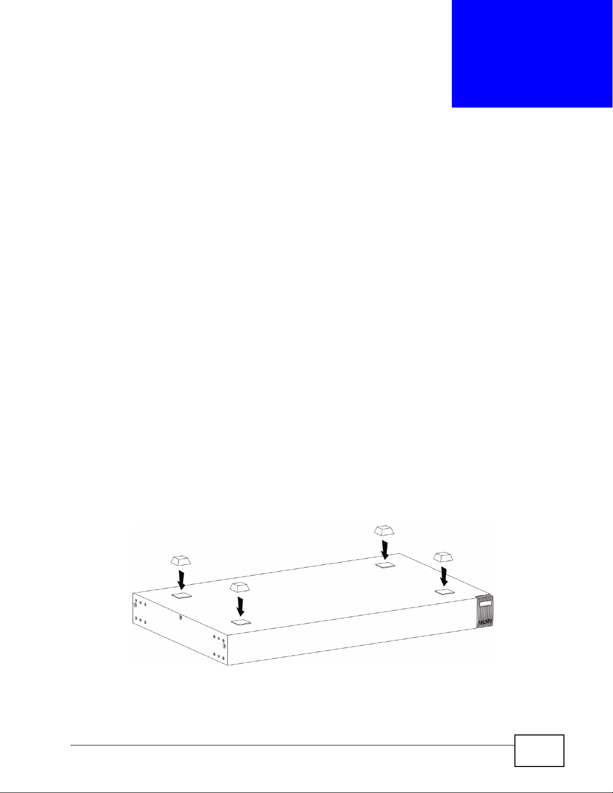
4 Remove the adhesive backing from the rubber feet.
5 Attach the rubber feet to each corner on the bottom of the Switch. These rubber
feet help protect the Switch from shock or vibration and ensure space between
devices when stacking.
Figure 5 Attaching Rubber Feet
GS1510 Series User’s Guide
23
Page 24

Chapter 2 Hardware Installation and Connection
Note: Do NOT block the ventilation holes. Leave space between devices when
stacking.
For proper ventilation, allow at least 4 inches (10 cm) of clearance at the front
and 3.4 inches (8 cm) at the back of the Switch. This is especially important for
enclosed rack installations.
2.2 Mounting the Switch on a Rack
This section lists the rack mounting requirements and precautions and describes
the installation steps.
2.2.1 Rack-mounted Installation Requirements
• Two mounting brackets.
• Eight M3 flat head screws and a #2 Philips screwdriver.
• Four M5 flat head screws and a #2 Philips screwdriver.
Note: Failure to use the proper screws may damage the unit.
2.2.1.1 Precautions
• Make sure the rack will safely support the combined weight of all the equipment
it contains.
• Make sure the position of the Switch does not make the rack unstable or topheavy. Take all necessary precautions to anchor the rack securely before
installing the unit.
2.2.2 Attaching the Mounting Brackets to the Switch
1 Position a mounting bracket on one side of the Switch, lining up the four screw
holes on the bracket with the screw holes on the side of the Switch.
Figure 6 Attaching the Mounting Brackets
24
GS1510 Series User’s Guide
Page 25
Chapter 2 Hardware Installation and Connection
2 Using a #2 Philips screwdriver, install the M3 flat head screws through the
mounting bracket holes into the Switch.
3 Repeat steps 1 and 2 to install the second mounting bracket on the other side of
the Switch.
4 You may now mount the Switch on a rack. Proceed to the next section.
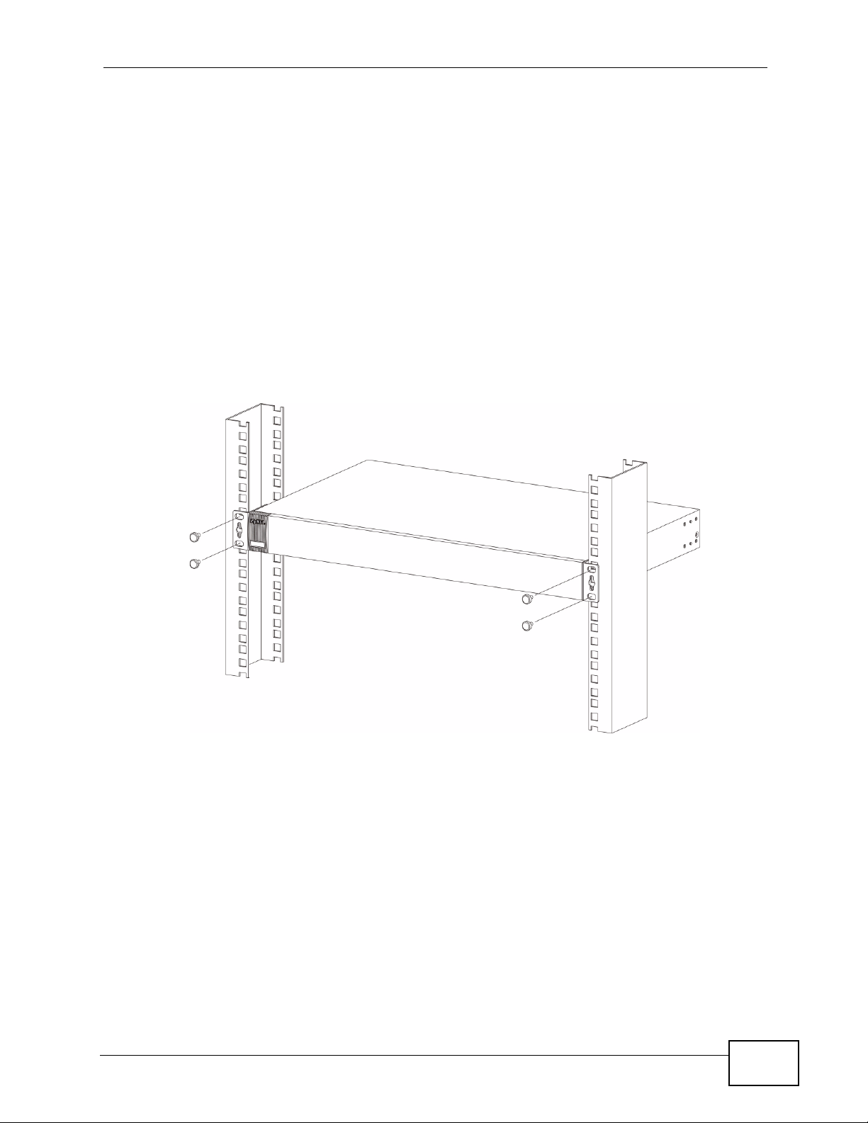
2.2.3 Mounting the Switch on a Rack
1 Position a mounting bracket (that is already attached to the Switch) on one side of
the rack, lining up the two screw holes on the bracket with the screw holes on the
side of the rack.
Figure 7 Mounting the Switch on a Rack
2 Using a #2 Philips screwdriver, install the M5 flat head screws through the
mounting bracket holes into the rack.
3 Repeat steps 1 and 2 to attach the second mounting bracket on the other side of
the rack.
GS1510 Series User’s Guide
25
Page 26

Chapter 2 Hardware Installation and Connection
26
GS1510 Series User’s Guide
Page 27

CHAPTER 3
Hardware Overview
This chapter describes the front panel and rear panel of the Switch and shows you
how to make the hardware connections.
3.1 Front Panel
The figures below show the front panel of the Switch.
Figure 8 GS1510-16 Front Panel
LEDs
Figure 9 GS1510-24 Front Panel
LEDs
RJ-45 Gigabit Ethernet
RJ-45 Gigabit Ethernet
Mini-GBIC
GS1510 Series User’s Guide
27
Page 28

Chapter 3 Hardware Overview
The following table describes the ports on the panels.
Table 1 Panel Connections
CONNECTO
R
RJ-45 Gigabit
Ethernet
Ports
Mini-GBIC
Slots
(GS1510-24
only)
DESCRIPTION
Connect these Gigabit Ethernet ports to high-bandwidth backbone network
Ethernet switches or use them to daisy-chain other switches.
Use mini-GBIC transceivers in these slots for fiber-optic connections to
backbone Ethernet switches.
3.1.1 Ethernet Ports
The GS1510-16 has 16 auto-negotiating, auto-crossover RJ-45 Gigabit Ethernet
ports.
The GS1510-24 has 24 auto-negotiating, auto-crossover RJ-45 Gigabit Ethernet
ports.
The speed of the Gigabit Ethernet ports can be 10 Mbps, 100Mbps or 1000Mbps
and the duplex mode can be half duplex (at 100 Mbps) or full duplex.
An auto-negotiating port can detect and adjust to the optimum Ethernet speed
(100/1000Mpbs) and duplex mode (full duplex or half duplex) of the connected
device.7
An auto-crossover (auto-MDI/MDI-X) port automatically works with a straightthrough or crossover Ethernet cable.
3.1.1.1 Default Ethernet Settings
The factory default negotiation settings for the Ethernet ports on the Switch are:
• Speed: Auto
•Duplex: Auto
• Flow control: Off
3.1.2 Mini-GBIC Slots
There are two mini-GBIC (Gigabit Interface Converter) slots for mini-GBIC
transceivers on GS1510-24. A transceiver is a single unit that houses a
transmitter and a receiver. The Switch does not come with transceivers. You must
use transceivers that comply with the SFP Transceiver MultiSource Agreement
(MSA). See the SFF committee’s INF-8074i specification Rev 1.0 for details.
28
GS1510 Series User’s Guide
Page 29

You can change transceivers while the Switch is operating. You can use different
transceivers to connect to Ethernet switches with different types of fiber-optic
connectors.
• Type: SFP connection interface
• Connection speed: 1 Gigabit per second (Gbps)
Note: To avoid possible eye injury, do not look into an operating fiber-optic module’s
connectors.
3.1.2.1 Transceiver Installation
Use the following steps to install a mini GBIC transceiver (SFP module).
1 Insert the transceiver into the slot with the exposed section of PCB board facing
down.
Figure 10 Transceiver Installation Example
Chapter 3 Hardware Overview
2 Press the transceiver firmly until it clicks into place.
3 The Switch automatically detects the installed transceiver. Check the LEDs to
verify that it is functioning properly.
Figure 11 Installed Transceiver
3.1.2.2 Transceiver Removal
Use the following steps to remove a mini GBIC transceiver (SFP module).
GS1510 Series User’s Guide
29
Page 30

Chapter 3 Hardware Overview
1 Open the transceiver’s latch (latch styles vary).
Figure 12 Opening the Transceiver’s Latch Example
2 Pull the transceiver out of the slot.
Figure 13 Transceiver Removal Example
3.1.3 The RESET Button
Reset the Switch to its factory default configuration via the RESET button. Press
the RESET button for at least five seconds and then release. The Switch
automatically reboots and reloads its factory default configuration file. The RESET
button is on the front panel of the Switch.
Note: When you use the RESET button all of your configuration settings will be lost.
Use the default IP address (192.168.1.1) and user name (admin) and password
(1234) to log back into the Switch. It may take up to 2 minutes for the Switch to
restart when you reload the default configuration file.
3.2 LEDs
The following table describes the LEDs.
Table 2 LEDs
LED STATUS DESCRIPTION
PWR Green On The system is turned on.
Off The system is off.
SYS Green On The system is on and functioning properly.
Off The system is off or is malfunctioning.
30
GS1510 Series User’s Guide
Page 31

Chapter 3 Hardware Overview
Table 2 LEDs (continued)
LED STATUS DESCRIPTION
Gigabit Ethernet Ports
LINK/ACT Green On The link to a 10/1000 Mbps Ethernet network is up.
Amber On The link to a 100 Mbps Ethernet network is up.
Blinking The port is transmitting/receiving data.
Off The link to an Ethernet network is down.
FDX Amber On The port is negotiating in full-duplex mode.
Off The port is negotiating in half-duplex mode and no
collisions are occurring.
Mini-GBIC Slots (GS1510-24 ONLY)
LNK/ACT Green On The port has a successful connection.
Blinking The port is receiving or transmitting data.
Off No Ethernet device is connected to this port or the link to
an Ethernet network is down.
3.3 Rear Panel
The following figures show the rear panels of the AC power input model Switch.
The rear panel contains a receptacle for the power cord.
Figure 14 GS1510-16 Rear Panel
Figure 15 GS1510-24 Rear Panel
3.3.1 Power Connector
Make sure you are using the correct power source as shown on the panel.
GS1510 Series User’s Guide
31
Page 32

Chapter 3 Hardware Overview
To connect the power to the Switch, insert the female end of the power cord into
the power receptacle on the rear panel. Connect the other end of the supplied
power cord to a 100~240V AC, 50/60 Hz power outlet capable of supplying at
least 0.3A.
32
GS1510 Series User’s Guide
Page 33

PART II
Basic Settings
The Web Configurator (35)
System (45)
General Settings (47)
MAC Management (51)
Port Mirroring (55)
Port Settings (57)
33
Page 34

34
Page 35

CHAPTER 4
The Web Configurator
This section introduces the configuration and functions of the Web Configurator.
4.1 Introduction
The Web Configurator is an HTML-based management interface that allows easy
setup and management of the Switch via an Internet browser. Use Internet
Explorer 6.0 or later to access the web configurator. The recommended screen
resolution is 1024 by 768 pixels.
In order to use the Web Configurator you need to allow:
• Web browser pop-up windows from your device. Web pop-up blocking is enabled
by default in Windows XP SP (Service Pack) 2.
• JavaScript (enabled by default).
• Java permissions (enabled by default).
Note: This User’s Guide shows screens from the GS1510 Series, unless otherwise
specified.
4.2 Device Auto Discovery Utility
To access the web configurator, you will need to know the IP address of the
Switch. If the default IP address (192.168.1.1) has been changed, use the ZyXEL
device discovery utility to easily locate the Switch on your network. The utility can
be found on the CD that came with the Switch, see Appendix A on page 159 for
installation and usage details.
4.3 System Login
1 Start your web browser.
GS1510 Series User’s Guide
35
Page 36

Chapter 4 The Web Configurator
2 Type “http://” and the IP address of the Switch (for example, the default is
192.168.1.1) in the Location or Address field. Press [ENTER].
3 The login screen appears. The default username is admin and the associated
default password is 1234.
Figure 16 Web Configurator: Login
4 Click Login to view the first Web Configurator screen.
4.3.1 Smart Mode
The Smart mode screens enable you to quickly set up important options such as
basic IP settings, Energy Efficient Ethernet, Web Authentication, DHCP Snooping
and Spanning Tree Protocol (STP).
To go directly to the Advance mode settings, see Section 4.3.2 on page 40.
36
GS1510 Series User’s Guide
Page 37

4.3.1.1 IP Setting
The Smart > IP Setting screen is the first screen that displays when you access
the Web Configurator. Use this screen to configure the IP address and subnet
mask for the Switch. Click Apply to save the changes.
Figure 17 Web Configurator Smart Screen - IP Setting
Chapter 4 The Web Configurator
4.3.1.2 EEE (Energy Efficient Ethernet)
Use this screen to reduce energy consumption over RJ-45 Ethernet Ports during
idle periods. Click the EEE tab (Energy Efficient Ethernet) to display the screen as
shown next.
You can enable IEEE 802.3az Energy Efficient Ethernet on a port by clicking on it
in the Switch graphic.
Click Apply to save any changes.
Figure 18 Web Configurator Smart Screen - EEE
GS1510 Series User’s Guide
37
Page 38

Chapter 4 The Web Configurator
4.3.1.3 Web Authentication
Click the Web Authentication tab to open the screen as shown next. This feature
is used to authenticate users before they access a website on the Internet. Use
the ON or OFF button on this screen to globally enable/disable web authentication
across all ports.
You can enable or disable web authentication on a specific port by clicking on it.
When a port is green, it means authentication is enabled on the port. The default
user name and password for web authentication is guest/guest. You can change
the password on this screen.
The Management > User Account screen (Section 23.2 on page 143) allows
you to create more user accounts for web authentication.
Click Apply to save any changes.
Figure 19 Web Authentication Smart Screen - Web Authentication
4.3.1.4 DHCP Snooping
Use this screen to enable or disable the DHCP Snooping feature which filters
unauthorized DHCP packets on the network.
Click the DHCP Snooping tab to open the screen as shown next. Use the ON or
OFF button on this screen to enable or disable DHCP Snooping. You can set a
specific port to act as a server port by clicking on it to make it green. A server port
is a port that is connected to a DHCP server.
Note: You can only enable one port as a server port on this screen, to enable more
than one port, use the advanced DHCP snooping screen (Section 18.4 on
page 107).
38
GS1510 Series User’s Guide
Page 39

Click Apply to save any changes.
Figure 20 Web Configuration Smart Screen - DHCP Snooping
4.3.1.5 STP (Spanning Tree Protocol)
Chapter 4 The Web Configurator
Use this screen to activate the Spanning Tree Protocol (STP) feature which is used
to prevent loops in the core of your network.
Click the STP tab to open the screen as shown next. Use the OFF or ON button to
globally enable or disable Spanning Tree Protocol for the Switch.
Figure 21 Web Configurator Smart Screen - STP
GS1510 Series User’s Guide
39
Page 40

Chapter 4 The Web Configurator
4.3.2 The Advanced Main Screen
Click Advance to display the following screen that shows the main navigating
components of the Web Configurator screen.
Figure 22 Web Configurator Advanced Screens (System Information)
C
A
B
D
A - The device graphic displays the status of the ports.
B - Use the About link to view more information about the device’s vendor. Use
the Logout link to exit the Web Configurator. Use the Smart button to go to the
smart screens where you can quickly set up some main functions. Use the
Advanced button to go to the advanced configuration screens.
C - The navigation panel has links to screens that let you configure the Switch’s
features.
D - The function frame allows you to view and edit individual feature settings.
4.3.3 The Navigation Panel
Navigate to individual feature configuration screens from the navigation panel.
40
GS1510 Series User’s Guide
Page 41

Chapter 4 The Web Configurator
The following table describes the links in the navigation panel.
Table 3 Navigation Panel Links
LINK DESCRIPTION
System Status
System
Information
Basic Settings
General Settings Use these screens to configure the system name, IP address,
MAC
Management
Port Mirroring Use this screen to copy traffic from one port or ports to another port in
Port Settings Use this screen to enable/disable a port, configure the port speed and
Advanced Settings
VLAN
Port Isolation Use this screen to isolate each port from communicating with each
VLAN Use these screens to create new IEEE 802.1Q VLANs as well as
EEE Use this screen to enable/disable Energy Efficient Ethernet on each
IGMP Snooping Use this screen to configure multicast related settings such as IGMP
Link
Aggregation
Loop Guard Use this screen to configure protection against network loops that
QoS Use these screens to configure 802.1p priority, IP Diffserv (DSCP),
Storm Control Use this screen to cap the rate of broadcast, multicast and destination
STP Use these screens to configure the STP/RSTP to prevent network loops.
Security
IP Source Guard
DHCP
Snooping
ARP
Inspection
Binding Table Use this screen to view the information of any hosts which successfully
Use these screens to view general system information such as firmware
version, IP address and so on.
maximum frame size, and system time settings.
Use these screens to configure static MAC address settings and view
the MAC table.
order that you can examine the traffic from the first port without
interference.
duplex and flow control, and view the current connection status.
other. Each port can only communicate with the CPU management port.
configuring Port VLAN ID (PVID), tag/untag, and acceptable frame
settings.
port.
Snooping, IGMP Snooping VLAN, unknown multicast packet handling,
and immediate leave ports.
Uses these screens to logically aggregate physical links to form one
logical, higher-bandwidth link.
occur on the edge of your network.
queuing method with associated queue weights and priority/queue
mapping for the Switch.
lookup failure (DLF) packets the Switch will allow on individual ports.
Use these screens to configure filtering of unauthorized DHCP packets
in your network.
Use these screens to configure filtering of unauthorized ARP packets in
your network.
connected to an IP address through the DHCP server.
GS1510 Series User’s Guide
41
Page 42

Chapter 4 The Web Configurator
Table 3 Navigation Panel Links (continued)
LINK DESCRIPTION
802.1x Use this screen to configure 802.1x authentication method. This
Web
Authentication
Management
Maintenance Use this screen to perform firmware upgrades, configuration backup
SNMP Use this screen to reboot the Switch or to restore the default
User Account Use this screen to create users and assign them to pre-defined SNMP
method uses an authentication server (RADIUS server) to validate
access to a port based on a username and password provided by the
user.
Use this screen to configure settings that define when notifications are
sent to an external management station.
and restore.
configuration of the Switch.
Use this screen to define security parameters for SNMP v1 and SNMP
v2c.
Use this screen to configure settings that define when notifications are
sent to an external management station.
groups.
4.3.4 Change Your Password
After you log in for the first time, it is recommended you change the default
administrator password. Click Management > User Account to display the next
screen. Click 1 in the No. field to change the admin password.
Figure 23 Change Administrator Login Password
42
GS1510 Series User’s Guide
Page 43

4.4 Saving Your Configuration
When you are done modifying the settings in a screen, click Apply to save your
changes back to the Switch.
4.5 Switch Lockout
You could block yourself (and all others) from using the Web Configurator if you:
1 Remove all the ports from the default VLAN (default is VLAN 1) when no other
VLANs exist.
2 Disable all ports.
3 Forget the password and/or IP address.
Chapter 4 The Web Configurator
4 Enable Dynamic ARP without entering the proper MAC to IP address binding.
4.6 Resetting the Switch
If you lock yourself (and others) from the Switch or forget the administrator
password, you will need to reset the Switch back to the factory defaults.
Use the RESET button to reset the Switch back to factory defaults. Press and hold
the RESET button for five seconds. The Switch will reload its factory defaults.
The Switch is now reinitialized with a default configuration file including the default
administrator username (admin) and password (1234). The IP address of the
Switch also reverts to the default 192.168.1.1.
GS1510 Series User’s Guide
43
Page 44

Chapter 4 The Web Configurator
4.7 Logging Out of the Web Configurator
Click Logout on the top right corner of the screen to exit the Web Configurator.
You have to log in with your password again after you log out. This is
recommended after you finish a management session for security reasons.
Figure 24 Web Configurator: Logout Link
44
GS1510 Series User’s Guide
Page 45

CHAPTER 5
System
This chapter describes the system screens.
5.1 System Screen
The home screen of the Web Configurator displays general system information.
Click System Status > System Information in the navigation panel to view
device specific information such as host name, firmware version and so on.
Figure 25 System
The following table describes the labels in this screen.
Table 4 System
LABEL DESCRIPTION
Model Name This field displays the model name of your Switch.
Host Name This field displays the name of your Switch.
Boot Code
Version
GS1510 Series User’s Guide
This field displays the boot code version.
45
Page 46

Chapter 5 System
Table 4 System (continued)
LABEL DESCRIPTION
Firmware
Version
Built Date This field displays the date of the currently installed firmware.
DHCP Client This field displays whether the DHCP client feature is enabled or disabled.
IP Address This field indicates the IP address of the Switch.
Subnet Mask This field indicates the subnet mask of the Switch.
Default
Gateway
MAC Address This field displays the MAC (Media Access Control) address of the Switch.
Management
VLAN
CPU Loading This field displays the percentage of your Switch’s system load.
Memory
Information
Current Time This field displays current date (yyyy-mm-dd) and time (hh:mm:ss).
Refresh Click this to update the information in this screen.
This field displays the version number of the Switch's current firmware.
Click Upgrade to go to the firmware upgrade screen. See Section 21.3.2
on page 131.
You can click the existing IP address to change it. See Section 6.2 on
page 47.
This field indicates the IP address of the default gateway.
This field displays the VLAN ID that is used for the Switch management
purposes.
This field displays the total memory the Switch has and the memory
which is currently available (Free) and occupied (Usage).
46
GS1510 Series User’s Guide
Page 47

CHAPTER 6
General Settings
This chapter describes the General Settings screens in the Basic Settings menu.
6.1 What You Can Do
•Use the System screen (Section 6.2 on page 47) to configure the basic IP
address settings for the Switch.
•Use the Jumbo Frame screen (Section 6.3 on page 48) to configure the jumbo
frame size the Switch accepts.
•Use the SNTP screen (Section 6.4 on page 49) to configure the date and time of
the Switch.
6.2 System
Use the System Settings screen under Basic Settings > General Settings to set up
the IP address for the Switch. You can enable DHCP or set up a static IP address.
The following screen appears when you click Basic Settings > General Settings
> System.
Figure 26 System Settings
GS1510 Series User’s Guide
47
Page 48

Chapter 6 General Settings
The following table describes the labels in this screen.
Table 5 System Settings
LABEL DESCRIPTION
Hostname Enter up to 16 alphanumeric characters for the name of
DHCP Client Select Enable to allow the Switch to automatically get
Static IP Address Enter the IP address of your Switch in dotted decimal
Subnet Mask Enter the IP subnet mask of your Switch in dotted
Default Gateway Enter the IP address of the default outgoing gateway in
Management VLAN Enter a VLAN ID used for Switch management purposes.
Apply Click Apply to save your changes back to the Switch.
Refresh Click Refresh to begin configuring this screen afresh.
your Switch. Hyphens (-) and underscores (_) are also
allowed.
an IP address from a DHCP server. Click Renew to have
the Switch reget an IP address from the DHCP server.
Select Disable if you want to configure the Switch’s IP
address manually.
notation. For example, 192.168.1.1.
decimal notation for example 255.255.255.0.
dotted decimal notation, for example 192.168.1.5.
6.3 Jumbo Frame
Jumbo frames are Ethernet frames with a payload greater than 1500 bytes. Jumbo
frames can enhance data transmission efficiency in a Gigabit network.
Use this screen to configure the jumbo frame size the Switch accepts. Click Basic
Settings > General Settings > Jumbo Frame to display the screen as shown.
Figure 27 Basic Settings > General Settings > Jumbo Frame
The following table describes the labels in this screen.
Table 6 Basic Settings > General Settings > Jumbo Frame
LABEL DESCRIPTION
Frame Size Select the maximum number of bytes (1522, 1536, 1552 or 9216) of a
jumbo frame. The bigger the frame size, the better the performance.
48
GS1510 Series User’s Guide
Page 49

Table 6 Basic Settings > General Settings > Jumbo Frame (continued)
LABEL DESCRIPTION
Apply Click Apply to save your changes back to the Switch.
Refresh Click Refresh to begin configuring this screen afresh.
6.4 SNTP
Use this screen to configure system date and time. Click Basic Settings >
General Settings > SNTP to display the screen as shown.
Figure 28 Basic Settings > General Settings > SNTP
Chapter 6 General Settings
The following table describes the labels in this screen.
Table 7 Basic Settings > General Settings > SNTP
LABEL DESCRIPTION
Current Time and Date
Current Time This field displays the time you open this menu (or refresh the menu).
Current Date This field displays the date you open this menu.
Time and Date Settings
Manual Select this option if you want to enter the system date and time
New Time Enter the new date in year, month and day format and time in hour,
GS1510 Series User’s Guide
manually.
minute and second format. The new date and time then appear in the
Current Date and Current Time fields after you click Apply.
49
Page 50

Chapter 6 General Settings
Table 7 Basic Settings > General Settings > SNTP (continued)
LABEL DESCRIPTION
Enable
Network Time
Protocol
NTP Server Select a pre-designated time server or type the IP address of your time
Time Zone Select the time difference between UTC (Universal Time Coordinated,
Daylight Saving Settings
Daylight saving is a period from late spring to early fall when many countries set their
clocks ahead of normal local time by one hour to give more daytime light in the evening.
State Select Enable if you want to use Daylight Saving Time. Otherwise,
Start Date Configure the day and time when Daylight Saving Time starts if you
Select this option to use Network Time Protocol (NTP) for the time
service.
server. The Switch searches for the timeserver for up to 60 seconds.
formerly known as GMT, Greenwich Mean Time) and your time zone from
the drop-down list box.
select Disable to turn it off.
enabled Daylight Saving Time. The time is displayed in the 24 hour
format. Here are a couple of examples:
Daylight Saving Time starts in most parts of the United States on the
second Sunday of March. Each time zone in the United States starts
using Daylight Saving Time at 2 A.M. local time. So in the United States
you would select Second, Sunday, March and 2:00.
Daylight Saving Time starts in the European Union on the last Sunday of
March. All of the time zones in the European Union start using Daylight
Saving Time at the same moment (1 A.M. GMT or UTC). So in the
European Union you would select Last, Sunday, March and the last
field depends on your time zone. In Germany for instance, you would
select 2:00 because Germany's time zone is one hour ahead of GMT or
UTC (GMT+1).
End Date Configure the day and time when Daylight Saving Time ends if you
enabled Daylight Saving Time. The time field uses the 24 hour format.
Here are a couple of examples:
Daylight Saving Time ends in the United States on the last Sunday of
October. Each time zone in the United States stops using Daylight Saving
Time at 2 A.M. local time. So in the United States you would select First,
Sunday, November and 2:00.
Daylight Saving Time ends in the European Union on the last Sunday of
October. All of the time zones in the European Union stop using Daylight
Saving Time at the same moment (1 A.M. GMT or UTC). So in the
European Union you would select Last, Sunday, October and the last
field depends on your time zone. In Germany for instance, you would
select 2:00 because Germany's time zone is one hour ahead of GMT or
UTC (GMT+1).
Apply Click Apply to save your changes back to the Switch.
Refresh Click Refresh to begin configuring this screen afresh.
50
GS1510 Series User’s Guide
Page 51

CHAPTER 7
MAC Management
7.1 Overview
Use these screens to add, delete and view entries in the MAC address table.
The MAC Table (a MAC table is also known as a filtering database) shows how
frames are forwarded or filtered across the Switch’s ports. When a device (which
may belong to a VLAN group) sends a packet which is forwarded to a port on the
Switch, the MAC address of the device is shown on the Switch’s MAC Table. It also
shows whether the MAC address is dynamic (learned by the Switch) or static
(manually entered).
7.2 What You Can Do
•Use the Static MAC Settings screen (Section 7.4 on page 52) to manually add
a static MAC address to the table.
•Use the MAC Table screen (Section 7.5 on page 53) to view the static and
dynamic MAC address entries.
7.3 What You Need to Know
The Switch uses the MAC Table to determine how to forward frames. See the
following figure.
1 The Switch examines a received frame and learns the port from which this source
MAC address came.
2 The Switch checks to see if the frame's destination MAC address matches a source
MAC address already learned in the MAC Table.
• If the Switch has already learned the port for this MAC address, then it forwards
the frame to that port.
GS1510 Series User’s Guide
51
Page 52

Chapter 7 MAC Management
• If the Switch has not already learned the port for this MAC address, then the
frame is flooded to all ports. Too much port flooding leads to network
congestion.
• If the Switch has already learned the port for this MAC address, but the
destination port is the same as the port it came in on, then it filters the frame.
Figure 29 MAC Table Flowchart
7.4 Static MAC Settings
A static Media Access Control (MAC) address is an address that has been manually
entered in the MAC address table. Static MAC addresses do not age out. When you
set up static MAC address rules, you are setting static MAC addresses for a port.
This may reduce the need for broadcasting.
Click Basic Settings > MAC Management > Static MAC Settings in the
navigation panel to display the configuration screen as shown.
Figure 30 Static MAC Settings
52
GS1510 Series User’s Guide
Page 53

Chapter 7 MAC Management
The following table describes the labels in this screen.
Table 8 Static MAC Settings
LABEL DESCRIPTION
Static MAC Settings
MAC Address Enter the MAC address of a computer or device that you want to add to the
MAC address table.
VLAN ID Enter the VLAN ID to apply to the computer or device.
Port Enter the port number to which the computer or device is connected.
Apply Click Apply to add the MAC address entry to the MAC address table.
Refresh Click Refresh to begin configuring this screen afresh.
Static MAC Table
MAC Address This field displays the MAC address of a manually entered MAC address
entry.
VLAN ID This field displays the VID of a manually entered MAC address entry.
Port This field displays the port number of a manually entered MAC address
entry. The MAC address with the port listed as CPU is the Switch’s MAC
address.
Action Click Delete to remove this manually entered MAC address entry from the
MAC address table. You cannot delete the Switch’s MAC address from the
static MAC address table.
7.5 MAC Table
Use the MAC Table screen to view entries in the MAC address table. Click Basic
Settings > MAC Management > MAC Table in the navigation panel to display
the screen as shown.
Figure 31 MAC Table
GS1510 Series User’s Guide
53
Page 54

Chapter 7 MAC Management
The following table describes the labels in this screen.
Table 9 MAC Table
LABEL DESCRIPTION
Show Type
Apply
Refresh Click this to update the information in the MAC table.
MAC Address This field displays a MAC address.
Type This field displays whether this entry was entered manually (Static) or
VLAN ID This field displays the VLAN ID of the MAC address entry.
Port This field displays the port number the MAC address entry is associated. It
Select Static, Dynamic, or All and then click Apply to display the
corresponding MAC address entries on this screen.
whether it was learned by the Switch (Dynamic).
displays CPU if it is the entry for the Switch itself.
54
GS1510 Series User’s Guide
Page 55

CHAPTER 8
Port Mirroring
This chapter discusses port mirroring.
8.1 Port Mirroring Settings
Port mirroring allows you to copy traffic flow to a monitor port (the port you copy
the traffic to) in order that you can examine the traffic from the mirrored port
without interference.
Click Basic Settings > Port Mirroring to display the following screen. Use this
screen to select a monitor port and specify the traffic flow to be copied to the
monitor port.
Figure 32 Port Mirroring
GS1510 Series User’s Guide
55
Page 56

Chapter 8 Port Mirroring
The following table describes the labels in this screen.
Table 10 Port Mirroring
LABEL DESCRIPTION
State Select Enabled to turn on port mirroring or select Disabled to turn it off.
Monitor
to Port
All Ports Settings in this field apply to all ports.
Source
Port
Mirror
Mode
Apply Click Apply to save your changes back to the Switch.
Refresh Click Refresh to begin configuring this screen afresh.
Select the ports for which you want to monitor the traffic.
Use this field only if you want to make some settings the same for all ports.
Use this field first to set the common settings and then make adjustments on
a port-by-port basis.
This field displays the number of a port.
Select Ingress, Egress or Both to only copy the ingress (incoming), egress
(outgoing) or both (incoming and outgoing) traffic from the source ports to
the port specified in the Monitor to Port field. Select Disable to not copy
any traffic from the source ports to the port specified in the Monitor to Port
field.
56
GS1510 Series User’s Guide
Page 57

CHAPTER 9
Port Settings
This chapter describes how to view and configure the port settings on the Switch.
9.1 Port Settings
Use this screen to configure and view Switch port settings. Click Basic Settings >
Port Settings to display the following screen.
9.1.1 Auto Negotiation
Auto (auto-negotiation) allows one port to negotiate with a peer port
automatically to obtain the connection speed and duplex mode that both ends
support. When auto-negotiation is turned on, a port on the Switch negotiates with
the peer automatically to determine the connection speed and duplex mode.
If the peer port does not support auto-negotiation or turns off this feature, the
Switch determines the connection speed by detecting the signal on the cable and
using half duplex mode. When the Switch’s auto-negotiation is turned off, a port
uses the pre-configured speed and duplex mode when making a connection, thus
requiring you to make sure that the settings of the peer port are the same in order
to connect.
9.1.2 Flow Control
A concentration of traffic on a port decreases port bandwidth and overflows buffer
memory causing packet discards and frame losses. Flow Control is used to
regulate transmission of signals to match the bandwidth of the receiving port.
The Switch uses IEEE802.3x flow control in full duplex mode and backpressure
flow control in half duplex mode.
IEEE802.3x flow control is used in full duplex mode to send a pause signal to the
sending port, causing it to temporarily stop sending signals when the receiving
port memory buffers fill.
GS1510 Series User’s Guide
57
Page 58

Chapter 9 Port Settings
Back Pressure flow control is typically used in half duplex mode to send a
"collision" signal to the sending port (mimicking a state of packet collision)
causing the sending port to temporarily stop sending signals and resend later.
Figure 33 Port Settings
58
GS1510 Series User’s Guide
Page 59

Chapter 9 Port Settings
The following table describes the labels in this screen.
Table 11 Port Settings
LABEL DESCRIPTION
Port Settings
Port Select a port number you want to configure on this screen.
State Select Enable to activate the port or Disable to deactivate the port.
Speed/Duplex Select the speed and duplex mode of the port. The choices are:
• Auto
• 10 Mbps / Full Duplex
• 10 Mbps / Half Duplex
• 100 Mbps / Full Duplex
• 100 Mbps / Half Duplex
• 1000 Mbps / Full Duplex
• 1000 Mbps / Half Duplex
Flow Control Select On to enable access to buffering resources for the port thus
ensuring lossless operation across network switches. Otherwise, select
Off to disable it.
Apply Click Apply to save the changes back to the Switch.
Refresh Click Refresh to begin configuring this screen afresh.
Port Status
Port This field displays the port number.
State This field displays whether the port is enabled or disabled.
Speed/Duplex This field displays the speed either 10M, 100M or 1000M and the duplex
mode Full or Half.
Flow Control
Link Status This field displays the link status of the port. If the port is up, it displays
This field displays whether the port’s flow control is On or
the port’s speed, duplex and flow control setting. Otherwise, it displays
Link Down if the port is disabled or not connected to any device.
Off.
GS1510 Series User’s Guide
59
Page 60

Chapter 9 Port Settings
60
GS1510 Series User’s Guide
Page 61

PART III
Advanced Settings
VLAN (63)
EEE (71)
IGMP Snooping (73)
Link Aggregation (77)
Loop Guard (81)
QoS (85)
Storm Control (93)
Spanning Tree Protocol (95)
61
Page 62

62
Page 63

CHAPTER 10
VLAN
10.1 Overview
This chapter shows you how to configure IEEE 802.1Q tagged VLANs and portbased VLANs.
10.2 What You Can Do
•Use the Port Isolation screen (Section 10.4 on page 64) to specify which ports
can communicate with each other.
•Use the VLAN Settings screen (Section 10.5 on page 67) to configure a VLAN
and assign member ports.
•Use the Tag Settings screen (Section 10.6 on page 68) to add a VLAN ID tag to
all outgoing frames on a member port.
•Use the Port Settings screen (Section 10.7 on page 69) to configure the VLAN
port settings.
10.3 What You Need to Know
10.3.1 Introduction to IEEE 802.1Q Tagged VLANs
A tagged VLAN uses an explicit tag (VLAN ID) in the MAC header to identify the
VLAN membership of a frame across bridges - they are not confined to the switch
on which they were created. The VLANs can be created statically by hand or
dynamically through GVRP. The VLAN ID associates a frame with a specific VLAN
and provides the information that switches need to process the frame across the
network. A tagged frame is four bytes longer than an untagged frame and
contains two bytes of TPID (Tag Protocol Identifier, residing within the type/length
field of the Ethernet frame) and two bytes of TCI (Tag Control Information, starts
after the source address field of the Ethernet frame).
GS1510 Series User’s Guide
63
Page 64

Chapter 10 VLAN
The CFI (Canonical Format Indicator) is a single-bit flag, always set to zero for
Ethernet switches. If a frame received at an Ethernet port has a CFI set to 1, then
that frame should not be forwarded as it is to an untagged port. The remaining
twelve bits define the VLAN ID, giving a possible maximum number of 4,096
VLANs. Note that user priority and VLAN ID are independent of each other. A
frame with VID (VLAN Identifier) of null (0) is called a priority frame, meaning that
only the priority level is significant and the default VID of the ingress port is given
as the VID of the frame. Of the 4096 possible VIDs, a VID of 0 is used to identify
priority frames and value 4095 (FFF) is reserved, so the maximum possible VLAN
configurations are 4,094.
TPID
2 Bytes
User Priority
3 Bits
CFI
1 Bit
VLAN ID
12 bits
10.3.2 Forwarding Tagged and Untagged Frames
Each port on the Switch is capable of passing tagged or untagged frames. To
forward a frame from an 802.1Q VLAN-aware switch to an 802.1Q VLAN-unaware
switch, the Switch first decides where to forward the frame and then strips off the
VLAN tag. To forward a frame from an 802.1Q VLAN-unaware switch to an 802.1Q
VLAN-aware switch, the Switch first decides where to forward the frame, and then
inserts a VLAN tag reflecting the ingress port's default VID. The default PVID is
VLAN 1 for all ports, but this can be changed.
A broadcast frame (or a multicast frame for a multicast group that is known by the
system) is duplicated only on ports that are members of the VID (except the
ingress port itself), thus confining the broadcast to a specific domain.
10.4 Port Isolation
64
Use this screen to restrict specific ports on the Switch from communicating with
each other. This screen can also be used to specify which ports will forward
received packets to other ports on the Switch.
GS1510 Series User’s Guide
Page 65

Chapter 10 VLAN
Click Advanced Settings > VLAN > Port Isolation to display the following
screen.
Figure 34 Port Isolation
GS1510 Series User’s Guide
65
Page 66

Chapter 10 VLAN
The following table describes the labels in this screen.
Table 12 Port Isolation
LABEL DESCRIPTION
Port Select a port number to configure its port isolation settings.
Egress Port An egress port is an outgoing port, that is, a port through which a data
Select All/
Deselect All
Apply Click this to save any changes to the Switch.
Refresh Click this to reload the screen and reset any changes that were just made.
Port
Isolation
Status
Select All Ports to configure the port isolation settings for all ports on the
Switch.
packet leaves.
Selecting a port as an outgoing port means it will communicate with the
port currently being configured. If you wish to allow two subscriber ports to
talk to each other, you must define the egress port for both ports.
CPU refers to the Switch management port. By default it forms a VLAN
with all Ethernet ports. If it does not form a VLAN with a particular port
then the Switch cannot be managed from that port.
Click Select All to mark all ports as egress ports and permit traffic.
Click Deselect All to unmark all ports and isolate them.
Deselecting all ports means the port being configured cannot communicate
with any other port. This will also deselect the CPU outgoing port which will
disable Switch management for that port. This option is the most limiting
but also the most secure.
“V” indicates the port’s packets can be sent to that port.
“-” indicates the port’s packets cannot be sent to that port.
66
GS1510 Series User’s Guide
Page 67

10.5 VLAN Settings
Use this screen to configure a static VLAN and assign member ports to it. Click
Advanced Settings > VLAN > VLAN > VLAN Settings to display the following
screen.
Figure 35 VLAN Settings
Chapter 10 VLAN
The following table describes the labels in this screen.
Table 13 VLAN Settings
LABEL DESCRIPTION
VLAN ID Enter the VLAN ID for this entry; the valid range is between 1 and 4094.
VLAN Name Enter a descriptive name for the VLAN for identification purposes. This
name consists of up to 64 printable characters; spaces are allowed.
Member Port Enter the port numbers you want the Switch to assign to the VLAN as
members. You can designate multiple port numbers individually by using a
comma (,) and by range with a hyphen (-).
Apply Click this to save any changes to the Switch.
Refresh Click this to reload the screen and reset any changes that were just made.
VLAN List
VLAN ID This field displays the index number of the VLAN entry. Click the number to
modify the VLAN.
VLAN Name This field displays the name of the VLAN.
VLAN Status This field displays the status of the VLAN. Static or Dynamic (802.1Q
VLAN).
Member Port This field displays which ports have been assigned as members of the
VLAN. This will display None if no ports have been assigned.
Action Click Delete to remove the VLAN.
GS1510 Series User’s Guide
67
Page 68

Chapter 10 VLAN
10.6 Tag Settings
Use this screen to tag any outgoing frames from a port with its assigned VLAN ID.
You must first configure a VLAN (Section 10.5 on page 67) before using this
screen. Click Advanced Settings > VLAN > VLAN > Tag Settings to display
the following screen.
Figure 36 Tag Settings
The following table describes the labels in this screen.
Table 14 Tag Settings
LABEL DESCRIPTION
VLAN ID Select a VLAN ID to configure its port tagging settings.
Tag Port Selecting a port which is a member of the selected VLAN ID will make it a
tag port. This means the port will tag all outgoing frames transmitted with
the VLAN ID.
Select All Click Select All to mark all member ports as tag ports.
Deselect All Click Deselect All to mark all member ports as untag ports.
Apply Click this to save any changes to the Switch.
Refresh Click this to reload the screen and reset any changes that were just made.
Tag S t a t u s
VLAN ID This field displays the VLAN ID.
Tag Ports This field displays the ports that have been assigned as tag ports.
UnTag Ports This field displays the ports that have been assigned as untag ports.
68
GS1510 Series User’s Guide
Page 69

10.7 Port Settings
Use this screen to configure the VLAN port settings. Click Advanced Settings >
VLAN > VLAN > Port Settings to display the following screen.
Figure 37 Port Settings
Chapter 10 VLAN
The following table describes the labels in this screen.
Table 15 Port Settings
LABEL DESCRIPTION
Port Select a port number to configure from the drop-down box.
Select All to configure all ports at the same time.
PVID Select a PVID (Port VLAN ID number) from the drop-down box.
Acceptable
Frame
Apply Click this to save any changes to the Switch.
Refresh Click this to reload the screen and reset any changes that were just made.
Port Status
Specify the type of frames allowed on a port. Choices are All, VLAN
Untagged Only or VLAN Tagged Only.
Select All from the drop-down list box to accept all untagged or tagged
frames on this port. This is the default setting.
Select VLAN Untagged Only to accept only untagged frames on this port.
All tagged frames will be dropped.
Select VLAN Tagged Only to accept only tagged frames on this port. All
untagged frames will be dropped.
GS1510 Series User’s Guide
69
Page 70

Chapter 10 VLAN
Table 15 Port Settings (continued)
LABEL DESCRIPTION
Port This field displays the port number.
PVID This field displays the Port VLAN ID number.
Acceptable
Frame
This field displays the type of frames allowed on the port. This will either
display All or Tag Only.
70
GS1510 Series User’s Guide
Page 71

CHAPTER 11
EEE
11.1 Overview
This chapter explains the EEE (Energy Efficient Ethernet) screen.
Use this screen to reduce energy consumption over RJ-45 Ethernet Ports during
idle periods.
The hardware devices connected to the ports must also support EEE for this
function to work.
Note: A similar version of this screen appears in Smart Mode. See Section 4.3.1.2 on
page 37.
11.1.1 EEE Screen
Click Advanced Settings > EEE to view the screen as shown.
Figure 38 EEE
The following table describes the labels in this screen.
Table 16 EEE
LABEL DESCRIPTION
EEE Port State Click a port to enable IEEE 802.3az Energy Efficient Ethernet on
Select All Click this to enable IEEE 802.3az Energy Efficient Ethernet across
Deselect All Click this to disable IEEE 802.3az Energy Efficient Ethernet across
that port.
all ports.
all ports.
GS1510 Series User’s Guide
71
Page 72

Chapter 11 EEE
Table 16 EEE (continued)
LABEL DESCRIPTION
Apply Click this to save any changes to the Switch.
Refresh Click this to reload the screen and reset any changes that were just
made.
72
GS1510 Series User’s Guide
Page 73

CHAPTER 12
IGMP Snooping
12.1 Overview
This chapter shows you how to configure IGMP snooping for multicast traffic. The
Switch can passively snoop on IGMP packets transferred between IP multicast
routers/switches and IP multicast hosts to learn the IP multicast group
membership. IGMP snooping allows the Switch to learn multicast groups without
you having to manually configure them.
12.2 What You Can Do
•Use the General Settings screen (Section 12.4 on page 74) to enable IGMP
snooping.
•Use the Port Settings screen (Section 12.5 on page 75) to enable or disable
immediate leave on ports.
12.3 What You Need to Know
The Switch can passively snoop on IGMP packets transferred between IP multicast
routers/switches and IP multicast hosts to learn the IP multicast group
membership. It checks IGMP packets passing through it, picks out the group
registration information, and configures multicasting accordingly. IGMP snooping
allows the Switch to learn multicast groups without you having to manually
configure them.
The Switch forwards multicast traffic destined for multicast groups (that it has
learned from IGMP snooping or that you have manually configured) to ports that
are members of that group. IGMP snooping generates no additional network
traffic, allowing you to significantly reduce multicast traffic passing through your
Switch.
GS1510 Series User’s Guide
73
Page 74

Chapter 12 IGMP Snooping
12.3.1 IGMP Snooping and VLANs
The Switch can perform IGMP snooping on up to 4094 VLANs. You can configure
the Switch to automatically learn multicast group membership of any VLANs. The
Switch then performs IGMP snooping on the first VLANs that send IGMP packets.
This is referred to as auto mode. Alternatively, you can specify the VLANs that
IGMP snooping should be performed on. This is referred to as fixed mode. In fixed
mode the Switch does not learn multicast group membership of any VLANs other
than those explicitly added as an IGMP snooping VLAN.
12.4 General Settings
Click Advanced Settings > IGMP Snooping to display the screen as shown.
Figure 39 IGMP Snooping
74
The following table describes the labels in this screen.
Table 17 IGMP Snooping
LABEL DESCRIPTION
IGMP Snooping
State
IGMP Snooping
VLAN State
Unknown
Multicast
Packets
Apply Click Apply to save your changes to the Switch.
Refresh Click Refresh to begin configuring this screen afresh.
Select Enable to activate IGMP Snooping to forward group multicast
traffic only to ports that are members of that group. Select Disable to
disactivate the feature.
Select Add and enter VLANs upon which the Switch is to perform IGMP
snooping. The valid range of VLAN IDs is between 1 and 4094. Use a
comma (,) or hyphen (-) to specify more than one VLANs. Select
Delete and enter VLANs on which to have the Switch not perform IGMP
snooping.
Specify the action to perform when the Switch receives an unknown
multicast frame. Select Drop to discard the frame(s). Select Flooding
to send the frame(s) to all ports.
GS1510 Series User’s Guide
Page 75

Table 17 IGMP Snooping (continued)
LABEL DESCRIPTION
IGMP Snooping
State
IGMP Snooping
VLAN State
Unknown
Mulitcast
Packets
This field displays whether IGMP snooping is globally enabled or
disabled.
This field displays VLANs on which the Switch is to perform IGMP
snooping. None displays if you have not enabled IGMP snooping on any
port yet.
This field displays whether the Switch is set to discard or flood unknown
mulicast packets.
12.5 Port Settings
Click Advanced Applications > IGMP Snooping > Port Settings to open the
following screen. Use this screen to enable or disable immediate leave on ports.
When immediate leave is enabled on a port, the Switch removes a port from the
multicast table immediately when an IGMP leave report is received on that port.
Chapter 12 IGMP Snooping
Figure 40 IGMP Snooping Port Setting
The following table describes the labels in this screen.
Table 18 IGMP Snooping Port Setting
LABEL DESCRIPTION
Immediate
Leave Ports
Apply Click Apply to save your changes to the Switch.
Refresh Click Refresh to begin configuring this screen afresh.
Select individual ports on which to enable immediate leave.
Use Select All or Deselect All to enable or disable immediate leave for all
ports.
GS1510 Series User’s Guide
75
Page 76

Chapter 12 IGMP Snooping
76
GS1510 Series User’s Guide
Page 77

CHAPTER 13
Link Aggregation
13.1 Overview
This chapter shows you how to logically aggregate physical links to form one
logical, higher-bandwidth link.
13.2 What You Can Do
•Use the Static Trunk screen (Section 13.4 on page 78) to aggregate groups of
physical ports into one higher capacity link.
•Use the LACP screen (Section 13.5 on page 79) to enable Link Aggregation
Control Protocol (LACP).
13.3 What You Need to Know
Link Aggregation (Trunking) is the grouping of physical ports into one logical
higher-capacity link. You may want to trunk ports if for example, it is cheaper to
use multiple lower-speed links than to under-utilize a high-speed, but more costly,
single-port link.
However, the more ports you aggregate then the fewer available ports you have. A
trunk group is one logical link containing multiple ports.
The Switch supports both static and dynamic link aggregation.
Note: In a properly planned network, it is recommended to implement static link
aggregation only. This ensures increased network stability and control over the
trunk groups on your Switch.
13.3.1 Dynamic Link Aggregation
The Switch adheres to the IEEE 802.3ad standard for static and dynamic (LACP)
port trunking.
GS1510 Series User’s Guide
77
Page 78

Chapter 13 Link Aggregation
The IEEE 802.3ad standard describes the Link Aggregation Control Protocol
(LACP) for dynamically creating and managing trunk groups.
When you enable LACP link aggregation on a port, the port can automatically
negotiate with the ports at the remote end of a link to establish trunk groups.
LACP also allows port redundancy, that is, if an operational port fails, then one of
the “standby” ports become operational without user intervention. Please note
that:
• You must connect all ports point-to-point to the same Ethernet switch and
configure the ports for LACP trunking.
• LACP only works on full-duplex links.
• All ports in the same trunk group must have the same media type, speed,
duplex mode and flow control settings.
• Configure trunk groups or LACP before you connect the Ethernet switch to avoid
causing network topology loops.
13.4 Static Trunk
Use this screen to aggregate groups of physical ports into one higher capacity link.
Click Advanced Settings > Link Aggregation > Static Trunk to display the
following screen.
Figure 41 Static Trunk
78
GS1510 Series User’s Guide
Page 79

Chapter 13 Link Aggregation
The following table describes the labels in this screen.
Table 19 Static Trunk
LABEL DESCRIPTION
Group State Select the group ID to use for this trunk group, that is, one logical link
containing multiple ports.
Select Enable to use this static trunk group.
Member
Ports
Select All Click this to select all ports as members of the static trunk group.
Deselect All Click this to deselect all ports as members of the trunk gorup.
Apply Click Apply to save your changes to the Switch.
Refresh Click Refresh to begin configuring this screen afresh.
Group ID This field displays the group ID to identify a trunk group, that is, one logical
State This field displays if the trunk group is enabled or disabled.
Member
Ports
Select the ports to be added to the static trunk group.
link containing multiple ports.
This field displays the assigned ports that comprise the static trunk group.
13.5 LACP
Click Advanced Settings > Link Aggregation > LACP to display the following
screen. See Section 13.3.1 on page 77 for more information on dynamic link
aggregation.
Figure 42 LACP
GS1510 Series User’s Guide
79
Page 80

Chapter 13 Link Aggregation
The following table describes the labels in this screen.
Table 20 LACP
LABEL DESCRIPTION
State Select Enable from the drop down box to enable Link Aggregation Control
System
Priority
Group LACP Select a trunk group ID and then select whether to Enable or Disable
Apply Click Apply to save your changes to the Switch.
Refresh Click Refresh to begin configuring this screen afresh.
Group ID The field identifies the link aggregation group, that is, one logical link
LACP State This field displays if the group has LACP enabled.
Protocol (LACP).
Select Disable to not use LACP.
LACP system priority is a number between 1 and 65,535. The switch with
the lowest system priority (and lowest port number if system priority is the
same) becomes the LACP “server”. The LACP “server” controls the
operation of LACP setup. Enter a number to set the priority of an active port
using Link Aggregation Control Protocol (LACP). The smaller the number,
the higher the priority level.
Group Link Aggregation Control Protocol for that trunk group.
containing multiple ports.
80
GS1510 Series User’s Guide
Page 81

CHAPTER 14
Loop Guard
14.1 Overview
Use the Loop Guard screen (Section 14.3 on page 83) to configure the Switch to
guard against loops on the edge of your network.
Loop guard allows you to configure the Switch to shut down a port if it detects that
packets sent out on that port loop back to the Switch. While you can use Spanning
Tree Protocol (STP) to prevent loops in the core of your network. STP cannot
prevent loops that occur on the edge of your network.
Figure 43 Loop Guard vs STP
Loop Guard
14.2 What You Need to Know
Loop guard is designed to handle loop problems on the edge of your network. This
can occur when a port is connected to a Switch that is in a loop state. Loop state
occurs as a result of human error. It happens when two ports on a switch are
connected with the same cable. When a switch in loop state sends out broadcast
messages the messages loop back to the switch and are re-broadcast again and
again causing a broadcast storm.
STP
If a switch (not in loop state) connects to a switch in loop state, then it will be
affected by the switch in loop state in the following way:
GS1510 Series User’s Guide
81
Page 82

Chapter 14 Loop Guard
• It will receive broadcast messages sent out from the switch in loop state.
• It will receive its own broadcast messages that it sends out as they loop back. It
will then re-broadcast those messages again.
The following figure shows port N on switch A connected to switch B. Switch B is
in loop state. When broadcast or multicast packets leave port N and reach switch
B, they are sent back to port N on A as they are rebroadcast from B.
Figure 44 Switch in Loop State
A
B
N
The loop guard feature checks to see if a loop guard enabled port is connected to
a switch in loop state. This is accomplished by periodically sending a probe packet
and seeing if the packet returns on the same port. If this is the case, the Switch
will shut down the port connected to the switch in loop state.
The following figure shows a loop guard enabled port N on switch A sending a
probe packet P to switch B. Since switch B is in loop state, the probe packet P
returns to port N on A. The Switch then shuts down port N to ensure that the rest
of the network is not affected by the switch in loop state.
Figure 45 Loop Guard - Probe Packet
A
B
82
P
N
The Switch also shuts down port N if the probe packet returns to switch A on any
other port. In other words loop guard also protects against standard network
loops.
P
GS1510 Series User’s Guide
Page 83

14.3 Loop Guard
Use this screen to enable the loop guard feature and to configure the port
recovery time for when a port goes down. Click Advanced Settings > Loop
Guard to display the screen as shown.
Figure 46 Loop Guard
Chapter 14 Loop Guard
The following table describes the labels in this screen.
Table 21 Loop Guard
LABEL DESCRIPTION
State Select this option to enable loop guard on the Switch.
The Switch generates syslog, internal log messages as well as SNMP traps
when it shuts down a port via the loop guard feature.
MAC Address Enter the destination MAC address the probe packets will be sent to. If
the port receives these same packets the port will be shut down.
Port Select a port on which to configure loop guard protection.
State Select Enable to use the loop guard feature on the Switch.
Loop
Recovery
Recovery
Time
Apply Click Apply to save your changes to the Switch.
Refresh Click Refresh to begin configuring this screen afresh.
Port This field displays a port number.
State This field displays if the loop guard feature is enabled.
Select Enable to reactivate the port automatically after the designated
recovery time has passed.
Specify the recovery time in minutes that the Switch will wait before
reactivating the port. This can be between 1 to 60 minutes.
GS1510 Series User’s Guide
83
Page 84

Chapter 14 Loop Guard
Table 21 Loop Guard (continued)
LABEL DESCRIPTION
Loop
Recovery
Recovery
Time (min)
This field displays if the loop recovery feature is enabled.
This field displays the recovery time for the loop recovery feature.
84
GS1510 Series User’s Guide
Page 85

CHAPTER 15
QoS
15.1 Overview
This chapter introduces the quality of service (QoS) parameters you can configure
on the Switch.
QoS is used to help solve performance degradation when there is network
congestion. The Switch allows you to use IEEE 802.1p priority tags or
Differentiated Services Code Points (DSCPs) tags to prioritize traffic.
15.2 What You Can Do
•Use the Port Priority screen (Section 15.4 on page 86) to specify IEEE 802.1p
priority for each port.
•Use the IP DiffServ (DSCP) screen (Section 15.5 on page 87) to configure
DSCP-based QoS settings.
•Use the Priority/Queue Mapping screen (Section 15.6 on page 89) to
configure IEEE 802.1p priority and queue mappings for the Switch.
•Use the Queuing Method screen (Section 15.7 on page 90) to configure the
weight value of each queue.
15.3 What You Need to Know
15.3.1 Queuing algorithms
Queuing algorithms allow switches to maintain separate queues for packets from
each individual source or flow and prevent a source from monopolizing the
bandwidth.
GS1510 Series User’s Guide
85
Page 86

Chapter 15 QoS
15.3.1.1 Weighted Round Robin (WRR)
Round Robin scheduling services queues on a rotating basis and is activated only
when a port has more traffic than it can handle. A queue is given an amount of
bandwidth irrespective of the incoming traffic on that port. This queue then moves
to the back of the list. The next queue is given an equal amount of bandwidth, and
then moves to the end of the list; and so on, depending on the number of queues
being used. This works in a looping fashion until a queue is empty.
Weighted Round Robin (WRR) scheduling uses the same algorithm as round robin
scheduling, but services queues based on their priority and queue weight (the
number you configure in the queue Weight field) rather than a fixed amount of
bandwidth. WRR is activated only when a port has more traffic than it can handle.
Queues with larger weights get more service than queues with smaller weights.
This queuing mechanism is highly efficient in that it divides any available
bandwidth across the different traffic queues and returns to queues that have not
yet emptied.
15.3.2 QoS Enhancement
You can configure the Switch to prioritize traffic even if the incoming packets are
not marked with IEEE 802.1p priority tags or change the existing priority tags
based on the criteria you select. The Switch allows you to choose one of the
following methods for assigning priority to incoming packets on the Switch:
Port Based QoS - Assign priority to packets based on the incoming port on the
Switch. See Section 15.4 on page 86.
DSCP Based QoS - Assign priority to packets based on their Differentiated
Services Code Points (DSCPs). See Section 15.5.1 on page 88.
Note: Advanced QoS methods only affect the internal priority queue mapping for the
Switch. The Switch does not modify the IEEE 802.1p value for the egress
frames.
You can choose one of these ways to alter the way incoming packets are
prioritized or you can choose not to use any QoS enhancement setting on the
Switch.
15.4 Port Priority
Use the Port Priority screen to specify IEEE 802.1p priority for each port. Packets
without 802.1p priority tags will be applied the priority settings according to the
86
GS1510 Series User’s Guide
Page 87

Chapter 15 QoS
received port of the Switch. Click Advanced Settings > QoS > Port Priority to
open the following screen.
Figure 47 Port Priority
The following table describes the labels in this screen.
Table 22 Port Priority
LABEL DESCRIPTION
All Ports
802.1p
priority
Port This field displays the number of a port.
Priority Select a priority for packets received by the port. Only packets without a
Apply Click Apply to save your changes back to the Switch.
Refresh Click Refresh to begin configuring this screen afresh.
Use this field to set a priority for all ports.
The value indicates packet priority and is added to the priority tag field of
incoming packets. The values range from 0 (lowest priority) to 7 (highest
priority).
802.1p priority tagged will be applied the priority you set here.
15.5 IP DiffServ (DSCP)
Use this screen to configure DSCP-based QoS settings. You can also use this
screen to decide whether to use Switch IEEE 802.1p priority or DSCPs for the
GS1510 Series User’s Guide
87
Page 88

Chapter 15 QoS
Switch to prioritize all incoming traffic. Click Advanced Settings > QoS > IP
DiffServ (DSCP) to open the screen.
15.5.1 Differentiated Services Code Point (DSCP)
Differentiated Services (DiffServ) is a class of service (CoS) model that marks
packets so that they receive specific per-hop treatment at DiffServ-compliant
network devices along the route based on the application types and traffic flow.
Packets are marked with DiffServ Code Points (DSCPs) indicating the level of
service desired. This allows the intermediary DiffServ-compliant network devices
to handle the packets differently depending on the code points without the need to
negotiate paths or remember state information for every flow. In addition,
applications do not have to request a particular service or give advanced notice of
where the traffic is going.
DiffServ defines a new DS (Differentiated Services) field to replace the Type of
Service (ToS) field in the IP header. The DS field contains a 2-bit unused field and
a 6-bit DSCP field which can define up to 64 service levels.
Figure 48 IP DiffServ (DSCP)
88
GS1510 Series User’s Guide
Page 89

The following table describes the labels in this screen.
Table 23 IP DiffServ (DSCP)
LABEL DESCRIPTION
Mode Select Tag Over DSCP if you want to use 802.1p Priority in packets to
prioritize traffic. Select DSCP Over Tag if you want to use DSCP priority to
prioritize traffic, even if the packet has an IEEE 802.1p priority tag.
DSCP This field displays the number of each DSCP service level.
Priority Select the IEEE 802.1p priority you want to assign to the packets with the
DSCP service level.
Note: The changes are not applied until you click Apply.
Apply Click Apply to save the changes back to the Switch.
Refresh Click Refresh to begin configuring this screen afresh.
15.6 Priority/Queue Mapping
Chapter 15 QoS
Use the Priority/Queue Mapping Settings screen to configure IEEE 802.1p
priority and queue mappings for the Switch. Click Advanced Settings > QoS >
Priority/Queue Mapping to open the following screen.
Figure 49 Priority/Queue Mapping
GS1510 Series User’s Guide
89
Page 90

Chapter 15 QoS
The following table describes the labels in this screen.
Table 24 Priority/Queue Mapping
LABEL DESCRIPTION
Reset to
default
Priority This field displays each priority level. The values range from 0 (lowest
Queue ID Select the number of a queue for packets with the priority level.
Apply Click Apply to save your changes.
Refresh Click Refresh to begin configuring the screen afresh.
Click this button to reset the priority to queue mappings to the defaults.
priority) to 7 (highest priority).
15.7 Queuing Method
Use the Queuing Method screen to configure the weight value of each queue.
Click Advanced Settings > QoS > Queuing Method to open the following
screen.
Figure 50 Queuing Method
90
GS1510 Series User’s Guide
Page 91

Chapter 15 QoS
The following table describes the labels in this screen.
Table 25 Queuing Method
LABEL DESCRIPTION
QoS
Method
Select Weighted Fair Queuing (WFQ), Strict Priority (SP) or Weighted
Round Robin (WRR).
Note: Queue weights can only be changed when Weighted Round
Robin is selected.
Weighted Round Robin scheduling services queues on a rotating basis
based on their queue weight (the number you configure in the queue Weight
field). Queues with larger weights get more service than queues with smaller
weights.
Queue ID This field indicates which Queue (0 to 7) you are configuring. Queue 0 has the
lowest priority and Queue 7 the highest priority.
Weight
Value
You can only configure the queue weights when Weighted Round Robin is
selected. Bandwidth is divided across the different traffic queues according to
their weights.
Note: If you want to use Strict Priority but want to change the weights
for the queues, configure them with Weighted Round Robin
selected first and then change the scheduling method to Strict
Priority.
Apply Click Apply to save the changes back to the Switch.
Refresh Click Refresh to begin configuring this screen afresh.
GS1510 Series User’s Guide
91
Page 92

Chapter 15 QoS
92
GS1510 Series User’s Guide
Page 93

CHAPTER 16
Storm Control
This chapter shows you how you can manage bandwidth on each port and set up
broadcast storm control settings using the Storm Control screen.
16.0.1 Broadcast Storm Control Setup
Broadcast storm control limits the number of broadcast, multicast and unknown
unicast (also referred to as Destination Lookup Failure or DLF) packets the Switch
receives per second on the ports. When the maximum number of allowable
broadcast, multicast and unknown unicast packets is reached per second, the
subsequent packets are discarded. Enable this feature to reduce broadcast,
multicast and unknown unicast packets in your network.
Click Advanced Settings > Bandwidth Management > Storm Control to
display the screen as shown next.
Figure 51 Broadcast Storm Control
GS1510 Series User’s Guide
93
Page 94

Chapter 16 Storm Control
The following table describes the labels in this screen.
Table 26 Broadcast Storm Control
LABEL DESCRIPTION
Storm Control Settings
Port Select the port number for which you want to configure storm control
Rate Select the number of packets (of the type specified in the Type field) per
Type Se l ect
settings.
second the Switch can receive per second.
Broadcast - to only specify a limit for the amount of broadcast packets
received per second.
Multicast - to only specify a limit for the amount of multicast packets
received per second.
DLF - to only specify a limit for the amount of DLF packets received per
second.
Bcast+Mcast - to specify a limit for the amount of broadcast and
multicast packets received per second.
Mcast+DLF - to specify a limit for the amount of multicast and DLF
packets received per second.
Bcast+DLF - to specify a limit for the amount of broadcast and DLF
packets received per second.
Bcast+Mcast+DLF - to specify a limit for the amount of broadcast,
multicast and DLF (Destination Lookup Failure) packets received per
second.
Apply Click Apply to save your changes.
Refresh Click Refresh to begin configuring this screen afresh.
Storm Control Status
Port This field displays the number of a port.
Rate (pps) This field displays the number of packets (of the type displayed in the
Type field) per second the Switch can receive per second.
Type This field displays the packet types that the limit (of the rate displayed in
the Rate field) is applied on the Switch.
94
GS1510 Series User’s Guide
Page 95

CHAPTER 17
Spanning Tree Protocol
17.1 Overview
(R)STP detects and breaks network loops and provides backup links between
switches, bridges or routers. It allows a Switch to interact with other (R)STPcompliant switches in your network to ensure that only one path exists between
any two stations on the network.
The Switch supports Spanning Tree Protocol (STP) and Rapid Spanning Tree
Protocol (RSTP) as defined in the following standards.
• IEEE 802.1D Spanning Tree Protocol
• IEEE 802.1w Rapid Spanning Tree Protocol
17.2 What You Can DO
•Use the General Settings screen (Section 17.4 on page 97) to enable and
configure STP.
•Use the STP Status screen (Section 17.5 on page 98) to check the STP current
status.
17.3 What You Need to Know
The Switch uses IEEE 802.1w RSTP (Rapid Spanning Tree Protocol) that allows
faster convergence of the spanning tree than STP (while also being backwards
compatible with STP-only aware bridges). In RSTP, topology change information is
directly propagated throughout the network from the device that generates the
topology change. In STP, a longer delay is required as the device that causes a
topology change first notifies the root bridge and then the root bridge notifies the
network. Both RSTP and STP flush unwanted learned addresses from the filtering
database. In RSTP, the port states are Discarding, Learning, and Forwarding.
Note: In this user’s guide, “STP” refers to both STP and RSTP.
GS1510 Series User’s Guide
95
Page 96

Chapter 17 Spanning Tree Protocol
17.3.1 STP Terminology
The root bridge is the base of the spanning tree.
Path cost is the cost of transmitting a frame onto a LAN through that port. The
recommended cost is assigned according to the speed of the link to which a port is
attached. The slower the media, the higher the cost.
Table 27 STP Path Costs
LINK
SPEED
Path Cost 4Mbps 250 100 to 1000 1 to 65535
Path Cost 10Mbps 100 50 to 600 1 to 65535
Path Cost 16Mbps 62 40 to 400 1 to 65535
Path Cost 100Mbps 19 10 to 60 1 to 65535
Path Cost 1Gbps 4 3 to 10 1 to 65535
Path Cost 10Gbps 2 1 to 5 1 to 65535
RECOMMENDED
VALUE
RECOMMENDED
RANGE
ALLOWED
RANGE
On each bridge, the bridge communicates with the root through the root port. The
root port is the port on this Switch with the lowest path cost to the root (the root
path cost). If there is no root port, then this Switch has been accepted as the root
bridge of the spanning tree network.
For each LAN segment, a designated bridge is selected. This bridge has the lowest
cost to the root among the bridges connected to the LAN.
17.3.2 How STP Works
After a bridge determines the lowest cost-spanning tree with STP, it enables the
root port and the ports that are the designated ports for connected LANs, and
disables all other ports that participate in STP. Network packets are therefore only
forwarded between enabled ports, eliminating any possible network loops.
STP-aware switches exchange Bridge Protocol Data Units (BPDUs) periodically.
When the bridged LAN topology changes, a new spanning tree is constructed.
Once a stable network topology has been established, all bridges listen for Hello
BPDUs (Bridge Protocol Data Units) transmitted from the root bridge. If a bridge
does not get a Hello BPDU after a predefined interval (Max Age), the bridge
assumes that the link to the root bridge is down. This bridge then initiates
negotiations with other bridges to reconfigure the network to re-establish a valid
network topology.
96
GS1510 Series User’s Guide
Page 97

17.4 General Settings
Use this screen to enable and configure the STP settings. Click Advanced
Settings > STP > General Settings to see the screen as shown.
Figure 52 General Settings
Chapter 17 Spanning Tree Protocol
The following table describes the labels in this screen.
Table 28 General Settings
LABEL DESCRIPTION
Spanning Tree Protocol Settings
State Select Enabled to use Spanning Tree Protocol (STP) or Rapid Spanning
Tree Protocol (RSTP).
Mode Select to use either Spanning Tree Protocol (STP) or Rapid Spanning
Tree Protocol (RSTP). See Section 17.1 on page 95 for background
information on STP.
Bridge Parameters
Forward Time This is the maximum time (in seconds) the Switch will wait before
changing states. This delay is required because every switch must
receive information about topology changes before it starts to forward
frames. In addition, each port needs time to listen for conflicting
information that would make it return to a blocking state; otherwise,
temporary data loops might result. The allowed range is 4 to 30
seconds.
Max Age This is the maximum time (in seconds) the Switch can wait without
receiving a BPDU before attempting to reconfigure. All Switch ports
(except for designated ports) should receive BPDUs at regular intervals.
Any port that ages out STP information (provided in the last BPDU)
becomes the designated port for the attached LAN. If it is a root port, a
new root port is selected from among the Switch ports attached to the
network. The allowed range is 6 to 40 seconds.
Hello Time This is the time interval in seconds between BPDU (Bridge Protocol Data
Units) configuration message generations by the root switch. The
allowed range is 1 to 10 seconds.
GS1510 Series User’s Guide
97
Page 98

Chapter 17 Spanning Tree Protocol
Table 28 General Settings (continued)
LABEL DESCRIPTION
Priority Priority is used in determining the root switch, root port and designated
port. The switch with the highest priority (lowest numeric value)
becomes the STP root switch. If all switches have the same priority, the
switch with the lowest MAC address will then become the root switch.
Enter a value from 0~61440.
The lower the numeric value you assign, the higher the priority for this
bridge.
Priority determines the root bridge, which in turn determines the Root
Hello Time, Root Maximum Age and Root Forwarding Delay.
Pathcost Path cost is the cost of transmitting a frame on to a LAN through that
port. It is recommended to assign this value according to the speed of
the bridge. The slower the media, the higher the cost.
Apply Click Apply to save your changes.
Refresh Click Refresh to begin configuring this screen afresh.
17.5 STP Status Screen
Use this screen to check the current status of the STP feature. Click Advanced
Settings > STP > STP Status to display the screen as shown.
Figure 53 STP Status
The following table describes the labels in this screen.
Table 29 STP Status
LABEL DESCRIPTION
Current Root Status
MAC Address This is the MAC address of the root bridge.
Priority Root refers to the base of the spanning tree (the root bridge). This
field displays the root bridge’s priority. This Switch may also be the root
bridge.
Max Age This is the maximum time (in seconds) the Switch can wait without
receiving a configuration message before attempting to reconfigure.
98
GS1510 Series User’s Guide
Page 99

Chapter 17 Spanning Tree Protocol
Table 29 STP Status (continued)
LABEL DESCRIPTION
Hello Time This is the time interval (in seconds) at which the root switch transmits
a configuration message. The root bridge determines Hello Time, Max
Age and Forwarding Delay.
Forward Delay This is the time (in seconds) the root switch will wait before changing
states.
Current Bridge Status
MAC Address This is the MAC address of the current bridge.
Priority Priority is used in determining the root switch, root port and designated
port. The switch with the highest priority (lowest numeric value)
becomes the STP root switch. If all switches have the same priority, the
switch with the lowest MAC address will then become the root switch.
Priority determines the root bridge, which in turn determines the Root
Hello Time, Root Maximum Age and Root Forwarding Delay.
Max Age This is the maximum time (in seconds) the Switch can wait without
receiving a BPDU before attempting to reconfigure. All Switch ports
(except for designated ports) should receive BPDUs at regular intervals.
Any port that ages out STP information (provided in the last BPDU)
becomes the designated port for the attached LAN. If it is a root port, a
new root port is selected from among the Switch ports attached to the
network.
Hello Time This is the time interval in seconds between BPDU (Bridge Protocol Data
Units) configuration message generations by the root switch.
Forward Delay This is the maximum time (in seconds) the Switch will wait before
changing states. This delay is required because every switch must
receive information about topology changes before it starts to forward
frames. In addition, each port needs time to listen for conflicting
information that would make it return to a blocking state; otherwise,
temporary data loops might result.
Path Cost Path cost is the cost of transmitting a frame on to a LAN through that
port. It is recommended to assign this value according to the speed of
the bridge. The slower the media, the higher the cost.
Root Port This is the number of the port on the Switch through which this Switch
must communicate with the root of the Spanning Tree.
Refresh Click this to update the status screen.
GS1510 Series User’s Guide
99
Page 100

Chapter 17 Spanning Tree Protocol
100
GS1510 Series User’s Guide
 Loading...