

Page 1

CAM1215
HD Cube IP Camera
www.zyxel.com
Copyright © 2015
ZyXEL Communications Corporation
Page 2

Welcome
Thank you for purchasing this network camera. The camera adopts the Progressive
Scan technology with low-bit-rate video compression, providing the high image
resolution, outstanding picture quality, real time performance, and clear image under
motion for your surveillance solution.
The camera comes with a browser-based configuration utility that allows you to
integrate it into your network easily. It also provided the computer utilities that allow
you to search and manage the camera installed within your network (after the utilities
are installed on your computer).
With the trouble-free hardware installation, user-friendly management utilities and
comprehensive applications supported, the camera is your best choice for remote
monitor, high quality, and high performance video images.
Important information for using the manual
This manual has been prepared to guide you through the operation of your camera
from first set-up through to continuous use, which includes:
Chapter 1. Knowing your camera
You will know the components and functions of the camera.
Chapter 2. Hardware and Software Installation
Helps you install the camera according to your application. You will be able to set up
the camera at home, at work, at any where you want.
Chapter 3. Managing the Camera
Helps you operate and manage your camera without trouble.
Appendix: Provides the specification and general information of the camera.
It is important to understand the terms and typographical conventions used in this
manual. The following kinds of formatting in the text identify special information:
Bold — indicates the items displayed on the screen, including buttons, headings,
field names and options. Example: click the Browse button to locate the firmware
file.
Italics — indicates the name of a screen. Example: the Network Setting screen of
the Configuration Utility.
Please read this manual carefully before using your camera for the first time. Keep this
manual in a safe place and use as your first point of reference.
2
Page 3

Disclaimer
The manufacturer operates a policy of ongoing development. The manufacturer
reserves the right to make changes and improvements to any of the products
described in this document without prior notice. The manufacturer does not warrant
that this document is error-free.
Not all models are available in all regions. Depending on the specific model purchased,
the color and look of your device and accessories may not exactly match the graphics
shown in this document.
The screenshots and other presentations shown in this manual may differ from the
actual screens and presentations generated by the actual product.
All such differences are minor and the actual product will deliver the described
functionality as presented in this User Manual in all material respects.
Copyright
All brand and product names are trademarks or registered trademarks of their
respective companies.
Revision: 1.0
(04/2012)
3
Page 4

Contents
Welcome
Important information for using the
Disclaimer ............................................................................................ 3
Copyright
Contents ................................................................................................. 4
Chapter 1. Knowing Your
Package
Camera components and
System
Camera
Chapter 2. Hardware and Software Installation
Installing the camera
Connecting the
Applications of the Camera
Installing
Chapter 3. Managing the
Setting up the camera’s networking by setup
Accessing the camera’s Configuration
Using the Configuration
Network Setting
Audio/Video
Event Setting
Record ............................................................................................... 25
System
Reboot ............................................................................................... 32
Appendix .............................................................................................. 33
Specifications..................................................................................... 33
Configuring the IP Address of the computer
warnings
................................................................................................. 2
manual ......................................... 2
............................................................................................. 3
Camera ....................................................... 5
contents ................................................................................ 5
functions..................................................... 5
requirements........................................................................... 7
features .................................................................................. 7
................................. 8
stand.................................................................. 8
cables ......................................................................... 9
............................................................... 10
software .............................................................................. 11
Camera ...................................................... 12
wizard ........................ 12
Utility .................................... 13
Utility ........................................................... 14
................................................................................. 15
Setting ........................................................................... 19
..................................................................................... 23
Setting................................................................................... 28
..................................... 34
……………………………………………………………35
4
Page 5
Chapter 1
Knowing Your Camera
Package contents
Check the following items that are included in the package. Contact the authorized
dealer of your locale immediately if any item contained is damaged or missing.
One network camera
One DC power adapter*
One camera stand
One Ethernet cable (RJ-45 type)
One Product CD
One Quick Installation Guide
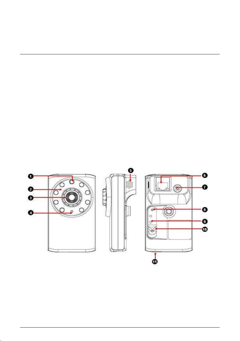
Camera components and functions
Light sensor
1.
The sensor is used to trigger on and off the Infrared LEDs according the
environmental light level.
2.
Infrared LEDs
The eight Infrared LEDs around the lens assembly allow your camera to capture
clear image in a dark environment.
5
Page 6

Lens assembly
3.
The lens assembly is equipped with a focus ring, allowing you to adjust the focus
manually to capture clear image.
4.
Built-in microphone
The internal microphone allows the camera to receive sound and voice on the
spot.
5.
Built-in speaker
The internal speaker allows the camera to broadcast sound and voice.
6.
Ethernet port
The port is used to connect the camera to your network via the Ethernet cable
(RJ-45 type). The port supports the NWay protocol so that the system will be able
to detect the network speed automatically.
DC 5V power input
7.
The power input connects the DC power adapter* to supply power to the camera.
Reset button
8.
Press the button to restart the camera.
Press and hold the button for 5 seconds to restore the factory default settings for
the camera.
9.
LED indicator
The LED indicator indicates the system status by:
Solid green light: the camera is connected to the AC power adapter and
powered on.
Flashing amber light: the camera is transmitting data through the network.
10.
WPS Button
Press the button to connect Wireless AP with WPS function
MicroSD card slot
11.
The slot allows you to insert a memory card for expansion of storage.
Hold the MicroSD card by the edges and gently insert it into the slot. To remove a
card, gently push the top edge of the card inwards to release it and then pull it out
of the slot.
6
Page 7

System requirements
When the camera is installed in your network for remote surveillance applications,
ensure the computer is in good network connection and meet system requirements as
below:
Minimum system requirement for connecting one camera
CPU: Pentium 4 class, 2.0GHz
Memory: 512MB RAM
Hard disk drive: 500MB of available space
GPU: AGP card, 128MB RAM; resolution @ 800x600 or above
Operating system: Microsoft Windows XP, Vista, and Win 7
Browser: Microsoft Internet Explorer 7.0 and above
Recommended system requirements for connecting multiple cameras
CPU: Intel Core 2 Duo, 2.0GHz
Memory: 2GB RAM or more
Hard disk drive: 500MB of available space
GPU: High performance graphic card, 256MB RAM or more; resolution @
1024x768 or above
Operating system: Microsoft Windows XP, Vista, and Win 7
Browser: Microsoft Internet Explorer 7.0 and above
Note: When you connect multiple cameras to monitor different places within your
surveillance application, it is recommended to use high-performance computer and
networking to approach better effect while transmitting the image.
Camera features
H.264, MPEG4 and MJPEG compression supported.
Built-in IR LEDs that provide truly Day&Night surveillance solution.
Built-in microphone and with 2-way audio function for listening/speaking through
the camera.
Capture high resolution video with the mega-pixel CMOS sensor.
Built-in 802.11 b/g/n WLAN **
Motion detection supported.
Advanced encryption mode to protect your camera with WPA2-PSK supported**.
Firmware upgradeable through the browser-based Configuration Utility.
7
Page 8
Chapter 2
Hardware and Software Installation
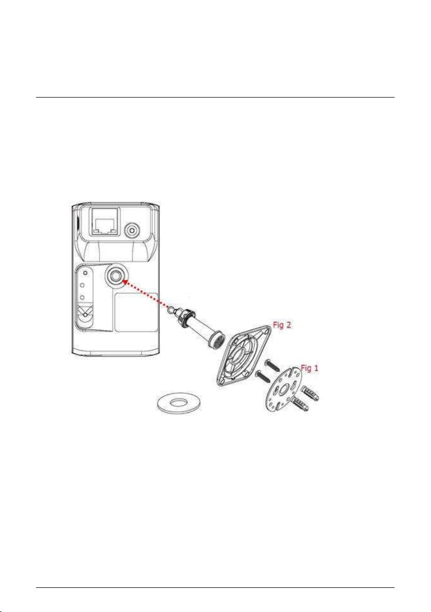
Installing the camera stand
The camera is designed with a camera stand hook-up located on the back panel.
Install the camera to the camera stand by screwing the swivel base to the hook-up,
and then you can mount the camera stand on the wall (or ceiling) through the two
screw holes*.
To mount the camera to a wall, unscrew the base of the camera and remove the metal
plate. With the included screws and anchors, fasten the base (Fig1) onto the wall with
screw, and then cover base with the base shell (Fig2) cover, finally will twist camera
tightly on the wall.
* The screw kit is included in the package
Note: To mount the camera on the wall (or ceiling) securely, it is recommended to use
the plastic wall anchors and screws.
8
Page 9
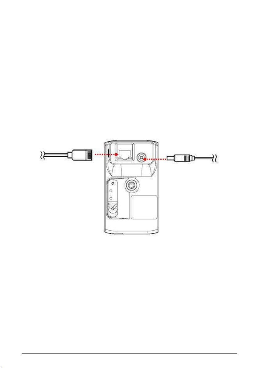
Connecting the cables
Connecting the Ethernet cable
Use the RJ-45 type Ethernet cable to connect the camera to your local area
network (LAN).
Plug one end of the Ethernet cable to the Ethernet port on the bottom panel of the
camera and the other end to an active port on the switch/router of the network.
Connecting the DC power adapter*
Plug the AC power adapter cable to the DC power input on the bottom panel of the
camera and the power plug to the wall socket.
The camera will be powered on automatically when you connect the AC power
adapter. The power status can be indicated from the LED on the back panel of the
camera.
Connecting the
Ethernet cable
Connecting the power
adapter
WPS Setup
Connect the DC power adapter to camera to power on. The power status can be
indicated from the LED indicator
1. After the WPS LED indicator unlighted, press the WPS button on your wireless
router or access point.
2. Press WPS button on the back of the camera. The camera will automatically
create a wireless connection to your router (around 30 seconds). While
connecting, the WPS LED indicator will blink quickly every 0.3 sec. If link
success, the LED will present steady red, otherwise slower blink every 1 sec.
3.
You can find camera listed in the camera table from SearchUtility tool installed
launched in your computer
and
9
Page 10
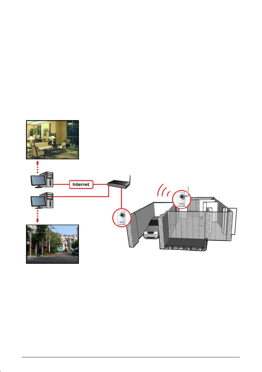
Applications of the Camera
The camera installed in your network can be applied in multiple applications, including:
Monitor different places, such as baby room/workshop, and objects remotely via
the Internet or Intranet.
Capture still images and record video clips.
Alert function that includes FTP upload and email messages.
The following explains how to set up the camera in the network and how does it work
in your surveillance applications.
router/switch
Home security solution
10
Page 11

Installing software
The camera setup wizard, CameraSetupWizard, that comes with your camera is a
convenient utility to search the connected camera within the network from your
computer.
To install the utility on your computer:
1.
Insert the Installation CD into the computer’s CD-ROM/DVD-ROM drive.
2.
The CD Menu should pop up automatically. Go into "Software/Utility" and double
click " CameraSetupWizard " to initiate the setup. Follow the prompts to complete
the installation.
3.
When done, the CameraSetupWizard icon will display on the desktop.
Double-click on the icon to launch the utility.
4.
From the Control Panel, you can:
Check the connected camera(s) from the Camera List, such as the IP Address,
Camera Name, Mac Address, and more.
Click Wizard to change the IP address of the selected camera.
Click Scan to search the camera within the network.
Click Connect IE to access the camera using Internet Explorer.
Click Exit to end the utility.
11
Page 12

Chapter 3
Managing the Camera
Setting up the camera’s networking by setup wizard
CameraSetupWizard tool lets you configure your camera’s networking easily and
quickly. The wizard will guide you through the necessary settings step-by-step.
1.
Launch CameraSetupWizard on your computer.
Select the camera you want and then click Wizard.
2.
3.
When prompted, enter the User Name and Password to access the camera. The
default User name is “admin” and the default password is “12345”.
Follow the prompts to complete the networking settings for the camera, including:
4.
select networking type (DHCP or Static IP)
configure wireless network (for wireless model only)
The diagrams below explain the wizard briefly:
For wireless model
5.
When done, re-connect the Ethernet cable and then click Scan again from the
wizard’s Control Panel.
Select networking type
Static IP
DHCP
Click Finish to complete
12
Page 13

Accessing the camera’s Configuration Utility
You can manage the camera via the computer’s Web browser easily. The following
sections will guide you through the basic and advanced settings of the camera by
using the browser-based Configuration Utility.
You can access the camera through CameraSetupWizard or via Internet Explorer:
1.
Access from CameraSetupWizard
Launch CameraSetupWizard. From the Camera List, select the desired
camera and then click Connect IE.
Access from Internet Explorer
Launch Internet Explorer. There are two access modes for different purpose.
Enter the camera’s IP address in the URL bar of the browser and then press
ENTER. The default IP address of the camera is “192.168.0.1”.
2.
Enter the User name and password in the Login window. The default User name
is “admin” and the default password is “12345”.
Note: If you are the first time to access the camera, it may be required to install a
plug-in for the camera. Permission request depends on the Internet security
settings of your computer. Follow the prompts to complete the plug-in installation.
3.
When you access the camera’s Configuration Utility, the Main screen will appear
as below:
13
Page 14

Using the Configuration Utility
The Main screen of the Configuration Utility provides you with many useful information
and functions, including the menus on the left column, the control buttons on the top of
the screen, and the Live View area for displaying the real-time video image. You can
also change the display language from the Language drop-down menu.
The menus
The menus contain the basic and advanced settings of the camera. Click the
desired button to display the menu screen.
Menu Description
Live View — Display the real-time video image of the connected
camera on the Main screen.
Network Setting — Change the network settings of the camera,
such as LAN, PPPoE, DDNS, and more.
Audio/Video Setting — Change the audio and video settings of the
camera.
Event Setting — Complete the required settings so that you can
upload images to FTP and send email messages by events.
System Setting — Change the camera’s basic settings. For
example, change the displayed camera name.
Record — Change the settings for recording.
Reboot — Restart the camera.
The control buttons
The control buttons allow you to control the camera’s function from the screen.
Button Description
Stream Change the stream to Master or Slave.
Snapshot
Audio In
Capture and save a still image*.
Enable or disable the microphone to receive the on-site sound
and voice from the camera.
Audio Out
Enable or disable the speaker to speak out via the camera.
* The folder that stores the captured image will be displayed on the screen for 2
seconds after you click the Snapshot button.
14
Page 15

Network Setting
LAN
This sub-menu allows you to select the IP address mode and set up the related
configuration.
- Ethernet Interface:
Select the Use DHCP option when your network uses the DHCP server. When
the camera starts up, it will be assigned an IP address from the DHCP server
automatically.
Otherwise, select the Use fixed IP address option to assign the IP address
for the camera directly, including IP Address, Subnet Mask, Gateway, DNS1,
and DNS2.
Option Description
IP Address
Subnet
Mask
Gateway
DNS1/2
When done, click Save.
Enter the IP address of the camera. The default setting is
“192.168.0.1”.
Enter the Subnet Mask of the camera. The default setting is
“255.255.255.0”.
Enter the default Gateway of the camera. The default setting
is “192.168.1.1”.
DNS translates domain names into IP addresses. Enter the
DNS1 (Primary DNS) and DNS2 (Secondary DNS) that are
provided by ISP (Internet Service Provider).
15
Page 16

WLAN
This sub-menu is available for wireless model only. Select On from the Wireless
Enable drop-down menu to enable this feature.
The available wireless network will be automatically displayed in the list. You can
search the wireless network manually by clicking Refresh.
- Wireless Setting:
When the wireless function is enabled, it is recommended to set the
authentication method for the wireless network to secure the camera from
being used by unauthorized user.
From the Security drop-down menu, select the proper option: Open, Shared,
WPA-PSK/TKIP, WPA-PSK/AES, WPA2-PSK/TKIP, or WPA2-PSK/AES.
Option Description
Open
The default setting of authentication mode, which
communicates the key across the network.
Shared
Allow communication between the devices with identical
WEP settings.
WPA-PSK/
WPA2-PSK
WPA-PSK/WPA2-PSK is specially designed for the users
who do not have access to network authentication servers.
The user has to manually enter the starting password in their
access point or gateway, as well as in each computer on the
wireless network.
Tip: TKIP (Temporal Key Integrity Protocol) changes the
temporal key every 10,000 packets to insure much greater
security than the standard WEP security. AES (Advanced
Encryption Standard) is used to ensure the highest degree of
security and authenticity for digital information.
16
Page 17

When the authentication method is set as Open or Shared, you need to select
the Default Key ID and then enter the WEP key(s) in the Key1/2/3/4 option.
When the authentication method is set as WPA-PSK or WPA2-PSK, you need
to enter the Shared Key that must match the Pre-shared key value in the
remote device.
The SSID (Network ID) keeps the default setting of this option to connect the
camera to any access point under the infrastructure network mode. To connect
the camera to a specified access point, set a SSID for the camera in the SSID
option to correspond with the access point’s ESS-ID. To connect the camera to
an Ad-Hoc wireless workgroup, set the same wireless channel and SSID to
match with the computer’s configuration.
When done, click Save.
PPPoE
This sub-menu is used when you use a direct connection via the ADSL modem.
Select the Enable option to enable this feature.
To activate PPPoE mode, you should have a PPPoE account from your Internet
service provider. Enter the User Name and Password (twice). The camera will get
an IP address from the ISP as starting up.
When done, click Save.
Filter
This sub-menu is used when you need to control access right in a certain IP
segment or specify the network communication protocol.
To add a designed filter, you should select the data packet access type of the
target and the communication protocol. Enter the Begin IP and End IP for dedicate
IP range. When done, click Add to append an item in your filter list.
When done, click Save.
17
Page 18

DDNS
This sub-menu allows you to assign a fixed host and domain name to a dynamic
Internet IP address. Select the Enable option to enable this feature.
Note: You need to sign up for DDNS service with the service provider before
configuring this feature and accessing the server.
To set up the DDNS:
b. Select the DDNS Service type.
c. Select the Interface.
d. Enter the required information in the Host Name, User Name, and Password
options.
e. When done, click Save.
NTP
This sub-menu lets you set the correct date and time for the camera.
- Synchronized with Time Server:
Select the option and the time will be synchronized with the NTP Server. Then,
select the proper Time Zone for the region from the drop-down menu and
enable or disable Daylight Saving.
18
Page 19

- Manual Update:
You can also enter the date and time manually by selecting the option.
- Synchronized with PC:
Select the option and the date/time settings of the camera will be synchronized
with the connected computer.
When done, click Save.
UPnP
This sub-menu allows you to enable of disable the UPnP function for the camera.
Select the Enable option to enable this function.
The UPnP (Universal Plug and Play) function is a set of computer network
protocols that enable the device-to-device interoperability. It also supports port
auto mapping function so that you can access the camera if it is behind an NAT
router or firewall.
- Discovery Available:
Select the option and the camera will be able to announce to control points that
it has become available on the network.
When done, click Save.
Audio/Video Setting
General Settings
This sub-menu allows you to set up the audio function for the camera
19
Page 20

- Audio Format:
From the drop-down menu, set the encoding laws as A law (a-law), μ law
(u-law) or ACC. The A law option is usually used in European PCM systems
and the μ law option is used in American PCM systems.
- OSD Timer:
Select the ON or OFF option from the drop-down menu to display or hide the
date & time information on the live view image.
- Resolution Max.:
From the drop-down menu, select the maximum resolution as 720P(1280x720).
This camera provides 3 streams simultaneously.
- Stream Selection Area:
From the drop-down menu, select to transmit and record the video using
MPEG4, MJPEG or H.264 compression.
Option Description
MPEG4
Select the option and then you can determine the video
streaming by Fixed Bit Rate or Quality.
Once you change the compression mode to/from MPEG4,
you need to restart the system.
MJPEG
Select the option and then you can determine the video
streaming by Quality.
H.264
Select the option and then you can determine the video
streaming by Fixed Bit Rate or Quality.
You also need to set the proper Resolution and Frame Rate depending on
your network status. Please note that higher setting obtains better video quality
while it uses more resource within your network.
20
Page 21

Note: The camera supports H.264, MPEG4 and MJPEG compression. The
MJPEG mode captures the images in JPEG format, requiring higher bandwidth
to view smooth video. You should control the bandwidth of each connection
well through the setting options above.
When done, click Save.
Speaker Volume Settings
This sub-menu allows you to adjust the speaker volume settings.
- Speaker Volume:
In the field, you can set the speaker’s volume from value -41 to 3.
When done, click Save.
Image Settings
This sub-menu allows you to change the image related settings.
- Image Adjustment:
In the field, you can set the image’s Brightness, Contrast, Saturation, and
Sharpness from the corresponding drop-down menus.
Option Description
Brightness
Adjust the brightness level from 0 ~ 9. The default setting is
5.
Contrast
Adjust the contrast level from 0 ~ 3. The default setting is 0.
21
Page 22

Saturation
Adjust the saturation level from 0 ~ 9. The default setting is
4.
Sharpness
Adjust the sharpness level from 0 ~ 9. The default setting is
4.
- Video Orientation:
In the field, the Mirror / Flip option allow you to mirror the image horizontally /
vertically. Select the ON or OFF option from corresponding drop-down menu to
enable or disable the function.
- Enhancement:
The images that are not properly corrected may look either bleached out or too
dark. From the Gamma Correct drop-down menu, select the proper value to
fix the overall brightness of the image.
The Power Line Frequency option allows you to select the proper frequency
according to the camera’s location: 50 or 60 Hz. This option is used to reduce
the noise of image.
Click Default to restore the factory default for the settings above.
Private Settings
This sub-menu allows you to set privacy mask window. All user can not view the
block under privacy mask window.
- Mask:
Check this option to turn on/off privacy mask of the specified window.
- Reset Mask Area On:
Check on these bullet boxes to draw a privacy mask. Use the mouse to click, hold
and drag the window frame to resize. Uncheck the bullet box to delete the privacy
mask window.
When done, click Save.
22
Page 23

Event Setting
Motion Detection
This sub-menu allows you to set up the motion detection feature of the camera.
The camera buffer a 10 seconds pre-record stream. This stream can be record to
SD card or network storage.
The camera provides three detecting areas. To activate the detecting area, select
the Enable option in the Window 1/2/3 fields. When the detecting area is activated,
select the desired window and then you can use the mouse to move the detecting
area and change the area coverage.
- Sensitivity:
Select the value from the drop-down menu to increase or decrease the
sensitivity of motion detection. The higher value indicates the higher sensitivity.
- Threshold:
Select the value from the drop-down menu to adjust the level for detecting
motion to record video. The higher value indicates the higher threshold.
- Interval:
23
Page 24

Assign specific recording seconds of the video clip when motion detection
triggered.
- Send To:
Select the destination to send or store for video clip from the drop-down menu.
When done, click Save.
FTP
This sub-menu allows you set up the FTP server so the camera will be able to
upload images per events.
To set up the FTP server, complete the required settings in the FTP field, including:
Server, Port, User, Password, Remote Folder, and Passive Mode.
Option Description
Server
Port
Enter the IP address of the target FTP server.
Enter the port number that is assigned for the FTP server.
The default FTP port is 21.
User
Password
Remote Folder
Enter the user name to login the FTP server.
Enter the password to login the FTP server.
Enter the destination folder for uploading the images.
Example: /Test/
Passive Mode Select the Enable option to enable passive mode.
When done, click Save.
SMTP
This sub-menu allows you set up the SMTP server so the camera will be able to
send email messages per events.
24
Page 25

To set up the SMTP server, complete the required settings in the FTP field,
including: Server, Port, Connection Security, Recipient, User, and Password.
Option Description
Server
Enter the mail server address.
Example: yourmail.com
Port Assign the SMTP port. The default SMTP port is 25.
Connection
Security
Recipient
Select None, STARTTLS, or SSL/TLS according to the
mail server’s configuration.
Enter the email address of the user who will receive the
notification message.
User
Password
Enter the user name to login the mail server.
Enter the password to login the mail server.
When done, click Save.
Record
Setting
This sub-menu allows you to configure the recording settings.
25
Page 26

- Video Streaming:
From the drop-down menu, select the video streaming as Master mode or
Slave mode.
- Recording Storage:
The recorded video files will be stored to the MicroSD card (when it is inserted).
The status of the inserted MicroSD card will be displayed in the Storage
Space field.
- Auto clean old data:
Select the option so the system will delete the old files when the storage space
of the MicroSD card is less than 10%.
- Simple Recording Mode:
Simply click the Start button to start recording and click the Start button again
to stop recording.
- Advance Recording Mode:
From the drop-down menu, select the recording mode.
When done, click Save.
List
This sub-menu displays the list of the recorded video of the camera.
Network Drive
This sub-menu allows you to set the network storage configuration. Check Enable
box to enable this function.
26
Page 27

- Server:
Specify the shared network storage server
- System Type:
Choose the server’s OS system from the drop down menu.
- Share Folder:
Assign the path to upload the media
- User Name:
Grant user name on the network storage
- Password:
Grant password on the network storage
When done, click Save.
27
Page 28

System Setting
Information
This menu displays the current configuration of the camera.
Basic
This sub-menu lets you manage the port numbers and camera name for the
camera.
- Unicast Start/End port:
Set the start port and end port for the unicast service of the camera. The
default start port is 5000 and the end port is 6000.
- RTSP Port:
28
Page 29

Set the transmission of streaming data within the network. The default RTSP
(Real Time Streaming Protocol) port is 554.
RTSP is a technology that allows you to view streaming media via the network.
You can view the real-time video using Quick Time player or RealPlayer. To
view the real-time streaming video on your computer, open the Web browser
and then enter the RTSP link (for example, rtsp://camera’s IP address/live/0).
The number here stands for different stream resolution: 0 for HD, 1 for VGA, 2
for QVGA
- HTTP Port:
Enter the HTTP port for the camera. The default setting is 80.
- Camera Name:
This box lets you enter a descriptive name for the camera in the Camera
Name option. This is helpful to identify the camera easily while multiple
cameras are connected within the network.
When done, click Save.
Advanced
This menu allows you to set up the schedule for recording.
- Day/Night Mode:
Enter the From the drop-down menu, select the Disable option to disable the
trigger function or select the Trigger by schedule option to set up the
schedule profile for the camera.
- Duration:
From the drop-down menu, specifies the schedule time interval by hours.
- Hour/Active:
In this field, select the time period that you want to assign for the recording
schedule. The assigned time period will be displayed with a check mark.
29
Page 30

When done, click Save.
Account
This sub-menu lets you manage the users for the camera.
- Add New User:
In the User Name option, enter the user’s name you want to add to use the
camera. Then, enter the Password (twice) for the new user.
When done, click Add.
- Delete User or Reset User Password:
You can manage the users for the camera by removing the user or changing
the account’s password. From the User List drop-down menu, select the
desired user and then click Remove to delete the account, or enter the new
password (twice) to change the account’s password.
When done, click Update.
- Change Password:
To prevent unauthorized access to the camera’s Configuration Utility, you are
strongly recommend to change the default administrator password. Enter the
new password (twice) to reset and confirm the administrator’s password.
When done, click Update.
Change Password
To prevent unauthorized access to the camera’s Configuration Utility, you are
strongly recommend to change the default administrator password. Enter the new
password to reset and then confirm the administrator’s password.
Firmware Update
This menu displays the current configuration of the camera.
When done, click Update.
30
Page 31

To upgrade your camera to the latest firmware (if available), click Browse to locate
the firmware file and then click Upgrade.
Note: Ensure to keep the camera connected to the power source during the process of
upgrading firmware.
Backup
This menu allows you to save the current configuration of the camera.
- Backup:
To backup the current configuration of your camera, click the Backup button to
save the configuration to a specified file.
- Restore:
To restore the previous configuration of your camera (if available), click
Browse to locate the configuration file and then click Restore.
Reset
This menu allows you to soft reset the configuration of the camera to the default
value.
Click Reset. The system will reset the configuration of the camera to the default
value.
Authentication
This sub-menu lets you set the security for the camera.
31
Page 32

- Authentication Mode:
Select the Enable of Disable option to enable or disable the security for the
camera.
- Number of Connections:
From the drop-down menu, select the number of users (from 1 to 10) that are
allowed to access the camera simultaneously.
When done, click Save.
Reboot
Reboot
This menu lets you restart the camera just like turning the device off and on.
Click Reboot. The system will keep the configuration status after rebooting.
32
Page 33

Appendix
Specifications
Model CAM1215
Image sensor
Lens
Electronic shutter
Min. illumination
Bulit-in IR LEDs (automatic illumination < 5 lux)
Video
compression
Video resolution
Stream bit rate
Audio format
Audio input
Audio output
LAN
WLAN
Protocol
TCP, UDP, IP, HTTP, FTP, SMTP, DHCP, DNS, DDNS, ARP,
ICMP, IGMP, RTP, RTSP, 3GPP
LED indicator
Storage
RTC support
Software support
Power input
Power
consumption
Operational
temperature
Operational
humidity
Storage
temperature
1/4" progressive CMOS sensor
Fixed focal length: 4.2 mm
Auto
0 lux (with IR LEDs activated);
H.264 / M-JPEG
Stream 1: 1280x720
Stream 2: 640x480,
Stream 3: 640x480
16 Kbps~4 Mbps, VBR or CBR
G.711μ-Law / G.711a-Law/AAC
G.711μ-Law
Built-in microphone
Built-in Mic
10/100Mbps Ethernet, RJ-45
11N, 1T1R antenna
Green: Power
Orange: Wireless Connection
MicroSD card Slot x 1
Yes
Operating system: Windows XP/Vista, and Win 7
Browser: Internet Explorer 7.0 and above
5.0 VDC
4.0W
0ºC ~ +40ºC
RH85% or less
-20ºC ~ +70ºC
33
Page 34

Dimension (mm)
Weight
Emission
Configuring the IP Address of the computer
100(L) x 56 (W) x 40 (D)
80.0 g
CE, FCC
The camera’s default IP address is “192.168.1.2”. If you cannot access the camera by
entering the default IP address froom the browser, check the settings of your computer.
When you connect the camera to your computer directly to configure the camera, you
have to set the computer’s IP address to be in the same segment as the camera’s to
communicate.
1.
On your computer, click Start Control Panel to open the Control Panel window.
2.
Double-click Network Connection to open the Network Connection window.
Right-click Local Area Connection and then click Properties from the shortcut
3.
menu.
4.
When the Local Area Connection Properties window appears, select the General
tab.
5.
Select Internet Protocol [TCP/IP] and then click Properties to bring up the
Internet Protocol [TCP/IP] Properties window.
6.
To configure a fixed IP address that is within the segment of the camera, select the
Use the following IP address option. Then, enter an IP address into the empty
field. The suggested IP address is “192.168.0.X” (X is 2~254), and the suggested
Subnet mask is “255.255.255.0”.
7.
When done, click OK.
34
Page 35

Warnings:
This device complies with part 15 of the FCC Rules. Operation is subject to the
following two conditions: (1) This device may not cause harmful interference,
and (2) this device must accept any interference received, including
interference that may cause undesired operation.
Any Changes or modifications not expressly approved by the party responsible for
compliance could void the user's authority to operate the equipment.
Note: This equipment has been tested and found to comply with the limits for a
Class B digital device, pursuant to part 15 of the FCC Rules. These limits are
designed to provide reasonable protection against harmful interference in a
residential installation. This equipment generates uses and can radiate radio
frequency energy and, if not installed and used in accordance with the instructions,
may cause harmful interference to radio communications. However, there is no
guarantee that interference will not occur in a particular installation. If this
equipment does cause harmful interference to radio or television reception, which
can be determined by turning
the equipment off and on, the user is encouraged to try to correct the interference
by one or more of the following measures:
-Reorient or relocate the receiving antenna.
-Increase the separation between theequipment and receiver.
-Connect the equipment into an outlet on a circuit different from that to which
the receiver is connected.
-Consult the dealer or an experienced radio/TV technician for help.
FCC RF exposure :
This equipment complies with FCC radiation exposure limits set forth for anuncontrolled en
vironment. This equipment should be installed and operated withminimum distance 20cm
between the radiator & your body.
35
 Loading...