

Page 1

User’s Guide
MGS3600-24F/XGS3600-26F/XGS3600-28F
Page 2

MGS3600-24F/XGS3600-26F/XGS3600-28F USER’S GUIDE ABOUT THIS USER’S GUIDE
Note:
About This User’s Guide
Intended Audience
This manual is intended for people who want to configure the switch using the web configurator.
Related Documents
Command Line Interface (CLI) Reference Guide
The Command Reference Guide explains how to use the Command-Line Interface (CLI) and CLI commands to configure the switch.
Web Configurator Online Help
The embedded Web Help contains descriptions of individual screens and supplementary information.
It is recommended you use the web configurator to configure the switch.
Support Disc
Refer to the included CD for support documents.
Documentation Feedback
Send your comments, questions or suggestions to: techwriters@zyxel.com.tw
Thank you!
II
Page 3

MGS3600-24F/XGS3600-26F/XGS3600-28F USER’S GUIDE ABOUT THIS USER’S GUIDE
The Technical Writing Team, ZyXEL Communications Corp.,
6 Innovation Road II, Science-Based Industrial Park, Hsinchu, 30099, Taiwan.
Need More Help?
More help is available at www.zyxel.com.
Download Library
Search for the latest product updates and documentation from this link. Read the Tech Doc Overview to find out how to efficiently use the
User Guide, Quick Start Guide and Command Line Interface Reference Guide in order to better understand how to use your product.
Knowledge Base
If you have a specific question about your product, the answer may be here. This is a collection of answers to previously asked questions
about ZyXEL products.
Forum
This contains discussions on ZyXEL products. Learn from others who use ZyXEL products and share your experiences as well.
Customer Support
Should problems arise that cannot be solved by the methods listed above, you should contact your vendor . If you cannot cont act your vendor, then
contact a ZyXEL office for the region in which you bought the device.
See http://www.zyxel.com/web/contact_us.php for contact information. Please have the following information ready when you contact an office.
Product model and serial number.
Warranty Information.
III
Page 4

MGS3600-24F/XGS3600-26F/XGS3600-28F USER’S GUIDE ABOUT THIS USER’S GUIDE
Date that you received your device.
Brief description of the problem and the steps you took to solve it.
IV
Page 5

MGS3600-24F/XGS3600-26F/XGS3600-28F USER’S GUIDE DOCUMENT CONVENTIONS
WARNING:
Note:
Document Conventions
Warnings and Notes
These are how warnings and notes are shown in this User’s Guide.
Warnings tell you about things that could harm you or your device.
Notes tell you other important information (for example, other things you may need to configure or helpful tips) or recommendations.
Syntax Conventions
The MGS3600-24F, XGS3600-26F and XGS3600-26F may be referred to as the “MGS3600-24F”, “XGS3600-26F”, “XGS3600-28F”,
“switch”, the “device”, the “system” or the “product” in this User’s Guide. Differentiation is made where needed.
Product labels, screen names, field labels and field choices are all in bold font.
A key stroke is denoted by square brackets and uppercase text, for example, [ENTER] means the “enter” or “return” key on your keyboard.
“Enter” means for you to type one or more characters and then press the [ENTER] key . “Select” or “choose” means for you to use one of the
A right angle bracket ( > ) within a screen name denotes a mouse click. For example, Maintenance > Log > Log Setting means you first click
Units of measurement may denote the base-10 value or the base-2 value. For example, “k” for kilo may denote “1000” or “1024”, “M” for
predefined choices.
Maintenance in the navigation panel, then the Log sub menu and finally the Log Setting tab to get to that screen.
mega may denote “1000000” or “1048576” and so on.
V
Page 6
MGS3600-24F/XGS3600-26F/XGS3600-28F USER’S GUIDE DOCUMENT CONVENTIONS
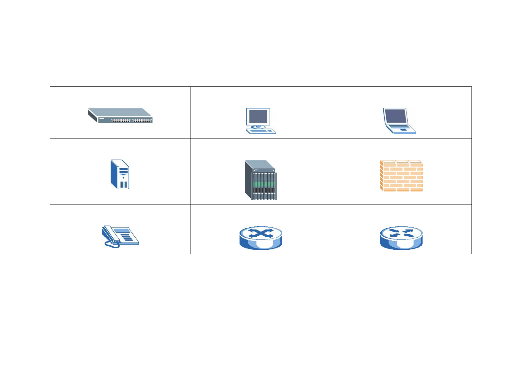
Icons Used in Figures
Figures in this User’s Guide may use the following generic icons. The switch icon is not an exact representation of your device.
The Switch Computer Notebook computer
Server DSLAM Firewall
Telephone Switch Router
VI
Page 7

MGS3600-24F/XGS3600-26F/XGS3600-28F USER’S GUIDE SAFETY WARNINGS
Safety Warnings
Do NOT use this product near water, for example, in a wet basement or near a swimming pool.
Do NOT expose your device to dampness, dust or corrosive liquids.
Do NOT store things on the device.
Do NOT install, use, or service this device during a thunderstorm. There is a remote risk of electric shock from lightning.
Connect ONLY suitable accessories to the device.
Do NOT open the device or unit. Opening or removing covers can expose you to dangerous high voltage points or other risks. ONLY quali-
fied service personnel should service or disassemble this device. Please contact your vendor for further information.
For continued protection against risk of fire replace only with same type and rating of fuse.
Make sure to connect the cables to the correct ports.
Place connecting cables carefully so that no one will step on them or stumble over them.
Always disconnect all cables from this device before servicing or disassembling.
Use ONLY an appropriate power adaptor or cord for your device. Connect it to the right supply voltage (for example, 110V AC in North
America or 230V AC in Europe).
Do NOT allow anything to rest on the power adaptor or cord and do NOT place the product where anyone can walk on the power adaptor or
cord.
Do NOT use the device if the power adaptor or cord is damaged as it might cause electrocution.
If the power adaptor or cord is damaged, remove it from the device and the power source.
Do NOT attempt to repair the power adaptor or cord. Contact your local vendor to order a new one.
Do not use the device outside, and make sure all the connections are indoors. There is a remote risk of electric shock from lightning.
Do NOT obstruct the device ventilation slots, as insufficient airflow may harm your device.
VII
Page 8

MGS3600-24F/XGS3600-26F/XGS3600-28F USER’S GUIDE SAFETY WARNINGS
Your product is marked with this symbol, which is known as the WEEE mark. WEEE stands for Waste Electronics and Electrical
Equipment. It means that used electrical and electronic product
s should not be mixed with general waste. Used electrical and elec-
tronic equipment should be treated separately.
VIII
Page 9

MGS3600-24F/XGS3600-26F/XGS3600-28F USER’S GUIDE
CONTENTS OVERVIEW
Front Matter
Front Matter
Introduction....................................................................................................................................................................1-2
Ways to Manage the Switch..........................................................................................................................................1-3
Good Habits for Managing the Switch...........................................................................................................................1-4
Front Matter
Free Standing Installation..............................................................................................................................................2-2
Rack-Mounted Installation.............................................................................................................................................2-4
Rack-mounted Installation Requirements..................................................................................................................2-4
Precautions ............................................................................................................................................................2-4
Attaching the Mounting Brackets to the Switch..........................................................................................................2-5
Mounting the Switch on a Rack..................................................................................................................................2-6
Front Matter
IX
Page 10

MGS3600-24F/XGS3600-26F/XGS3600-28F USER’S GUIDE
Front Panel Connections...............................................................................................................................................3-2
Dual Personality Interfaces........................................................................................................................................3-5
1000Base-T Ports......................................................................................................................................................3-6
Default Ethernet Settings .......................................................................................................................................3-6
Mini-GBIC Slots..........................................................................................................................................................3-7
Transceiver Installation .........................................................................................................................................3-8
Transceiver Removal .............................................................................................................................................3-9
Power Connectors......................................................................................................................................................3-10
Console Port ..............................................................................................................................................................3-12
LEDs ..........................................................................................................................................................................3-13
Front Matter
Overview........................................................................................................................................................................4-2
Traffic Overview.............................................................................................................................................................4-3
Status: Port Details........................................................................................................................................................4-5
Front Matter
Overview........................................................................................................................................................................5-2
X
Page 11

MGS3600-24F/XGS3600-26F/XGS3600-28F USER’S GUIDE
What You Can Do......................................................................................................................................................5-3
System Information........................................................................................................................................................5-4
General Setup................................................................................................................................................................5-7
VLANs............................................................................................................................................................................5-10
IP Setup.........................................................................................................................................................................5-12
Management IP Addresses........................................................................................................................................5-12
Port Configuration..........................................................................................................................................................5-15
Front Matter
Front Matter
System Configuration ....................................................................................................................................................6-5
System Information........................................................................................................................................................6-6
Information.................................................................................................................................................................6-6
Configuration..............................................................................................................................................................6-9
CPU Load...................................................................................................................................................................6-10
Time...............................................................................................................................................................................6-11
Manual .......................................................................................................................................................................6-11
XI
Page 12

MGS3600-24F/XGS3600-26F/XGS3600-28F USER’S GUIDE
NTP............................................................................................................................................................................6-13
Account..........................................................................................................................................................................6-14
Users..........................................................................................................................................................................6-14
Privilege Level............................................................................................................................................................6-16
IP ...................................................................................................................................................................................6-17
IPv4............................................................................................................................................................................6-17
IPv6............................................................................................................................................................................6-19
SYSLOG........................................................................................................................................................................6-20
Configuration..............................................................................................................................................................6-20
Log.............................................................................................................................................................................6-21
Detailed Log...............................................................................................................................................................6-22
SNMP ............................................................................................................................................................................6-23
System.......................................................................................................................................................................6-23
Communities..............................................................................................................................................................6-24
Users..........................................................................................................................................................................6-25
Groups .......................................................................................................................................................................6-27
Views..........................................................................................................................................................................6-28
XII
Page 13

MGS3600-24F/XGS3600-26F/XGS3600-28F USER’S GUIDE
Access........................................................................................................................................................................6-29
Trap............................................................................................................................................................................6-31
Front Matter
Configuration .................................................................................................................................................................7-2
Port................................................................................................................................................................................7-3
Configuration..............................................................................................................................................................7-3
Port Description..........................................................................................................................................................7-5
Traffic Overview.........................................................................................................................................................7-6
Detailed Statistics.......................................................................................................................................................7-7
QoS Statistics.............................................................................................................................................................7-9
SFP Information.........................................................................................................................................................7-10
ACL................................................................................................................................................................................7-12
Ports...........................................................................................................................................................................7-12
Rate Limiters..............................................................................................................................................................7-14
Access Control List ....................................................................................................................................................7-15
ACL Status.................................................................................................................................................................7-21
Aggregation ...................................................................................................................................................................7-23
XIII
Page 14

MGS3600-24F/XGS3600-26F/XGS3600-28F USER’S GUIDE
Static Trunk................................................................................................................................................................7-23
LACP..........................................................................................................................................................................7-25
Spanning Tree...............................................................................................................................................................7-29
Bridge Settings...........................................................................................................................................................7-30
MSTI Mapping............................................................................................................................................................7-32
MSTI Priorities............................................................................................................................................................7-33
CIST Ports..................................................................................................................................................................7-34
MSTI Ports.................................................................................................................................................................7-36
Bridge Status..............................................................................................................................................................7-37
Port Status .................................................................................................................................................................7-39
Port Statistics.............................................................................................................................................................7-40
MRSTP..........................................................................................................................................................................7-41
Instances....................................................................................................................................................................7-41
Port Configuration......................................................................................................................................................7-44
Port Status .................................................................................................................................................................7-46
IGMP and MLD Snooping..............................................................................................................................................7-48
Basic Configuration............................................................................................................
XIV
........................................7-48
Page 15

MGS3600-24F/XGS3600-26F/XGS3600-28F USER’S GUIDE
VLAN Configuration ...................................................................................................................................................7-50
Port Group Filtering....................................................................................................................................................7-52
Status.........................................................................................................................................................................7-53
Group Information......................................................................................................................................................7-55
IPv4 and IPv6 SSM Information.................................................................................................................................7-56
MVR...............................................................................................................................................................................7-57
Configuration..............................................................................................................................................................7-57
Groups Information ....................................................................................................................................................7-59
Statistics.....................................................................................................................................................................7-60
LLDP..............................................................................................................................................................................7-61
LLDP Configuration....................................................................................................................................................7-61
LLDP Neighbors.........................................................................................................................................................7-64
LLDP MED Configuration...........................................................................................................................................7-65
LLDP MED Neighbors................................................................................................................................................7-71
Port Statistics.............................................................................................................................................................7-74
Configuration..............................................................................................................................................................7-76
Dynamic MAC Table..............................................................................................................
XV
....................................7-78
Page 16

MGS3600-24F/XGS3600-26F/XGS3600-28F USER’S GUIDE
VLAN .............................................................................................................................................................................7-79
VLAN Membership.....................................................................................................................................................7-79
Ports...........................................................................................................................................................................7-80
Switch Status .............................................................................................................................................................7-82
Port Status .................................................................................................................................................................7-83
Private VLANs............................................................................................................................................................7-84
MAC-Based VLAN .....................................................................................................................................................7-86
Protocol-Based VLAN................................................................................................................................................7-88
GARP and MRP.............................................................................................................................................................7-90
Configuration..............................................................................................................................................................7-90
Statistics.....................................................................................................................................................................7-92
GVRP and MVRP..........................................................................................................................................................7-93
Configuration..............................................................................................................................................................7-93
Statistics.....................................................................................................................................................................7-95
QoS................................................................................................................................................................................7-96
Port Classification ......................................................................................................................................................7-96
Port Policing...............................................................................................................................................................7-99
XVI
Page 17

MGS3600-24F/XGS3600-26F/XGS3600-28F USER’S GUIDE
Queue Policing...........................................................................................................................................................7-101
Port Scheduler and Port Shaping...............................................................................................................................7-102
Port Tag Remarking...................................................................................................................................................7-104
Port DSCP..................................................................................................................................................................7-106
DSCP Based QoS......................................................................................................................................................7-107
DSCP Translation ......................................................................................................................................................7-108
DSCP Classification...................................................................................................................................................7-109
QoS Control List.........................................................................................................................................................7-110
QCL Status.................................................................................................................................................................7-114
WRED........................................................................................................................................................................7-116
sFlow Agent...................................................................................................................................................................7-118
Collector.....................................................................................................................................................................7-118
Sampler......................................................................................................................................................................7-120
Mirroring.........................................................................................................................................................................7-121
Trap Event Severity.......................................................................................................................................................7-122
SMTP Configuration ......................................................................................................................................................7-123
802.3ah OAM....................................................................................................................
XVII
.............................................7-124
Page 18

MGS3600-24F/XGS3600-26F/XGS3600-28F USER’S GUIDE
Port Config.................................................................................................................................................................7-124
Event Config...............................................................................................................................................................7-126
Port Status .................................................................................................................................................................7-128
Link Events.................................................................................................................................................................7-130
Statistics.....................................................................................................................................................................7-133
Ethernet OAM................................................................................................................................................................7-135
EPS................................................................................................................................................................................7-137
EPRS.............................................................................................................................................................................7-139
Security
Security..........................................................................................................................................................................8-2
IP Source Guard............................................................................................................................................................8-3
Configuration..............................................................................................................................................................8-3
Static Table................................................................................................................................................................8-4
Dynamic Table...........................................................................................................................................................8-5
ARP Inspection..............................................................................................................................................................8-6
Configuration..............................................................................................................................................................8-6
Static Table................................................................................................................................................................8-7
XVIII
Page 19

MGS3600-24F/XGS3600-26F/XGS3600-28F USER’S GUIDE
Dynamic Table...........................................................................................................................................................8-8
DHCP Snooping ............................................................................................................................................................8-9
Configuration..............................................................................................................................................................8-9
Statistics.....................................................................................................................................................................8-10
DHCP Relay ..................................................................................................................................................................8-12
Configuration..............................................................................................................................................................8-12
Statistics.....................................................................................................................................................................8-13
NAS ...............................................................................................................................................................................8-15
Configuration..............................................................................................................................................................8-15
Switch Status .............................................................................................................................................................8-22
Port Status .................................................................................................................................................................8-23
AAA................................................................................................................................................................................8-25
Configuration..............................................................................................................................................................8-25
RADIUS Overview......................................................................................................................................................8-28
RADIUS Details..........................................................................................................................................................8-29
Port Security..................................................................................................................................................................8-33
Limit Control...............................................................................................................................................................8-33
XIX
Page 20

MGS3600-24F/XGS3600-26F/XGS3600-28F USER’S GUIDE
Switch Status .............................................................................................................................................................8-36
Port Status .................................................................................................................................................................8-38
Access Management.....................................................................................................................................................8-40
Configuration..............................................................................................................................................................8-40
Statistics.....................................................................................................................................................................8-42
SSH ...............................................................................................................................................................................8-43
HTTPS...........................................................................................................................................................................8-44
AUTH Method................................................................................................................................................................8-45
Maintenance
Restart Device...............................................................................................................................................................9-2
Firmware........................................................................................................................................................................9-3
Firmware Upgrade .....................................................................................................................................................9-3
Firmware Selection ....................................................................................................................................................9-4
Save/Restore.................................................................................................................................................................9-5
Factory Defaults.........................................................................................................................................................9-5
Save Start ..................................................................................................................................................................9-6
Save User ..................................................................................................................................................................9-7
XX
Page 21

MGS3600-24F/XGS3600-26F/XGS3600-28F USER’S GUIDE
Restore User..............................................................................................................................................................9-8
Export/Import.................................................................................................................................................................9-9
Export Config .............................................................................................................................................................9-9
Import Config..............................................................................................................................................................9-10
Diagnostics....................................................................................................................................................................9-11
Ping............................................................................................................................................................................9-11
Ping6..........................................................................................................................................................................9-12
Front Matter
Front Matter
Power, Hardware Connections and LEDs.....................................................................................................................10-3
Switch Access and Login...............................................................................................................................................10-4
Switch Configuration......................................................................................................................................................10-6
Front Matter
Hardware Specifications................................................................................................................................................11-2
Firmware Specifications.................................................................................................................................................11-7
XXI
Page 22

MGS3600-24F/XGS3600-26F/XGS3600-28F USER’S GUIDE
EMI/Safety Specifications..............................................................................................................................................11-19
Front Matter
Glossary of Web Based Management...........................................................................................................................A-1
Common Services .........................................................................................................................................................B-1
Legal Information...........................................................................................................................................................C-1
XXII
Page 23

MGS3600-24F/XGS3600-26F/XGS3600-28F USER’S GUIDE
TABLE OF CONTENTS
About This User’s Guide
Intended Audience.........................................................................................................................................................ii
Related Documents.......................................................................................................................................................ii
Documentation Feedback..............................................................................................................................................ii
Customer Support..........................................................................................................................................................iii
Document Conventions
Safety Warnings
Front Matter
Front Matter
Introduction....................................................................................................................................................................1-2
XXIII
Page 24

MGS3600-24F/XGS3600-26F/XGS3600-28F USER’S GUIDE
Ways to Manage the Switch..........................................................................................................................................1-3
Good Habits for Managing the Switch...........................................................................................................................1-4
Front Matter
Free Standing Installation..............................................................................................................................................2-2
Rack-Mounted Installation.............................................................................................................................................2-4
Rack-mounted Installation Requirements..................................................................................................................2-4
Precautions ............................................................................................................................................................2-4
Attaching the Mounting Brackets to the Switch..........................................................................................................2-5
Mounting the Switch on a Rack..................................................................................................................................2-6
Front Matter
Front Panel Connections...............................................................................................................................................3-2
Dual Personality Interfaces........................................................................................................................................3-5
1000Base-T Ports......................................................................................................................................................3-6
Default Ethernet Settings .......................................................................................................................................3-6
Mini-GBIC Slots..........................................................................................................................................................3-7
Transceiver Installation .........................................................................................................................................3-8
XXIV
Page 25

MGS3600-24F/XGS3600-26F/XGS3600-28F USER’S GUIDE
Transceiver Removal .............................................................................................................................................3-9
Power Connectors......................................................................................................................................................3-10
AC Power Connection ........................................................................................................................................3-10
DC Power Connection........................................................................................................................................3-11
Console Port ..............................................................................................................................................................3-12
LEDs ..........................................................................................................................................................................3-13
Front Matter
Overview........................................................................................................................................................................4-2
Traffic Overview.............................................................................................................................................................4-3
Status: Port Details........................................................................................................................................................4-5
Front Matter
Overview........................................................................................................................................................................5-2
What You Can Do......................................................................................................................................................5-3
System Information........................................................................................................................................................5-4
General Setup................................................................................................................................................................5-7
VLANs............................................................................................................................................................................5-10
XXV
Page 26

MGS3600-24F/XGS3600-26F/XGS3600-28F USER’S GUIDE
IP Setup.........................................................................................................................................................................5-12
Management IP Addresses........................................................................................................................................5-12
Port Configuration..........................................................................................................................................................5-15
Front Matter
Front Matter
System Configuration ....................................................................................................................................................6-5
System Information........................................................................................................................................................6-6
Information.................................................................................................................................................................6-6
Parameter description.........................................................................................................................................6-6
Configuration..............................................................................................................................................................6-9
Parameter description.........................................................................................................................................6-9
CPU Load...................................................................................................................................................................6-10
Time...............................................................................................................................................................................6-11
Manual .......................................................................................................................................................................6-11
Parameter description.........................................................................................................................................6-11
NTP............................................................................................................................................................................6-13
XXVI
Page 27

MGS3600-24F/XGS3600-26F/XGS3600-28F USER’S GUIDE
Parameter description.........................................................................................................................................6-13
Account..........................................................................................................................................................................6-14
Users..........................................................................................................................................................................6-14
Parameter description.........................................................................................................................................6-14
Privilege Level............................................................................................................................................................6-16
Parameter description.........................................................................................................................................6-16
IP ...................................................................................................................................................................................6-17
IPv4............................................................................................................................................................................6-17
Parameter description.........................................................................................................................................6-17
IPv6............................................................................................................................................................................6-19
Parameter description.........................................................................................................................................6-19
SYSLOG........................................................................................................................................................................6-20
Configuration..............................................................................................................................................................6-20
Parameter description.........................................................................................................................................6-20
Log.............................................................................................................................................................................6-21
Parameter description.........................................................................................................................................6-21
Detailed Log...............................................................................................................................................................6-22
XXVII
Page 28

MGS3600-24F/XGS3600-26F/XGS3600-28F USER’S GUIDE
Parameter description.........................................................................................................................................6-22
SNMP ............................................................................................................................................................................6-23
System.......................................................................................................................................................................6-23
Parameter description.........................................................................................................................................6-23
Communities..............................................................................................................................................................6-24
Parameter description.........................................................................................................................................6-24
Users..........................................................................................................................................................................6-25
Parameter description.........................................................................................................................................6-25
Groups .......................................................................................................................................................................6-27
Parameter description.........................................................................................................................................6-27
Views..........................................................................................................................................................................6-28
Parameter description.........................................................................................................................................6-28
Access........................................................................................................................................................................6-29
Parameter description.........................................................................................................................................6-29
Trap............................................................................................................................................................................6-31
Front Matter
Configuration .................................................................................................................................................................7-2
XXVIII
Page 29

MGS3600-24F/XGS3600-26F/XGS3600-28F USER’S GUIDE
Port................................................................................................................................................................................7-3
Configuration..............................................................................................................................................................7-3
Parameter description.........................................................................................................................................7-3
Port Description..........................................................................................................................................................7-5
Parameter description.........................................................................................................................................7-5
Traffic Overview.........................................................................................................................................................7-6
Parameter description.........................................................................................................................................7-6
Detailed Statistics.......................................................................................................................................................7-7
Parameter description.........................................................................................................................................7-7
QoS Statistics.............................................................................................................................................................7-9
Parameter description.........................................................................................................................................7-9
SFP Information.........................................................................................................................................................7-10
Parameter description.........................................................................................................................................7-10
ACL................................................................................................................................................................................7-12
Ports...........................................................................................................................................................................7-12
Parameter description.........................................................................................................................................7-12
Rate Limiters..............................................................................................................................................................7-14
XXIX
Page 30

MGS3600-24F/XGS3600-26F/XGS3600-28F USER’S GUIDE
Parameter description.........................................................................................................................................7-14
Access Control List ....................................................................................................................................................7-15
Parameter description.........................................................................................................................................7-15
ACE Conditions...............................................................................................................................................7-15
ACE Actions....................................................................................................................................................7-20
ACL Status.................................................................................................................................................................7-21
Parameter description.........................................................................................................................................7-21
Aggregation ...................................................................................................................................................................7-23
Static Trunk................................................................................................................................................................7-23
Parameter description.........................................................................................................................................7-23
Aggregation Mode Configuration ....................................................................................................................7-23
Aggregation Group Configuration ...................................................................................................................7-24
LACP..........................................................................................................................................................................7-25
Configuration ......................................................................................................................................................7-25
Parameter description.....................................................................................................................................7-25
System Status.....................................................................................................................................................7-26
Parameter description.........................................................................................................................................7-26
XXX
Page 31

MGS3600-24F/XGS3600-26F/XGS3600-28F USER’S GUIDE
Port Status..........................................................................................................................................................7-27
Parameter description.........................................................................................................................................7-27
Port Statistics......................................................................................................................................................7-28
Parameter description.........................................................................................................................................7-28
Spanning Tree...............................................................................................................................................................7-29
Bridge Settings...........................................................................................................................................................7-30
Parameter description.........................................................................................................................................7-30
Basic Settings .................................................................................................................................................7-30
Advanced Settings..........................................................................................................................................7-31
MSTI Mapping............................................................................................................................................................7-32
Parameter description.........................................................................................................................................7-32
Configuration Identification..............................................................................................................................7-32
MSTI Mapping.................................................................................................................................................7-32
MSTI Priorities............................................................................................................................................................7-33
Parameter description.........................................................................................................................................7-33
CIST Ports..................................................................................................................................................................7-34
Parameter description.........................................................................................................................................7-34
XXXI
Page 32

MGS3600-24F/XGS3600-26F/XGS3600-28F USER’S GUIDE
MSTI Ports.................................................................................................................................................................7-36
Parameter description.........................................................................................................................................7-36
Bridge Status..............................................................................................................................................................7-37
Parameter description.........................................................................................................................................7-37
Port Status .................................................................................................................................................................7-39
Parameter description.........................................................................................................................................7-39
Port Statistics.............................................................................................................................................................7-40
Parameter description.........................................................................................................................................7-40
MRSTP..........................................................................................................................................................................7-41
Instances....................................................................................................................................................................7-41
Parameter description.........................................................................................................................................7-41
MRSTP Instance Configuration.......................................................................................................................7-41
MRSTP Instance Status..................................................................................................................................7-42
Port Configuration......................................................................................................................................................7-44
Parameter description.........................................................................................................................................7-44
Port Status .................................................................................................................................................................7-46
Parameter description.........................................................................................................................................7-46
XXXII
Page 33

MGS3600-24F/XGS3600-26F/XGS3600-28F USER’S GUIDE
IGMP and MLD Snooping..............................................................................................................................................7-48
Basic Configuration....................................................................................................................................................7-48
Parameter description.........................................................................................................................................7-48
IGMP or MLD Snooping Configuration............................................................................................................7-48
Port Related Configuration..............................................................................................................................7-49
VLAN Configuration ...................................................................................................................................................7-50
Parameter description.........................................................................................................................................7-50
Port Group Filtering....................................................................................................................................................7-52
Parameter description.........................................................................................................................................7-52
Status.........................................................................................................................................................................7-53
Parameter description.........................................................................................................................................7-53
Group Information......................................................................................................................................................7-55
Parameter description.........................................................................................................................................7-55
IPv4 and IPv6 SSM Information.................................................................................................................................7-56
Parameter description.........................................................................................................................................7-56
MVR...............................................................................................................................................................................7-57
Configuration..............................................................................................................................................................7-57
XXXIII
Page 34

MGS3600-24F/XGS3600-26F/XGS3600-28F USER’S GUIDE
Parameter description.........................................................................................................................................7-57
Groups Information ....................................................................................................................................................7-59
Parameter description.........................................................................................................................................7-59
Statistics.....................................................................................................................................................................7-60
Parameter description.........................................................................................................................................7-60
LLDP..............................................................................................................................................................................7-61
LLDP Configuration....................................................................................................................................................7-61
Parameter description.........................................................................................................................................7-61
LLDP Neighbors.........................................................................................................................................................7-64
Parameter description.........................................................................................................................................7-64
LLDP MED Configuration...........................................................................................................................................7-65
Parameter description.........................................................................................................................................7-65
Fast Start Repeat Count .................................................................................................................................7-65
Coordinates Location......................................................................................................................................7-66
Civic Address Location....................................................................................................................................7-66
Policies............................................................................................................................................................7-68
Policy Port Configuration.................................................................................................................................7-70
XXXIV
Page 35

MGS3600-24F/XGS3600-26F/XGS3600-28F USER’S GUIDE
LLDP MED Neighbors................................................................................................................................................7-71
Parameter description.........................................................................................................................................7-71
Port Statistics.............................................................................................................................................................7-74
Parameter description.........................................................................................................................................7-74
Global Counters..............................................................................................................................................7-74
Local Counters................................................................................................................................................7-74
Configuration..............................................................................................................................................................7-76
Parameter description.........................................................................................................................................7-76
Aging Configuration.........................................................................................................................................7-76
MAC Table Learning.......................................................................................................................................7-76
Static MAC Table Configuration......................................................................................................................7-77
Dynamic MAC Table..................................................................................................................................................7-78
Parameter description.........................................................................................................................................7-78
VLAN .............................................................................................................................................................................7-79
VLAN Membership.....................................................................................................................................................7-79
Parameter description.........................................................................................................................................7-79
Ports...........................................................................................................................................................................7-80
XXXV
Page 36

MGS3600-24F/XGS3600-26F/XGS3600-28F USER’S GUIDE
Parameter description.........................................................................................................................................7-80
Switch Status .............................................................................................................................................................7-82
Parameter description.........................................................................................................................................7-82
Port Status .................................................................................................................................................................7-83
Parameter description.........................................................................................................................................7-83
Private VLANs............................................................................................................................................................7-84
Private VLANs Membership................................................................................................................................7-84
Parameter description.........................................................................................................................................7-84
Port Isolation.......................................................................................................................................................7-84
Parameter description.........................................................................................................................................7-85
MAC-Based VLAN .....................................................................................................................................................7-86
Configuration ......................................................................................................................................................7-86
Parameter description.........................................................................................................................................7-86
Status..................................................................................................................................................................7-87
Parameter description.........................................................................................................................................7-87
Protocol-Based VLAN................................................................................................................................................7-88
Protocol to Group................................................................................................................................................7-88
XXXVI
Page 37

MGS3600-24F/XGS3600-26F/XGS3600-28F USER’S GUIDE
Parameter description.........................................................................................................................................7-88
Group to VLAN ...................................................................................................................................................7-89
Parameter description.........................................................................................................................................7-89
GARP and MRP.............................................................................................................................................................7-90
Configuration..............................................................................................................................................................7-90
Parameter description.........................................................................................................................................7-90
Statistics.....................................................................................................................................................................7-92
Parameter description.........................................................................................................................................7-92
GVRP and MVRP..........................................................................................................................................................7-93
Configuration..............................................................................................................................................................7-93
Parameter description.........................................................................................................................................7-93
Global Configuration .......................................................................................................................................7-93
Port Configuration...........................................................................................................................................7-93
Statistics.....................................................................................................................................................................7-95
Parameter description.........................................................................................................................................7-95
QoS................................................................................................................................................................................7-96
Port Classification ......................................................................................................................................................7-96
XXXVII
Page 38

MGS3600-24F/XGS3600-26F/XGS3600-28F USER’S GUIDE
Parameter description.........................................................................................................................................7-96
Port Classification page ..................................................................................................................................7-96
QoS Ingress Port Tag Classification page......................................................................................................7-97
Port Policing...............................................................................................................................................................7-99
Parameter description.........................................................................................................................................7-99
Queue Policing...........................................................................................................................................................7-101
Parameter description.........................................................................................................................................7-101
Port Scheduler and Port Shaping...............................................................................................................................7-102
Parameter description.........................................................................................................................................7-102
Queue Shaper.................................................................................................................................................7-102
Queue Scheduler............................................................................................................................................7-102
Port Shaper.....................................................................................................................................................7-103
Port Tag Remarking...................................................................................................................................................7-104
Parameter description.........................................................................................................................................7-104
PCP/DEI Configuration ...................................................................................................................................7-104
DP level Configuration ....................................................................................................................................7-104
(QoS class, DP level) to (PCP, DEI) Mapping ................................................................................................7-105
XXXVIII
Page 39

MGS3600-24F/XGS3600-26F/XGS3600-28F USER’S GUIDE
Port DSCP..................................................................................................................................................................7-106
Parameter description.........................................................................................................................................7-106
DSCP Based QoS......................................................................................................................................................7-107
Parameter description.........................................................................................................................................7-107
DSCP Translation ......................................................................................................................................................7-108
Parameter description.........................................................................................................................................7-108
DSCP Classification...................................................................................................................................................7-109
Parameter description.........................................................................................................................................7-109
QoS Control List.........................................................................................................................................................7-110
Parameter description.........................................................................................................................................7-110
QCE Conditions ..............................................................................................................................................7-110
QCE Actions....................................................................................................................................................7-113
QCL Status.................................................................................................................................................................7-114
Parameter description.........................................................................................................................................7-114
WRED........................................................................................................................................................................7-116
Parameter description.........................................................................................................................................7-117
sFlow Agent...................................................................................................................................................................7-118
XXXIX
Page 40

MGS3600-24F/XGS3600-26F/XGS3600-28F USER’S GUIDE
Collector.....................................................................................................................................................................7-118
Parameter description.........................................................................................................................................7-118
Sampler......................................................................................................................................................................7-120
Parameter description.........................................................................................................................................7-120
Mirroring.........................................................................................................................................................................7-121
Parameter description.........................................................................................................................................7-121
Trap Event Severity.......................................................................................................................................................7-122
Parameter description.........................................................................................................................................7-122
SMTP Configuration ......................................................................................................................................................7-123
Parameter description.........................................................................................................................................7-123
802.3ah OAM.................................................................................................................................................................7-124
Port Config.................................................................................................................................................................7-124
Parameter description.........................................................................................................................................7-124
Event Config...............................................................................................................................................................7-126
Parameter description.........................................................................................................................................7-126
Port Status .................................................................................................................................................................7-128
Parameter description.........................................................................................................................................7-128
XL
Page 41

MGS3600-24F/XGS3600-26F/XGS3600-28F USER’S GUIDE
Link Events.................................................................................................................................................................7-130
Parameter description.........................................................................................................................................7-130
Local and Remote Frame Error Status ...........................................................................................................7-130
Local and Remote Frame Period Status.........................................................................................................7-130
Local and Remote Symbol Period Status .......................................................................................................7-131
Local and Remote Event Seconds Summary Status......................................................................................7-132
Statistics.....................................................................................................................................................................7-133
Parameter description.........................................................................................................................................7-133
Ethernet OAM................................................................................................................................................................7-135
Parameter description.........................................................................................................................................7-135
EPS................................................................................................................................................................................7-137
Parameter description.........................................................................................................................................7-137
EPRS.............................................................................................................................................................................7-139
Parameter description.........................................................................................................................................7-139
Security
Security..........................................................................................................................................................................8-2
IP Source Guard............................................................................................................................................................8-3
XLI
Page 42

MGS3600-24F/XGS3600-26F/XGS3600-28F USER’S GUIDE
Configuration..............................................................................................................................................................8-3
Parameter description.........................................................................................................................................8-3
IP Source Guard Configuration.......................................................................................................................8-3
Port Mode Configuration.................................................................................................................................8-3
Static Table................................................................................................................................................................8-4
Parameter description.........................................................................................................................................8-4
Dynamic Table...........................................................................................................................................................8-5
Parameter description.........................................................................................................................................8-5
ARP Inspection..............................................................................................................................................................8-6
Configuration..............................................................................................................................................................8-6
Parameter description.........................................................................................................................................8-6
ARP Inspection Configuration.........................................................................................................................8-6
Port Mode Configuration.................................................................................................................................8-6
Static Table................................................................................................................................................................8-7
Parameter description.........................................................................................................................................8-7
Dynamic Table...........................................................................................................................................................8-8
Parameter description.........................................................................................................................................8-8
XLII
Page 43

MGS3600-24F/XGS3600-26F/XGS3600-28F USER’S GUIDE
DHCP Snooping ............................................................................................................................................................8-9
Configuration..............................................................................................................................................................8-9
Parameter description.........................................................................................................................................8-9
DHCP Snooping Configuration .......................................................................................................................8-9
Port Mode Configuration.................................................................................................................................8-9
Statistics.....................................................................................................................................................................8-10
Parameter description.........................................................................................................................................8-10
DHCP Relay ..................................................................................................................................................................8-12
Configuration..............................................................................................................................................................8-12
Parameter description.........................................................................................................................................8-12
Statistics.....................................................................................................................................................................8-13
Parameter description.........................................................................................................................................8-13
Server Statistics..............................................................................................................................................8-13
Client Statistics................................................................................................................................................8-14
NAS ...............................................................................................................................................................................8-15
Configuration..............................................................................................................................................................8-15
Parameter description.........................................................................................................................................8-15
XLIII
Page 44

MGS3600-24F/XGS3600-26F/XGS3600-28F USER’S GUIDE
System Configuration......................................................................................................................................8-15
Port Mode Configuration.................................................................................................................................8-17
Switch Status .............................................................................................................................................................8-22
Parameter description.........................................................................................................................................8-22
Port Status .................................................................................................................................................................8-23
Parameter description.........................................................................................................................................8-23
Port State........................................................................................................................................................8-23
Port Counters..................................................................................................................................................8-23
Attached MAC Addresses...............................................................................................................................8-24
AAA................................................................................................................................................................................8-25
Configuration..............................................................................................................................................................8-25
Parameter description.........................................................................................................................................8-25
Common Server Configuration........................................................................................................................8-25
TACACS+ Authorization and Accounting Configuration .................................................................................8-26
RADIUS Authentication Server Configuration.................................................................................................8-26
RADIUS Accounting Server Configuration......................................................................................................8-26
TACACS+ Authentication Server Configuration..............................................................................................8-27
XLIV
Page 45

MGS3600-24F/XGS3600-26F/XGS3600-28F USER’S GUIDE
RADIUS Overview......................................................................................................................................................8-28
Parameter description.........................................................................................................................................8-28
RADIUS Details..........................................................................................................................................................8-29
Parameter description.........................................................................................................................................8-29
RADIUS Authentication Statistics ...................................................................................................................8-29
RADIUS Accounting Statistics ........................................................................................................................8-31
Port Security..................................................................................................................................................................8-33
Limit Control...............................................................................................................................................................8-33
Parameter description.........................................................................................................................................8-33
System Configuration......................................................................................................................................8-33
Port Configuration...........................................................................................................................................8-34
Switch Status .............................................................................................................................................................8-36
Parameter description.........................................................................................................................................8-36
User Module Legend.......................................................................................................................................8-36
Port Status ......................................................................................................................................................8-36
Port Status .................................................................................................................................................................8-38
Parameter description.........................................................................................................................................8-38
XLV
Page 46

MGS3600-24F/XGS3600-26F/XGS3600-28F USER’S GUIDE
Access Management.....................................................................................................................................................8-40
Configuration..............................................................................................................................................................8-40
Parameter description.........................................................................................................................................8-40
Statistics.....................................................................................................................................................................8-42
Parameter description.........................................................................................................................................8-42
SSH ...............................................................................................................................................................................8-43
Parameter description.........................................................................................................................................8-43
HTTPS...........................................................................................................................................................................8-44
Parameter description.........................................................................................................................................8-44
AUTH Method................................................................................................................................................................8-45
Parameter description.........................................................................................................................................8-45
Maintenance
Restart Device...............................................................................................................................................................9-2
Firmware........................................................................................................................................................................9-3
Firmware Upgrade .....................................................................................................................................................9-3
Firmware Selection ....................................................................................................................................................9-4
Parameter description.........................................................................................................................................9-4
XLVI
Page 47

MGS3600-24F/XGS3600-26F/XGS3600-28F USER’S GUIDE
Save/Restore.................................................................................................................................................................9-5
Factory Defaults.........................................................................................................................................................9-5
Save Start ..................................................................................................................................................................9-6
Save User ..................................................................................................................................................................9-7
Restore User..............................................................................................................................................................9-8
Export/Import.................................................................................................................................................................9-9
Export Config .............................................................................................................................................................9-9
Import Config..............................................................................................................................................................9-10
Diagnostics....................................................................................................................................................................9-11
Ping............................................................................................................................................................................9-11
Parameter description.........................................................................................................................................9-11
Ping6..........................................................................................................................................................................9-12
Parameter description.........................................................................................................................................9-12
Front Matter
Front Matter
Power, Hardware Connections and LEDs.....................................................................................................................10-3
XLVII
Page 48

MGS3600-24F/XGS3600-26F/XGS3600-28F USER’S GUIDE
Switch Access and Login...............................................................................................................................................10-4
Switch Configuration......................................................................................................................................................10-6
Front Matter
Hardware Specifications................................................................................................................................................11-2
Key Features ......................................................................................................................................................11-2
Interface..............................................................................................................................................................11-3
LED Indicators....................................................................................................................................................11-4
General...............................................................................................................................................................11-5
Firmware Specifications.................................................................................................................................................11-7
Port Control.........................................................................................................................................................11-7
QoS.....................................................................................................................................................................11-8
L2 Switching .......................................................................................................................................................11-9
Security and Synchronization.............................................................................................................................11-12
OAM....................................................................................................................................................................11-13
Robustness and Power Saving...........................................................................................................................11-14
Management.......................................................................................................................................................11-15
MIBs....................................................................................................................................................................11-16
XLVIII
Page 49

MGS3600-24F/XGS3600-26F/XGS3600-28F USER’S GUIDE
EMI/Safety Specifications..............................................................................................................................................11-19
Front Matter
Appendix A
Glossary of Web Based Management...........................................................................................................................A-1
A .........................................................................................................................................................................A-1
C.........................................................................................................................................................................A-3
D.........................................................................................................................................................................A-4
E .........................................................................................................................................................................A-6
F..........................................................................................................................................................................A-7
H.........................................................................................................................................................................A-8
I...........................................................................................................................................................................A-9
L..........................................................................................................................................................................A-11
M.........................................................................................................................................................................A-12
N.........................................................................................................................................................................A-14
O.........................................................................................................................................................................A-15
P .........................................................................................................................................................................A-16
XLIX
Page 50

MGS3600-24F/XGS3600-26F/XGS3600-28F USER’S GUIDE
Q.........................................................................................................................................................................A-18
R.........................................................................................................................................................................A-19
S .........................................................................................................................................................................A-20
T..........................................................................................................................................................................A-23
U.........................................................................................................................................................................A-25
V .........................................................................................................................................................................A-26
Appendix B
Common Services .........................................................................................................................................................B-1
Appendix C
Legal Information...........................................................................................................................................................C-1
Copyright ............................................................................................................................................................C-1
Disclaimer .......................................................................................................................................................C-1
Trademarks.....................................................................................................................................................C-1
Certifications.......................................................................................................................................................C-1
Federal Communications Commission (FCC) Interference Statement...........................................................C-1
FCC Warning ..................................................................................................................................................C-2
L
Page 51

MGS3600-24F/XGS3600-26F/XGS3600-28F USER’S GUIDE
CE Mark Warning:...........................................................................................................................................C-2
Taiwanese BSMI (Bureau of Standards, Metrology and Inspection) A Warning:............................................C-2
Notices............................................................................................................................................................C-2
Viewing Certifications......................................................................................................................................C-3
ZyXEL Limited Warranty.....................................................................................................................................C-3
Note.................................................................................................................................................................C-3
Registration.....................................................................................................................................................C-3
LI
Page 52

Part I: Front Matter
Page 53

Front Matter
Chapter 1
Page 54

FRONT MATTER
1.1 Introduction
This chapter introduces the main features and applications of the switch. The switch comes in the following models:
MGS3600-24F 20-port GbE Fiber L2 Switch with Four GbE Combo Ports
XGS3600-26F 20-port GbE Fiber L2 Switch with Four GbE Combo Ports and Two 10G Fiber Ports
XGS3600-28F 20-port GbE Fiber L2 Switch with Four GbE Combo Ports and Four 10G Fiber Ports
The switch is a layer-2 standalone Ethernet switch with additional layer-2, layer-3, and layer-4 features suit able for Ethernet s. With it s built-in web
configurator, managing and configuring the switch is easy. In addition, the switch can also be managed via Telnet, any terminal emulator program
on the console port, or third-party SNMP management.
See “Firmware Specifications” on page 11-7 for a full list of software features available on the switch.
MGS3600-24F/XGS3600-26F/XGS3600-28F 1-2 USER’S GUIDE
Page 55

FRONT MATTER
1.2 Ways to Manage the Switch
Use any of the following methods to manage the switch.
Web Configurator. This is recommended for everyday management of the switch using a (supported) web browser.
Command Line Interface. Line commands offer an alternative to the Web Configurator and may be necessary to configure advanced fea-
tures. See the CLI Reference Guide.
SNMP. The device can be monitored and/or managed by an SNMP manager. See “SNMP” on page 6-23.
MGS3600-24F/XGS3600-26F/XGS3600-28F 1-3 USER’S GUIDE
Page 56

FRONT MATTER
1.3 Good Habits for Managing the Switch
Do the following things regularly to make the switch more secure and to manage the switch more effectively.
Change the password. Use a password that’s not easy to guess and that consists of different types of characters, such as numbers and let-
ters.
Write down the password and put it in a safe place.
Back up the configuration (and make sure you know how to restore it).
Restoring an earlier working configuration may be useful if the device becomes unstable or even crashes. If you forget your password, you
will have to reset the switch to its factory default settings. If you backed up an earlier configuration file, you would not have to totally re-configure the switch. You could simply restore your last configuration.
MGS3600-24F/XGS3600-26F/XGS3600-28F 1-4 USER’S GUIDE
Page 57

Front Matter
Chapter 2
Page 58

FRONT MATTER
17
18
19
20
13
14
15
16
9
10
11
12
5
6
7
8
1
AC INPUT 100-240VAC
XGS3600-26F
DC INPUT 48VDC
RTN -48V
2
3
4
MGMT
1000
CONSOLE
100
PWR AC
PWR AC
SYS
ALM
LINK/ACT
21 22 23 24 21 22
23
24
Note:
2.1 Free Standing Installation
This chapter shows you how to install and connect the switch.
1. Make sure the switch is clean and dry.
2. Set the switch on a smooth, level surface strong enough to support the weight of the switch and the connected cables. Make sure there is a
power outlet nearby.
3. Make sure there is enough clearance around the switch to allow air circulation and the attachment of cables and the power cord.
4. Remove the adhesive backing from the rubber feet.
5. Attach the rubber feet to each corner on the bottom of the switch. These rubber feet help protect the switch from shock or vibration and
ensure space between devices when stacking.
Figure 2-1. MGS3600-24F/XGS3600-26F/XGS3600-28F Attaching Rubber Feet
Do NOT block the ventilation holes. Leave space between devices when stacking.
MGS3600-24F/XGS3600-26F/XGS3600-28F 2-2 USER’S GUIDE
Page 59

FRONT MATTER
Note:
For proper ventilation, allow at least 4 inches (10 cm) of clearance at the front and 3.4 inches (8 cm) at the back of the switch. This is especially important for enclosed rack installations.
MGS3600-24F/XGS3600-26F/XGS3600-28F 2-3 USER’S GUIDE
Page 60

FRONT MATTER
WARNING:
2.2 Rack-Mounted Installation
This section lists the rack mounting requirements and precautions and describes the installation steps.
2.2.1 Rack-mounted Installation Requirements
Two mounting brackets.
Eight M3 flat head screws and a #2 Phillips screwdriver.
Four M5 flat head screws and a #2 Phillips screwdriver.
Failure to use the proper screws may damage the unit.
2.2.1.1 Precautions
Make sure the rack will safely support the combined weight of all the equipment it contains.
Make sure the position of the switch does not make the rack unstable or top heavy. Take all necessary precautions to anchor the rack
MGS3600-24F/XGS3600-26F/XGS3600-28F 2-4 USER’S GUIDE
securely before installing the unit.
Page 61

FRONT MATTER
17
18
19
20
13
14
15
16
9
10
11
12
5
6
7
8
1
AC INPUT 100-240VAC
XGS3600-26F
DC INPUT 48VDC
RTN -48V
2
3
4
MGMT
1000
CONSOLE
100
PWR AC
PWR AC
SYS
ALM
LINK/ACT
21 22 23 24 21 22
23
24
2.2.2 Attaching the Mounting Brackets to the Switch
1. Position a mounting bracket on one side of the switch, lining up the four screw holes on the bracket with the screw holes on the side of the
switch.
Figure 2-2. MGS3600-24F/XGS3600-26F/XGS3600-28F Attaching the Mounting Brackets
2. Using a #2 Phillips screwdriver, install the M3 flat head screws through the mounting bracket holes into the switch.
3. Repeat steps 1 and 2 to install the second mounting bracket on the other side of the switch.
4. You may now mount the switch on a rack. Proceed to the next section.
MGS3600-24F/XGS3600-26F/XGS3600-28F 2-5 USER’S GUIDE
Page 62

FRONT MATTER
17
18
19
20
13
14
15
16
9
10
11
12
5
6
7
8
1
AC INPUT 100-240VAC
XGS3600-26F
DC INPUT 48VDC
RTN -48V
2
3
4
MGMT
1000
CONSOLE
100
PWR AC
PWR AC
SYS
ALM
LINK/ACT
21 22 23 24 21 22
23
24
2.2.3 Mounting the Switch on a Rack
1. Position a mounting bracket (that is already attached to the switch) on one side of the rack, lining up the two screw holes on the bracket with
the screw holes on the side of the rack.
Figure 2-3. MGS3600-24F/XGS3600-26F/XGS3600-28F Mounting the Switch on a Rack
2. Using a #2 Phillips screwdriver, install the M5 flat head screws through the mounting bracket holes into the rack.
3. Repeat steps 1 and 2 to attach the second mounting bracket on the other side of the rack.
MGS3600-24F/XGS3600-26F/XGS3600-28F 2-6 USER’S GUIDE
Page 63

Front Matter
Chapter 3
Page 64

FRONT MATTER
17 18 19 2013 14 15 169 10 11 125 6 7 8
1
AC INPUT 100-240VAC
XGS3600-24F
DC INPUT 48VDC
RTN -48V
2 3 4
MGMT
1000
CONSOLE
100
PWR AC
PWR AC
SYS
ALM
LINK/ACT
21 22 23 24 21 22 23 24
12 3
4
67
17 18 19 2013 14 15 169 10 11 125 6 7 8
1
AC INPUT 100-240VAC
XGS3600-26F
DC INPUT 48VDC
RTN -48V
2 3 4
25
26 MGMT
1000
CONSOLE
100
PWR AC
PWR AC
SYS
ALM
LINK/ACT
21 22 23 24 21 22 23 24
12 3 4 567
3.1 Front Panel Connections
This chapter describes the front panel of the switch.
Figure 3-1. MGS3600-24F Front Panel
Figure 3-2. XGS3600-26F Front Panel
MGS3600-24F/XGS3600-26F/XGS3600-28F 3-2 USER’S GUIDE
Page 65

12
3
4567
FRONT MATTER
Table 3-1: Front Panel Connections
Figure 3-3. XGS3600-28F Front Panel
CONNECTOR DESCRIPTION
1 AC Power Socket Connect this to AC power from the mains electricity grid.
2 DC Backup Power Supply
3-pin terminal block
3 SFP Subscriber Ports
(20 x 100/1000 Mbps)
4 SFP/RJ-45 Dual Personality Interfaces
(4)
MGS3600-24F/XGS3600-26F/XGS3600-28F 3-3 USER’S GUIDE
Connect 48 V DC backup power to here.
Connect these ports to a subscriber’s computer.
Connect these interfaces to local servers, routers or switches. Each interface
consists of a pair of ports — one SFP (100/1000 Mb) port and one RJ-45 (10/
100/1000Base-T) port. Only one port may be active at a time.
Page 66

FRONT MATTER
Table 3-1: Front Panel Connections
CONNECTOR DESCRIPTION
5 SFP+ Uplink Ports
(2 x 1/10 Gbps)
Connect these ports to the distribution layer of the network (XGS3600-28F
only).
6 RS-232 Management Port Connect this port to an RS-232 interface to configure the switch using the
command line interface (CLI).
7 RJ-45 Management Port
Connect this Ethernet port to the out-of-band remote management network.
(10/100/1000 Mbps)
MGS3600-24F/XGS3600-26F/XGS3600-28F 3-4 USER’S GUIDE
Page 67

FRONT MATTER
3.1.1 Dual Personality Interfaces
There are four Dual Personality interfaces, comprising four 1000Base-T and four mini-GBIC combo ports. For each interface you can connect
either to the 1000Base-T port or the mini-GBIC port. The mini-GBIC ports have priority over the 1000Base-T ports. This means that if a mini-GBIC
port and the corresponding 1000Base-T port are connected at the same time, the 1000Base-T port will be disabled.
MGS3600-24F/XGS3600-26F/XGS3600-28F 3-5 USER’S GUIDE
Page 68

FRONT MATTER
3.1.2 1000Base-T Ports
The switch has 24 (26 for the XGS3600-26F only) 1000Base-T mini-GBIC Ethernet ports. In 100/1000 Mbps Gigabit Ethernet, the speed can be
100 Mbps or 1000 Mbps. The duplex mode can be both half or full duplex at 100 Mbps and full duplex only at 1000 Mbps.
An auto-negotiating port can detect and adjust to the optimum Ethernet speed (100/1000 Mbps) and duplex mode (full duplex or half duplex) of the
connected device.
An auto-crossover (auto-MDI/MDI-X) port automatically works with a straight through or crossover Ethernet cable.
3.1.2.1 Default Ethernet Settings
The factory default negotiation settings for the Ethernet ports on the switch are:
Speed: Auto
Duplex: Auto
Flow control: Off
MGS3600-24F/XGS3600-26F/XGS3600-28F 3-6 USER’S GUIDE
Page 69

FRONT MATTER
WARNING:
3.1.3 Mini-GBIC Slots
These are 24 (26 for the XGS3600-26F only) slots for Small Form-Factor Pluggable (SFP) transceivers. A transceiver is a single unit that houses
a transmitter and a receiver. Use a transceiver to connect a fiber-optic cable to the switch. The switch does not come with transceivers. You must
use transceivers that comply with the Small Form-Factor Pluggable (SFP) Transceiver MultiSource Agreement (MSA). See the SFF committee’s
INF-8074i specification Rev 1.0 for details.
You can change transceivers while the switch is operating. You can use different transceivers to connect to Ethernet switches with different types
of fiber-optic connectors.
Type: SFP connection interface
Connection speed: 1 Gigabit per second (Gbps) or 10 Gbps for the 2 uplink ports on the XGS3600-26F only
To avoid possible eye injury, do not look into an operating fiber optic module’s connectors.
MGS3600-24F/XGS3600-26F/XGS3600-28F 3-7 USER’S GUIDE
Page 70

FRONT MATTER
3.1.3.2 Transceiv er Installation
Use the following steps to install a mini GBIC transceiver (SFP or XFP module).
1. Insert the transceiver into the slot with the exposed section of PCB board facing down.
Figure 3-4. Transceiver Installation Example
2. Press the transceiver firmly until it clicks into place.
3. The switch automatically detects the installed transceiver. Check the LEDs to verify that it is functioning properly.
Figure 3-5. Installed Transceiver
MGS3600-24F/XGS3600-26F/XGS3600-28F 3-8 USER’S GUIDE
Page 71

FRONT MATTER
3.1.3.3 Transceiver Removal
Use the following steps to remove a mini GBIC transceiver (SFP module).
1. Open the transceiver’s latch (styles vary).
Figure 3-6. Opening the Transceiver’s Latch Example
2. Pull the transceiver out of the slot.
Figure 3-7. Transceiver Removal Example
MGS3600-24F/XGS3600-26F/XGS3600-28F 3-9 USER’S GUIDE
Page 72

FRONT MATTER
WARNING:
3.1.4 Power Connectors
Use the following procedures to connect the switch to a power source after you have installed it.
Make sure you are using the correct power source as shown on the panel and that no objects obstruct the airflow of the fans. Use only
power wires of the required diameter for connecting the switch to a power supply.
AC Power Connection
1. Connect the female end of the power cord to the power socket of your switch.
2. Connect the other end of the cord to a power outlet.
MGS3600-24F/XGS3600-26F/XGS3600-28F 3-10 USER’S GUIDE
Page 73

FRONT MATTER
Note:
WARNING:
DC Power Connection
The switch uses a single ETB series terminal block plug with four pins which allows you to connect up to two separate power supplies. If one
power supply fails the system can operate on the remaining power supply. Use two wires to connect to a single terminal pair, one wire for the positive terminal and one wire for the negative terminal.
When installing the power wire, push it wire firmly into the terminal as deep as possible and make sure that no exposed (bare) wire can be
seen or touched.
Exposed power wire is dangerous. Use extreme care when connecting a DC power source to the device.
To connect a power supply:
1. Use a screwdriver to loosen the terminal block captive screws.
2. Connect one end of a power wire to the switch’s RTN (return) pin and tighten the captive screw.
3. Connect the other end of the power wire to the positive terminal on the power supply.
4. Connect one end of a power wire to the switch’s -48V (input) pin and tighten the captive screw.
5. Connect the other end of the power wire to the negative terminal on the power supply.
6. Insert the terminal block plug in the switch’s terminal block header.
MGS3600-24F/XGS3600-26F/XGS3600-28F 3-11 USER’S GUIDE
Page 74

FRONT MATTER
3.1.5 Console Port
For local management, you can use a computer with terminal emulation software configured to the following parameters:
VT100 terminal emulation
115200 bps
No parity, 8 data bits, 1 stop bit
No flow control
Connect the male 9-pin end of the RS-232 console cable to the console port of the switch. Connect the female end to a serial port (COM1, COM2
or other COM port) of your computer.
MGS3600-24F/XGS3600-26F/XGS3600-28F 3-12 USER’S GUIDE
Page 75

FRONT MATTER
3.1.6 LEDs
The following table describes the LEDs.
Table 3-2: LEDs
LED COLOR STATUS DESCRIPTION
PWR DC Green On The backup power supply is connected and active.
PWR AC Green On The system is turned on.
SYS Green Blinking The system is rebooting and performing self-diagnostic tests.
Off The backup power supply is not ready or not active.
Off The system is off.
On The system is on and functioning properly.
Off The power is off or the system is not ready/ malfunctioning.
ALM Red On There is a hardware failure.
Off The system is functioning normally.
RJ-45 Dual Personality 1000Base-T Ports ()
21-24 Green On The 1000 Mbps link is up.
Amber On The 100 Mbps link is up.
Green/Amber Blinking The system is transmitting/receiving data.
Off The link to an Ethernet network is down.
100/1000 Mbps mini-GBIC Ethernet Ports ()
MGS3600-24F/XGS3600-26F/XGS3600-28F 3-13 USER’S GUIDE
Page 76

FRONT MATTER
Table 3-2: LEDs (Continued)
LED COLOR STATUS DESCRIPTION
1-24 Green On The 1000 Mbps link is up.
Amber On The 100 Mbps link is up.
Green/Yellow Blinking The system is transmitting/receiving data.
Off The link to an Ethernet network is down.
1/10 GbE mini-GBIC Ethernet Uplink Ports ()
25, 26 Green On The 1 Gbps link is up.
Amber On The 10 Gbps link is up.
Green/Amber Blinking The system is transmitting/receiving data.
Off The link to an Ethernet network is down.
MGS3600-24F/XGS3600-26F/XGS3600-28F 3-14 USER’S GUIDE
Page 77

Front Matter
Chapter 4
Page 78

FRONT MATTER
4.1 Overview
This chapter describes how to show an overview of the traffic flowing on all ports and detailed statistics for each port. Use the:
Traffic Overview screen to see an overview of the traffic flowing on all ports.
Detailed Statistics screen to see individual port statistics.
MGS3600-24F/XGS3600-26F/XGS3600-28F 4-2 USER’S GUIDE
Page 79

FRONT MATTER
4.2 Traffic Overview
Use the Traffic Overview sub-menu to see the traffic statistics for all switch ports.
To show an overview of traffic statistics, click Configuration > Port > Traffic Overview.
Figure 4-1. Configuration > Port > Traffic Overview
MGS3600-24F/XGS3600-26F/XGS3600-28F 4-3 USER’S GUIDE
Page 80

FRONT MATTER
Table 4-1: Configuration > Port > Traffic Overview
LABEL DESCRIPTION
Port This identifies the Ethernet port. Click a port number to display the Detailed Statistics screen.
See “Detailed Statistics” on page 7.
Packets These fields shows the number of received and transmitted packets per port.
Bytes These fields show the number of received and transmitted bytes per port.
Errors These fields show the number of frames received in error and the number of incomplete transmis-
sions per port.
Drops These fields show the number of frames discarded due to ingress or egress congestion.
Filtered This field shows the number of received frames filtered by the switch forwarding process.
MGS3600-24F/XGS3600-26F/XGS3600-28F 4-4 USER’S GUIDE
Page 81

FRONT MATTER
4.3 Status: Port Details
Use the Detailed Statistics sub-menu to see per-port traffic statistics.
To show detailed statistics:
1. Click Configuration > Port > Detailed Statistics.
2. Select the port number from the Port Index drop-down box to show detailed port statistics for that port.
Figure 4-2. Configuration > Port > Detailed Statistics
The following table describes the labels in this screen.
MGS3600-24F/XGS3600-26F/XGS3600-28F 4-5 USER’S GUIDE
Page 82

FRONT MATTER
Table 4-2: Configuration > Port > Detailed Statistics
LABEL DESCRIPTION
Receive Total and Transmit Total
Rx and Tx Packets These fields show the number of received and transmitted (good and bad) packets.
Rx and Tx Octets These fields show the number of received and transmitted (good and bad) byte. This
includes the FCS, but excludes framing bits.
Rx and Tx Unicast These fields show the number of received and transmitted (good and bad) unicast packets.
Rx and Tx Multicast These fields show the number of received and transmitted (good and bad) multicast pack-
ets.
Rx and Tx Broadcast These fields show the number of received and transmitted (good and bad) broadcast pack-
ets.
Rx and Tx Pause These fields show the number of received and transmitted pause frames.
Receive and Transmit Size
Counters
Receive and Transmit
Queue Counters
These fields show the number of received and transmitted (good and bad) packets catego-
rized by size.
These fields show the number of received and transmitted packets per input and output
queue.
Receive Error Counters
Rx Drops This field shows the number of frames dropped due to ingress or egress congestion.
Rx CRC/Alignment This field shows the number of frames received with CRC or alignment errors.
Rx Undersize This field shows the number of frames smaller than 64 bytes received with valid CRCs.
Rx Oversize This field shows the number of frames bigger than the configured maximum frame size
received with valid CRCs.
MGS3600-24F/XGS3600-26F/XGS3600-28F 4-6 USER’S GUIDE
Page 83

FRONT MATTER
Table 4-2: Configuration > Port > Detailed Statistics
LABEL DESCRIPTION
Rx Fragments This field shows the number of frames smaller than 64 bytes received with invalid CRCs.
Rx Jabber This field shows the number of frames bigger than the configured maximum frame size
received with invalid CRCs.
Rx Filtered This field shows the number of received frames filtered by the forwarding process.
Transmit Error Counters
Tx Drops This field shows the number of frames dropped due to output buffer congestion.
Tx Late/Exc. Coll. This field shows the number of frames dropped due to excessive or late collisions.
MGS3600-24F/XGS3600-26F/XGS3600-28F 4-7 USER’S GUIDE
Page 84

Front Matter
Chapter 5
Page 85

FRONT MATTER
5.1 Overview
This chapter covers basic switch settings in the System Information, General Setup, VLANs, IP Setup and Port Configuration sections.
The System Information section describes general switch information (such as firmware version number). The general setup section describes
how to configure general switch identification information. The general setup section also describes how to set the system time manually or get the
current time and date from an external server when you turn on your switch. The real time is then displayed in the switch logs. The VLANs section
describes how to configure VLANs. The IP Setup section describes how to configure a switch IP address in each routing domain, subnet mask(s)
and DNS (domain name server) for management purposes.
Web management screens have some common elements that are described here once.
Auto-refresh:
Check this checkbox to configure the Web interface to refresh the screen regularly.
Refresh:
Click this button to refresh the screen immediately.
Clear:
Click this button to clear the entries in this screen.
|<<:
Click this button to go to the first entry.
<<:
Click this button to page back through the entries.
>>:
Click this button to page forward through the entries.
>>|:
Click this button to go to the last entry.
Save:
Click this button to save changes.
MGS3600-24F/XGS3600-26F/XGS3600-28F 5-2 USER’S GUIDE
Page 86

FRONT MATTER
Reset:
Click this button to undo any changes made locally and revert to previously saved values.
Cancel:
Click this button to undo any changes made locally and return to the previous page.
5.1.1 What You Can Do
Use the System > System Information > Information screen to check the firmware version number.
Use the System > System Information > Configuration and System > Time > Manual screens to configure the system name and time.
Use the Configuration > VLAN > VLAN membership screen to configure VLANs.
Use the System > IP > IPv4 screen to configure the switch IPv4 address, default gateway device, the default domain name server and the
management VLAN ID.
Use the Configuration > Port > Configuration screen to configure switch port settings.
MGS3600-24F/XGS3600-26F/XGS3600-28F 5-3 USER’S GUIDE
Page 87

FRONT MATTER
5.2 System Information
The System Information screen appears after login. This screen provides a basic overview of the state of the switch, including the software version
used, host MAC address, and switch serial number. This information helps support personnel to diagnose a malfunction.
Click System > System Information > Information to show the System Information screen.
Figure 5-1. System > System Information > Information
The following table describes the labels in this screen.
MGS3600-24F/XGS3600-26F/XGS3600-28F 5-4 USER’S GUIDE
Page 88

FRONT MATTER
Table 5-1: System > System Information > Information
LABEL DESCRIPTION
Model Name This field shows the model number of the device.
System Description This field shows a short description of the device.
Location This field shows the user-defined location of the device.
Contact This field shows the user-defined contact information of the person responsible for main-
taining this device.
Device Name This field shows the user-defined system name. This is usually the fully-qualified domain
name (FQDN).
System Date This field shows the system time of the device. The format is YYYY-MM-DD HH:MM:SS.
System Uptime This field shows the accumulated time since the device was powered up.
BIOS Version This field shows the BIOS version in the device.
Firmware Version This field shows the firmware version in the device.
Hardware-Mechanical Ver-
sion
This shows the electronic and mechanical versions of the device. The value before the
hyphen is the version of the electronics; the value after the hyphen is the version of
mechanical hardware.
Serial Number This shows the serial number of the device.
Host IP Address This shows the IP address of the device.
Subnet Mask This shows the subnet mask of the device.
Gateway IP Address This shows the IP address that the device uses for its gateway.
MGS3600-24F/XGS3600-26F/XGS3600-28F 5-5 USER’S GUIDE
Page 89

FRONT MATTER
Table 5-1: System > System Information > Information
LABEL DESCRIPTION
Host MAC Address This shows the MAC address of the management agent in this device.
Console Baud rate This shows the baud rate of the device's console port.
RAM Size This shows the amount of RAM in this device.
Flash Size This shows the amount of flash memory in this device.
Bridge FDB Size This shows the total number of entries that the device can hold in its forwarding database.
Transmit Queue This shows the number of hardware priority transmit queues per port on this device.
Maximum Frame Size This shows the maximum frame size of the device.
Fan Speed This shows the speeds of fan 1, 2 and 3.
Powers This shows the voltage supplied by the internal AC power supply and the external DC
power input.
Temperature 1 to 4 This shows the temperature of four important chips in the device.
MGS3600-24F/XGS3600-26F/XGS3600-28F 5-6 USER’S GUIDE
Page 90

FRONT MATTER
5.3 General Setup
Use the System Information screen to configure system identification fields. To configure system information:
1. Click System > System Information > Configuration.
2. Enter System Contact, System Name, System Location information.
3. Click Save to save the configuration or Reset to discard your changes.
.
Figure 5-2. System > System Information > Configuration
Use the Time sub-menu to set the time manually or configure NTP.
To manually configure the time:
1. Click System > Time > Manual. The Time Configuration screen appears.
2. Enter the time parameters.
3. Click Save.
MGS3600-24F/XGS3600-26F/XGS3600-28F 5-7 USER’S GUIDE
Page 91

FRONT MATTER
Figure 5-3. System > Time > Manual
The following table describes the labels in these screens.
Table 5-2: System Information and Time Configuration
LABEL DESCRIPTION
System Contact This field identifies the person responsible for this device and their contact information.
The maximum length of text is 255 characters and each character can have an ASCII
code of 32 to 126.
System Name This field cont ains the user-defined system name. This is usually the fully-qualified domain
name (FQDN). This must begin with a letter , end with a letter or digit and have letters, dig -
its or hyphens in between. The maximum length of text is 255 characters.
MGS3600-24F/XGS3600-26F/XGS3600-28F 5-8 USER’S GUIDE
Page 92

FRONT MATTER
Table 5-2: System Information and Time Configuration
LABEL DESCRIPTION
System Location This shows the location of the device (e.g. telephone closet, 3rd floor). The maximum
length of text is 255 characters and each character can have an ASCII code of 32 to 126.
Clock Source Select Use Local Settings or Use NTP Server to set the time from the device's onboard
clock or from a remote NTP server.
Local Time Use this field to set the device's onboard clock.
Time Zone Offset Use this field to configure the time zone offset relative to UTC/GMT. This is also used
when NTP synchronizes time.
Daylight Savings Use this check box to enable or disable daylight saving mode. In daylight saving mode,
the time will be offset by the Time Set Offset value between the From and To times.
Time Set Offset Use this field to configure the daylight saving time offset. If this is non-zero, the From and
To fields must be configured to enable daylight saving mode.
Daylight Savings Type Select By dates or Recurring to configure how the From and To fields are used to define
daylight saving time. Select By dates to start and finish daylight saving on fixed dates.
Select Recurring to start and finish daylight saving on a day of the month.
From Use this field to configure the start of daylight saving time. The top From field is active if
the By dates radio button is selected in Daylight Savings Type otherwise the bottom From
field is active.
To Use this field to configure the end of daylight saving time. The top To field is active if the
By dates radio button is selected in Daylight Savings Type otherwise the bottom To field is
active.
MGS3600-24F/XGS3600-26F/XGS3600-28F 5-9 USER’S GUIDE
Page 93

FRONT MATTER
Note:
5.4 VLANs
A VLAN (Virtual Local Area Network) allows a physical network to be partitioned into multiple logical networks. Devices on a logical network belong
to one group. A device can belong to more than one group. With VLANs, a device cannot directly talk to or hear from devices that are not in the
same group(s); the traffic must first go through a router.
In MTU (Multi-Tenant Unit) applications, VLANs are vital in providing isolation and security among the subscribers. When properly configured,
VLANs prevent one subscriber from accessing the network resources of another on the same LAN, thus a user will not see the printers and hard
disks of another user in the same building.
VLANs also increase network performance by limiting broadcasts to a smaller and more manageable logical broadcast domain. In traditional
switched environments, all broadcast packets go to each and every individual port. With VLAN, all broadcasts are confined to a specific broadcast
domain.
VLANs are unidirectional; they only govern outgoing traffic.
Use the VLAN sub-menu to configure which ports can communicate with other ports. Use the VLAN Membership sub-menu to add, delete or
modify VLANs.
To configure VLAN membership:
1. Click Configuration > VLAN > VLAN membership.
2. Click Add New VLAN.
3. Configure the parameters.
4. Click Save.
MGS3600-24F/XGS3600-26F/XGS3600-28F 5-10 USER’S GUIDE
Page 94

FRONT MATTER
Figure 5-4. Configuration > VLAN > VLAN membership
The following table describes the labels in this screen.
Table 5-3: Configuration > VLAN > VLAN membership
LABEL DESCRIPTION
VLAN ID Use this field to configure the identity of this VLAN.
VLAN Name Use this field to configure the name of VLAN. The VLAN name can only contain alphabetic
or numeric characters and should contain at least one alphabetic character.
Port Members Use these check boxes to configure membership for each VLAN ID. No ports are mem-
bers by default.
MGS3600-24F/XGS3600-26F/XGS3600-28F 5-11 USER’S GUIDE
Page 95

FRONT MATTER
5.5 IP Setup
Use the IP Setup screen to configure the switch IP address, default gateway device, the default domain name server and the management VLAN
ID. The default gateway specifies the IP address of the default gateway (next hop) for outgoing traffic.
5.5.1 Management IP Addresses
The switch needs an IP address for it to be managed over the network. The factory default static IP address is 192.168.1.1. The subnet mask
specifies the network number portion of an IP address. The factory default subnet mask is 255.255.255.0. Inband configuration applies to nonmanagement ports and outband configuration applies only to the management port.
The switch gets its management IPv4 configuration via DHCP by default. If there is no DHCP server, the switch uses the static IP configuration.
To set the IPv4 configuration:
1. Click System > IP > IPv4.
2. Specify the IPv4 settings, and enable the DNS Proxy service if required.
3. Click Save.
MGS3600-24F/XGS3600-26F/XGS3600-28F 5-12 USER’S GUIDE
Page 96

FRONT MATTER
The following table describes the labels in this screen.
Figure 5-5. System > IP > IPv4
Table 5-4: System > IP > IPv4
LABEL DESCRIPTION
DHCP Client Use this check box to enable or disable the DHCP client. If DHCP fails and the configured
IP address is zero, DHCP will retry. If DHCP fails and the configured IP address is nonzero, DHCP will stop and the static IP settings will be used. The DHCP client will
announce the configured System Name as host name to provide DNS lookup.
IP Address Use this field to set the management IPv4 address of this switch.
IP Mask Use this field to set the IPv4 mask of this switch.
IP Gateway Use this field to set the IPv4 address of the default gateway.
MGS3600-24F/XGS3600-26F/XGS3600-28F 5-13 USER’S GUIDE
Page 97

FRONT MATTER
Table 5-4: System > IP > IPv4
LABEL DESCRIPTION
VLAN ID Use this field to set the management VLAN ID. The allowed range is 1 to 4095.
DNS Server Use this field to set the IPv4 address of the DNS Server.
DNS Proxy Use this check box to enable or disable the DNS Proxy. When DNS Proxy is enabled the
device appears as a DNS resolver to DNS clients connected to the device. Only valid
DNS requests are relayed to the DNS server on behalf of DNS clients connected to the
device. This helps to protect DNS clients against attack.
MGS3600-24F/XGS3600-26F/XGS3600-28F 5-14 USER’S GUIDE
Page 98

FRONT MATTER
5.6 Port Configuration
Use the Configuration sub-menu to configure the speed, flow control and power-saving characteristics of each port.
To configure a port:
1. Click Configuration > Port > Configuration.
2. Specify the port parameters.
MGS3600-24F/XGS3600-26F/XGS3600-28F 5-15 USER’S GUIDE
Page 99

FRONT MATTER
3. Click Save.
Figure 5-6. Configuration > Port > Configuration
The following table describes the labels in this screen.
MGS3600-24F/XGS3600-26F/XGS3600-28F 5-16 USER’S GUIDE
Page 100

FRONT MATTER
Table 5-5: Configuration > Port > Configuration
LABEL DESCRIPTION
Port This field shows the port number for this row.
Link This field shows the current link state. Green indicates the link is up and red that it is
down.
Current Link Speed This field shows the current link speed.
Configured Link Speed Use this drop-down box to select a fixed link speed.
Flow Control Check the Configured column to use pause frames for flow control. The Current Rx col-
umn indicates whether pause frames on the port are obeyed, and the Current Tx column
indicates whether pause frames on the port are transmitted. If the configured link speed is
auto, the current Rx and Tx fields show the flow control capabilities of the link partner. If
the configured link speed is fixed, the current Rx and Tx fields reflect that setting. The cur-
rent Rx and Tx settings are determined by the result of the last Auto-Negotiation. Flow
control is not possible for half duplex (HDX) link speeds.
Maximum Frame Size Use this field to configure the maximum frame size, including Frame Check Sequence
(FCS) allowed for the port.
Excessive Collision Mode Use this drop-down box to configure port transmit collision behavior. Possible collision
modes are:
Discard: Discard frame after 16 collisions (default).
Restart: Restart backoff algorithm after 16 collisions.
MGS3600-24F/XGS3600-26F/XGS3600-28F 5-17 USER’S GUIDE
 Loading...