

Default Login Details
User’s Guide
XGS2210 Series
Intelligent Layer 2 GbE Switch
LAN IP Address http://DHCP-assigned IP
or
http://192.168.1.1
User Name admin
Password 1234
Version 4.70 Edition 1, 12/2020
Copyright © 2020 Zyxel Communications Corporation

IMPORTANT!
READ CAREFULLY BEFORE USE.
KEEP THIS GUIDE FOR FUTURE REFERENCE.
Related Documentation
•CLI Reference Guide
This guide explains how to use the Command-Line Interface (CLI) to configure the Switch.
Note: It is recommended you use the Web Configurator to configure the Switch.
• Web Configurator Online Help
Click the help icon in any screen for help in configuring that screen and supplementary information.
•More Information
Go to https://businessforum.zyxel.com for product discussions.
Go to support.zyxel.com to find other information on the Switch
.
XGS2210 Series User’s Guide
2
Document Conventions
Warnings and Notes
These are how warnings and notes are shown in this guide.
Warnings tell you about things that could harm you or your device.
Note: Notes tell you other important information (for example, other things you may need to
configure or helpful tips) or recommendations.
Syntax Conventions
• All models may be referred to as the “Switch” in this guide.
• Product labels, screen names, field labels and field choices are all in bold font.
• A right angle bracket ( > ) within a screen name denotes a mouse click. For example, Basic Setting >
IP Setup > IP Configuration > Network Proxy Configuration means you first click Basic Setting in the
navigation panel, then the IP Setup sub menu, then IP Configuration and finally Network Proxy
Configuration to get to that screen.
Icons Used in Figures
Figures in this user guide may use the following generic icons. The Switch icon is not an exact
representation of your device.
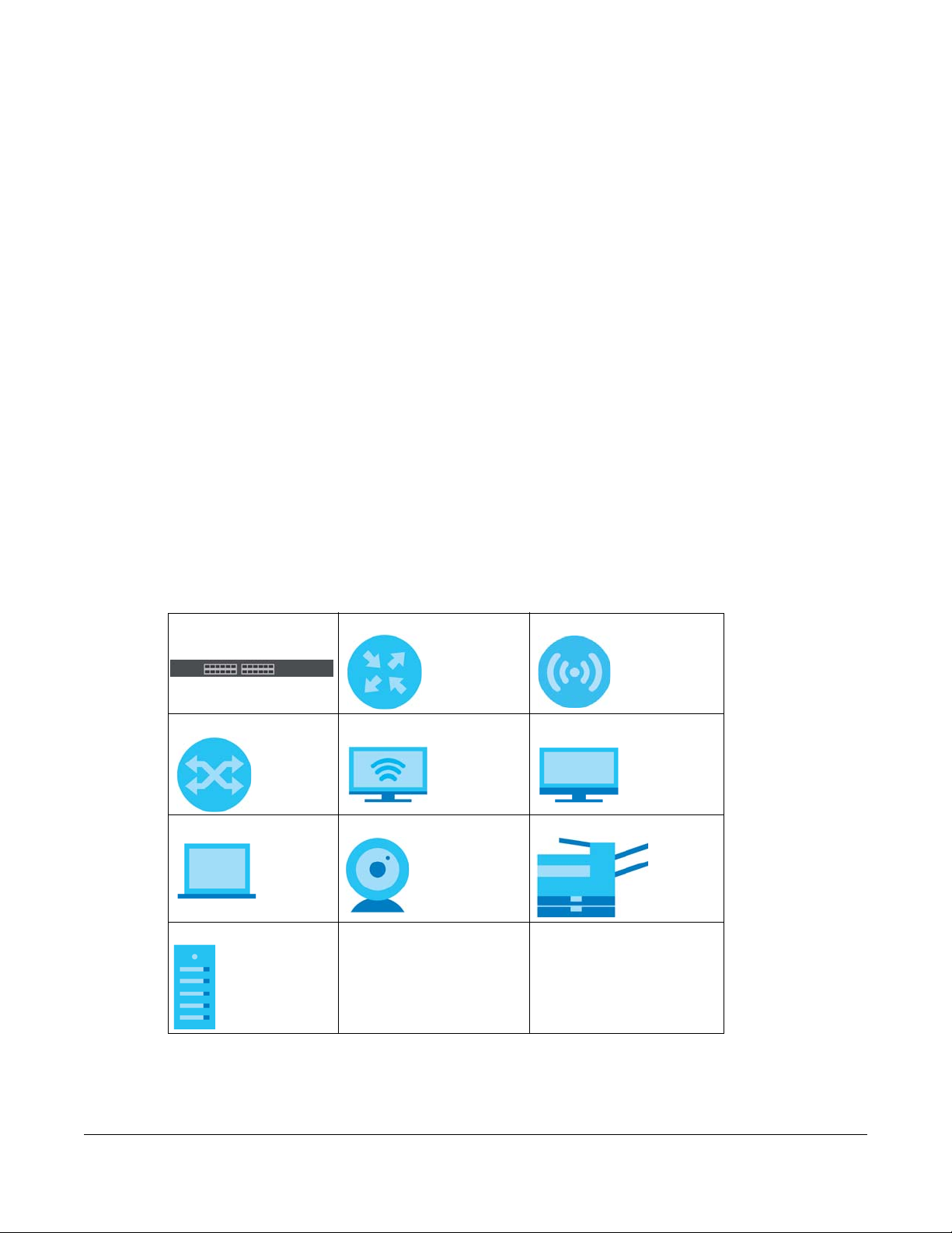
Switch Generic Router Wireless Router / Access Point
Generic Switch Smart TV Desktop
Laptop IP Camera Printer
Server
XGS2210 Series User’s Guide
3

Contents Overview
Contents Overview
User’s Guide ......................................................................................................................................23
Getting to Know Your Switch .............................................................................................................. 24
Hardware Installation and Connection ............................................................................................. 30
Hardware Panels .................................................................................................................................. 34
Technical Reference ........................................................................................................................42
Web Configurator ................................................................................................................................. 43
Initial Setup Example ............................................................................................................................ 72
Tutorials .................................................................................................................................................. 77
Status ...................................................................................................................................................... 85
Basic Setting .......................................................................................................................................... 91
VLAN .................................................................................................................................................... 135
Static MAC Forwarding ...................................................................................................................... 160
Static Multicast Forwarding ............................................................................................................... 163
Filtering ................................................................................................................................................. 166
Spanning Tree Protocol ...................................................................................................................... 168
Bandwidth Control ............................................................................................................................. 194
Broadcast Storm Control ................................................................................................................... 196
Mirroring ............................................................................................................................................... 199
Link Aggregation ................................................................................................................................ 201
Port Authentication ............................................................................................................................ 211
Port Security ......................................................................................................................................... 227
Time Range ......................................................................................................................................... 230
Classifier ............................................................................................................................................... 232
Policy Rule ........................................................................................................................................... 241
Queuing Method ................................................................................................................................ 246
Multicast .............................................................................................................................................. 250
AAA ...................................................................................................................................................... 276
IP Source Guard .................................................................................................................................. 287
DHCP Snooping .................................................................................................................................. 292
ARP Inspection .................................................................................................................................... 303
Loop Guard ......................................................................................................................................... 321
Layer 2 Protocol Tunneling ................................................................................................................ 325
sFlow ..................................................................................................................................................... 330
PPPoE ................................................................................................................................................... 334
Error-Disable ........................................................................................................................................ 343
VLAN Isolation ..................................................................................................................................... 350
MAC Pinning ....................................................................................................................................... 352
XGS2210 Series User’s Guide
4

Contents Overview
Private VLAN ....................................................................................................................................... 355
Green Ethernet ................................................................................................................................... 359
Link Layer Discovery Protocol (LLDP) ................................................................................................ 363
Anti-Arpscan ....................................................................................................................................... 391
BPDU Guard ........................................................................................................................................ 397
OAM ..................................................................................................................................................... 401
ZULD ...................................................................................................................................................... 410
Wol Relay ............................................................................................................................................. 416
Auto PD Recovery .............................................................................................................................. 418
Static Route ......................................................................................................................................... 424
Differentiated Services ....................................................................................................................... 428
DHCP .................................................................................................................................................... 432
ARP Setup ............................................................................................................................................ 448
Maintenance ...................................................................................................................................... 454
Access Control .................................................................................................................................... 470
Diagnostic ........................................................................................................................................... 495
System Log .......................................................................................................................................... 498
Syslog Setup ........................................................................................................................................ 499
Cluster Management ......................................................................................................................... 502
MAC Table ........................................................................................................................................... 508
IP Table ................................................................................................................................................. 511
ARP Table ............................................................................................................................................ 513
Routing Table ...................................................................................................................................... 515
Path MTU Table ................................................................................................................................... 517
Configure Clone ................................................................................................................................. 518
IPv6 Neighbor Table ........................................................................................................................... 522
Port Status ............................................................................................................................................ 524
Networked AV Mode ......................................................................................................................... 534
System .................................................................................................................................................. 537
Port ....................................................................................................................................................... 541
Switching ............................................................................................................................................. 548
Networking .......................................................................................................................................... 573
Security ................................................................................................................................................ 575
Maintenance ...................................................................................................................................... 587
Troubleshooting and Appendices .................................................................................................593
Troubleshooting .................................................................................................................................. 594
XGS2210 Series User’s Guide
5

Table of Contents
Table of Contents
Document Conventions .................................................................. ....................................................3
Contents Overview..............................................................................................................................4
Table of Contents.................................................................................................................................6
Part I: User’s Guide.......................................................................................... 23
Chapter 1
Getting to Know Your Switch ............................................................................................................24
1.1 Introduction ..................................................................................................................................... 24
1.1.1 ZON Utility ............................................................................................................................... 25
1.1.2 Web Configurator Networked AV Mode ........................................................................... 25
1.2 Example Applications .................................................................................................................... 26
1.2.1 Backbone Example Application ......................................................................................... 26
1.2.2 Bridging Example Application .............................................................................................27
1.2.3 High Performance Switching Example ............................................................................... 27
1.2.4 IEEE 802.1Q VLAN Application Examples ........................................................................... 28
1.3 Ways to Manage the Switch ......................................................................................................... 29
1.4 Good Habits for Managing the Switch ........................................................................................29
Chapter 2
Hardware Installation and Connection ...........................................................................................30
2.1 Safety Precautions .......................................................................................................................... 30
2.2 Freestanding Installation Procedure ............................................................................................ 30
2.3 Mounting the Switch on a Rack ................................................................................................... 31
2.3.1 Installation Requirements ..................................................................................................... 31
2.3.2 Precautions ............................................................................................................................ 31
2.3.3 Attaching the Mounting Brackets to the Switch ............................................................... 32
2.3.4 Mounting the Switch on a Rack .......................................................................................... 32
Chapter 3
Hardware Panels................................................................................................................................34
3.1 Front Panel Connections ............................................................................................................... 34
3.1.1 Gigabit Ethernet Ports ........................................................................................................... 34
3.1.2 SFP/SFP+ Slots ......................................................................................................................... 35
3.1.3 Console Port .......................................................................................................................... 37
3.2 Rear Panel ....................................................................................................................................... 37
XGS2210 Series User’s Guide
6

Table of Contents
3.2.1 Grounding .............................................................................................................................. 38
3.2.2 AC Power Connection ......................................................................................................... 40
3.3 LEDs .................................................................................................................................................. 40
Part II: Technical Reference........................................................................... 42
Chapter 4
Web Configurator...............................................................................................................................43
4.1 Overview ......................................................................................................................................... 43
4.2 System Login .................................................................................................................................... 43
4.3 Zyxel One Network (ZON) Utility .................................................................................................... 47
4.3.1 Requirements ......................................................................................................................... 47
4.3.2 Run the ZON Utility ................................................................................................................. 48
4.4 Wizard .............................................................................................................................................. 51
4.4.1 Basic Settings ......................................................................................................................... 52
4.4.2 Advanced Settings ............................................................................................................... 57
4.5 Web Configurator Layout .............................................................................................................. 62
4.5.1 Change Your Password ........................................................................................................ 69
4.6 Save Your Configuration ................................................................................................................ 69
4.7 Switch Lockout ................................................................................................................................ 69
4.8 Reset the Switch ............................................................................................................................. 70
4.8.1 Reload the Configuration File .............................................................................................. 70
4.9 Log Out of the Web Configurator ................................................................................................ 70
4.10 Help ................................................................................................................................................ 71
Chapter 5
Initial Setup Example.........................................................................................................................72
5.1 Overview ......................................................................................................................................... 72
5.1.1 Create a VLAN ...................................................................................................................... 72
5.1.2 Set Port VID ............................................................................................................................ 73
5.1.3 Configure Switch Management IP Address ....................................................................... 74
Chapter 6
Tutorials...............................................................................................................................................77
6.1 Overview ......................................................................................................................................... 77
6.2 How to Use DHCPv4 Snooping on the Switch ............................................................................. 77
6.3 How to Use DHCPv4 Relay on the Switch .................................................................................... 81
6.3.1 DHCP Relay Tutorial Introduction ........................................................................................ 81
6.3.2 Create a VLAN ...................................................................................................................... 81
6.3.3 Configure DHCPv4 Relay ..................................................................................................... 83
6.3.4 Troubleshooting ..................................................................................................................... 84
XGS2210 Series User’s Guide
7

Table of Contents
Chapter 7
Status...................................................................................................................................................85
7.1 Overview ......................................................................................................................................... 85
7.1.1 What You Can Do ................................................................................................................. 85
7.2 Status ................................................................................................................................................ 85
7.2.1 Neighbor Screen ................................................................................................................... 87
7.2.2 Neighbor Detail ..................................................................................................................... 89
Chapter 8
Basic Setting.......................................................................................................................................91
8.1 Overview ......................................................................................................................................... 91
8.1.1 What You Can Do ................................................................................................................. 91
8.2 System Information ......................................................................................................................... 91
8.2.1 System Information Stacking Hardware Monitor ............................................................... 94
8.3 General Setup ................................................................................................................................. 95
8.4 Introduction to VLANs .................................................................................................................... 97
8.5 Switch Setup .................................................................................................................................... 98
8.6 IP Setup .......................................................................................................................................... 100
8.6.1 IP Status ................................................................................................................................ 100
8.6.2 IP Status Details .................................................................................................................... 101
8.6.3 IP Configuration .................................................................................................................. 102
8.7 Port Setup ...................................................................................................................................... 104
8.8 PoE Status ...................................................................................................................................... 106
8.8.1 PoE Time Range Setup ....................................................................................................... 109
8.8.2 PoE Setup ............................................................................................................................. 111
8.9 Interface Setup ............................................................................................................................. 115
8.10 IPv6 ............................................................................................................................................... 116
8.10.1 IPv6 Status .......................................................................................................................... 116
8.10.2 IPv6 Interface Status ......................................................................................................... 116
8.10.3 IPv6 Configuration ............................................................................................................ 118
8.10.4 IPv6 Global Setup .............................................................................................................. 119
8.10.5 IPv6 Interface Setup .......................................................................................................... 120
8.10.6 IPv6 Link-Local Address Setup .......................................................................................... 121
8.10.7 IPv6 Global Address Setup ...............................................................................................121
8.10.8 IPv6 Neighbor Discovery Setup ....................................................................................... 123
8.10.9 IPv6 Router Discovery Setup ............................................................................................ 124
8.10.10 IPv6 Prefix Setup .............................................................................................................. 125
8.10.11 IPv6 Neighbor Setup ....................................................................................................... 126
8.10.12 DHCPv6 Client Setup ...................................................................................................... 128
8.11 Stacking ....................................................................................................................................... 129
8.11.1 Stacking Status .................................................................................................................. 129
8.11.2 Stacking Slot ...................................................................................................................... 130
8.11.3 Stacking Configuration .................................................................................................... 132
XGS2210 Series User’s Guide
8

Table of Contents
Chapter 9
VLAN..................................................................................................................................................135
9.1 Overview ....................................................................................................................................... 135
9.1.1 What You Can Do ............................................................................................................... 135
9.1.2 What You Need to Know ................................................................................................... 135
9.2 Introduction to IEEE 802.1Q Tagged VLANs ............................................................................... 136
9.3 VLAN Status ................................................................................................................................... 138
9.3.1 VLAN Details ........................................................................................................................ 139
9.4 Private VLAN Status ...................................................................................................................... 141
9.5 VLAN Configuration ..................................................................................................................... 141
9.6 Configure a Static VLAN .............................................................................................................. 142
9.7 Configure VLAN Port Settings ...................................................................................................... 145
9.8 Subnet Based VLANs .................................................................................................................... 147
9.8.1 Configuring Subnet Based VLAN ....................................................................................... 148
9.9 Protocol Based VLANs .................................................................................................................. 150
9.9.1 Configuring Protocol Based VLAN .................................................................................... 150
9.10 Voice VLAN ................................................................................................................................. 152
9.11 MAC Based VLAN ....................................................................................................................... 154
9.12 Vendor ID Based VLAN .............................................................................................................. 155
9.13 Port-Based VLAN Setup .............................................................................................................. 157
9.13.1 Configure a Port-Based VLAN ......................................................................................... 157
9.14 Technical Reference .................................................................................................................. 159
9.14.1 Create an IP-based VLAN Example ................................................................................ 159
Chapter 10
Static MAC Forwarding....................................................................................................................160
10.1 Overview ..................................................................................................................................... 160
10.1.1 What You Can Do ............................................................................................................. 160
10.2 Configure Static MAC Forwarding ...........................................................................................160
Chapter 11
Static Multicast Forwarding.............................................................................................................163
11.1 Overview ..................................................................................................................................... 163
11.1.1 What You Can Do ............................................................................................................. 163
11.1.2 What You Need To Know ................................................................................................. 163
11.2 Configure Static Multicast Forwarding .....................................................................................164
Chapter 12
Filtering..............................................................................................................................................166
12.1 Filtering Overview ....................................................................................................................... 166
12.1.1 What You Can Do ............................................................................................................. 166
12.2 Configure a Filtering Rule .......................................................................................................... 166
XGS2210 Series User’s Guide
9

Table of Contents
Chapter 13
Spanning Tree Protocol ...................................................................................................................168
13.1 Spanning Tree Protocol Overview ............................................................................................ 168
13.1.1 What You Can Do ............................................................................................................. 168
13.1.2 What You Need to Know ................................................................................................. 168
13.2 Spanning Tree Protocol Status .................................................................................................. 171
13.3 Spanning Tree Configuration .................................................................................................... 171
13.4 Rapid Spanning Tree Protocol Status .......................................................................................172
13.5 Configure Rapid Spanning Tree Protocol ................................................................................ 174
13.6 Configure Multiple Spanning Tree Protocol ............................................................................ 176
13.6.1 Multiple Spanning Tree Protocol Port Configuration ..................................................... 180
13.7 Multiple Spanning Tree Protocol Status ....................................................................................182
13.8 Multiple Rapid Spanning Tree Protocol .................................................................................... 186
13.9 Multiple Rapid Spanning Tree Protocol Status ........................................................................ 188
13.10 Technical Reference ................................................................................................................ 191
13.10.1 MSTP Network Example .................................................................................................. 191
13.10.2 MST Region ....................................................................................................................... 191
13.10.3 MST Instance .................................................................................................................... 192
13.10.4 Common and Internal Spanning Tree (CIST) ............................................................... 192
Chapter 14
Bandwidth Control...........................................................................................................................194
14.1 Bandwidth Control Overview .................................................................................................... 194
14.1.1 What You Can Do ............................................................................................................. 194
14.2 Bandwidth Control Setup .......................................................................................................... 194
Chapter 15
Broadcast Storm Control .................................................................................................................196
15.1 Broadcast Storm Control Overview ..........................................................................................196
15.1.1 What You Can Do ............................................................................................................. 196
15.2 Broadcast Storm Control Setup ................................................................................................ 196
Chapter 16
Mirroring............................................................................................................................................199
16.1 Mirroring Overview ..................................................................................................................... 199
16.2 Port Mirroring Setup .................................................................................................................... 199
Chapter 17
Link Aggregation .................................... .... .... ... ............................................ .... ..............................201
17.1 Link Aggregation Overview ....................................................................................................... 201
17.1.1 What You Can Do ............................................................................................................. 201
17.1.2 What You Need to Know ................................................................................................. 201
17.2 Link Aggregation Status ............................................................................................................. 202
XGS2210 Series User’s Guide
10

Table of Contents
17.3 Link Aggregation Setting ........................................................................................................... 203
17.3.1 Link Aggregation Control Protocol ................................................................................. 206
17.4 Technical Reference .................................................................................................................. 209
17.4.1 Static Trunking Example ................................................................................................... 209
Chapter 18
Port Authentication..........................................................................................................................211
18.1 Port Authentication Overview .................................................................................................. 211
18.1.1 What You Can Do ............................................................................................................. 211
18.1.2 What You Need to Know ................................................................................................. 212
18.1.3 MAC Authentication ........................................................................................................ 212
18.2 Port Authentication Configuration ........................................................................................... 213
18.3 Activate IEEE 802.1x Security ..................................................................................................... 213
18.4 Activate MAC Authentication .................................................................................................. 216
18.5 Guest VLAN ................................................................................................................................. 218
18.6 Compound Authentication ....................................................................................................... 221
18.7 Technical Reference .................................................................................................................. 224
18.7.1 IEEE 802.1x .......................................................................................................................... 224
18.7.2 RADIUS ................................................................................................................................ 224
18.7.3 EAP (Extensible Authentication Protocol) Authentication ........................................... 225
18.7.4 EAPOL (EAP over LAN) ...................................................................................................... 226
Chapter 19
Port Security......................................................................................................................................227
19.1 About Port Security ..................................................................................................................... 227
19.2 Port Security Setup ...................................................................................................................... 227
Chapter 20
Time Range.......................................................................................................................................230
20.1 Time Range Overview ................................................................................................................ 230
20.1.1 What You Can Do ............................................................................................................. 230
20.2 Configuring Time Range ............................................................................................................ 230
Chapter 21
Classifier............................................................................................................................................232
21.1 Classifier Overview ..................................................................................................................... 232
21.1.1 What You Can Do ............................................................................................................. 232
21.1.2 What You Need to Know ................................................................................................. 232
21.2 Classifier Status ............................................................................................................................ 233
21.3 Classifier Configuration .............................................................................................................. 233
21.3.1 Viewing and Editing Classifier Configuration Summary ............................................... 237
21.4 Classifier Global Setting Configuration .................................................................................... 239
21.5 Classifier Example ....................................................................................................................... 239
XGS2210 Series User’s Guide
11

Table of Contents
Chapter 22
Policy Rule ........................................................................................................................................241
22.1 Policy Rules Overview ................................................................................................................ 241
22.1.1 What You Can Do ............................................................................................................. 241
22.1.2 DiffServ ................................................................................................................................ 241
22.1.3 DSCP and Per-Hop Behavior ........................................................................................... 241
22.2 Configuring Policy Rules ............................................................................................................ 242
22.3 Policy Example ............................................................................................................................ 244
Chapter 23
Queuing Method..............................................................................................................................246
23.1 Queuing Method Overview ...................................................................................................... 246
23.1.1 What You Can Do ............................................................................................................. 246
23.1.2 What You Need to Know ................................................................................................. 246
23.2 Configuring Queuing ................................................................................................................. 247
Chapter 24
Multicast............................................................................................................................................250
24.1 Multicast Overview ..................................................................................................................... 250
24.1.1 What You Can Do ............................................................................................................. 250
24.1.2 What You Need to Know ................................................................................................. 250
24.2 Multicast Setup ........................................................................................................................... 254
24.3 IPv4 Multicast Status ................................................................................................................... 254
24.3.1 IGMP Snooping .................................................................................................................. 255
24.3.2 IGMP Snooping VLAN ....................................................................................................... 259
24.3.3 IGMP Filtering Profile ......................................................................................................... 260
24.4 IPv6 Multicast Status ................................................................................................................... 261
24.4.1 MLD Snooping-proxy ........................................................................................................ 261
24.4.2 MLD Snooping-proxy VLAN .............................................................................................. 262
24.4.3 MLD Snooping-proxy VLAN Port Role Setting ................................................................. 264
24.4.4 MLD Snooping-proxy Filtering .......................................................................................... 266
24.4.5 MLD Snooping-proxy Filtering Profile ............................................................................... 268
24.5 General MVR Configuration ...................................................................................................... 269
24.5.1 MVR Group Configuration ............................................................................................... 272
24.5.2 MVR Configuration Example ........................................................................................... 274
Chapter 25
AAA...................................................................................................................................................276
25.1 Authentication, Authorization and Accounting (AAA) ......................................................... 276
25.1.1 What You Can Do ............................................................................................................. 276
25.1.2 What You Need to Know ................................................................................................. 276
25.2 AAA Screens ............................................................................................................................... 277
25.3 RADIUS Server Setup ................................................................................................................... 277
XGS2210 Series User’s Guide
12

Table of Contents
25.4 TACACS+ Server Setup ............................................................................................................... 279
25.5 AAA Setup ................................................................................................................................... 281
25.6 Technical Reference .................................................................................................................. 283
25.6.1 Vendor Specific Attribute ................................................................................................ 283
25.6.2 Supported RADIUS Attributes ........................................................................................... 285
25.6.3 Attributes Used for Authentication .................................................................................. 285
Chapter 26
IP Source Guard...............................................................................................................................287
26.1 IP Source Guard Overview ........................................................................................................ 287
26.1.1 What You Can Do ............................................................................................................. 287
26.1.2 What You Need to Know ................................................................................................. 287
26.2 IP Source Guard .......................................................................................................................... 288
26.3 IPv4 Source Guard Setup ........................................................................................................... 288
26.4 IPv4 Source Guard Static Binding ............................................................................................. 289
Chapter 27
DHCP Snooping................................................................................................................................292
27.1 DHCP Snooping Overview ......................................................................................................... 292
27.1.1 What You Can Do ............................................................................................................. 292
27.2 DHCP Snooping .......................................................................................................................... 292
27.3 DHCP Snooping Configure ........................................................................................................ 295
27.3.1 DHCP Snooping Port Configure ...................................................................................... 297
27.3.2 DHCP Snooping VLAN Configure .................................................................................... 299
27.3.3 DHCP Snooping VLAN Port Configure ............................................................................ 300
27.4 Technical Reference .................................................................................................................. 301
27.4.1 DHCP Snooping Overview ............................................................................................... 301
Chapter 28
ARP Inspection .................................................................................................................................303
28.1 ARP Inspection Status ................................................................................................................. 303
28.1.1 ARP Inspection VLAN Status ............................................................................................. 304
28.1.2 ARP Inspection Log Status ................................................................................................ 304
28.2 ARP Inspection Configure .......................................................................................................... 305
28.2.1 ARP Inspection Port Configure ........................................................................................ 307
28.2.2 ARP Inspection VLAN Configure ..................................................................................... 308
28.3 IPv6 Source Guard Overview .................................................................................................... 309
28.4 IPv6 Source Binding Status ......................................................................................................... 310
28.5 IPv6 Static Binding Setup ........................................................................................................... 311
28.6 IPv6 Source Guard Policy Setup ............................................................................................... 313
28.7 IPv6 Source Guard Port Setup ................................................................................................... 314
28.8 IPv6 Snooping Policy Setup ....................................................................................................... 315
28.9 IPv6 Snooping VLAN Setup ........................................................................................................ 316
XGS2210 Series User’s Guide
13

Table of Contents
28.10 IPv6 DHCP Trust Setup .............................................................................................................. 317
28.11 Technical Reference ................................................................................................................ 319
28.11.1 ARP Inspection Overview ............................................................................................... 319
Chapter 29
Loop Guard ......................................................................................................................................321
29.1 Loop Guard Overview ............................................................................................................... 321
29.1.1 What You Can Do ............................................................................................................. 321
29.1.2 What You Need to Know ................................................................................................. 321
29.2 Loop Guard Setup ...................................................................................................................... 323
Chapter 30
Layer 2 Protocol Tunneling..............................................................................................................325
30.1 Layer 2 Protocol Tunneling Overview .......................................................................................325
30.1.1 What You Can Do ............................................................................................................. 325
30.1.2 What You Need to Know ................................................................................................. 325
30.2 Configuring Layer 2 Protocol Tunneling ................................................................................... 326
Chapter 31
sFlow..................................................................................................................................................330
31.1 sFlow Overview ........................................................................................................................... 330
31.2 sFlow Port Configuration ............................................................................................................ 330
31.2.1 sFlow Collector Configuration ......................................................................................... 332
Chapter 32
PPPoE.................................................................................................................................................334
32.1 PPPoE Intermediate Agent Overview ...................................................................................... 334
32.1.1 What You Can Do ............................................................................................................. 334
32.1.2 What You Need to Know ................................................................................................. 334
32.2 PPPoE ........................................................................................................................................... 336
32.3 PPPoE Intermediate Agent ........................................................................................................ 337
32.3.1 PPPoE IA Per-Port ............................................................................................................... 338
32.3.2 PPPoE IA Per-Port Per-VLAN ............................................................................................. 340
32.3.3 PPPoE IA for VLAN ............................................................................................................. 341
Chapter 33
Error-Disable.....................................................................................................................................343
33.1 Error-Disable Overview ............................................................................................................... 343
33.1.1 CPU Protection Overview ................................................................................................ 343
33.1.2 Error-Disable Recovery Overview .................................................................................... 343
33.1.3 What You Can Do ............................................................................................................. 343
33.2 Error-Disable Settings .................................................................................................................. 344
33.3 Error-Disable Status ..................................................................................................................... 344
XGS2210 Series User’s Guide
14

Table of Contents
33.4 CPU Protection Configuration ................................................................................................... 346
33.5 Error-Disable Detect Configuration .......................................................................................... 348
33.6 Error-Disable Recovery Configuration ......................................................................................349
Chapter 34
VLAN Isolation..................................................................................................................................350
34.1 VLAN Isolation Overview ............................................................................................................ 350
34.2 Configuring VLAN Isolation ........................................................................................................ 350
Chapter 35
MAC Pinning.....................................................................................................................................352
35.1 MAC Pinning Overview .............................................................................................................. 352
35.2 MAC Pinning Configuration ...................................................................................................... 352
Chapter 36
Private VLAN........... .... ... .... ............................................ .... .... ... ........................................................355
36.1 Private VLAN Overview .............................................................................................................. 355
36.1.1 Configuration .................................................................................................................... 356
Chapter 37
Green Ethernet.................................................................. .... ...........................................................359
37.1 Green Ethernet Overview .......................................................................................................... 359
37.2 Configuring Green Ethernet ...................................................................................................... 359
Chapter 38
Link Layer Discovery Protocol (LLDP) .............................................................................................363
38.1 LLDP Overview ............................................................................................................................ 363
38.2 LLDP-MED Overview ................................................................................................................... 364
38.3 LLDP Settings ............................................................................................................................... 365
38.4 LLDP Local Status ........................................................................................................................ 366
38.4.1 LLDP Local Port Status Detail ...........................................................................................368
38.5 LLDP Remote Status .................................................................................................................... 371
38.5.1 LLDP Remote Port Status Detail ....................................................................................... 372
38.6 LLDP Configuration ..................................................................................................................... 378
38.6.1 LLDP Configuration Basic TLV Setting .............................................................................. 380
38.6.2 LLDP Configuration Org-specific TLV Setting ................................................................. 381
38.7 LLDP-MED Configuration ............................................................................................................ 383
38.8 LLDP-MED Network Policy .......................................................................................................... 384
38.9 LLDP-MED Location .................................................................................................................... 386
Chapter 39
Anti-Arpscan ....................................................................................................................................391
39.1 Anti-Arpscan Overview .............................................................................................................. 391
XGS2210 Series User’s Guide
15

Table of Contents
39.1.1 What You Can Do ............................................................................................................. 391
39.1.2 What You Need to Know ................................................................................................. 391
39.2 Anti-Arpscan Host Status ............................................................................................................ 393
39.3 Anti-Arpscan Trust Host .............................................................................................................. 393
39.4 Anti-Arpscan Configure ............................................................................................................. 394
Chapter 40
BPDU Guard......................................................................................................................................397
40.1 BPDU Guard Overview ............................................................................................................... 397
40.1.1 What You Can Do ............................................................................................................. 397
40.2 BPDU Guard Status ..................................................................................................................... 397
40.3 BPDU Guard Configuration ....................................................................................................... 398
Chapter 41
OAM..................................................................................................................................................401
41.1 OAM Overview ........................................................................................................................... 401
41.1.1 What You Can Do ............................................................................................................. 401
41.2 OAM Status .................................................................................................................................. 401
41.2.1 OAM Details ....................................................................................................................... 403
41.3 OAM Configuration .................................................................................................................... 406
41.4 OAM Remote Loopback ........................................................................................................... 408
Chapter 42
ZULD...................................................................................................................................................410
42.1 ZULD Overview ............................................................................................................................ 410
42.1.1 What You Can Do ............................................................................................................. 410
42.1.2 What You Need to Know ................................................................................................. 410
42.2 ZULD Status .................................................................................................................................. 411
42.3 ZULD Configuration .................................................................................................................... 413
Chapter 43
Wol Relay..........................................................................................................................................416
43.1 Wol Relay Overview ................................................................................................................... 416
43.2 Wol Relay ..................................................................................................................................... 416
Chapter 44
Auto PD Recovery............. .... .... ............................................ ... .... .... ................................................418
44.1 Auto PD Recovery Overview .................................................................................................... 418
44.1.1 What You Can Do ............................................................................................................. 418
44.2 Auto PD Recovery ...................................................................................................................... 418
44.2.1 Activate the Automatic PD Recovery ............................................................................ 421
Chapter 45
Static Route.......................................................................................................................................424
XGS2210 Series User’s Guide
16

Table of Contents
45.1 Static Routing Overview ............................................................................................................ 424
45.1.1 What You Can Do ............................................................................................................. 424
45.2 Static Routing .............................................................................................................................. 425
45.3 IPv4 Static Route ......................................................................................................................... 425
45.4 IPv6 Static Route ......................................................................................................................... 426
Chapter 46
Differentiated Services ....................................................................................................................428
46.1 DiffServ Overview ....................................................................................................................... 428
46.1.1 What You Can Do ............................................................................................................. 428
46.1.2 What You Need to Know ................................................................................................. 428
46.2 Activating DiffServ ...................................................................................................................... 429
46.3 DSCP-to-IEEE 802.1p Priority Settings ......................................................................................... 431
46.3.1 Configuring DSCP Settings ...............................................................................................431
Chapter 47
DHCP .................................................................................................................................................432
47.1 DHCP Overview .......................................................................................................................... 432
47.1.1 What You Can Do ............................................................................................................. 432
47.1.2 What You Need to Know ................................................................................................. 432
47.2 DHCP Configuration ................................................................................................................... 433
47.3 DHCPv4 Status ............................................................................................................................ 433
47.3.1 DHCPv4 Server Status Detail ............................................................................................ 434
47.4 DHCPv4 Relay ............................................................................................................................. 435
47.4.1 DHCPv4 Relay Agent Information ................................................................................... 435
47.4.2 DHCPv4 Option 82 Profile ................................................................................................. 436
47.4.3 Configuring DHCPv4 Global Relay ................................................................................. 437
47.4.4 Configure DHCPv4 Global Relay Port ............................................................................ 438
47.4.5 Global DHCP Relay Configuration Example .................................................................. 439
47.4.6 DHCPv4 VLAN Setting ....................................................................................................... 440
47.4.7 Configure DHCPv4 VLAN Port ......................................................................................... 442
47.4.8 Example: DHCP Relay for Two VLANs ............................................................................. 443
47.5 DHCPv6 Relay ............................................................................................................................. 444
47.6 DHCP Server Guard .................................................................................................................... 445
Chapter 48
ARP Setup..........................................................................................................................................448
48.1 ARP Overview ............................................................................................................................. 448
48.1.1 What You Can Do ............................................................................................................. 448
48.1.2 What You Need to Know ................................................................................................. 448
48.2 ARP Setup .................................................................................................................................... 450
48.2.1 ARP Learning ..................................................................................................................... 450
48.2.2 Static ARP ........................................................................................................................... 452
XGS2210 Series User’s Guide
17

Table of Contents
Chapter 49
Maintenance....................................................................................................................................454
49.1 Overview ..................................................................................................................................... 454
49.1.1 What You Can Do ............................................................................................................. 454
49.2 Maintenance Settings ................................................................................................................ 454
49.2.1 Erase Running-Configuration ........................................................................................... 456
49.2.2 Save Configuration ........................................................................................................... 456
49.2.3 Reboot System .................................................................................................................. 457
49.2.4 Stacking Default ................................................................................................................ 457
49.2.5 Factory Default .................................................................................................................. 458
49.2.6 Custom Default ................................................................................................................. 458
49.3 Firmware Upgrade ...................................................................................................................... 459
49.4 Restore Configuration ................................................................................................................ 461
49.5 Backup Configuration ................................................................................................................ 461
49.6 Auto Configuration .................................................................................................................... 462
49.7 Tech-Support ............................................................................................................................... 463
49.7.1 Tech-Support Download .................................................................................................. 465
49.8 Certificates .................................................................................................................................. 465
49.8.1 HTTPS Certificates .............................................................................................................. 467
49.9 Technical Reference .................................................................................................................. 468
49.9.1 FTP Command Line ........................................................................................................... 468
49.9.2 Filename Conventions ...................................................................................................... 468
49.9.3 FTP Command Line Procedure ........................................................................................ 468
49.9.4 GUI-based FTP Clients ....................................................................................................... 469
49.9.5 FTP Restrictions ................................................................................................................... 469
Chapter 50
Access Control.................................................................................................................................470
50.1 Access Control Overview .......................................................................................................... 470
50.1.1 What You Can Do ............................................................................................................. 470
50.2 Access Control Main Settings .................................................................................................... 470
50.3 Configure SNMP .......................................................................................................................... 471
50.3.1 Configure SNMP Trap Group ........................................................................................... 472
50.3.2 Enable or Disable Sending of SNMP Traps on a Port ..................................................... 473
50.3.3 Configure SNMP User ........................................................................................................ 475
50.4 Set Up Login Accounts ............................................................................................................... 477
50.5 Service Access Control .............................................................................................................. 478
50.6 Remote Management ............................................................................................................... 479
50.7 Technical Reference .................................................................................................................. 480
50.7.1 About SNMP ....................................................................................................................... 481
50.7.2 SSH Overview ..................................................................................................................... 487
50.7.3 Introduction to HTTPS ........................................................................................................ 489
50.7.4 Google Chrome Warning Messages .............................................................................. 493
XGS2210 Series User’s Guide
18

Table of Contents
Chapter 51
Diagnostic.........................................................................................................................................495
51.1 Overview ..................................................................................................................................... 495
51.2 Diagnostic ................................................................................................................................... 495
Chapter 52
System Log........................................................................................................................................498
52.1 Overview ..................................................................................................................................... 498
52.2 System Log .................................................................................................................................. 498
Chapter 53
Syslog Setup .....................................................................................................................................499
53.1 Syslog Overview .......................................................................................................................... 499
53.1.1 What You Can Do ............................................................................................................. 499
53.2 Syslog Setup ................................................................................................................................ 499
Chapter 54
Cluster Management.......................................................................................................................502
54.1 Cluster Management Overview ...............................................................................................502
54.1.1 What You Can Do ............................................................................................................. 502
54.2 Cluster Management Status ..................................................................................................... 503
54.3 Clustering Management Configuration .................................................................................. 504
54.4 Technical Reference .................................................................................................................. 505
54.4.1 Cluster Member Switch Management ........................................................................... 505
Chapter 55
MAC Table........................................................................................................................................508
55.1 MAC Table Overview ................................................................................................................. 508
55.1.1 What You Can Do ............................................................................................................. 508
55.1.2 What You Need to Know ................................................................................................. 508
55.2 Viewing the MAC Table ............................................................................................................. 509
Chapter 56
IP Table..............................................................................................................................................511
56.1 IP Table Overview ....................................................................................................................... 511
56.2 Viewing the IP Table ................................................................................................................... 512
Chapter 57
ARP Table..........................................................................................................................................513
57.1 Overview ..................................................................................................................................... 513
57.1.1 What You Can Do ............................................................................................................. 513
57.1.2 What You Need to Know ................................................................................................. 513
57.2 Viewing the ARP Table ............................................................................................................... 513
XGS2210 Series User’s Guide
19

Table of Contents
Chapter 58
Routing Table....................................................................................................................................515
58.1 Routing Table Overview ............................................................................................................ 515
58.2 The Routing Table Main Screen ................................................................................................ 515
58.3 IPv4 Routing Table ...................................................................................................................... 515
58.4 IPv6 Routing Table ...................................................................................................................... 516
Chapter 59
Path MTU Table.................................................................................................................................517
59.1 Path MTU Overview .................................................................................................................... 517
59.2 Viewing the Path MTU Table ..................................................................................................... 517
Chapter 60
Configure Clone.................... .... ... ............................................ .... .... ... .............................................518
60.1 Overview ..................................................................................................................................... 518
60.2 Configure Clone ......................................................................................................................... 518
Chapter 61
IPv6 Neighbor Table.........................................................................................................................522
61.1 IPv6 Neighbor Table Overview .................................................................................................. 522
61.2 Viewing the IPv6 Neighbor Table ............................................................................................. 522
Chapter 62
Port Status .........................................................................................................................................524
62.1 Overview ..................................................................................................................................... 524
62.2 Status ............................................................................................................................................ 524
62.3 Port Status .................................................................................................................................... 524
62.3.1 Port Details ......................................................................................................................... 526
62.3.2 DDMI ................................................................................................................................... 529
62.3.3 DDMI Details ...................................................................................................................... 530
62.3.4 Port Utilization .................................................................................................................... 532
Chapter 63
Networked AV Mode.......................................................................................................................534
63.1 Overview ..................................................................................................................................... 534
63.2 Summary ...................................................................................................................................... 534
Chapter 64
System...............................................................................................................................................537
64.1 What You Can Do ...................................................................................................................... 537
64.2 System Information ..................................................................................................................... 537
64.3 General Setup ............................................................................................................................. 538
XGS2210 Series User’s Guide
20

Table of Contents
Chapter 65
Port ....................................................................................................................................................541
65.1 What You Can Do ...................................................................................................................... 541
65.2 PoE Status .................................................................................................................................... 541
65.3 PoE Setup ..................................................................................................................................... 543
65.4 Port Setup .................................................................................................................................... 545
Chapter 66
Switching...........................................................................................................................................548
66.1 Broadcast Storm Control ........................................................................................................... 548
66.2 Link Aggregation ........................................................................................................................ 549
66.2.1 What You Can Do ............................................................................................................. 549
66.3 Link Aggregation Status ............................................................................................................. 550
66.4 Link Aggregation Setting ........................................................................................................... 551
66.5 Link Aggregation Control Protocol ........................................................................................... 553
66.6 VLAN ............................................................................................................................................ 555
66.6.1 What You Can Do ............................................................................................................. 555
66.6.2 What You Need to Know ................................................................................................. 555
66.7 VLAN Status ................................................................................................................................. 558
66.7.1 VLAN Detail ........................................................................................................................ 559
66.8 Static VLAN .................................................................................................................................. 560
66.9 VLAN Port Setting ........................................................................................................................ 562
66.10 Multicast .................................................................................................................................... 564
66.10.1 What You Can Do ........................................................................................................... 564
66.11 IPv4 Multicast Status ................................................................................................................. 564
66.12 IGMP Snooping ......................................................................................................................... 565
66.13 IGMP Snooping VLAN .............................................................................................................. 569
66.14 IGMP Filtering Profile ................................................................................................................. 570
Chapter 67
Networking .......................................................................................................................................573
67.1 IP Setup ........................................................................................................................................ 573
Chapter 68
Security .............................................................................................................................................575
68.1 Access Control ............................................................................................................................ 575
68.1.1 What You Can Do ............................................................................................................. 575
68.2 Set Up Login Accounts ............................................................................................................... 575
68.3 Remote Management ............................................................................................................... 577
68.4 Configure SNMP .......................................................................................................................... 579
68.5 Configure SNMP Trap Group ..................................................................................................... 581
68.6 Enable or Disable Sending of SNMP Traps on a Port .............................................................. 582
68.7 Configure SNMP User ................................................................................................................. 584
XGS2210 Series User’s Guide
21

Table of Contents
68.8 Service Access Control .............................................................................................................. 586
Chapter 69
Maintenance....................................................................................................................................587
69.1 What You Can Do ...................................................................................................................... 587
69.2 Backup Configuration ................................................................................................................ 587
69.3 Firmware Upgrade ...................................................................................................................... 588
69.4 Reboot System ............................................................................................................................ 589
69.5 Restore Configuration ................................................................................................................ 590
69.6 Save Configuration .................................................................................................................... 590
69.7 Tech-Support ............................................................................................................................... 591
69.8 Port Mirroring ............................................................................................................................... 591
Part III: Troubleshooting and Appendices..................................................593
Chapter 70
Troubleshooting................................................................................................................................594
70.1 Power, Hardware Connections, and LEDs ............................................................................... 594
70.2 Switch Access and Login ........................................................................................................... 595
70.3 Switch Configuration .................................................................................................................. 596
Appendix A Customer Support ..................................................................................................... 598
Appendix B Common Services...................................................................................................... 604
Appendix C IPv6.............................................................................................................................. 607
Appendix D Legal Information ...................................................................................................... 616
Index.................................................................................................................................................621
XGS2210 Series User’s Guide
22

PART I
User’s Guide
23
CHAPTER 1
Getting to Know Your Switch
1.1 Introduction
This chapter introduces the main features and applications of the Switch.
The XGS2210 Series consists of the following models:
• XGS2210-28
• XGS2210-28HP
• XGS2210-52
• XGS2210-52HP
References to PoE models in this User's Guide only applies to XGS2210-28HP and XGS2210-52HP.
The Switch is a stackable, layer-2, Gigabit Ethernet (GbE) switch with one power slot for single power
supply. The Switch provides four SFP+ slots for uplink. By integrating router functions, the Switch performs
wire-speed layer-3 routing in addition to layer-2 switching.
With its built-in Web Configurator, including the Zyxel One Network (ZON) Neighbor Management
feature, viewing, managing and configuring the Switch and its neighboring devices is easy. The Switch
can also be managed through Telnet, any terminal emulator program on the console port, or third-party
SNMP management.
In addition, Zyxel offers a proprietary software program called Zyxel One Network (ZON) Utility, it is a
utility tool that assists you to set up and maintain network devices in a more simple and efficient way.
You can download the ZON Utility at www.zyxel.com and install it on a PC.
All models are referred to as the “Switch” in this guide.
The following table describes the port features of the Switch by model.
Table 1 Models and Port Features
SWITCH MODEL PORT FEATURES
XGS2210-28 and XGS2210-28HP • 24 100/1000 Mbps Ethernet ports
•4 SFP+ interfaces
XGS2210-52 and XGS2210-52HP • 48 100/1000 Mbps Ethernet ports
•4 SFP+ interfaces
The XGS2210-28HP and XGS2210-52HP come with a Power-over-Ethernet (PoE) feature. The XGS221028HP and XGS2210-52HP support the IEEE 802.3at High Power over Ethernet (PoE) standard and IEEE
802.3af PoE standard.
XGS2210 Series User’s Guide
24

The following table describes the PoE features of the Switch by model.
Table 2 Models and PoE Features
SWITCH MODEL POE FEATURES
XGS2210-28HP
XGS2210-52HP
This section shows a few examples of using the Switch in various network environments.
1.1.1 ZON Utility
With its built-in Web Configurator, including the Neighbor Management feature (Section 7.2.1 on page
87), viewing, managing and configuring the Switch and its neighboring devices is simplified.
Chapter 1 Getting to Know Your Switch
IEEE 802.3af PoE
IEEE 802.3 at High Power over Ethernet (PoE)
Power management mode – Classification
Power management mode – Consumption
Total PoE budget – 375 watts (see Section 8.8 on page 106 for details)
For example, if an IP camera requires 25 watts power on average, then the Switch
can supply PoE to up to 15 IP cameras.
In addition, Zyxel offers a proprietary software program called Zyxel One Network (ZON) Utility, it is a
utility tool that assists you to set up and maintain network devices in a more simple and efficient way.
You can download the ZON Utility at www.zyxel.com and install it on a PC (Windows operation system).
For more information on ZON Utility see Section 4.3 on page 47.
1.1.2 Web Configurator Networked AV Mode
Aside from the Web Configurator in Standard mode, you can switch to Networked AV mode that is
specifically designed to simplify configuration and management of the Switch for AVoIP (Audio-Video
over Internet Protocol) application. In AV over IP, the AV transmitter is the transmitter, the AV receiver is
the receiver, and the matrix switch is a standard IP Switch. See Section 4.4 on page 51 for details on
using the Setup Wizard screen for configuring the Switch’s Networked AV mode’s basic and advanced
settings.
XGS2210 Series User’s Guide
25
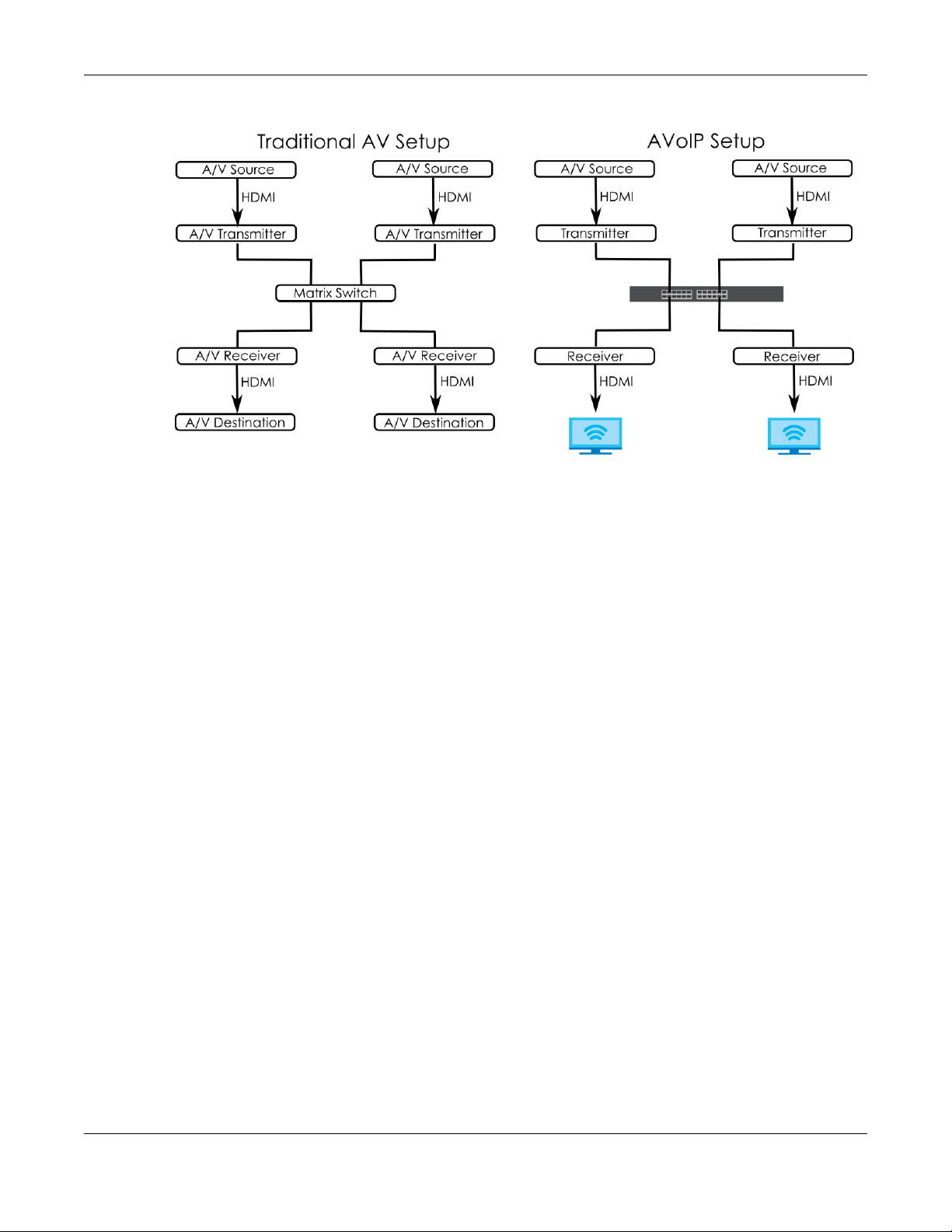
Chapter 1 Getting to Know Your Switch
Figure 1 Comparison Between Traditional AV and AVoIP Setups
1.2 Example Applications
This section shows a few examples of using the Switch in various network environments. Note that the
Switch in the figure is just an example Switch and not your actual Switch.
1.2.1 Backbone Example Application
The Switch is an ideal solution for small networks where rapid growth can be expected in the near future.
The Switch can be used standalone for a group of heavy traffic users. You can connect computers and
servers directly to the Switch’s port or connect other switches to the Switch.
In this example, all computers can share high-speed applications on the server. To expand the network,
simply add more networking devices such as switches, routers, computers, print servers, and so on.
XGS2210 Series User’s Guide
26
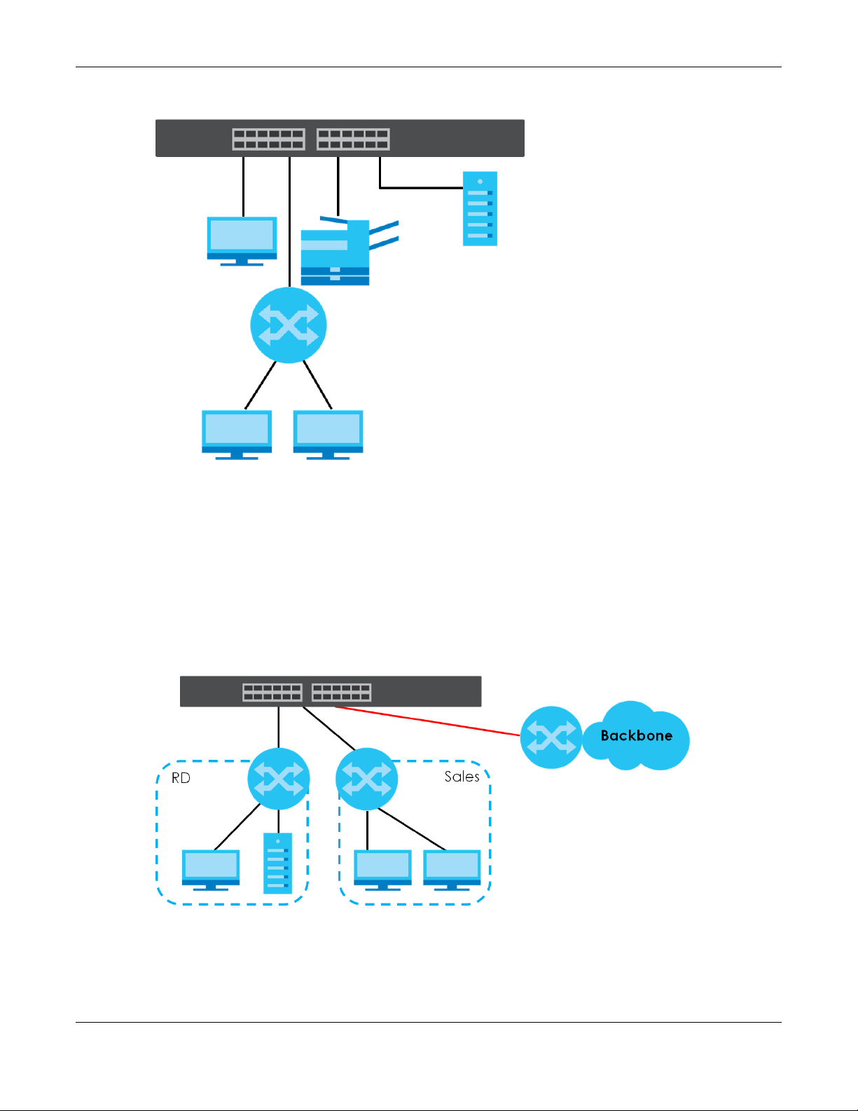
Chapter 1 Getting to Know Your Switch
Figure 2 Backbone Application
1.2.2 Bridging Example Application
In this example, the Switch connects different company departments (RD and Sales) to the corporate
backbone. It can alleviate bandwidth contention and eliminate server and network bottlenecks. All
users that need high bandwidth can connect to high-speed department servers through the Switch.
You can provide a super-fast uplink connection by using a Gigabit Ethernet or SFP port on the Switch.
Moreover, the Switch eases supervision and maintenance by allowing network managers to centralize
multiple servers at a single location.
Figure 3 Bridging Application
1.2.3 High Performance Switching Example
The Switch is ideal for connecting two networks that need high bandwidth. In the following example, use
link aggregation (trunking) to connect these two networks.
XGS2210 Series User’s Guide
27
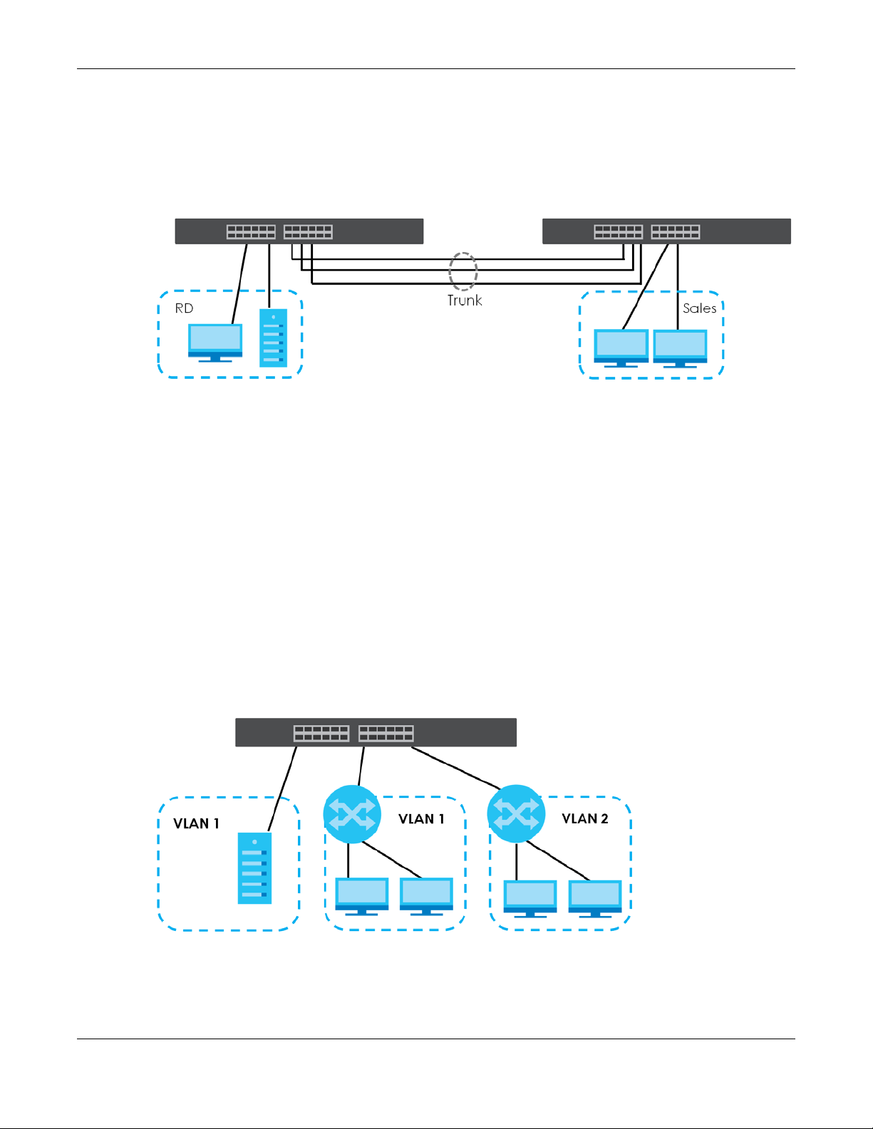
Chapter 1 Getting to Know Your Switch
Switching to higher-speed LANs such as ATM (Asynchronous Transmission Mode) is not feasible for most
people due to the expense of replacing all existing Ethernet cables and adapter cards, restructuring
your network and complex maintenance. The Switch can provide the same bandwidth as ATM at much
lower cost while still being able to use existing adapters and switches. Moreover, the current LAN
structure can be retained as all ports can freely communicate with each other.
Figure 4 High Performance Switched Workgroup Application
1.2.4 IEEE 802.1Q VLAN Application Examples
A VLAN (Virtual Local Area Network) allows a physical network to be partitioned into multiple logical
networks. Stations on a logical network belong to one or more groups. With VLAN, a station cannot
directly talk to or hear from stations that are not in the same groups unless such traffic first goes through
a router.
1.2.4.1 Tag-based VLAN Example
Ports in the same VLAN group share the same frame broadcast domain thus increase network
performance through reduced broadcast traffic. VLAN groups can be modified at any time by adding,
moving or changing ports without any re-cabling.
Shared resources such as a server can be used by all ports in the same VLAN as the server. In the
following figure only ports that need access to the server need to be part of VLAN 1. Ports can belong to
other VLAN groups too.
Figure 5 Shared Server Using VLAN Example
XGS2210 Series User’s Guide
28

Chapter 1 Getting to Know Your Switch
1.3 Ways to Manage the Switch
Use any of the following methods to manage the Switch.
• Web Configurator. This is recommended for everyday management of the Switch using a (supported)
web browser. See Chapter 4 on page 43.
• Command Line Interface. Line commands offer an alternative to the Web Configurator and in some
cases are necessary to configure advanced features. See the CLI Reference Guide.
• FTP. Use File Transfer Protocol for firmware upgrades and configuration backup or restore. See Section
49.9.1 on page 468.
• SNMP. The Switch can be monitored and/or managed by an SNMP manager. See Section 50.7.1 on
page 481.
• Cluster Management. Cluster Management allows you to manage multiple switches through one
switch, called the cluster manager. See Chapter 54 on page 502.
• ZON Utility. ZON Utility is a program designed to help you deploy and perform initial setup on a
network more efficiently. See Section 4.3 on page 47.
1.4 Good Habits for Managing the Switch
Do the following regularly to make the Switch more secure and to manage the Switch more effectively.
• Change the password. Use a password that is not easy to guess and that consists of different types of
characters, such as numbers and letters.
• Write down the password and put it in a safe place.
• Back up the configuration (and make sure you know how to restore it). Restoring an earlier working
configuration may be useful if the device becomes unstable or even crashes. If you forget your
password, you will have to reset the Switch to its factory default settings. If you backed up an earlier
configuration file, you would not have to totally re-configure the Switch. You could simply restore your
last configuration.
XGS2210 Series User’s Guide
29

Hardware Installation and
This chapter shows you how to install and connect the Switch.
The Switch can be:
• Placed on a desktop.
• Rack-mounted on a standard EIA rack.
2.1 Safety Precautions
CHAPTER 2
Connection
Please observe the following before using the Switch:
• It is recommended to ask an authorized technician to attach the Switch on a desk or to the rack or
wall. Use the proper screws to prevent damage to the Switch. See the Installation Requirements
sections in this chapter to know the types of screws and screwdrivers for each mounting method.
• Make sure there is at least 2 cm of clearance on the top and bottom of the Switch, and at least 5 cm
of clearance on all four sides of the Switch. This allows air circulation for cooling.
• Do NOT block the ventilation holes nor store cables or power cords on the Switch. Allow clearance for
the ventilation holes to prevent your Switch from overheating. This is especially crucial when your
Switch does not have fans. Overheating could affect the performance of your Switch, or even
damage it.
• The surface of the Switch could be hot when it is functioning. Do NOT put your hands on it. You may
get burned. This could happen especially when you are using a fanless Switch.
• The Switches with fans are not suitable for use in locations where children are likely to be present.
To start using the Switch, simply connect the power cables and turn it on.
2.2 Freestanding Installation Procedure
1 Make sure the Switch is clean and dry.
2 Remove the adhesive backing from the rubber feet.
3 Attach the rubber feet to each corner on the bottom of the Switch. These rubber feet help protect the
Switch from shock or vibration and ensure space between devices when stacking.
XGS2210 Series User’s Guide
30

Chapter 2 Hardware Installation and Connection
Figure 6 Attaching Rubber Feet
4 Set the Switch on a smooth, level surface strong enough to support the weight of the Switch and the
connected cables. Make sure there is a power outlet nearby.
Cautions:
• Avoid stacking fanless Switches to prevent overheating.
• Ensure enough clearance around the Switch to allow air circulation for cooling.
• Do NOT remove the rubber feet as it provides space for air circulation.
2.3 Mounting the Switch on a Rack
The Switch can be mounted on an EIA standard size, 19-inch rack or in a wiring closet with other
equipment. Follow the steps below to mount your Switch on a standard EIA rack using a rack-mounting
kit.
Note: Make sure there is enough clearance between each equipment on the rack for air
circulation.
2.3.1 Installation Requirements
• Two mounting brackets.
• Eight M3 flat head screws and a #2 Philips screwdriver.
• Four M5 flat head screws and a #2 Philips screwdriver.
2.3.2 Precautions
• Make sure the rack will safely support the combined weight of all the equipment it contains. The
maximum weight a bracket can hold is 21.5 kg.
• Make sure the position of the Switch does not make the rack unstable or top-heavy. Take all
necessary precautions to anchor the rack securely before installing the unit.
XGS2210 Series User’s Guide
31

Chapter 2 Hardware Installation and Connection
2.3.3 Attaching the Mounting Brackets to the Switch
1 Position a mounting bracket on one side of the Switch, lining up the four screw holes on the bracket with
the screw holes on the side of the Switch.
Figure 7 Attaching the Mounting Brackets
2 Using a #2 Philips screwdriver, install the M3 flat head screws through the mounting bracket holes into
the Switch.
3 Repeat steps 1 and 2 to install the second mounting bracket on the other side of the Switch.
4 You may now mount the Switch on a rack. Proceed to the next section.
2.3.4 Mounting the Switch on a Rack
1 Position a mounting bracket (that is already attached to the Switch) on one side of the rack, lining up
the two screw holes on the bracket with the screw holes on the side of the rack.
Figure 8 Mounting the Switch on a Rack
XGS2210 Series User’s Guide
32

Chapter 2 Hardware Installation and Connection
2 Using a #2 Philips screwdriver, install the M5 flat head screws through the mounting bracket holes into
the rack.
Note: Make sure you tighten all the four screws to prevent the Switch from getting slanted.
3 Repeat steps 1 and 2 to attach the second mounting bracket on the other side of the rack.
XGS2210 Series User’s Guide
33

Chapter 3 Hardware Panels
Hardware Panels
This chapter describes the front panel and rear panel of the Switch and shows you how to make the
hardware connections.
3.1 Front Panel Connections
Figure 9 Front Panel: XGS2210-28
CHAPTER 3
Figure 10 Front Panel: XGS2210-28HP
Figure 11 Front Panel: XGS2210-52
Figure 12 Front Panel: XGS2210-52HP
3.1.1 Gigabit Ethernet Ports
The Switch has 1000Base-T auto-negotiating, auto-crossover Ethernet ports. In 10/100/1000 Mbps Gigabit
Ethernet, the speed can be 10 Mbps, 100 Mbps or 1000 Mbps. The duplex mode can be half duplex or
full duplex.
An auto-negotiating port can detect and adjust to the optimum Ethernet speed (10/100/1000 Mbps)
and duplex mode (full duplex or half duplex) of the connected device.
An auto-crossover (auto-MDI/MDI-X) port automatically works with a straight-through or crossover
Ethernet cable.
When auto-negotiation is turned on, an Ethernet port negotiates with the peer automatically to
determine the connection speed and duplex mode. If the peer Ethernet port does not support auto-
XGS2210 Series User’s Guide
34

Chapter 3 Hardware Panels
negotiation or turns off this feature, the Switch determines the connection speed by detecting the signal
on the cable and using half duplex mode. When the Switch’s auto-negotiation is turned off, an Ethernet
port uses the pre-configured speed and duplex mode when making a connection, thus requiring you to
make sure that the settings of the peer Ethernet port are the same in order to connect.
3.1.1.1 Default Ethernet Negotiation Settings
The factory default negotiation settings for the Gigabit ports on the Switch are:
• Speed: Auto
•Duplex: Auto
• Flow control: Off
• Link Aggregation: Disabled
3.1.1.2 Auto-crossover
All ports support auto-crossover, that is auto-MDIX ports (Media Dependent Interface Crossover), so you
may use either a straight-through Ethernet cable or crossover Ethernet cable for all Gigabit port
connections. Auto-crossover ports automatically sense whether they need to function as crossover or
straight ports, so crossover cables can connect both computers and switches or hubs.
3.1.2 SFP/SFP+ Slots
These are four slots for Small Form-Factor Pluggable (SFP) or SFP+ modules, such as an SFP or SFP+
transceiver. The SFP+ (SFP Plus) is an enhanced version of the SFP and supports data rates of 10 Gbps. A
transceiver is a single unit that houses a transmitter and a receiver. Use a transceiver to connect a fiber
cable to the Switch. The Switch does not come with transceivers. You must use transceivers that comply
with the Small Form-Factor Pluggable (SFP) Transceiver MultiSource Agreement (MSA). See the SFF
committee’s INF-8074i specification Rev 1.0 for details.
You can change transceivers while the Switch is operating. You can use different transceivers to
connect to Ethernet switches with different types of fiber connectors.
• Type: SFP or SFP+ connection interface
• Connection speed: 1 or 10 Gigabit per second (Gbps)
WARNING! To avoid possible eye injury, do not look into an operating
fiber module’s connectors.
HANDLING! All transceivers are static sensitive. To prevent damage from
electrostatic discharge (ESD), it is recommended you attach an ESD
preventive wrist strap to your wrist and to a bare metal surface when
you install or remove a transceiver.
STORAGE! All modules are dust sensitive. When not in use, always keep
the dust plug on. Avoid getting dust and other contaminant into the
optical bores, as the optics do not work correctly when obstructed with
dust.
3.1.2.1 Transceiver Installation
Use the following steps to install a transceiver.
XGS2210 Series User’s Guide
35

1 Attach an ESD preventive wrist strap to your wrist and to a bare metal surface.
2 Align the transceiver in front of the slot opening.
3 Make sure the latch is in the lock position (latch styles vary), then insert the transceiver into the slot with
the exposed section of PCB board facing down.
4 Press the transceiver firmly until it clicks into place.
5 The Switch automatically detects the installed transceiver. Check the LEDs to verify that it is functioning
properly.
6 Remove the dust plugs from the transceiver and cables (dust plug styles vary).
7 Identify the signal transmission direction of the fiber cables and the transceiver. Insert the fiber cable into
the transceiver.
Figure 13 Latch in the Lock Position
Figure 14 Transceiver Installation Example
Figure 15 Connecting the Fiber Cables
3.1.2.2 Transceiver Removal
Use the following steps to remove an SFP transceiver.
1 Attach an ESD preventive wrist strap to your wrist and to a bare metal surface on the chassis.
2 Remove the fiber cables from the transceiver.
3 Pull out the latch and down to unlock the transceiver (latch styles vary).
Note: Make sure the transceiver’s latch is pushed all the way down, so the transceiver can be
pulled out successfully.
4 Pull the latch, or use your thumb and index finger to grasp the tabs on both sides of the transceiver, and
carefully slide it out of the slot.
XGS2210 Series User’s Guide
36

Chapter 3 Hardware Panels
Note: Do NOT pull the transceiver out by force. You could damage it. If the transceiver will not
slide out, grasp the tabs on both sides of the transceiver with a slight up or down motion
and carefully slide it out of the slot. If unsuccessful, contact Zyxel Support to prevent
damage to your Switch and transceiver.
5 Insert the dust plug into the ports on the transceiver and the cables.
Figure 16 Removing the Fiber Cables
Figure 17 Opening the Transceiver’s Latch Example
Figure 18 Transceiver Removal Example
3.1.3 Console Port
This console port is for troubleshooting only. With instructions from customer support, connect the male 9pin end of the RS-232 console cable to the console port of the Switch. Connect the female end to a
serial port (COM1, COM2 or other COM port) of your computer. You can use a computer with terminal
emulation software configured to the following parameters:
• VT100 terminal emulation
• 115200 bps
• No parity, 8 data bits, 1 stop bit
• No flow control
3.2 Rear Panel
The following figures show the rear panels of the Switch. The rear panels contain:
Figure 19 Rear Panel: XGS2210-28
XGS2210 Series User’s Guide
37

Figure 20 Rear Panel: XGS2210-28HP
Figure 21 Rear Panel: XGS2210-52
Figure 22 Rear Panel: XGS2210-52HP
3.2.1 Grounding
Grounding is a safety measure to direct excess electric charge to the ground. It prevents damage to
the Switch, and protects you from electrocution. Use the grounding screw on the rear panel and the
ground wire of the AC power supply to ground the Switch.
Chapter 3 Hardware Panels
The grounding terminal and AC power ground where you install the Switch must follow your country’s
regulations. Qualified service personnel must ensure the building’s protective earthing terminals are
valid terminals.
Installation of Ethernet cables must be separate from AC power lines. To avoid electric surge and
electromagnetic interference, use a different electrical conduit or raceway (tube/trough or enclosed
conduit for protecting electric wiring) that is 15 cm apart, or as specified by your country’s electrical
regulations.
Any device that is located outdoors and connected to this product must be properly grounded and
surge protected. To the extent permissible by your country’s applicable law, failure to follow these
guidelines could result in damage to your Switch which may not be covered by its warranty.
Note: The specification for surge or ESD protection assumes that the Switch is properly
grounded.
1 Remove the M4 ground screw from the Switch’s rear panel.
2 Secure a green or yellow ground cable (16 AWG or smaller) to the Switch's rear panel using the M4
ground screw.
XGS2210 Series User’s Guide
38

Chapter 3 Hardware Panels
Figure 23 Grounding
3 Attach the other end of the ground cable to a grounding bar located on the rack where you install the
Switch or to an on-site grounding terminal.
Figure 24 Attach Ground Cable to Grounding Bar or On-site Grounding Terminal
4 The grounding terminal of the server rack or on-site grounding terminal must also be grounded and
connected to the building’s main grounding electrode. Make sure the grounding terminal is connected
to the buildings grounding electrode and has an earth resistance of less than 10 ohms, or according to
your country’s electrical regulations.
Figure 25 Connecting to the Building’s Main Grounding Electrode
If you are uncertain that suitable grounding is available, contact the appropriate electrical inspection
XGS2210 Series User’s Guide
39

authority or an electrician.
This device must be grounded. Do this before you make other
connections.
3.2.2 AC Power Connection
Note: Make sure you are using the correct power source as shown on the panel and that no
objects obstruct the airflow of the fans (located on the side of the unit).
To connect power to the Switch, insert the female end of the power cord to the AC power receptacle
on the rear panel. Connect the other end of the supplied power cord to a power outlet.
3.3 LEDs
After you connect the power to the Switch, view the LEDs to ensure proper functioning of the Switch
and as an aid in troubleshooting.
Chapter 3 Hardware Panels
Table 3 LED Descriptions
LED COLOR STATUS DESCRIPTION
PWR Green On The system is receiving power from the power module in the power slot. The
Blue On The Switch is acting as the master in stacking.
Off The system is not receiving power from the power module in the power slot.
SYS Green On The system is on and functioning properly.
Blinking The system is rebooting and performing self-diagnostic tests.
Red On The system is functioning abnormally.
Off The power is off or the system is not ready or malfunctioning.
FAN Green On The fan is functioning properly.
Amber On The fan is not functioning at a proper speed or malfunctioning.
LOCATOR Blue Blinking Shows the actual location of the Switch between several devices in a rack.
Off The locator is not functioning or malfunctioning.
PoE MAX Green On PoE power usage is over 80 percent of the power supplied budget, but
Amber On PoE power usage is more than 95 percent of the power supplied budget.
Off PoE power usage is below 80 percent of the power supplied budget.
10/100/1000Base-T Ports
1 – 48 LNK/ACT
(Left)
Green On The link to a 10 Mbps or a 1000 Mbps Ethernet network is up.
Blinking The system is transmitting/receiving to/from a 10 Mbps or a 1000 Mbps
Amber On The link to a 100 Mbps Ethernet network is up.
Blinking The system is transmitting/receiving to/from a 100 Mbps Ethernet network.
Off The link to an Ethernet network is down.
Switch is acting as a non-master member in a stack or it is in standalone
mode.
The default timer is 30 minutes when you are configuring the Switch.
below 95 percent of the power supplied budget.
Ethernet network.
XGS2210 Series User’s Guide
40

Chapter 3 Hardware Panels
Table 3 LED Descriptions (continued)
LED COLOR STATUS DESCRIPTION
PoE 10/100/1000Base-T Ports
1 – 48 LNK/ACT
(Left)
1 – 48 PoE
(Right)
1G/10G SFP+ Slots
49 – 52 LNK/ACT Green On The port has a successful 1000 Mbps connection.
Green On The link to a 10 Mbps or a 1000 Mbps Ethernet network is up.
Blinking The system is transmitting/receiving to/from a 10 Mbps or a 1000 Mbps
Ethernet network.
Amber On The link to a 100 Mbps Ethernet network is up.
Blinking The system is transmitting/receiving to/from a 100 Mbps Ethernet network.
Off The link to an Ethernet network is down.
Green On Power supplied to all PoE Ethernet ports meets the IEEE 802.3at standard.
Amber On Power supplied to all PoE Ethernet ports meets the IEEE 802.3af standard.
Off There is no power supplied.
Blinking The port is transmitting or receiving data at 1000 Mbps.
Blue On The port has a successful 10 Gbps connection.
Blinking The port is transmitting or receiving data at 10 Gbps.
Off This link is disconnected.
XGS2210 Series User’s Guide
41

PART II
Technical Reference
42

4.1 Overview
This section introduces the configuration and functions of the Web Configurator.
The Web Configurator is an HTML-based management interface that allows easy system setup and
management through Internet browser. Use a browser that supports HTML5, such as Microsoft Edge,
Internet Explorer 11, Mozilla Firefox, or Google Chrome. The minimum recommended screen resolution is
1024 by 768 pixels.
In order to use the Web Configurator you need to allow:
• Web browser pop-up windows from your device.
• JavaScript (enabled by default).
• Java permissions (enabled by default).
CHAPTER 4
Web Configurator
4.2 System Login
1 Start your web browser.
2 The Switch is a DHCP client by default. Type “http://DHCP-assigned IP” in the Location or Address field.
Press [ENTER].
If the Switch is not connected to a DHCP server, type “http://” and the static IP address of the Switch (for
example, the default management IP address is 192.168.1.1 through an in-band port) in the Location or
Address field. Press [ENTER]. Your computer must be in the same subnet in order to access this website
address.
Also, you can use the ZON Utility to check your Switch’s IP address. See Section 4.3 on page 47 for more
information on the ZON utility.
3 The following screen appears.
XGS2210 Series User’s Guide
43

Chapter 4 Web Configurator
Figure 26 Web Configurator: Login
4 Click Login to log into the Web Configurator to manage the Switch directly. The default user name is
admin and associated default password is 1234.
5 The following screen appears.
Figure 27 Select Mode
6 Select the Web Configurator in Standard Mode that has a complete set of configuration for network
installation. Or select the Web Configurator in Networked AV Mode that has a set of menus specifically
designed to simplify configuration and management of the Switch for AVoIP (Audio-Video over Internet
Protocol) application.
7 If you select Standard Mode, go directly to step 9.
XGS2210 Series User’s Guide
44

Chapter 4 Web Configurator
8 The Setup Wizard screen will appear after selecting the Networked AV Mode. You can use the Setup
Wizard screen to configure the Switch’s Networked AV mode’s basic or advanced settings (see Section
4.4 on page 51 for details).
• Use the Basic Settings to configure networked AV operation on management VLAN. Such as the
Switches’ IP address, DNS server, system password, SNMP community, accept or skip the default
Networked AV mode settings, and view a summary of the basic settings.
• Use the Advanced Settings for networks that wants to separate networked AV VLAN from
management VLAN, specify which ports connect to AVoIP application, and for setting link
aggregation across switches.
Once you click the Finish button, the settings configured in the Setup Wizard screen will overwrite the
existing settings.
Otherwise, click the Exit button. If you want to open the Setup Wizard screen later, click the Wizard icon
in the upper right hand corner of the Web Configurator in Networked AV mode.
Figure 28 Web Configurator: Wizard
9 If you did not change the default administrator password and/or SNMP community values, a warning
screen displays each time you log into the Web Configurator and select Standard Mode. Click Password
/ SNMP to open a screen where you can change the administrator password and SNMP community
string simultaneously. Otherwise, click Ignore to close it.If you log into the Web Configurator and select
Networked AV Mode, open the screen in the Wizard > Step 2 Password to change the administrator
password and SNMP community string. Click Finish on the last step of the Wizard to save your settings.
XGS2210 Series User’s Guide
45

Chapter 4 Web Configurator
Password/SNMP Setting
Figure 29 Web Configurator: Warning
Figure 30 Web Configurator: Password
Change the default administrator and/or SNMP passwords, and then click Apply to save your changes.
Table 4 Web Configurator: Password/SNMP
LABEL DESCRIPTION
Administrator
This is the default administrator account with the “admin” user name. You cannot change the default administrator
user name.
Old Password Type the existing system password (1234 is the default password when shipped).
New Password Enter your new system password. Up to 32 characters are allowed for the new password
Retype to confirm Retype your new system password for confirmation.
General Setting
Use this section to specify the SNMP version and community (password) values.
Version Select the SNMP version for the Switch. The SNMP version on the Switch must match the version
except [ ? ], [ | ], [ ' ], [ " ], [ space ], or [ , ].
on the SNMP manager. Choose SNMP version 2c (v2c), SNMP version 3 (v3) or both (v3v2c).
Note: SNMP version 2c is backwards compatible with SNMP version 1.
Get Community Enter the Get Community string, which is the password for the incoming Get- and GetNext-
requests from the management station.
The Get Community string is only used by SNMP managers using SNMP version 2c or lower.
XGS2210 Series User’s Guide
46

Chapter 4 Web Configurator
Table 4 Web Configurator: Password/SNMP (continued)
LABEL DESCRIPTION
Set Community Enter the Set Community string, which is the password for the incoming Set- requests from the
management station.
The Set Community string is only used by SNMP managers using SNMP version 2c or lower.
Trap Community Enter the Trap Community string, which is the password sent with each trap to the SNMP
manager.
The Trap Community string is only used by SNMP managers using SNMP version 2c or lower.
Apply Click Apply to save your changes to the Switch’s run-time memory. The Switch loses these
changes if it is turned off or loses power, so use the Save link on the top navigation panel to
save your changes to the non-volatile memory when you are done configuring.
Cancel Click Cancel to begin configuring this screen afresh.
4.3 Zyxel One Network (ZON) Utility
ZON Utility is a program designed to help you deploy and manage a network more efficiently. It detects
devices automatically and allows you to do basic settings on devices in the network without having to
be near it.
The ZON Utility issues requests through Zyxel Discovery Protocol (ZDP) and in response to the query, the
device responds back with basic information including IP address, firmware version, location, system
and model name in the same broadcast domain. The information is then displayed in the ZON Utility
screen and you can perform tasks like basic configuration of the devices and batch firmware upgrade
in it. You can download the ZON Utility at www.zyxel.com and install it in a computer (Windows
operating system).
4.3.1 Requirements
Before installing the ZON Utility in your computer, please make sure it meets the requirements listed
below.
Operating System
At the time of writing, the ZON Utility is compatible with:
• Windows 7 (both 32-bit / 64-bit versions)
• Windows 8 (both 32-bit / 64-bit versions)
• Windows 8.1 (both 32-bit / 64-bit versions)
• Windows 10 (both 32-bit / 64-bit versions)
Note: To check for your Windows operating system version, right-click on My Computer >
Properties. You should see this information in the General tab.
Hardware
Here are the minimum hardware requirements to use the ZON Utility on your computer.
• Core i3 processor
XGS2210 Series User’s Guide
47

•2 GB RAM
• 100 MB free hard disk
• WXGA (Wide XGA 1280 by 800)
4.3.2 Run the ZON Utility
1 Double-click the ZON Utility to run it.
2 The first time you run the ZON Utility, you will see if your device and firmware version support the ZON
Utility. Click the OK button to close this screen.
Figure 31 Supported Devices and Versions
Chapter 4 Web Configurator
If you want to check the supported models and firmware versions later, you can click the Show
information about ZON icon in the upper right of the screen. Then select the Supported model and
firmware version link. If your device is not listed here, see the device release notes for ZON Utility support.
The release notes are in the firmware zip file on the Zyxel web site.
XGS2210 Series User’s Guide
48

Chapter 4 Web Configurator
Figure 32 ZON Utility Screen
3 Select a network adapter to which your supported devices are connected.
Figure 33 Network Adapter
4 Click the Go button for the ZON Utility to discover all supported devices in your network.
Figure 34 Discovery
5 The ZON Utility screen shows the devices discovered.
XGS2210 Series User’s Guide
49

Chapter 4 Web Configurator
1
2
3
4
5
6
7
8
9
10 11
12
13
Figure 35 ZON Utility Screen
6 Select a device and then use the icons to perform actions. Some functions may not be available for
your devices.
Note: You must know the selected device admin password before taking actions on the
device using the ZON Utility icons.
Figure 36 Password Prompt
The following table describes the icons numbered from left to right in the ZON Utility screen.
Table 5 ZON Utility Icons
ICON DESCRIPTION
1 IP Configuration Change the selected device’s IP address.
2 Renew IP Address Update a DHCP-assigned dynamic IP address.
3 Reboot Device Use this icon to restart the selected devices. This may be useful when troubleshooting
or upgrading new firmware.
4 Reset Configuration to
Default
5 Locator LED Use this icon to locate the selected device by causing its Locator LED to blink.
6 Web GUI Use this to access the selected device Web Configurator from your browser. You will
7 Firmware Upgrade Use this icon to upgrade new firmware to selected devices of the same model. Make
Use this icon to reload the factory-default configuration file. This means that you will
lose all previous configurations.
need a user name and password to log in.
sure you have downloaded the firmware from the Zyxel website to your computer and
unzipped it in advance.
XGS2210 Series User’s Guide
50

Chapter 4 Web Configurator
Table 5 ZON Utility Icons
ICON DESCRIPTION
8 Change Password Use this icon to change the admin password of the selected device. You must know
the current admin password before changing to a new one.
9 Configure NCC
Discovery
10 ZAC Use this icon to run the Zyxel AP Configurator of the selected AP.
11 Clear and Rescan Use this icon to clear the list and discover all devices on the connected network again.
12 Save Configuration Use this icon to save configuration changes to permanent memory on a selected
13 Settings Use this icon to select a network adapter for the computer on which the ZON utility is
You must have Internet access to use this feature. Use this icon to enable or disable the
Nebula Control Center (NCC) discovery feature on the selected device. If it is
enabled, the selected device will try to connect to the NCC. Once the selected
device is connected to and has registered in the NCC, it will go into the Nebula cloud
management mode.
device.
installed, and the utility language.
The following table describes the fields in the ZON Utility main screen.
Table 6 ZON Utility Fields
LABEL DESCRIPTION
Type This field displays an icon of the kind of device discovered.
Model This field displays the model name of the discovered device.
Firmware Version This field displays the firmware version of the discovered device.
MAC Address This field displays the MAC address of the discovered device.
IP Address This field displays the IP address of an internal interface on the discovered device that
first received a ZDP discovery request from the ZON Utility.
System Name This field displays the system name of the discovered device.
Location This field displays where the discovered device is.
Status This field displays whether changes to the discovered device have been done
Controller Discovery This field displays if the discovered device supports the Nebula Control Center (NCC)
Serial Number Enter the admin password of the discovered device to display its serial number.
Hardware Version This field displays the hardware version of the discovered device.
successfully. As the Switch does not support IP Configuration, Renew IP address and
Flash Locator LED, this field displays “Update failed”, “Not support Renew IP address”
and “Not support Flash Locator LED” respectively.
discovery feature. If it is enabled, the selected device will try to connect to the NCC.
Once the selected device is connected to and has registered in the NCC, it will go
into the Nebula cloud management mode.
4.4 Wizard
The Setup Wizard can be accessed using the following methods:
• When the Switch is in its factory-default state, selecting Networked AV mode will automatically
access the Setup Wizard.
• When in Networked AV mode, click the Wizard link to access the Setup Wizard.
XGS2210 Series User’s Guide
51

Figure 37 Wizard Link in Networked AV Mode
The Setup Wizard contains the following parts:
• Use the Basic Settings when networked AV service runs on management VLAN, using the combo/
fiber port for inter-switch connection.
• Use the Advanced Settings when you need to specify the VLAN for networked AV service and
configure the port’s role manually.
4.4.1 Basic Settings
In Basic Settings, you can set up IP or DNS, set up your password, SNMP community, accept or skip the
default Networked AV mode settings, and view finished results.
In order to set up your IP or DNS, please do the following. Click Wizard > Basic Settings > Step 1 IP to
access this screen.
Figure 38 Wizard > Basic Settings > Step 1 IP
Chapter 4 Web Configurator
XGS2210 Series User’s Guide
52

Chapter 4 Web Configurator
Each field is described in the following table.
Table 7 Wizard > Basic Settings > Step 1 IP
LABEL DESCRIPTION
Host Name This field displays a host name.
IP Interface Select DHCP Client if the Switch is connected to a router with the DHCP server enabled. You
VID This field displays the VLAN ID.
IP Address The Switch needs an IP address for it to be managed over the network.
IP Subnet Mask The subnet mask specifies the network number portion of an IP address.
Default Gateway Type the IP address of the default outgoing gateway in dotted decimal notation, for
DNS Server DNS (Domain Name System) is for mapping a domain name to its corresponding IP address
Next Click Next to show the next screen.
Cancel Click Cancel to exit this screen without saving.
then need to check the router for the IP address assigned to the Switch in order to access
the Switch’s Web Configurator again.
Select Static IP Interface when the Switch is NOT connected to a router or you want to
assign it a fixed IP address.
example 192.168.1.254.
and vice versa. Enter a domain name server IP address in order to be able to use a domain
name instead of an IP address.
After clicking Next, the Password screen appears.
Figure 39 Wizard > Basic Settings > Step 2 Password
XGS2210 Series User’s Guide
53

Chapter 4 Web Configurator
Each field is described in the following table.
Table 8 Wizard > Basic Settings > Step 2 Password
LABEL DESCRIPTION
Administrator's Password
Current password Type the existing system password (1234 is the default password when shipped).
New password Enter your new system password. Up to 32 characters are allowed for the new password
Confirm password Retype your new system password for confirmation.
SNMP
SNMP Select Enabled to let the Switch act as an SNMP agent, which allows a manager station to
Version Select the SNMP version for the Switch. The SNMP version on the Switch must match the
except [ ? ], [ | ], [ ' ], [ " ], [ space ], or [ , ].
manage and monitor the Switch through the network. Select Disabled to turn this feature
off.
version on the SNMP manager. Choose SNMP version 2c (v2c), SNMP version 3 (v3) or both
(v3v2c).
Note: SNMP version 2c is backwards compatible with SNMP version 1.
Get Community Enter the Get Community string, which is the password for the incoming Get- and
GetNextrequests from the management station.
The Get Community string is only used by SNMP managers using SNMP version 2c or lower.
Set Community Enter the Set Community string, which is the password for the incoming Set- requests from
the management station.
The Set Community string is only used by SNMP managers using SNMP version 2c or lower.
Trap Community Enter the Trap Community string, which is the password sent with each trap to the SNMP
manager.
The Trap Community string is only used by SNMP managers using SNMP version 2c or lower.
Previous Click Previous to show the previous screen.
Next Click Next to show the next screen.
Cancel Click Cancel to exit this screen without saving.
After clicking Next, the Networked AV screen appears.
XGS2210 Series User’s Guide
54

Chapter 4 Web Configurator
Figure 40 Wizard > Basic Settings > Step 3 Networked AV
Each field is described in the following table.
Table 9 Wizard > Basic Settings > Step 3 Networked AV
LABEL DESCRIPTION
Skip Networked AV
Mode Settings
Click this option to avoid using the basic default AVoIP settings. The default AVoIP settings
can be seen in Step 4 Summary under Networked AV – Basic Settings.
Otherwise, clear the check box and follow the diagram for connecting RJ45 ports to audio
and video equipment. The Inter-switch Connection is for connecting to another switch.
Note: Use the Wizard > Advanced Settings > Step 3 Networked AV to configure
connections for non-Audio-Video equipment (for example computer, NAS)
to the RJ45 ports.
Previous Click Previous to show the previous screen.
Next Click Next to show the next screen.
Cancel Click Cancel to exit this screen without saving.
The following table describes the default settings by port role.
Table 10 Port Roles and Default Settings
SCREEN TX / RX INTER-SWITCH
Port Status IGMP Leave Mode is Immediate IGMP Leave Mode is Fast
Port > Port Setup Flow Control is Rx Flow Control is Disable
Switching > Multicast > IGMP Snooping IGMP Querier Mode is Auto IGMP Querier Mode is Fixed
After clicking Next, the Summary screen appears.
XGS2210 Series User’s Guide
55

Chapter 4 Web Configurator
Figure 41 Wizard > Basic Settings > Step 4 Summary
Each field is described in the following table.
Table 11 Wizard > Basic Settings > Step 4 Summary
LABEL DESCRIPTION
Setup IP
Host Name This field displays a host name.
IP Interface This field displays whether the WAN interface is using a DHCP IP address or a static IP
address.
VID This field displays the VLAN ID.
IP Address This field displays the Switches’ IP address for it to be managed over the network.
IP Subnet Mask This field displays the subnet mask that specifies the network number portion of an IP
Default Gateway This field displays the IP address of the default outgoing gateway in dotted decimal
DNS Server This field displays the DNS (Domain Name System) for mapping a domain name to its
Change administrator's password and activate SNMP
New Password This field displays asterisks when a new password has been created.
SNMP This field displays whether the Switch acts as an SNMP agent.
Version This field displays the SNMP version for the Switch.
Get Community This field displays the Get Community string.
Set Community This field displays the Set Community string.
Trap Community This field displays the Trap Community string.
Networked AV – Basic Settings
Networked AV VLAN This field displays the VLAN ID for the AVoIP network.
address.
notation, for example 192.168.1.254.
corresponding IP address and vice versa.
XGS2210 Series User’s Guide
56

Chapter 4 Web Configurator
Table 11 Wizard > Basic Settings > Step 4 Summary (continued)
LABEL DESCRIPTION
Networked AV VLAN IPThis field displays the Switches’ IP address for it to be managed over the AVoIP network.
IGMP Snooping This field displays Active when IGMP Snooping is enabled to forward group multicast traffic
only to ports that are members of that group.
Otherwise, it displays Inactive.
IGMP Snooping
Querier
Unknown Multicast
Frame
Transmitter/Receiver
Connected Port
Inter-switch
Connected Port
Previous Click Previous to show the previous screen.
Finish Review the information and click Finish to create the task.
Cancel Click Cancel to exit this screen without saving.
This field displays Active when the Switch is allowed to send IGMP General Query messages
to the VLANs with the multicast hosts attached.
Otherwise, it displays Inactive.
This field displays the action to perform when the Switch receives an unknown multicast
frame. It displays Drop when the frames are discarded. It displays Flooding when the frames
are sent to all ports.
This field shows the Switches’ port numbers for connection to networked audio and video
equipment.
This field shows the Switches’ port numbers for connection to another switch.
4.4.2 Advanced Settings
In Advanced Settings, you can set up IP or DNS, set up your password, SNMP community, configure
Networked AV service to a VLAN, select and assign port role, link aggregation (trunking), and view
finished results.
In order to set up your IP or DNS, please do the following. Click Wizard > Advanced Settings > Step 1 IP to
access this screen.
XGS2210 Series User’s Guide
57

Chapter 4 Web Configurator
Figure 42 Wizard > Advanced Settings > Step 1 IP
Each field is described in the following table.
Table 12 Wizard > Advanced Settings > Step 1 IP
LABEL DESCRIPTION
Host Name This field displays a host name.
IP Interface Select DHCP Client if the Switch is connected to a router with the DHCP server enabled. You
then need to check the router for the IP address assigned to the Switch in order to access
the Switch’s Web Configurator again.
Select Static IP Interface when the Switch is NOT connected to a router or you want to
assign it a fixed IP address.
VID This field displays the VLAN ID.
IP Address The Switch needs an IP address for it to be managed over the network.
IP Subnet Mask The subnet mask specifies the network number portion of an IP address.
Default Gateway Type the IP address of the default outgoing gateway in dotted decimal notation, for
example 192.168.1.254.
DNS Server DNS (Domain Name System) is for mapping a domain name to its corresponding IP address
and vice versa. Enter a domain name server IP address in order to be able to use a domain
name instead of an IP address.
Next Click Next to show the next screen.
Cancel Click Cancel to exit this screen without saving.
After clicking Next, the Password screen appears.
XGS2210 Series User’s Guide
58

Chapter 4 Web Configurator
Figure 43 Wizard > Advanced Settings > Step 2 Password
Each field is described in the following table.
Table 13 Wizard > Advanced Settings > Step 2 Password
LABEL DESCRIPTION
Administrator's Password
Current password Type the existing system password (1234 is the default password when shipped).
New password Enter your new system password. Up to 32 characters are allowed for the new password
except [ ? ], [ | ], [ ' ], [ " ], [ space ], or [ , ].
Confirm password Retype your new system password for confirmation.
SNMP
SNMP Select Enabled to let the Switch act as an SNMP agent, which allows a manager station to
manage and monitor the Switch through the network. Select Disabled to turn this feature
off.
Version Select the SNMP version for the Switch. The SNMP version on the Switch must match the
version on the SNMP manager. Choose SNMP version 2c (v2c), SNMP version 3 (v3) or both
(v3v2c).
Note: SNMP version 2c is backwards compatible with SNMP version 1.
Get Community Enter the Get Community string, which is the password for the incoming Get- and
GetNextrequests from the management station.
The Get Community string is only used by SNMP managers using SNMP version 2c or lower.
Set Community Enter the Set Community string, which is the password for the incoming Set- requests from
the management station.
The Set Community string is only used by SNMP managers using SNMP version 2c or lower.
XGS2210 Series User’s Guide
59

Chapter 4 Web Configurator
Table 13 Wizard > Advanced Settings > Step 2 Password (continued)
LABEL DESCRIPTION
Trap Community Enter the Trap Community string, which is the password sent with each trap to the SNMP
manager.
The Trap Community string is only used by SNMP managers using SNMP version 2c or lower.
Previous Click Previous to show the previous screen.
Next Click Next to show the next screen.
Cancel Click Cancel to exit this screen without saving.
After clicking Next, the Networked AV screen appears.
Figure 44 Wizard > Advanced Settings > Step 3 Networked AV
Each field is described in the following table.
Table 14 Wizard > Advanced Settings > Step 3 Networked AV
LABEL DESCRIPTION
Allocate networked AV service to a VLAN
Networked AV VLAN Enter a number between 1 and 4094 to create a VLAN for the AVoIP network (see Figure 2
on page 27 for details on an AVoIP network).
IP Address
(Optional)
IP Subnet Mask
(Optional)
Select Ports and Assign a Port Role
You must enter a different VLAN ID in the previous field (Networked AV VLAN) to be able to
assign another IP address for the Switch to be managed over the AVoIP network.
You must enter a different VLAN ID in the Networked AV VLAN field to be able to assign
another subnet mask that specifies the network number portion of an IP address.
XGS2210 Series User’s Guide
60

Chapter 4 Web Configurator
Table 14 Wizard > Advanced Settings > Step 3 Networked AV
LABEL DESCRIPTION
Select all ports After you create a VLAN, select the ports to be assigned to the Networked AV VLAN.
Select all ports to assign the same role to all ports.
You can select a port by clicking it. Then click any of the following:
Click Tx/Rx to assign the ports for connecting to audio and video equipment.
Click Inter-switch to assign the ports for connecting to other switches.
Click Management to assign the ports for connecting to non-Audio-Video equipment (for
example, computer and NAS).
See Table 10 on page 55 for the default settings based on the port role.
Link aggregate Select this option to aggregate multiple port bandwidth if you are connecting to another
switch. Link aggregation (trunking) is the grouping of physical ports into one logical higher-
capacity link.
Previous Click Previous to show the previous screen.
Next Click Next to show the next screen.
Cancel Click Cancel to exit this screen without saving.
After clicking Next, the Summary screen appears.
Figure 45 Wizard > Advanced Settings > Step 4 Summary
Each field is described in the following table.
Table 15 Wizard > Advanced Settings > Step 4 Summary
LABEL DESCRIPTION
Setup IP
Host Name This field displays a host name.
XGS2210 Series User’s Guide
61

Chapter 4 Web Configurator
Table 15 Wizard > Advanced Settings > Step 4 Summary (continued)
LABEL DESCRIPTION
IP Interface This field displays whether the WAN interface is using a DHCP IP address or a static IP
address.
VID This field displays the VLAN ID.
IP Address This field displays the Switches’ IP address for it to be managed over the network.
IP Subnet Mask This field displays the subnet mask that specifies the network number portion of an IP
address.
Default Gateway This field displays the IP address of the default outgoing gateway in dotted decimal
DNS Server This field displays the DNS (Domain Name System) for mapping a domain name to its
Change administrator's password and activate SNMP
New Password This field displays asterisks when a new password has been created.
SNMP This field displays whether the Switch acts as an SNMP agent.
Version This field displays the SNMP version for the Switch.
Get Community This field displays the Get Community string.
Set Community This field displays the Set Community string.
Trap Community This field displays the Trap Community string.
Networked AV – Advanced Settings
Networked AV VLAN This field displays the VLAN ID for the AVoIP network.
Networked AV VLAN IPThis field displays the corresponding VLAN ID’s IP address for the AVoIP network.
notation, for example 192.168.1.254.
corresponding IP address and vice versa.
IGMP Snooping This field displays Active when IGMP Snooping is enabled to forward group multicast traffic
only to ports that are members of that group.
Otherwise, it displays Inactive.
IGMP Snooping
Querier
Unknown Multicast
Frame
Transmitter/Receiver
Connected Port
Inter-switch
Connected Port (Link
Aggregation)
Previous Click Previous to show the previous screen.
Finish Review the information and click Finish to create the task.
Cancel Click Cancel to exit this screen without saving.
This field displays Active when the Switch is allowed to send IGMP General Query messages
to the VLANs with the multicast hosts attached.
Otherwise, it displays Inactive.
This field displays the action to perform when the Switch receives an unknown multicast
frame. It displays Drop when the frames are discarded. It displays Flooding when the frames
are sent to all ports.
This field shows the Switches’ port numbers for connection to networked audio and video
equipment.
This field shows the Switches’ port numbers for connection to another switch.
4.5 Web Configurator Layout
The Status screen is the first screen that displays when you access the Web Configurator.
XGS2210 Series User’s Guide
62

Chapter 4 Web Configurator
H
A
B
C
D
E
F
G
I
This guide uses the XGS2210-28HP screens as examples. The screens may vary slightly for different
models.
The following figure shows the navigating components of a Web Configurator screen.
Figure 46 Web Configurator Home Screen (Status)
A
– Click the menu items to open sub-menu links, and then click on a sub-menu link to open the screen
in the main window.
B, C, D, E, F, G
you are currently working in.
B
– Click this link to update the information in the screen you are viewing currently.
C – Click this link to save your configuration into the Switch’s non-volatile memory. Non-volatile memory
is the configuration of your Switch that stays the same even if the Switch’s power is turned off.
D
– Click this link to go to the status page of the Switch.
E
– Click this link to log out of the Web Configurator.
F
– Click this link to display web help pages. The help pages provide descriptions for all of the
configuration screens.
G
– Click this link to go to the Zyxel Community Biz Forum.
H
– Click this icon to switch between the Web Configurator’s Standard or Networked AV mode.
– These are quick links which allow you to perform certain tasks no matter which screen
XGS2210 Series User’s Guide
63

Chapter 4 Web Configurator
I – Click this link to go to the Neighbor screen where you can see and manage neighbor devices
learned by the Switch.
In the navigation panel, click a main link to reveal a list of sub-menu links.
Table 16 Navigation Panel Sub-links Overview (Standard Mode)
BASIC SETTING
ADVANCED
APPLICATION
IP APPLICATION MANAGEMENT
The following table describes the links in the navigation panel.
Table 17 Navigation Panel Links
LINK DESCRIPTION
Basic Settings
System Info This link takes you to a screen that displays general system and hardware monitoring
General Setup This link takes you to a screen where you can configure general identification information and
Switch Setup This link takes you to a screen where you can set up global Switch parameters such as VLAN
IP Setup This link takes you to a screen where you can configure the IP address, subnet mask
information.
time settings for the Switch.
type, MAC address learning, GARP and priority queues.
(necessary for Switch management) and set up to 128 IP routing domains.
XGS2210 Series User’s Guide
64

Chapter 4 Web Configurator
Table 17 Navigation Panel Links (continued)
LINK DESCRIPTION
Port Setup This link takes you to screens where you can configure speed, flow control and priority settings
for individual Switch ports.
PoE Setup For PoE models.
This link takes you to a screen where you can set priorities, PoE power-up settings and
schedule so that the Switch is able to reserve and allocate power to certain PDs.
Interface Setup This link takes you to a screen where you can create virtual interfaces on the Switch.
IPv6 This link takes you to a screen where you can enable an IPv6 interface and configure the IPv6
settings on the Switch.
Stacking This link takes you to a screen where you can view and configure stacking system for the
Advanced Application
VLAN This link takes you to screens where you can configure port-based or 802.1Q VLAN
Static MAC
Forwarding
Static Multicast
Forwarding
Filtering This link takes you to a screen to set up filtering rules.
Spanning Tree
Protocol
Bandwidth Control This link takes you to screens where you can cap the maximum bandwidth allowed on a port.
Broadcast Storm
Control
Mirroring This link takes you to screens where you can copy traffic from one port or ports to another port
Link Aggregation This link takes you to a screen where you can logically aggregate physical links to form one
Port Authentication This link takes you to a screen where you can configure IEEE 802.1x port authentication as well
Port Security This link takes you to a screen where you can activate MAC address learning and set the
Time Range This link takes you to a screen where you can configure time range for time-oriented features
Classifier This link takes you to screens where you can configure the Switch to group packets based on
Policy Rule This link takes you to a screen where you can configure the Switch to perform special
Queuing Method This link takes you to a screen where you can configure queuing with associated queue
VLAN Stacking This link takes you to screens where you can activate and configure VLAN stacking.
Multicast This link takes you to screens where you can configure various multicast features, IGMP
AAA This link takes you to a screen where you can configure authentication, authorization and
Switch.
(depending on what you configured in the Switch Setup menu). You can also configure a
protocol based VLAN or a subnet based VLAN in these screens.
This link takes you to screens where you can configure static MAC addresses for a port. These
static MAC addresses do not age out.
This link takes you to a screen where you can configure static multicast MAC addresses for
ports. These static multicast MAC addresses do not age out.
This link takes you to screens where you can configure the RSTP/MRSTP/MSTP to prevent
network loops.
This link takes you to a screen to set up broadcast filters.
in order that you can examine the traffic from the first port without interference.
logical, higher-bandwidth link.
as MAC authentication for clients communicating through the Switch.
maximum number of MAC addresses to learn on a port.
like Classifier.
the specified criteria.
treatment on the grouped packets.
weights for each port.
snooping, MLD snooping-proxy and create multicast VLANs.
accounting services through external servers. The external servers can be either RADIUS
(Remote Authentication Dial-In User Service) or TACACS+ (Terminal Access Controller AccessControl System Plus).
XGS2210 Series User’s Guide
65

Chapter 4 Web Configurator
Table 17 Navigation Panel Links (continued)
LINK DESCRIPTION
IP Source Guard This link takes you to screens where you can configure filtering of unauthorized DHCP and ARP
packets in your network.
Loop Guard This link takes you to a screen where you can configure protection against network loops that
occur on the edge of your network.
Layer 2 Protocol
Tunneling
sFlow This link takes you to screens where you can configure sFlow settings on the Switch.
PPPoE This link takes you to screens where you can configure how the Switch gives a PPPoE
Errdisable This link takes you to a screens where you can view errdisable status and configure errdisable
VLAN Isolation This link takes you to a screen where you can block traffic between ports in a VLAN on the
MAC Pinning This link takes you to a screen where you can set specific ports to have priority over other ports
Private VLAN This link takes you to a screen where you can block traffic between ports in a VLAN on the
Green Ethernet This link takes you to a screen where you can configure the Switch to reduce port power
LLDP This link takes you to a screen where you can configure LLDP settings.
Anti-Arpscan This link takes you to screens where you can enable anti-arpscan on the Switch and ports,
BPDU Guard This link takes you to screens where you can enable BPDU guard on the Switch and ports, and
OAM This link takes you to screens where you can enable Ethernet OAM on the Switch, view the
ZULD This link takes you to screens where you can enable ZULD on a port and configure related
Auto PD Recovery This link takes you to a screen where you can enable and configure Auto PD Recovery on the
Wol Relay This link takes you to a screen where you can configure settings on Wake On LAN relay.
IP Application
Static Routing This link takes you to a screen where you can configure static routes. A static route defines
DiffServ This link takes you to screens where you can enable DiffServ, configure marking rules and set
DHCP This link takes you to screens where you can configure the DHCP settings.
ARP Setup This link takes you to a screen where you can configure ARP learning mode on a per-port
Management
Maintenance This link takes you to screens where you can perform firmware and configuration file
Access Control This link takes you to screens where you can change the system login password and configure
Diagnostic This link takes you to screens where you can ping IP addresses, run traceroute, test ports.
This link takes you to a screen where you can configure L2PT (Layer 2 Protocol Tunneling)
settings on the Switch.
termination server additional subscriber information that the server can use to identify and
authenticate a PPPoE client.
settings in CPU protection, errdisable detect, and errdisable recovery.
Switch.
in MAC address learning.
Switch.
consumption.
and view the port state. You can also create trusted hosts, view blocked hosts and unblock
them.
view the port state.
configuration of ports on which Ethernet OAM is enabled and perform remote-loopback
tests.
settings.
Switch.
how the Switch should forward traffic by configuring the TCP/IP parameters manually.
DSCP-to-IEEE802.1p mappings.
basis and create static ARP entries which do not age out.
maintenance as well as reboot the system.
SNMP and remote management.
XGS2210 Series User’s Guide
66

Table 17 Navigation Panel Links (continued)
LINK DESCRIPTION
System Log This link takes you to a screen where you can view system logs.
Syslog Setup This link takes you to a screen where you can setup system logs and a system log server.
Cluster
Management
MAC Table This link takes you to a screen where you can view the MAC address and VLAN ID of a device
IP Table This link takes you to a screen where you can view the IP addresses and VLAN ID of a device
ARP Table This link takes you to a screen where you can view the MAC address – IP address resolution
Routing Table This link takes you to a screen where you can view the routing table.
Path MTU Table This link takes you to a screen where you can view the IPv6 path MTU table.
Configure Clone This link takes you to a screen where you can copy attributes of one port to other ports.
IPv6 Neighbor
Table
Port Status This link takes you to a screen where you can view the port statistics.
This link takes you to a screen where you can configure clustering management and view its
status.
attach to a port. You can also view what kind of MAC address it is.
attached to a port.You can also view what kind of device it is.
table.
This link takes you to a screen where you can view the Switch’s IPv6 neighbor table.
Table 18 Navigation Panel Sub-links Overview (Networked AV Mode)
SUMMARY SYSTEM PORT SWITCHING
Navigation Panel Sub-l inks Overview (Surv eillance Mode)
NETWORKING SECURITY MAINTENANCE
Table 19 Navigation Panel Links (Networked AV Mode)
LINK DESCRIPTION
Summary This screen displays the Switch’s front panel port status, connected ports, used power, Nebula
Cloud Control status, and Networked AV status.
SYSTEM
System
Information
General Setup This link takes you to a screen where you can configure general identification information
PORT
This link takes you to a screen that displays general system information.
about the Switch.
XGS2210 Series User’s Guide
67

Chapter 4 Web Configurator
Table 19 Navigation Panel Links (Networked AV Mode) (continued)
LINK DESCRIPTION
PoE Setup For PoE models.
This screen allows you to set priorities, PoE power-up settings and schedule so that the Switch is
able to reserve and allocate power to certain PDs.
Port Setup This screen allows you to configure settings for individual Switch ports.
SWITCHING
Broadcast Storm
Control
Link Aggregation This link takes you to screens where you can logically aggregate physical links to form one
VLAN This link takes you to screens where you can view and search all static VLAN groups, view
Multicast This link takes you to screens where you can view multicast group information, configure various
NETWORKING
IP Setup This screen allows you to configure the IP address and subnet mask (necessary for Switch
SECURITY
Access Control
Logins This link takes you to a screen where you can change the system login password, as well as
Remote
Management
SNMP This link takes you to screens where you can specify the SNMP version and community
Service
Access
Control
Maintenance
Backup
Configuration
Firmware
Upgrade
Reboot
System
Restore
Configuration
Save
Configuration
Tech-Support This link takes you to a screen where you can download related log reports for issue analysis.
Port Mirror This link takes you to screens where you can copy traffic from one port or ports to another port
This link takes you to a screen to set up broadcast filters.
logical, higher-bandwidth link.
detailed port settings and status of the static VLAN group, configure a static VLAN for the
Switch, and configure the static VLAN (IEEE 802.1Q) settings on a port.
multicast features like IGMP snooping and filtering profile, and create multicast VLANs.
management) and set up to 64 IP routing domains.
configure up to four login details.
This link takes you to a screen where you can specify a group of one or more “trusted
computers” from which an administrator may use a service to manage the Switch.
(password) values, configure where to send SNMP traps from the Switch, enable loopguard/
errdisable/poe/linkup/linkdown/lldp/transceiver-ddm/storm-control on the Switch, specify the
types of SNMP traps that should be sent to each SNMP manager, and add/edit user
information.
This link takes you to a screen where you can decide what services you may use to access the
Switch.
This link takes you to a screen where you can save your Switch’s configurations (settings) for
later use.
This link takes you to a screen to upload firmware to your Switch.
This link takes you to a screen to reboot the Switch without turning the power off.
This link takes you to a screen where you can upload a stored device configuration file.
This link takes you to a screen where you can save the current configuration (settings) to a
specific configuration file on the Switch.
Log reports include CPU history and utilization, crash and memory.
in order that you can examine the traffic from the first port without interference.
XGS2210 Series User’s Guide
68

4.5.1 Change Your Password
After you log in for the first time, it is recommended you change the default administrator password.
Click Management > Access Control > Logins to display the next screen.
Figure 47 Change Administrator Login Password
Chapter 4 Web Configurator
4.6 Save Your Configuration
When you are done modifying the settings in a screen, click Apply to save your changes back to the
run-time memory. Settings in the run-time memory are lost when the Switch’s power is turned off.
Click the Save link in the upper right of the Web Configurator to save your configuration to non-volatile
memory. Non-volatile memory refers to the Switch’s storage that remains even if the Switch’s power is
turned off.
Note: Use the Save link when you are done with a configuration session.
4.7 Switch Lockout
You could block yourself (and all others) from managing the Switch if you do one of the following:
1 Delete the management VLAN (default is VLAN 1).
2 Delete all port-based VLANs with the CPU port as a member. The “CPU port” is the management port of
the Switch.
3 Filter all traffic to the CPU port.
4 Disable all ports.
5 Misconfigure the text configuration file.
XGS2210 Series User’s Guide
69

Chapter 4 Web Configurator
6 Forget the password and/or IP address.
7 Prevent all services from accessing the Switch.
8 Change a service port number but forget it.
9 You forgot to log out of the Switch from a computer before logging in again on another computer.
Note: Be careful not to lock yourself and others out of the Switch.
4.8 Reset the Switch
If you lock yourself (and others) from the Switch or forget the administrator password, you will need to
reload the factory-default configuration file or reset the Switch back to the factory defaults.
4.8.1 Reload the Configuration File
Uploading the factory-default configuration file replaces the current configuration file with the factorydefault configuration file. This means that you will lose all previous configurations and the speed of the
console port will be reset to the default of 115200 bps with 8 data bit, no parity, one stop bit and flow
control set to none. The password will also be reset to “1234” and the IP address to 192.168.1.1 or DHCPassigned IP.
To upload the configuration file, do the following:
1 Connect to the console port using a computer with terminal emulation software.
2 Disconnect and reconnect the Switch’s power to begin a session. When you reconnect the Switch’s
power, you will see the initial screen.
3 When you see the message “Press any key to enter Debug Mode within 3 seconds ...” press
any key to enter debug mode.
4 Type atlc after the “Enter Debug Mode” message.
5 Wait for the “Starting XMODEM upload” message before activating XMODEM upload on your
terminal.
6 After a configuration file upload, type atgo to restart the Switch.
The Switch is now reinitialized with a default configuration file including the default password of “1234”.
4.9 Log Out of the Web Configurator
Click Logout in a screen to exit the Web Configurator. You have to log in with your password again after
you log out. This is recommended after you finish a management session for security reasons.
XGS2210 Series User’s Guide
70

Figure 48 Web Configurator: Logout Screen
4.10 Help
The Web Configurator’s online help has descriptions of individual screens and some supplementary
information.
Click the Help link from a Web Configurator screen to view an online help description of that screen.
XGS2210 Series User’s Guide
71

5.1 Overview
This chapter shows how to set up the Switch for an example network.
The following lists the configuration steps for the initial setup:
• Create a VLAN
• Set Port VID
• Configure Switch Management IP Address
Chapter 5 Initial Setup Example
CHAPTER 5
Initial Setup Example
5.1.1 Create a VLAN
VLANs confine broadcast frames to the VLAN group in which the ports belongs. You can do this with
port-based VLAN or tagged static VLAN with fixed port members.
In this example, you want to configure port 1 as a member of VLAN 2.
Figure 49 Initial Setup Network Example: VLAN
1 Click Advanced Application > VLAN > VLAN Configuration in the navigation panel and click the Static
VLAN Setup link.
XGS2210 Series User’s Guide
72

Chapter 5 Initial Setup Example
2 In the Static VLAN screen, select ACTIVE, enter a
descriptive name in the Name field and enter 2 in the
VLAN Group ID field for the VLAN2 network. Use the
default VLAN type Normal, in the VLAN Type field.
Note: The VLAN Group ID field in this screen and the VID field in the IP Setup screen refer to the
same VLAN ID.
3 Since the VLAN2 network is connected to port 1 on the Switch, select Fixed to configure port 1 to be a
permanent member of the VLAN only.
4 To ensure that VLAN-unaware devices (such as computers and hubs) can receive frames properly, clear
the TX Tagging check box to set the Switch to remove VLAN tags before sending.
5 Click Add to save the settings to the run-time memory. Settings in the run-time memory are lost when the
Switch’s power is turned off.
5.1.2 Set Port VID
Use PVID to add a tag to incoming untagged frames received on that port so that the frames are
forwarded to the VLAN group that the tag defines.
In the example network, configure 2 as the port VID on port 1 so that any untagged frames received on
that port get sent to VLAN 2.
XGS2210 Series User’s Guide
73

Chapter 5 Initial Setup Example
Figure 50 Initial Setup Network Example: Port VID
1 Click Advanced Applications > VLAN > VLAN
Configuration in the navigation panel. Then
click the VLAN Port Setup link.
2 Enter 2 in the PVID field for port 1 and click
Apply to save your changes back to the run-
time memory. Settings in the run-time memory
are lost when the Switch’s power is turned off.
5.1.3 Configure Switch Management IP Address
If the Switch fails to obtain an IP address from a DHCP server, the Switch will use 192.168.1.1 as the
management IP address. You can configure another IP address in a different subnet for management
purposes. The following figure shows an example.
XGS2210 Series User’s Guide
74

Chapter 5 Initial Setup Example
Figure 51 Initial Setup Example: Management IP Address
1 Connect your computer to any Ethernet port on the Switch. Make sure your computer is in the same
subnet as the Switch.
2 Open your web browser and enter 192.168.1.1 (the default IP address) in the address bar to access the
Web Configurator. See Section 4.2 on page 43 for more information.
3 Click Basic Setting > IP Setup > IP Configuration in the navigation panel.
4 Configure the related fields in the IP Configuration screen.
5 For the VLAN2 network, enter 192.168.2.1 as the IP address and 255.255.255.0 as the subnet mask.
XGS2210 Series User’s Guide
75

Chapter 5 Initial Setup Example
6 In the VID field, enter the ID of the VLAN group to which you want this management IP address to
belong. This is the same as the VLAN ID you configure in the Static VLAN screen.
7 Click Add to save your changes back to the run-time memory. Settings in the run-time memory are lost
when the Switch’s power is turned off.
XGS2210 Series User’s Guide
76

6.1 Overview
This chapter provides some examples of using the Web Configurator to set up and use the Switch. The
tutorials include:
• How to Use DHCPv4 Snooping on the Switch
• How to Use DHCPv4 Relay on the Switch
Chapter 6 Tutorials
CHAPTER 6
Tutorials
6.2 How to Use DHCPv4 Snooping on the Switch
You only want DHCP server A connected to port 4 to assign IP addresses to all devices in VLAN network
(V). Create a VLAN containing ports 4, 5 and 6. Connect a computer M to the Switch for management.
Figure 52 Tutorial: DHCP Snooping Tutorial Overview
The settings in this tutorial are as the following.
Table 20 Tutorial: Settings in this Tutorial
HOST PORT CONNECTED VLAN PVID DHCP SNOOPING PORT TRUSTED
DHCP Server (A) 4 1 and 100 100 Yes
DHCP Client (B) 5 1 and 100 100 No
DHCP Client (C) 6 1 and 100 100 No
1 Access the Switch through http://192.168.1.1 by default. Log into the Switch by entering the user name
(default: admin) and password (default: 1234).
XGS2210 Series User’s Guide
77

2 Go to Advanced Application > VLAN > VLAN Configuration > Static VLAN Setup, and create a VLAN with
ID of 100. Add ports 4, 5 and 6 in the VLAN by selecting Fixed in the Control field as shown.
De-select Tx Tagging because you do not want outgoing traffic to contain this VLAN tag.
Click Add.
Figure 53 Tutorial: Create a VLAN and Add Ports to It
3 Go to Advanced Application > VLAN > VLAN Configuration > VLAN Port Setup, and set the PVID of the
ports 4, 5 and 6 to 100. This tags untagged incoming frames on ports 4, 5 and 6 with the tag 100.
XGS2210 Series User’s Guide
78

Chapter 6 Tutorials
Figure 54 Tutorial: Tag Untagged Frames
4 Go to Advanced Application > IP Source Guard > IPv4 Source Guard Setup > DHCP Snooping >
Configure, activate and specify VLAN 100 as the DHCP VLAN as shown. Click Apply.
Figure 55 Tutorial: Specify DHCP VLAN
5 Click the Port link at the top right.
6 The DHCP Snooping Port Configure screen appears. Select Trusted in the Server Tr usted state field for port
4 because the DHCP server is connected to port 4. Keep ports 5 and 6 Untrusted because they are
connected to DHCP clients. Click Apply.
XGS2210 Series User’s Guide
79

Chapter 6 Tutorials
Figure 56 Tutorial: Set the DHCP Server Port to Trusted
7 Go to Advanced Application > IP Source Guard > IPv4 Source Guard Setup > DHCP Snooping >
Configure > VLAN, show VLAN 100 by entering 100 in the Start VID and End VID fields and click Apply.
Then select Yes in the Enabled field of the VLAN 100 entry shown at the bottom section of the screen.
If you want to add more information in the DHCP request packets such as source VLAN ID or system
name, you can also select an Option82 Profile in the entry.
Figure 57 Tutorial: Enable DHCP Snooping on this VLAN
8 Click Save at the top right of the Web Configurator to save the configuration permanently.
9 Connect your DHCP server to port 4 and a computer (as DHCP client) to either port 5 or 6. The computer
should be able to get an IP address from the DHCP server. If you put the DHCP server on port 5 or 6, the
computer will NOT be able to get an IP address.
10 To check if DHCP snooping works, go to Advanced Application > IP Source Guard > IPv4 Source Guard
Setup, you should see an IP assignment with the type DHCP-Snooping as shown.
XGS2210 Series User’s Guide
80

Chapter 6 Tutorials
Figure 58 Tutorial: Check the Binding If DHCP Snooping Works
You can also telnet. Use the command “show dhcp snooping binding” to see the DHCP snooping
binding table as shown next.
sysname# show dhcp snooping binding
MacAddress IpAddress Lease Type VLAN Port
----------------- --------------- ------------ ------------- ---- ---- 00:02:00:00:00:1c 10.10.1.16 6d23h59m20s dhcp-snooping 100 6
Total number of bindings: 1
6.3 How to Use DHCPv4 Relay on the Switch
This tutorial describes how to configure your Switch to forward DHCP client requests to a specific DHCP
server. The DHCP server can then assign a specific IP address based on the information in the DHCP
requests.
6.3.1 DHCP Relay Tutorial Introduction
In this example, you have configured your DHCP server (192.168.2.3) and want to have it assign a
specific IP address (say 172.16.1.18) to DHCP client A based on the system name, VLAN ID and port
number in the DHCP request. Client A connects to the Switch’s port 2 in VLAN 102.
Figure 59 Tutorial: DHCP Relay Scenario
6.3.2 Create a VLAN
Follow the steps below to configure port 2 as a member of VLAN 102.
1 Access the Web Configurator through the Switch’s management port.
2 Go to Basic Setting > Switch Setup and set the VLAN type to 802.1Q. Click Apply to save the settings to
the run-time memory.
XGS2210 Series User’s Guide
81

Chapter 6 Tutorials
Figure 60 Tutorial: Set VLAN Type to 802.1Q
3 Click Advanced Application > VLAN > VLAN Configuration > Static VLAN Setup.
4 In the Static VLAN screen, select ACTIVE, enter a descriptive name (VLAN 102 for example) in the Name
field and enter 102 in the VLAN Group ID field.
5 Select Fixed to configure port 2 to be a permanent member of this VLAN.
6 Clear the TX Tagging check box to set the Switch to remove VLAN tags before sending.
7 Click Add to save the settings to the run-time memory. Settings in the run-time memory are lost when the
Switch’s power is turned off.
Figure 61 Tutorial: Create a Static VLAN
XGS2210 Series User’s Guide
82

Chapter 6 Tutorials
8 Click the VLAN Configuration link in the Static VLAN Setup screen and then the VLAN Port Setup link in the
VLAN Configuration screen.
Figure 62 Tutorial: Click the VLAN Port Setting Link
9 Enter 102 in the PVID field for port 2 to add a tag to incoming untagged frames received on that port so
that the frames are forwarded to the VLAN group that the tag defines.
10 Click Apply to save your changes back to the run-time memory.
Figure 63 Tutorial: Add Tag for Frames Received on Port 2
11 Click the Save link in the upper right of the Web Configurator to save your configuration permanently.
6.3.3 Configure DHCPv4 Relay
Follow the steps below to enable DHCP relay on the Switch and allow the Switch to add relay agent
information (such as the VLAN ID) to DHCP requests.
1 Click IP Application > DHCP > DHCPv4 and then the Global link to open the DHCP Relay screen.
2 Select the Active check box.
3 Enter the DHCP server’s IP address (192.168.2.3 in this example) in the Remote DHCP Server 1 field.
4 Select default1 or default2 in the Option 82 Profile field.
5 Click Apply to save your changes back to the run-time memory.
XGS2210 Series User’s Guide
83

Figure 64 Tutorial: Set DHCP Server and Relay Information
6 Click the Save link in the upper right of the Web Configurator to save your configuration permanently.
7 The DHCP server can then assign a specific IP address based on the DHCP request.
6.3.4 Troubleshooting
Check client A’s IP address. If it did not receive the IP address 172.16.1.18, make sure:
1 Client A is connected to the Switch’s port 2 in VLAN 102.
2 You configured the correct VLAN ID, port number and system name for DHCP relay on both the DHCP
server and the Switch.
3 You clicked the Save link on the Switch to have your settings take effect.
XGS2210 Series User’s Guide
84

7.1 Overview
This chapter describes the screens for System Status and Neighbor Details.
7.1.1 What You Can Do
• Use the Status screen (Section 7.2 on page 85) to see the Switch’s general device information, system
status, and IP addresses. You can also display other status screens for more information.
• Use the Neighbor screen (Section 7.2.1 on page 87) to view a summary and manage Switch’s
neighbor devices.
• Use the Neighbor Detail screen (Section 7.2.2 on page 89) to view more detailed information on the
Switch’s neighbor devices.
Chapter 7 Status
CHAPTER 7
Status
7.2 Status
The Status screen displays when you log into the Switch or click Status at the top right of the Web
Configurator. The Status screen displays general device information, system status, and its IP addresses.
XGS2210 Series User’s Guide
85

Figure 65 Status (for PoE models)
Chapter 7 Status
The following table describes the labels in this screen.
Table 21 Status
LABEL DESCRIPTION
Device Information
Device Type This field displays the model name of this Switch.
System Name This field displays the name used to identify the Switch on any network.
Boot Version This field displays the version number and date of the boot module that is currently on the
System Location This field displays the geographic location of your Switch. You can change the setting in the
Firmware
Version
System Time This field displays the current date and time in the UAG. The format is mm-dd-yyyy hh:mm:ss.
Hardware
Version
System Up Time This field displays how long the Switch has been running since it last restarted or was turned on.
MAC Address This field displays the MAC addresses of the Switch.
Login
Timeout(mins)
Serial Number This field displays the serial number of this Switch. The serial number is used for device tracking
Registration
MAC Address
Switch.
Basic Setting > General Setup screen.
This field displays the version number and date of the firmware the Switch is currently running.
This field displays the hardware version number of the Switch. The integer is the generation
number of the Switch series, and the decimal is the version of the hardware change. For
example, V1.0 is a hardware version for the Switch where 1 identifies the first generation of the
Switch series, and .0 is the first hardware change.
This field displays how many minutes a management session can be left idle before the session
times out. After it times out you have to log in with your password again.
and control.
This field displays the MAC address of the Switch that you must use to register at myZyxel.com or
the NCC (Nebula Control Center).
XGS2210 Series User’s Guide
86

Chapter 7 Status
Table 21 Status (continued)
LABEL DESCRIPTION
PoE Usage This field displays the amount of power the Switch is currently supplying to the connected PoE-
enabled devices and the total power the Switch can provide to the connected PDs. It also
shows the percentage of PoE power usage.
When PoE usage reaches 100%, the Switch will shut down PDs one-by-one according to the PD
priority which you configured in Basic Setting > PoE Setup.
Detail Click this link to go to the Basic Setting > System Info screen to check other detailed information,
IP Address Information
IPv4 Address This field displays the Switch’s current IPv4 address.
Subnet Mask This field displays the Switch’s subnet mask.
Default
Gateway
IP Setup Click the link to go to the Basic Setting > IP Setup screen.
IPV6 Global
Unicast Address
IPV6 Link-Local
Address
IPv6
configuration
Device Status
and Quick
Configuration
Quick Links This section provides the shortcut link to a specific configuration screen.
such as system resource usage and the Switch temperature, fan speeds or voltage.
This field displays the IP address of the Switch’s default gateway.
This field displays the Switch’s IPv6 global unicast address
This field displays the Switch’s IPv6 link-local address.
Click the link to go to the Basic Setting > IPv6 screen.
This section shows whether a feature is enabled or not on the Switch. You can click a feature’s
Setting link to go to the configuration screen for the feature.
Hover your cursor over a red exclamation mark to display information about the feature.
7.2.1 Neighbor Screen
The Neighbor screen allows you to view a summary and manage the Switch’s neighboring devices. It
uses Layer Link Discovery Protocol (LLDP) to discover all neighbor devices connected to the Switch
including non-Zyxel devices. You can use this screen to perform tasks on the neighboring devices like
login, power cycle (turn the power off and then back on again), and reset to factory default settings.
This screen shows the neighboring device first recognized on an Ethernet port of the Switch. Device
information is displayed in gray when the neighboring device is offline.
Click Status > Neighbor to see the following screen.
XGS2210 Series User’s Guide
87

Chapter 7 Status
Figure 66 Status > Neighbor
The following table describes the fields in the above screen.
Table 22 Status > Neighbor
LABEL DESCRIPTION
Port This shows the port of the Switch, on which the neighboring device is discovered.
Port Name This shows the port description of the Switch.
PD Health This shows the status of auto PD recovery on this port.
• Red: The Switch failed to get information from the PD connected to the port using LLDP,
or the connected PD did not respond to the Switch’s ping requests.
• Yellow: The Switch is restarting the connected PD by turning the power off and turning it
on again.
• Green: The Switch successfully discovered the connected PD using LLDP or ping.
• –: Auto PD Recovery is not enabled on the Switch and the port, or the Switch does not
supply power to the connected PD.
Note: The status will NOT be updated instantaneously after enabling or disabling
the Active switch in the Advanced Application > Auto PD Recovery screen.
It will wait until the configured Resume Polling Interval (sec) has lapsed.
Link This shows the speed (either 10M for 10 Mbps, 100M for 100 Mbps, 1G for 1 Gbps, or 10G for
PoE Draw (W) This shows the consumption that the neighboring device connected to this port draws from
System Name This shows the system name of the neighbor device.
IPv4 This shows the IPv4 address of the neighbor device. The IPv4 address is a hyper link that you
IPv6 This shows the IPv6 address of the neighbor device. The IPv6 address is a hyper link that you
PWR Cycle Click the Cycle button to turn OFF the power of the neighbor device and turn it back ON
10 Gbps) and the duplex (F for full duplex or H for half). This field displays Down if the port is
not connected to any device.
the Switch. This allows you to plan and use within the power budget of the Switch.
can click to log into and manage the neighbor device through its Web Configurator.
can click to log into and manage the neighbor device through its Web Configurator.
again. A count down button (from 5 to 0) starts.
Note: The Switch must support power sourcing (PSE) or the network device is a
powered device (PD).
XGS2210 Series User’s Guide
88

Table 22 Status > Neighbor (continued)
LABEL DESCRIPTION
Reset to Default Click the Reset button to reset the neighboring device to its factory default settings. A
Flush Click the Flush button to remove information about neighbors learned on the selected
7.2.2 Neighbor Detail
Use this screen to view detailed information about the neighboring devices. Device information is
displayed in gray when the neighboring device is currently offline.
Chapter 7 Status
warning message “Are you sure you want to load factory default?” appears prompting you
to confirm the action. After confirming the action a count down button (from 5 to 0) starts.
Note:
• The Switch must support power sourcing (PSE) or the network device is a powered
device (PD).
• If multiple neighbor devices use the same port, the Reset button is not available.
• You can only reset Zyxel powered devices that support the ZON utility.
Select an entry’s check box to select a specific port. Otherwise, select the check box in the
table heading row to select all ports.
ports.
Up to 10 neighboring device records per Ethernet port can be retained in this screen even when the
devices are offline. When the maximum number of neighboring device records per Ethernet port is
reached, new device records automatically overwrite existing offline device records, starting with the
oldest existing offline device record first.
Click the Neighbor Detail link in the Status > Neighbor screen to see the following screen.
Figure 67 Status > Neighbor > Neighbor Detail
The following table describes the fields in the above screen.
Table 23 Status > Neighbor > Neighbor Detail
LABEL DESCRIPTION
Local Port This shows the port of the Switch, on which the neighboring device is discovered.
Desc. This shows the port description of the Switch.
XGS2210 Series User’s Guide
89

Chapter 7 Status
Table 23 Status > Neighbor > Neighbor Detail (continued)
LABEL DESCRIPTION
PD Health This shows the status of auto PD recovery on this port.
• Red: The Switch failed to get information from the PD connected to the port using
LLDP, or the connected PD did not respond to the Switch’s ping requests.
• Yellow: The Switch is restarting the connected PD by turning the power off and
turning it on again.
• Green: The Switch successfully discovered the connected PD using LLDP or ping.
• –: Auto PD Recovery is not enabled on the Switch and the port, or the Switch does
not supply power to the connected PD.
Link This shows the speed (either 10M for 10 Mbps, 100M for 100 Mbps, 1G for 1 Gbps, or 10G
PoE Draw (W) This shows the consumption that the neighboring device connected to this port draws
PWR Cycle Click the Cycle button to turn OFF the power of the neighbor device and turn it back ON
for 10 Gbps) and the duplex (F for full duplex or H for half). This field displays Down if the
port is not connected to any device.
from the Switch. This allows you to plan and use within the power budget of the Switch.
again. A count down button (from 5 to 0) starts.
Note: The Switch must support power sourcing (PSE) or the network device is a
powered device (PD).
Remote
System Name This shows the system name of the neighbor device.
Model This shows the model name of the neighbor device. This field will show “–” for devices that
Firmware This shows the firmware version of the neighbor device. This field will show “–” for devices
MAC This shows the MAC address of the neighbor device.
IPv4 This shows the IPv4 address of the neighbor device. The IPv4 address is a hyper link that
IPv6 This shows the IPv6 address of the neighbor device. The IPv6 address is a hyper link that
Port This show the number of the neighbor device’s port which is connected to the Switch.
Desc. This shows the description of the neighbor device’s port which is connected to the
Location This shows the geographic location of the neighbor device. This field will show “–” for
Reset to Default Click the Reset button to reset the neighbor device to its factory default settings. A
do not support the ZON utility.
that do not support the ZON utility.
you can click to log into and manage the neighbor device through its Web Configurator.
you can click to log into and manage the neighbor device through its Web Configurator.
Switch.
devices that do not support the ZON utility.
warning message “Are you sure you want to load factory default?” appears prompting
you to confirm the action. After confirming the action a count down button (from 5 to 0)
starts.
Note:
• The Switch must support power sourcing (PSE) or the network device is a powered
device (PD).
• If multiple neighbor devices use the same port, the Reset button is not available.
• You can only reset Zyxel powered devices that support the ZON utility.
XGS2210 Series User’s Guide
90

8.1 Overview
This chapter describes how to configure the System Info, General Setup, Switch Setup, IP Setup, Port
Setup, PoE Setup, Interface Setup, IPv6, and Stackingscreens.
8.1.1 What You Can Do
• Use the System Info screen (Section 8.2 on page 91) to check the firmware version number and
monitor the Switch temperature.
• Use the General Setup screen (Section 8.3 on page 95) to configure general settings such as the
system name and time.
• Use the Switch Setup screen (Section 8.5 on page 98) to choose your VLAN type and assign priorities
to queues.
• Use the IP Setup screen (Section 8.6 on page 100) to configure the Switch IP address, default gateway
device, management VLAN ID, and proxy server.
• Use the Port Setup screen (Section 8.7 on page 104) to configure Switch port settings.
• Use the PoE Setup screens (Section 8.8 on page 106) to view the current amount of power that PDs
are receiving from the Switch and set the priority levels for the Switch in distributing power to PDs. This
screen is available for PoE models only.
• Use the Interface Setup screens (Section 8.9 on page 115) to configure Switch interface type and
interface ID settings.
• Use the IPv6 screens (Section 8.10 on page 116) to view IPv6 status and IPv6 configuration.
• Use the Stacking screen (Section 8.11 on page 129) to view and configure stacking system for the
Switch.
Chapter 8 Basic Setting
CHAPTER 8
Basic Setting
8.2 System Information
In the navigation panel, click Basic Setting > System Info to display the screen as shown. Use this screen
to view general system information.
XGS2210 Series User’s Guide
91

Chapter 8 Basic Setting
Figure 68 Basic Setting > System Info (Standalone Mode)
Figure 69 Basic Setting > System Info (Stacking Mode)
XGS2210 Series User’s Guide
92

Chapter 8 Basic Setting
The following table describes the labels in this screen.
Table 24 Basic Setting > System Info
LABEL DESCRIPTION
System Name This field displays the descriptive name of the Switch for identification purposes.
Product Model This field displays the product model of the Switch. Use this information when searching for
ZyNOS F/W
Version
Ethernet
Address
CPU Utilization CPU utilization quantifies how busy the system is. Current (%) displays the current percentage of
Memory
Utilization
Name This field displays the name of the memory pool.
Total (byte) This field displays the total number of bytes in this memory pool.
Used (byte) This field displays the number of bytes being used in this memory pool.
Utilization
(%)
Hardware Monitor
Temperature
Unit
Temperature
(C/F)
Current This shows the current temperature at this sensor.
MAX This field displays the maximum temperature measured at this sensor.
MIN This field displays the minimum temperature measured at this sensor.
Threshold This field displays the upper temperature limit at this sensor.
Status This field displays Normal for temperatures below the threshold and Error for those above.
FAN Speed
(RPM)
Current This field displays this fan's current speed in Revolutions Per Minute (RPM).
MAX This field displays this fan's maximum speed measured in Revolutions Per Minute (RPM).
MIN This field displays this fan's minimum speed measured in Revolutions Per Minute (RPM). "<41" is
Threshold This field displays the minimum speed at which a normal fan should work.
Status Normal indicates that this fan is functioning above the minimum speed. Error indicates that this
Voltage(V) The power supply for each voltage has a sensor that is capable of detecting and reporting if the
Current This is the current voltage reading.
MAX This field displays the maximum voltage measured at this point.
MIN This field displays the minimum voltage measured at this point.
Threshold This field displays the percentage tolerance of the voltage with which the Switch still works.
firmware upgrade or looking for other support information in the website.
This field displays the version number of the Switch 's current firmware including the date created.
This field refers to the Ethernet MAC (Media Access Control) address of the Switch.
CPU utilization.
Memory utilization shows how much DRAM memory is available and in use. It also displays the
current percentage of memory utilization.
This field displays the percentage (%) of memory being used in this memory pool.
The Switch has temperature sensors that are capable of detecting and reporting if the
temperature rises above the threshold. You may choose the temperature unit (Centigrade or
Fahrenheit) in this field.
CPU/MAC / BOARD / PHY refers to the location of the temperature sensor on the Switch printed
circuit board.
A properly functioning fan is an essential component (along with a sufficiently ventilated, cool
operating environment) in order for the device to stay within the temperature threshold. Each
fan has a sensor that is capable of detecting and reporting if the fan speed falls below the
threshold shown.
displayed for speeds too small to measure (under 2000 RPM).
fan is functioning below the minimum speed.
voltage falls out of the tolerance range.
XGS2210 Series User’s Guide
93

Chapter 8 Basic Setting
Table 24 Basic Setting > System Info (continued)
LABEL DESCRIPTION
Status Normal indicates that the voltage is within an acceptable operating range at this point;
otherwise Error is displayed.
Hardware Status (Stacking Mode)
Slot This number identifies the Switch in the stack. Click the number to see more detailed information
on the Switch.
Name This is the system name of the Switch in the stack.
Voltage This shows if the power supply voltage sensor is within normal tolerance range.
Temperature This shows if the temperature sensors on the Switch printed circuit board are within normal
Fan This shows if the fan sensors are within normal tolerance range.
tolerance range.
8.2.1 System Information Stacking Hardware Monitor
Click a slot number in the System Information screen to display more detailed hardware information on
a Switch.
Figure 70 Basic Setting > System Info > Hardware Monitor (Stacking Mode)
The following table describes the labels in this screen.
Table 25 Basic Setting > System Info > Hardware Monitor (Stacking Mode)
LABEL DESCRIPTION
SLOT This number identifies the Switch in the stack.
Temperature Unit The Switch has temperature sensors that are capable of detecting and reporting if the
temperature rises above the threshold. You may choose the temperature unit (Centigrade or
Fahrenheit) in this field.
Temperature BOARD, PHY, CPU and MAC refer to the location of the temperature sensors on the Switch
printed circuit board.
Current This shows the current temperature at this sensor.
MAX This field displays the maximum temperature measured at this sensor.
XGS2210 Series User’s Guide
94

Chapter 8 Basic Setting
Table 25 Basic Setting > System Info > Hardware Monitor (Stacking Mode) (continued)
LABEL DESCRIPTION
MIN This field displays the minimum temperature measured at this sensor.
Threshold This field displays the upper temperature limit at this sensor.
Status This field displays Normal for temperatures below the threshold and Error for those above.
Fan Speed (RPM) A properly functioning fan is an essential component (along with a sufficiently ventilated, cool
operating environment) in order for the device to stay within the temperature threshold. Each
fan has a sensor that is capable of detecting and reporting if the fan speed falls below the
threshold shown.
Current This field displays this fan's current speed in Revolutions Per Minute (RPM).
MAX This field displays this fan's maximum speed measured in RPM.
MIN This field displays this fan's minimum speed measured in RPM. “<41" is displayed for speeds too
small to measure (under 2000 RPM).
Threshold This field displays the minimum speed at which a normal fan should work.
Status Normal indicates that this fan is functioning above the minimum speed. Error indicates that this
fan is functioning below the minimum speed.
Voltage (V) The power supply for each voltage has a sensor that is capable of detecting and reporting if
Current This is the current voltage reading.
MAX This field displays the maximum voltage measured at this point.
MIN This field displays the minimum voltage measured at this point.
Threshold This field displays the percentage tolerance of the voltage with which the Switch still works.
Status Normal indicates that the voltage is within an acceptable operating range at this point;
the voltage falls out of the tolerance range.
otherwise Error is displayed.
8.3 General Setup
Use this screen to configure general settings such as the system name and time. Click Basic Setting >
General Setup in the navigation panel to display the screen as shown.
XGS2210 Series User’s Guide
95

Chapter 8 Basic Setting
Figure 71 Basic Setting > General Setup
The following table describes the labels in this screen.
Table 26 Basic Setting > General Setup
LABEL DESCRIPTION
System Name Choose a descriptive name for identification purposes. This name consists of up to 64 printable
Location Enter the geographic location of your Switch. You can use up to 128 printable ASCII
Contact Person's
Name
Use Time Server
when Bootup
Time Server IP
Address
Time Server Sync
Interval
Current Time This field displays the time you open this menu (or refresh the menu).
New Time
(hh:min:ss)
Current Date This field displays the date you open this menu.
characters; spaces are allowed.
characters; spaces are allowed.
Enter the name of the person in charge of this Switch. You can use up to 32 printable ASCII
characters; spaces are allowed.
Enter the time service protocol that your time server uses. Not all time servers support all
protocols, so you may have to use trial and error to find a protocol that works. The main
differences between them are the time format.
When you select the Daytime (RFC 867) format, the Switch displays the day, month, year and
time with no time zone adjustment. When you use this format it is recommended that you use a
Daytime timeserver within your geographical time zone.
Time (RFC-868) format displays a 4-byte integer giving the total number of seconds since 1970/
1/1 at 0:0:0.
NTP (RFC-1305) is similar to Time (RFC-868).
None is the default value. Enter the time manually. Each time you turn on the Switch, the time
and date will be reset to 1970-1-1 0:0:0.
Enter the IP address or domain name of your timeserver. The Switch searches for the timeserver
for up to 60 seconds.
Enter the period in minutes between each time server synchronization. The Switch checks the
time server after every synchronization interval.
Enter the new time in hour, minute and second format. The new time then appears in the
Current Time field after you click Apply.
XGS2210 Series User’s Guide
96

Chapter 8 Basic Setting
Table 26 Basic Setting > General Setup (continued)
LABEL DESCRIPTION
New Date (yyyymm-dd)
Time Zone Select the time difference between UTC (Universal Time Coordinated, formerly known as GMT,
Daylight Saving
Time
Start Date Configure the day and time when Daylight Saving Time starts if you selected Daylight Saving
End Date Configure the day and time when Daylight Saving Time ends if you selected Daylight Saving
Apply Click Apply to save your changes to the Switch’s run-time memory. The Switch loses these
Cancel Click Cancel to begin configuring this screen afresh.
Enter the new date in year, month and day format. The new date then appears in the Current
Date field after you click Apply.
Greenwich Mean Time) and your time zone from the drop-down list box.
Daylight saving is a period from late spring to early fall when many countries set their clocks
ahead of normal local time by one hour to give more daytime light in the evening.
Select this option if you use Daylight Saving Time.
Time. The time is displayed in the 24 hour format. Here are a couple of examples:
Daylight Saving Time starts in most parts of the United States on the second Sunday of March.
Each time zone in the United States starts using Daylight Saving Time at 2 A.M. local time. So in
the United States you would select Second, Sunday, March and 2:00.
Daylight Saving Time starts in the European Union on the last Sunday of March. All of the time
zones in the European Union start using Daylight Saving Time at the same moment (1 A.M. GMT
or UTC). So in the European Union you would select Last, Sunday, March and the last field
depends on your time zone. In Germany for instance, you would select 2:00 because
Germany's time zone is one hour ahead of GMT or UTC (GMT+1).
Time. The time field uses the 24 hour format. Here are a couple of examples:
Daylight Saving Time ends in the United States on the first Sunday of November. Each time
zone in the United States stops using Daylight Saving Time at 2 A.M. local time. So in the United
States you would select First, Sunday, November and 2:00.
Daylight Saving Time ends in the European Union on the last Sunday of October. All of the time
zones in the European Union stop using Daylight Saving Time at the same moment (1 A.M. GMT
or UTC). So in the European Union you would select Last, Sunday, October and the last field
depends on your time zone. In Germany for instance, you would select 2:00 because
Germany's time zone is one hour ahead of GMT or UTC (GMT+1).
changes if it is turned off or loses power, so use the Save link on the top navigation panel to
save your changes to the non-volatile memory when you are done configuring.
8.4 Introduction to VLANs
A VLAN (Virtual Local Area Network) allows a physical network to be partitioned into multiple logical
networks. Devices on a logical network belong to one group. A device can belong to more than one
group. With VLAN, a device cannot directly talk to or hear from devices that are not in the same groups;
the traffic must first go through a router.
In MTU (Multi-Tenant Unit) applications, VLAN is vital in providing isolation and security among the
subscribers. When properly configured, VLAN prevents one subscriber from accessing the network
resources of another on the same LAN, thus a user will NOT see the printers and hard disks of another
user in the same building.
VLAN also increases network performance by limiting broadcasts to a smaller and more manageable
logical broadcast domain. In traditional switched environments, all broadcast packets go to each and
every individual port. With VLAN, all broadcasts are confined to a specific broadcast domain.
XGS2210 Series User’s Guide
97

Note: VLAN is unidirectional; it only governs outgoing traffic.
8.5 Switch Setup
Click Basic Setting > Switch Setup in the navigation panel to display the screen as shown. The VLAN
setup screens change depending on whether you choose 802.1Q or Port Based in the VLAN Type field in
this screen.
Figure 72 Basic Setting Switch Setup (Standalone Mode)
Chapter 8 Basic Setting
Figure 73 Basic Setting > Switch Setup (Stacking Mode)
XGS2210 Series User’s Guide
98

Chapter 8 Basic Setting
The following table describes the labels in this screen.
Table 27 Basic Setting > Switch Setup
LABEL DESCRIPTION
VLAN Type
(Standalone
mode only)
Bridge Control
Protocol
Transparency
MAC Address Learning
MAC address learning reduces outgoing traffic broadcasts. For MAC address learning to occur on a port, the port
must be active.
Aging Time Enter a time from 10 to 1000000 seconds. This is how long all dynamically learned MAC
ARP Aging Time
Aging Time Enter a time from 60 to 1000000 seconds. This is how long dynamically learned ARP entries
GARP Timer: Switches join VLANs by making a declaration. A declaration is made by issuing a Join message using
GARP. Declarations are withdrawn by issuing a Leave message. A Leave All message terminates all registrations.
GARP timers set declaration timeout values. See the chapter on VLAN setup for more background information.
Join Timer Join Timer sets the duration of the Join Period timer for GVRP in milliseconds. Each port has a Join
Leave Timer Leave Time sets the duration of the Leave Period timer for GVRP in milliseconds. Each port has a
Leave All Timer Leave All Timer sets the duration of the Leave All Period timer for GVRP in milliseconds. Each port
Priority Queue Assignment
IEEE 802.1p defines up to eight separate traffic types by inserting a tag into a MAC-layer frame that contains bits to
define class of service. Frames without an explicit priority tag are given the default priority of the ingress port. Use
the next fields to configure the priority level-to-physical queue mapping.
Choose 802.1Q or Port Based. The VLAN Setup screen changes depending on whether you
choose 802.1Q VLAN type or Port Based VLAN type in this screen.
The Switch does not have port-based VLAN available in stacking mode (Active is enabled in
Basic Setting > Stacking > Configuration), so this field does not display in stacking mode.
Select Active to allow the Switch to handle bridging control protocols (STP, for example). You
also need to define how to treat a BPDU in the Port Setup screen.
addresses remain in the MAC address table before they age out (and must be relearned).
remain in the ARP table before they age out (and must be relearned). The setting here applies
to ARP entries which are newly added in the ARP table after you click Apply.
Period timer. The allowed Join Time range is between 100 and 65535 milliseconds; the default is
200 milliseconds. See the chapter on VLAN setup for more background information.
single Leave Period timer. Leave Time must be two times larger than Join Timer; the default is 600
milliseconds.
has a single Leave All Period timer. Leave All Timer must be larger than Leave Timer.
The Switch has eight physical queues that you can map to the eight priority levels. On the Switch, traffic assigned to
higher index queues gets through faster while traffic in lower index queues is dropped if the network is congested.
Priority Level (The following descriptions are based on the traffic types defined in the IEEE 802.1d standard (which
incorporates the 802.1p).
To map a priority level to a physical queue, select a physical queue from the drop-down menu on the right.
Priority 7 Typically used for network control traffic such as router configuration messages.
Priority 6 Typically used for voice traffic that is especially sensitive to jitter (jitter is the variations in delay).
Priority 5 Typically used for video that consumes high bandwidth and is sensitive to jitter.
Priority 4 Typically used for controlled load, latency-sensitive traffic such as SNA (Systems Network
Architecture) transactions.
Priority 3 Typically used for “excellent effort” or better than best effort and would include important
business traffic that can tolerate some delay.
Priority 2 This is for “spare bandwidth”.
Priority 1 This is typically used for non-critical “background” traffic such as bulk transfers that are allowed
but that should not affect other applications and users.
XGS2210 Series User’s Guide
99

Table 27 Basic Setting > Switch Setup (continued)
LABEL DESCRIPTION
Priority 0 Typically used for best-effort traffic.
Apply Click Apply to save your changes to the Switch’s run-time memory. The Switch loses these
Cancel Click Cancel to begin configuring this screen afresh.
8.6 IP Setup
Use the IP Setup screen to configure the default gateway device, the default domain name server and
add IP domains.
The Switch needs an IP address for it to be managed over the network. When the Switch (in Standalone
mode) fails to obtain an IP address from a DHCP server, the static IP address 192.168.1.1 will be
automatically added and used as the Switch’s management IP address.
You can configure up to 32 IP domains which are used to access and manage the Switch from the ports
belonging to the pre-defined VLANs.
Chapter 8 Basic Setting
changes if it is turned off or loses power, so use the Save link on the top navigation panel to save
your changes to the non-volatile memory when you are done configuring.
Note: You must configure a VLAN first. Each VLAN can have multiple management IP
addresses, and you can log into the Switch through different management IP
addresses simultaneously.
8.6.1 IP Status
Figure 74 Basic Setting > IP Status
The following table describes the labels in this screen.
Table 28 Basic Setting > IP Status
LABEL DESCRIPTION
IP Status
Domain Name
Server
Source This field displays whether the DNS server address is configured manually (Static) or obtained
IP Interface
Index This field displays the index number of an entry.
IP Address This field displays the IP address of the Switch in the IP domain.
This field displays the IP address of the DNS server.
automatically using DHCPv4.
XGS2210 Series User’s Guide
100
 Loading...