

Page 1
Default Login Details
User’s Guide
VPN2S
ZyWALL VPN Firewall
LAN IP Address http://192.168.1.1
User Name admin
Password 1234
Version 1.2 Edition 1, 03/2019
Copyright © 2019 Zyxel Communications Corporation
Page 2

IMPORTANT!
READ CAREFULLY BEFORE USE.
KEEP THIS GUIDE FOR FUTURE REFERENCE.
This is a User’s Guide for a series of products. Not all products support all firmware features. Screenshots
and graphics in this book may differ slightly from your product due to differences in your product
firmware or your computer operating system. Every effort has been made to ensure that the information
in this manual is accurate.
Related Documentation
•Quick Start Guide
The Quick Start Guide shows how to connect the VPN2S and access the Web Configurator wizards. It
contains information on setting up your network and configuring for Internet access.
•More Information
Go to support.zyxel.com to find other information on the
VPN2S.
VPN2S User’s Guide
2
Page 3
Document Conventions
VPN2S
Warnings and Notes
These are how warnings and notes are shown in this guide.
Warnings tell you about things that could harm you or your device.
Note: Notes tell you other important information (for example, other things you may need to
configure or helpful tips) or recommendations.
Syntax Conventions
• All models in this series may be referred to as the “VPN2S” in this guide.
• Product labels, screen names, field labels and field choices are all in bold font.
• A right angle bracket ( > ) within a screen name denotes a mouse click. For example, Configuration >
Log / Report > Log Settings means you first click Configuration in the navigation panel, then the Log
sub menu and finally the Log Settings tab to get to that screen.
Icons Used in Figures
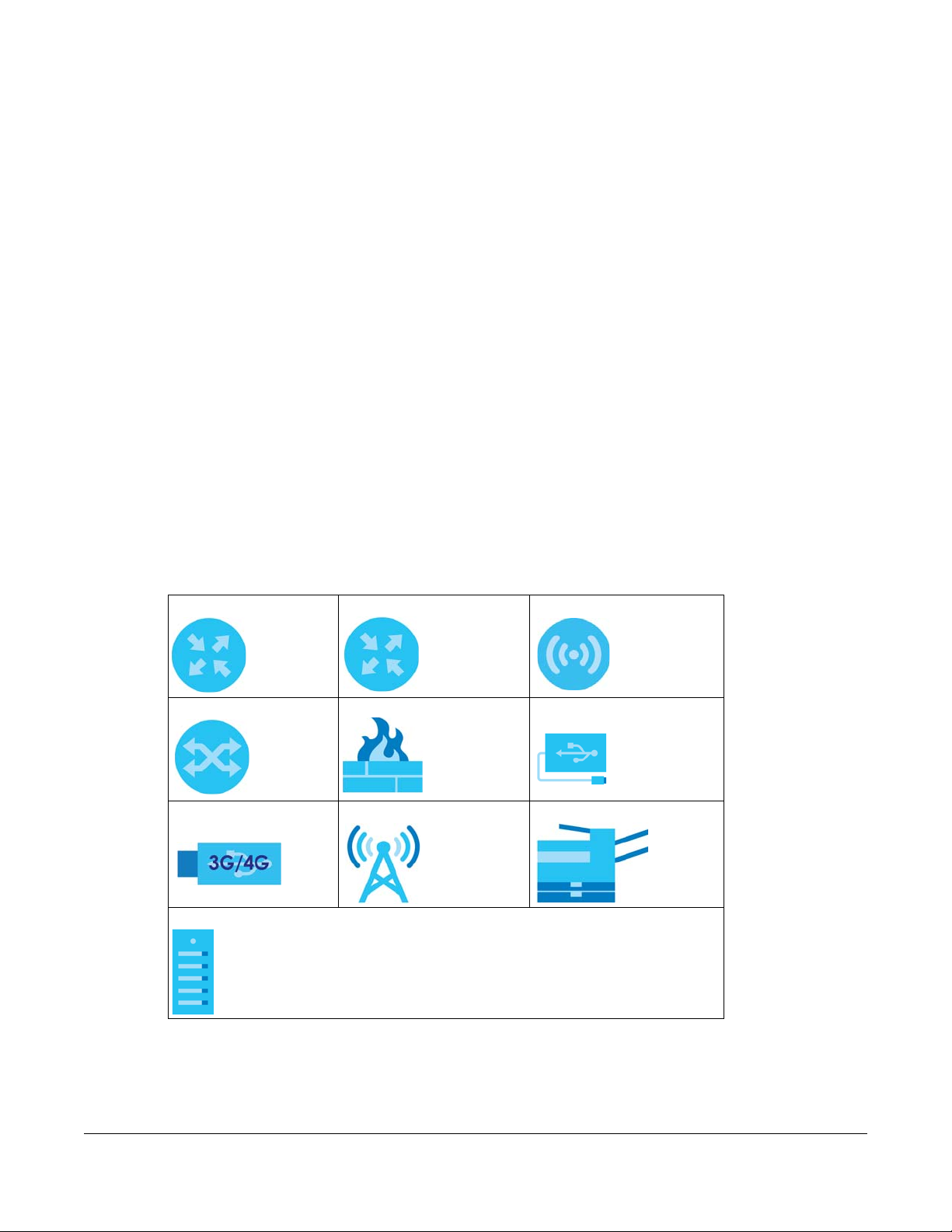
Figures in this user guide may use the following generic icons. The VPN2S icon is not an exact
representation of your device.
VPN2S Generic Router Wireless Router / Access Point
Switch Firewall USB Storage Device
USB Dongle Cell Tower Printer
Server
VPN2S User’s Guide
3
Page 4

Contents Overview
Contents Overview
User’s Guide ......................................................................................................................................13
Introducing the VPN2S ......................................................................................................................... 14
The Web Configurator ......................................................................................................................... 22
Wizard .................................................................................................................................................... 29
Technical Reference ........................................................................................................................47
Dashboard ............................................................................................................................................ 48
WAN/Internet ........................................................................................................................................ 51
LAN ......................................................................................................................................................... 78
Routing ................................................................................................................................................. 102
Network Address Translation (NAT) ................................................................................................... 116
Firewall ................................................................................................................................................. 132
Security Service ................................................................................................................................... 152
VPN ....................................................................................................................................................... 160
Bandwidth Management .................................................................................................................. 196
Network Management ...................................................................................................................... 214
System .................................................................................................................................................. 217
Log / Report ....................................................................................................................................... 219
Service / License ................................................................................................................................. 229
Device Name ...................................................................................................................................... 231
Host Name List ..................................................................................................................................... 233
Date / Time .......................................................................................................................................... 235
User Account ...................................................................................................................................... 238
USB Storage ......................................................................................................................................... 241
Diagnostic ........................................................................................................................................... 245
Firmware Upgrade .............................................................................................................................. 249
Backup / Restore ................................................................................................................................ 253
Language ............................................................................................................................................ 255
Restart / Shutdown ............................................................................................................................. 256
Troubleshooting .................................................................................................................................. 257
VPN2S User’s Guide
4
Page 5

Table of Contents
Table of Contents
Document Conventions ......................................................................................................................3
Contents Overview .............................................................................................................................4
Table of Contents .................................................................................................................................5
Part I: User’s Guide.......................................................................................... 13
Chapter 1
Introducing the VPN2S.......................................................................................................................14
1.1 Overview ......................................................................................................................................... 14
1.2 Registration at myZyxel .................................................................................................................. 14
1.3 Ways to Manage the VPN2S ......................................................................................................... 15
1.4 Good Habits for Managing the VPN2S ........................................................................................ 16
1.5 Applications for the VPN2S ............................................................................................................ 16
1.5.1 Internet Access ...................................................................................................................... 16
1.5.2 VPN2S’s USB Support ............................................................................................................. 17
1.5.3 IPv6 Routing ........................................................................................................................... 18
1.5.4 VPN Connectivity .................................................................................................................. 18
1.5.5 Load Balancing ..................................................................................................................... 19
1.6 LEDs (Lights) ..................................................................................................................................... 19
1.7 The RESET Button ............................................................................................................................. 21
Chapter 2
The Web Configurator........................................................................................................................22
2.1 Overview ......................................................................................................................................... 22
2.1.1 Accessing the Web Configurator ....................................................................................... 22
2.2 Web Configurator Layout .............................................................................................................. 24
2.2.1 Title Bar ................................................................................................................................... 25
2.2.2 Navigation Panel .................................................................................................................. 25
2.2.3 Main Window ......................................................................................................................... 28
Chapter 3
Wizard .................................................................................................................................................29
3.1 Overview ......................................................................................................................................... 29
3.2 Wizard Basic Setup ......................................................................................................................... 30
3.3 Wizard IPsec VPN Setup ................................................................................................................. 35
3.3.1 VPN Express Settings ............................................................................................................. 36
VPN2S User’s Guide
5
Page 6

Table of Contents
3.3.2 VPN Advanced Settings ....................................................................................................... 38
3.4 Wizard IPv6 Setup ........................................................................................................................... 43
Part II: Technical Reference........................................................................... 47
Chapter 4
Dashboard..........................................................................................................................................48
4.1 Overview ......................................................................................................................................... 48
4.2 The Dashboard Screen .................................................................................................................. 48
Chapter 5
WAN/Internet......................................................................................................................................51
5.1 Overview ......................................................................................................................................... 51
5.1.1 What You Can Do in this Chapter ....................................................................................... 52
5.1.2 What You Need to Know ..................................................................................................... 52
5.1.3 Before You Begin ................................................................................................................... 54
5.2 The WAN Status Screen .................................................................................................................. 55
5.3 The WAN Setup Screen .................................................................................................................. 55
5.3.1 Internet Connection: Add/Edit ............................................................................................56
5.4 The Mobile Screen .......................................................................................................................... 64
5.5 The Port Setting Screen .................................................................................................................. 68
5.6 The Multi-WAN Screen .................................................................................................................... 69
5.6.1 Multi-WAN: Edit ...................................................................................................................... 70
5.6.2 How to Configure Multi-WAN for Load Balancing and Failover ...................................... 71
5.7 The Dynamic DNS screen .............................................................................................................. 72
5.7.1 Dynamic DNS: Add/Edit ....................................................................................................... 73
5.8 Technical Reference ...................................................................................................................... 75
Chapter 6
LAN ......................................................................................................................................................78
6.1 Overview ......................................................................................................................................... 78
6.1.1 What You Can Do in this Chapter ....................................................................................... 78
6.1.2 What You Need To Know ..................................................................................................... 79
6.1.3 Before You Begin ................................................................................................................... 80
6.2 The LAN Status Screen ................................................................................................................... 80
6.3 The LAN Setup Screen .................................................................................................................... 81
6.3.1 LAN Setup: Edit ...................................................................................................................... 82
6.3.2 LAN Setup IPv6: Edit .............................................................................................................. 84
6.4 The Static DHCP Screen ................................................................................................................. 87
6.4.1 Static DHCP: Add/Edit .......................................................................................................... 87
6.5 The Additional Subnet Screen ....................................................................................................... 89
VPN2S User’s Guide
6
Page 7

Table of Contents
6.6 The Wake on LAN Screen .............................................................................................................. 89
6.6.1 Wake On LAN: Add/Edit ....................................................................................................... 90
6.7 The VLAN / Interface Group Screen ............................................................................................ 91
6.7.1 VLAN / Interface Group: Add/Edit ...................................................................................... 92
6.8 The DNS Entry Screen ..................................................................................................................... 97
6.9 The DNS Forwarder Screen ............................................................................................................ 97
6.9.1 DNS Forwarder: Add/Edit ..................................................................................................... 98
6.10 Technical Reference .................................................................................................................... 99
6.10.1 LANs, WANs and the VPN2S ............................................................................................... 99
6.10.2 DHCP Setup ......................................................................................................................... 99
6.10.3 DNS Server Addresses ....................................................................................................... 100
6.10.4 LAN TCP/IP ......................................................................................................................... 100
Chapter 7
Routing ..............................................................................................................................................102
7.1 Overview ....................................................................................................................................... 102
7.1.1 What You Can Do in this Chapter ..................................................................................... 102
7.2 The Routing Status Screen ........................................................................................................... 103
7.3 The Policy Route Screen .............................................................................................................. 109
7.3.1 Policy Route: Add/Edit ....................................................................................................... 110
7.4 The Static Route Screen ............................................................................................................... 112
7.4.1 Static Route: Add/Edit ........................................................................................................ 113
7.5 The RIP Screen ............................................................................................................................... 114
Chapter 8
Network Address Translation (NAT)................................................................................................116
8.1 Overview ....................................................................................................................................... 116
8.1.1 What You Can Do in this Chapter ..................................................................................... 116
8.1.2 What You Need To Know ................................................................................................... 116
8.2 The Port Forwarding Screen ........................................................................................................ 117
8.2.1 Port Forwarding: Add/Edit .................................................................................................. 119
8.3 The Port Triggering Screen ........................................................................................................... 120
8.3.1 Port Triggering Rule: Add/Edit ............................................................................................ 122
8.4 The Address Mapping Screen ..................................................................................................... 123
8.4.1 Address Mapping Rule: Add/Edit ...................................................................................... 124
8.5 The Default Server Screen ........................................................................................................... 125
8.5.1 Default Server: Edit .............................................................................................................. 126
8.6 The ALG Screen ............................................................................................................................ 127
8.7 Technical Reference .................................................................................................................... 128
8.7.1 NAT Definitions ..................................................................................................................... 128
8.7.2 What NAT Does ................................................................................................................... 128
8.7.3 How NAT Works .................................................................................................................... 129
8.7.4 NAT Application .................................................................................................................. 129
VPN2S User’s Guide
7
Page 8

Table of Contents
Chapter 9
Firewall ..............................................................................................................................................132
9.1 Overview ....................................................................................................................................... 132
9.1.1 What You Can Do in this Chapter ..................................................................................... 132
9.1.2 What You Need to Know ................................................................................................... 133
9.2 The Firewall Overview Screen ..................................................................................................... 134
9.3 The DoS Screen ............................................................................................................................. 134
9.4 The Firewall Rules Screen ............................................................................................................. 135
9.4.1 Firewall Rule: Add/Edit ........................................................................................................ 136
9.5 The Device Service Screen .......................................................................................................... 138
9.5.1 Device Service: Edit ............................................................................................................ 140
9.5.2 Trust Domain: Add/Edit ....................................................................................................... 140
9.6 The Zone Control Screen ............................................................................................................. 141
9.7 The Service Screen ....................................................................................................................... 142
9.7.1 Service: Add/Edit ................................................................................................................ 143
9.8 The MAC Filter Screen .................................................................................................................. 144
9.8.1 MAC Filter: Add/Edit ........................................................................................................... 145
9.9 The Certificate Screen ................................................................................................................. 146
9.10 The AAA Server ........................................................................................................................... 147
9.10.1 LDAP Server: Add/Edit ...................................................................................................... 148
9.10.2 RADIUS Server: Add/Edit ................................................................................................... 150
Chapter 10
Security Service................................................................................................................................152
10.1 Overview ..................................................................................................................................... 152
10.1.1 What You Can Do in This Chapter .................................................................................. 152
10.1.2 What You Need to Know ................................................................................................. 152
10.2 The Content Filter Screen .......................................................................................................... 153
10.2.1 Content Filter: Add/Edit .................................................................................................... 156
Chapter 11
VPN....................................................................................................................................................160
11.1 Overview ..................................................................................................................................... 160
11.2 What You Can Do in this Chapter ............................................................................................ 160
11.3 What You Need to Know ........................................................................................................... 160
11.4 The VPN Status Screen ............................................................................................................... 163
11.5 The IPsec VPN Screen ................................................................................................................ 164
11.5.1 VPN Gateway: Add/Edit .................................................................................................. 166
11.5.2 VPN Connection: Add/Edit .............................................................................................. 172
11.5.3 The Default_L2TP_VPN_GW IPsec VPN Rule ................................................................... 175
11.5.4 PPTP VPN Troubleshooting Tips ........................................................................................ 176
11.6 The PPTP VPN Screen ................................................................................................................. 177
11.6.1 PPTP VPN Troubleshooting Tips ........................................................................................ 179
VPN2S User’s Guide
8
Page 9

Table of Contents
11.7 The L2TP VPN Screen .................................................................................................................. 180
11.7.1 L2TP Setup - Server ............................................................................................................ 180
11.7.2 L2TP Setup - Client ............................................................................................................. 182
11.7.3 L2TP VPN Troubleshooting Tips ......................................................................................... 183
11.8 The L2TP Client Status Screen .................................................................................................... 186
11.9 The GRE VPN Screen .................................................................................................................. 187
11.9.1 GRE VPN: Add/Edit ........................................................................................................... 188
11.10 Technical Reference ................................................................................................................ 189
11.10.1 IPsec Architecture ........................................................................................................... 189
11.10.2 Encapsulation .................................................................................................................. 190
11.10.3 IKE Phases ........................................................................................................................ 191
11.10.4 Negotiation Mode .......................................................................................................... 192
11.10.5 IPsec and NAT ................................................................................................................. 192
11.10.6 VPN, NAT, and NAT Traversal ......................................................................................... 193
11.10.7 ID Type and Content ...................................................................................................... 194
11.10.8 Pre-Shared Key ................................................................................................................ 195
11.10.9 Diffie-Hellman (DH) Key Groups .................................................................................... 195
Chapter 12
Bandwidth Management ................................................................................................................196
12.1 Overview ..................................................................................................................................... 196
12.1.1 What You Can Do in this Chapter ................................................................................... 196
12.1.2 What You Need to Know ................................................................................................. 196
12.2 The General Screen ................................................................................................................... 198
12.3 The Queue Setup Screen ........................................................................................................... 199
12.3.1 QoS Queue: Add/Edit ...................................................................................................... 201
12.4 The Classification Setup Screen ................................................................................................ 202
12.4.1 QoS Class: Add/Edit .......................................................................................................... 203
12.5 The Policer Setup Screen ........................................................................................................... 206
12.5.1 QoS Policer: Add/Edit ....................................................................................................... 207
12.6 The Shaper Setup Screen .......................................................................................................... 208
12.6.1 QoS Shaper: Add/Edit ...................................................................................................... 209
12.7 Technical Reference .................................................................................................................. 210
Chapter 13
Network Management ....................................................................................................................214
13.1 Overview ..................................................................................................................................... 214
13.1.1 What You Can Do in This Chapter .................................................................................. 214
13.2 The SNMP Screen ........................................................................................................................ 214
Chapter 14
System...............................................................................................................................................217
14.1 Overview ..................................................................................................................................... 217
VPN2S User’s Guide
9
Page 10

Table of Contents
14.1.1 What You Can Do in This Chapter .................................................................................. 217
14.2 The Scheduler Rule Screen ........................................................................................................ 217
14.2.1 Scheduler Rule: Add/Edit ................................................................................................. 218
Chapter 15
Log / Report .....................................................................................................................................219
15.1 Overview ..................................................................................................................................... 219
15.1.1 What You Can Do in this Chapter ................................................................................... 219
15.1.2 What You Need To Know ................................................................................................. 219
15.2 The Log Viewer Screen .............................................................................................................. 220
15.3 Log Settings ................................................................................................................................. 221
15.3.1 Log on USB Settings: Edit ................................................................................................... 222
15.3.2 System and Email: Edit ...................................................................................................... 224
15.3.3 Remote Server Log Settings: Edit ..................................................................................... 226
Chapter 16
Service / License..............................................................................................................................229
16.1 Overview ..................................................................................................................................... 229
16.2 The License Screen ..................................................................................................................... 229
Chapter 17
Device Name ...................................................................................................................................231
17.1 Overview ..................................................................................................................................... 231
17.2 The Device Name Screen ......................................................................................................... 231
Chapter 18
Host Name List..................................................................................................................................233
18.1 Overview ..................................................................................................................................... 233
18.2 The Host Name List Screen ........................................................................................................ 233
18.2.1 Add Host Name ................................................................................................................. 233
Chapter 19
Date / Time .......................................................................................................................................235
19.1 Overview ..................................................................................................................................... 235
19.2 The Date / Time Screen ............................................................................................................. 235
Chapter 20
User Account....................................................................................................................................238
20.1 Overview ..................................................................................................................................... 238
20.2 What You Can Do in this Chapter ............................................................................................ 238
20.3 The User Account Screen .......................................................................................................... 238
20.3.1 Users Account: Add/Edit .................................................................................................. 239
VPN2S User’s Guide
10
Page 11

Table of Contents
Chapter 21
USB Storage ......................................................................................................................................241
21.1 Overview ..................................................................................................................................... 241
21.1.1 What You Need To Know ................................................................................................. 241
21.1.2 Before You Begin ............................................................................................................... 242
21.2 The USB Storage Screen ............................................................................................................. 242
21.2.1 Add a USB Share ............................................................................................................... 244
Chapter 22
Diagnostic.........................................................................................................................................245
22.1 Overview ..................................................................................................................................... 245
22.1.1 What You Can Do in this Chapter ................................................................................... 245
22.2 The Network Tools Screen .......................................................................................................... 245
22.3 The Packet Capture Screen ...................................................................................................... 246
Chapter 23
Firmware Upgrade ...........................................................................................................................249
23.1 Overview ..................................................................................................................................... 249
23.2 The Firmware Screen .................................................................................................................. 249
23.3 The Mobile Profile Screen .......................................................................................................... 251
Chapter 24
Backup / Restore .............................................................................................................................253
24.1 Overview ..................................................................................................................................... 253
24.2 The Backup / Restore Screen .................................................................................................... 253
Chapter 25
Language .........................................................................................................................................255
25.1 Overview ..................................................................................................................................... 255
25.2 The Language Screen ................................................................................................................ 255
Chapter 26
Restart / Shutdown...........................................................................................................................256
26.1 Overview ..................................................................................................................................... 256
26.2 The Restart / Shutdown Screen ................................................................................................. 256
Chapter 27
Troubleshooting................................................................................................................................257
27.1 Power, Hardware Connections, and LEDs ............................................................................... 257
27.2 VPN2S Access and Login ........................................................................................................... 258
27.3 Internet Access ........................................................................................................................... 260
27.4 VPN2S Configuration .................................................................................................................. 261
VPN2S User’s Guide
11
Page 12

Table of Contents
Appendix A Customer Support ..................................................................................................... 265
Appendix B Legal Information ....................................................................................................... 271
Index .................................................................................................................................................275
VPN2S User’s Guide
12
Page 13

PART I
User’s Guide
13
Page 14

1.1 Overview
The VPN2S is a VPN firewall with Gigabit Ethernet (GbE) gateway. It has two USB ports that can be used
for file sharing or using a 3G/4G dongle for cellular WAN (Internet) backup connections.
Features
• Four GbE Ports for LAN Connection
• Firewall with Secure Network Management
• Secure Access via VPN (IPsec, PPTP, L2TP)
Only use firmware for your VPN2S’s specific model. Refer to the label on
the bottom of your VPN2S.
CHAPTER 1
Introducing the VPN2S
1.2 Registration at myZyxel
myZyxel is Zyxel’s online services center where you can register your VPN2S and manage subscription
services available for your VPN2S (see Maintenance > Service / License for services available for your
VPN2S).
Note: You need to create a myZyxel account at http://portal.myZyxel.com before you can
register your device and activate the services at myZyxel.
You may need your VPN2S’s serial number and LAN MAC address to register it at
myZyxel. See the label at the back of the VPN2S’s for details.
VPN2S User’s Guide
14
Page 15
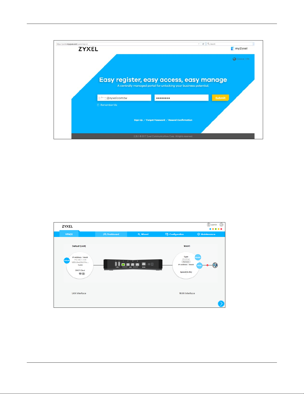
Chapter 1 Introducing the VPN2S
Figure 1 myZyxel Login
1.3 Ways to Manage the VPN2S
Use any of the following methods to manage the VPN2S.
Web Configurator
The Web Configurator allows easy VPN2S setup and management using an Internet browser. This User’s
Guide provides information about the Web Configurator.
Figure 2 Managing the VPN2S: Web Configurator
FTP
Use File Transfer Protocol for firmware upgrades and configuration backup/restore.
VPN2S User’s Guide
15
Page 16

Chapter 1 Introducing the VPN2S
SNMP
The device can be monitored and/or managed by an SNMP manager.
1.4 Good Habits for Managing the VPN2S
Do the following things regularly to make the VPN2S more secure and to manage the VPN2S more
effectively.
• Change the password. Use a password that’s not easy to guess and that consists of different types of
characters, such as numbers and letters. The password must have 6-64 printable characters [0-9][a-z]
[A-Z][!@#$%*].
• Write down the password and put it in a safe place.
• Back up the configuration (and make sure you know how to restore it). Restoring an earlier working
configuration may be useful if the device becomes unstable or even crashes. If you forget your
password, you will have to reset the VPN2S to its factory default settings. If you backed up an earlier
configuration file, you would not have to totally re-configure the VPN2S. You could simply restore your
last configuration.
1.5 Applications for the VPN2S
Here are some example uses for which the VPN2S is well suited.
1.5.1 Internet Access
As a VPN firewall your VPN2S has multiple WAN interfaces, including, 3G/4G and Gigabit Ethernet to
share the network traffic load. You can configure multiple WAN load balance and failover rules to
distribute traffic amongst the different interfaces.
If you prefer you can also use a 3G/4G dongle for cellular backup WAN (Internet) connections.
Note: If you connect all WAN ports the priority order will be Ethernet WAN port, and USB port.
VPN2S User’s Guide
16
Page 17
Chapter 1 Introducing the VPN2S
VPN2S
VPN2S
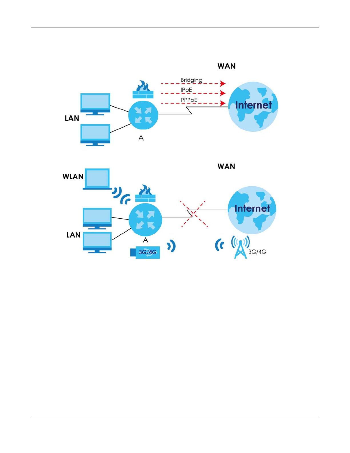
Computers can connect to the VPN2S’s LAN ports.
Figure 3 VPN2S’s Internet Access Application
Figure 4 VPN2S’s Internet Access Application: 3G/4G WAN Backup
You can also configure IP filtering on the VPN2S for secure Internet access. When the IP filter is on, all
incoming traffic from the Internet to your network is blocked by default unless it is initiated from your
network. This means that probes from the outside to your network are not allowed, but you can safely
browse the Internet and download files.
1.5.2 VPN2S’s USB Support
Use the USB port for file sharing or insert a 3G/4G dongle for cellular backup WAN (Internet) connections.
VPN2S User’s Guide
17
Page 18
Chapter 1 Introducing the VPN2S
VPN2S
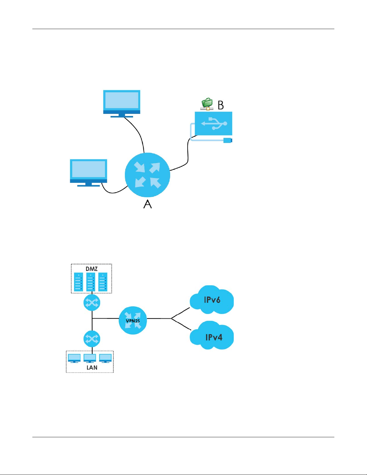
File Sharing
Use the USB port (built-in USB 2.0) to share files on USB memory sticks or USB hard drives (B). Use FTP to
access the files on the USB device.
Figure 5 USB File Sharing Application
1.5.3 IPv6 Routing
The VPN2S supports IPv6 Ethernet and PPP. You may also create IPv6 policy routes.
Figure 6 Applications: IPv6 Routing
1.5.4 VPN Connectivity
Set up VPN tunnels with other companies, branch offices, telecommuters, and business travelers to
provide secure access to your network. AS is an Authentication Server in the below figure.
VPN2S User’s Guide
18
Page 19
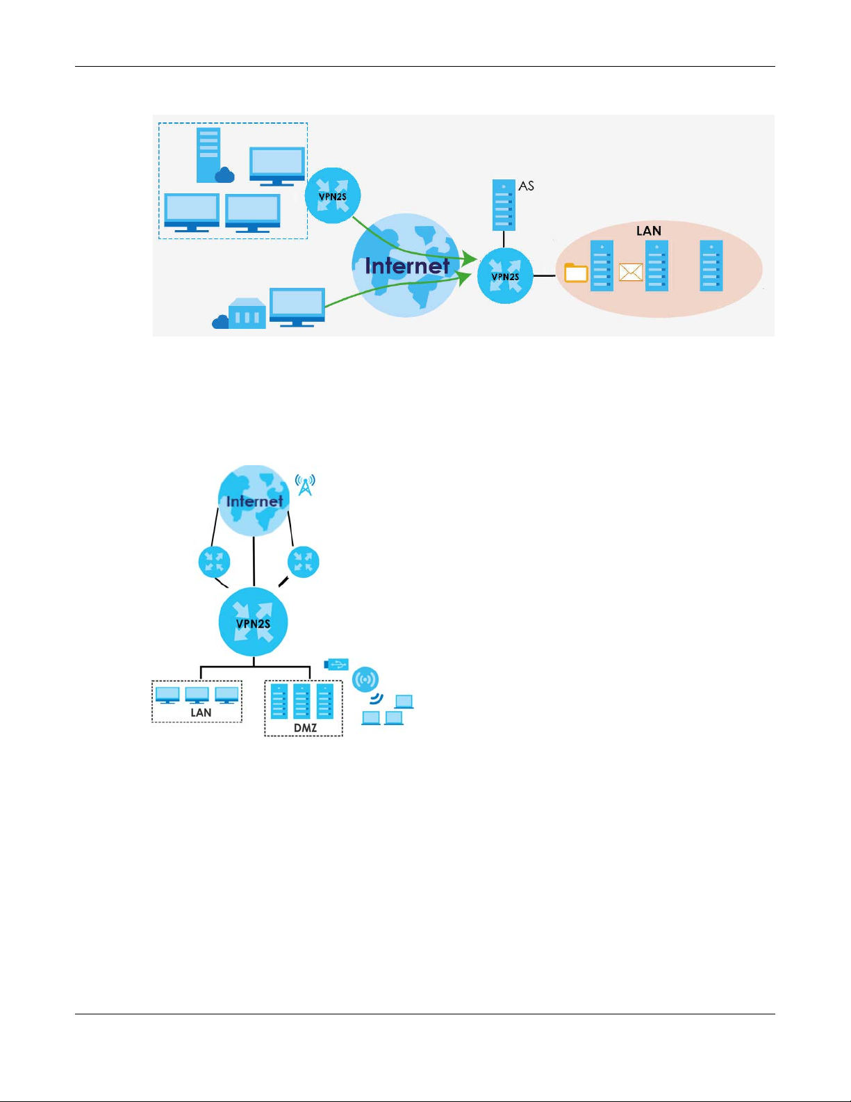
Figure 7 Applications: VPN Connectivity
1.5.5 Load Balancing
Set up multiple connections to the Internet on the same port, or different ports. In either case, you can
balance the traffic loads between them.
Figure 8 Applications: Multiple WAN Interfaces
Chapter 1 Introducing the VPN2S
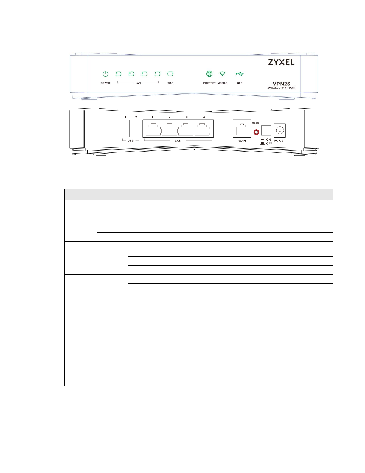
1.6 LEDs (Lights)
This section describes the LEDs on the VPN2S.
The following figure shows the front and rear panels of the VPN2S.
VPN2S User’s Guide
19
Page 20
Chapter 1 Introducing the VPN2S
Figure 9 VPN2S Front and Rear Panels
None of the LEDs are on if the VPN2S is not receiving power. The location of the LEDs are highlighted in
the figures above.
Table 1 LED Descriptions
LED COLOR STATUS DESCRIPTION
POWER Green On The VPN2S is receiving power and ready for use.
Blinking The VPN2S is self-testing.
Red On The VPN2S detected an error while self-testing, or there is a device
Off The VPN2S is not receiving power.
LAN Green On The VPN2S has a successful Ethernet connection with a device on the Local
Blinking The VPN2S is sending or receiving data to/from the LAN.
Off The VPN2S does not have an Ethernet connection with the LAN.
WAN Green On The VPN2S has a successful Ethernet connection on the WAN.
Blinking The VPN2S is sending or receiving data to/from the WAN.
Off There is no Ethernet connection on the WAN.
INTERNET Green On The VPN2S has an IP connection but no traffic.
Red On The Ethernet WAN port is connected to an Ethernet port but the VPN2S
Off There is no Internet connection or the gateway is in bridged mode.
MOBILE Green On The VPN2S recognizes a 3G/4G dongle connection in USB port 1/2.
Off The VPN2S does not detect a 3G/4G dongle connection in USB port 1/2.
USB Green On The VPN2S recognizes a USB connection in USB port 1/2.
Off The VPN2S does not detect a USB connection in USB port 1/2.
malfunction.
Area Network (LAN).
Your device has a WAN IP address (either static or assigned by a DHCP
server), PPP negotiation was successfully completed (if used).
cannot access the Internet. There is an Internet connection problem.
VPN2S User’s Guide
20
Page 21

Table 1 LED Descriptions (continued)
LED COLOR STATUS DESCRIPTION
ETHERNET
LAN 1-4 (On
Connector)
Green
(Left LED)
1GM
Amber
(Right LED)
10-100M
On The VPN2S has a successful Ethernet connection with a device on the Local
Blinking The VPN2S is sending or receiving data to/from the LAN.
Off The VPN2S does not have an Ethernet connection with the LAN.
On The VPN2S has a successful Ethernet connection with a device on the Local
Blinking The VPN2S is sending or receiving data to/from the LAN.
Off The VPN2S does not have an Ethernet connection with the LAN.
1.7 The RESET Button
If you forget your password or cannot access the web configurator, you will need to use the RESET
button at the back of the device to reload the factory-default configuration file. This means that you will
lose all configurations that you had previously and the password will be reset to “1234”.
Chapter 1 Introducing the VPN2S
Area Network (LAN).
Area Network (LAN).
1 Make sure the POWER LED is on (not blinking).
2 To set the device back to the factory default settings, press the RESET button for five seconds or until the
POWER LED begins to blink and then release it. When the POWER LED begins to blink, the defaults have
been restored and the device restarts.
VPN2S User’s Guide
21
Page 22
The Web Configurator
2.1 Overview
The web configurator is an HTML-based management interface that allows easy device setup and
management via Internet browser. Use Internet Explorer 10.0 and later versions, Mozilla Firefox 45 and
later versions, Google Chrome 45 and later versions, and Safari 9.0 and later versions. The
recommended screen resolution is 1024 by 768 pixels.
In order to use the web configurator you need to allow:
• Allow pop-up windows from your device (blocked by default in some Internet browsers).
• JavaScript (enabled by default).
• Java permissions (enabled by default).
2.1.1 Accessing the Web Configurator
CHAPTER 2
1 Make sure your VPN2S hardware is properly connected (refer to the Quick Start Guide).
2 Launch your web browser. If the VPN2S does not automatically re-direct you to the login screen, go to
http://192.168.1.1.
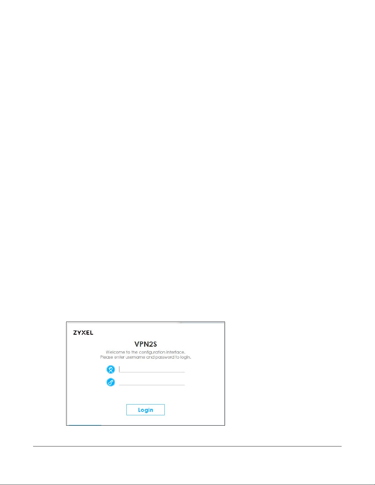
3 A password screen displays. To access the administrative web configurator and manage the VPN2S,
type the default username admin and password 1234 in the password screen and click Login. If
advanced account security is enabled (see Section 20.3 on page 238) the number of dots that appears
when you type the password changes randomly to prevent anyone watching the password field from
knowing the length of your password. If you have changed the password, enter your password and click
Login.
Figure 10 Password Screen
VPN2S User’s Guide
22
Page 23
Chapter 2 The Web Configurator
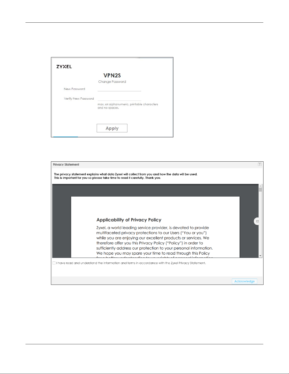
4 The following screen displays if you have not yet changed your password from the default. Enter a new
password, retype it to confirm and click Apply. After changing the password your VPN2S will log out
automatically. so you can log in with your new password.
Figure 11 Change Password Screen
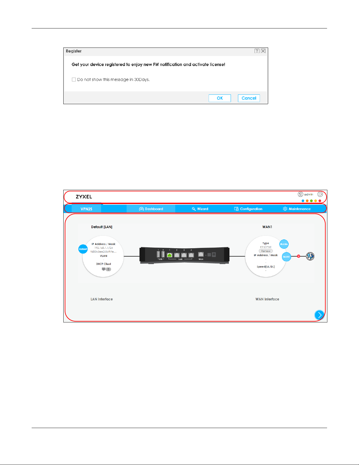
5 The Privacy Statement screen appears automatically after login. Click on the check box to agree to all
the terms and click Acknowledge.
Figure 12 Privacy Statement Screen
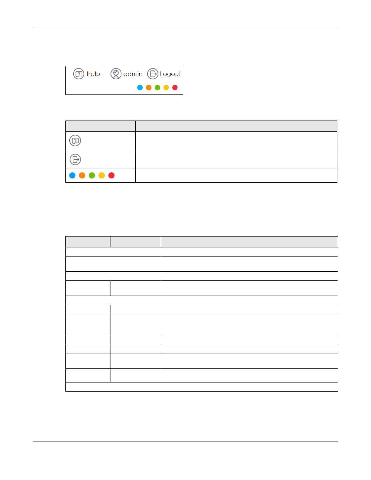
6 The Register screen appears after the Privacy Statement screen. Click OK in the Register screen to
register the VPN2S at myzyxel.com.
VPN2S User’s Guide
23
Page 24
Chapter 2 The Web Configurator
B
A
C
Figure 13 Register Screen
7 The Wizard appears after the Register screen. Use the Wizard to configure VPN2S’s basic settings. See
Chapter 3 on page 29 for more information.
8 The Dashboard page appears after the Wizard set up, here you can view the VPN2S’s interface and
system information.
2.2 Web Configurator Layout
Figure 14 Screen Layout
As illustrated above, the main screen is divided into these parts:
• A - title bar
• B - navigation panel
• C - main window
VPN2S User’s Guide
24
Page 25
2.2.1 Title Bar
The title bar provides some icons in the upper right corner.
The icons provide the following functions.
Table 2 Web Configurator Icons in the Title Bar
ICON DESCRIPTION
2.2.2 Navigation Panel
Chapter 2 The Web Configurator
Help: Click this icon to view a description of the screen you are currently using.
Logout: Click this icon to log out of the web configurator.
Click a color from the palette to change the color of your web configurator.
Use the menu items on the navigation panel to open screens to configure VPN2S features. The following
tables describe each menu item.
Table 3 Navigation Panel Summary
LINK TAB FUNCTION
Dashboard Click this to go to the main Web Configurator screen.
Wizard Use this screen to configure the VPN2S’s basic settings. For more
information see Chapter 3 on page 29.
Configuration
Configuration
Site Map
WAN / Internet
WAN Status Use this screen to view the WAN ports’ status.
WAN Setup Use this screen to view and configure ISP parameters, WAN IP address
Mobile Use this screen to configure the mobile 3G/4G connection.
Port Setting Use this screen to set flexible ports as part of LAN or WAN interfaces.
Multi-WAN Use this screen to configure the multiple WAN load balance and failover
Dynamic
DNS
LAN / Home Network
Click this to view a summary of all the available screens in the
Configuration menu.
assignment, and other advanced properties. You can also add new WAN
connections.
rules to distribute traffic among different interfaces.
Use this screen to allow a static hostname alias for a dynamic IP address.
VPN2S User’s Guide
25
Page 26

Chapter 2 The Web Configurator
Table 3 Navigation Panel Summary (continued)
LINK TAB FUNCTION
LAN Status LAN Status Use this screen to view the status of all network traffic going through the
LAN ports of the VPN2S.
DHCP Client Use this screen to view the status of all devices connected to the VPN2S.
You can also set screen refresh time to see updates on new devices.
ARP Table Use this screen to view the ARP table. It displays the IP and MAC address
Multicast Status Use this screen to look at IGMP/MLD group status and traffic statistics.
LAN Setup Use this screen to configure LAN TCP/IP settings, and other advanced
Static DHCP Use this screen to assign specific IP addresses to individual MAC
Additional
Subnet
Wake on LAN Use this screen to remotely wake up a hibernating device on the local
VLAN /
Interface
Group
DNS Entry Use this screen to view and configure a domain name and DNS routes on
DNS
Forwarder
Routing
Routing
Status
Policy Route Use this screen to view and set up policy routes on the VPN2S.
Static Route Use this screen to view and set up static routes on the VPN2S.
RIP Use this screen to set up RIP (Routing Information Protocol) settings on the
NAT
Port
Forwarding
Port
Triggering
Address
Mapping
Default
Server
ALG Use this screen to enable or disable NAT ALG and SIP ALG.
Firewall / Security
Firewall
Overview
DoS Use this screen to activate protection against Denial of Service (DoS)
Firewall Rules Use this screen to add and view existing firewall rules to the VPN2S.
Device
Service
Zone Control Use this screen to set the firewall’s default actions based on the direction
of each DHCP connection.
properties.
addresses.
Use this screen to configure IP alias.
network.
Use this screen to create a new interface group, which is a new LAN
bridge interface (subnet).
the VPN2S.
Use this screen to view and configure domain zone forwarder on the
VPN2S.
Use this screen to view the IPv4 and IPv6 routing flow.
VPN2S.
Use this screen to make your local servers visible to the outside world.
Use this screen to change your VPN2S’s port triggering settings.
Use this screen to change your VPN2S’s address mapping settings.
Use this screen to configure a default server which receives packets from
ports that are not specified in the Port Forwarding screen.
Use this screen to enable the firewall.
attacks.
Use this screen to manage the services (such as HTTP and SSH) in the
VPN2S.
of travel of packets.
VPN2S User’s Guide
26
Page 27

Chapter 2 The Web Configurator
Table 3 Navigation Panel Summary (continued)
LINK TAB FUNCTION
Service Use this screen to add Internet services.
MAC Filter Use this screen to block or allow traffic from devices of certain MAC
addresses to the VPN2S.
Certificate Use this screen to view a summary list of certificates and manage
certificates and certification requests.
AAA Server Use this screen to manage the list of LDAP and RADIUS servers the VPN2S
Security Service
Content Filter Use this screen to control access to specific websites or web content.
VPN
VPN Status Use this screen to look at the status of VPN tunnels that are currently
IPsec VPN Use this screen to display and manage IPsec VPN gateways and
PPTP VPN Use this screen to configure the PPTP VPN settings in the VPN2S.
L2TP VPN Use this screen to configure L2TP over IPsec tunnels.
L2TP Client
Status
GRE VPN Use this screen to configure the GRE VPN settings in the VPN2S.
Bandwidth Management
General Use this screen to enable QoS and traffic prioritizing. You can also
Queue Setup Use this screen to configure QoS queues.
Classification
Setup
Policer Setup Use these screens to configure QoS policers.
Shaper Setup Use this screen to limit outgoing traffic transmission rate on the selected
Network Management
SNMP Use this screen to configure SNMP communities and services.
System
Scheduler
Rule
Log/Report
Log Viewer Use this screen to view the system logs on the VPN2S.
Log Settings Use this screen to change specify settings to recording your logs on the
Maintenance
Maintenance
Site Map
Service / License Use this screen to view the status of your licenses and update any license
Device Name Use this screen to give your VPN2S a name.
Host Name List Use this screen to add connected devices to the VPN2S.
Date / Time Use this screen to change your VPN2S’s time and date.
can use in authenticating users.
established.
connections.
Use this screen to view details about the L2TP clients.
configure the QoS rules and actions.
Use this screen to define a classifier.
interface.
Use this screen to configure the days and times when a configured
restriction (such as User Access control) is enforced.
VPN2S.
Click this to view a summary of all the available screens in the
Maintenance menu.
information.
VPN2S User’s Guide
27
Page 28
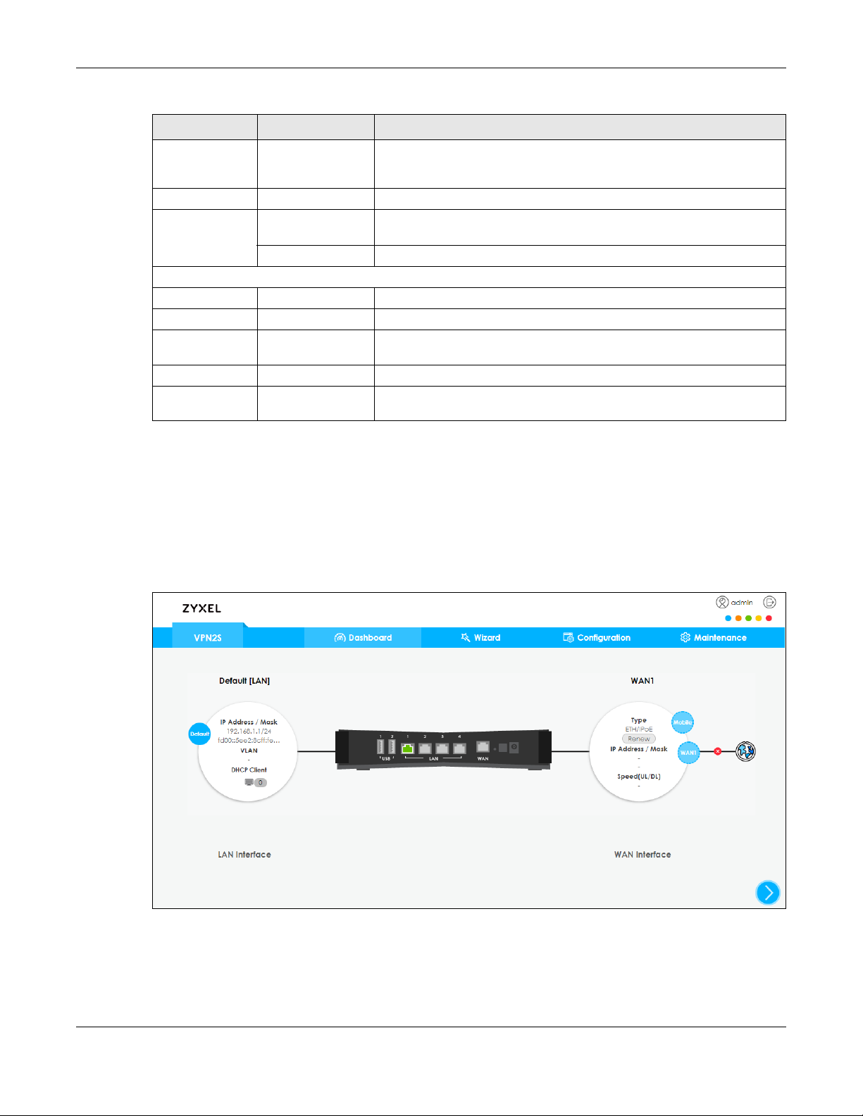
Table 3 Navigation Panel Summary (continued)
LINK TAB FUNCTION
User Account Use this screen to manage user accounts, which includes configuring the
USB Storage Use this screen to enable USB storage sharing.
Diagnostic Network Tools Use this screen to ping an IP address or trace the route packets take to a
Firmware Upgrade
Firmware Use this screen to upload firmware to your device.
Mobile Profile Use this screen to update the mobile profile on the VPN2S.
Backup / Restore Use this screen to backup and restore your device’s configuration
Language Use this screen to change the VPN2S web configurator’s language,
Restart /
Shutdown
2.2.3 Main Window
Chapter 2 The Web Configurator
username, password, retry times, file sharing, captive portal, and
customizing the login message.
host
Packet Capture Use this screen to capture packets going through the VPN2S.
(settings) or reset the factory default settings.
Use this screen to reboot the VPN2S without turning the power off.
The main window displays information and configuration fields. It is discussed in the rest of this
document.
If you click Dashboard a graphic shows the connection status of the VPN2S’s ports. The connected
interfaces are in color and disconnected interfaces are gray.
Figure 15 Dashboard Screen
VPN2S User’s Guide
28
Page 29
3.1 Overview
The Web Configurator's quick setup Wizard helps you configure Internet and VPN connection settings.
This chapter provides information on configuring the Wizard screens in the Web Configurator. See the
feature-specific chapters in this User’s Guide for background information.
Before you begin configuring your VPN2S register your device at myZyxel portal and check your current
license status.
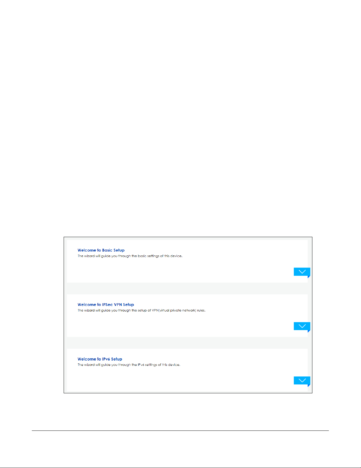
The Wizard consists of the following setups:
• Wizard Basic Setup - Use Basic Setup to set up a WAN (Internet) connection. This Wizard creates
matching ISP account settings in the VPN2S if you use PPPoE. See Section 3.2 on page 30.
• Wizard IPsec VPN Setup - Use IPsec VPN Setup to configure an IPsec VPN (Virtual Private Network) rule
for a secure connection to another computer or network. See Section 3.3 on page 35.
• Wizard IPv6 Setup - Use IPv6 Setup to configure the IPv6 settings on your VPN2S. See Section 3.4 on
page 43.
Figure 16 Wizard Setup
CHAPTER 3
Wizard
Note: See the technical reference chapters (starting on page 47) for background information
on the features in this chapter.
VPN2S User’s Guide
29
Page 30
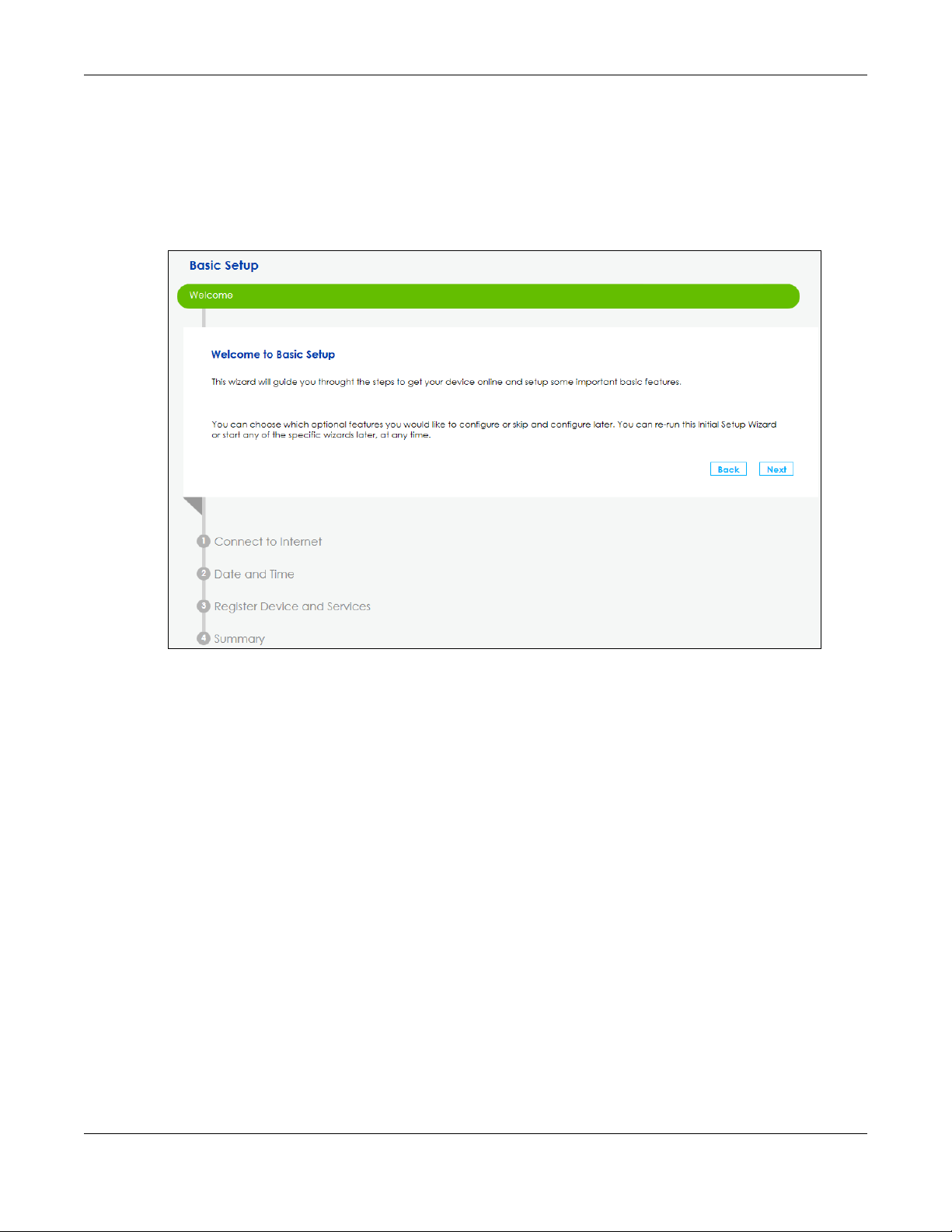
3.2 Wizard Basic Setup
The Wizard appears automatically after you log in the first time. Or you can go to the Wizard tab in the
navigation panel. Click the Welcome to Basic Setup down arrow to configure an interface to connect
to the Internet. Click Next to continue the Wizard, Back to return to the previous screen.
Figure 17 Wizard Basic Setup
Chapter 3 Wizard
1 Enter your Internet connection information in this screen. The screen and fields to enter may vary
depending on your current connection type and the Encapsulation you choose. You can also use this
screen to enable the VLAN tag in the VPN2S. Assign it a priority level (802.1p) and a VLAN ID for traffic
through this connection. Click Next.
VPN2S User’s Guide
30
Page 31

Figure 18 Connect to the Internet
Chapter 3 Wizard
2 If you select PPPoE as your encapsulation, type the Username given to you by your ISP and type the
Password associated with the user name.
Figure 19 PPP information
3 Use this screen to specify which IPv4 address the VPN2S uses to connect to the Internet. If your ISP gave
you this information, enter it here. Otherwise select Obtain an IP Address Automatically.
VPN2S User’s Guide
31
Page 32

Figure 20 IPv4 Address
Chapter 3 Wizard
4 Choose whether VPN2S gets DNS server addresses from the ISP automatically or uses the DNS server
addresses you got from the ISP. A DNS server is used for mapping a domain name to its corresponding IP
address and vice versa.
Figure 21 DNS Server
5 Choose the time zone for your device’s location. Click Save.
VPN2S User’s Guide
32
Page 33

Chapter 3 Wizard
Figure 22 Date and Time
6 The VPN2S saves your settings and attempts to connect to the Internet. If the VPN2S failed to connect to
the Internet or if you want to modify any of the settings you previously configured you can click Back or
go to the Configuration > WAN/Internet > WAN Setup screen. Click Connection Test for the VPN2S to try
reconnecting with the same settings.
Figure 23 Basic Setup Completed
7 You can register your device and manage subscription services available for your VPN2S at myZyxel
portal for online services.
VPN2S User’s Guide
33
Page 34

Chapter 3 Wizard
Figure 24 Register Device and Services
8 You can check your service license status. Click the Refresh button to renew service license status.
Figure 25 Register Device and Services
9 Once you completed the basic setup a summary of your settings displays. Click Finish to continue with
the Wizard setup.
VPN2S User’s Guide
34
Page 35

Chapter 3 Wizard
Figure 26 Summary
3.3 Wizard IPsec VPN Setup
Click the IPsec VPN Setup down arrow to configure a VPN (Virtual Private Network) rule for a secure
connection to another computer or network.
Figure 27 Wizard IPsec VPN Setup
There are two types of VPN policies you can configure in the VPN2S. Select one and click Next.
•Express - Select Express to create a VPN rule with the default phase 1 and phase 2 settings and use a
pre-shared key as the authentication method. See Section 3.3.1 on page 36.
VPN2S User’s Guide
35
Page 36

Chapter 3 Wizard
• Advanced - Select Advanced to change default settings an/or use certificates instead of a preshared key in the VPN rule. See Section 3.3.2 on page 38.
Figure 28 VPN Policy Type
3.3.1 VPN Express Settings
The following screens will display if you select Express in the previous screen.
1 Type the Rule Name used to identify this VPN connection (and VPN gateway). Then select the IKE
Version and Scenario that best describes your intended VPN connection. For more information on each
label see Section 11.5 on page 164.
VPN2S User’s Guide
36
Page 37

Figure 29 VPN Express Settings
Chapter 3 Wizard
2 In My Interface select the type of encapsulation this connection is to use. Configure a Secure Gateway
IP as the peer VPN2S’s WAN IP address. Type a secure Pre-Shared Key. Set Local Policy to be the IP
address range of the network connected to the VPN2S and Remote Policy to be the IP address range of
the network connected to the peer VPN2S.
Figure 30 Secure Gateway
VPN2S User’s Guide
37
Page 38

Chapter 3 Wizard
3 This screen shows a read-only summary of the VPN tunnel’s configuration. Click Save to apply your
changes.
Figure 31 Summary
4 Your VPN2S saves your settings. Now the VPN rule is configured on the VPN2S.
Figure 32 VPN Express Settings Completed
3.3.2 VPN Advanced Settings
The following screens will display if you select Advanced in the VPN Policy screen.
1 Type the Rule Name used to identify this VPN connection (and VPN gateway). Then select the IKE
Version and the Scenario that best describes your intended VPN connection. Then click Next. For more
information on each label see Section 11.5 on page 164.
VPN2S User’s Guide
38
Page 39

Figure 33 VPN Advanced Settings
Chapter 3 Wizard
2 Use the following screen to setup Phase 1 Settings. Select an Encryption, Authentication Algorithm, and
Key Group, and define how often the VPN2S renegotiates the IKE SA in the Life Time field. For more
information on each label see Section 11.5 on page 164.
VPN2S User’s Guide
39
Page 40

Figure 34 Phase 1 Settings
Chapter 3 Wizard
3 Use the following screen to setup Phase 2 Settings. Phase 2 in an IKE uses the SA that was established in
phase1 to negotiate Security Associations (SAs) for IPsec. For more information on each label on this
screen see Section 11.5 on page 164. Click Next.
VPN2S User’s Guide
40
Page 41

Figure 35 Phase 2 Settings
Chapter 3 Wizard
4 A read-only summary of the VPN tunnel’s configuration will display. If you want to save your changes
click Save; otherwise go Back to modify any previous configurations.
VPN2S User’s Guide
41
Page 42

Figure 36 Summary
Chapter 3 Wizard
5 Your VPN2S saves your settings. Now the rule is configured on the VPN2S. Click Finish to exit the VPN
Setup Wizard.
VPN2S User’s Guide
42
Page 43

Chapter 3 Wizard
Figure 37 VPN Advanced Settings Completed
3.4 Wizard IPv6 Setup
Click the IPv6 Setup down arrow to configure the IPv6 settings on the VPN2S. Click Next to continue the
Wizard, Back to return to the previous screen.
VPN2S User’s Guide
43
Page 44

Chapter 3 Wizard
Figure 38 Wizard IPv6 Setup
6 Select the WAN interface on which you want to have an IPv6 connection. Select Auto Detection for the
VPN2S to automatically detect the IPv6 Internet connection type, and the Wizard IPv6 setup is
completed. If you want to enter a static IPv6 address or obtain it from a DHCP server click Next.
Figure 39 Interface Setup
7 If you did not select Auto Detection the following screen displays. Use this screen to enter a static IPv6
address assigned by your ISP, and/or obtain an IPv6 address from a DHCPv6 server. The IP address
assigned by a DHCP server has priority over the IP address automatically generated by the VPN2S.
VPN2S User’s Guide
44
Page 45

Figure 40 WAN Setup
Chapter 3 Wizard
8 Use this screen to configure the LAN IPv6 settings of the VPN2S. Select Delegate Prefix From WAN to
automatically obtain an IPv6 network prefix from the previously selected interface. Or select Static to
configure a static IPv6 address for the VPN2S’s LAN IPv6 address. Select the type of service that you are
registered from your DNS service provider. Click Next to save your settings.
Figure 41 LAN Setup
VPN2S User’s Guide
45
Page 46

Chapter 3 Wizard
9 A read-only summary of the IPv6 settings will display. Click Finish to exit the Wizard IPv6 Setup.
Figure 42 Summary
VPN2S User’s Guide
46
Page 47

PART II
Technical Reference
47
Page 48

4.1 Overview
After you log into the Web Configurator, the Dashboard screen appears. This shows the network
connection status of the VPN2S and clients connected to it.
You can use the Dashboard screen to look at the current status of the VPN2S, system resources, and
interfaces (LAN and WAN).
4.2 The Dashboard Screen
Use this screen to view the connections status of the VPN2S. When you click the Dashboard tab a
network map opens. You can view the number of devices connected to the VPN2S. Click on each
interface icon to view details about the VPN2S interfaces.
CHAPTER 4
Dashboard
Figure 43 Dashboard Screen
If you prefer to view the status in a list, click the arrow icon to show the Dashboard’s list view.
VPN2S User’s Guide
48
Page 49

Chapter 4 Dashboard
Figure 44 Dashboard List View Screen
Each field is described in the following table.
Table 4 Dashboard List View Screen
LABEL DESCRIPTION
Device Information
Host Name This field displays the name used to identify the VPN2S on any network.
Serial Number This field displays the serial number of this VPN2S. The serial number is used for device
tracking and control.
MAC Address This field displays the MAC address used by the VPN2S.
Firmware Version This field displays the present firmware version.
System Status
System Uptime This field displays how long the VPN2S has been running since it last restarted or was
turned on.
Current Date / Time This field displays the time in the VPN2S.
Each time you reload this page, the VPN2S synchronizes the date with the time
server.
CPU Usage This field displays what percentage of the VPN2S’s processing capability is currently
Memory Usage This field displays what percentage of the VPN2S’s RAM is currently being used.
Firewall Status
Firewall Click the slide button to enable and disable the firewall on the VPN2S.
DoS Protection Click the slide button to activate protection against DoS attacks.
Multi-WAN
Load Balance This shows the active WAN interfaces in the VPN2S.
being used.
VPN2S User’s Guide
49
Page 50

Chapter 4 Dashboard
Table 4 Dashboard List View Screen
LABEL DESCRIPTION
Algorithm This field displays the type of load balancing algorithm currently used by the VPN2S.
WRR (Weighted Round Robin) to balance the traffic load between interfaces based
on their respective weights.
LLF (Least Load First) to send new session traffic through the least utilized trunk
member.
SPILLOVER to send network traffic through the first interface in the group member list
until there is enough traffic that the second interface needs to be used (and so on).
Failover This field displays the passive interfaces used for failover in the VPN2S.
VPN Status This field displays the VPN2S’s VPN connections and if the IP Sec SA is connected or
disconnected.
Dynamic DNS Status This field display the VPN2S’s dynamic DNS and the interface each DDNS uses.
Bandwidth Monitor
Interface This field displays the name of each interface in the VPN2S.
Upload Speed This displays interface’s current upload link speed.
Download Speed This displays interface’s current download link speed.
Content Filter Statistics
Web Request Statistics This displays the number of websites the VPN2S has grant access to versus the
websites that have been blocked according to what you have selected in the
Configuration > Security Service> Content Filter screen.
Category Hit Summary This displays the number of requested managed web pages versus the ones with
Content Filter Top Query List This displays the top categories of the web pages accessed by the VPN2S
security threat categories you have selected in the Configuration > Security Service>
Content Filter screen.
VPN2S User’s Guide
50
Page 51

5.1 Overview
VPN2S
VPN2S
This chapter discusses the VPN2S’s WAN/Internet screens. Use these screens to configure your VPN2S for
Internet access.
A WAN (Wide Area Network) connection is an outside connection to another network or the Internet. It
connects your private networks, such as a LAN (Local Area Network) and other networks, so that a
computer in one location can communicate with computers in other locations.
Figure 45 LAN and WAN
CHAPTER 5
WAN/Internet
3G (third generation)/4G (fourth generation) standards are used for the sending and receiving of voice,
video, and data in a mobile environment.
You can attach a 3G/4G wireless adapter to the USB port and set the VPN2S to use this 3G/4G
connection as your WAN or a backup when the wired WAN connection fails.
Figure 46 Mobile WAN Connection
VPN2S User’s Guide
51
Page 52

Chapter 5 WAN/Internet
5.1.1 What You Can Do in this Chapter
• Use the WAN Status screen to view the WAN traffic statistics (Section 5.3 on page 55).
• Use the WAN Setup screen to view, remove or add a WAN interface. You can also configure the WAN
settings on the VPN2S for Internet access (Section 5.3 on page 55).
• Use the Mobile screen to configure a 3G/4G WAN connection (Section 5.4 on page 64).
• Use the Port Setting screen to set flexible ports as part of LAN or WAN interfaces. (Section 5.5 on page
68).
• Use the Multi-WAN screen to configure the multiple WAN load balancing and failover rules to
distribute traffic among different interfaces (Section 5.6 on page 69).
• Use the Dynamic DNS screen to enable DDNS and configure the DDNS settings on the VPN2S (Section
5.7 on page 72).
Table 5 WAN Setup Overview
LAYER-2 INTERFACE INTERNET CONNECTION
CONNECTION MODE ENCAPSULATION CONNECTION SETTINGS
Ethernet Routing IPoE/PPPoE PPP information, IPv4/IPv6 IP address, routing
Bridge N/A VLAN and QoS
3G Nailed Up PPP/IPoE Dial string, APN (Access Point Name), IP
On Demand PPP/IPoE Dial string, APN, Maximum idle time out, IP
feature, DNS server, VLAN, QoS, and MTU
address, DNS server
address, DNS server
5.1.2 What You Need to Know
The following terms and concepts may help as you read this chapter.
Encapsulation Method
Encapsulation is used to include data from an upper layer protocol into a lower layer protocol. To set up
a WAN connection to the Internet, you need to use the same encapsulation method used by your ISP
(Internet Service Provider). If your ISP offers a dial-up Internet connection using PPPoE (PPP over
Ethernet), they should also provide a username and password (and service name) for user
authentication.
WAN IP Address
The WAN IP address is an IP address for the VPN2S, which makes it accessible from an outside network. It
is used by the VPN2S to communicate with other devices in other networks. It can be static (fixed) or
dynamically assigned by the ISP each time the VPN2S tries to access the Internet.
If your ISP assigns you a static WAN IP address, they should also assign you the subnet mask and DNS
server IP address(es).
3G / 4G
3G (Third Generation)/ 4G(Fourth Generation) is a digital, packet-switched wireless technology.
Bandwidth usage is optimized as multiple users share the same channel and bandwidth is only
VPN2S User’s Guide
52
Page 53

Chapter 5 WAN/Internet
allocated to users when they send data. It allows fast transfer of voice and non-voice data and provides
broadband Internet access to mobile devices.
IPv6 Introduction
IPv6 (Internet Protocol version 6), is designed to enhance IP address size and features. The increase in
IPv6 address size to 128 bits (from the 32-bit IPv4 address) allows up to 3.4 x 10
can use IPv4/IPv6 dual stack to connect to IPv4 and IPv6 networks, and supports IPv6 rapid deployment
(6RD).
38
IP addresses. The VPN2S
IPv6 Addressing
The 128-bit IPv6 address is written as eight 16-bit hexadecimal blocks separated by colons (:). This is an
example IPv6 address 2001:0db8:1a2b:0015:0000:0000:1a2f:0000.
IPv6 addresses can be abbreviated in two ways:
• Leading zeros in a block can be omitted. So 2001:0db8:1a2b:0015:0000:0000:1a2f:0000 can be
written as 2001:db8:1a2b:15:0:0:1a2f:0.
• Any number of consecutive blocks of zeros can be replaced by a double colon. A double colon can
only appear once in an IPv6 address. So 2001:0db8:0000:0000:1a2f:0000:0000:0015 can be
written as 2001:0db8::1a2f:0000:0000:0015, 2001:0db8:0000:0000:1a2f::0015,
2001:db8::1a2f:0:0:15 or 2001:db8:0:0:1a2f::15.
IPv6 Prefix and Prefix Length
Similar to an IPv4 subnet mask, IPv6 uses an address prefix to represent the network address. An IPv6
prefix length specifies how many most significant bits (start from the left) in the address compose the
network address. The prefix length is written as “/x” where x is a number. For example,
2001:db8:1a2b:15::1a2f:0/32
means that the first 32 bits (2001:db8) is the subnet prefix.
IPv6 Subnet Masking
Both an IPv6 address and IPv6 subnet mask compose of 128-bit binary digits, which are divided into
eight 16-bit blocks and written in hexadecimal notation. Hexadecimal uses four bits for each character
(1 ~ 10, A ~ F). Each block’s 16 bits are then represented by four hexadecimal characters. For example,
FFFF:FFFF:FFFF:FFFF:FC00:0000:0000:0000.
IPv6 Rapid Deployment
Use IPv6 Rapid Deployment (6rd) when the local network uses IPv6 and the ISP has an IPv4 network.
When the VPN2S has an IPv4 WAN address and you set IPv4/IPv6 Mode to IPv4 Only, you can enable 6rd
to encapsulate IPv6 packets in IPv4 packets to cross the ISP’s IPv4 network.
The VPN2S generates a global IPv6 prefix from its IPv4 WAN address and tunnels IPv6 traffic to the ISP’s
Border Relay router (BR in the figure) to connect to the native IPv6 Internet. The local network can also
use IPv4 services. The VPN2S uses it’s configured IPv4 WAN IP to route IPv4 traffic to the IPv4 Internet.
VPN2S User’s Guide
53
Page 54

Chapter 5 WAN/Internet
VPN2S
VPN2S
Figure 47 IPv6 Rapid Deployment
Dual Stack Lite
Use Dual Stack Lite when local network computers use IPv4 and the ISP has an IPv6 network. When the
VPN2S has an IPv6 WAN address and you set IPv4/IPv6 Mode to IPv6 Only, you can enable Dual Stack
Lite to use IPv4 computers and services.
The VPN2S tunnels IPv4 packets inside IPv6 encapsulation packets to the ISP’s Address Family Transition
Router (AFTR in the graphic) to connect to the IPv4 Internet. The local network can also use IPv6 services.
The Router uses it’s configured IPv6 WAN IP to route IPv6 traffic to the IPv6 Internet.
Figure 48 Dual Stack Lite
5.1.3 Before You Begin
You need to know your Internet access settings such as encapsulation and WAN IP address. Get this
information from your ISP.
VPN2S User’s Guide
54
Page 55

Chapter 5 WAN/Internet
5.2 The WAN Status Screen
Use this screen to show the number of bytes received and sent on the VPN2S. Click Configuration > WAN
/ Internet to open the WAN Status screen.
Figure 49 Configuration > WAN / Internet > WAN Status
The following table describes the labels in this screen.
Table 6 Configuration > WAN / Internet > WAN Status
LABEL DESCRIPTION
Refresh Click this to update the table.
Name This displays the name of the WAN interface.
Status This shows Up if the connection to this interface is up, otherwise it will display Down.
Tx Bytes This indicates the number of bytes transmitted on this interface.
Rx Bytes This indicates the number of bytes received on this interface.
Tx Pkts This indicates the number of transmitted packets on this interface.
Rx Pkts This indicates the number of received packets on this interface.
5.3 The WAN Setup Screen
Use this screen to change your VPN2S’s Internet access settings. Click Configuration > WAN / Internet >
WAN Setup from the menu. The summary table shows you the configured WAN services (connections)
on the VPN2S.
Figure 50 Configuration > WAN / Internet > WAN Setup
VPN2S User’s Guide
55
Page 56

Chapter 5 WAN/Internet
The following table describes the labels in this screen.
Table 7 Configuration > WAN / Internet > WAN Setup
LABEL DESCRIPTION
Add Click this button to create a new WAN connection.
Edit Click Edit to modify the WAN connection.
Remove Click Remove to delete a WAN connection.
Multiple Entries
Turn On
Multiple Entries
Turn Off
# This is the index number of the WAN connection.
Status This field displays whether the connection is active or not. A green ON button signifies that this
Name This is the service name of the connection.
Type This shows Ethernet connection.
Mode This shows whether the connection is in routing or bridge mode.
Encapsulation This is the method of encapsulation used by this connection.
802.1p This indicates the IEEE 802.1p priority level assigned to traffic sent through this connection. This
802.1q This indicates the VLAN ID number assigned to traffic sent through this connection. This displays
IGMP Proxy This shows whether the VPN2S act as an IGMP proxy (green check mark) or not (red X) on this
NAT This shows whether NAT is activated (green check mark) or not (red X) for this connection.
Default
Gateway
IPv6 This shows whether IPv6 is activated (green check mark) or not (red X) for this connection. IPv6 is
MLD Proxy This shows whether Multicast Listener Discovery (MLD) is activated (green check mark) or not
Select one or more WAN connections and click this to enable them.
Use the [Shift] or [Ctrl] key to select multiple entries.
Select one or more WAN connections and click this to disable them.
Use the [Shift] or [Ctrl] key to select multiple entries.
connection is active. A gray OFF button signifies that this connection is not active.
Click the slide button to enable and disable the connection.
displays N/A when there is no priority level assigned.
N/A when there is no VLAN ID number assigned.
connection.
This shows whether the VPN2S use the WAN interface of this connection as the system default
gateway (green check mark) or not (red X).
not available when the connection uses the bridging service.
(red X) for this connection. MLD is not available when the connection uses the bridging service.
5.3.1 Internet Connection: Add/Edit
Click Add or Edit in the Configuration > WAN / Internet > WAN Setup screen to configure a WAN
connection. The screen varies depending on the interface type, mode, encapsulation, and IPv4/IPv6
mode you select.
5.3.1.1 Routing Mode
Use Routing mode if your ISP give you one IP address only and you want multiple computers to share an
Internet account.
The screen varies when you select other interface type, encapsulation, and IPv6/IPv4 mode.
VPN2S User’s Guide
56
Page 57

Chapter 5 WAN/Internet
Figure 51 WAN / Internet > WAN Setup > Add/Edit: Routing Mode
VPN2S User’s Guide
57
Page 58

Chapter 5 WAN/Internet
The following table describes the labels in this screen.
Table 8 WAN Internet > WAN Setup > Add/Edit: Routing Mode
LABEL DESCRIPTION
General
Interface
Enable
Name Specify a descriptive name for this connection.
Type This displays Ethernet when the VPN2S transmits data over the Ethernet WAN port.
Mode Select Routing if your ISP give you one IP address only and you want multiple computers to share
Encapsulation Select the method of encapsulation used by your ISP from the drop-down list box. This option is
IPv4/IPv6 Mode Select IPv4 Only if you want the VPN2S to run IPv4 only.
Select this to activate the WAN configuration settings.
an Internet account.
available only when you select Routing in the Mode field.
• PPP over Ethernet (PPPoE): PPPoE (Point to Point Protocol over Ethernet) provides access
control and billing functionality in a manner similar to dial-up services using PPP. Select this if
you have a username and password for Internet access.
• IP over Ethernet (IPoE): In this type of Internet connection, IP packets are routed between the
Ethernet interface and the WAN interface and then formatted so that they can be
understood in a bridged environment.
Select IPv4 IPv6 Dualstack to allow the VPN2S to run IPv4 and IPv6 at the same time.
Select IPv6 Only if you want the VPN2S to run IPv6 only.
PPP Information This is available only when you select PPPoE in the Encapsulation field.
User Name Enter the user name exactly as your ISP assigned. If assigned a name in the form user@domain
Password Enter the password associated with the user name above. Click Password Unmask to view the
Connection
Trigger
Idle Timeout This value specifies the time in minutes that elapses before the router automatically disconnects
PPPoE
Passthrough
IPv4 Address This is available only when you select IPv4 Only or IPv4 IPv6 Dualstack in the IPv4 / IPv6 Mode
Obtain an IP
Address
Automatically
Use the
Following IP
Address
IP Address Enter the static IP address provided by your ISP.
Subnet Mask Enter the subnet mask provided by your ISP.
where domain identifies a service name, then enter both components exactly as given.
password you entered.
Select Auto Connect if you do not want the connection to time out. Select On Demand to
specify the time of idle before the connection times out.
from the PPPoE server.
This field is not configurable if you select Auto Connect.
This field is available when you select PPPoE encapsulation.
In addition to the VPN2S’s built-in PPPoE client, you can enable PPPoE pass through to allow up
to ten hosts on the LAN to use PPPoE client software on their computers to connect to the ISP via
the VPN2S. Each host can have a separate account and a public WAN IP address.
PPPoE pass through is an alternative to NAT for application where NAT is not appropriate.
Disable PPPoE pass through if you do not need to allow hosts on the LAN to use PPPoE client
software on their computers to connect to the ISP.
field.
A static IP address is a fixed IP that your ISP gives you. A dynamic IP address is not fixed; the ISP
assigns you a different one each time you connect to the Internet. Select this if you have a
dynamic IP address.
Select this option if the ISP assigned a fixed IP address.
VPN2S User’s Guide
58
Page 59

Chapter 5 WAN/Internet
Table 8 WAN Internet > WAN Setup > Add/Edit: Routing Mode (continued)
LABEL DESCRIPTION
Gateway IP
Address
Routing Feature This is available only when you select IPv4 Only or IPv4 IPv6 DualStack in the IPv4 / IPv6 Mode
Enable NAT Select this option to activate NAT on this connection.
Enable
IGMP Proxy
Apply as
Default
Gateway
DNS Server This is available only when you select IPv4 Only or IPv4 IPv6 Dualstack in the IPv4 / IPv6 Mode
Obtain DNS
Server Address
Automatically
Use the
Following DNS
Server Address
DNS Server 1 Enter the first DNS server address.
DNS Server 2 Enter the second DNS server address.
DHCP Client
Options
Request Options • Select Option 43 to have the VPN2S automatically add vendor specific information in the
Send Options
Option 60 Select this and enter the device identity you want the VPN2S to add in the DHCP discovery
Vendor
Class ID
Option 61 Select this and enter any string that identifies the device.
IAID Enter the Identity Association Identifier (IAID) of the device, for example, the WAN connection
DUID Type Select DUID-LLT to have the VPN2S use DUID-LLT (DUID Based on Link-layer Address Plus Time) for
Hardware
Type
Time Enter the time that the DUID is generated.
Enter the gateway IP address provided by your ISP.
field.
Internet Group Multicast Protocol (IGMP) is a network-layer protocol used to establish
membership in a Multicast group - it is not used to carry user data.
Select this option to have the VPN2S act as an IGMP proxy on this connection. This allows the
VPN2S to get subscribing information and maintain a joined member list for each multicast
group. It can reduce multicast traffic significantly.
Select this option to have the VPN2S use the WAN interface of this connection as the system
default gateway.
field.
Select this if you want the VPN2S to use the DNS server addresses assigned by your ISP.
Select this if you want the VPN2S to use the DNS server addresses you configure manually.
This is available only when you select IPv4 Only or IPv4 IPv6 Dualstack in the IPv4 / IPv6 Mode
field.
DHCP packets to request the vendor specific options from the DHCP server.
• Select Option 120 to have the VPN2S get the IP address or a fully-qualified domain name of
SIP server from the DHCP server.
• Select Option 121 to have the VPN2S get static route rules from the DHCP server.
packets that go to the DHCP server.
Enter the Vendor Class Identifier, such as the type of the hardware or firmware.
index number.
identification when exchanging DHCPv6 messages. You need to enter the hardware type, a
time value and the MAC address of the device.
Select DUID-EN to have the VPN2S use DUID-EN (DUID Assigned by Vendor Based upon Enterprise
Number) for identification when exchanging DHCPv6 messages. You need to enter the vendor’s
registered enterprise number.
Select DUID-LL to have the VPN2S use DUID-LL (DUID Based on Link-layer Address) for
identification when exchanging DHCPv6 messages. You need to enter the device’s hardware
type and hardware address (MAC address).
Enter the device’s hardware type, assigned by the IANA.
VPN2S User’s Guide
59
Page 60

Chapter 5 WAN/Internet
Table 8 WAN Internet > WAN Setup > Add/Edit: Routing Mode (continued)
LABEL DESCRIPTION
Link-layer
Address
Enterprise
Number
Identifier Enter a unique identifier assigned by the vendor.
Option 125 Select this to have the VPN2S automatically generate and add vendor specific parameters in
6RD Enable IPv6 rapid deployment to tunnel IPv6 traffic from the local network through the ISP’s IPv4
Automatically
configured by
DHCPC
Manual
Configuration
Service Provider
IPv6 Prefix
IPv4 Mask
Length
Border Relay
IPv4 Address
VLAN
Enable Select this option to add the VLAN tag (specified below) to the outgoing traffic through this
802.1p IEEE 802.1p defines up to 8 separate traffic types by inserting a tag into a MAC-layer frame that
Enter the VPN2S’s hardware address, that is the MAC address.
Enter the vendor’s registered private enterprise number. An enterprise number is a unique
number that identifies a company.
the DHCP discovery packets that go to the DHCP server.
network.
The 6RD (IPv6 rapid deployment) fields display when you set the IPv4 / IPv6 Mode field to IPv4
Only.
Select this to have the VPN2S detect IPv4 address automatically through DHCP.
This option is configurable only when you set the method of encapsulation to IPoE.
Select this to manually configure an IPv4 address of the relay server.
Enter an IPv6 prefix for tunneling IPv6 traffic to the ISP’s Border Relay router and connecting to
the native IPv6 Internet.
Enter the subnet mask number (1~32) for the IPv4 network.
When you select Manual Configuration, specify the relay server IPv4 address.
connection.
contains bits to define class of service.
Select the IEEE 802.1p priority level (from 0 to 7) to add to traffic through this connection. The
greater the number, the higher the priority level.
VLAN ID Type the VLAN ID number (from 1 to 4094) for traffic through this connection.
Interface Parameters
Egress
Bandwidth
Ingress
Bandwidth
MTU Enter the MTU (Maximum Transfer Unit) size for this traffic.
Connectivity
Check
Enable
Connectivity
Check
Enter the maximum amount of traffic, in kilobits per second, the VPN2S can send through the
interface to the network. Allowed values are 0 - 1048576.
This is reserved for future use.
Enter the maximum amount of traffic, in kilobits per second, the VPN2S can receive from the
network through the interface. Allowed values are 0 - 1048576.
Type the maximum size of each data packet, in bytes, that can move through this interface. If a
larger packet arrives, the VPN2S divides it into smaller fragments. Allowed values are 68 -1492.
Usually, this value is 1500.
The interface can regularly check the connection to the gateway you specified to make sure it
is still available. You specify how often the interface checks the connection, how long to wait for
a response before the attempt is a failure, and how many consecutive failures are required
before the VPN2S stops routing to the gateway. The VPN2S resumes routing to the gateway the
first time the gateway passes the connectivity check.
Select this to turn on the connection check.
VPN2S User’s Guide
60
Page 61

Chapter 5 WAN/Internet
Table 8 WAN Internet > WAN Setup > Add/Edit: Routing Mode (continued)
LABEL DESCRIPTION
Check Method Select the method that the gateway allows.
Select ICMP to have the VPN2S regularly ping the gateway you specify to make sure it is still
available.
Select TCP to have the VPN2S regularly perform a TCP handshake with the gateway you specify
to make sure it is still available.
Check Period Enter the number of seconds between connection check attempts.
Check Timeout Enter the number of seconds to wait for a response before the attempt is a failure.
Check Fail
Tolerance
Check Default
Gateway
Check This
Address
WAN MAC Address
Factory Default Select this to use the factory default MAC address,
Clone the
Computer MAC
address-IP
Address
Set MAC
Address
OK Click OK to save your changes back to the VPN2S.
Cancel Click Cancel to exit this screen without saving.
Enter the number of consecutive failures before the VPN2S stops routing through the gateway.
Select this to use the default gateway for the connectivity check.
Select this to specify a domain name or IP address for the connectivity check. Enter that domain
name or IP address in the field next to it.
Select this to clone the MAC address from a computer on your LAN. Type the IP address of the
computer with the MAC address you are cloning.
Select this if you know the MAC address you want to use.
5.3.1.2 Bridge Mode
Click the Add or Edit in the Configuration > WAN / Internet > WAN Setup screen. Select Bridge as the
device mode. The screen varies depending on the interface type you select.
Ethernet
If you select Ethernet as the interface type, the following screen appears.
VPN2S User’s Guide
61
Page 62

Chapter 5 WAN/Internet
Figure 52 WAN / Internet > WAN Setup > Add/Edit: Bridge Mode (Ethernet)
The following table describes the fields in this screen.
Table 9 WAN / Internet > WAN Setup > Add/Edit: Bridge Mode (Ethernet)
LABEL DESCRIPTION
General
Interface Enable Select this to activate the WAN configuration settings.
Name Enter a service name of the connection.
Type Select Ethernet to have the VPN2S transmits data over the Ethernet WAN port.
Mode Select Bridge when your ISP provides you more than one IP address and you want the
connected computers to get individual IP address from ISP’s DHCP server directly. If you select
Bridge, you cannot use routing functions, such as QoS, Firewall, DHCP server and NAT on traffic
from the selected LAN port(s).
VLAN
Enable Select this to add the VLAN Tag (specified below) to the outgoing traffic through this
802.1p IEEE 802.1p defines up to 8 separate traffic types by inserting a tag into a MAC-layer frame that
VLAN ID Type the VLAN ID number (from 0 to 4094) for traffic through this connection.
OK Click OK to save your changes.
Cancel Click Cancel to exit this screen without saving.
connection.
contains bits to define class of service.
Select the IEEE 802.1p priority level (from 0 to 7) to add to traffic through this connection. The
greater the number, the higher the priority level.
5.3.1.3 IPv6
Click the Add or Edit in the Configuration > WAN / Internet > WAN Setup screen. Click the IPv6 tab to
configure an IPv6 WAN interface connection. This screen is available only when you select IPv6 Only or
IPv4 IPv6 Dualstack in the IPv4 / IPv6 Mode field of the WAN Setup > Add/Edit screen.
VPN2S User’s Guide
62
Page 63

Chapter 5 WAN/Internet
Figure 53 WAN / Internet > WAN Setup > IPv6
The following table describes the labels in this screen.
Table 10 WAN / Internet > WAN Setup > IPv6
LABEL DESCRIPTION
IPv6 Address
Obtain an IPv6 Address
Automatically
Static IPv6 Address Select this if you have a fixed IPv6 address assigned by your ISP.
IPv6 Address Enter the IPv6 address assigned by your ISP.
Prefix Length Enter the address prefix length to specify how many most significant bits in an IPv6
Default Gateway Enter the IP address of the next-hop gateway. The gateway is a router or switch on
IPv6 Routing Feature
Enable MLD Proxy Select this check box to have the VPN2S act as an MLD proxy on this connection.
Apply as Default Gateway Select this option to have the VPN2S use the WAN interface of this connection as the
IPv6 DNS Server
Obtain IPv6 DNS Info
Automatically
Use Following Static IPv6
DNS Address
Select this if you want to have the VPN2S use the IPv6 prefix from the connected
router’s Router Advertisement (RA) to generate an IPv6 address.
address compose the network address.
the same segment as your VPN2S's interface(s). The gateway helps forward packets
to their destinations.
This allows the VPN2S to get subscription information and maintain a joined member
list for each multicast group. It can reduce multicast traffic significantly.
system default gateway.
Select this to have the VPN2S get the IPv6 DNS server addresses from the ISP
automatically.
Select Static to have the VPN2S use the IPv6 DNS server addresses you configure
manually.
VPN2S User’s Guide
63
Page 64

Table 10 WAN / Internet > WAN Setup > IPv6
LABEL DESCRIPTION
DNS Server 1 Enter the first IPv6 DNS server address assigned by the ISP.
DNS Server 2 Enter the second IPv6 DNS server address assigned by the ISP.
Tunnel
(This is available only when you select IPv6 Only in the IPv4 / IPv6 Mode field.)
Enable DS-Lite Enable Dual Stack Lite to let local computers use IPv4 through an ISP’s IPv6 network.
DS-Lite Relay Server IP Specify the transition router’s IPv6 address.
OK Click OK to save your changes back to the VPN2S.
Cancel Click Cancel to exit this screen without saving.
5.4 The Mobile Screen
Use this screen to configure your 3G/4G settings. Click Configuration > WAN / Internet > Mobile.
Note: The actual data rate you obtain varies depending on the 3G/4G USB dongle you use,
the signal strength to the service provider’s base station, and so on.
Chapter 5 WAN/Internet
VPN2S User’s Guide
64
Page 65

Chapter 5 WAN/Internet
Figure 54 Configuration > WAN / Internet > Mobile
VPN2S User’s Guide
65
Page 66

Chapter 5 WAN/Internet
The following table describes the labels in this screen.
Table 11 Configuration > WAN / Internet > Mobile
LABEL DESCRIPTION
Connection Settings
Card
Description
Username Type the user name (of up to 64 ASCII printable characters) given to you by your service
Password Type the password (of up to 64 ASCII printable characters) associated with the user name
Authentication
Type
PIN A PIN (Personal Identification Number) code is a key to a 3G/4G card. Without the PIN code, you
Dial string Enter the phone number (dial string) used to dial up a connection to your service provider’s base
APN Enter the APN (Access Point Name) provided by your service provider. Connections with
This field displays the manufacturer and model name of your 3G/4G card if you inserted one in
the VPN2S. Otherwise, it displays N/A.
provider.
above.
Select an authentication type protocol for outgoing connection requests. Select Auto for the
VPN2S to accept any protocol when requested by the remote node. Select CHAP to accept
only CHAP and PAP for the VPN2S to accept only PAP.
cannot use the 3G/4G card.
If your ISP enabled PIN code authentication, enter the 4-digit PIN code (0000 for example)
provided by your ISP. If you enter the PIN code incorrectly, the 3G/4G card may be blocked by
your ISP and you cannot use the account to access the Internet.
If your ISP disabled PIN code authentication, leave this field blank.
station. Your ISP should provide the phone number.
For example, *99# is the dial string to establish a GPRS or 3G or 4G connection in Taiwan.
different APNs may provide different services (such as Internet access or MMS (Multi-Media
Messaging Service)) and charge method.
You can enter up to 32 ASCII printable characters. Spaces are allowed.
Connection Select Nailed UP if you do not want the connection to time out.
Select on Demand if you do not want the connection up all the time and specify an idle timeout in the Max Idle Timeout field.
Max Idle
Timeout
IP Address
Obtain an IP
Address
Automatically
Use the
following static
IP address
IP Address Enter your WAN IP address in this field if you selected Use the following static IP address.
Subnet Mask Enter the Subnet Mask provided by your ISP.
DNS
Obtain DNS info
dynamically
Use the
Following DNS
Server Address
DNS server 1 Enter the first DNS server address assigned by the ISP.
DNS server 2 Enter the second DNS server address assigned by the ISP.
This value specifies the time in minutes that elapses before the VPN2S automatically disconnects
from the ISP. This field is only available when you select On Demand in the Connection field.
Select this option If your ISP did not assign you a fixed IP address.
Select this option If the ISP assigned a fixed IP address.
Select this to have the VPN2S get the DNS server addresses from the ISP automatically.
Select this to have the VPN2S use the DNS server addresses you configure manually.
VPN2S User’s Guide
66
Page 67

Chapter 5 WAN/Internet
Table 11 Configuration > WAN / Internet > Mobile (continued)
LABEL DESCRIPTION
Connectivity
Check
Enable
Connectivity
Check
Check Method
Check Period
Check Timeout Enter the number of seconds to wait for a response before the attempt is a failure.
Check Fail
Tolerance
Check Default
Gateway
Check This
Address
Check Port
Budget Setup
Enable Select this option to set a monthly limit for the user account of the installed 3G/4G card. You
Time Budget Select this option and specify the amount of time (in hours) that the 3G/4G connection can be
Data Budget Select this option and specify the amount of data in Mega bytes or the number of packets that
The interface can regularly check the connection to the gateway you specified to make sure it
is still available. You specify how often the interface checks the connection, how long to wait for
a response before the attempt is a failure, and how many consecutive failures are required
before the VPN2S stops routing to the gateway. The VPN2S resumes routing to the gateway the
first time the gateway passes the connectivity check.
Select this to turn on the connection check.
Select the method that the gateway allows.
Select ICMP to have the VPN2S regularly ping the gateway you specify to make sure it is still
available.
Select TCP to have the VPN2S regularly perform a TCP handshake with the gateway you specify
to make sure it is still available.
Enter the number of seconds between connection check attempts.
Enter the number of consecutive failures before the VPN2S stops routing through the gateway.
Select this to use the default gateway for the connectivity check.
Select this to specify a domain name or IP address for the connectivity check. Enter that domain
name or IP address in the field next to it.
This field is available when you select TCP in Check Method. Enter the port number to use for a
TCP connection check.
must insert a 3G/4G card before you enable budget control on the VPN2S.
You can set a limit on the total traffic and/or call time. The VPN2S takes the actions you specified
when a limit is exceeded during the month.
used within one month.
If you change the value after you configure and enable budget control, the VPN2S resets the
statistics.
can be transmitted via the 3G/4G connection within one month.
Reset All Budget
Counters On
Reset Time And
Data Budget
Counters
Before Over
Budget
Select Download to set a limit on the downstream traffic (from the ISP to the VPN2S).
Select Upload to set a limit on the upstream traffic (from the VPN2S to the ISP).
Select Download/Upload to set a limit on the total traffic in both directions.
If you change the value after you configure and enable budget control, the VPN2S resets the
statistics.
Select the last or a specific day of the month to reset all budget counters. If the date you
specified is not available in a month, such as 30th or 31th of February, the VPN2S resets the
budget on the last day of the month.
Click this button to reset the time and data budgets immediately. The count starts over with the
3G/4G connection’s full configured monthly time and data budgets. This does not affect the
normal monthly budget restart.
Enter a number from 1 to 99 in the percentage fields. The VPN2S takes actions when the
specified percentage of time budget or data limit is exceeded. If you change the value after
you configure and enable budget control, the VPN2S resets the statistics.
VPN2S User’s Guide
67
Page 68

Chapter 5 WAN/Internet
Table 11 Configuration > WAN / Internet > Mobile (continued)
LABEL DESCRIPTION
Enable Log Select this to activate the logging function at the interval you set in the Interval field.
Interval Enter the time interval (in minutes) at which the VPN2S creates log messages.
When Over
Budget
Current
connection
Apply Click Apply to save your changes back to the VPN2S.
Reset Click Reset to return to the previous configuration.
Specify the actions the VPN2S takes when the time or data limit is exceeded.
Select Keep to maintain the existing 3G/4G connection or Drop to disconnect it when the data
transmission is over the set budget.
5.5 The Port Setting Screen
Click Configuration > WAN / Internet > Port Setting to display the following screen. Use the Port Setting
screen to set the VPN2S flexible ports as part of the LAN or WAN interfaces. This creates a hardware
connection between physical ports at the layer 2 (data link, MAC address level).
Note the following if you are configuring from a computer connected to a LAN or WAN port and
change the port's role:
• A port's IP address varies as its role changes. Make sure your computer's IP address is in the same
subnet as the VPN2S's LAN or WAN IP address.
• Use the appropriate LAN or WAN IP address to access the VPN2S.
Figure 55 Configuration > WAN / Internet > Port Setting
The physical Ethernet ports are shown at the bottom and the Ethernet interfaces are shown at the
bottom of the screen. Use the radio buttons to select for which interface (network) you want to use
each physical port. For example, select a port’s LAN radio button to use the port as part of the LAN
interface. The port will use the VPN2S’s LAN IP address and MAC address.
Note: You will notice when Port 4 is WAN, Port 5 can only be WAN, this is because Port 5 has a
better performance as WAN and Port 4 works as failover.
Click Apply to save your changes and apply them to the VPN2S.
VPN2S User’s Guide
68
Page 69

Chapter 5 WAN/Internet
Click Reset to change the port groups to their current configuration (last-saved values).
5.6 The Multi-WAN Screen
Use the Multi-WAN screen to configure the multiple WAN load balance and failover rules to distribute
traffic among different interfaces. This helps to increase overall network throughput and reliability. Load
balancing divides traffic loads between multiple interfaces. This allows you to improve quality of service
and maximize bandwidth utilization for multiple ISP links.
You can only configure one rule for each interface. Click Configuration > WAN / Internet > Multi-WAN to
display the following screen.
Figure 56 Configuration > WAN / Internet > Multi-WAN
The following table describes the labels in this screen.
Table 12 Configuration > WAN / Internet > Multi-WAN
LABEL DESCRIPTION
Configuration
Disconnect
Connections
Before Falling
Back
System Default The VPN2S automatically adds all external interfaces into the pre-configured system default
Edit Double-click an entry or select it and click Edit to open a screen where you can modify the
# This field is a sequential value, and it is not associated with any interface.
Name This field displays the label to identify the trunk.
Algorithm This field displays the load balancing method the trunk is set to use.
Apply Click Apply to save your changes to the VPN2S.
Reset Click Reset to return the screen to its last-saved settings.
Select this to terminate existing connections on an interface which is set to passive mode when
any interface set to active mode in the same trunk comes back up.
SYSTEM_DEFAULT_WAN_TRUNK. You cannot delete it.
entry’s settings.
VPN2S User’s Guide
69
Page 70

5.6.1 Multi-WAN: Edit
Select an existing multi-WAN and click Edit in the Multi-WAN screen to configure it.
Figure 57 Multi-WAN: Edit
Chapter 5 WAN/Internet
The following table describes the labels in this screen.
Table 13 Multi-WAN: Edit
LABEL DESCRIPTION
Name This field displays the label to identify the trunk.
Load Balancing
Algorithm
Load Balancing
Index(es)
Add Click this to add a member interface to the trunk. Select an interface and click Add to add a
Edit Select an entry and click Edit to modify the entry’s settings.
Remove To remove a member interface, select it and click Remove.
Move To move an interface to a different number in the list, click the Move icon. In the field that
# This column displays the priorities of the group’s interfaces. The order of the interfaces in the list is
Member Click this table cell and select an interface to be a group member.
Select a load balancing method to use from the drop-down list box.
Select Weighted Round Robin to balance the traffic load between interfaces based on their
respective weights. An interface with a larger weight gets more chances to transmit traffic than
an interface with a smaller weight. For example, if the weight ratio of wan1 and wan2 interfaces
is 2:1, the VPN2S chooses wan1 for 2 sessions’ traffic and wan2 for 1 session’s traffic in each round
of 3 new sessions.
Select Least Load First to send new session traffic through the least utilized trunk member.
Select Spillover to send network traffic through the first interface in the group member list until
there is enough traffic that the second interface needs to be used (and so on).
This field is available if you selected to use the Least Load First or Spillover method.
Select Outbound, Inbound, or Outbound + Inbound to set the traffic to which the VPN2S applies
the load balancing method. Outbound means the traffic traveling from an internal interface
(ex. LAN) to an external interface (ex. WAN). Inbound means the opposite.
The table lists the trunk’s member interfaces. You can add, edit, remove, or move entries for user
configured trunks.
new member interface after the selected member interface.
appears, specify the number to which you want to move the interface.
important since they are used in the order they are listed.
VPN2S User’s Guide
70
Page 71

Chapter 5 WAN/Internet
Table 13 Multi-WAN: Edit (continued)
LABEL DESCRIPTION
Mode Click this table cell and select Active to have the VPN2S always attempt to use this connection.
Select Passive to have the VPN2S only use this connection when all of the connections set to
active are down. You can only set one of a group’s interfaces to passive mode.
Weight This field displays with the weighted round robin load balancing algorithm. Specify the weight
(1~10) for the interface. The weights of the different member interfaces form a ratio.This ratio
determines how much traffic the VPN2S assigns to each member interface.The higher an
interface’s weight is (relative to the weights of the interfaces), the more sessions that interface
should handle.
Ingress
Bandwidth
This field displays with the least load first load balancing algorithm. It displays the maximum
number of kilobits of data the VPN2S is to allow to come in through the interface per second.
Note: You can configure the bandwidth of an interface in the corresponding
interface edit screen.
Egress
Bandwidth
This field displays with the least load first or spillover load balancing algorithm. It displays the
maximum number of kilobits of data the VPN2S is to send out through the interface per second.
Note: You can configure the bandwidth of an interface in the corresponding
interface edit screen.
Total Bandwidth This field displays with the spillover load balancing algorithm. It displays the maximum number of
kilobits of data the VPN2S is to send out and allow to come in through the interface per second.
Note: You can configure the bandwidth of an interface in the corresponding
interface edit screen.
Spillover This field displays with the spillover load balancing algorithm. Specify the maximum bandwidth
of traffic in kilobits per second (1~1048576) to send out through the interface before using
another interface. When this spillover bandwidth limit is exceeded, the VPN2S sends new session
traffic through the next interface. The traffic of existing sessions still goes through the interface on
which they started.
The VPN2S uses the group member interfaces in the order that they are listed.
OK Click OK to save your changes back to the VPN2S.
Cancel Click Cancel to exit this screen without saving.
5.6.2 How to Configure Multi-WAN for Load Balancing and Failover
This example shows you how to configure multi-WAN for three WAN connections: an Ethernet WAN
connection and a 3G/4G (mobile) WAN connection. The available bandwidth for the Ethernet WAN
connection is 3 Mbps.
As these two wired WAN connections have different bandwidths, you can set multi-WAN to send traffic
over these WAN connections in a 3:2 ratio. Most 3G/4G WAN connections charge the user for the
amount of data sent, so you can set multi-WAN to send traffic over the 3G/4G WAN connection only if
all other WAN connections are unavailable.
5.6.2.1 Configuring Multi-WAN
1 Click Configuration > WAN / Internet > Multi-WAN > Edit. By default, all available WAN connections on
the VPN2S are in active mode with a weight of 1, except for the mobile WAN connection which is set to
passive mode.
VPN2S User’s Guide
71
Page 72

Chapter 5 WAN/Internet
2 Select the Ethernet WAN (WAN1) connection and click Edit. Change the weight field to 1 and change
Mobile’s weight to 2. Click the OK button.
3 You have finished the configuration. When both the Ethernet WAN and Mobile connections are up, the
VPN2S will send traffic over these two connections in a 3:2 ratio. When only one of these two
connections are up, the VPN2S will use that connection exclusively. Only when both of these two
connections are down will the VPN2S use the mobile WAN connection.
5.6.2.2 What Can Go Wrong?
• There can only be one WAN connection configured as passive mode at a time. If there is already a
WAN connection configured as passive mode, you will not be able to add or edit another WAN
connection in passive mode until the first WAN connection is changed to active mode or deleted.
• The VPN2S will automatically add newly created WAN connections (from the WAN / Internet > WAN
Setup screen) to the multi-WAN configuration as active mode with a weight of 1. If you are creating a
new WAN connection for other purposes (such as exclusive VPN use), you will need to delete that
WAN connection from the multi-WAN configuration. Deleting a WAN connection from the multi-WAN
screen does not delete the WAN connection from the WAN Setup page.
• A WAN connection can only be listed once in the multi-WAN configuration table.
5.7 The Dynamic DNS screen
Use this screen to change your VPN2S’s DDNS. Click Configuration > WAN / Internet > Dynamic DNS. The
screen appears as shown.
Figure 58 Configuration > WAN / Internet > Dynamic DNS
VPN2S User’s Guide
72
Page 73

Chapter 5 WAN/Internet
The following table describes the labels in this screen.
Table 14 Configuration > WAN / Internet > Dynamic DNS
LABEL DESCRIPTION
Dynamic DNS
Add Click this to add a dynamic DNS.
Edit Select an entry and click Edit to modify the dynamic DNS’s settings.
Remove To remove an Dynamic DNS, select it and click Remove.
Multiple Entries Turn On Select one or more dynamic DNS entries and click this to enable them.
Multiple Entries Turn Off Select one or more dynamic DNS entries and click this to disable them.
# This is the number of an individual dynamic DNS.
Status This field displays whether the dynamic DNS is active or not. A green ON button
Profile Name This field displays the descriptive profile name for this entry.
DDNS Server This shows your Dynamic DNS service provider.
Domain Name This shows the domain name assigned to your VPN2S by your Dynamic DNS provider.
Interface This field displays the interface to use for updating the IP address mapped to the
Current IP This shows the IP address your Dynamic DNS provider has currently associated with
Result Accept - displays when DDNS profile was updated to server successfully.
Time This shows the last time the IP address the Dynamic DNS provider has associated with
signifies that this dynamic DNS is active. A gray OFF button signifies that this dynamic
DNS is not active.
domain name.
the Profile Name.
Not Accept - displays when DDNS profile is there was a problem during sync process.
Login Fail - displays when a DDNS profile is incorrect and it failed
the profile name was updated.
5.7.1 Dynamic DNS: Add/Edit
Click Add or select an existing dynamic DNS and click Edit in the Dynamic DNS screen to configure it.
VPN2S User’s Guide
73
Page 74

Figure 59 Dynamic DNS: Add/Edit
Chapter 5 WAN/Internet
The following table describes the labels on this screen.
Table 15 Dynamic DNS: Add/Edit
LABEL DESCRIPTION
Enable Select Enable to use this dynamic DNS.
General
Profile Name When you are adding a dynamic DNS entry, type a descriptive name for this DDNS
DDNS Type Select your Dynamic DNS service provider from the drop-down list box.
DDNS Account
Username Type the user name used when you registered your domain name. You can use up
Password
DDNS Settings
Domain Name Type the domain name you registered. You can use up to 256 alphanumeric
Primary Binding Address
Interface Select the interface to use for updating the IP address mapped to the domain
Enable Wildcard Option Select the check box to enable DynDNS Wildcard.
Enable off line Option (only
applies to custom DNS)
entry in the VPN2S. You may use 1-32 alphanumeric characters, underscores(_), or
dashes (-), but the first character cannot be a number. This value is case-sensitive.
to 32 alphanumeric characters and the underscore. Spaces are not allowed.
Type the password provided by the DDNS provider. You can use up to 32
alphanumeric characters and the underscore. Spaces are not allowed.
characters.
name.
Enable the wildcard feature to alias subdomains to be aliased to the same IP
address as your (dynamic) domain name. This feature is useful if you want to be able
to use, for example, www.yourhost.dyndns.org and still reach your hostname.
This option applies for custom DNS. Check with your Dynamic DNS service provider to
have traffic redirected to a URL (that you can specify) while you are off line.
VPN2S User’s Guide
74
Page 75

Chapter 5 WAN/Internet
Table 15 Dynamic DNS: Add/Edit
LABEL DESCRIPTION
OK Click OK to save your changes back to the VPN2S and exit this screen.
Cancel
Click Cancel to exit this screen without saving.
5.8 Technical Reference
The following section contains additional technical information about the VPN2S features described in
this chapter.
Encapsulation
Be sure to use the encapsulation method required by your ISP. The VPN2S can work in bridge mode or
routing mode. When the VPN2S is in routing mode, it supports the following methods.
IP over Ethernet
IP over Ethernet (IPoE) is an alternative to PPPoE. IP packets are being delivered across an Ethernet
network, without using PPP encapsulation. They are routed between the Ethernet interface and the
WAN interface and then formatted so that they can be understood in a bridged environment. For
instance, it encapsulates routed Ethernet frames into bridged Ethernet cells.
PPP over Ethernet (PPPoE)
Point-to-Point Protocol over Ethernet (PPPoE) provides access control and billing functionality in a
manner similar to dial-up services using PPP. PPPoE is an IETF standard (RFC 2516) specifying how a
personal computer (PC) interacts with a broadband modem (DSL, cable, wireless, etc.) connection.
For the service provider, PPPoE offers an access and authentication method that works with existing
access control systems (for example RADIUS).
One of the benefits of PPPoE is the ability to let you access one of multiple network services, a function
known as dynamic service selection. This enables the service provider to easily create and offer new IP
services for individuals.
Operationally, PPPoE saves significant effort for both you and the ISP or carrier, as it requires no specific
configuration of the broadband modem at the customer site.
By implementing PPPoE directly on the VPN2S (rather than individual computers), the computers on the
LAN do not need PPPoE software installed, since the VPN2S does that part of the task. Furthermore, with
NAT, all of the LANs’ computers will have access.
IP Address Assignment
A static IP is a fixed IP that your ISP gives you. A dynamic IP is not fixed; the ISP assigns you a different one
each time. The Single User Account feature can be enabled or disabled if you have either a dynamic or
static IP. However the encapsulation method assigned influences your choices for IP address and
default gateway.
VPN2S User’s Guide
75
Page 76

Chapter 5 WAN/Internet
Introduction to VLANs
A Virtual Local Area Network (VLAN) allows a physical network to be partitioned into multiple logical
networks. Devices on a logical network belong to one group. A device can belong to more than one
group. With VLAN, a device cannot directly talk to or hear from devices that are not in the same
group(s); the traffic must first go through a router.
In Multi-Tenant Unit (MTU) applications, VLAN is vital in providing isolation and security among the
subscribers. When properly configured, VLAN prevents one subscriber from accessing the network
resources of another on the same LAN, thus a user will not see the printers and hard disks of another user
in the same building.
VLAN also increases network performance by limiting broadcasts to a smaller and more manageable
logical broadcast domain. In traditional switched environments, all broadcast packets go to each and
every individual port. With VLAN, all broadcasts are confined to a specific broadcast domain.
Introduction to IEEE 802.1Q Tagged VLAN
A tagged VLAN uses an explicit tag (VLAN ID) in the MAC header to identify the VLAN membership of a
frame across bridges - they are not confined to the switch on which they were created. The VLANs can
be created statically by hand or dynamically through GVRP. The VLAN ID associates a frame with a
specific VLAN and provides the information that switches need to process the frame across the network.
A tagged frame is four bytes longer than an untagged frame and contains two bytes of TPID (Tag
Protocol Identifier), residing within the type/length field of the Ethernet frame) and two bytes of TCI (Tag
Control Information), starts after the source address field of the Ethernet frame).
The CFI (Canonical Format Indicator) is a single-bit flag, always set to zero for Ethernet switches. If a
frame received at an Ethernet port has a CFI set to 1, then that frame should not be forwarded as it is to
an untagged port. The remaining twelve bits define the VLAN ID, giving a possible maximum number of
4,096 VLANs. Note that user priority and VLAN ID are independent of each other. A frame with VID
(VLAN Identifier) of null (0) is called a priority frame, meaning that only the priority level is significant and
the default VID of the ingress port is given as the VID of the frame. Of the 4096 possible VIDs, a VID of 0 is
used to identify priority frames and value 4095 (FFF) is reserved, so the maximum possible VLAN
configurations are 4,094.
TPID
2 Bytes
User Priority
3 Bits
CFI
1 Bit
VLAN ID
12 Bits
Multicast
IP packets are transmitted in either one of two ways - Unicast (1 sender - 1 recipient) or Broadcast (1
sender - everybody on the network). Multicast delivers IP packets to a group of hosts on the network not everybody and not just 1.
Internet Group Multicast Protocol (IGMP) is a network-layer protocol used to establish membership in a
Multicast group - it is not used to carry user data. IGMP version 2 (RFC 2236) is an improvement over
version 1 (RFC 1112) but IGMP version 1 is still in wide use. If you would like to read more detailed
information about interoperability between IGMP version 2 and version 1, please see sections 4 and 5 of
RFC 2236. The class D IP address is used to identify host groups and can be in the range 224.0.0.0 to
239.255.255.255. The address 224.0.0.0 is not assigned to any group and is used by IP multicast
computers. The address 224.0.0.1 is used for query messages and is assigned to the permanent group of
VPN2S User’s Guide
76
Page 77

Chapter 5 WAN/Internet
all IP hosts (including gateways). All hosts must join the 224.0.0.1 group in order to participate in IGMP.
The address 224.0.0.2 is assigned to the multicast routers group.
At start up, the VPN2S queries all directly connected networks to gather group membership. After that,
the VPN2S periodically updates this information.
DNS Server Address Assignment
Use Domain Name System (DNS) to map a domain name to its corresponding IP address and vice versa,
for instance, the IP address of www.zyxel.com is 204.217.0.2. The DNS server is extremely important
because without it, you must know the IP address of a computer before you can access it.
The VPN2S can get the DNS server addresses in the following ways.
1 The ISP tells you the DNS server addresses, usually in the form of an information sheet, when you sign up.
If your ISP gives you DNS server addresses, manually enter them in the DNS server fields.
2 If your ISP dynamically assigns the DNS server IP addresses (along with the VPN2S’s WAN IP address), set
the DNS server fields to get the DNS server address from the ISP.
IPv6 Addressing
The 128-bit IPv6 address is written as eight 16-bit hexadecimal blocks separated by colons (:). This is an
example IPv6 address 2001:0db8:1a2b:0015:0000:0000:1a2f:0000.
IPv6 addresses can be abbreviated in two ways:
• Leading zeros in a block can be omitted. So 2001:0db8:1a2b:0015:0000:0000:1a2f:0000 can be
written as 2001:db8:1a2b:15:0:0:1a2f:0.
• Any number of consecutive blocks of zeros can be replaced by a double colon. A double colon can
only appear once in an IPv6 address. So 2001:0db8:0000:0000:1a2f:0000:0000:0015 can be
written as 2001:0db8::1a2f:0000:0000:0015, 2001:0db8:0000:0000:1a2f::0015,
2001:db8::1a2f:0:0:15 or 2001:db8:0:0:1a2f::15.
IPv6 Prefix and Prefix Length
Similar to an IPv4 subnet mask, IPv6 uses an address prefix to represent the network address. An IPv6
prefix length specifies how many most significant bits (start from the left) in the address compose the
network address. The prefix length is written as “/x” where x is a number. For example,
2001:db8:1a2b:15::1a2f:0/32
means that the first 32 bits (2001:db8) is the subnet prefix.
VPN2S User’s Guide
77
Page 78

6.1 Overview
VPN2S
A Local Area Network (LAN) is a shared communication system to which many networking devices are
connected. It is usually located in one immediate area such as a building or floor of a building.
Use the LAN screens to help you configure a LAN DHCP server and manage IP addresses.
CHAPTER 6
LAN
6.1.1 What You Can Do in this Chapter
• Use the LAN Status screen to show the status of interfaces currently connected to the VPN2S (Section
6.2 on page 80).
• Use the LAN Setup screen to set the LAN IP address, subnet mask, and DHCP settings of your VPN2S
(Section 6.2 on page 80).
• Use the Static DHCP screen to assign IP addresses on the LAN to specific individual computers based
on their MAC Addresses (Section 6.4 on page 87).
• Use the Additional Subnet screen to configure IP alias (Section 6.5 on page 89).
• Use the Wake on LAN screen to remotely turn on a device on the network (Section 6.6 on page 89).
• Use the VLAN / Interface Group screen to create multiple networks on the VPN2S (Section 6.7 on
page 91).
• Use the DNS Entry screen to view, configure or remove DNS routes (Section 6.8 on page 97).
• Use the DNS Forwarder screen to view and configure domain zone forwarder on the VPN2S (Section
6.9 on page 97).
VPN2S User’s Guide
78
Page 79

6.1.2 What You Need To Know
6.1.2.1 About LAN
IP Address
IP addresses identify individual devices on a network. Every networking device (including computers,
servers, routers, printers, etc.) needs an IP address to communicate across the network. These
networking devices are also known as hosts.
Subnet Mask
Subnet masks determine the maximum number of possible hosts on a network. You can also use subnet
masks to divide one network into multiple sub-networks.
DHCP
A DHCP (Dynamic Host Configuration Protocol) server can assign your VPN2S an IP address, subnet
mask, DNS and other routing information when it's turned on.
Chapter 6 LAN
DNS
DNS (Domain Name System) is for mapping a domain name to its corresponding IP address and vice
versa. The DNS server is extremely important because without it, you must know the IP address of a
networking device before you can access it. The DNS server addresses you enter when you set up DHCP
are passed to the client machines along with the assigned IP address and subnet mask.
There are two ways that an ISP disseminates the DNS server addresses.
• The ISP tells you the DNS server addresses, usually in the form of an information sheet, when you sign
up. If your ISP gives you DNS server addresses, enter them in the DNS Server fields in the LAN Setup
screen.
• Some ISPs choose to disseminate the DNS server addresses using the DNS server extensions of IPCP (IP
Control Protocol) after the connection is up. If your ISP did not give you explicit DNS servers, chances
are the DNS servers are conveyed through IPCP negotiation. The VPN2S supports the IPCP DNS server
extensions through the DNS proxy feature.
Please note that DNS proxy works only when the ISP uses the IPCP DNS server extensions. It does not
mean you can leave the DNS servers out of the DHCP setup under all circumstances. If your ISP gives you
explicit DNS servers, make sure that you enter their IP addresses in the LAN Setup screen.
RADVD (Router Advertisement Daemon)
When an IPv6 host sends a Router Solicitation (RS) request to discover the available routers, RADVD with
Router Advertisement (RA) messages in response to the request. It specifies the minimum and maximum
intervals of RA broadcasts. RA messages containing the address prefix. IPv6 hosts can be generated
with the IPv6 prefix an IPv6 address.
VPN2S User’s Guide
79
Page 80

6.1.3 Before You Begin
Find out the MAC addresses of your network devices if you intend to add them to the DHCP Client List
screen.
6.2 The LAN Status Screen
Use the LAN Status Screen to view the status of all interfaces connected to the VPN2S, details about
DHCP clients. Click on Configuration > LAN / Home Network > LAN Status to open the following screen.
The tables change depending on the table you click on.
Figure 60 Configuration > LAN / Home Network > LAN Status
Chapter 6 LAN
The following table describes the labels in the screen.
Table 16 Configuration > LAN / Home Network > LAN Status
LABEL DESCRIPTION
Refresh Click this to update the table.
LAN Status
Click this to show the interfaces currently connected to the VPN2S.
Name This shows the name of the LAN interface.
Status This shows Up if the VPN2S detect a connection through this port. Otherwise it shows
Down.
Tx Pkts This is the number of transmitted packets on this port.
Rx Pkts This is the number of received packets on this port.
Tx B/s This displays the transmission speed in bytes per second on this port.
Rx B/s This displays the reception speed in bytes per second on this port.
DHCP Client
Click this to look at the IP addresses currently assigned to DHCP clients and the IP addresses reserved for specific
MAC addresses.
# This field is a sequential value, and it is not associated with a specific entry.
Device Name This field displays the name used to identify this device on the network (the
computer name). The VPN2S learns these from the DHCP client requests.“None”
shows here for a static DHCP entry.
VPN2S User’s Guide
80
Page 81

Chapter 6 LAN
Table 16 Configuration > LAN / Home Network > LAN Status
LABEL DESCRIPTION
IP Address This field displays the DHCP client’s IP address.
MAC Address This field displays the MAC address to which the IP address is currently assigned or for
which the IP address is reserved.
ARP Table
Click this to view IP-to-MAC address mapping(s).
# This is the ARP table entry number.
IP Address This is the learned IPv4 or IPv6 IP address of a device connected to a port.
MAC Address This is the MAC address of the device with the listed IP address.
Interface This is the interface used by the ARP entry.
Multicast Status
Click this to look at the current list of multicast groups the VPN2S has joined and which ports have joined it.
# This is the multicast status table entry number.
Type This is the protocol used by the interface.
Interface This field displays the name of an interface on the VPN2S that belongs to an IGMP
Multicast Group This field displays the name of the IGMP multicast group to which the interface
Host This shows the clients that are part of this multicast group.
multicast group.
belongs.
6.3 The LAN Setup Screen
Use this screen to set the Local Area Network IP address and subnet mask of your VPN2S. Click
Configuration > LAN / Home Network to open the LAN Setup screen.
Figure 61 Configuration > LAN / Home Network > LAN Setup
The following table describes the labels in this screen.
Table 17 Configuration > LAN / Home Network > LAN Setup
LABEL DESCRIPTION
Edit Select an entry and click Edit to modify it.
# This field is a sequential value, and it is not associated with a specific entry.
Group Name This field shows the interface group name.
Zone Name This field shows the security zone (LAN, WLAN, DMZ, or EXTRA) in which the LAN
interface is included.
IPv4 / Mask This field displays the LAN IPv4 address assigned to your VPN2S and the subnet mask
of your network in dotted decimal notation.
VPN2S User’s Guide
81
Page 82

Table 17 Configuration > LAN / Home Network > LAN Setup
LABEL DESCRIPTION
DHCP This shows whether the VPN2S acts as DHCP Server or DHCP Relay agent. It shows
IPv6 This shows the IPv6 prefix and prefix length you configured when you enable IPv6 on
Address Assign This field displays 1 when the IPv6 address is assigned using IPv6 stateful
6.3.1 LAN Setup: Edit
In Configuration > LAN / Home Network screen select an entry and click Edit to open the following
screen.
Figure 62 LAN Setup: Edit > General / IPv4
Chapter 6 LAN
Disable if the DHCP server has been stopped in the VPN2S.
the LAN interface and set
autoconfiguration (DHCPv6) or 0 when the VPN2S uses IPv6 stateless
autoconfiguration.
• Stateless: The VPN2S send IPv6 prefix information in router advertisements
periodically and in response to router solicitations.
• Stateful: The DHCPv6 server is enabled to have the VPN2S act as a DHCPv6
server and pass IPv6 addresses to DHCPv6 clients.
VPN2S User’s Guide
82
Page 83

Chapter 6 LAN
The following table describes the fields in this screen.
Table 18 LAN Setup: Edit > General / IPv4
LABEL DESCRIPTION
General
Group Name Select the interface group name for which you want to configure LAN settings. See Section 6.7
Zone Select the security zone (LAN, WLAN, DMZ, or EXTRA) in which to include the LAN interface. A
IPv4 / IPv6 Mode Select IPv4 only if you want the VPN2S to run IPv4 only.
IPv4 Address Setting
IP Address Enter the LAN IP address you want to assign to your VPN2S in dotted decimal notation, for
Subnet Mask Type the subnet mask of your network in dotted decimal notation, for example 255.255.255.0
IGMP Snooping
Enable IGMP
Snooping
IGMP Mode Select Standard Mode to have the VPN2S forward multicast packets to a port that joins the
DHCP Setting
DHCP Mode Select DHCP Server to have the VPN2S act as a DHCP server.
on page 91 for how to create a new interface group/VLAN.
newly created local network (interface group) belongs to the LAN zone by default.
Select IPv4 IPv6 Dualstack to allow the VPN2S to run IPv4 and IPv6 at the same time.
example, 192.168.1.1 (factory default).
(factory default). Your VPN2S automatically computes the subnet mask based on the IP Address
you enter, so do not change this field unless you are instructed to do so.
Select the check box to allow the VPN2S to passively learn multicast group.
multicast group and broadcast unknown multicast packets from the WAN to all LAN ports.
Select Blocking Mode to have the VPN2S block all unknown multicast packets from the WAN.
Select DHCP Relay to have the VPN2S act as a DHCP relay agent and forward DHCP request to
the DHCP server you specify.
Select DHCP Disable to stop the DHCP server on the VPN2S.
Beginning IP
Address
Ending IP
Address
Lease Time This is the period of time DHCP-assigned addresses use. DHCP automatically assigns IP addresses
DNS Server 1 Specify the IP address of the first DNS server for the DHCP clients to use. Use one of the following
This field specifies the first of the contiguous addresses in the IP address pool.
This field specifies the last of the contiguous addresses in the IP address pool.
to clients when they log in. DHCP centralizes IP address management on central computers that
run the DHCP server program. DHCP leases addresses, for a period of time, which means that
past addresses are “recycled” and made available for future reassignment to other systems.
This field is only available when you select DHCP Server in the DHCP Mode field.
ways to specify the IP address.
DNS Proxy - the clients use the IP address of the VPN2S LAN interface. The VPN2S redirects clients’
DNS queries to a DNS server for resolving domain names.
Static - enter a static IP address.
From Wan Interface - select the WAN interface that receives the DNS server address from its
DHCP server.
VPN2S User’s Guide
83
Page 84

Chapter 6 LAN
Table 18 LAN Setup: Edit > General / IPv4 (continued)
LABEL DESCRIPTION
DNS Server 2 Specify the IP address of the secondary DNS server for the DHCP clients to use. Use one of the
following ways to specify the IP address.
DNS Proxy - the clients use the IP address of the VPN2S LAN interface. The VPN2S redirects clients’
DNS queries to a DNS server for resolving domain names.
Static - enter a static IP address.
From Wan Interface - select the WAN interface that receives the DNS server address from its
DHCP server.
Remote DHCP
Server
DHCP Option
Setup
TFTP Server
Name (option
66)
Bootfile Name
(option 67)
TFTP Server
Address (option
150)
OK
Cancel Click Cancel to restore your previously saved settings.
Enter the DHCP server’s address so the VPN2S forwards DHCP requests to this address.
This field is only available when you select DHCP Relay.
These fields display when you select DHCP Server in the DHCP Mode field. You may need to
configure them when you have VoIP phones on your LAN.
Enter the name of a TFTP server to assign it to the DHCP clients.
Enter the name of a bootfile to assign it to the DHCP clients.
Enter the IP address of a TFTP server to assign it to the DHCP clients.
Click OK to save your changes.
6.3.2 LAN Setup IPv6: Edit
Click the IPv6 tab in Configuration > LAN / Home Network > LAN Setup > Edit to configure IPv6 LAN
settings on the VPN2S. This screen is available only when you select IPv4 IPv6 Dualstack in the IPv4 / IPv6
Mode field of the LAN Setup > Edit > General / IPv4 screen.
VPN2S User’s Guide
84
Page 85

Figure 63 LAN Setup: Edit > IPv6
Chapter 6 LAN
The following table describes the labels in this screen.
Table 19 Configuration > LAN / Home Network > LAN Setup: Edit > IPv6
LABEL DESCRIPTION
Link Local Address
Static IPv6 Address Prefix This shows the static IPv6 address prefix used to represent the VPN2S network
address.
Link Local Address Type Select EUI-64 to give clients a 64-bit Extended Unique Identifier (EUI) to link locally
without DHCP.
Select Manual to manually enter an interface ID for the LAN interface’s global IPv6
address.
LAN Identifier Enter an interface ID for the LAN interface’s global IPv6 address.
IP address This field shows an IPv6 address created using the Static IPv6 Address Prefix and the
Address Setting
Delegate Prefix From WAN
LAN Identifier you input.
Select this option and a WAN interface with IPv6 enabled to automatically obtain
an IPv6 network prefix from the service provider or an uplink router through the
specified WAN interface.
VPN2S User’s Guide
85
Page 86

Chapter 6 LAN
Table 19 Configuration > LAN / Home Network > LAN Setup: Edit > IPv6
LABEL DESCRIPTION
Static Select this option to configure a fixed IPv6 address for the VPN2S’s LAN interface.
Note: This fixed address is for local hosts to access the Web Configurator
only as the global LAN IPv6 address might be changed by your ISP
any time. This address is not the routing gateway’s address for LAN
IPv6 hosts.
Static IPv6 Address Prefix Enter the address prefix to represent the VPN2S’s static LAN IPv6 address.
Prefix Length If you select Static, enter the IPv6 prefix length that the VPN2S uses to generate the
LAN IPv6 address.
An IPv6 prefix length specifies how many most significant bits (starting from the left)
in the address compose the network address. This field displays the bit number of the
IPv6 subnet mask.
LAN Global Identifier Type Select EUI-64 to allow clients to assign themselves a 64-bit Extended Unique Identifier
(EUI) without DHCP.
Select Manual if you want to enter the LAN identifier the clients use.
LAN Identifier Enter the LAN identifier clients use without DHCP.
IP Address This field shows an IPv6 address created using the Static IPv6 Address Prefix and the
LAN Identifier you input.
Route Advertisement State
LAN Address Assign Setup Select how you want to obtain an IPv6 address:
• Stateless / Auto: The VPN2S uses IPv6 stateless autoconfiguration. RADVD (Router
Advertisement Daemon) is enabled to have the VPN2S send IPv6 prefix
information in router advertisements periodically and in response to router
solicitations. DHCPv6 server is disabled.
• Stateful / DHCP: The VPN2S uses IPv6 stateful autoconfiguration. The DHCPv6
server is enabled to have the VPN2S act as a DHCPv6 server and pass IPv6
addresses to DHCPv6 clients.
LAN DNS Assign Setup Select how the VPN2S provide DNS server and domain name information to the
DHCPv6 Setting
DHCPv6 Status This shows the status of the DHCPv6. DHCPv6 Server displays if you configured the
IPv6 Start Address
IPv6 End Address
IPv6 Domain Name
DNS Values
IPv6 DNS Server 1-3
clients:
• From Router Advertisement: The VPN2S provides DNS information through router
advertisements.
• From DHCPv6 Server: The VPN2S provides DNS information through DHCPv6.
VPN2S to act as a DHCPv6 server which assigns IPv6 addresses and/or DNS
information to clients.
If DHCPv6 is enabled, specify the first IPv6 address in the pool of addresses that can
be assigned to DHCPv6 clients.
If DHCPv6 is enabled, specify the last IPv6 address in the pool of addresses that can
be assigned to DHCPv6 clients.
If DHCPv6 is enabled, specify the domain name to be assigned to DHCPv6 clients.
Select From WAN Interface if your ISP dynamically assigns IPv6 DNS server
information.
Select Static if you have the IPv6 address of a DNS server. Enter the DNS server IPv6
addresses the VPN2S passes to the DHCP clients.
Select DNS Proxy if you have the DNS proxy service. The VPN2S redirects clients’ DNS
queries to a DNS server for resolving domain names.
VPN2S User’s Guide
86
Page 87

Chapter 6 LAN
Table 19 Configuration > LAN / Home Network > LAN Setup: Edit > IPv6
LABEL DESCRIPTION
OK Click OK to save your changes.
Cancel
Click Cancel to restore your previously saved settings.
6.4 The Static DHCP Screen
This table allows you to assign IP addresses on the LAN to specific individual computers based on their
MAC Addresses.
Every Ethernet device has a unique MAC (Media Access Control) address. The MAC address is assigned
at the factory and consists of six pairs of hexadecimal characters, for example, 00:A0:C5:00:00:02.
Use this screen to change your VPN2S’s static DHCP settings. Click Configuration > LAN / Home Network
> Static DHCP to open the following screen.
Figure 64 Configuration > LAN / Home Network > Static DHCP
The following table describes the labels in this screen.
Table 20 Network Setting > LAN > Static DHCP
LABEL DESCRIPTION
Add Click this to add a new static DHCP entry.
Edit Click Edit to configure a static DHCP entry.
Remove Click Remove to delete a static DHCP entry.
Multiple Entries Turn OnSelect one or more static DHCP entry and click this to enable them.
Multiple Entries Turn
Off
# This is the index number of the DHCP entry.
Status This field displays whether the entry is active.
MAC Address This field displays the MAC address of a computer on the LAN.
IP Address This field displays the IP address relative to the MAC address field listed above.
Select one or more static DHCP entry and click this to disable them.
Click the slide button to turn on or turn off the entry.
6.4.1 Static DHCP: Add/Edit
If you click Add in the Static DHCP screen or Edit next to a static DHCP entry, the following screen
displays.
VPN2S User’s Guide
87
Page 88

Chapter 6 LAN
Figure 65 Static DHCP: Add/Edit
The following table describes the labels in this screen.
Table 21 Static DHCP: Add/Edit
LABEL DESCRIPTION
Static DHCP Configuration
Enable Select this to activate the rule.
Group Name Select the interface group name for which you want to configure static DHCP settings. See
Section 6.7 on page 91 for how to create a new interface group.
Select Device Info If you select Manual Input, you can manually type in the MAC address and IP address of a
computer on your LAN. You can also choose the name of a computer from the drop list and
have the MAC Address and IP Address auto-detected.
MAC Address If you select Manual Input, enter the MAC address of a computer on your LAN.
IP Address If you select Manual Input, enter the IP address that you want to assign to the computer on
your LAN with the MAC address that you will also specify.
OK
Cancel Click Cancel to exit this screen without saving.
Click OK to save your changes.
VPN2S User’s Guide
88
Page 89

Chapter 6 LAN
6.5 The Additional Subnet Screen
Use the Additional Subnet screen to configure IP alias.
IP alias allows you to partition a physical network into different logical networks over the same Ethernet
interface. The VPN2S supports multiple logical LAN interfaces via its physical Ethernet interface with the
VPN2S itself as the gateway for the LAN network. When you use IP alias, you can also configure firewall
rules to control access to the LAN's logical network (subnet).
Click Configuration > LAN / Home Network > Additional Subnet to display the screen shown next.
Figure 66 Configuration > LAN / Home Network > Additional Subnet
The following table describes the labels in this screen.
Table 22 Configuration > LAN / Home Network > Additional Subnet
LABEL DESCRIPTION
General
Group Name Select the interface group name for which you want to configure the IP alias settings. See
Section 6.7 on page 91 for how to create a new interface group. A newly created local network
(interface group) belongs to the LAN zone by default.
IP Alias Setup
Enable Select the check box to configure a LAN network for the VPN2S.
IP Address Enter the IP address of your VPN2S in dotted decimal notation.
Subnet Mask Your VPN2S will automatically calculate the subnet mask based on the IP address that you
Apply Click Apply to save your changes.
Reset
assign. Unless you are implementing subnetting, use the subnet mask computed by the VPN2S.
Click Reset to return the screen to its last-saved settings.
6.6 The Wake on LAN Screen
Use this screen to turn on a device on the LAN network. To use this feature, the remote device must also
support Wake On LAN.
VPN2S User’s Guide
89
Page 90

Chapter 6 LAN
You need to know the MAC address of the LAN device. It may be on a label on the device or in its
documentation.
Figure 67 Configuration > LAN / Home Network > Wake on LAN
The following table describes the labels in this screen.
Table 23 Configuration > LAN / Home Network > Wake on LAN
LABEL DESCRIPTION
Add Click this to add a new device to Wake on LAN.
Remove Select a static DHCP entry and click Remove to delete it.
Wake Up Select a device and click this to enable the Wake on LAN feature.
# This field is a sequential value, and it is not associated with any entry.
Description This field shows a descriptive name for a device on the LAN network.
MAC Address This field shows the MAC address for a device on the LAN network.
6.6.1 Wake On LAN: Add/Edit
Use this screen to add a device and turn it on using Wake on LAN. Click Edit to open the following
screen.
Figure 68 Wake On LAN: Edit
VPN2S User’s Guide
90
Page 91

Chapter 6 LAN
The following table describes the labels in this screen.
Table 24 Configuration > LAN / Home Network > Wake on LAN
LABEL DESCRIPTION
Wake From
Manual Type MAC Select this to enter the MAC address of the device to turn it on remotely.
Host Name List Select this to look at the list of hosts connected to the VPN2S.
Host Name List This is drop-down list that shows the IP addresses that can be found in the VPN2S’s
Get MAC Address From IP If you selected Manual Type MAC you can enter a device’s IP address and click Get
Description Enter a descriptive name for the device you want to turn on.
MAC Address Enter the MAC address of the device to turn it on. A MAC address consists of six
Add New Host to Profile Select this check box to add this Host to the LAN Site Host list in the Maintenance >
LAN Site Host list, see Section 18.2 on page 233. Select a host and it will then
automatically update the Description and MAC address fields.
to obtain its MAC address.
hexadecimal character pairs.
Host Name List screen, see Section 18.2 on page 233.
6.7 The VLAN / Interface Group Screen
Use Interface Group to create multiple networks on the VPN2S. You can manually add a LAN interface
to a new group. Alternatively, you can have the VPN2S automatically add the incoming traffic and the
LAN interface on which traffic is received to an interface group when its DHCP Vendor ID option
information matches one listed for the interface group.
Use the LAN screen to configure the private IP addresses the DHCP server on the VPN2S assigns to the
clients in the default and/or user-defined groups. If you set the VPN2S to assign IP addresses based on
the client’s DHCP Vendor ID option information, you must enable DHCP server and configure LAN TCP/IP
settings for both the default and user-defined groups.
Click Configuration > LAN / Home Network > VLAN / Interface Group to open the following screen.
Figure 69 Configuration > LAN / Home Network > VLAN / Interface Group
The following table describes the labels on this screen.
Table 25 Configuration > LAN / Home Network > VLAN / Interface Group
LABEL DESCRIPTION
VLAN/ Interface Group
Add Click Add to create a new interface group.
Edit Click Edit to configure an interface group.
Remove Click Remove to delete an interface group.
VPN2S User’s Guide
91
Page 92

Chapter 6 LAN
Table 25 Configuration > LAN / Home Network > VLAN / Interface Group
LABEL DESCRIPTION
# This shows the index number of the interface group.
Mode This shows VLAN when this is a VLAN group.
This shows Interface Group when this is an interface group.
Group Name This shows the descriptive name of the group.
LAN Interface This shows the LAN interfaces in the group.
Criteria This shows the filtering criteria for the group.
6.7.1 VLAN / Interface Group: Add/Edit
If you click Add in the VLAN / Interface Group screen or select an existing group and click Edit the screen
displays as shown below.
The screen varies depending on whether you create a VLAN Group or an Interface Group.
Figure 70 VLAN / Interface Group: Add/Edit (VLAN Group)
VPN2S User’s Guide
92
Page 93

Chapter 6 LAN
Figure 71 VLAN / Interface Group: Add/Edit (Interface Group)
The following table describes the labels in this screen.
Table 26 VLAN / Interface Group > Add/Edit
LABEL DESCRIPTION
VLAN / Interface Group
Group Name Enter the descriptive name of the VLAN or Interface Group. You can enter up to 65
Mode
VLAN Click this check box to create a VLAN group.
Interface Group (To Bridge /
Bundle WAN Interfaces)
802.1p IEEE 802.1p defines up to 8 separate traffic types by inserting a tag into a MAC layer
802.1q Type the VLAN ID number (from 1 to 4094) for traffic through tagged member ports
VLAN Port Membership
# This shows the index number of the interface.
Interface This shows the VPN2S LAN interfaces.
characters. You can use numbers, letters, hyphens (-) and underscores(_). Spaces
are not allowed.
Click this check box to create an interface group,
frame that contains bits to define class of service.
Select the IEEE 802.1p priority (from 0 to 7) to add to traffic the VPN2S sends through
tagged member ports of this group. The greater the number, the higher the priority
level.
of this group. A VLAN ID cannot be assigned to more than one group.
VPN2S User’s Guide
93
Page 94

Chapter 6 LAN
Table 26 VLAN / Interface Group > Add/Edit
LABEL DESCRIPTION
Member Select this check box to add the LAN interface to the group. Clear the TX Tagged
check box to add the LAN interface as an untagged member port.
A LAN interface can be added as an untagged member port of at most one group.
Ethernet LAN interfaces that have already been added as an untagged member
port of another group will have this check box disabled. It is still possible to add these
LAN interfaces to the group as tagged member ports.
TX Tagged Select this check box to add the LAN interface to the group as a tagged member
port.
VLAN Group(s)
Add Click this to add a new VLAN group.
Remove Select a VLAN group and click this to delete it.
# This shows the index number of the VLAN group.
802.1q This shows the VLAN ID number (from 1 to 4094) for traffic through tagged member
ports of this group. A VLAN ID cannot be assigned to more than one group.
Interfaces This shows the LAN ports included in the VLAN group and if traffic leaving the port will
WAN Interface Used In This Group
Add Click this to add a new WAN interface for an interface group.
Remove Select a WAN interface and click this to delete it.
WAN Type This field displays the current WAN connection type.
WAN Interface This field displays the current WAN interface.
Automatically Add Clients
With The Following DHCP
Vendor IDs
Add Click this to add a new rule.
Edit Select a rule and click this to modify it.
Remove Select a rule and click this to delete it.
# This shows the index number of the rule.
Criteria This shows the filtering criteria. The LAN interface on which the matched traffic is
Wildcard Support This shows if wildcard on DHCP option 60 is enabled.
OK
Cancel Click Cancel to exit this screen without saving.
be tagged with the VLAN ID.
Click Add to identify LAN hosts to add to the interface group by criteria such as the
type of the hardware or firmware.
received will belong to this group automatically.
Click OK to save your changes.
6.7.1.1 Add VLAN Groups
Click Add in the VLAN Group(s) table to display the following screen.
VPN2S User’s Guide
94
Page 95

Chapter 6 LAN
Figure 72 VLAN Group(s): Add
The following table describes the labels in this screen.
Table 27 VLAN Group(s): Add
LABEL DESCRIPTION
802.1 q Enter a VLAN ID in the range of 1 to 4094.
# This shows the index number of the interface.
Interface This shows the VPN2S LAN interfaces.
Member Select this check box to add the LAN interface to the group. Clear the TX Tagged
check box to add the LAN interface as an untagged member port.
A LAN interface can be added as an untagged member port of at most one group.
Ethernet LAN interfaces that have already been added as an untagged member
port of another group will have this check box disabled. It is still possible to add these
LAN interfaces to the group as tagged member ports.
TX Tagged Select this check box to add the LAN interface to the group as a tagged member
OK
Cancel
port.
Click OK to save your changes.
Click Cancel to exit this screen without saving.
6.7.1.2 Add WAN Interface Used In This Group
Click Add in the WAN Interface Used In This Group table to display the following screen.
Figure 73 WAN Interface Use In This Group: Add
VPN2S User’s Guide
95
Page 96

Chapter 6 LAN
The following table describes the labels in this screen.
Table 28 WAN Interface Use In This Group: Add
LABEL DESCRIPTION
WAN Type Select the current WAN connection type.
WAN Interface Select the current WAN interface.
OK
Cancel Click Cancel to exit this screen without saving.
Click OK to save your changes.
6.7.1.3 Add Clients With The Following DHCP Vendor IDs
Click Add in the Clients With The Following DHCP Vendor IDs table to display the following screen.
Figure 74 Clients With The Following DHCP Vendor IDs: Add
The following table describes the labels in this screen.
Table 29 Clients With The Following DHCP Vendor IDs: Add
LABEL DESCRIPTION
Criteria
DHCP Option 60 Select this to enter STB’s Vendor Class IDentifiers (DHCP Option 60).
Type the class vendor ID you want the VPN2S to add in the DHCP Discovery packets that
go to the DHCP server in the Vendor Class ID field.
Enable Wildcard Select this option to be able to use wildcards in the Vendor Class Identifier configured for
DHCP option 60.
DHCP Option 61 Click this to enter the Identity Association IDentifier (IAD Option 61) of the matched traffic
DHCP Option 125 Click this to enter the vendor specific information of the matched traffic, such as the
OK
Cancel Click Cancel to exit this screen without saving.
such as the MAC address of the device.
Type the DHCP Unique Identifier (DUID) you want the VPN2S to add in the DHCP Discovery
packets that go to the DHCP server.
Enterprise Number, Manufacture OUI, Serial Number and Product Class of the device.
Click OK to save your changes.
VPN2S User’s Guide
96
Page 97

6.8 The DNS Entry Screen
Use this screen to view and configure DNS routes on the VPN2S. Click Configuration > LAN / Home
Network > DNS Entry screen.
Figure 75 Configuration > LAN / Home Network > DNS Entry
The following table describes the labels in this screen.
Table 30 Configuration > LAN / Home Network > DNS Entry
LABEL DESCRIPTION
Add Click this to create a new DNS rule.
Edit Click Edit to modify a DNS rule.
Remove Click Remove to delete an existing DNS rule.
# This is the index number of the rule.
Host Name This indicates the host or domain name.
IP Address This indicates the IP address assigned to this computer.
Chapter 6 LAN
6.9 The DNS Forwarder Screen
A domain zone forwarder contains a DNS server’s IP address. The VPN2S can query the DNS server to
resolve domain zones for features like VPN, DDNS and the time server. A domain zone is a fully qualified
domain name without the host. For example, zyxel.com.tw is the domain zone for the www.zyxel.com.tw
fully qualified domain name. Use this screen to create domain zone forwarder records. Click
Configuration > LAN / Home Network > DNS Forwarder to open the following screen.
Figure 76 Configuration > LAN / Home Network > DNS Forwarder
VPN2S User’s Guide
97
Page 98

The following table describes the labels in this screen.
Table 31 Configuration > LAN / Home Network > DNS Forwarder
LABEL DESCRIPTION
Add Click this to add a domain zone forwarder record.
Edit Select an existing domain zone forwarder record and click Edit to modify it.
Remove Click this to delete a domain zone forwarder record.
# This is the index number of the domain zone entry.
Domain Name This shows the domain zone.
Mode This shows whether the DNS server is user-designed or from the ISP.
DNS Server If the Mode is User Defined Address, this field displays the IP address of the DNS server
Interface This shows the interface through which the VPN2S sends DNS queries to a DNS server.
6.9.1 DNS Forwarder: Add/Edit
If you click Add in the DNS Forwarder screen or select an domain zone forwarder record and click Edit,
the following screen displays.
Figure 77 DNS Forwarder: Add/Edit
Chapter 6 LAN
The following table describes the labels in this screen.
Table 32 Configuration > LAN / Home Network > DNS Forwarder
LABEL DESCRIPTION
Domain Name Enter the domain zone in this field. A domain zone is a fully qualified domain name
without the host. For example, *.zyxel.com.tw is a wildcard domain zone for the
www.zyxel.com.tw fully qualified domain name. For example, whenever the VPN2S
looks up a domain name that ends in zyxel.com.tw domain name, it can send a
query to the recorded name server IP address.
DNS Server
DNS Server From ISP Select DNS Server(s) from ISP if your ISP dynamically assigns DNS server information.
DNS Server Select DNS Server if you have the IP address of a DNS server. Enter the DNS server's IP
You also need to select an interface through which the ISP provides the DNS server
IP address(es). The interface should be activated and set to be a DHCP client.
address in the field to the right. Use the Interface field to select the interface through
which the VPN2S sends DNS queries to a DNS server.
VPN2S User’s Guide
98
Page 99

Table 32 Configuration > LAN / Home Network > DNS Forwarder
VPN2S
LABEL DESCRIPTION
OK Click OK to save your customized settings and exit this screen.
Cancel Click Cancel to exit this screen without saving.
6.10 Technical Reference
This section provides some technical background information about the topics covered in this chapter.
6.10.1 LANs, WANs and the VPN2S
The actual physical connection determines whether the VPN2S ports are LAN or WAN ports. There are
two separate IP networks, one inside the LAN network and the other outside the WAN network as shown
next.
Figure 78 LAN and WAN IP Addresses
Chapter 6 LAN
6.10.2 DHCP Setup
DHCP (Dynamic Host Configuration Protocol, RFC 2131 and RFC 2132) allows individual clients to obtain
TCP/IP configuration at start-up from a server. You can configure the VPN2S as a DHCP server or disable
it. When configured as a server, the VPN2S provides the TCP/IP configuration for the clients. If you turn
DHCP service off, you must have another DHCP server on your LAN, or else the computer must be
manually configured.
IP Pool Setup
The VPN2S is pre-configured with a pool of IP addresses for the DHCP clients (DHCP Pool). See the
product specifications in the appendices. Do not assign static IP addresses from the DHCP pool to your
LAN computers.
VPN2S User’s Guide
99
Page 100

6.10.3 DNS Server Addresses
DNS (Domain Name System) maps a domain name to its corresponding IP address and vice versa. The
DNS server is extremely important because without it, you must know the IP address of a computer
before you can access it. The DNS server addresses you enter when you set up DHCP are passed to the
client machines along with the assigned IP address and subnet mask.
There are two ways that an ISP disseminates the DNS server addresses.
• The ISP tells you the DNS server addresses, usually in the form of an information sheet, when you sign
up. If your ISP gives you DNS server addresses, enter them in the DNS Server fields in the DHCP Setup
screen.
• Some ISPs choose to disseminate the DNS server addresses using the DNS server extensions of IPCP (IP
Control Protocol) after the connection is up. If your ISP did not give you explicit DNS servers, chances
are the DNS servers are conveyed through IPCP negotiation. The VPN2S supports the IPCP DNS server
extensions through the DNS proxy feature.
Please note that DNS proxy works only when the ISP uses the IPCP DNS server extensions. It does not
mean you can leave the DNS servers out of the DHCP setup under all circumstances. If your ISP gives
you explicit DNS servers, make sure that you enter their IP addresses in the DHCP Setup screen.
6.10.4 LAN TCP/IP
Chapter 6 LAN
The VPN2S has built-in DHCP server capability that assigns IP addresses and DNS servers to systems that
support DHCP client capability.
IP Address and Subnet Mask
Similar to the way houses on a street share a common street name, so do computers on a LAN share
one common network number.
Where you obtain your network number depends on your particular situation. If the ISP or your network
administrator assigns you a block of registered IP addresses, follow their instructions in selecting the IP
addresses and the subnet mask.
If the ISP did not explicitly give you an IP network number, then most likely you have a single user
account and the ISP will assign you a dynamic IP address when the connection is established. If this is
the case, it is recommended that you select a network number from 192.168.0.0 to 192.168.255.0 and
you must enable the Network Address Translation (NAT) feature of the VPN2S. The Internet Assigned
Number Authority (IANA) reserved this block of addresses specifically for private use; please do not use
any other number unless you are told otherwise. Let's say you select 192.168.1.0 as the network number;
which covers 254 individual addresses, from 192.168.1.1 to 192.168.1.254 (zero and 255 are reserved). In
other words, the first three numbers specify the network number while the last number identifies an
individual computer on that network.
Once you have decided on the network number, pick an IP address that is easy to remember, for
instance, 192.168.1.1, for your VPN2S, but make sure that no other device on your network is using that IP
address.
The subnet mask specifies the network number portion of an IP address. Your VPN2S will compute the
subnet mask automatically based on the IP address that you entered. You don't need to change the
subnet mask computed by the VPN2S unless you are instructed to do otherwise.
VPN2S User’s Guide
100
 Loading...