

CHAPTER 17
17.1 Overview
Parental control allows you to block web sites with the specific URL. You can also define time
periods and days during which the Device performs parental control on a specific user.
17.2 The Parental Control Screen
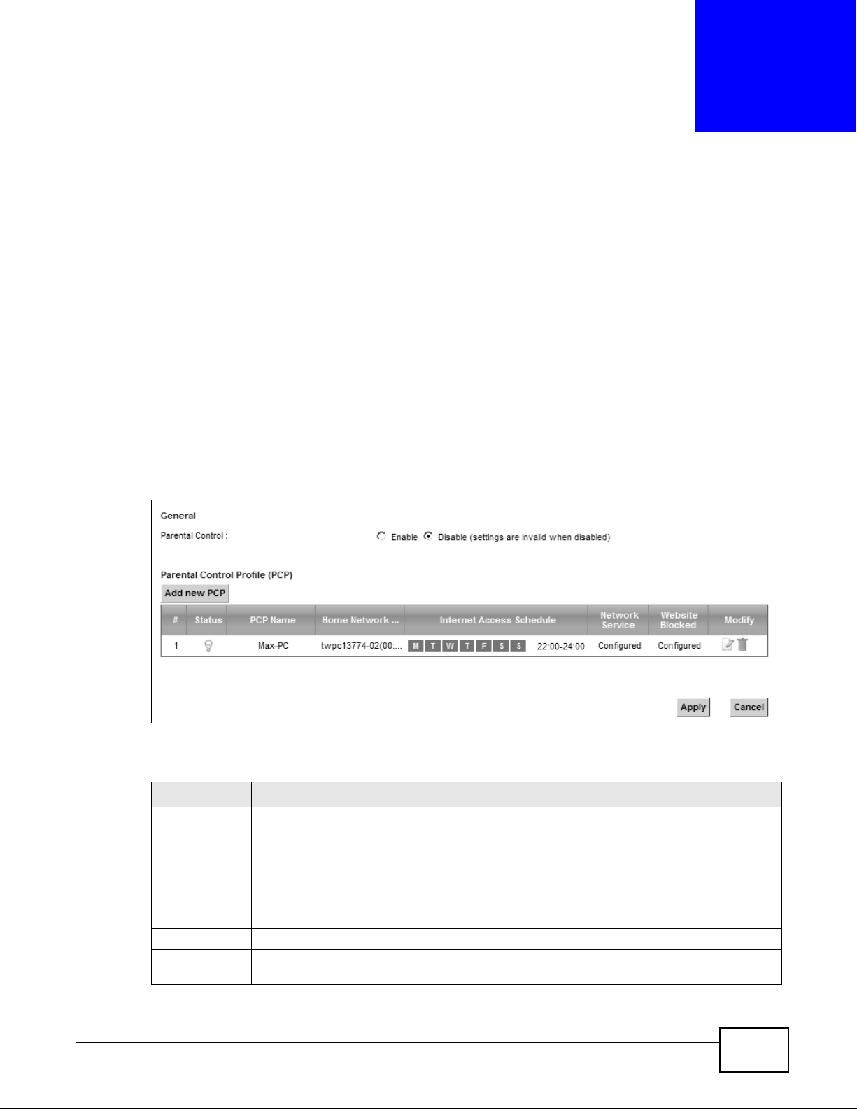
Use this screen to enable parental control, view the parental control rules and schedules.
Click Security > Parental Control to open the following screen.
Figure 124 Security > Parental Control
Parental Control
The following table describes the fields in this screen.
Table 93 Security > Parental Control
LABEL DESCRIPTION
Parental
Control
Add new PCP Click this if you want to configure a new parental control rule.
# This shows the index number of the rule.
Status This indicates whether the rule is active or not.
PCP Name This shows the name of the rule.
Home Network
User (MAC)
VMG8324-B10A / VMG8324-B30A Series User’s Guide 207
Select Enable to activate parental control.
A yellow bulb signifies that this rule is activ e. A gra y bulb signifies that this rule is not acti ve.
This shows the MAC address of the LAN user’s computer to which this rule applies.
Chapter 17 Parental Control
Table 93 Security > Parental Control (continued)
LABEL DESCRIPTION
Internet Access
Schedule
Network
Service
Website Block This shows whether the website block is configured. If not, None will be shown.
Modify Click the Edit icon to go to the screen where you can edit the rule.
Apply Click Apply to save your changes.
Cancel Click Cancel to restore your previously saved settings.
This shows the day(s) and time on which parental control is enabled.
This shows whether the network service is configured. If not, None will be shown.
Click the Delete icon to delete an existing rule.
17.2.1 Add/Edit a Parental Control Rule
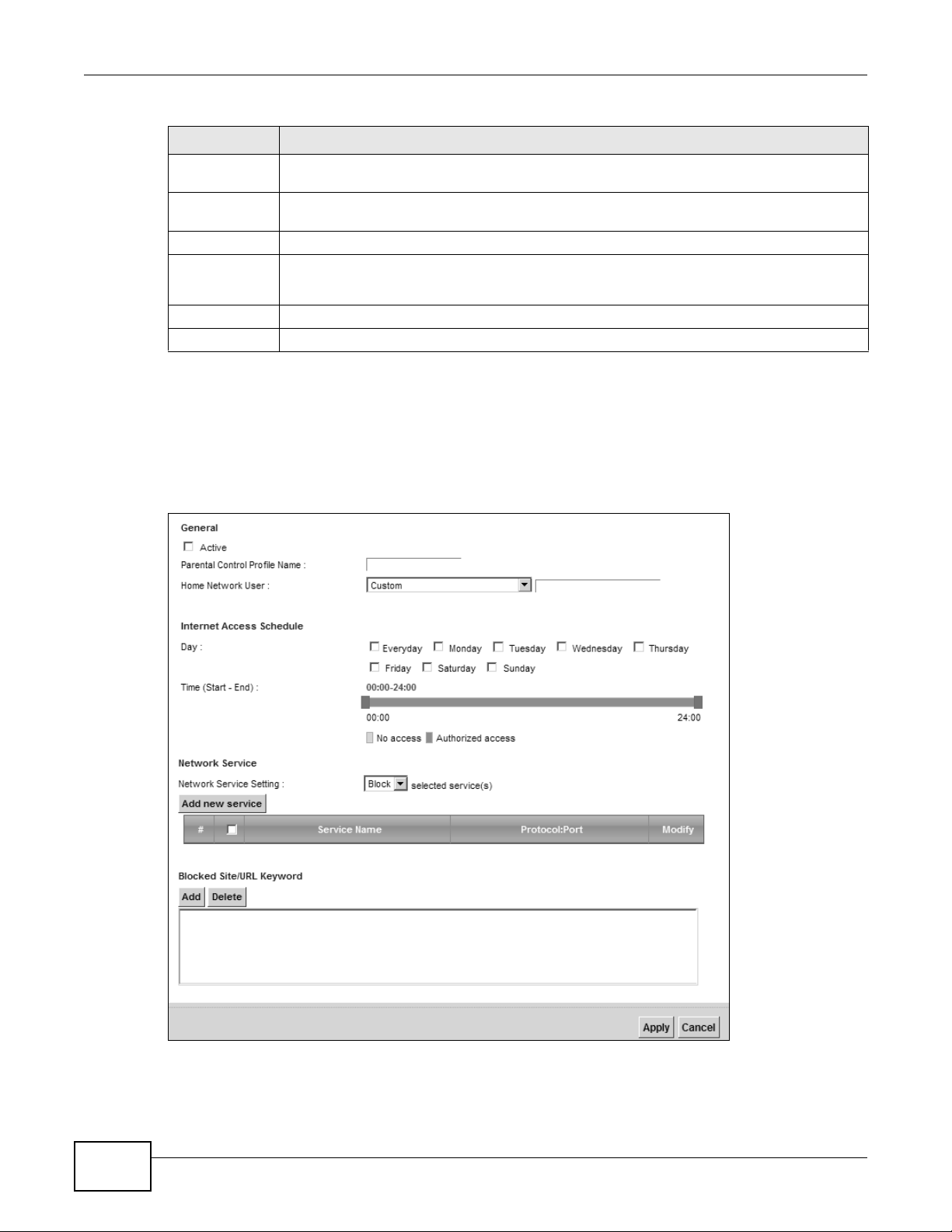
Click Add new PCP in the Parental Control screen to add a new rule or click the Edit icon next to
an existing rule to edit it. Use this screen to configure a restricted access schedule and/or URL
filtering settings to block the users on your network from accessing certain web sites.
Figure 125 Parental Control Rule: Add/Edit
208
VMG8324-B10A / VMG8324-B30A Series User’s Guide
Chapter 17 Parental Control
The following table describes the fields in this screen.
Table 94 Parental Control Rule: Add/Edit
LABEL DESCRIPTION
General
Active Select the checkbox to activate this parental control rule.
Parental
Control Profile
Name
Home Network
User
Internet Access Schedule
Day Select check boxes for the days that you want the Device to perform parental control.
Time Drag the time bar to define the time that the LAN user is allowed access.
Network Service
Network
Service Setting
Add new
service
# This shows the index number of the rule. Select the checkbox next to the rule to activate it.
Service Name This shows the name of the rule.
Protocol:Port This shows the protocol and the port of the rule.
Modify Click the Edit icon to go to the screen where you can edit the rule.
Enter a descriptive name for the rule.
Select the LAN user that you want to apply this rule to from the drop-down list box. If you
select Custom, enter the LAN user’s MAC address. If you select All, the rule applies to all
LAN users.
If you select Block, the Device prohibits the users from viewing the Web sites with the URLs
listed below.
If you select Allow, the Device blocks access to all URLs except ones listed below.
Click this to show a screen in which you can add a new service rule. You can configure the
Service Name, Protocol, and Name of the new rule.
Click the Delete icon to delete an existing rule.
Blocked Site/
URL Keyword
Apply Click this button to save your settings back to the Device.
Cancel Click Cancel to restore your previously saved settings.
Click Add to show a screen to enter the URL of web site or URL keyword to which the Device
blocks access. Click Delete to remove it.
VMG8324-B10A / VMG8324-B30A Series User’s Guide
209

Chapter 17 Parental Control
210
VMG8324-B10A / VMG8324-B30A Series User’s Guide

CHAPTER 18
18.1 Overview
You can define time periods and days during which the Device performs scheduled rules of certain
features (such as Firewall Access Control) in the Scheduler Rule screen.
18.2 The Scheduler Rule Screen
Use this screen to view, add, or edit time schedule rules.
Click Security > Scheduler Rule to open the following screen.
Figure 126 Security > Scheduler Rule
Scheduler Rule
The following table describes the fields in this screen.
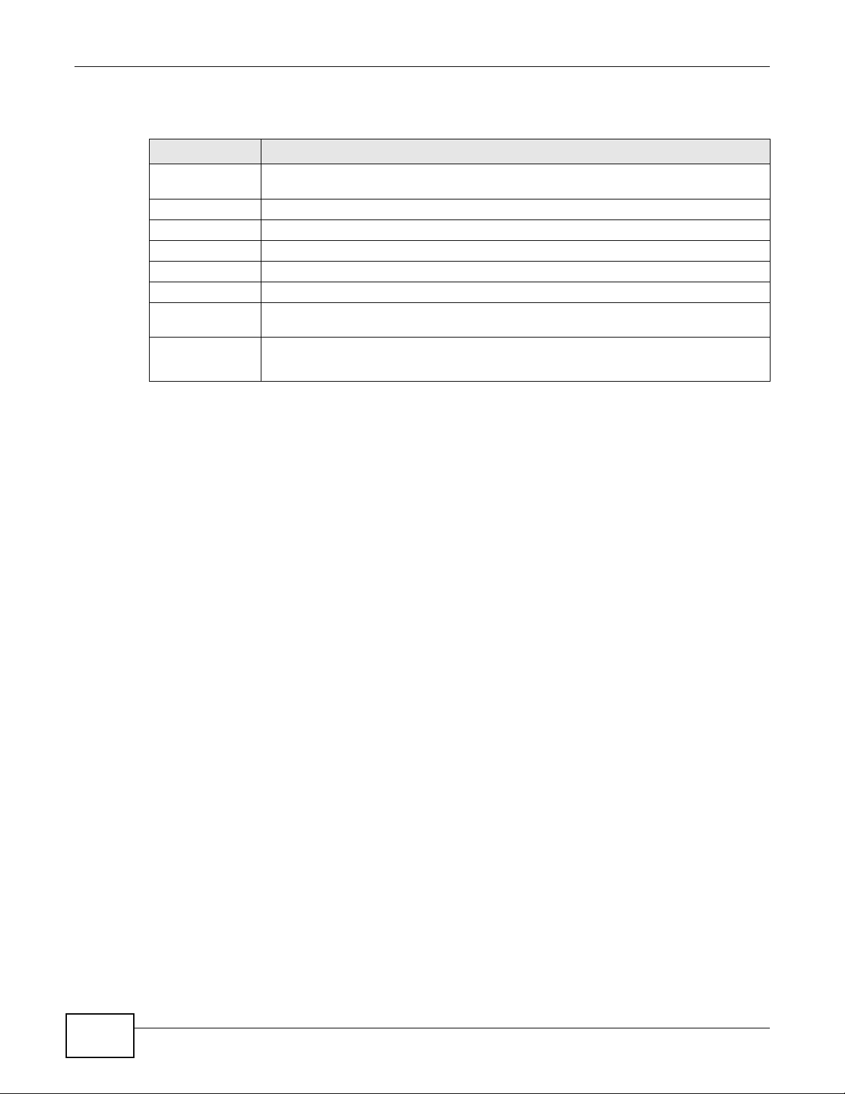
Table 95 Security > Scheduler Rule
LABEL DESCRIPTION
Add new rule Click this to create a new rule.
# This is the inde x num ber of the entry.
Rule Name This shows the name of the rule.
Day This shows the day(s) on which this rule is enabled.
Time This shows the period of time on which this rule is enabled.
Description This shows the description of this rule.
Modify Click the Edit icon to edit the schedule.
Click the Delete icon to delete a scheduler rule.
Note: You cannot delete a scheduler rule once it is applied to a certain feature.
VMG8324-B10A / VMG8324-B30A Series User’s Guide 211
Chapter 18 Scheduler Rule
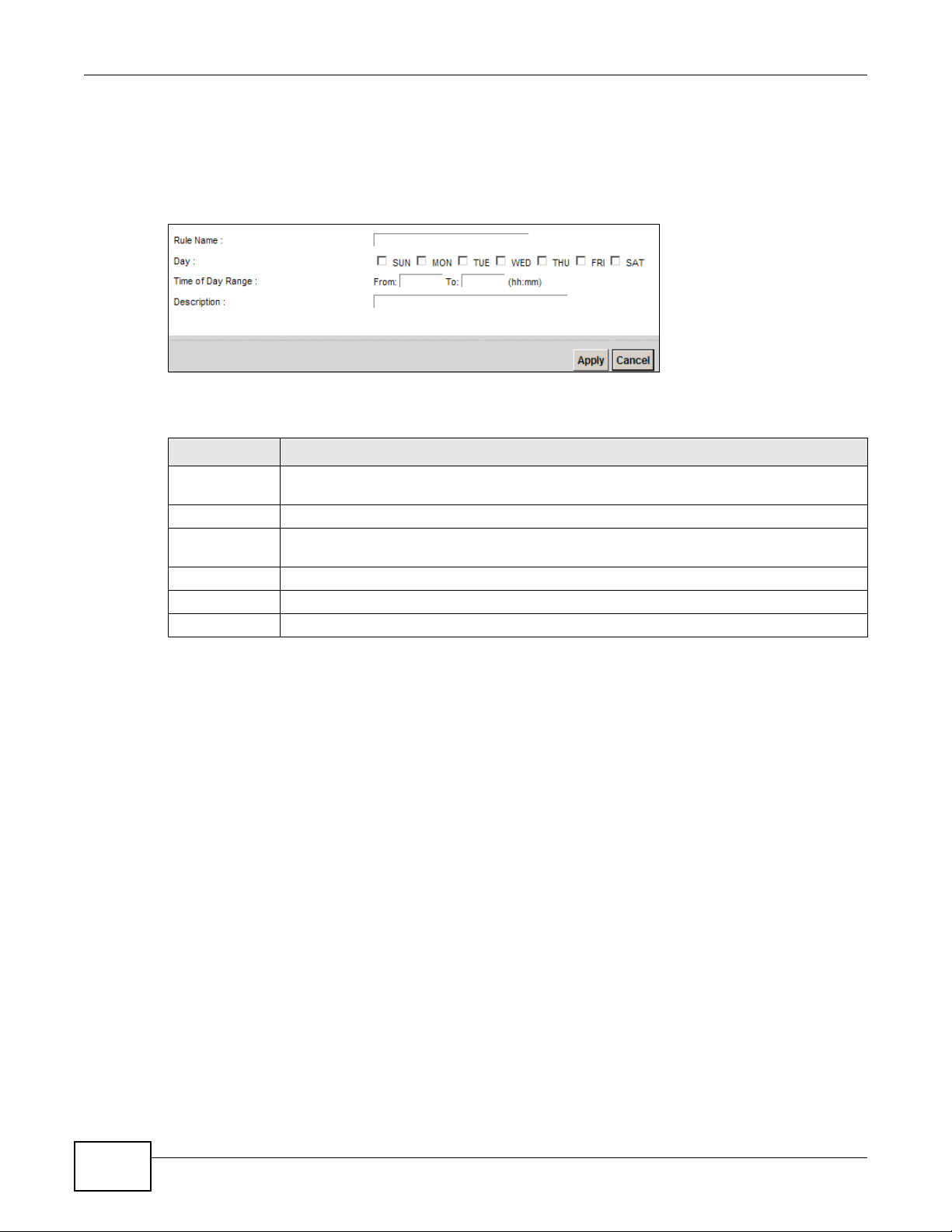
18.2.1 Add/Edit a Schedule
Click the Add button in the Scheduler Rule screen or click the Edit icon next to a schedule rule to
open the following screen. Use this screen to configure a restricted access schedule.
Figure 127 Scheduler Rule: Add/Edit
The following table describes the fields in this screen.
Table 96 Scheduler Rule: Add/Edit
LABEL DESCRIPTION
Rule Name Enter a name (up to 31 printable English keyboard characters, not including spaces) for this
schedule.
Day Select check boxes for the days that you want the Device to perform this scheduler rule.
Time if Day
Range
Description Enter a description for this scheduler rule.
Apply Click Apply to save your changes.
Cancel Click Cancel to exit thi s screen without saving.
Enter the time period of each day, in 24-hour format, during which the rule will be enfo rced.
212
VMG8324-B10A / VMG8324-B30A Series User’s Guide

CHAPTER 19
19.1 Overview
The Device can use certificates (also called digital IDs) to authenticate users. Certificates are based
on public-private key pairs. A certificate contains the certificate owner’s identity and public key.
Certificates provide a way to exchange public keys for use in authentication.
19.1.1 What You Can Do in this Chapter
•The Local Certificates screen lets you generate certification requests and import the Device's
CA-signed certificates (Section 19.4 on page 216).
•The Trusted CA screen lets you save the certificates of trusted CAs to the Device (Section 19.4
on page 216).
Certificates
19.2 What You Need to Know
The following terms and concepts may help as you read through this chapter.
Certification Authority
A Certification Authority (CA) issues certificates and guarantees the identity of each certificate
owner. There are commercial certification authorities like CyberTrust or VeriSign and government
certification authorities. The certification authority uses its private key to sign certificates. Anyone
can then use the certification authority's public key to v erify the certificates. Y ou can use the Device
to generate certification requests that contain identifying information and public keys and then send
the certification requests to a certification authority.
19.3 The Local Certificates Screen
Click Security > Certificates to open the Local Certificates screen. This is the Device’ s summary
list of certificates and certification requests.
Figure 128 Security > Certificates > Local Certificates
VMG8324-B10A / VMG8324-B30A Series User’s Guide 213
Chapter 19 Certificates
The following table describes the labels in this screen.
Table 97 Security > Certificates > Local Certificates
LABEL DESCRIPTION
Private Key is
protected by a
password
Browse... Click this to find the certificate file you want to upload.
Import Certificate Click this button to save the certificate that you have enrolled from a certification
Create Certificate
Request
Current File This field displays the name used to identify this certificate. It is recommended that you
Subject This field displays identifying information about the certificate’s owner, such as CN
Issuer This field displays identifying information about the certificate’s issuing certification
Valid From This field displays the date that the certificate becomes applicable. The text displays in
Valid To This field displays the date that the certificate expires. The text displays in red and
Modify Click the View icon to open a screen with an in-depth list of information about the
Select the checkbox and enter the private key into the text box to store it on the Device.
The private key should not exceed 63 ASCII characters (not including spaces).
authority from your computer to the Device.
Click this button to go to the screen where you can have the Device generate a
certification request.
give each certificate a unique name.
(Common Name), OU (Organizational Unit or department), O (Organization or company)
and C (Country). It is recommended that each certificate have unique subject
information.
authority, such as a common name, organizational unit or department, organization or
company and country.
red and includes a Not Yet Valid! message if the certificate has not yet become
applicable.
includes an Expiring! or Expired! message if the certificate is about to expire or has
already expired.
certificate (or certification request).
For a certification request, click Load Signed to import the signed certificate.
Click the Remove icon to delete the certificate (or certificatio n request). You cannot
delete a certificate that one or more features is configured to use.
19.3.1 Create Certificate Request
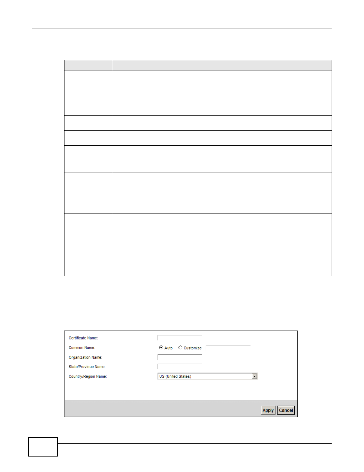
Click Security > Certificates > Local Certificates and then Create Certificate Request to
open the following screen. Use this screen to have the Device generate a certification request.
Figure 129 Create Certificate Request
214
VMG8324-B10A / VMG8324-B30A Series User’s Guide
Chapter 19 Certificates
The following table describes the labels in this screen.
Table 98 Create Certificate Request
LABEL DESCRIPTION
Certificate
Name
Common Name Select Auto to have the Device configure this field automatically. Or select Customize to
Organization
Name
State/Province
Name
Country/Region
Name
Apply Click Apply to save your changes.
Cancel Click Cancel to exit this screen without saving.
Type up to 63 ASCII characters (not including spaces) to identify this certificate.
enter it manually.
Type the IP address (in dotted decimal notation), domain name or e-mail address in the
field provided. The domain name or e-mail address can be up to 63 ASCII characters. The
domain name or e-mail address is for identification purposes only and can be any string.
Type up to 63 characters to identify the company or group to which the certificate owner
belongs. You may use any character, including spaces, but the Device drops trailing spac es.
Type up to 32 characters to identify the state or province where the certificate owner is
located. You may use any character, including spaces, but the Device drops trailing spaces.
Select a country to identify the nation where the certificate owner is located.
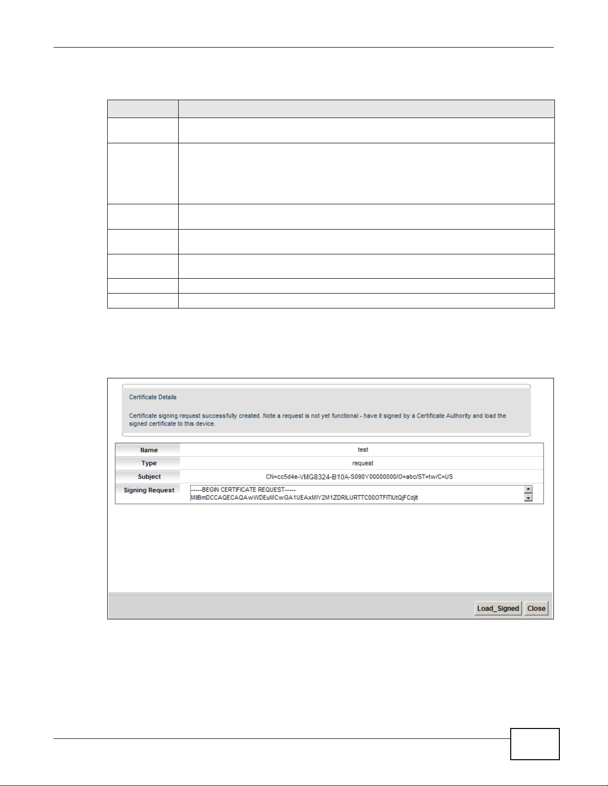
After you click Apply, the following screen displays to notify you that you need to get the certificate
request signed by a Certificate Authority. If you already have, click Load_Signed to import the
signed certificate into the Device. Otherwise click Back to return to the Local Certificates screen.
Figure 130 Certificate Request Created
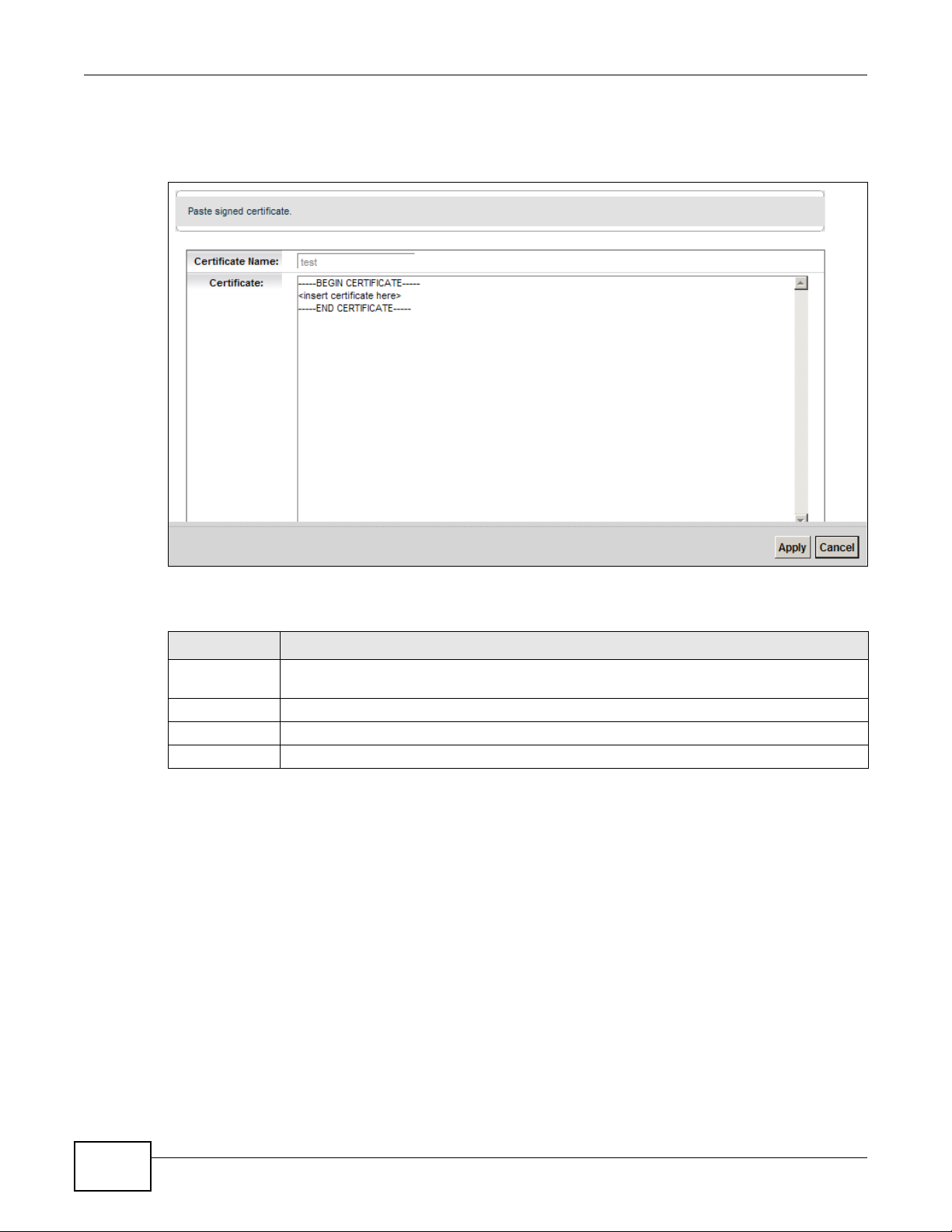
19.3.2 Load Signed Certificate
After you create a certificate request and have it signed by a Certificate Authority, in the Local
Certificates screen click the certificate request’s Load Signed icon to import the signed certificate
into the Device.
VMG8324-B10A / VMG8324-B30A Series User’s Guide
215
Chapter 19 Certificates
Note: You must remove any spaces from the certificate’s filename before you can import
it.
Figure 131 Load Signed Certificate
The following table describes the labels in this screen.
Table 99 Load Signed Certificate
LABEL DESCRIPTION
Certificate
Name
Certificate Copy and paste the signed certificate into the text box to store it on the Device.
Apply Click Apply to save your changes.
Cancel Click Cancel to exit this screen without saving.
This is the name of the signed cert ificate.
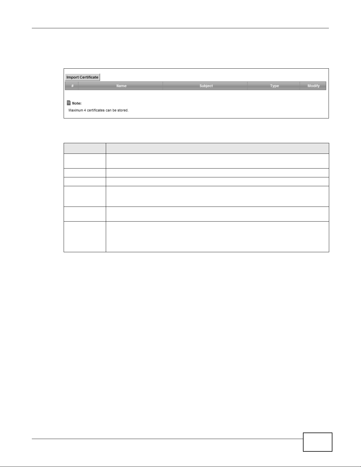
19.4 The Trusted CA Screen
Click Security > Certificates > Trusted CA to open the following screen. This screen displays a
summary list of certificates of the certification authorities that you have set the Device to accept as
trusted. The Device accepts any valid certificate signed by a certification authority on this list as
216
VMG8324-B10A / VMG8324-B30A Series User’s Guide
Chapter 19 Certificates
being trustworthy; thus you do not need to import any certificate that is signed by one of these
certification authorities.
Figure 132 Security > Certificates > Trusted CA
The following table describes the fields in this screen.
Table 100 Security > Certificates > Trusted CA
LABEL DESCRIPTION
Import
Certificate
# This is the index number of the entry.
Name This field displays the name used to identify this certificate.
Subject This field displays information that identifies the owner of the certificate, such as Common
Type This field displays general information about the certificate. ca means that a Certification
Modify Click the View icon to open a screen with an in-depth list of information about the
Click this button to open a screen where you can save the certificate of a certification
authority that you trust to the Device.
Name (CN), OU (Organizational Unit or department), Organization (O), State (ST) and
Country (C). It is recommended that each certificate have unique subject information.
Authority signed the certificate.
certificate (or certification request).
Click the Remove button to delete the certificate (or certification request). You cannot
delete a certificate that one or more features is configured to use.
VMG8324-B10A / VMG8324-B30A Series User’s Guide
217
Chapter 19 Certificates
19.4.1 View Trusted CA Certificate
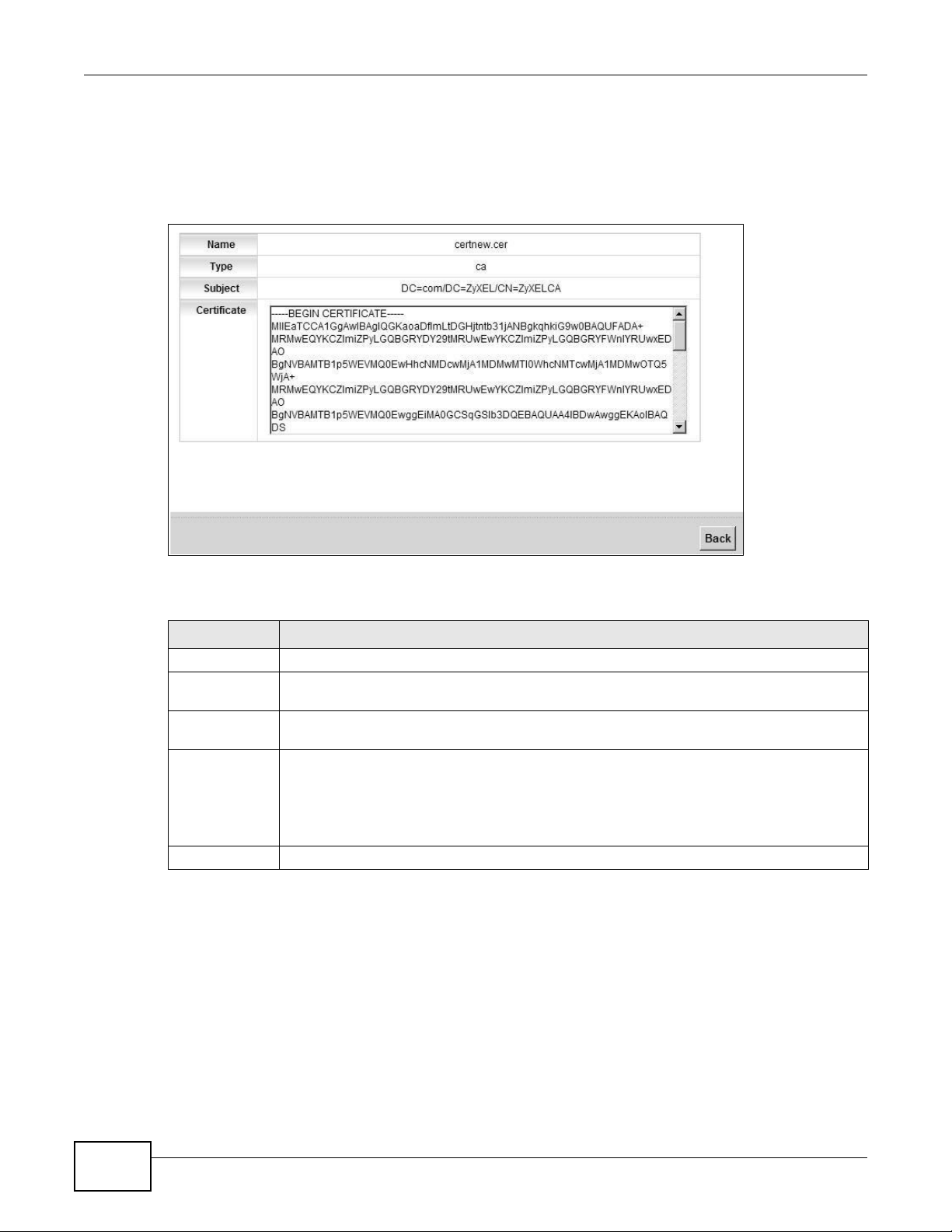
Click the View icon in the Trusted CA screen to open the following screen. Use this screen to view
in-depth information about the certification authority’s certificate.
Figure 133 Trusted CA: View
The following table describes the fields in this screen.
Table 101 Trusted CA: View
LABEL DESCRIPTION
Name This field displays the identifying name of this certificate.
Type This field displays general information about the certificate. ca means that a Certification
Authority signed the certificate.
Subject This field displays information that identifies the owner of the certificate, such as Common
Certificate This read-only text box displays the certificate in Privacy Enhanced Mail (PEM) format. PEM
Back Click Back to return to the previous screen.
Name (CN), Organizational Unit (OU), Organization (O) and Country (C).
uses base 64 to convert the binary certificate into a printable form.
You can cop y and past e the certific ate in to an e-ma il to se nd to fr iends or col lea gues or yo u
can copy and paste the certificate into a text editor and save the file on a management
computer for later distribution (via floppy disk for example).
218
VMG8324-B10A / VMG8324-B30A Series User’s Guide
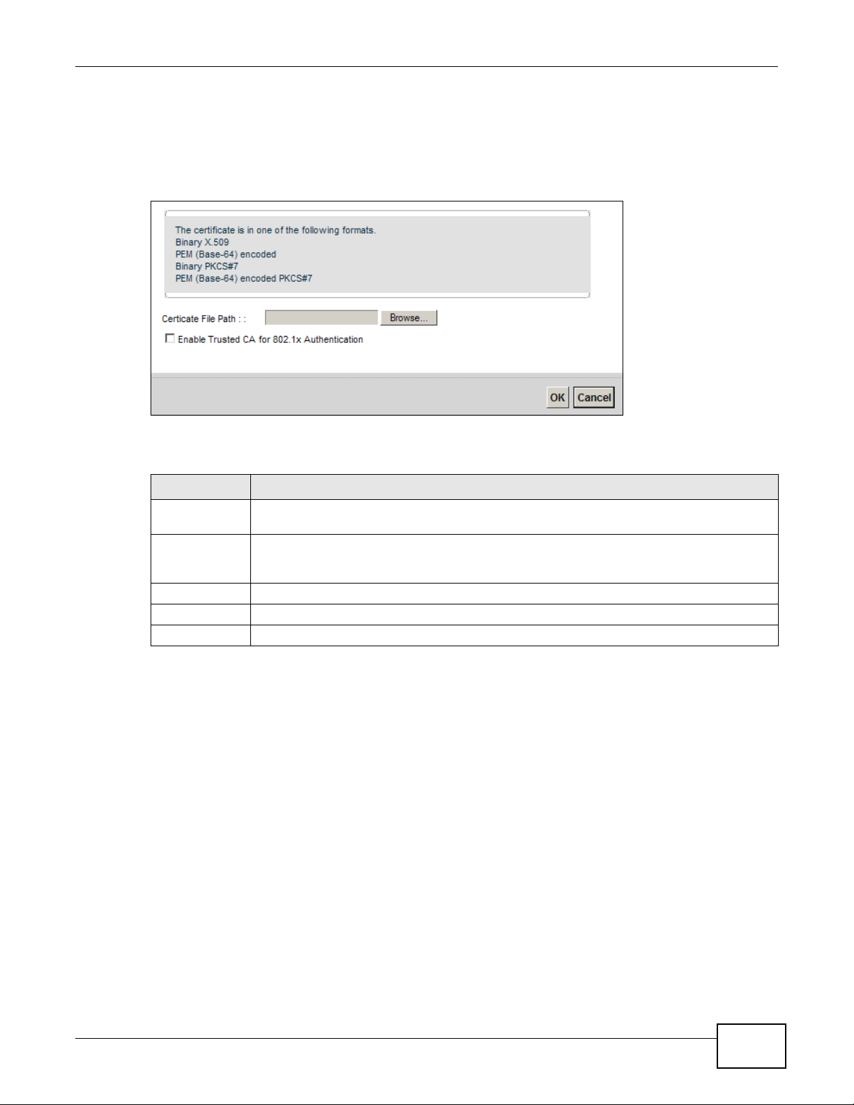
19.4.2 Import Trusted CA Certificate
Click the Import Certificate button in the Trusted CA screen to open the following screen. The
Device trusts any valid certificate signed by any of the imported trusted CA certificates.
Figure 134 Trusted CA: Import Certificate
The following table describes the fields in this screen.
Chapter 19 Certificates
Table 102 Trusted CA: Import Certificate
LABEL DESCRIPTION
Certificate File
Path
Enable Trusted
CA for 802.1x
Authentication
Certificate Copy and paste the certificate into the text box to store it on the Device.
OK Click OK to save your changes.
Cancel Click Cancel to exit this screen without saving.
Type in the location of the certificate you want to upload in this field or click Browse ... to
find it.
If you select this checkbox, the trusted CA will be used for 802.1x authentication. The
selected trusted CA will be displayed in the Network Setting > Broadband > 802.1x:
Edit screen.
VMG8324-B10A / VMG8324-B30A Series User’s Guide
219

Chapter 19 Certificates
220
VMG8324-B10A / VMG8324-B30A Series User’s Guide
CHAPTER 20
Local Network
Remote Network
VPN Tunnel
20.1 Overview
A virtual private network (VPN) provides secure communications over the the Internet. Internet
Protocol Security (IPSec) is a standards-based VPN that provides confidentiality , data integrity, and
authentication. This chapter shows you how to configure the Device’s VPN settings.
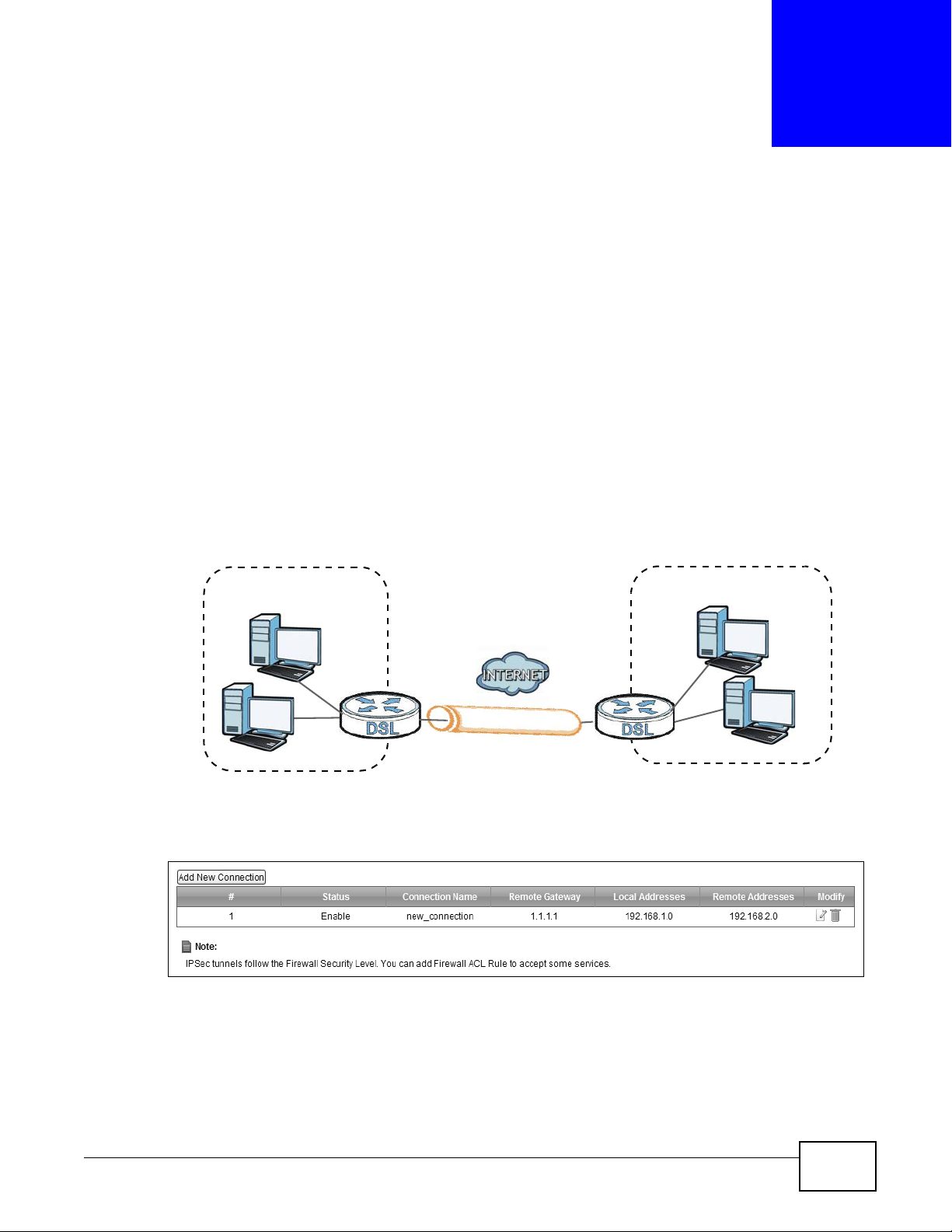
20.2 The IPSec VPN General Screen
Use this screen to view and manage your VPN tunnel policies. The following figure helps explain the
main fields in the web configurator.
Figure 135 IPSec Fields Summary
VPN
Click Security > IPSec VPN to open this screen as shown next.
Figure 136 Security > IPSec VPN
VMG8324-B10A / VMG8324-B30A Series User’s Guide 221
Chapter 20 VPN
This screen contains the following fields:
Table 103 Security > IPSec VPN
LABEL DESCRIPTION
Add New
Connection
# This displays the index number of an entry.
Status This displays whether the VPN policy is enabled (Enable) or not (Disable).
Connection Name The name of the VPN policy.
Remote Gateway This is the IP address of the remote IPSec router in the IKE SA.
Local Addresses This displays the IP address(es) on the LAN behind your Device.
Remote
Addresses
Delete Click the Edit icon to modify the VPN policy.
Click this button to add an item to the list.
This displays the IP address(es) on the LAN behind the remote IPSec’s router.
Click the Delete icon to delete the VPN policy.
20.3 The IPSec VPN Add/Edit Screen
Use these settings to add or edit VPN policies. Click the Add New Connection button in the
Security > VPN screen to open this screen as shown next.
222
VMG8324-B10A / VMG8324-B30A Series User’s Guide
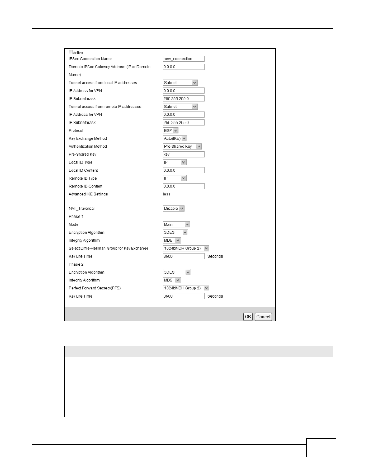
Figure 137 Security > IPSec VPN: Add/Edit
Chapter 20 VPN
This screen contains the following fields:
Table 104 Security > IPSec VPN: Add/Edit
LABEL DESCRIPTION
Active Select this to activate this VPN policy.
IPSec Connection
Name
Remote IPSec
Gateway Address
T unnel access
from local IP
addresses
Enter the name of the VPN policy.
Enter the IP address of the remote IPSec router in the IKE SA.
Select Single Address to have only one local LAN IP address use the VPN tunnel. Select
Subnet to specify local LAN IP addresses by their subnet mask.
VMG8324-B10A / VMG8324-B30A Series User’s Guide
223
Chapter 20 VPN
Table 104 Security > IPSec VPN: Add/Edit
LABEL DESCRIPTION
IP Address for
VPN
IP Subnetmask If Subnet is selected, enter the subnet mask to identify the network address.
T unnel access
from remote IP
addresses
IP Address for
VPN
IP Subnetmask If Subnet is selected, enter the subnet mask to identify the network address.
Protocol Select which protocol you want to use in the IPSec SA. Choices are:
If Single Address is selected, enter a (static) IP address on the LAN behind your Device.
If Subnet is selected, specify IP addresses on a network by their subne t mask by entering
a (static) IP address on the LAN behind your Device. Then enter the subnet mask to
identify the network address.
Select Single Address to have only one remote LAN IP address use the VPN tunnel.
Select Subnet to specify remote LAN IP addresses by their subnet mask.
If Single Address is selected, enter a (static) IP address on the LAN behind the remote
IPSec’s router.
If Subnet is selected, specify IP addresses on a network by their subne t mask by entering
a (static) IP address on the LAN behind the remote IPSec’s router. Then enter the subnet
mask to identify the network address.
AH (RFC 2402) - provides integrity, authentication, sequence integrity (replay
resistance), and non-repudiation but not encryption. If you select AH, you must select an
Integraty Algorithm.
ESP (RFC 2406) - provides encryption and the same services offered by AH, but its
authentication is weaker. If you select ESP, you must select an Encryption Agorithm
and Integraty Algorithm.
Both AH and ESP increase processing requirements and latency (delay). The Device and
remote IPSec router must use the same active protocol.
Key Exchange
Method
Select the key exchange method:
Auto(IKE) - Select this to use automatic IKE key management VPN connection policy.
Manual - Select this option to configure a VPN connection policy that uses a manual key
instead of IKE key management. This may be useful if you have problems with IKE key
management.
Note: Only use manual key as a temporary solution, because it is not as secure as a regular
IPSec SA.
Authentication
Method
Pre-Shared Key Type your pre-shared key in this fiel d. A pre -s h ar ed key identifies a communicating party
Local ID Type Select IP to identify the Device by its IP address.
Select Pre-Shared Key to use a pre-shared key for authentication, and type in your pre-
shared key. A pre-shared key identifies a communicating party during a phase 1 IKE
negotiation. It is called "pre-shared" because you have to share it with another party
before you can communicate with them over a secure connection.
Select Certificate (X.509) to use a certificate for authentication.
during a phase 1 IKE negotiation.
Type from 8 to 31 case-sensitive ASCII characters or from 16 to 62 hexadecimal ("0-9",
"A-F") characters. You must precede a hexadecimal key with a "0x” (zero x), which is not
counted as part of the 16 to 62 character range for the key. For example, in
"0x0123456789ABCDEF", “0x” denotes that the key is hexadecimal and
“0123456789ABCDEF” is the key itself.
224
Select E-mail to identify this Device by an e-mail address.
Select DNS to identify this Device by a domain name.
Select ASN1DN (Abstract Syntax Notation one - Distinguished Name) to this Device by
the subject field in a certificate. This is used only with certificate-based authentication.
VMG8324-B10A / VMG8324-B30A Series User’s Guide
Chapter 20 VPN
Table 104 Security > IPSec VPN: Add/Edit
LABEL DESCRIPTION
Local ID Content When you select IP in the Local ID Type field, type the IP address of your computer in
this field. If you configure this field to 0.0.0.0 or leave it blank, the Device automatically
uses the Pre-Shared Key (refer to the Pre-Shared Key field description).
It is recommended that you type an IP address other than 0.0.0.0 in this field or use the
DNS or E-mail type in the following situations.
• When there is a NAT router between the two IPSec routers.
• When you want th e remote IPSec router to be able to distinguish between VPN
connection requests that come in from IPSec route rs with dynami c W AN IP addresses .
When you select DNS or E-mail in the Local ID Type field, type a domain name or email address by which to identify this Device in this field. Use up to 31 ASCII characters
including spaces, although trailing spaces are truncated. The domain name or e-mail
address is for identification purposes only and can be any string.
Remote ID Type Select IP to identify the remote IPSec router by its IP address.
Select E-mail to identify the remote IPSec router by an e-mail address.
Select DNS to identify the remote IPSec router by a domain name.
Select ASN1DN to identify the remote IPSec router by the subject field in a certificate.
This is used only with certificate-based authentication.
Remote ID
Content
The configuration of the remote content depends on the remote ID type.
For IP, type the IP address of the computer with which you will make the VPN connection.
If you configure this field to 0.0.0.0 or leave it blank, the Device will use the address in
the Remote IPSec Gateway Address field (refer to the Remote IPSec Gateway
Address field description).
For DNS or E-mail, type a domain name or e-mail address by which to identify the
remote IPSec router. Use up to 31 ASCII characters including spaces, although trailing
spaces are truncated. The domain name or e-mail address is for identification purposes
only and can be any string.
It is recommended that you type an IP address other than 0.0.0.0 or use the DNS or E-
mail ID type in the following situations:
• When there is a NAT router between the two IPSec routers.
• When you want the Device to distinguish between VPN connection requests that come
in from remote IPSec routers with dynamic WAN IP addresses.
Advanced IKE
Settings
NAT_Traversal Select Enable
Phase 1
Mode Select the negotiation mode to use to negotiate the IKE SA. Choices are:
Click more to display advanced settings. Click less to display basic settings only.
vic
e and remote IPSec router . The remote IPSec router must also enable NAT tr aversal,
De
and the NAT routers have to forward UDP port 500 packets to the remote IPSec router
behind the NAT router. Otherwise, select Disable.
Main - this encrypts the Device’s and remote IPSec router’s identities but takes more
time to establish the IKE SA.
Aggressive - this is faster but does not encrypt the identities.
The Device and the remote IPSec router must use the same negotiation mode.
if you want to set up a VPN tunnel when th ere are NA T routers betwe en the
VMG8324-B10A / VMG8324-B30A Series User’s Guide
225
Chapter 20 VPN
Table 104 Security > IPSec VPN: Add/Edit
LABEL DESCRIPTION
Encryption
Algorithm
Integrity
Algorithm
Select DiffieHellman Group
for Key Exchange
Key Life Time Define the length of time before an IPSec SA automatically renegotiates in this field.
Select which key size and encryption algorithm to use in the IKE SA. Choices are:
DES - a 56-bit key with the DES encryption algorithm
3DES - a 168-bit key with the DES encryption algo rithm
AES - 128 - a 128-bit key with the AES encryption algorithm
AES - 196 - a 196-bit key with the AES encryption algorithm
AES - 256 - a 256-bit key with the AES encryption algorithm
The Device and the remote IPSec router must use the same key size and encryption
algorithm. Longer keys require more processing power, resulting in increased latency and
decreased throughput.
Select which hash algorithm to use to authenticate packet data. Choices are MD5, SHA1.
SHA is generally considered stronger than MD5, but it is also slower.
Select which Diffie-Hellman key group you want to use for encryption keys. Choices for
number of bits in the random number are: 768, 1024, 1536, 2048, 3072, 4096.
The longer the key, the more secure the encryption, but also the long er it takes to encrypt
and decrypt information. Both routers must use the same DH key group.
Phase 2
Encryption
Algorithm
Integrity
Algorithm
A short SA Life Time increases security by forcing the two VPN gateways to update the
encryption and authentication keys. However, every time the VPN tunnel renegotiates, all
users accessing remote resources are temporarily disconnected.
Select which key size and encryption algorithm to use in the IKE SA. Choices are:
DES - a 56-bit key with the DES encryption algorithm
3DES - a 168-bit key with the DES encryption algo rithm
AES - 128 - a 128-bit key with the AES encryption algorithm
AES - 192 - a 196-bit key with the AES encryption algorithm
AES - 256 - a 256-bit key with the AES encryption algorithm
Select ESP_NULL to set up a tunnel without encryption. When you select ESP_NULL,
you do not enter an encryption key.
The Device and the remote IPSec router must use the same key size and encryption
algorithm. Longer keys require more processing power, resulting in increased latency and
decreased throughput.
Select which hash algorithm to use to authenticate packet data. Choices are MD5 and
SHA1. SHA is generally considered stronger than MD5, but it is also slower.
226
VMG8324-B10A / VMG8324-B30A Series User’s Guide
Chapter 20 VPN
Table 104 Security > IPSec VPN: Add/Edit
LABEL DESCRIPTION
Perfect Forward
Secrecy (PFS)
Key Life Time Define the length of time before an IPSec SA automatically renegotiates in this field.
The following fields are available if you select Manual in the Key Exchange Method field.
Encryption
Algorithm
Encryption
Key
Authentication
Algorithm
Authentication
Key
Select whether or not you want to enable Perfect Forward Secrecy (PFS)
PFS changes the root key that is used to generate encryption keys for each IPSec SA. The
longer the key, the more secure the encryption, but also the longer it takes t o encrypt and
decrypt information. Both routers must use the same DH key group. Choices are:
None - do not use any random number.
768bit(DH Group1) - use a 768-bit random number
1024bit(DH Group2) - use a 1024-bit random number
1536bit(DH Group5) - use a 1536-bit random number
2048bit(DH Group14) - use a 2048-bit random number
3072bit(DH Group15) - use a 3072-bit random number
4096bit(DH Group16) - use a 4096-bit random number
A short SA Life Time increases security by forcing the two VPN gateways to update the
encryption and authentication keys. However, every time the VPN tunnel renegotiates, all
users accessing remote resources are temporarily disconnected.
Select which key size and encryption algorithm to use in the IKE SA. Choices are:
DES - a 56-bit key with the DES encryption algorithm
3DES - a 168-bit key with the DES encryption algo rithm
EPS_NULL - no encryption key or algorithm
This field is applicable when you select an Encryption Algorithm.
Enter the encryption key, which depends on the encryption algorithm.
DES - type a unique key 16 hexadecimal characters long
3DES - type a unique key 48 hexadecimal characters long
Select which hash algorithm to use to authenticate packet data. Choices are MD5, SHA1.
SHA is generally considered stronger than MD5, but it is also slower.
Enter the authentication key, which depends on the authentication algorithm.
MD5 - type a unique key 32 hexadecimal characters long
SHA1 - type a unique key 40 hexadecimal characters long
SPI Type a unique SPI (Security Parameter Index) in hexadecimal characters.
The SPI is used to identify the Device during authentication.
The Device and remote IPSec router must use the same SPI.
OK Click OK to save your changes.
Cancel Click Cancel to restore your previously saved settings.
VMG8324-B10A / VMG8324-B30A Series User’s Guide
227
Chapter 20 VPN
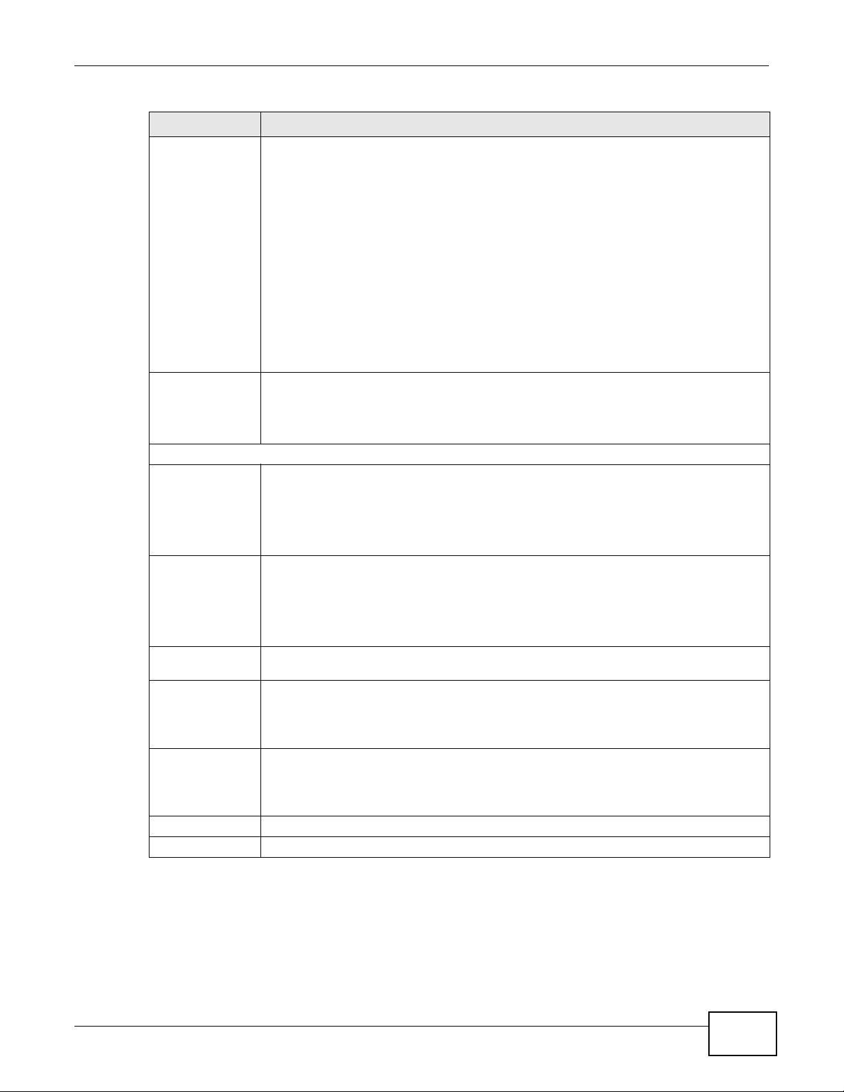
20.4 The IPSec VPN Monitor Screen
Use this screen to check your VPN tunnel’s current status. You can also manually trigger a VPN
tunnel to the remote network. Click Security > IPSec VPN > Monitor to open this screen as
shown next.
Figure 138 Security > IPSec VPN > Monitor
This screen contains the following fields:
Table 105 Security > IPSec VPN > Monitor
LABEL DESCRIPTION
Refresh Interval Select how often you want the Device to update this screen. Select No Refresh to have
the Device stop updating the screen.
Status This displays a green line between two hosts if the VPN tunnel has been established
Connection Name This displays the name of the VPN policy.
Remote Gateway This is the IP address of the remote IPSec router in the IKE SA.
Local Addresses This displays the IP address(es) on the LAN behind your Device.
Remote
Addresses
Action Click Trigger to establish a VPN connection with the remote network.
successfully. Otherwise, it displays a red line in between.
This displays the IP address(es) on the LAN behind the remote IPSec router.
20.5 Technical Reference
This section provides some technical background information about the topics covered in this
section.
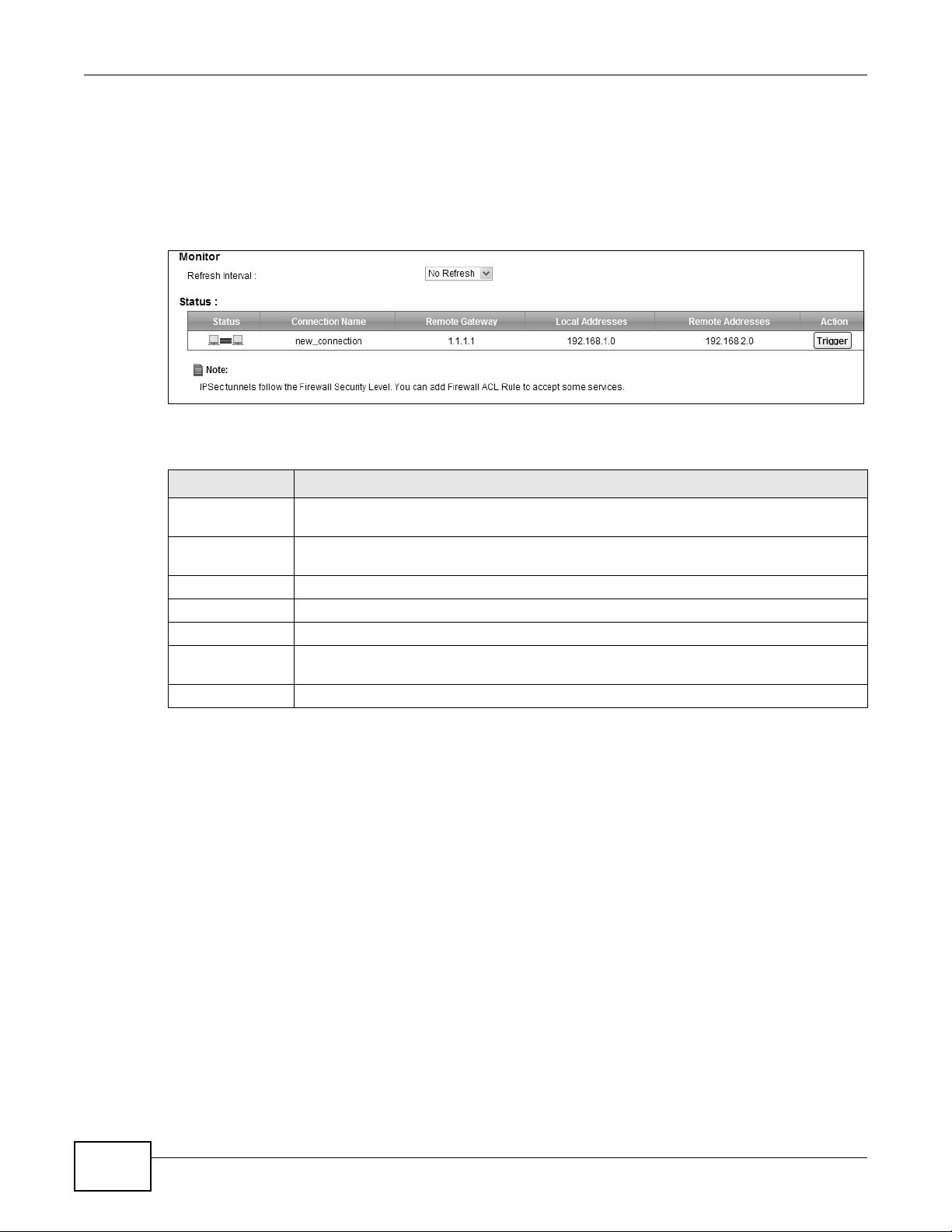
20.5.1 IPSec Architecture
The overall IPSec architecture is shown as follows.
228
VMG8324-B10A / VMG8324-B30A Series User’s Guide
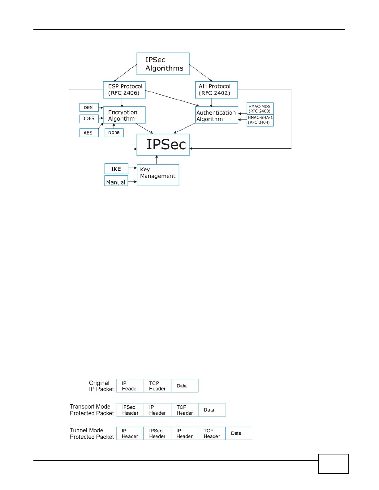
Figure 139 IPSec Architecture
IPSec Algorithms
Chapter 20 VPN
The ESP (Encapsulating Security Payload) Protocol (RFC 2406) and AH (Authentication Header)
protocol (RFC 2402) describe the packet formats and the default standards for packet structure
(including implementation algorithms).
The Encryption Algorithm describes the use of encryption techniques such as DES (Data Encryption
Standard) and Triple DES algorithms.
The Authentication Algorithms, HMAC-MD5 (RFC 2403) and HMAC-SHA-1 (RFC 2404, provide an
authentication mechanism for the AH and ESP protocols.
Key Management
Key management allows you to determine whether to use IKE (ISAKMP) or manual key
configuration in order to set up a VPN.
20.5.2 Encapsulation
The two modes of operation for IPSec VPNs are Transport mode and Tunnel mode. A t the time of
writing, the Device supports Tunnel mode only.
Figure 140 Transport and Tunnel Mode IPSec Encapsulation
VMG8324-B10A / VMG8324-B30A Series User’s Guide
229

Chapter 20 VPN
T ransport Mode
Transport mode is used to protect upper layer protocols and only affects the data in the IP packet.
In Transport mode, the IP packet contains the security protocol (AH or ESP) located after the
original IP header and options, but before any upper layer protocols contained in the packet (such
as TCP and UDP).
With ESP, protection is applied only to the upper layer protocols contained in the packet. The IP
header information and options are not used in the authentication process. Therefore, the
originating IP address cannot be verified for integrity against the data.
With the use of AH as the security protocol, protection is extended forward into the IP header to
verify the integrity of the entire packet by use of portions of the original IP header in the hashing
process.
Tunnel Mode
Tunnel mode encapsulates the entire IP packet to transmit it securely. A Tunnel mode is required
for gateway services to provide access to internal systems. Tunnel mode is fundamentally an IP
tunnel with authentication and encryption. This is the most common mode of operation. Tunnel
mode is required for gateway to gateway and host to gateway communications. Tunnel mode
communications have two sets of IP headers:
• Outside header: The outside IP header contains the destination IP address of the VPN gateway.
• Inside header: The inside IP header contains the destination IP address of the final system
behind the VPN gateway. The security protocol appears after the outer IP header and before the
inside IP header.
20.5.3 IKE Phases
There are two phases to every IKE (Internet Key Exchange) negotiation – phase 1 (Authentication)
and phase 2 (Key Exchange). A phase 1 exchange establishes an IKE SA and the second one uses
that SA to negotiate SAs for IPSec.
230
VMG8324-B10A / VMG8324-B30A Series User’s Guide
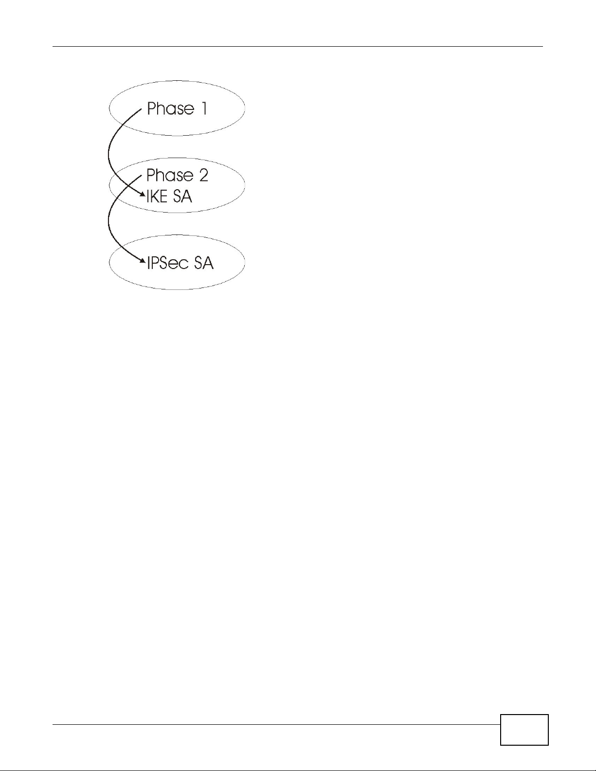
Figure 141 Two Phases to Set Up the IPSec SA
In phase 1 you must:
Chapter 20 VPN
• Choose a negotiation mode.
• Authenticate the connection by entering a pre-shared key.
• Choose an encryption algorithm.
• Choose an authentication algorithm.
• Choose a Diffie-Hellman public-key cryptography key group.
• Set the IKE SA lifetime. This field allows you to determine how long an IKE SA should stay up
before it times out. An IKE SA times out when the IKE SA lifetime period expires. If an IKE SA
times out when an IPSec SA is already established, the IPSec SA stays connected.
In phase 2 you must:
• Choose an encryption algorithm.
• Choose an authentication algorithm
• Choose a Diffie-Hellman public-key cryptography key group.
• Set the IPSec SA lifetime. This field allows you to determine how long the IPSec SA should stay
up before it times out. The Device automatically renegotiates the IPSec SA if there is traffic when
the IPSec SA lifetime period expires. If an IPSec SA times out, then the IPSec router must
renegotiate the SA the next time someone attempts to send traffic.
20.5.4 Negotiation Mode
The phase 1 Negotiation Mode you select determines how the Security Association (SA) will be
established for each connection through IKE negotiations.
• Main Mode ensures the highest level of security when the communicating parties are
negotiating authentication (phase 1). It uses 6 messages in three round trips: SA negotiation,
Diffie-Hellman exchange and an exchange of nonces (a nonce is a random number). This mode
features identity protection (your identity is not revealed in the negotiation).
VMG8324-B10A / VMG8324-B30A Series User’s Guide
231

Chapter 20 VPN
• Aggressive Mode is quicker than Main Mode because it eliminates several steps when the
communicating parties are negotiating authentication (phase 1). However the trade-off is that
faster speed limits its negotiating power and it also does not provide identity protection. It is
useful in remote access situations where the address of the initiator is not know by the responder
and both parties want to use pre-shared key authentication.
20.5.5 IPSec and NAT
Read this section if you are running IPSec on a host computer behind the Device.
NAT is incompatible with the AH protocol in both Transport and Tunnel mode. An IPSec VPN using
the AH protocol digitally signs the outbound packet, both data payload and headers, with a hash
value appended to the packet. When using AH protocol, packet contents (the data payload) are not
encrypted.
A NAT device in between the IPSec endpoints will rewrite either the source or destination address
with one of its own choosing. The VPN device at the receiving end will verify the integrity of the
incoming packet by computing its own hash value, and complain that the hash value appended to
the received packet doesn't match. The VPN device at the receiving end doesn't know about the
NAT in the middle, so it assumes that the data has been maliciously altered.
IPSec using ESP in Tunnel mode encapsulates the entire original packet (including headers) in a
new IP packet. The new IP packet's source address is the outbound address of the sending VPN
gateway , and its destination address is the inbound address of the VPN device at the receiving end.
When using ESP protocol with authentication, the packet contents (in this case, the entire original
packet) are encrypted. The encrypted contents, but not the new headers, are signed with a hash
value appended to the packet.
Tunnel mode ESP with authentication is compatible with NAT because integrity checks are
performed over the combination of the "original header plus original payload," which is unchanged
by a NAT device.
Transport mode ESP with authentication is not compatible with NAT.
Table 106 VPN and NAT
SECURITY PROTOCOL MODE NAT
AH Transport N
AH Tunnel N
ESP Transport N
ESP Tunnel Y
20.5.6 VPN, NAT, and NAT Traversal
NAT is incompatible with the AH protocol in both transport and tunnel mode. An IPSec VPN using
the AH protocol digitally signs the outbound packet, both data payload and headers, with a hash
value appended to the packet, but a NAT device between the IPSec endpoints rewrites the source or
destination address. As a result, the VPN device at the receiving end finds a mismatch between the
hash value and the data and assumes that the data has been maliciously altered.
NAT is not normally compatible with ESP in transport mode either, but the Device’s NAT Traversal
feature provides a way to handle this. NA T tr a versal allows y ou to set up an IKE SA when there are
NAT router s be tw ee n the two IPS ec route r s.
232
VMG8324-B10A / VMG8324-B30A Series User’s Guide
Chapter 20 VPN
A
B
Figure 142 NAT Router Between IPSec Routers
Normally you cannot set up an IKE SA with a NAT router between the two IPSec routers because
the NAT router changes the header of the IPSec packet. NA T traversal solves the problem by adding
a UDP port 500 header to the IPSec packet. The NAT router forwards the IPSec packet with the UDP
port 500 header unchanged. In the above figure, when IPSec router A tries to establish an IKE SA,
IPSec router B checks the UDP port 500 header, and IPSec routers A and B build the IKE SA.
For NAT traversal to work, you must:
• Use ESP security protocol (in either transport or tunnel mode).
•Use IKE keying mode.
• Enable NAT traversal on both IPSec endpoints.
• Set the NAT router to forward UDP port 500 to IPSec router A.
Finally , NA T is compatible with ESP in tunnel mode because integrity checks are performed ov er the
combination of the "original header plus original payload," which is unchanged by a NAT device. The
compatibility of AH and ESP with NAT in tunnel and transport modes is summarized in the following
table.
Table 107 VPN and NAT
SECURITY PROTOCOL MODE NAT
AH Transport N
AH Tunnel N
ESP Transport Y*
ESP Tunnel Y
Y* - This is supported in the Device if you enable NAT traversal.
20.5.7 ID Type and Content
With aggressive negotiation mode (see Section 20.5.4 on page 231), the Device identifies incoming
SAs by ID type and content since this identifying information is not encrypted. This enables the
Device to distinguish between multiple rules for SAs that connect from remote IPSec routers that
have dynamic WAN IP addresses.
Regardless of the ID type and content configuration, the Device does not allow you to save multiple
active rules with overlapping local and remote IP addresses.
With main mode (see Section 20.5.4 on page 231), the ID type and content are encrypted to
provide identity protection. In this case the Device can only distinguish between up to 12 different
incoming SAs that connect from remote IPSec routers that have dynamic WAN IP addresses. The
Device can distinguish up to 48 incoming SAs because you can select between three encryption
algorithms (DES, 3DES and AES), two authentication algorithms (MD5 and SHA1) and eight key
groups when you configure a VPN rule (see Section 20.2 on page 221). The ID type and content act
as an extra level of identification for incoming SAs.
VMG8324-B10A / VMG8324-B30A Series User’s Guide
233
Chapter 20 VPN
The type of ID can be a domain name, an IP address or an e-mail address. The content is the IP
address, domain name, or e-mail address.
Table 108 Local ID Type and Content Fields
LOCAL ID TYPE= CONTENT=
IP Type the IP address of your computer.
DNS Type a domain name (up to 31 characters) by which to identify this Device.
E-mail Type an e-mail address (up to 31 characters) by which to identify this Device.
The domain name or e-mail address that you use in the Local ID Content field is used
for identification purposes only and does not need to be a real domain name or e-mail
address.
20.5.7.1 ID Type and Content Examples
Two IPSec routers must have matching ID type and content configuration in order to set up a VPN
tunnel.
The two Devices in this example can complete negotiation and establish a VPN tunnel.
Table 109 Matching ID Type and Content Configuration Example
Device A Device B
Local ID type: E-mail Loc al ID type: IP
Local ID content: tom@yourcompany.com Local ID content: 1.1.1.2
Remote ID type: IP Remote ID type: E-mail
Remote ID content: 1.1.1.2 Remote ID content: tom@yourcompany.com
The two Devices in this example cannot complete their negotiation because Device B’s Local ID
Type is IP, but Device A’s Remote ID Type is set to E-mail. An “ID mismatched” message
displays in the IPSEC LOG.
Table 110 Mismatching ID Type and Content Configuration Example
DEVICE A DEVICE B
Local ID type: IP Local ID type: IP
Local ID content: 1.1.1.10 Local ID content: 1.1.1.2
Remote ID ty pe: E-mail Remote ID type: IP
Remote ID content: aa@yahoo.com Remote ID content: 1.1.1.0
20.5.8 Pre-Shared Key
A pre-shared key identifies a communicating party during a phase 1 IKE negotiation (see Section
20.5.3 on page 230 for more on IKE phases). It is called “pre-shared” because you have to share it
with another party before you can communicate with them over a secure connection.
20.5.9 Diffie-Hellman (DH) Key Groups
Diffie-Hellman (DH) is a public-key cryptography protocol that allows two parties to establish a
shared secret over an unsecured communications channel. Diffie-Hellman is used within IKE SA
setup to establish session keys. Upon completion of the Diffie-Hellman exchange, the two peers
have a shared secret, but the IKE SA is not authenticated. For authentication, use pre-shared keys.
234
VMG8324-B10A / VMG8324-B30A Series User’s Guide

CHAPTER 21
21.1 Overview
Use this chapter to:
• Connect an analog phone to the Device.
• Make phone calls over the Internet, as well as the regular phone network.
• Configure settings such as speed dial.
• Configure network settings to optimize the voice quality of your phone calls.
21.1.1 What You Can Do in this Chapter
These screens allow you to configure your Device to make phone calls over the Internet and your
regular phone line, and to set up the phones you connect to the Device.
Voice
•Use the SIP Account screen (Section 21.3 on page 236) to set up information about your SIP
account, control which SIP accounts the phones connected to the Device use and configure audio
settings such as volume levels for the phones connected to the Device.
•Use the SIP Service Provider screen (Section 21.4 on page 241) to configure the SIP server
information, QoS for VoIP calls, the numbers for certain phone functions, and dialing plan.
•Use the PhoneRegion screen (Section 21.5 on page 249) to change settings that depend on the
country you are in.
•Use the Call Rule screen (Section 21.6 on page 249) to set up shortcuts for dialing frequentlyused (VoIP) phone numbers.
•Use the Call History Summary screen (Section 21.7 on page 250) to view the summary list of
received, dialed and missed calls.
•Use the Call History Outgoing screen (Section 21.8 on page 251) to view detailed information
for each outgoing call you made.
•Use the Call History Incoming screen (Section 21.9 on page 251) to view detailed information
for each incoming call from someone calling you.
You don’t necessarily need to use all these screens to set up your account. In fact, if your service
provider did not supply information on a particular field in a screen, it is usually best to leave it at
its default setting.
VMG8324-B10A / VMG8324-B30A Series User’s Guide 235

Chapter 21 Voice
21.1.2 What You Need to Know About VoIP
VoIP
VoIP stands for Voice over IP. IP is the Internet Protocol, which is the message-carrying standard
the Internet runs on. So, Voice over IP is the sending of voice signals (speech) over the Internet (or
another network that uses the Internet Protocol).
SIP
SIP stands for Session Initiation Protocol. SIP is a signalling standard that lets one network device
(like a computer or the Device) send messages to another. In VoIP, these messages are about
phone calls over the network. For example, when you dial a number on your Device, it sends a SIP
message over the network asking the other device (the number you dialed) to take part in the call.
SIP Accounts
A SIP account is a type of VoIP account. It is an arrangement with a service provider that lets you
make phone calls over the Internet. When you set the Device to use your SIP account to make
calls, the Device is able to send all the information about the phone call to your service provider on
the Internet.
Strictly speaking, you don’t need a SIP account. It is possible for one SIP device (like the Device) to
call another without involving a SIP service provider. However, the networking difficulties involved
in doing this make it tremendously impractical under normal circumstances. Your SIP account
provider removes these difficulties by taking care of the call routing and setup - figuring out how to
get your call to the right place in a way that you and the other person can talk to one another.
How to Find Out More
See Chapter 4 on page 37 for a tutorial showing how to set up these screens in an example
scenario.
See Section 21.10 on page 252 for advanced technical information on SIP.
21.2 Before You Begin
• Before you can use these screens, you need to have a VoIP account already set up. If you don’t
have one yet, you can sign up with a VoIP service provider over the Internet.
• You should have the information your VoIP service provider gave you ready, before you start to
configure the Device.
21.3 The SIP Account Screen
The Device uses a SIP account to make outgoing VoIP calls and check if an incoming call’s
destination number matches your SIP account’s SIP number. In order to make or receive a VoIP
236
VMG8324-B10A / VMG8324-B30A Series User’s Guide

Chapter 21 Voice
call, you need to enable and configure a SIP account, and map it to a phone port. The SIP account
contains information that allows your Device to connect to your VoIP service provider.
See Section 21.3.1 on page 237 for how to map a SIP account to a phone port.
Use this screen to view SIP account information. You can also enable and disable each SIP account.
To access this screen, click VoIP > SIP > SIP Account.
Figure 143 VoIP > SIP > SIP Account
Each field is described in the following table.
Table 111 VoIP > SIP > SIP Account
LABEL DESCRIPTION
Add new account Click this to configure a SIP account.
# This is the index number of the entry.
Active This shows whether the SIP account is activated or not.
A yellow bulb signifies that this SIP account is activated. A gray bulb signifies that this SIP
account is not activated.
SIP Account
Service Provider
Account No.
Modify Click the Edit icon to configure the SIP account.
This shows the name of the SIP account.
This shows the name of the SIP service provider.
This shows the SIP number.
Click the Delete icon to delete this SIP account from the Device.
21.3.1 The SIP Account Add/Edit Screen
Use this screen to configure a SIP account and map it to a phone port. To access this screen, click
the Add new account button or click the Edit icon of an entry in the VoIP > SIP > SIP Account
screen.
VMG8324-B10A / VMG8324-B30A Series User’s Guide
237

Chapter 21 Voice
Note: Click more to see all the fields in the screen. You don’t necessarily need to use all
Figure 144 VoIP > SIP > SIP Account > Add new accoun/Edit
these fields to set up your account. Click less to see and configure only the fields
needed for this feature.
238
Each field is described in the following table.
Table 112 VoIP > SIP > SIP Account > Add new accoun/Edit
LABEL DESCRIPTION
SIP Account
Selection
SIP Service
Provider
Association
General
Enable SIP
Account
SIP Account
Number
Authentication
Username Enter the user name for registering this SIP account, exactly as it was given to
Password Enter the user name for registering this SIP account, exactly as it was given to
This field displays ADD_NEW if you are creating a new SIP account or the SIP
account you are modifying.
Select the SIP service provider profile to use for the SIP account you are
configuring in this screen. This field is read-only when you are modifying a SIP
account.
Select this if you want the Device to use this account. Clear it if you do not want
the Device to use this account.
Enter your SIP number. In the full SIP URI, this is the part before the @ symbol.
You can use up to 127 printable ASCII characters.
you. You can use up to 95 printable ASCII characters.
you. You can use up to 95 printable ASCII Extended set characters.
VMG8324-B10A / VMG8324-B30A Series User’s Guide

Chapter 21 Voice
Table 112 VoIP > SIP > SIP Account > Add new accoun/Edit (continued)
LABEL DESCRIPTION
Apply To Phone Select a phone port on which you want to make or receive phone calls for this
SIP account.
If you map a phone port to more than one SIP account, there is no way to
distinguish between the SIP accounts when you receive phone calls. The Device
uses the most recently registered SIP account first when you make an outgoing
call.
If a phone port is not mapped to a SIP account, you cannot receive or make any
calls on the phone connected to this phone port.
more/less Click more to display and edit more information for the SIP account. Click less
to display and configure the basic SIP account settings.
URI Type Select whether or not to include the SIP service domain name when the Device
sends the SIP number.
SIP - include the SIP service domain name.
TEL - do not include the SIP service domain name.
Voice Features
Primary
Compression
Type
Secondary
Compression
Type
Third
Compression
Type
Select the type of voice coder/decoder (codec) that you want the Device to use.
G.711 provides high voice quality but requires more bandwidth ( 64 kbps). G.711
is the default codec used by phone companies and digital handsets.
• G.711a is typically used in Europe.
• G.711u is typically used in North America and Japan.
G.726-24 operates at 24 kbps.
G.726-32 operates at 32 kbps.
G.722 is a 7 KHz wideband voice codec that operates at 48, 56 and 64 kbps. By
using a sample rate of 16 kHz, G.722 can provide higher fidelity and better audio
quality than narrowband codecs like G.711, in which the voice signal is sampled
at 8 KHz.
The Device must use the same codec as the pe er. When two SIP devices start a
SIP session, they must agree on a codec.
Select the Device’s first choice for voice coder/decoder.
Select the Device’s second choice for voice coder/decoder. Select None if you
only want the Device to accept the first choice.
Select the Device’s third choice for voice coder/decoder. Select None if you only
want the Device to accept the first or second choice.
Speaking Volume
Control
Listening Volume
Control
Enable G.168
(Echo
Cancellation)
Enable VAD
(Voice Active
Detector)
Call Features
Select the loudness that the Device uses for speech that it sends to the peer
device.
-12 is the quietest, and 12 is the loudest.
Select the loudness that the Device uses for speech that it receives from the
peer device.
-12 is the quietest, and 12 is the loudest.
Select this if you want to eliminate the echo caused by the sound of your voice
reverberating in the telephone receiver while you talk.
Select this if the Device should stop transmitting when you are not speaking.
This reduces the bandwidth the Device uses.
VMG8324-B10A / VMG8324-B30A Series User’s Guide
239

Chapter 21 Voice
Table 112 VoIP > SIP > SIP Account > Add new accoun/Edit (continued)
LABEL DESCRIPTION
Send Caller ID Select this if you want to send identification when you make VoIP phone calls.
Enable Call
Transfer
Enable Call
Waiting
Call Waiting
Reject Timer
Enable
Unconditional
Forward
Enable Busy
Forward
Enable No Answer
Forward
No Answer Time This field is used by the Active No Answer Forward feature.
Clear this if you do not want to send identification.
Select this to enable call transfer on the Device. This allows you to transfer an
incoming call (that you have answered) to another phone.
Select this to enable call waiting on the Device. This allows you to place a call on
hold while you answer another incoming call on the sam e telephone number.
Specify a time of seconds that the Device waits before rejecting the second call if
you do not answer it.
Select this if you want the Device to forward all incoming calls to the specified
phone number.
Specify the phone number in the To Number field on the right.
Select this if you want the Device to forward incoming calls to the specified
phone number if the phone port is busy.
Specify the phone number in the To Number field on the right.
If you have call waiting, the incoming call is forwarded to the specified phone
number if you reject or ignore the second incoming call.
Select this if you want the Device to forward incoming calls to the specified
phone number if the call is unanswered. (See No Answer Time.)
Specify the phone number in the To Number field on the right.
Enter the number of seconds the Device should wait for you to answer an
incoming call before it considers the call is unanswered.
Enable Do Not
Disturb
Enable
Anonymous Call
Block
Enable Call
Completion on
Busy Subscriber
(CCBS)
MWI (Message
Waiting
Indication)
r
ation Time Keep the default value for this field, unless your VoIP service provider tells you
Expi
Hot Line / Warm
Line Enable
Select this to set your phone to not ring when someone calls you.
Select this if you do not want the phone to ring when someone tries to call you
with caller ID deactivated.
When you make a phone call but hear a busy tone, Call Completion on Busy
Subscriber (CCBS) allows you to enable auto-callback by pressing 5 and hanging
up the phone. The Device then tries to call that phon e number every minute
since after you hang up the phone. When the called party becomes available
within the CCBS timeout period (60 minutes by default), both phones ring.
• If the called party’s phone rings because of CCBS but no one answers the
phone after 180 seconds, you will hear a busy tone. You can enable CCBS on
the called number again.
• If you manually call the number on which you have enabled CCBS before the
CCBS timeout period expires, the Device disables CCBS on the called
number.
• If you call a second number before the first called number’s CCBS timeout
period expires, the Device stops calling the first number until you finish the
second call.
Select this option to activate CCBS on the Device.
Select this if you want to hear a waiting (beeping) dial tone on your phone when
you have at least one voice message. Your VoIP service provider must support
this feature.
to change it. Enter the number of seconds the SIP server should provide the
message waiting service each time the Device subs cribes to the service. Before
this time passes, the Device automatically subscribes agai n.
Select this to enable the hot line or warm line feature on the Device.
240
VMG8324-B10A / VMG8324-B30A Series User’s Guide

Chapter 21 Voice
Table 112 VoIP > SIP > SIP Account > Add new accoun/Edit (continued)
LABEL DESCRIPTION
Warm Line Select this to have the Device dial the specified warm line number after you pick
up the telephone and do not press any keys on the keypad for a period of time.
Hot Line Select this to have the Device dial the specified hot line number immediate ly
when you pick up the telephone.
Hot Line / Warm
Line number
Warm Line Timer Enter a number of seconds that the Device waits before dialing the warm line
Enable Missed
Call Email
Notification
Mail Server
Send
Notification to
Email
Missed Call
Email Title
Early Media
IVR Play
Index
Music On Hold
IVR Play
Index
Apply
Cancel
Enter the number of the hot line or warm line that you want the Device to dial.
number if you pick up the telephone and do not press any keys on the keypad.
Select this option to have the Devic e e-mail you a notification when there is a
missed call.
Select a mail server for the e-mail address specified below. If you select None
here, e-mail notifications will not be sent via e-mail.
You must have configured a mail server already in the Email Notification
screen.
Notifications are sent to the e-mail address specified in this field. If this field is
left blank, notifications will not be sent via e-mail.
T ype a ti tle that y ou want to be in the su bject line of th e e-mail n otifications that
the Device sends.
Select this option if you want peop le to hear a customized recording when they
call you.
Select the tone you want people to hear when they call you.
This field is configurable only when you select Early Media. See Section 21.10
on page 252 for information on how to record these tones.
Select this option to play a customized recording when you put people on hold.
Select the tone to play when you put someone on hold.
This field is configurable only when you select Music On Hold. See Section
21.10 on page 252 for information on how to record these tones.
Click this to save your changes and to apply them to the Device.
Click this to set every field in this screen to its last-saved value.
21.4 The SIP Service Provider Screen
Use this screen to view the SIP service provider information on the Device. Click VoIP > SIP >
SIP Service Provider to open the following screen.
Figure 145 VoIP > SIP > SIP Service Provider
VMG8324-B10A / VMG8324-B30A Series User’s Guide
241

Chapter 21 Voice
Each field is described in the following table.
Table 113 VoIP > SIP > SIP Service Provider
LABEL DESCRIPTION
Add new provider
# This is the index number of the entry.
SIP Service
Provider Name
SIP Server
Address
REGISTER Server
Address
SIP Service
Domain
Modify Click the Edit icon to configure the SIP service provider.
This shows the name of the SIP service provider.
This shows the IP address or domain name of the SIP server.
This shows the IP address or domain name of the SIP register server.
This shows the SIP service domain name.
Click the Delete icon to delete this SIP service provider from the Device.
21.4.1 The SIP Service Provider Add/Edit Screen
Use this screen to configure a SIP service provider on the Device. Click the Add new provider
button or an Edit icon in the VoIP > SIP > SIP Service Provider to open the following screen.
242
VMG8324-B10A / VMG8324-B30A Series User’s Guide

Chapter 21 Voice
Note: Click more to see all the fields in the screen. You don’t necessarily need to use all
these fields to set up your account. Click less to see and configure only the fields
needed for this feature.
Figure 146 VoIP > SIP > SIP Service Provider > Add new provider/Edit
Each field is described in the following table.
Table 114 VoIP > SIP > SIP Service Provider > Add new provider/Edit
LABEL DESCRIPTION
SIP Service Provider Selection
Service
Provider
Selection
General
SIP Service
Provider Name
SIP Local Port Enter the Device’s listening port number, if your VoIP service provider gave you one.
Select the SIP service provider profile you want to use for the SIP account you configure in
this screen. If you change this field, the screen automatically refreshes.
Enter the name of your SIP service provider.
Otherwise, keep the default value.
VMG8324-B10A / VMG8324-B30A Series User’s Guide
243

Chapter 21 Voice
Table 114 VoIP > SIP > SIP Service Provider > Add new provider/Edit (continued)
LABEL DESCRIPTION
SIP Server
Address
SIP Server Port Enter the SIP server’s listening port number, if your VoIP service provider gave you one.
REGISTER
Server Address
REGISTER
Server Port
SIP Service
Domain
RFC Support
Support
Locating SIP
Server
(RFC3263)
Enter the IP address or domain name of the SIP server provided by your VoIP service
provider. You can use up to 95 printable ASCII characters. It does not matter whether the
SIP server is a proxy, redirect or register server.
Otherwise, keep the default value.
Enter the IP address or domain name of the SIP register server , if your V oIP service provider
gave you one. Otherwise, enter the same address you entered in the SIP Server Address
field. You can use up to 95 printable ASCII characters.
Enter the SIP register server’s listening port number, if your VoIP service provider gave you
one. Otherwise, enter the same port number you entered in the SIP Server Port field.
Enter the SIP service domain name. In the full SIP URI, this is the part after the @ symbol.
You can use up to 127 printable ASCII Extended set characters.
Select this option to have the Device use DNS procedures to resolve the SIP domain and
find the SIP server’s IP address, port number and supported transport protocol(s).
The Device first uses DNS Name Authority Pointer (NAPTR) records to determine the
transport protocols supported by the SIP server. It then performs DNS Service (SRV) query
to determine the port number for the protocol. The Device resolves the SIP server’s IP
address by a standard DNS address record lookup.
The SIP Server Port and REGISTER Server Port fields in the General section above are
grayed out and not applicable and the Transport Type can also be set to AUTO if you
select this option.
RFC
3262(Require:
100rel)
VoIP IOP Flags Select the VoIP inter-operability settings you want to activate.
Replace dial
digit '#' to
'%23' in SIP
messages
Remove ‘:5060’
and
'transport=udp'
from requesturi in SIP
messages
Remove the
'Route' header
in SIP
messages
Don't send reInvite to the
remote party
when there are
multiple codecs
answered in the
SDP
n
Bound I
terface Name
PRACK (RFC 3262) defines a mechanism to provide reliable transmission of SIP provisional
response messages, which convey information on the processing progress of the request.
This uses the option tag 100rel and the Provisional Response ACKnowledgement (PRACK)
method.
Select this to have the the peer device require the option tag 100rel to send provisional
responses reliably.
Replace a dial digit “#” with “%23” in the INVITE messages.
Remove “:5060” and “transport=udp” from the “Request-URI” string in the REGISTER and
INVITE packets.
Remove the 'Route' header in SIP packets.
Do not send a re-Invite packet to the remote party when the remote party answers that it
can support multiple codecs.
244
VMG8324-B10A / VMG8324-B30A Series User’s Guide

Table 114 VoIP > SIP > SIP Service Provider > Add new provider/Edit (continued)
LABEL DESCRIPTION
Bound
Interface Name
Outbound Proxy
Outbound
Proxy Address
Outbound
Proxy Port
RTP Port Range
Start Port
End Port
If you select LAN or Any_WAN, the Device automatically activates the VoIP service when
any LAN or WAN connection is up.
If you select Multi_WAN, you also need to select two or more pre-configured WAN
interfaces. The VoIP service is activated only when one of the selected WAN connections is
up.
Enter the IP address or domain name of the SIP outbound proxy server if your VoIP service
provider has a SIP outbound server to handle voice calls. This allows the Device to work
with any type of NAT router and eliminates the need for STUN or a SIP ALG. T urn off any SIP
ALG on a NAT router in front of the Device to keep it from re-translating the IP address
(since this is already handled by the outbound proxy server).
Enter the SIP outbound proxy server’s listening port, if your VoIP service provider gave you
one. Otherwise, keep the default value.
Enter the listening port number(s) for RTP traffic, if your VoIP service provider gave you this
information. Otherwise, keep the default values.
To enter one port number, enter the port number in the Start Port and End Port fields.
To enter a range of ports,
Chapter 21 Voice
SRTP Support
SRTP Support
Crypto Suite
DTMF Mode
DTMF Mode
Transport Type
Transport Type
• enter the port number at the beginning of the range in the Start Port field.
• enter the port number at the end of the range in the End Port field.
When you make a VoIP call using SIP, the Real-time Transport Protocol (RTP) is used to
handle voice data transfer. The Secure Real-time Transport Protocol (SRTP) is a security
profile of RTP. It is designed to provide encryption and authentication for the RTP data in
both unicast and multicast applications.
The Device supports encryption using AES with a 128-bit key . To protect data integrity, SRTP
uses a Hash-based Message Authentication Code (HMAC) calculation with Secure Hash
Algorithm (SHA)-1 to authenticate data. HMAC SHA-1 produces a 80 or 32-bit
authentication tag that is appended to the packet.
Both the caller and callee should use the same algorithms to establish an SRTP session.
Select the encryption and authentication algorithm set use d by the Device to set up an SRTP
media session with the peer device.
Select AES_CM_128_HMAC_SHA1_80 or AES_CM_128_HMAC_SHA1_32 to enable
both data encryption and authentication for voice data.
Select AES_CM_128_NULL to use 128-bit data encrypt ion but disable data authentication.
Select NULL_CIPHER_HMAC_SHA1_80 to disable encryption but require authentication
using the default 80-bit tag.
Control how the Device handles the tones that your telephone makes when you push its
buttons. You should use the same mode your VoIP service provider uses.
RFC2833 - send the DTMF tones in RTP packets.
PCM - send the DTMF tones in the voice data stream. This method works best when you are
using a codec that does not use compression (like G.711). Codecs that use compression
(like G.729 and G.726) can distort the tones.
SIP INFO - send the DTMF tones in SIP messages.
Select the transport layer protocol UDP or TCP (usually UDP) used for SIP.
VMG8324-B10A / VMG8324-B30A Series User’s Guide
245

Chapter 21 Voice
Table 114 VoIP > SIP > SIP Service Provider > Add new provider/Edit (continued)
LABEL DESCRIPTION
Ignore Direct IP Select Enable to have the connected CPE devices accept SIP requests only from the SIP
FAX Option This field controls how the Device handles fax messages.
G711 Fax
Passthrough
T38 Fax Relay Select this if the Device should send fax messages as UDP or TCP/IP packets through IP
QoS Tag
SIP DSCP Mark
Setting
RTP DSCP Mark
Setting
Timer Setting
Expiration
Duration
Register Resend timer
Session Expires Enter the number of seconds the Device lets a SIP session remain idle (without traffic)
Min-SE Enter the minimum number of seconds the Device lets a SIP session remain idle (without
Phone Key
Config
Call Return
One Shot Caller
Display Call
One Shot Caller
Hidden Call
Call Waiting
Enable
Call Waiting
Disable
IVR
Internal Call
Call Transfer
Unconditional
Call Forward
Enable
Unconditional
Call Forward
Disable
proxy/register server specified above. SIP requests sent from other IP addresses will be
ignored.
Select this if the Device should use G.711 to send fax messages. You have to also select
which operating codec (G.711Mulaw or G.711Alaw) to use for encoding/decoding FAX
data. The peer devices must use the same settings.
networks. This provides better quality, but it may have inter -operability problems. The peer
devices must also use T.38.
Enter the DSCP (DiffServ Code Point) number for SIP message transmissions. The Device
creates Class of Service (CoS) priority tags with this number to SIP traffic that it transmits.
Enter the DSCP (DiffServ Code Point) number for RTP voice transmissions. The Device
creates Class of Service (CoS) priority tags with this number to RTP traffic that it transmits.
Enter the number of seconds your SIP account is registered with the SIP register server
before it is deleted. The Device automatically tries to re-register your SIP account when
one-half of this time has passed. (The SIP regi ster server might have a different expiration.)
Enter the number of seconds the Device waits before it tries again to register the SIP
account, if the first try failed or if there is no response.
before it automatically disconnects the session.
traffic) before it automatically disconnects the session. When two SIP devices start a SIP
session, they must agree on an expiration time for idle sessions. This field is the shortest
expiration time that the Device accepts.
Enter the key combinations for certain functions of the SIP phone.
Enter the key combinations that you can en te r to plac e a cal l to th e la st numbe r that cal le d
you.
Enter the key combinations that you can enter to activate caller ID for the next call only.
Enter the key combinations that you can enter to deactivate caller ID for the next call only.
Enter the key combinations that you can enter to turn on the call waiting function.
Enter the key combinations that you can enter to turn off the call waiting function.
Enter the key combinations that you can enter to record custom caller ringing tones (the
sound a caller hears before you pick up the phone) and on hold tones (the sound someone
hears when you put their call on hold). IVR stands for Interactive Voice Response.
Enter the key combinations that you can enter to call the phone(s) connected to the Device.
Enter the key combinations that you can enter to transfer a call to another phone.
Enter the key combinations that you can enter to forward all incoming calls to the phone
number you specified in the SIP > SIP Account screen.
Enter the key combinations that you can enter to turn the unconditional call forward
function off.
246
VMG8324-B10A / VMG8324-B30A Series User’s Guide

Table 114 VoIP > SIP > SIP Service Provider > Add new provider/Edit (continued)
LABEL DESCRIPTION
No Answer Call
Forward Enable
No Answer Call
Forward
Disable
Call Forward
When Busy
Enable
Call Forward
When Busy
Disable
One Shot Call
Waiting Enable
One Shot Call
Waiting Disable
Do Not Disturb
Enable
Do Not Disturb
Disable
Call Completion
on Busy
Subscriber
(CCBS)
Deactivate
Outgoing SIP
Enter the key combinations that you can enter to forward incoming calls to the phone
number you specified in the SIP > SIP Account screen if the calls are unanswered.
Enter the key combinations that you can enter to turn the no answer call forward function
off.
Enter the key combinations that you can enter to forward incoming calls to the phone
number you specified in the SIP > SIP Account screen if the phone port is busy.
Enter the key combinations that you can enter to turn the busy forward function off.
Enter the key combinations that you can enter to activate call waiting on the next calls.
Enter the key combinations that you can enter to deactivate call waiting on the next call
only.
Enter the key combinations that you can enter to set your phone not to ring when someone
calls you.
Enter the key combinations that you can enter to turn this function off.
Enter the key combinations that you can enter to disable CCBS on a call.
Enter the key combinations that you can enter to select the SIP account that you use to
make outgoing calls.
Chapter 21 Voice
If you enter #12(by default)<SIP account index number>#<the phone number you want to
call>, #1201#12345678 for example, the Device uses the first SIP account to call
12345678.
Dial Plan
Dial Plan
Enable
Dialing Interval Selection
Dialing Interval
Selection
Immediate Dial Enable
Immediate Dial
Enable
Apply
Cancel
Select this to activate the dial plan rules you specify in the text box provided. See Section
21.4.2 on page 248 for how to set up a rule.
Enter the number of seconds the Device should wait after you stop dialing numbers before it
makes the phone call. The value depends on how quickly you dial phone numbers.
If you select Immediate Dial Enable, you can press the pound key (#) to tell the Device
to make the phone call immediately, regardless of this setting.
Select this if you want to use the pound key (#) to tell the Device to make the phone call
immediately, instead of waiting the number of seconds you selected in the Dialing Interval
Selection field.
If you select this, dial the phone number, and then press the pound key.
The Device makes the call immediately, instead of waiting. You can still wait, if you want.
Click Apply to save your changes.
Click Cancel to restore your previously saved settings.
VMG8324-B10A / VMG8324-B30A Series User’s Guide
247

Chapter 21 Voice
21.4.2 Dial Plan Rules
A dial plan defines the dialing patterns, such as the length and range of the digits for a telephone
number. It also includes country codes, access codes, area codes, local numbers, long distance
numbers or international call prefixes. For example, the dial plan ([2-9]xxxxxx) does not allow a
local number which begins with 1 or 0.
Without a dial plan, users have to manually enter the whole callee’s number and wait for the
specified dialing interval to time out or press a terminator key (usually the pound key on the phone
keypad) before the Device makes the call.
The Device initializes a call when the dialed number matches any one of the rules in the dial plan.
Dial plan rules follow these conventions:
• The collection of rules is in parentheses ().
• Rules are separated by the | (bar) symbol.
• “x” stands for a wildcard and can be any digit from 0 to 9.
• A subset of keys is in a square bracket []. Ranges are allowed.
For example, [359] means a number matching this rule can be 3, 5 or 9. [26-8*] means a
number matching this rule can be 2, 6, 7, 8 or *.
• The dot “. ” appended to a digit allows the digit to be ignored or repeated multiple times. Any digit
(0~9, *, #) after the dot will be ignored.
For example, (01.) means a number matching this rule can be 0, 01, 0111, 01111, and so on.
• <dialed-number:translated-number> indicates the number after the colon replaces the number
before the colon in an angle bracket <>. For example,
(<:1212> xxxxxxx) means the Device automatically prefixes the translated-number “1212” to
the number you dialed before ma king the call. This can be used for local calls in the US.
(<9:> xxx xxxxxxx) means the Device automatically removes the specified prefix “9” from the
number you dialed before making the call. This is always used for making outside calls from an
office.
(xx<123:456>xxxx) means the Device automatically translates “123” to “456” in the number
you dialed before making the call.
• Calls with a number followed by the exclamation mark “!” will be dropped.
• Calls with a number followed by the termination character “@” will be made immediately. Any
digit (0~9, *, #) after the @ character will be ignored.
248
In this example dial plan (0 | [49]11 | 1 [2-9]xx xxxxxxx | 1 947 xxxxxxx !), you can dial “0” to call
the local operator, call 411 or 911, or make a long distance call with an area code starting from 2 to
9 in the US. The calls with the area code 947 will be dropped.
VMG8324-B10A / VMG8324-B30A Series User’s Guide

21.5 The Phone Screen
Use this screen to maintain settings that depend on which region of the world the Device is in. To
access this screen, click VoIP > Phone.
Figure 147 VoIP > Phone
Each field is described in the following table.
Table 115 VoIP > Phone
LABEL DESCRIPTION
Region Settings Select the place in which the Device is located.
Call Service Mode
Select the mode for supplementary phone services (call hold, call waiting, call transfer
and three-way conference calls) that your VoIP service provider supports.
Chapter 21 Voice
Europe Type - use supplementary phone services in European mode
USA Type - use supplementary phone services American mode
You might have to subscribe to these services to use them. Contact your VoIP service
provider.
Apply
Cancel
Click this to save your changes and to apply them to the Device.
Click this to set every field in this screen to its last-saved value.
21.6 The Call Rule Screen
Use this screen to add, edit, or remove speed-dial numbers for outgoing calls. Speed dial provides
shortcuts for dialing frequently-used (VoIP) phone numbers. You also have to create speed-dial
entries if you want to call SIP numbers that contain letters. Once you have configured a speed dial
VMG8324-B10A / VMG8324-B30A Series User’s Guide
249

Chapter 21 Voice
rule, you can use a shortcut (the speed dial number, #01 for example) on your phone's keypad to
call the phone number.
Figure 148 VoIP > Call Rule
Each field is described in the following table.
Table 116 VoIP > Call Rule
LABEL DESCRIPTION
Clear all speed
dials
Keys This field displays the speed-dial number you should dial to use this entry.
Number Enter the SIP number you want the Device to call when you dial the speed-dial number.
Description Enter a name to identify the party you call when you dial the speed-dial number. You can
Apply
Cancel
Click this to erase all the speed-dial entries on this screen.
use up to 127 printable ASCII characters.
Click this to save your changes and to apply them to the Device.
Click this to set every field in this screen to its last-saved value.
21.7 The Call History Summary Screen
The Device logs calls from or to your SIP numbers. This screen allows you to view the summary of
received, dialed and missed calls.
Click VoIP > Call History > Call History Summary. The following screen displays.
Figure 149 VoIP > Call History > Call History Summary
250
VMG8324-B10A / VMG8324-B30A Series User’s Guide

Each field is described in the following table.
Table 117 VoIP > Call History > Call History Summary
LABEL DESCRIPTION
Refresh Click this button to renew the call history list.
Clear All
#
Date
Total Calls This displays the total number of calls from or to your SIP numbers that day.
Outgoing Calls This displays how many calls originated from you that day.
Incoming Calls This displays how many calls you received that day.
Missing Calls
Total Duration
Click this button to remove all entries from the call history list.
This is a read-only index number.
This is the date when the calls were made.
This displays how many incoming calls were not answered that day.
This displays how long all calls lasted that day.
21.8 The Call History Outgoing Calls Screen
Use this screen to see detailed information for each outgoing call you made.
Chapter 21 Voice
Click VoIP > Call History > Call History Outgoing. The following screen displays.
Figure 150 VoIP > Call History > Call History Outgoing
Each field is described in the following table.
Table 118 VoIP > Call History > Call History Outgoing
LABEL DESCRIPTION
Refresh Click this button to renew the dialed call list.
Clear All
#
time
phone port This is the phone port on which you made the call.
phone number This is the SIP number you called.
duration
Click this button to remove all entries from the dialed call list.
This is a read-only index number.
This is the date and time when the call was made.
This displays how long the call lasted.
21.9 The Call History Incoming Calls Screen
Use this screen to see detailed information for each incoming call from someone calling you.
VMG8324-B10A / VMG8324-B30A Series User’s Guide
251

Chapter 21 Voice
Click VoIP > Call History > Call History Incoming Calls. The following screen displays.
Figure 151 VoIP > Call History > Call History Incoming Calls
Each field is described in the following table.
Table 119 VoIP > Call History > Call History Incoming
LABEL DESCRIPTION
Refresh Click this button to renew the received call list.
Clear All
#
time
phone port This is the phone port on which you received the call.
phone number This is the SIP number that called you.
duration
Click this button to remove all entries from the received call list.
This is a read-only index number.
This is the date and time when the call was made.
Missed means the call was unanswered.
This displays how long the call lasted.
21.10 Technical Reference
This section contains background material relevant to the VoIP screens.
VoIP
VoIP is the sending of voice signals o ver Internet Protocol. This allows you to make phone calls and
send faxes over the Internet at a fraction of the cost of using the traditional circuit-switched
telephone network. You can also use serv ers to run telephone service applications like PBX services
and voice mail. Internet Telephony Service Provider (ITSP) companies provide VoIP service.
Circuit-switched telephone networks require 64 kilobits per second (Kbps) in each direction to
handle a telephone call. VoIP can use advanced voice coding techniques with compression to reduce
the required bandwidth.
SIP
The Session Initiation Protocol (SIP) is an application-layer control (signaling) protocol that handles
the setting up, altering and tearing down of voice and multimedia sessions over the Internet.
SIP signaling is separate from the media for which it handles sessions. The media that is exchanged
during the session can use a different path from that of the signaling. SIP handles telephone calls
and can interface with traditional circuit-switched telephone networks.
252
SIP Identities
A SIP account uses an identity (sometimes referred to as a SIP address). A complete SIP identity is
called a SIP URI (Uniform Resource Identifier). A SIP account's URI identifies the SIP account in a
VMG8324-B10A / VMG8324-B30A Series User’s Guide

Chapter 21 Voice
way similar to the way an e-mail address identifies an e-mail account. The format of a SIP identity
is SIP-Number@SIP-Service-Domain.
SIP Number
The SIP number is the part of the SIP URI that comes before the “@” symbol. A SIP number can
use letters like in an e-mail address (johndoe@your-ITSP.com for example) or numbers like a
telephone number (1122334455@VoIP-provider.com for example).
SIP Service Domain
The SIP service domain of the VoIP service provider is the domain name in a SIP URI. For example,
if the SIP address is 1122334455@VoIP-provider.com
domain.
, then “VoIP-provider.com” is the SIP service
SIP Registration
Each Device is an individual SIP User Agent (UA). To provide voice service, it has a public IP
address for SIP and RTP protocols to communicate with other servers.
A SIP user agent has to register with the SIP registrar and must provide information about the
users it represents, as well as its current IP address (for the routing of incoming SIP requests).
After successful registration, the SIP server knows that the users (identified by their dedicated SIP
URIs) are represented by the UA, and knows the IP address to which the SIP requests and
responses should be sent.
Registration is initiated by the User Agent Client (UAC) running in the VoIP gateway (the Device).
The gateway must be configured with information letting it know where to send the REGISTER
message, as well as the relevant user and authorization data.
A SIP registration has a limited lifespan. The User Agent Client must renew its registration within
this lifespan. If it does not do so, the registration data will be deleted from the SIP registrar's
database and the connection broken.
The Device attempts to register all enabled subscriber ports when it is switched on. When you
enable a subscriber port that was previously disabled, the Device attempts to register the port
immediately.
Authorization Requirements
SIP registrations (and subsequent SIP requests) require a username and password for
authorization. These credentials are validated via a challenge / response system using the HTTP
digest mechanism (as detailed in RFC 3261, "SIP: Session Initiation Protocol").
SIP Servers
SIP is a client-server protocol. A SIP client is an application program or device that sends SIP
requests. A SIP server responds to the SIP requests.
When you use SIP to make a VoIP call, it originates at a client and terminates at a server. A SIP
client could be a computer or a SIP phone. One device can act as both a SIP client and a SIP server.
VMG8324-B10A / VMG8324-B30A Series User’s Guide
253

Chapter 21 Voice
SIP User Agent
A SIP user agent can make and receive VoIP telephone calls. This means that SIP can be used for
peer-to-peer communications even though it is a client-server protocol. In the following figure,
either A or B can act as a SIP user agent client to initiate a call. A and B can also both act as a SIP
user agent to receive the call.
Figure 152 SIP User Agent
SIP Proxy Server
A SIP proxy server receives requests from clients and forwards them to another server.
In the following example, you want to use client device A to call someone who is using client device
C.
1 The client device (A in the figure) sends a call invitation to the SIP proxy server (B).
2 The SIP proxy server forwards the call invitation to C.
Figure 153 SIP Proxy Server
254
SIP Redirect Server
A SIP redirect server accepts SIP requests, translates the destination address to an IP address and
sends the translated IP address back to the device that sent the request. Then the client device that
originally sent the request can send requests to the IP address that it received back from the
redirect server. Redirect servers do not initiate SIP requests.
VMG8324-B10A / VMG8324-B30A Series User’s Guide

Chapter 21 Voice
In the following example, you want to use client device A to call someone who is using client device
C.
1 Client device A sends a call invitation for C to the SIP redirect server (B).
2 The SIP redirect server sends the invitation back to A with C’s IP address (or domain name).
3 Client device A then sends the call invitation to client device C.
Figure 154 SIP Redirect Server
SIP Register Server
A SIP register server maintains a database of SIP identity-to-IP address (or domain name)
mapping. The register server checks your user name and password when you register.
RTP
When you make a VoIP call using SIP, the RTP (R eal time Transport Protocol) is used to handle voice
data transfer. See RFC 1889 for details on RTP.
Pulse Code Modulation
Pulse Code Modulation (PCM) measures analog signal amplitudes at regular time intervals and
converts them into bits.
VMG8324-B10A / VMG8324-B30A Series User’s Guide
255

Chapter 21 Voice
SIP Call Progression
The following figure displays the basic steps in the setup and tear down of a SIP call. A calls B.
Table 120 SIP Call Progression
A B
1. INVITE
4. ACK
6. BYE
1 A sends a SIP INVITE request to B. This message is an invitation for B to participate in a SIP
telephone call.
2. Ringing
3. OK
5.Dialogue (voice traffic)
7. OK
2 B sends a response indicating that the telephone is ringing.
3 B sends an OK response after the call is answered.
4 A then sends an ACK message to acknowledge that B has answered the call.
5 Now A and B exchange voice media (talk).
6 After talking, A hangs up and sends a BYE request.
7 B replies with an OK response confirming receipt of the BYE request and the call is terminated.
SIP Call Progression Through Proxy Servers
Usually, the SIP UAC sets up a phone call by sending a request to the SIP proxy server. Then, the
proxy server looks up the destination to which the call should be forwarded (according to the URI
requested by the SIP UAC). The request may be forwarded to more than one proxy server before
arriving at its destination.
The response to the request goes to all the proxy servers through which the request passed, in
reverse sequence. Once the session is set up, session traffic is sent between the UAs directly,
bypassing all the proxy servers in between.
256
VMG8324-B10A / VMG8324-B30A Series User’s Guide

Chapter 21 Voice
UA 1
UA 2
PROXY 1
PROXY 2
SIP
SIP
SIP
SIP & RTP
The following figure shows the SIP and session traffic flow between the user agents (UA 1 and UA
2) and the proxy servers (this example shows two proxy servers, PROXY 1 and PROXY 2).
Figure 155 SIP Call Through Proxy Servers
The following table shows the SIP call progression.
Table 121 SIP Call Progression
UA 1 PROXY 1 PROXY 2 UA 2
Invite
Invite
100 Trying Invite
100 Trying
180 Ringing
180 Ringing
180 Ringing
200 OK
200 OK
200 OK
ACK
RTP RTP
BYE
200 OK
1 User Agent 1 sends a SIP INVITE request to Proxy 1. This message is an invitation to User
Agent 2 to participate in a SIP telephone call. Proxy 1 sends a response indicating that it is trying
to complete the request.
2 Proxy 1 sends a SIP INVITE request to Proxy 2. Proxy 2 sends a response indicating that it is
trying to complete the request.
3 Proxy 2 sends a SIP INVITE request to User Agent 2.
4 User Agent 2 sends a response back to Proxy 2 indicating that the phone is ringing. The response
VMG8324-B10A / VMG8324-B30A Series User’s Guide
is relayed back to User Agent 1 via Proxy 1.
257

Chapter 21 Voice
5 User Agent 2 sends an OK response to Proxy 2 after the call is answered. This is also relayed
back to User Agent 1 via Proxy 1.
6 User Agent 1 and User Agent 2 exchange RTP packets containing voice data directly, without
involving the proxies.
7 When User Agent 2 hangs up, he sends a BYE request.
8 User Agent 1 replies with an OK response confirming receipt of the BYE request, and the call is
terminated.
Voice Coding
A codec (coder/decoder) codes analog voice signals into digital signals and decodes the digital
signals back into analog voice signals. The Device supports the following codecs.
• G.711 is a Pulse Code Modulation (PCM) waveform codec. PCM measures analog signal
• G.726 is an Adaptive Differential PCM (ADPCM) waveform codec that uses a lower bitrate than
• G.729 is an Analysis-by-Synthesis (AbS) hybrid waveform codec that uses a filter based on
amplitudes at regular time intervals and converts them into digital samples. G.711 provides very
good sound quality but requires 64 kbps of bandwidth.
standard PCM conversion. ADPCM converts analog audio into digital signals based on the
difference between each audio sample and a prediction based on previous samples. The more
similar the audio sample is to the prediction, the less space needed to describe it. G.726 operates
at 16, 24, 32 or 40 kbps.
information about how the human vocal tract produces sounds. G.729 provides good sound
quality and reduces the required bandwidth to 8 kbps.
Voice Activity Detection/Silence Suppression
Voice Activity Detection (V AD) detects whether or not speech is present. This lets the Device reduce
the bandwidth that a call uses by not transmitting “silent packets” when you are not speaking.
Comfort Noise Generation
When using VAD, the Device generates comfort noise when the other party is not speaking. The
comfort noise lets you know that the line is still connected as total silence could easily be mistaken
for a lost connection.
Echo Cancellation
G.168 is an ITU-T standard for eliminating the echo caused by the sound of your voice
reverberating in the telephone receiver while you talk.
MWI (Message Waiting Indication)
Enable Message Waiting Indication (MWI) enables your phone to give you a message–waiting
(beeping) dial tone when you have a voice message(s). Your VoIP service provider must have a
messaging system that sends message waiting status SIP packets as defined in RFC 3842.
258
VMG8324-B10A / VMG8324-B30A Series User’s Guide

Chapter 21 Voice
Custom Tones (IVR)
IVR (Interactive Voice R esponse) is a feature that allows you to use your telephone to inter act with
the Device. The Device allows you to record custom tones for the Early Media and Music On Hold
functions. The same recordings apply to both the caller ringing and on hold tones.
Table 122 Custom Tones Details
LABEL DESCRIPTION
Total Time for All Tones 900 seconds for all custom tones combined
Maximum Time per
Individual Tone
Total Number of Tones
Recordable
180 seconds
5
You can record up to 5 different custom tones but the total time must be 900
seconds or less.
Recording Custom Tones
Use the following steps if you would like to create new tones or change your tones:
1 Pick up the phone and press “****” on your phone’s keypad and wait for the message that says
you are in the configuration menu.
2 Press a number from 1101~1105 on your phone followed by the “#” key.
3 Play your desired music or voice recording into the receiver’s mouthpiece. Press the “#” key.
4 You can continue to add, listen to, or delete tones, or you can hang up the receiver when you are
done.
Listening to Custom Tones
Do the following to listen to a custom tone:
1 Pick up the phone and press “****” on your phone’s keypad and wait for the message that says
you are in the configuration menu.
2 Press a number from 1201~1208 followed by the “#” key to listen to the tone.
3 You can continue to add, listen to, or delete tones, or you can hang up the receiver when you are
done.
Deleting Custom Tones
Do the following to delete a custom tone:
1 Pick up the phone and press “****” on your phone’s keypad and wait for the message that says
you are in the configuration menu.
2 Press a number from 1301~1308 followed by the “#” key to delete the tone of your choice. Press
14 followed by the “#” key if you wish to clear all your custom tones.
VMG8324-B10A / VMG8324-B30A Series User’s Guide
259

Chapter 21 Voice
You can continue to add, listen to, or delete tones, or you can hang up the receiver when you are
done.
21.10.1 Quality of Service (QoS)
Quality of Service (QoS) refers to both a network's ability to deliver data with minimum delay, and
the networking methods used to provide bandwidth for real-time multimedia applications.
Type of Service (ToS)
Network traffic can be classified by setting the ToS (Type of Service) values at the data source (for
example, at the Device) so a server can decide the best method of delivery, that is the least cost,
fastest route and so on.
DiffServ
DiffServ is a class of service (CoS) model that marks packets so that they receive specific per-hop
treatment at DiffServ-compliant network devices along the route based on the application types
and traffic flow. Packets are marked with DiffServ Code Points (DSCP) indicating the level of service
desired. This allows the intermediary DiffServ-compliant network devices to handle the packets
differently depending on the code points without the need to negotiate paths or remember state
information for every flow. In addition, applications do not have to request a particular service or
give advanced notice of where the traffic is going.
3
DSCP and Per-Hop Behavior
DiffServ defines a new DS (Differentiated Services) field to replace the Type of Service (TOS) field
in the IP header. The DS field contains a 2-bit unused field and a 6-bit DSCP field which can define
up to 64 service levels. The following figure illustrates the DS field.
DSCP is backward compatible with the three precedence bits in the ToS octet so that non-DiffServ
compliant, ToS-enabled network device will not conflict with the DSCP mapping.
Figure 156 DiffServ: Differentiated Service Field
DSCP
(6-bit)
The DSCP value determines the forwarding behavior, the PHB (Per-Hop Behavior), that each packet
gets across the DiffServ network. Based on the marking rule, different kinds of traffic can be
marked for different priorities of forwarding. Resources can then be allocated according to the DSCP
values and the configured policies.
Unused
(2-bit)
21.10.2 Phone Services Overview
Supplementary services such as call hold, call waiting, and call transfer. are generally available from
your VoIP service provider. The Device supports the following services:
260
3. The Device does not support DiffServ at the time of writing.
VMG8324-B10A / VMG8324-B30A Series User’s Guide

Chapter 21 Voice
•Call Return
•Call Hold
• Call Waiting
• Making a Second Call
• Call Transfer
• Call Forwarding
• Three-Way Conference
• Internal Calls
• Call Park and Pickup
• Do not Disturb
•IVR
•Call Completion
•CCBS
• Outgoing SIP
Note: To take full advantage of the supplementary phone services available through the
Device's phone ports, you may need to subscribe to the services from your VoIP
service provider.
21.10.2.1 The Flash Key
Flashing means to press the hook for a short period of time (a few hundred milliseconds) before
releasing it. On newer telephones, there should be a "flash" key (button) that generates the signal
electronically. If the flash key is not available, you can tap (press and immediately release) the
hook by hand to achieve the same effect. However, using the flash key is preferred since the timing
is much more precise. With manual tapping, if the duration is too long, it may be interpreted as
hanging up by the Device.
You can invoke all the supplementary services by using the flash key.
21.10.2.2 Europe Type Supplementary Phone Services
This section describes how to use supplementary phone services with the Europe Type Call
Service Mode. Commands for supplementary services are listed in the table below.
After pressing the flash key , if you do not issue the sub-command before the default sub-command
timeout (2 seconds) expires or issue an invalid sub-command, the current operation will be
aborted.
Table 123 European Flash Key Commands
COMMAND SUB-COMMAND DESCRIPTION
Flash Put a current call on hold to place a second call.
Switch back to the call (if there is no second call).
Flash 0 Drop the call presently on hold or reject an incoming call which is w aiting
Flash 1 Disconnect the current phone connection and answer the incoming call or
for answer.
resume with caller presently on hold.
VMG8324-B10A / VMG8324-B30A Series User’s Guide
261

Chapter 21 Voice
Table 123 European Flash Key Commands
COMMAND SUB-COMMAND DESCRIPTION
Flash 2 1. Switch back and forth between two calls.
Flash 3 Create three-way conference connection.
Flash *98# Transfer the call to another phone.
European Call Hold
Call hold allows you to put a call (A) on hold by pressing the flash key.
If you have another call, press the flash key and then “2” to switch back and forth between caller A
and B by putting either one on hold.
Press the flash key and then “0” to disconnect the call presently on hold and keep the current call
on line.
Press the flash key and then “1” to disconnect the current call and resume the call on hold.
2. Put a current call on hold to answer an incoming call.
3. Separate the current three-way conference call into two individual calls
(one is on-line, the other is on hold).
If you hang up the phone but a caller is still on hold, there will be a remind ring.
European Call Waiting
This allows you to place a call on hold while you answer another incoming call on the same
telephone (directory) number.
If there is a second call to a telephone number, you will hear a call waiting tone. Take one of the
following actions.
• Reject the second call.
Press the flash key and then press “0”.
• Disconnect the first call and answer the second call.
Either press the flash key and press “1”, or just hang up the phone and then answer the phone
after it rings.
• Put the first call on hold and answer the second call.
Press the flash key and then “2”.
European Call Transfer
Do the following to transfer an incoming call (that you have answered) to another phone.
1 Press the flash key to put the caller on hold.
2 When you hear the dial tone, dial “*98#” followed by the number to which you want to transfer the
call.
3 After you hear the ring signal or the second party answers it, hang up the phone.
262
VMG8324-B10A / VMG8324-B30A Series User’s Guide

European Three-Way Conference
Use the following steps to make three-way conference calls.
1 When you are on the phone talking to someone, press the flash key to put the caller on hold and
get a dial tone.
2 Dial a phone number directly to make another call.
3 When the second call is answered, press the flash key and press “3” to create a three-way
conversation.
4 Hang up the phone to drop the connection.
5 If you want to separate the activated three-way conference into two individual connections (one is
on-line, the other is on hold), press the flash key and press “2”.
21.10.2.3 USA Type Supplementary Services
This section describes how to use supplementary phone services with the USA Type Call Service
Mode. Commands for supplementary services are listed in the table below.
Chapter 21 Voice
After pressing the flash key , if you do not issue the sub-command before the default sub-command
timeout (2 seconds) expires or issue an invalid sub-command, the current operation will be
aborted.
Table 124 USA Flash Key Commands
COMMAND SUB-COMMAND DESCRIPTION
Flash Put a current call on hold to place a second call. After the second call is
Flash *98# Transfer the call to another phone.
successful, press the flash key again to have a three-way conference call.
Put a current call on hold to answer an incoming call.
USA Call Hold
Call hold allows you to put a call (A) on hold by pressing the flash key.
If you have another call, press the flash key to switch back and forth between caller A and B by
putting either one on hold.
If you hang up the phone but a caller is still on hold, there will be a remind ring.
USA Call Waiting
This allows you to place a call on hold while you answer another incoming call on the same
telephone (directory) number.
If there is a second call to your telephone number, you will hear a call waiting tone.
Press the flash key to put the first call on hold and answer the second call.
VMG8324-B10A / VMG8324-B30A Series User’s Guide
263

Chapter 21 Voice
USA Call Transfer
Do the following to transfer an incoming call (that you have answered) to another phone.
1 Press the flash key to put the caller on hold.
2 When you hear the dial tone, dial “*98#” followed by the number to which you want to transfer the
call.
3 After you hear the ring signal or the second party answers it, hang up the phone.
USA Three-Way Conference
Use the following steps to make three-way conference calls.
1 When you are on the phone talking to someone (party A), press the flash key to put the caller on
hold and get a dial tone.
2 Dial a phone number directly to make another call (to party B).
3 When party B answers the second call, press the flash key to create a three-way conversation.
4 Hang up the phone to drop the connection.
5 If you want to separate the activated three-way conference into two individual connections (with
party A on-line and party B on hold), press the flash key.
6 If you want to go back to the three-way conversation, press the flash key again.
7 If you want to separate the activated three-way conference into two individual connections again,
press the flash key. This time the party B is on-line and party A is on hold.
21.10.2.4 Phone Functions Summary
The following table shows the key combinations you can enter on your phone’s keypad to use
certain features.
Table 125 Phone Functions Summary
ACTION FUNCTION DESCRIPTION
*98# Call transfer T ransfer a call to another phone. See Sect ion 21.10.2.2 on page 261
*66# Call return Place a call to the last person who called you.
*95# Enable Do Not Disturb Use these to set your phone not to ring when someone calls you, or
#95# Disable Do Not Disturb
*41# Enable Call Waiting Use these to allow you to put a call on hold when y ou are answering
#41# Disable Call Waiting
**** IVR
#### Internal Call
(Europe type) and Section 21.10.2.3 on page 263 (USA type).
to turn this function off.
another, or to turn this function off.
Use these to set up Interactive Voice Response (IVR). IVR allows
you to record custom caller ringing tones (the sound a caller hears
before you pick up the phone) and on hold tones (the sound
someone hears when you put their call on hold).
Call the phone(s) connected to the Device.
264
VMG8324-B10A / VMG8324-B30A Series User’s Guide

Table 125 Phone Functions Summary
ACTION FUNCTION DESCRIPTION
*82 One Shot Caller Display Call Activate or deactivate caller ID for the next call only.
*67 One Shot Caller Hidden Call
Chapter 21 Voice
VMG8324-B10A / VMG8324-B30A Series User’s Guide
265

Chapter 21 Voice
266
VMG8324-B10A / VMG8324-B30A Series User’s Guide

CHAPTER 22
22.1 Overview
The web configurator allows you to choose which categories of events and/or alerts to have the
Device log and then display the logs or have the Device send them to an administrator (as e-mail)
or to a syslog server.
22.1.1 What You Can Do in this Chapter
•Use the System Log screen to see the system logs (Section 22.2 on page 268).
•Use the Security Log screen to see the security-related logs for the categories that you select
(Section 22.3 on page 269).
22.1.2 What You Need To Know
Log
The following terms and concepts may help as you read this chapter.
Alerts and Logs
An alert is a type of log that warrants more serious attention. They include system errors, attacks
(access control) and attempted access to blocked web sites. Some categories such as System
Errors consist of both logs and alerts. You may differentiate them by their color in the View Log
screen. Alerts display in red and logs display in black.
Syslog Overview
The syslog protocol allows devices to send event notification messages across an IP network to
syslog servers that collect the event messages. A syslog-enabled device can generate a syslog
message and send it to a syslog server.
Syslog is defined in RFC 3164. The RFC defines the packet format, content and system log related
information of syslog messages. Each syslog message has a facility and severity level. The syslog
facility identifies a file in the syslog server. Refer to the documentation of your syslog program for
details. The following table describes the syslog severity levels.
Table 126 Syslog Severity Levels
CODE SEVERITY
0 Emergency: The system is unusable.
1 Alert: Action must be taken immediately.
2 Critical: The system condition is critical.
3 Error: There is an error condition on the system.
4 Warning: There is a warning condition on the system.
VMG8324-B10A / VMG8324-B30A Series User’s Guide 267

Chapter 22 Log
Table 126 Syslog Severity Levels
CODE SEVERITY
5 Notice: There is a normal but significant condition on the system.
6 Informational: The syslog contains an informational message.
7 Debug: The message is intended for debug-level purposes.
22.2 The System Log Screen
Use the System Log screen to see the system logs. Click System Monitor > Log to open the
System Log screen.
Figure 157 System Monitor > Log > System Log
The following table describes the fields in this screen.
Table 127 System Monitor > Log > System Log
LABEL DESCRIPTION
Level Select a severity level from the drop-down list box. This filters search results according to
the severity level you have selected. When you select a severity, the Device searches
through all logs of that severity or higher.
Category Select the type of logs to display.
Clear Log Clic k this to delete all the logs.
Refresh Click this to renew the log screen.
Export Log Click this to export the selected log(s).
Email Log Now Click this to send the log file(s) to the E-mail address you specify in the Maintenance >
Logs Setting screen.
System Log
# This field is a sequential value and is not associated with a specific entry.
Time This field displays the time the log was recorded.
Facility The log facility allows you to send logs to different files in the syslog server. Refer to the
documentation of your syslog program for more details.
Level This field display s the severity level of the logs that the device is to send to this syslog
Messages This field states the reason for the log.
server.
268
VMG8324-B10A / VMG8324-B30A Series User’s Guide

22.3 The Security Log Screen
Use the Security Log screen to see the security-related logs for the categories that you select.
Click System Monitor > Log > Security Log to open the following screen.
Figure 158 System Monitor > Log > Security Log
The following table describes the fields in this screen.
Table 128 System Monitor > Log > Security Log
LABEL DESCRIPTION
Level Select a severity level from the drop-down list box. This filters search results according to
the severity level you have selected. When you select a severity, the Device searches
through all logs of that severity or higher.
Category Select the type of logs to display.
Clear Log Clic k this to delete all the logs.
Refresh Click this to renew the log screen.
Export Log Click this to export the selected log(s).
Email Log Now Click this to send the log file(s) to the E-mail address you specify in the Maintenance >
Logs Setting screen.
# This field is a sequential value and is not associated with a specific entry.
Time This field displays the time the log was recorded.
Facility The log facility allows you to send logs to different files in the syslog server. Refer to the
documentation of your syslog program for more details.
Level This field display s the severity level of the logs that the device is to send to this syslog
server.
Messages This field states the reason for the log.
Chapter 22 Log
VMG8324-B10A / VMG8324-B30A Series User’s Guide
269

Chapter 22 Log
270
VMG8324-B10A / VMG8324-B30A Series User’s Guide

CHAPTER 23
23.1 Overview
Use the Traffic Status screens to look at network traffic status and statistics of the WAN, LAN
interfaces and NAT.
23.1.1 What You Can Do in this Chapter
•Use the WAN screen to view the WAN traffic statistics (Section 23.2 on page 271).
•Use the LAN screen to view the LAN traffic statistics (Section 23.3 on page 273).
•Use the NAT screen to view the NAT status of the Device’s client(s) (Section 23.4 on page 274)
Traffic Status
23.2 The WAN Status Screen
Click System Monitor > Traffic Status to open the WAN screen. The figure in this screen shows
the number of bytes received and sent on the Device.
Figure 159 System Monitor > Traffic Status > WAN
VMG8324-B10A / VMG8324-B30A Series User’s Guide 271

Chapter 23 Traffic Status
The following table describes the fields in this screen.
Table 129 System Monitor > Traffic Status > WAN
LABEL DESCRIPTION
Connected
Interface
Packets Sent
Data This indicates the number of transmitted packets on this interface.
Error This indicates the number of frames with errors transmitted on this interface.
Drop This indicates the number of outgoing packets dropped on this interface.
Packets Received
Data This indicates the number of received packets on this interface.
Error This indicates the number of frames with errors received on this interface.
Drop This indicates the number of received packets dropped on this interface.
more...hide
more
Disabled
Interface
Packets Sent
Data This indicates the number of transmitted packets on this interface.
Error This indicates the number of frames with errors transmitted on this interface.
Drop This indicates the number of outgoing packets dropped on this interface.
Packets Received
Data This indicates the number of received packets on this interface.
Error This indicates the number of frames with errors received on this interface.
Drop This indicates the number of received packets dropped on this interface.
This shows the name of the WAN interface that is currently connected.
Click more... to show more information. Click hide more to hide them.
This shows the name of the WAN interface that is currently disconnected.
272
VMG8324-B10A / VMG8324-B30A Series User’s Guide

23.3 The LAN Status Screen
Click System Monitor > Traffic Status > LAN to open the following screen. The figure in this
screen shows the interface that is currently connected on the Device.
Figure 160 System Monitor > Traffic Status > LAN
Chapter 23 Traffic Status
The following table describes the fields in this screen.
Table 130 System Monitor > Traffic Status > LAN
LABEL DESCRIPTION
Refresh Interval Se lect how often you want the Device to update this screen.
Interface This shows the LAN or WLAN interface.
Bytes Sent This indicates the number of bytes transmitted on this interface.
Bytes Received This indicates the number of bytes received on this interface.
more...hide
more
Interface This shows the LAN or WLAN interface.
Sent (Packets)
Data This indicates the number of transmitted packets on this interface.
Error This indicates the number of frames with errors transmitted on this interface.
Drop This indicates the number of outgoing packets dropped on this interface.
Received (Packets)
Data This indicates the number of received packets on this interface.
Error This indicates the number of frames with errors received on this interface.
Drop This indicates the number of received packets dropped on this interface.
Click more... to show more information. Click hide more to hide them.
VMG8324-B10A / VMG8324-B30A Series User’s Guide
273

Chapter 23 Traffic Status
23.4 The NAT Status Screen
Click System Monitor > Traffic Status > NAT to open the following screen. The figure in this
screen shows the NAT session statistics for hosts currently connected on the Device.
Figure 161 System Monitor > Traffic Status > NAT
The following table describes the fields in this screen.
Table 131 System Monitor > Traffic Status > NAT
LABEL DESCRIPTION
Refresh Interval Se lect how often you want the Device to update this screen.
Device Name This displays the name of the connected host.
IP Address This displays the IP address of the connected host.
MAC Address This displays the MAC address of the connected host.
No. of Open
Session
Total This displays what percentage of NAT sessions the Device can support is currently
This displays the number of NAT sessions currently opened for the connected
host.
being used by all connected hosts.
274
VMG8324-B10A / VMG8324-B30A Series User’s Guide

24.1 The VoIP Status Screen
Click System Monitor > VoIP Status to open the following screen. You can view the VoIP
registration, current call status and phone numbers in this screen.
Figure 162 System Monitor > VoIP Status
CHAPTER 24
VoIP Status
The following table describes the fields in this screen.
Table 132 System Monitor > VoIP Status
LABEL DESCRIPTION
Poll Interval(s) Enter the number of seconds the Device needs to wait before updating this screen and then
SIP Status
Account This column displays each SIP account in the Device.
Registration This field displays the current registration status of the SIP account. You can change this in
Registration
Time
URI This field displays the account number and service domain of the SIP account. You can
click Set Interval. Click Stop to have the Device stop updating this screen.
the Status screen.
Registered - The SIP account is registered with a SIP server.
Not Registered - The last time the Device tried to register the SIP account with the SIP
server, the attempt failed. The Device automatically tries to register the SIP account when
you turn on the Device or when you activate it.
Inactive - The SIP account is not active. You can activate it in VoIP > SIP > SIP
Account.
This field displays the last time the Device successfully registered the SIP account. The field
is blank if the Device has never successfully registered this account.
change these in the VoIP > SIP screens.
VMG8324-B10A / VMG8324-B30A Series User’s Guide 275

Chapter 24 VoIP Status
Table 132 System Monitor > VoIP Status (continued)
LABEL DESCRIPTION
Message
Waiting
Last Incoming
Number
Last Outgoing
Number
Call Status
Account This column displays each SIP account in the Device.
Duration This field displays how long the current call has lasted.
Status This field displays the current state of the phone call.
Codec This field displays what voice codec is being used for a current VoIP call through a phone
Peer Number This field displays the SIP number of the party that is currently engaged in a VoIP call
Phone Status
Phone This field displays the name of a phone port on the Device.
Outgoing
Number
Incoming
Number
This field indicates whether or not there are any messages waiting for the SIP account.
This field displays the last number that called the SIP account. The field is blank if no
number has ever dialed the SIP account.
This field displays the last number the SIP account called. The field is blank if the SIP
account has never dialed a number.
Idle - There are no current VoIP calls, incoming calls or outgoing calls being made.
Dial - The callee’s phone is ringing.
Ring - The phone is ringing for an incoming VoIP call.
Process - There is a VoIP call in progress.
DISC - The callee’s line is busy, the callee hung up or your phone was left off the hook.
port.
through a phone port.
This field displays the SIP number that you use to make calls on this phone port.
This field displays the SIP number that you use t o receive calls on this phone port.
276
VMG8324-B10A / VMG8324-B30A Series User’s Guide

25.1 Overview
Address Resolution Protocol (ARP) is a protocol for mapping an Internet Protocol address (IP
address) to a physical machine address, also known as a Media Access Control or MAC address, on
the local area network.
An IP (version 4) address is 32 bits long. In an Ethernet LAN, MAC addresses are 48 bits long. The
ARP Table maintains an association between each MAC address and its corresponding IP address.
25.1.1 How ARP Works
When an incoming packet destined for a host device on a local area network arrives at the device,
the device's ARP program looks in the ARP Table and, if it finds the address, sends it to the device.
CHAPTER 25
ARP Table
If no entry is found for the IP address, ARP broadcasts the request to all the devices on the LAN.
The device fills in its own MAC and IP address in the sender address fields, and puts the known IP
address of the target in the target IP address field. In addition, the device puts all ones in the target
MA C field (FF.FF.F F.FF.FF.F F is the Ethernet bro adcast address). The replying device (which is either
the IP address of the device being sought or the router that knows the way) replaces the broadcast
address with the target's MAC address, swaps the sender and target pairs, and unicasts the answer
directly back to the requesting machine. ARP updates the ARP Table for future reference and then
sends the packet to the MAC address that replied.
25.2 ARP Table Screen
Use the ARP table to view IP-to-MAC address mapping(s). To open this screen, click System
Monitor > ARP Table.
Figure 163 System Monitor > ARP Table
VMG8324-B10A / VMG8324-B30A Series User’s Guide 277

Chapter 25 ARP Table
The following table describes the labels in this screen.
Table 133 System Monitor > ARP Table
LABEL DESCRIPTION
# This is the ARP table entry number.
IPv4/IPv6
Address
MAC Address This is the MAC address of the device with the listed IP address.
Device This is the type of interface used by the device. You can click on the device type to go to its
This is the learned IPv4 or IPv6 IP address of a device connected to a port.
configuration screen.
278
VMG8324-B10A / VMG8324-B30A Series User’s Guide

CHAPTER 26
26.1 Overview
Routing is based on the destination address only and the Device takes the shortest path to forward
a packet.
26.2 The Routing Table Screen
Click System Monitor > Routing Table to open the following screen.
Figure 164 System Monitor > Routing Table
Routing Table
The following table describes the labels in this screen.
Table 134 System Monitor > Routing Table
LABEL DESCRIPTION
IPv4/IPv6 Routing Table
Destination This indicates the destination IPv4 address or IPv6 address and prefix of this route.
Gateway This indicates the IPv4 address or IPv6 address of the gateway that helps forward this
route’s traffic.
Subnet Mask This indicates the destination subnet mask of the IPv4 route.
VMG8324-B10A / VMG8324-B30A Series User’s Guide 279

Chapter 26 Routing Table
Table 134 System Monitor > Routing Table (continued)
LABEL DESCRIPTION
Flag This indicates the route status.
Metric The metric represents the "cost of transmission". A router determines the best route for
Service This indicates the name of the service used to forward the route.
Interface This indicates the name of the interface through which the route is forwarded.
U-Up: The route is up.
!-Reject: The route is blocked and will force a route lookup to fail.
G-Gateway: The route uses a gateway to forward traffic.
H-Host: The target of the route is a host.
R-Reinstate: The route is reinstated for dynamic routing.
D-Dynamic (redirect): The route is dynamically installed by a routing daemon or redirect.
M-Modified (redirect): The route is modified from a routing daemon or redirect.
transmission by choosing a path with the lowest "cost". The smaller the number, the lower
the "cost".
brx indicates a LAN interface where x can be 0~3 to represent LAN1 to LAN4 respectively.
ptm0 indicates a WAN interface using IPoE or in bridge mode.
ppp0 indicates a WAN interface using PPPoE.
280
VMG8324-B10A / VMG8324-B30A Series User’s Guide

CHAPTER 27
IGMP/MLD Status
27.1 Overview
Use the IGMP Status screens to look at IGMP/MLD group status and traffic statistics.
27.2 The IGMP/MLD Group Status Screen
Use this screen to look at the current list of multicast groups the Device has joined and which ports
have joined it. To open this screen, click Sy st em Monitor > IGMP/MLD Group Status.
Figure 165 System Monitor > IGMP/MLD Group Status
The following table describes the labels in this screen.
Table 135 System Monitor > IGMP/MLD Group Status
LABEL DESCRIPTION
Interface This field displays the name of an interface on the Device that belongs to an IGMP or MLD
multicast group.
Multicast Group This field displays the name of the IGMP or MLD multicast group to which the interface
belongs.
VMG8324-B10A / VMG8324-B30A Series User’s Guide 281

Chapter 27 IGMP/MLD Status
Table 135 System Monitor > IGMP/MLD Group Status (continued)
LABEL DESCRIPTION
Filter Mode INCLUDE means that only the IP addresses in the Source List get to receive the multicast
Source List This is the list of IP addresses that are allowed or not allowed to receive the multicast
group’s traffic.
EXCLUDE means that the IP addresses in the Source List are not allowed to receive the
multicast group’s traffic but other IP addresses can.
group’s traffic depending on the filter mode.
282
VMG8324-B10A / VMG8324-B30A Series User’s Guide

CHAPTER 28
28.1 The xDSL Statistics Screen
Use this screen to view detailed DSL statistics. Click System Monitor > xDSL Statistics to open
the following screen.
Figure 166 System Monitor > xDSL Statistics
xDSL Statistics
VMG8324-B10A / VMG8324-B30A Series User’s Guide 283

Chapter 28 xDSL Statistics
284
VMG8324-B10A / VMG8324-B30A Series User’s Guide

Chapter 28 xDSL Statistics
The following table describes the labels in this screen.
Table 136 Status > xDSL Statistics
LABEL DESCRIPTION
Refresh Interval Select the time interval for refreshing statistics.
Line Select which DSL line’s statistics you want to display.
xDSL Training
Status
Mode This displays the ITU standard used for this connection.
Traffic Type This displays the type of traffic the DSL port is sending and receiving. Inactive displays if
Link Uptime This displays how long the port has been running (or connected) since the last time it was
xDSL Port Details
Upstream These are the statistics for the traffic direction going out from the port to the service
Downstream These are the statistics for the traffic direction coming into the port from the service
Line Rate These are the data transfer rates at which the port is sending and receiving data.
Actual Net Data
Rate
Trellis Coding This displays whether or not the port is using Trellis coding for traffic it is sending and
SNR Margin This is the upstream and downstream Signal-to-Noise Ratio margin (in dB). A DMT sub-
Actual Delay This is the upstream and downstream interleave delay. It is the wait (in milliseconds) that
Transmit Power This is the upstream and downstream far end actual aggregate transmit power (in dBm).
Receive Power Upstream is how much power the service provider is receiving from the port. Downstream
Actual INP Sudden spikes in the line’s level of external noise (impulse noise) can cause errors and
Total
Attenuation
Attainable Net
Data Rate
xDSL Counters
This displays the current state of setting up the DSL connection.
the DSL port is not currently sending or receiving traffic.
started.
provider.
provider.
These are the rates at which the port is sending and receiving the payload data without
transport layer protocol headers and traffic.
receiving. Trellis coding helps to reduce the noise in ADSL transmissions. Trellis may
reduce throughput but it makes the connection more stable.
carrier’s SNR is the ratio between the received signal power and the received noise power.
The signal-to-noise ratio margin is the maximum that the received noise power could
increase with the system still being able to meet its transmission targets.
determines the size of a single block of data to be interleaved (assembled) and then
transmitted. Interleave delay is used when transmission error correction (Reed- Solomon)
is necessary due to a less than ideal telephone line. The bigger the delay, th e bigger the
data block size, allowing better error correction to be performed.
Upstream is how much power the port is using to transmit to the service provider.
Downstream is how much port the service provider is using to transmit to the port.
is how much power the port is receiving from the service provider.
result in lost packets. This could especially impact the quality of multimedia traffic such as
voice or video. Impulse noise protection (INP) provides a buffer to allow for correction of
errors caused by error correction to deal with this. The number of DMT (Discrete MultiTone) symbols shows the level of impulse noise protection for the upstream and
downstream traffic. A higher symbol value provides higher error correction capability , but it
causes overhead and higher delay which may increase error rates in received multimedia
data.
This is the upstream and downstream line attenuation, m easured in decibels (dB). This
attenuation is the difference between the power transmitted at the near-end and the power
received at the far-end. Attenuation is affected by the channel characteristics (wire gauge,
quality, condition and length of the physical line).
These are the highest theoretically possible transfer rates at which the port could send and
receive payload data without transport layer protocol headers and traffic.
VMG8324-B10A / VMG8324-B30A Series User’s Guide
285

Chapter 28 xDSL Statistics
Table 136 Status > xDSL Statistics (continued)
LABEL DESCRIPTION
Downstream These are the statistics for the traffic direction coming into the port from the service
Upstream These are the statistics for the traffic direction going out from the port to the service
FEC This is the number of Far End Corrected blocks.
CRC This is the number of Cyclic Redundancy Checks.
ES This is the number of Errored Seconds meaning the number of seconds containing at least
SES This is the number of Severely Errored Sec onds meaning the number of se conds containing
UAS This is the number of UnAvailable Seconds.
LOS This is the number of Loss Of Signal seconds.
LOF This is the number of Loss Of Frame seconds.
LOM This is the number of Loss of Margin seconds.
provider.
provider.
one errored block or at least one defect.
30% or more errored blocks or at least one defect. This is a subset of ES.
286
VMG8324-B10A / VMG8324-B30A Series User’s Guide

CHAPTER 29
29.1 Overview
Use the 3G Statistics screens to look at 3G Internet connection status.
29.2 The 3G Statistics Screen
To open this screen, click System Monitor > 3G Statistics. The 3G status is available on this
screen only when you insert a compatible 3G dongle in a USB port on the Device.
Figure 167 System Monitor > 3G Statistics
3G Statistics
The following table describes the labels in this screen.
Table 137 System Monitor > 3G Statistics
LABEL DESCRIPTION
Refresh
Interval
3G Status This field displays the status of the 3G Internet connection. This field can display:
Service
Provider
VMG8324-B10A / VMG8324-B30A Series User’s Guide 287
Select how often you want the Device to update this screen. Select No Refresh to stop
refreshing.
GSM - Global System for Mobile Communications, 2G
GPRS - General Packet Radio Service, 2.5G
EDGE - Enhanced Data rates for GSM Evolution, 2.75G
WCDMA - Wideband Code Division Multiple Access, 3G
HSDPA - High-Speed Downlink Packet Access, 3.5G
HSUPA - High-Speed Uplink Packet Access, 3.75G
HSPA - HSDPA+HSUPA, 3.75G
This field displays the name of the service provider.

Chapter 29 3G Statistics
Table 137 System Monitor > 3G Statistics (continued)
LABEL DESCRIPTION
Signal Strength This field displays the strength of the signal in dBm.
Connection
Uptime
3G Card
Manufacturer
3G Card Model This field displays the model name of the 3G card.
3G Card F/W
Version
SIM Card IMSI The International Mobile Subscriber Identity or IMSI is a unique identification number
This field displays the time the connection has been up.
This field displays the manufacturer of the 3G card.
This field displays the firmware version of the 3G card.
associated with all cellular networks . This number is provisioned in the SIM card.
288
VMG8324-B10A / VMG8324-B30A Series User’s Guide

CHAPTER 30
30.1 Overview
In the Users Account screen, you can change the password of the “admin” user account that you
used to log in the Device.
30.2 The User Account Screen
Click Maintenance > User Account to open the following screen.
Figure 168 Maintenance > User Account
User Account
The following table describes the labels in this screen.
Table 138 Maintenance > User Account
LABEL DESCRIPTION
User Name This field displays the name of the account that you used to log in the system.
Old Password Type the default password or the existing password you use to access the system in this
field.
New Password Type your new system password (up to 256 characters). Note that as you type a password,
the screen displays a (*) for each character you type. After you change the password, use
the new password to access the Device.
Retype to
confirm
Apply Click Apply to save your changes.
Cancel Click Cancel to restore your previously saved settings.
Type the new password again for confirmation.
VMG8324-B10A / VMG8324-B30A Series User’s Guide 289

Chapter 30 User Account
290
VMG8324-B10A / VMG8324-B30A Series User’s Guide

CHAPTER 31
Remote Management
31.1 Overview
Remote management controls through which interface(s), which services can access the Device.
Note: The Device is managed using the Web Configurator.
31.2 The Remote MGMT Screen
Use this screen to configure through which interface(s), which services can access the Device. You
can also specify the port numbers the services must use to connect to the Device. Click
Maintenance > Remote MGMT to open the following screen.
Figure 169 Maintenance > Remote MGMT
The following table describes the fields in this screen.
Table 139 Maintenance > Remote MGMT
LABEL DESCRIPTION
WAN Interface
used for
services
HTTP This is the service you may use to access the Device.
LAN/WLAN Select the Enable check box for the corresponding services that you want to allow access to
WAN Select the Enable check box for the correspon ding services that you want to allow access to
Select Any WAN to have the Device automatically activate the remote management service
when any WAN connection is up.
Select Multi WAN and then select one or more WAN connections to have the Device
activate the remote management service when the selected WAN connections are up.
the Device from the LAN/WLAN.
the Device from the WAN.
VMG8324-B10A / VMG8324-B30A Series User’s Guide 291

Chapter 31 Remote Management
Table 139 Maintenance > Remote MGMT (continued)
LABEL DESCRIPTION
Port You may change the se rver port number for a service if needed, however you must use the
same port number in order to use that service for remote management.
Certificate
HTTPS
Certificate
Apply Click Apply to save your changes back to the Device.
Cancel Click Cancel to restore your previously saved settings.
Select a certificate the HTTPS server (the Device) uses to authenticate itself to the HTTPS
client. You must have certificates already configured in the Certificates screen.
31.3 The Trust Domain Screen
Use this screen to view a list of public IP addresses which are allowed to access the Device through
the services configured in the Maintenance > Remote MGMT screen. Click Maintenance >
Remote MGMT > Turst Domain to open the following screen.
Note: If this list is empty, all public IP addresses can access the Device from the WAN
through the specified services.
Figure 170 Maintenance > Remote MGMT > Trust Domain
The following table describes the fields in this screen.
Table 140 Maintenance > Remote MGMT > Trust Domain
LABEL DESCRIPTION
Add Trust
Domain
IPv4 Address This field shows a trusted host IP address.
Delete Clic k the Delete icon to remove the trust IP address.
Click this to add a trusted host IP address.
292
VMG8324-B10A / VMG8324-B30A Series User’s Guide

31.4 The Add Trust Domain Screen
Use this screen to configure a public IP address which is allowed to access the Device. Click the Add
Trust Domain button in the Maintenance > Remote MGMT > Turst Domain screen to open the
following screen.
Figure 171 Maintenance > Remote MGMT > Trust Domain > Add Trust Domain
Chapter 31 Remote Management
The following table describes the fields in this screen.
Table 141 Maintenance > Remote MGMT > Trust Domain > Add Trust Domain
LABEL DESCRIPTION
IPv4 Address
Apply Click Apply to save your changes back to the Device.
Cancel Click Cancel to restore your previously saved settings.
Enter a public IPv4 IP address which is allowed to access the service on the Device from the
WAN.
VMG8324-B10A / VMG8324-B30A Series User’s Guide
293

Chapter 31 Remote Management
294
VMG8324-B10A / VMG8324-B30A Series User’s Guide

CHAPTER 32
32.1 Overview
This chapter explains how to configure the Device’s TR-069 auto-configuration settings.
32.2 The TR-069 Client Screen
TR-069 defines how Customer Premise Equipment (CPE), for example your Device, can be managed
over the WAN by an Auto Configuration Server (ACS). TR-069 is based on sending Remote
Procedure Calls (RPCs) between an ACS and a client device. RPCs are sent in Extensible Markup
Language (XML) format over HTTP or HTTPS.
An administrator can use an ACS to remotely set up the Device, modify settings, perform firmware
upgrades as well as monitor and diagnose the Device. You ha ve to enable the device to be managed
by the ACS and specify the ACS IP address or domain name and username and password.
TR-069 Client
Click Maintenance > TR-069 Client to open the following screen. Use this screen to configure
your Device to be managed by an ACS.
Figure 172 Maintenance > TR-069 Client
VMG8324-B10A / VMG8324-B30A Series User’s Guide 295

Chapter 32 TR-069 Client
The following table describes the fields in this screen.
Table 142 Maintenance > TR-069 Client
LABEL DESCRIPTION
Inform Select Enable for the Device to send periodic inform via TR-069 on the WAN. Otherwise,
Inform Interval Enter the time interval (in seconds) at which the Device sends information to the auto-
ACS URL Enter the URL or IP address of the auto-configuration server.
ACS User Name Enter the TR-069 user name for authentication with the auto-configuration server.
ACS Password Enter the TR-069 password for authentication with the auto-configuration server.
WAN Interface
used by TR-069
client
Display SOAP
messages on
serial console
Connection
Request
Authentication
Connection
Request User
Name
Connection
Request
Password
Connection
Request URL
Local certificate
used by TR-069
client
Apply Click Apply to save your changes.
Cancel Click Cancel to exit this screen without saving.
select Disable.
configuration server.
Select a WAN interface through which the TR-069 traffic passes.
If you select Any_WAN, the Device automatically passes the TR-069 traffic when any WAN
connection is up.
If you select Multi_WAN, you also need to select two or more pre-configured WAN
interfaces. The Device automatically passes the TR-069 traffic when one of the selected WAN
connections is up.
Select Enable to show the SOAP messages on the console.
Select this option to enable authentication when there is a connection request from the ACS.
Enter the connection request user name.
When the ACS makes a connection request to the Device, this user name is used to
authenticate the ACS.
Enter the connection request password.
When the ACS makes a connection request to the Device, this password is used to
authenticate the ACS.
This shows the connection request URL.
The ACS can use this URL to make a connection request to the Device.
You can choose a local certificate used by TR-069 client. The local certificate should be
imported in the Security > Certificates > Local Certificates screen.
296
VMG8324-B10A / VMG8324-B30A Series User’s Guide

33.1 Overview
This chapter explains how to configure the Device’s TR-064 auto-configuration settings.
33.2 The TR-064 Screen
TR-064 is a LAN-Side DSL CPE Configuration protocol defined by the DSL Forum. TR-064 is built on
top of UPnP. It allows the users to use a TR-064 compliant CPE management application on their
computers from the LAN to discover the CPE and configure user-specific parameters, such as the
username and password.
Click Maintenance > TR-064 to open the following screen.
CHAPTER 33
TR-064
Figure 173 Maintenance > TR-064
The following table describes the fields in this screen.
Table 143 Maintenance > TR-064
LABEL DESCRIPTION
State Select Enable to activate management via TR-064 on the LAN.
Apply Click Apply to save your changes.
Cancel Click Cancel to exit this screen without saving.
VMG8324-B10A / VMG8324-B30A Series User’s Guide 297

Chapter 33 TR-064
298
VMG8324-B10A / VMG8324-B30A Series User’s Guide

34.1 Overview
This chapter explains how to configure the SNMP settings on the Device.
34.2 The SNMP Screen
Simple Network Management Protocol is a protocol used for exchanging management information
between network devices. Your Device supports SNMP agent functionality, which allows a manager
station to manage and monitor the Device through the network. The Device supports SNMP version
one (SNMPv1) and version two (SNMPv2c). The next figure illustrates an SNMP management
operation.
CHAPTER 34
SNMP
Figure 174 SNMP Management Model
An SNMP managed network consists of two main types of component: agents and a manager.
An agent is a management software module that resides in a managed device (the Device). An
agent translates the local management information from the managed device into a form
compatible with SNMP. The manager is the console through which network administrators perform
network management functions. It executes applications that control and monitor managed
devices.
The managed devices contain object variables/managed objects that define each piece of
information to be collected about a device. Examples of variables include such as number of
packets received, node port status etc. A Management Information Base (MIB) is a collection of
VMG8324-B10A / VMG8324-B30A Series User’s Guide 299

Chapter 34 SNMP
managed objects. SNMP allows a manager and agents to communicate for the purpose of accessing
these objects.
SNMP itself is a simple request/response protocol based on the manager/agent model. The
manager issues a request and the agent returns responses using the following protocol operations:
• Get - Allows the manager to retrieve an object variable from the agent.
• GetNext - Allows the manager to retrieve the next object variable from a table or list within an
agent. In SNMPv1, when a manager wants to retrieve all elements of a table from an agent, it
initiates a Get operation, followed by a series of GetNext operations.
• Set - Allows the manager to set values for object variables within an agent.
• Trap - Used by the agent to inform the manager of some events.
Click Maintenance > SNMP to open the following screen. Use this screen to configure the Device
SNMP settings.
Figure 175 Maintenance > SNMP
The following table describes the fields in this screen.
Table 144 Maintenance > SNMP
LABEL DESCRIPTION
SNMP Agent Select Enable to let the Device act as an SNMP agent, which allows a manager station
Get Community Enter the Get Community, which is the password for the incoming Get and GetNext
Set Community Enter the Set community, which is the password for incoming Set requests from the
System Name Enter the SNMP system name.
System Location Enter the SNMP system location.
System Contact Enter the SNMP system contact.
Trap Destination Type the IP address of the station to send your SNMP traps to.
Apply Click this to save your change s back to the Device.
Cancel Click this to restore your previously saved settings.
to manage and monitor the Device through the network. Select Disable to turn this
feature off.
requests from the management station.
management station.
300
VMG8324-B10A / VMG8324-B30A Series User’s Guide

35.1 Overview
This chapter shows you how to configure system related settings, such as system time, password,
name, the domain name and the inactivity timeout interval.
35.2 The Time Screen
To change your Device’s time and date, click Maintenance > Time. The screen appears as shown.
Use this screen to configure the Device’s time based on your local time zone.
Figure 176 Maintenance > Time
CHAPTER 35
Time Settings
VMG8324-B10A / VMG8324-B30A Series User’s Guide 301

Chapter 35 Time Settings
The following table describes the fields in this screen.
Table 145 Maintenance > Time
LABEL DESCRIPTION
Current Date/Time
Current Time This field displays the time of your Device.
Current Date This field displays the date of your Device.
NTP Time Server
First ~ Fifth NTP
time server
Time Zone
Time zone offset Choose the time zone of your location. This will set the time difference between your time
Daylight Saving Daylight Saving Time is a period from late spring to early fall when many countries set
State Select Enable if you use Daylight Saving Time.
Start rule: Configure the day and time when Daylight Saving Time starts if you enabled Daylight
Each time you reload this page, the Device synchronizes the time with the time server.
Each time you reload this page, the Device synchronizes the date with the time server.
Select an NTP time server from the drop-down list box.
Otherwise, select Other and enter the IP address or URL (up to 29 extended ASCII
characters in length) of your time server.
Select None if you don’t want to configure the time server.
Check with your ISP/network administrator if you are unsure of this information.
zone and Greenwich Mean Time (GMT).
their clocks ahead of normal local time by one hour to give more daytime light in the
evening.
Saving. You can select a specific date in a particular month or a specific day of a specific
week in a particular month. The Time field uses the 24 hour format. Here are a couple of
examples:
Daylight Saving Time starts in most parts of the United States on the second Sunday of
March. Each time zone in the United States starts using Daylight Saving Time at 2 A.M.
local time. So in the United States, set t he day to Second, Sunday, the month to March
and the time to 2 in the Hour field.
Daylight Saving Time starts in the European Union on the last Sunday of March. All of the
time zones in the European Union start using Daylight Saving Time at the same moment
(1 A.M. GMT or UTC). So in the European Union you would set the day to Last, Sunday
and the month to March. The time you select in the o'clock field depends on your time
zone. In Germany for instance, you would select 2 in the Hour field because Germany's
time zone is one hour ahead of GMT or UTC (GMT+1).
End rule Configure the day and time when Daylight Saving Time ends if you enabled Daylight
Saving. You can select a specific date in a particular month or a specific day of a specific
week in a particular month. The Time field uses the 24 hour format. Here are a couple of
examples:
Daylight Saving Time ends in the United States on the first Sunday of November. Each
time zone in the United States stops using Daylight Saving Time at 2 A.M. local time. So
in the United States you would set the day to First, Sunday, the month to November
and the time to 2 in the Hour field.
Daylight Saving Time ends in the European Union on the last Sunday of October. All of the
time zones in the European Union stop using Daylight Saving Time at the same moment
(1 A.M. GMT or UTC). So in the European Union you would set the day to Last, Sunday,
and the month to October. The time you select in the o'clock field depends on your time
zone. In Germany for instance, you would select 2 in the Hour field because Germany's
time zone is one hour ahead of GMT or UTC (GMT+1).
302
VMG8324-B10A / VMG8324-B30A Series User’s Guide

Table 145 Maintenance > Time (continued)
LABEL DESCRIPTION
Apply Click Apply to save your changes.
Cancel Click Cancel to exit this screen without saving.
Chapter 35 Time Settings
VMG8324-B10A / VMG8324-B30A Series User’s Guide
303

Chapter 35 Time Settings
304
VMG8324-B10A / VMG8324-B30A Series User’s Guide

CHAPTER 36
36.1 Overview
A mail server is an application or a computer that runs such an application to receive, forward and
deliver e-mail messages.
To have the Device send reports, logs or notifications via e-mail, you must specify an e-mail server
and the e-mail addresses of the sender and receiver.
36.2 The Email Notification Screen
Click Maintenance > Email Notification to open the Email Notification screen. Use this screen
to view, remove and add mail server information on the Device.
E-mail Notification
Figure 177 Maintenance > Email Notification
The following table describes the labels in this screen.
Table 146 Maintenance > Email Notification
LABEL DESCRIPTION
Add New Email Click this button to create a new entry.
Mail Server
Address
Username This field displays the user name of the sender’s mail account.
Password This field displays the password of the sender’s mail account.
Email Address This field displays the e-mail address that you want to be in the from/sender line of the e-
Delete Click this button to delete the selected entry(ies).
This field displays the server name or the IP address of the mail server.
mail that the Device sends.
VMG8324-B10A / VMG8324-B30A Series User’s Guide 305

Chapter 36 E-mail Notification
36.2.1 Email Notification Edit
Click the Add button in the Email Notification screen. Use this screen to configure the required
information for sending e-mail via a mail server.
Figure 178 Email Notification > Add
The following table describes the labels in this screen.
Table 147 Email Notification > Add
LABEL DESCRIPTION
Mail Server
Address
Authentication
Username
Authentication
Password
Account Email
Address
Apply Click this button to save your changes and return to the previous screen.
Cancel Click this button to begin configuring this screen afresh.
Enter the server name or the IP address of the mail server for the e-mail address specified
in the Account Email Address field.
If this field is left blank, reports, logs or notifications will not be sent via e-mail.
Enter the user name (up to 32 characters). This is usually the user name of a mail account
you specified in the Account Email Address field.
Enter the password associated with the user name above.
Enter the e-mail address that you want to be in the from/sender line of the e-m a il
notification that the Device sends.
If you activate SSL/TLS authent ication, the e-mail address must be able to be authenticat ed
by the mail server as well.
306
VMG8324-B10A / VMG8324-B30A Series User’s Guide
 Loading...