

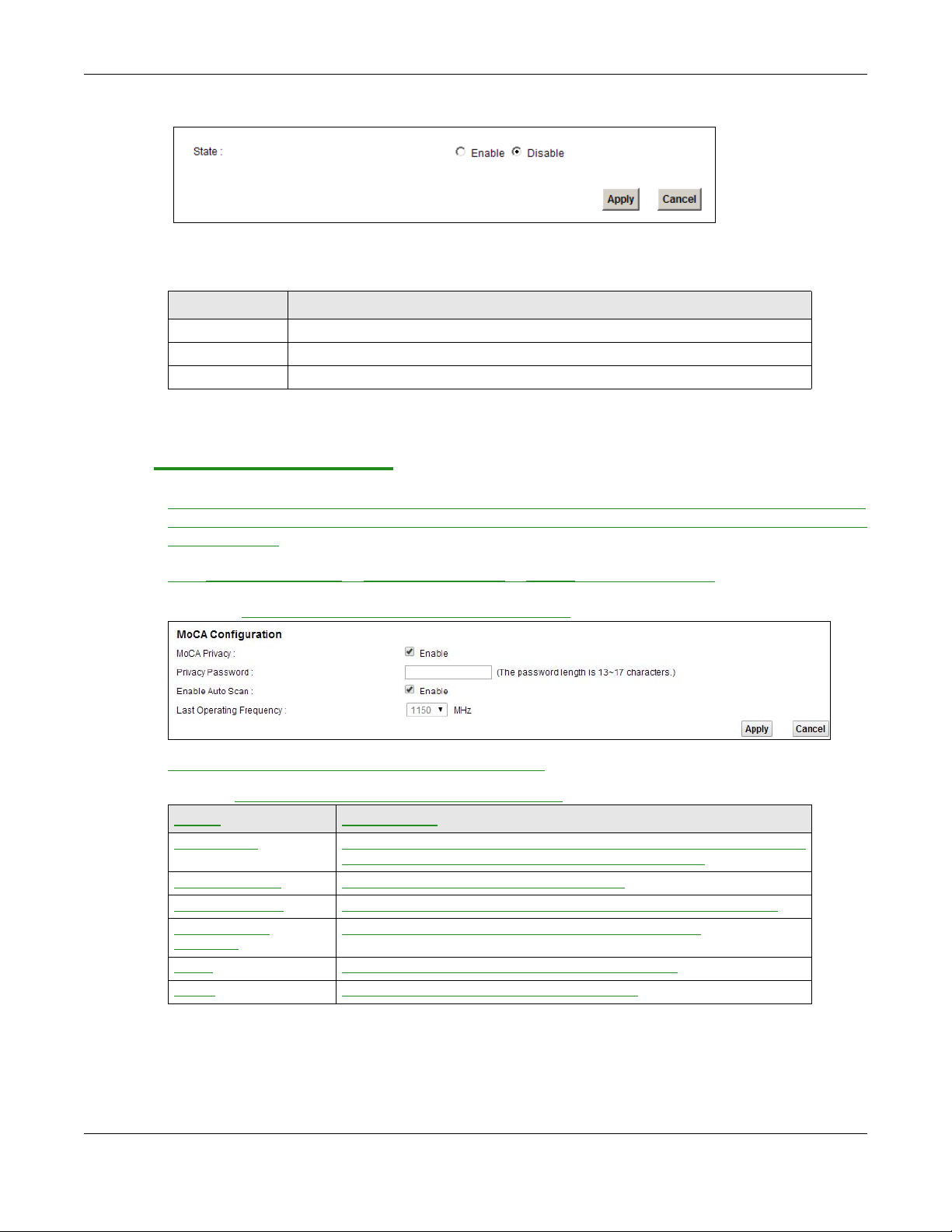
Figure 58 Network Settings > Home Networking > 5th Ethernet Port
The following table describes the fields in this screen.
Table 37 Network Settings > Home Networking > 5th Ethernet Port
LABEL DESCRIPTION
State Select Enable to use the Ethernet WAN port as a LAN port on the Device.
Apply Click Apply to save your changes back to the Device.
Cancel Click Cancel to exit this screen without saving.
8.10 The MoCA Screen
The VMG4381-B10A supports MoCA (Multimedia over Coax Alliance), which allows multimedia and
home networking over coaxial cable. Data communication and audio/video streaming are allowed at
the same time.
Chapter 8 Home Networking
Click Network Settings > Home Networking > MoCA to open this screen.
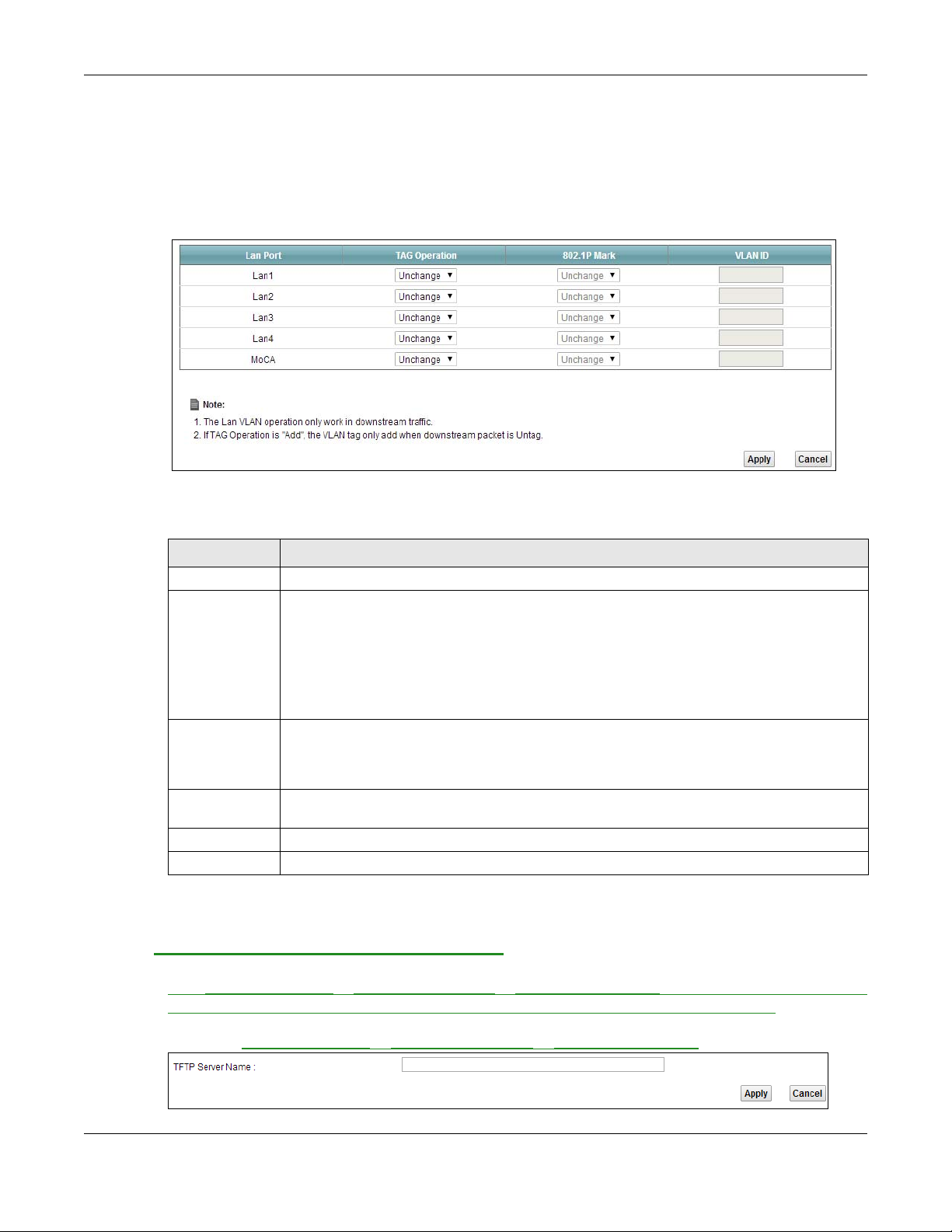
Figure 59 Network Settings > Home Networking > MoCA
The following table describes the fields in this screen.
Table 38 Network Settings > Home Networking > MoCA
LABEL DESCRIPTION
MoCA Privacy Select the check box to enable MoCA privacy . If this is enabled, all devices
connected via coaxial cable must use the same password.
Privacy Password Enter the password for the MoCA connection.
Enable Auto Scan Select the check box to enable auto scan for the operating frequency.
Last Operating
Frequency
Apply Click Apply to save your changes back to the Device.
Cancel Click Cancel to exit this screen without saving.
Manually select an operating frequency from the droplist.
VMG4381-B10A User’s Guide
151
Chapter 8 Home Networking
8.11 The LAN VLAN Screen
Click Network Setting > Home Networking > LAN VLAN to open this screen. Use this screen to
control the VLAN ID and IEEE 802.1p priority tags of traffic sent out through individual LAN ports.
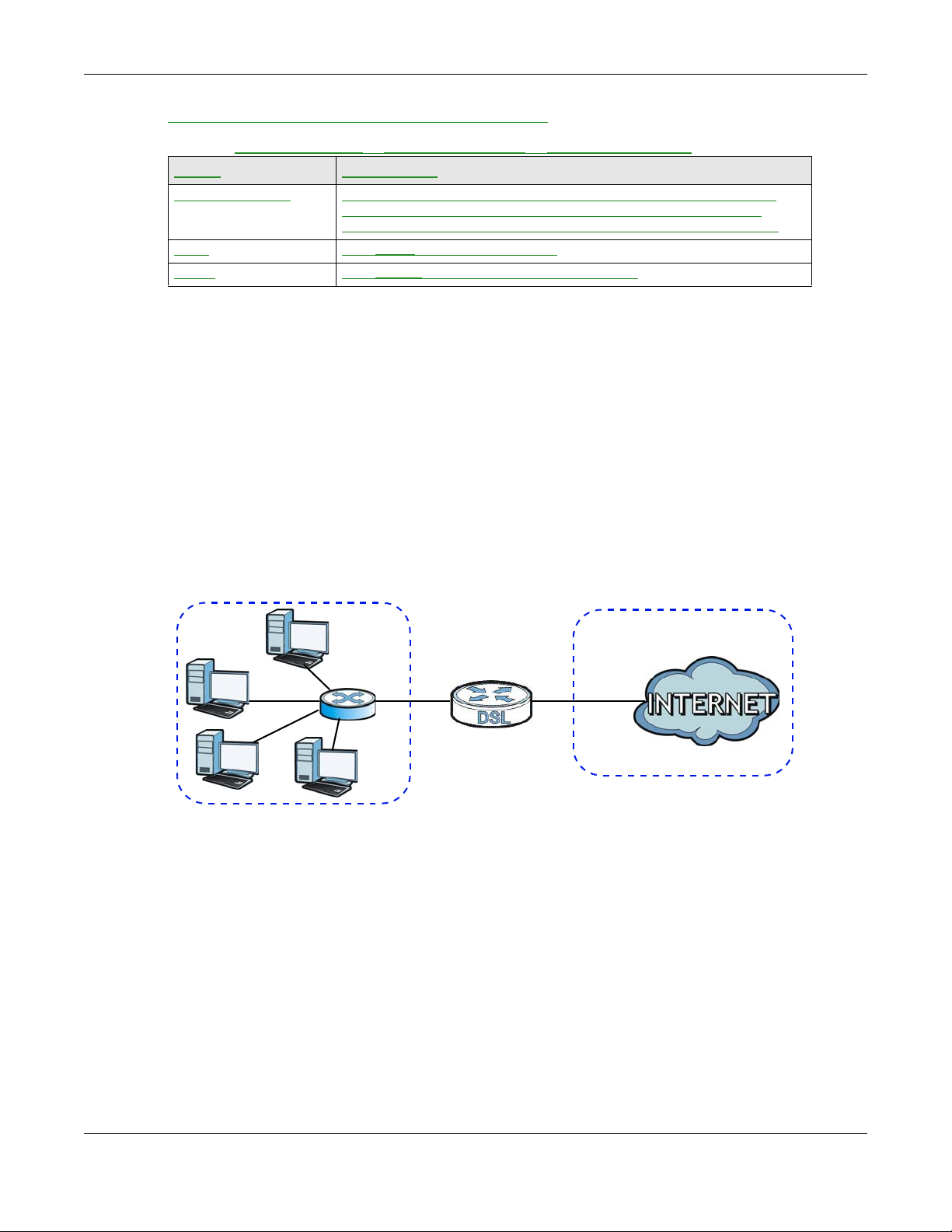
Figure 60 Network Setting > Home Networking > LAN VLAN
The following table describes the labels in this screen.
Table 39 Network Setting > Home Networking > LAN VLAN
LABEL DESCRIPTION
Lan Port These represent the Device’s LAN ports.
Tag Operation Select what you want the Device to do to the IEEE 802.1q VLAN ID and priority tags of
802.1P Mark Use this option to set what to do for the IEEE 802.1p priority tags when you add or remark
VLAN ID If you will add or remark tags for this LAN port’s downstream traffic, specify the VLAN ID
Apply Click Apply to save your changes.
Cancel
downstream traffic before sending it out through this LAN port.
• Unchange - Don’t do anything to the traffic’s VLAN ID and priority tags.
• Add - Add VLAN ID and priority tags to untagged traffic.
• Remove - Delete one tag from tagged traffic. If the frame has double tags, this removes
the outer tag. This does not affect untagged traffic.
• Remark - Change the value of the outer VLAN ID and priority tags.
the tags for a LAN port’s downstream traffic. Either select Unchange to not modify the
traffic’s priority tags or select an priority from 0 to 7 to use. The larger the number, the
higher the priority.
(from 0 to 4094) to use here.
Click Cancel to exit this screen without saving.
8.12 TFTP Server Name Screen
Click Network Setting > Home Networking > TFTP Server Name to open this screen. Use this
screen to access the TFTP (Trivial File Transfer Protocol) Server using DHCP option 66.
Figure 61 Network Setting > Home Networking > TFTP Server Name
VMG4381-B10A User’s Guide
152
Chapter 8 Home Networking
WAN
LAN
The following table describes the labels in this screen.
Table 40 Network Setting
LABEL DESCRIPTION
TFTP Server Name Type a name for the TFTP Server. This allows you to access the TFTP
Apply Click Apply to save your changes.
Cancel Click Cancel to exit this screen without saving.
> Home Networking > TFTP Server Name
server using DHCP option 66. However, option 66 (open standard)
supports only the IP address of the hostname or a single TFTP server.
8.13 Technical Reference
This section provides some technical background information about the topics covered in this
chapter.
8.13.1
LANs, WANs and the Device
The actual physical connection determines whether the Device ports are LAN or WAN ports. There
are two separate IP networks, one inside the LAN network and the other outside the WAN network
as shown next.
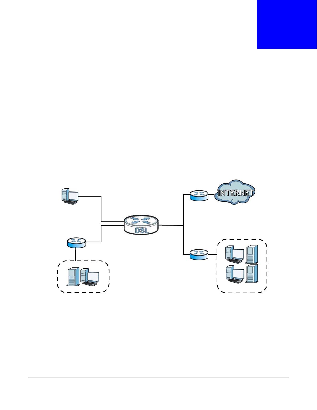
Figure 62 LAN and WAN IP Addresses
8.13.2 DHCP Setup
DHCP (Dynamic Host Configuration Protocol, RFC 2131 and RFC 2132) allows individual clients to
obtain TCP/IP configuration at start-up from a server. You can configure the Device as a DHCP
server or disable it. When configured as a server, the Device provides the TCP/IP configuration for
the clients. If you turn DHCP service off, you must have another DHCP server on your LAN, or else
the computer must be manually configured.
IP Pool Setup
The Device is pre-configured with a pool of IP addresses for the DHCP clients (DHCP Pool). See the
product specifications in the appendices. Do not assign static IP addresses from the DHCP pool to
your LAN computers.
VMG4381-B10A User’s Guide
153

8.13.3 DNS Server Addresses
DNS (Domain Name System) maps a domain name to its corresponding IP address and vice versa.
The DNS server is extremely important because without it, you must know the IP address of a
computer before you can access it. The DNS server addresses you enter when you set up DHCP are
passed to the client machines along with the assigned IP address and subnet mask.
There are two ways that an ISP disseminates the DNS server addresses.
• The ISP tells you the DNS server addresses, usually in the form of an information sheet, when
you sign up. If your ISP gives you DNS server addresses, enter them in the DNS Server fields in
the DHCP Setup screen.
• Some ISPs choose to disseminate the DNS server addresses using the DNS server extensions of
IPCP (IP Control Protocol) after the connection is up. If your ISP did not give you explicit DNS
servers, chances are the DNS servers are conveyed through IPCP negotiation. The Device
supports the IPCP DNS server extensions through the DNS proxy feature.
Please note that DNS proxy works only when the ISP uses the IPCP DNS server extensions. It
does not mean you can leave the DNS servers out of the DHCP setup under all circumstances. If
your ISP gives you explicit DNS servers, make sure that you enter their IP addresses in the
DHCP Setup screen.
Chapter 8 Home Networking
8.13.4 LAN TCP/IP
The Device has built-in DHCP server capability that assigns IP addresses and DNS servers to
systems that support DHCP client capability.
IP Address and Subnet Mask
Similar to the way houses on a street share a common street name, so too do computers on a LAN
share one common network number.
Where you obtain your network number depends on your particular situation. If the ISP or your
network administrator assigns you a block of registered IP addresses, follow their instructions in
selecting the IP addresses and the subnet mask.
If the ISP did not explicitly give you an IP network number, then most likely you have a single user
account and the ISP will assign you a dynamic IP address when the connection is established. If this
is the case, it is recommended that you select a network number from 192.168.0.0 to
192.168.255.0 and you must enable the Network Address Translation (NAT) feature of the Device.
The Internet Assigned Number Authority (IANA) reserved this block of addresses specifically for
private use; please do not use any other number unless you are told otherwise. Let's say you select
192.168.1.0 as the network number; which covers 254 individual addresses, from 192.168.1.1 to
192.168.1.254 (zero and 255 are reserved). In other words, the first three numbers specify the
network number while the last number identifies an individual computer on that network.
Once you have decided on the network number, pick an IP address that is easy to remember, for
instance, 192.168.1.1, for your Device, but make sure that no other device on your network is
using that IP address.
The subnet mask specifies the network number portion of an IP address. Your Device will compute
the subnet mask automatically based on the IP address that you entered. Y ou don't need to change
the subnet mask computed by the Device unless you are instructed to do otherwise.
VMG4381-B10A User’s Guide
154

Chapter 8 Home Networking
Private IP Addresses
Every machine on the Internet must have a unique address. If your networks are isolated from the
Internet, for example, only between your two branch offices, you can assign any IP addresses to
the hosts without problems. However, the Internet Assigned Numbers Authority (IANA) has
reserved the following three blocks of IP addresses specifically for private networks:
• 10.0.0.0 — 10.255.255.255
• 172.16.0.0 — 172.31.255.255
• 192.168.0.0 — 192.168.255.255
You can obtain your IP address from the IANA, from an ISP or it can be assigned from a private
network. If you belong to a small organization and your Internet access is through an ISP, the ISP
can provide you with the Internet addresses for your local networks. On the other hand, if you are
part of a much larger organization, you should consult your network administrator for the
appropriate IP addresses.
Note: Regardless of your particular situation, do not create an arbitrary IP address;
always follow the guidelines above. For more information on address assignment,
please refer to RFC 1597, “Ad dress All ocati on for Private Internets” and RFC 1466,
“Guidelines for Management of IP Address Space”.
VMG4381-B10A User’s Guide
155

Chapter 8 Home Networking
VMG4381-B10A User’s Guide
156
9.1 Overview
WAN
R1
R2
A
R3
LAN
The Device usually uses the default gateway to route outbound traffic from computers on the LAN
to the Internet. T o have the Device send data to devices not reachable through the default gateway,
use static routes.
For example, the next figure shows a computer (A) connected to the Device’s LAN interface. The
Device routes most traffic from A to the Internet through the Device’s default gateway (R1). You
create one static route to connect to services offered by your ISP behind router R2. You create
another static route to communicate with a separate network behind a router R3 connected to the
LAN.
Figure 63 Example of Routing Topology
HAPTER
C
9
Routing
9.1.1 What You Can Do in this Chapter
•Use the Static Route screen to view and set up static routes on the Device (Section 9.2 on page
158).
•Use the Policy Forwarding screen to configure policy routing on the Device. (Section 9.3 on
page 159).
•Use the RIP screen to set up RIP settings on the Device. (Section 9.4 on page 161).
VMG4381-B10A User’s Guide
157
9.2 The Routing Screen
Use this screen to view and configure the static route rules on the Device. Click Network Setting
> Routing > Static Route to open the following screen.
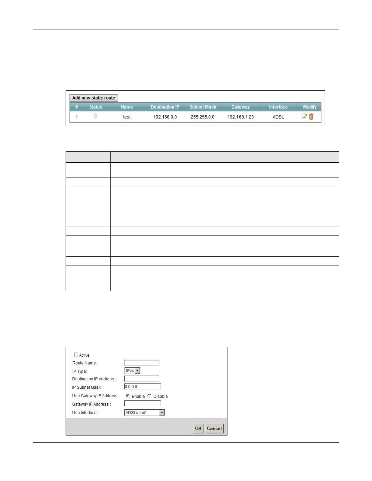
Figure 64 Network Setting > Routing > Static Route
The following table describes the labels in this screen.
Table 41 Network Setting > Routing > Static Route
LABEL DESCRIPTION
Add new static
route
# This is the index number of the entry.
Status This field displays whether the static route is active or not. A yellow bulb signifies that this
Name This is the name that describes or identifies this route.
Destination IP This parameter specifies the IP network address of the final destination. Routing is always
Subnet Mask This parameter specifies the IP network subnet mask of the final destination.
Gateway This is the IP address of the gateway. The gateway is a router or switch on the same
Interface This is the WAN interface used for this static route.
Modify Click the Edit icon to edit the static route on the Device.
Click this to configure a new static route.
route is active. A gray bulb signifies that this route is not active.
based on network number.
network segment as the device's LAN or WAN port. The gateway helps forward packets to
their destinations.
Chapter 9 Routing
Click the Delete icon to remove a static route from the Device. A window displays asking
you to confirm that you want to delete the rout e.
9.2.1 Add/Edit Static Route
Use this screen to add or edit a static route. Click Add new static route in the Routing screen or
the Edit icon next to the static route you want to edit. The screen shown next appears.
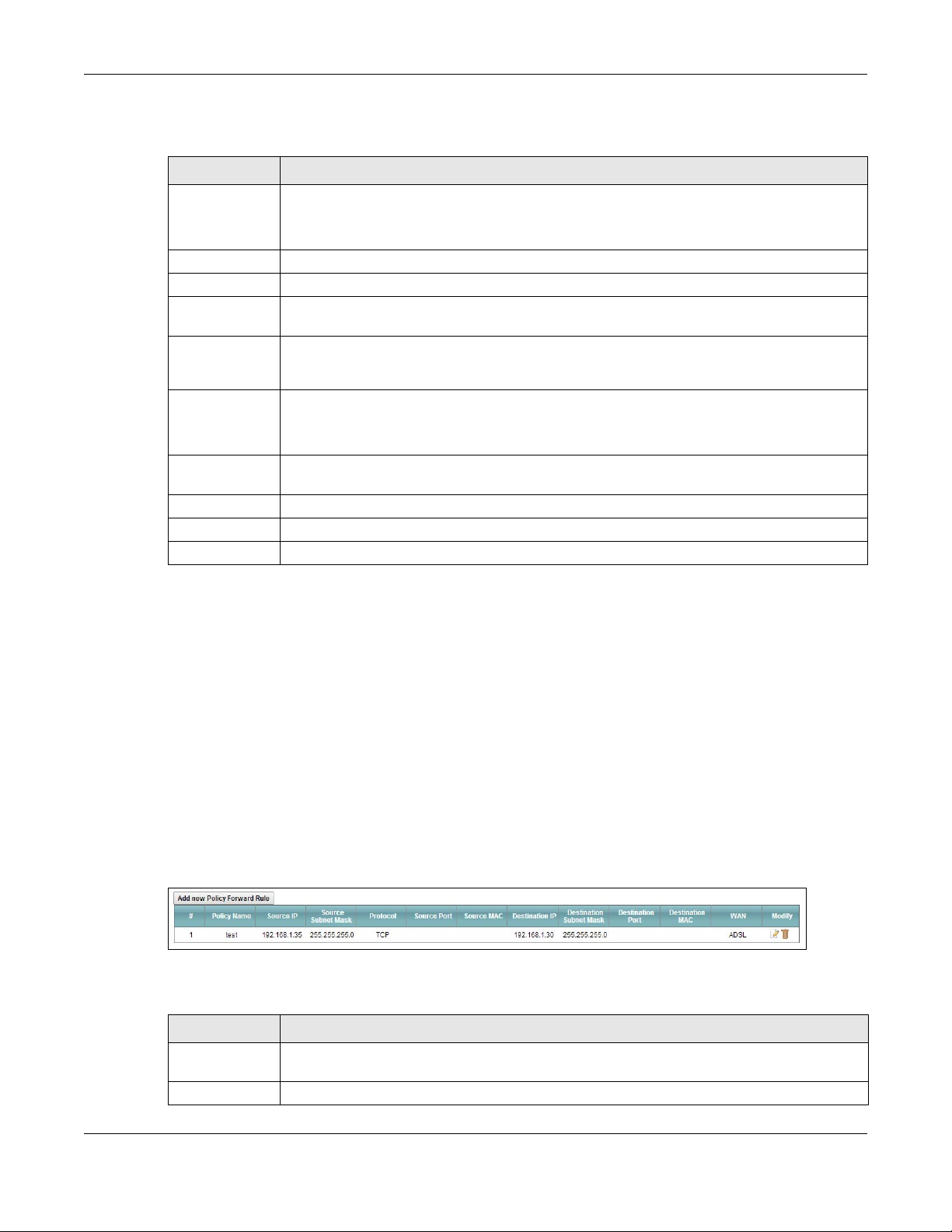
Figure 65 Routing: Add/Edit
VMG4381-B10A User’s Guide
158
Chapter 9 Routing
The following table describes the labels in this screen.
Table 42 Routing: Add/Edit
LABEL DESCRIPTION
Active This field allows you to activate/deactivate this static route.
Select this to enable the static route. Clear this to disable this static route without having to
delete the entry.
Route Name Enter a descriptive name for the static route.
IP Type Select whether your IP type is IPv4 or IPv6.
Destination IP
Address
IP Subnet Mask If you are using IPv4 and need to specify a route to a single host, use a subnet mask of
Use Gateway IP
Address
Gateway IP
Address
Use Interface Select the WAN interface you want to use for this static route.
Apply Click Apply to save your changes.
Cancel Click Cancel to exit this screen without saving.
Enter the IPv4 or IPv6 network address of the final destination.
255.255.255.255 in the subnet mask field to force the network number to be identical to
the host ID. Enter the IP subnet mask here.
The gateway is a router or swi tch on the same network segment as t he device's LAN o r WAN
port. The gateway helps forward packets to their destinations.
If you want to use the gateway IP address, select Enable.
Enter the IP address of the gateway.
9.3 The Policy Forwarding Screen
Traditionally, routing is based on the destination address only and the Device takes the shortest
path to forward a packet. Policy forwarding allows the Device to override the default routing
behavior and alter the packet forwarding based on the policy defined by the network administrator.
Policy-based routing is applied to outgoing packets, prior to the normal routing.
You can use source-based policy forwarding to direct traffic from different users through different
connections or distribute traffic among multiple paths for load sharing.
The Policy Forwarding screen let you view and configure routing policies on the Device. Click
Network Setting > Routing > Policy Forwarding to open the following screen.
Figure 66 Network Setting > Routing > Policy Forwarding
The following table describes the labels in this screen.
Table 43 Network Setting > Routing >Policy Forwarding
LABEL DESCRIPTION
Add new Policy
Forwar d Rule
# This is the index number of the entry.
Click this to create a new policy forwarding rule.
VMG4381-B10A User’s Guide
159
Chapter 9 Routing
Table 43 Network Setting > Routing >Policy Forwarding (continued)
LABEL DESCRIPTION
Policy Name This is the name of the rule.
Source IP This is the source IP address.
Source Subnet
Mask
Protocol This is the transport layer protocol.
Source Port This is the source port number.
WAN This is the WAN interface through which the traffic is routed.
Modify Click the Edit icon to edit this policy.
his is the source subnet mask address.
Click the Delete icon to remove a policy from the Device. A window displays asking you to
confirm that you want to delete the policy.
9.3.1 Add/Edit Policy Forwarding
Click Add new Policy Forward Rule in the Policy Forwarding screen or click the Edit icon next
to a policy. Use this screen to configure the required information for a policy route.
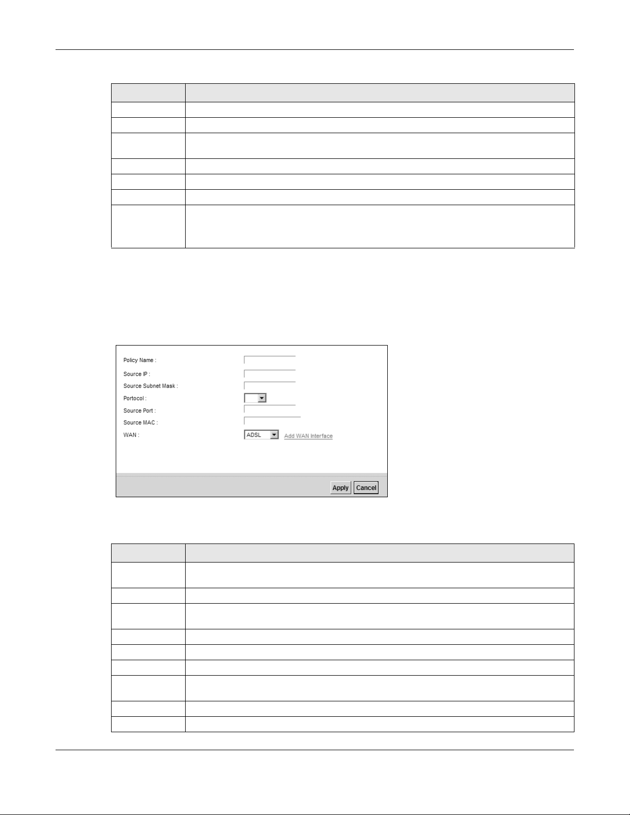
Figure 67 Policy Forwarding: Add/Edit
The following table describes the labels in this screen.
Table 44 Policy Forwarding: Add/Edit
LABEL DESCRIPTION
Policy Name Enter a descriptive name of up to 8 printable English keyboard characters, not including
spaces.
Source IP Enter the source IP address.
Source Subnet
Mask
Protocol Select the transport layer protocol (TCP or UDP).
Source Port Enter the source port number.
Source MAC Enter the source MAC address.
WAN Select a WAN interface through which the traffic is sent. You must have the WAN
Apply Click Apply to save your changes.
Cancel Click Cancel to exit this screen without saving.
Enter the source subnet mask address.
interface(s) already configured in the Broadband screens.
VMG4381-B10A User’s Guide
160
9.4 The RIP Screen
Routing Information Protocol (RIP, RFC 1058 and RFC 1389) allows a device to exchange routing
information with other routers.
Click Network Setting > Routing > RIP to open the RIP screen.
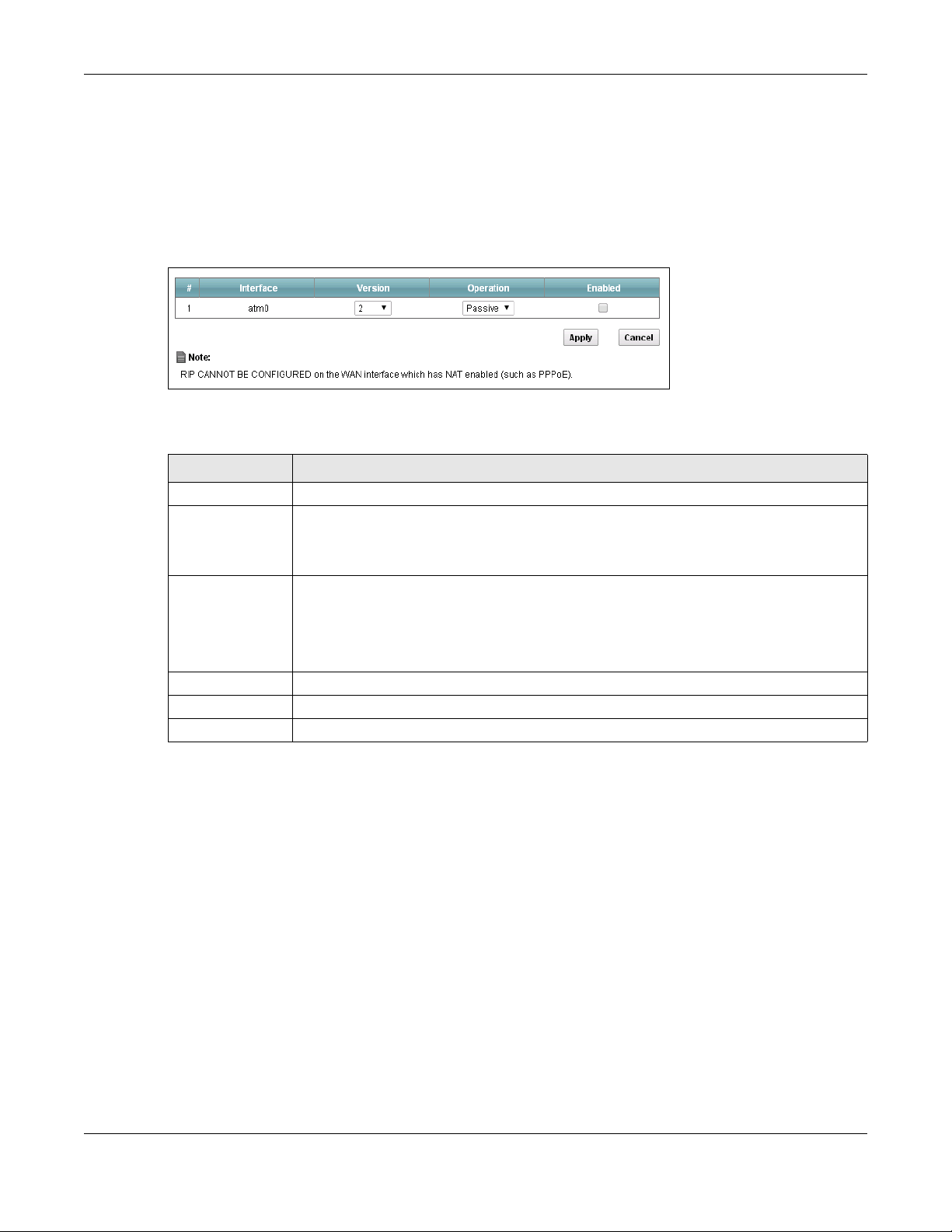
Figure 68 RIP
The following table describes the labels in this screen.
Table 45 RIP
LABEL DESCRIPTION
Interface This is the name of the interface in which the RIP setting is used.
Version The RIP version controls the format and the broadcas ti ng me th od of t he RIP packets that
the Device sends (it recognizes both formats when receiving). RIP version 1 is universally
supported but RIP version 2 carries more information. RIP version 1 is probably adequate
for most networks, unless you have an unusual network topology.
Operation Select Passive to have the Device update the routing table based on the RIP packets
received from neighbors but not advertise its route information to other routers in this
interface.
Select Active to have the Device advertise its route information and also listen for routing
updates from neighboring routers.
Enabled Select the check box to activate the settings.
Apply Click Apply to save your changes.
Cancel Click Cancel to exit this screen without saving.
Chapter 9 Routing
VMG4381-B10A User’s Guide
161

Chapter 9 Routing
VMG4381-B10A User’s Guide
162

10.1 Overview
Quality of Service (QoS) refers to both a network’s ability to deliver data with minimum delay, and
the networking methods used to control the use of bandwidth. Without QoS, all traffic data is
equally likely to be dropped when the network is congested. This can cause a reduction in network
performance and make the network inadequate for time-critical application such as video-ondemand.
Configure QoS on the Device to group and prioritize application traffic and fine-tune network
performance. Setting up QoS involves these steps:
1 Configure classifiers to sort traffic into different flows.
2 Assign priority and define actions to be performed for a classified traffic flow.
HAPTER
C
10
Quality of Service (QoS)
The Device assigns each packet a priority and then queues the packet accordingly . P ackets assigned
a high priority are processed more quickly than those with low priority if there is congestion,
allowing time-sensitive applications to flow more smoothly. Time-sensitive applications include both
those that require a low level of latency (delay) and a low level of jitter (variations in delay) such as
Voice over IP (VoIP) or Internet gaming, and those for which jitter alone is a problem such as
Internet radio or streaming video.
This chapter contains information about configuring QoS and editing classifiers.
10.1.1 What You Can Do in this Chapter
•The General screen lets you enable or disable QoS and set the upstream bandwidth (Section
10.3 on page 165).
•The Queue Setup screen lets you configure QoS queue assignment (Section 10.4 on page 166).
•The Class Setup screen lets you add, edit or delete QoS classifiers (Section 10.5 on page 168).
•The Policer Setup screen lets you add, edit or delete QoS policers (Section 10.5 on page 168).
•The Monitor screen lets you view the Device's QoS-related packet statistics (Section 10.7 on
page 175).
VMG4381-B10A User’s Guide
163
Chapter 10 Quality of Service (QoS)
Traffic
Time
Traffic Rate
Traffic
Time
Traffic Rate
(Before Traffic Shaping)
(After Traffic Shaping)
10.2 What You Need to Know
The following terms and concepts may help as you read through this chapter.
QoS versus Cos
QoS is used to prioritize source-to-destination traffic flows. All packets in the same flow are given
the same priority. CoS (class of service) is a way of managing traffic in a network by grouping
similar types of traffic together and treating each type as a class. You can use CoS to give different
priorities to different packet types.
CoS technologies include IEEE 802.1p layer 2 tagging and DiffServ (Differentiated Services or DS).
IEEE 802.1p tagging makes use of three bits in the packet header, while DiffServ is a new protocol
and defines a new DS field, which replaces the eight-bit ToS (Type of Service) field in the IP header.
Tagging and Marking
In a QoS class, you can configure whether to add or change the DSCP (DiffServ Code Point) value,
IEEE 802.1p priority level and VLAN ID number in a matched packet. When the packet passes
through a compatible network, the networking device, such as a backbone switch, can provide
specific treatment or service based on the tag or marker.
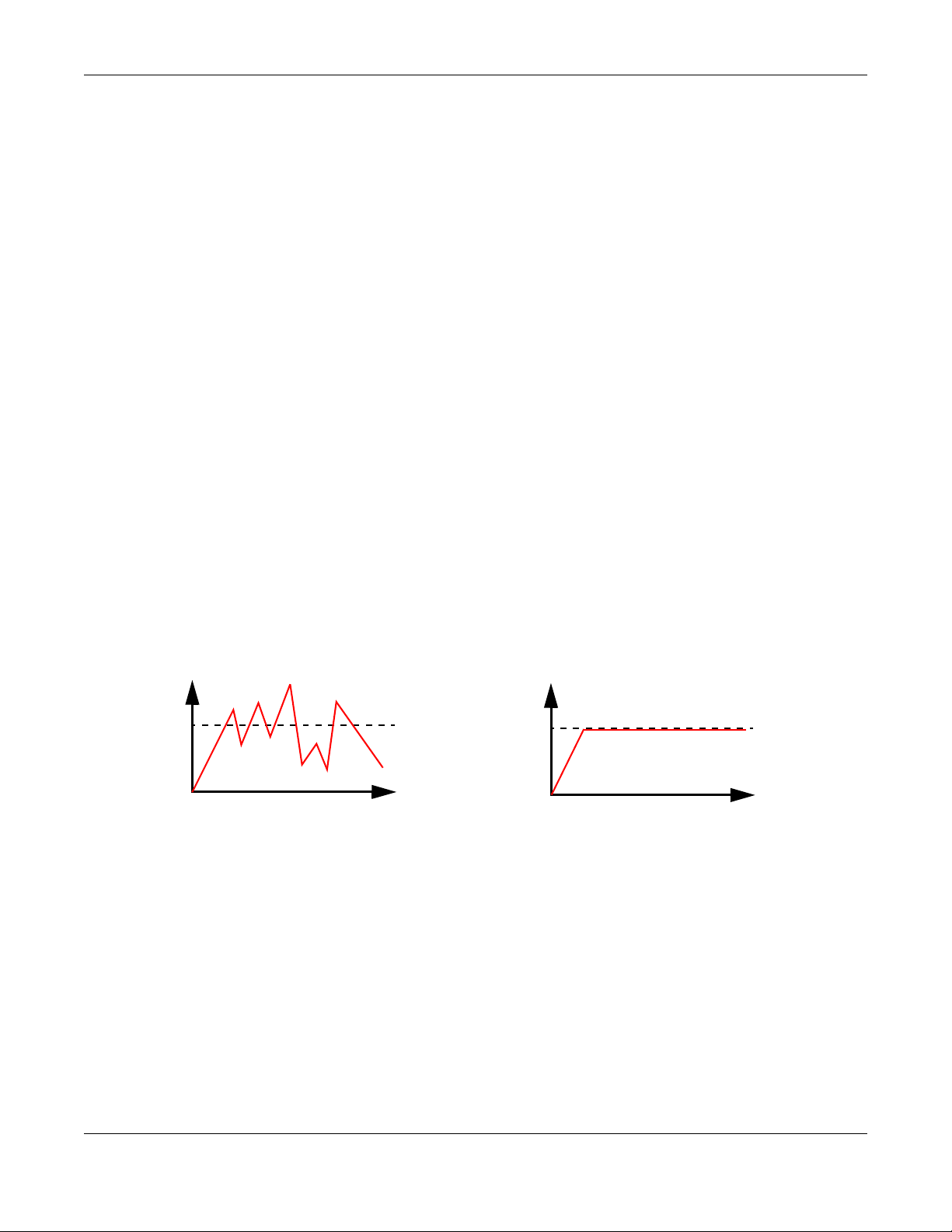
T raffic Shaping
Bursty traffic may cause network congestion. Traffic shaping regulates packets to be transmitted
with a pre-configured data transmission rate using buffers (or queues). Your Device uses the Token
Bucket algorithm to allow a certain amount of large bursts while keeping a limit at the aver age rate.
VMG4381-B10A User’s Guide
164
Chapter 10 Quality of Service (QoS)
Traffic
Time
Traffic Rate
Traffic
Time
Traffic Rate
(Before Traffic Policing) (After Traffic Policing)
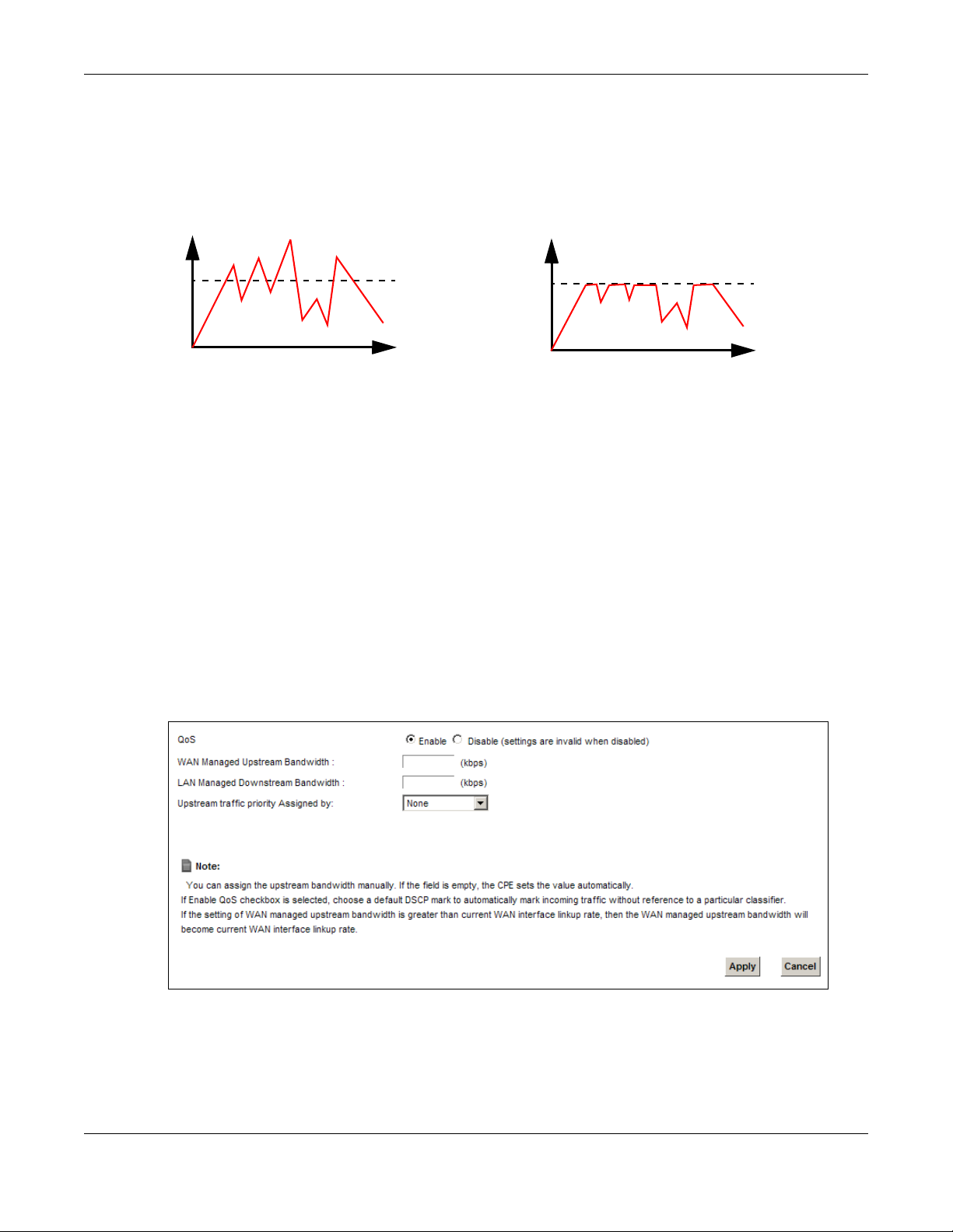
T raffic Policing
Traffic policing is the limiting of the input or output transmission rate of a class of traffic on the
basis of user-defined criteria. Traffic policing methods measure traffic flows against user-defined
criteria and identify it as either conforming, exceeding or violating the criteria.
The Device supports three incoming traffic metering algorithms: Token Bucket Filter (TBF), Single
Rate Two Color Maker (srTCM), and Two Rate Two Color Marker (trTCM). You can specify actions
which are performed on the colored packets. See Section 10.8 on page 176 for more information on
each metering algorithm.
10.3 The Quality of Service General Screen
Click Network Setting > QoS > General to open the screen as shown next.
Use this screen to enable or disable QoS and set the upstream bandwidth. See Section 10.1 on
page 163 for more information.
Figure 69 Network Settings > QoS > General
VMG4381-B10A User’s Guide
165

Chapter 10 Quality of Service (QoS)
The following table describes the labels in this screen.
Table 46 Network Setting > QoS > General
LABEL DESCRIPTION
QoS Se lect the Enable check box to turn on QoS to improve your network performance.
WAN Managed
Upstream
Bandwidth
LAN Managed
Downstream
Bandwidth
Enter the amount of upstream bandwidth for the WAN interfaces that you want to allocate
using QoS.
The recommendation is to set this speed to match the interfaces’ actual transmission speed.
For example, set the WAN int erfac es’ s pee d t o 100 000 k bps i f your Internet connection has
an upstream transmission speed of 100 Mbps.
You can set this number higher than the interfaces’ actual transmission speed. The Device
uses up to 95% of the DSL port’s actual upstream transmission speed even if you set this
number higher than the DSL port’s actual transmission speed.
You can also set this number lower than the interfaces’ actual transmission speed. This will
cause the Device to not use some of the interfaces’ available bandwidth.
If you leave this field blank, the Device automatically sets this number to be 95% of the
WAN interfaces’ actual upstream transmission speed.
Enter the amount of downstream bandwidth for the LAN interfaces (including WLAN) that
you want to allocate using QoS.
The recommendation is to set this speed to match the WAN interfaces’ actual transmission
speed. For example, set the LAN managed downstream bandwidth to 100000 kbps if you
use a 100 Mbps wired Ethernet WAN connection.
You can also set this number lower than the WAN inte rfaces’ actual tr ansmission speed. Thi s
will cause the Device to not use some of the interfaces’ available bandwidth.
If you leave this field blank, the Device automatically sets this to the LAN interfaces’
maximum supported connection speed.
Upstream
traffic priority
Assigned by
Apply Click Apply to save your changes.
Cancel Click Cancel to restore your previously saved settings.
Select how the Device assigns priorities to various upstream traffic flows.
• None: Disables auto priority mapping and has the Device put packets into the queues
according to your classification rules. Traffic which does not match any of the
classification rules is mapped into the default queue with the lowest priority.
• Ethernet Priority: Automatically assign priority based on the IEEE 802.1p priority level.
• IP Precedence: Automatically assign priority based on the first three bits of the TOS
field in the IP header.
• Packet Length: Automatically assign priority based on the packet size. Smaller packets
get higher priority since control, signaling, VoIP, internet gaming, or other real-time
packets are usually small while larger packets are usually best effort data packets like
file transfers.
10.4 The Queue Setup Screen
Click Network Setting > QoS > Queue Setup to open the screen as shown next.
Use this screen to configure QoS queue assignment.
VMG4381-B10A User’s Guide
166
Chapter 10 Quality of Service (QoS)
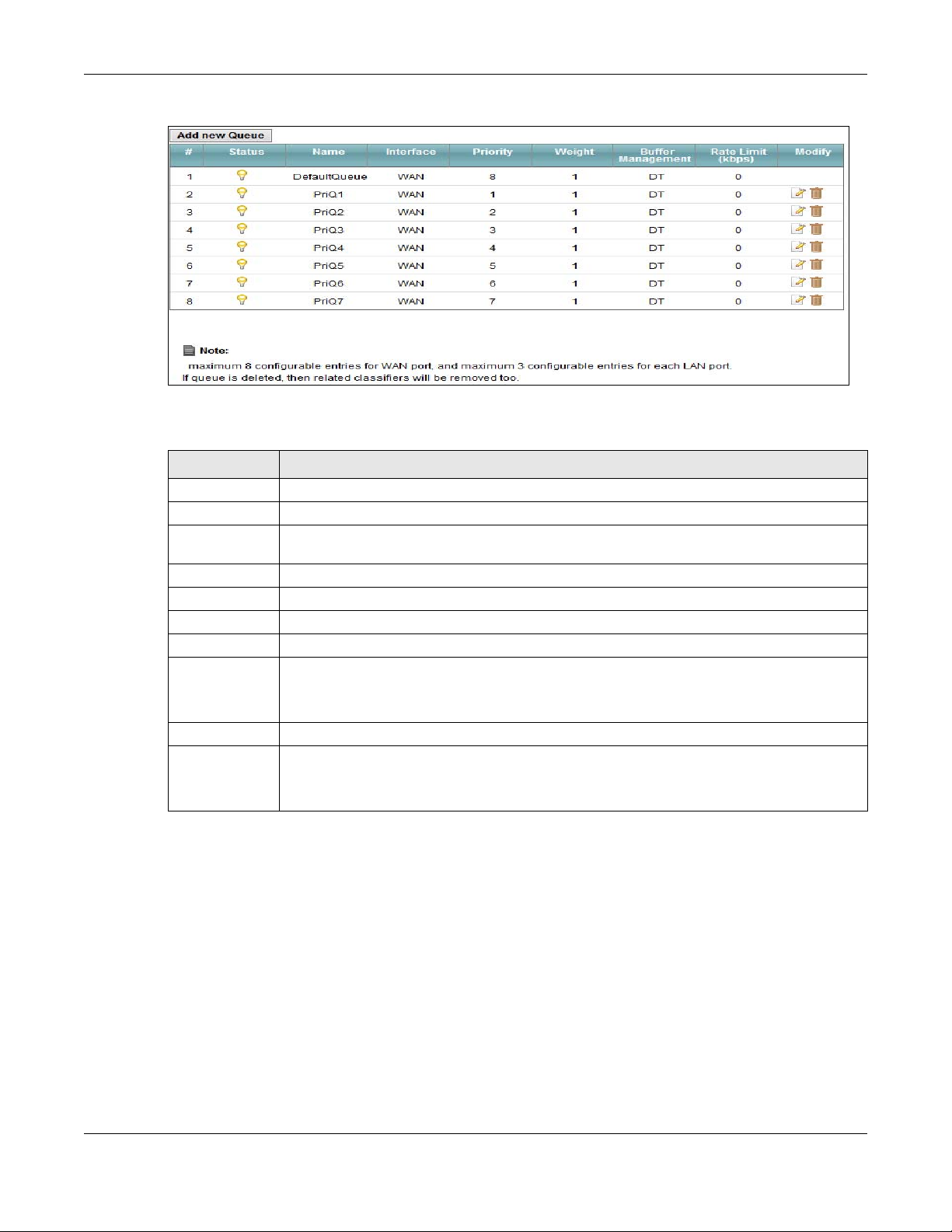
Figure 70 Network Setting > QoS > Queue Setup
The following table describes the labels in this screen.
Table 47 Network Setting > QoS > Queue Setup
LABEL DESCRIPTION
Add new Queue Click this button to create a new queue entry.
# This is the index number of the entry.
Status This field displays whether the queue is active or not. A yellow bulb signifies that this queue
Name This shows the descriptive name of this queue.
Interface This shows the name of the Device’s interface through which traffic in this queue passes.
Priority This shows the priority of this queue.
Weight This shows the weight of this queue.
Buffer
Management
Rate L imit This shows the maximum transmission rate allowed for traffic on this queue.
Modify Click the Edit icon to edit the queue.
is active. A gray bulb signifies that this queue is not active.
This shows the queue management algorithm used for this queue.
Queue management algorithms determine how the Device should handle packets when it
receives too many (network congestion).
Click the Delete icon to delete an existing queue. Note that subsequent rules move up by
one when you take this action.
VMG4381-B10A User’s Guide
167
Chapter 10 Quality of Service (QoS)
10.4.1 Adding a QoS Queue
Click Add new Queue or the edit icon in the Queue Setup screen to configure a queue.
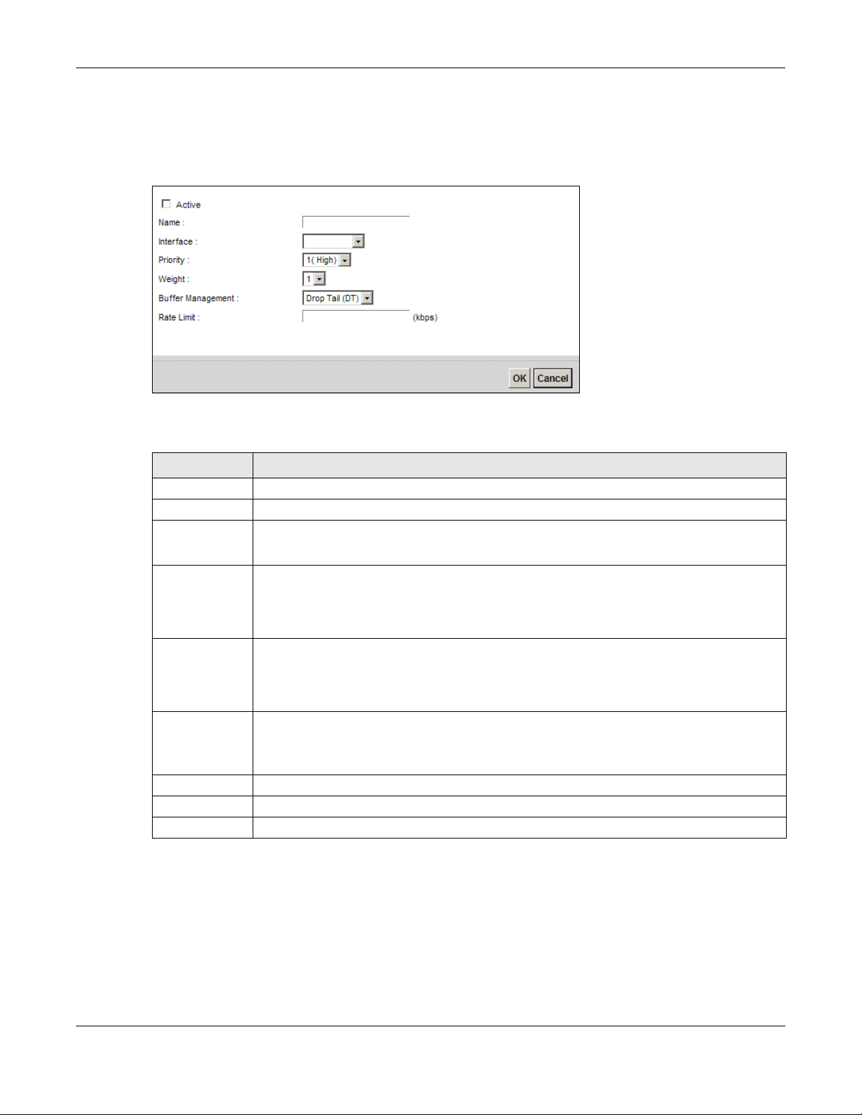
Figure 71 Queue Setup: Add
The following table describes the labels in this screen.
Table 48 Queue Setup: Add
LABEL DESCRIPTION
Active Select to enable or disable this queue.
Name Enter the descriptive name of this queue.
Interface Select the interface to which this queue is applied.
This field is read-only if you are editing the queue.
Priority Select the priority level (from 1 to 7) of this queue.
The smaller the number, the higher t he priority level. Traffic assigned to higher priority
queues gets through faster while traffi c in l ower priority queues is dropped if the network is
congested.
Weight Select the weight (from 1 to 8) of this queue.
If two queues have the same priority level, the Device divides the bandwidth across the
queues according to their weights. Queues with larger weights get more bandwidth than
queues with smaller weights.
Buffer
Management
Rate L imit Specify the maximum transmission rate (in Kbps) allowed for traffic on this queue.
OK Click OK to save your changes.
Cancel Click Cancel to exit this screen without saving.
This field displays Drop Tail (DT). Drop Tail (DT) is a simple queue management
algorithm that allows the Device buffer to accept as many packets as it can until it is full.
Once the buffer is full, new packets that arrive are dropped until there is space in the buffer
again (packets are transmitted out of it).
10.5 The Class Setup Screen
Use this screen to add, edit or delete QoS classifiers. A classifier groups traffic into data flows
according to specific criteria such as the source address, destination address, source port number,
destination port number or incoming interface. For example, you can configure a classifier to select
traffic from the same protocol port (such as Telnet) to form a flow.
VMG4381-B10A User’s Guide
168
Chapter 10 Quality of Service (QoS)
You can give different priorities to traffic that the Device forwards out through the WAN interface.
Give high priority to voice and video to make them run more smoothly. Similarly, give low priority
to many large file downloads so that they do not reduce the quality of other applications.
Click Network Setting > QoS > Class Setup to open the following screen.
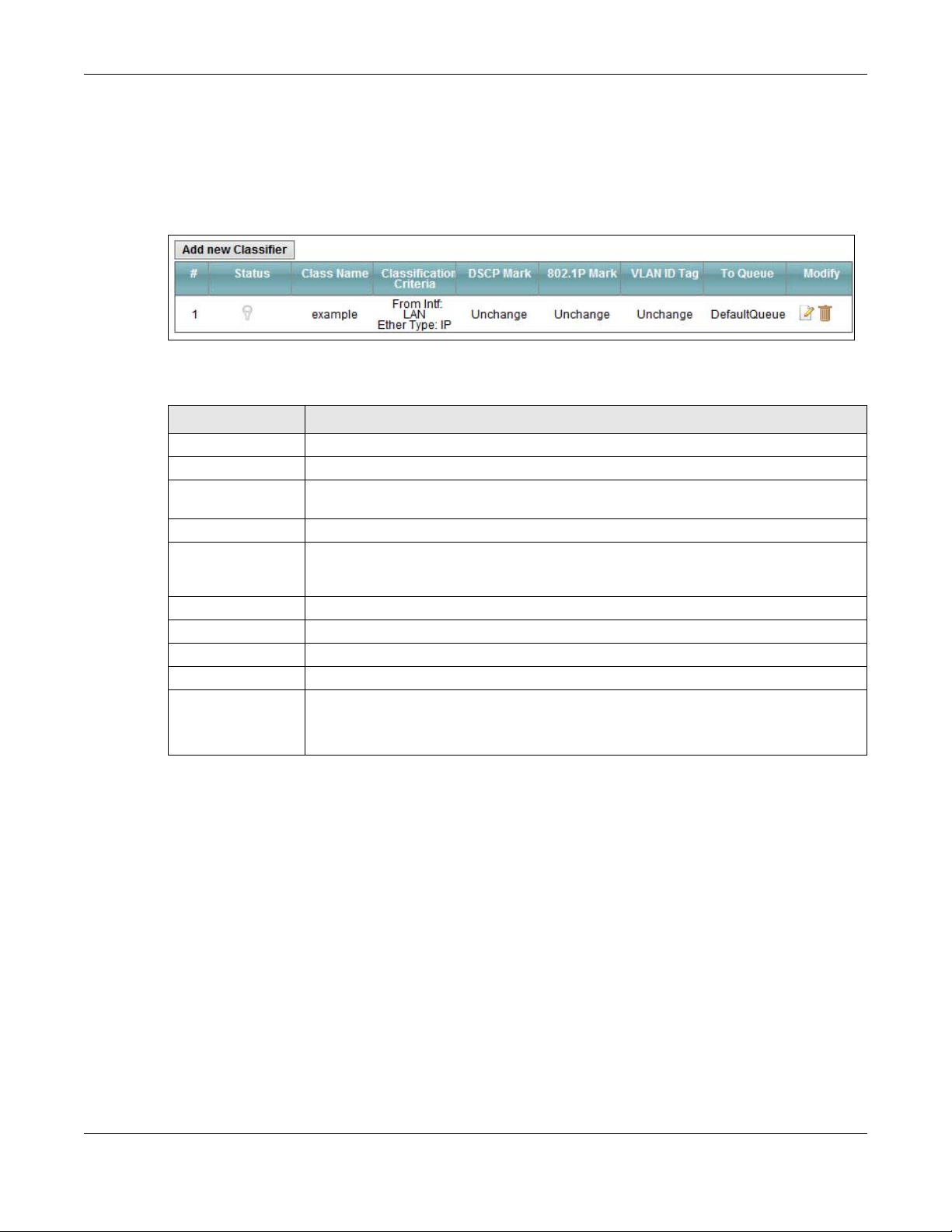
Figure 72 Network Setting > QoS > Class Setup
The following table describes the labels in this screen.
Table 49 Network Setting > QoS > Class Setup
LABEL DESCRIPTION
Add new Classifier Click this to create a new classifier.
# This is the index number of the entry.
Status This field displays whether the classifier is active or not. A yellow bulb signifies that this
Class Name This is the name of the classifier.
Classification
Criteria
DSCP Mark This is the DSCP number added to traffic of this classifier.
802.1P Mark This is the IEEE 802.1p priority level assigned to traffic of this classifier.
VLAN ID Tag This is the VLAN ID number assigned to traffic of this classifier.
To Queue This is the name of the queue in which traffic of this classifier is put.
Modify Click the Edit icon to edit the classifier.
classifier is active. A gray bulb signifies that this classifier is not act ive.
This shows criteria specified in this classifier, for example the interface from which
traffic of this class should come and the source MAC address of traffic that matches this
classifier.
Click the Delete icon to delete an existing classifier. Note that subsequent rules move
up by one when you take this action.
10.5.1 Add/Edit QoS Class
Click Add new Classifier in the Class Setup screen or the Edit icon next to a classifier to open
the following screen.
VMG4381-B10A User’s Guide
169
Chapter 10 Quality of Service (QoS)
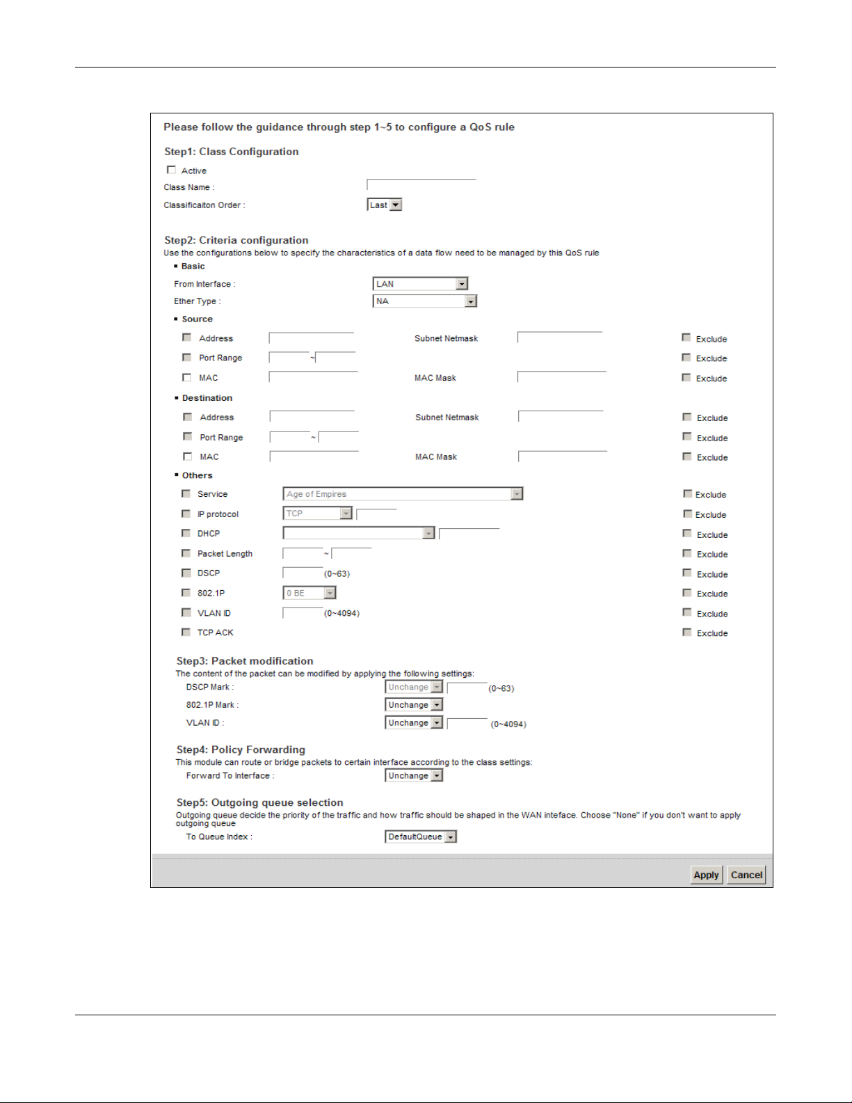
Figure 73 Class Setup: Add/Edit
VMG4381-B10A User’s Guide
170
Chapter 10 Quality of Service (QoS)
The following table describes the labels in this screen.
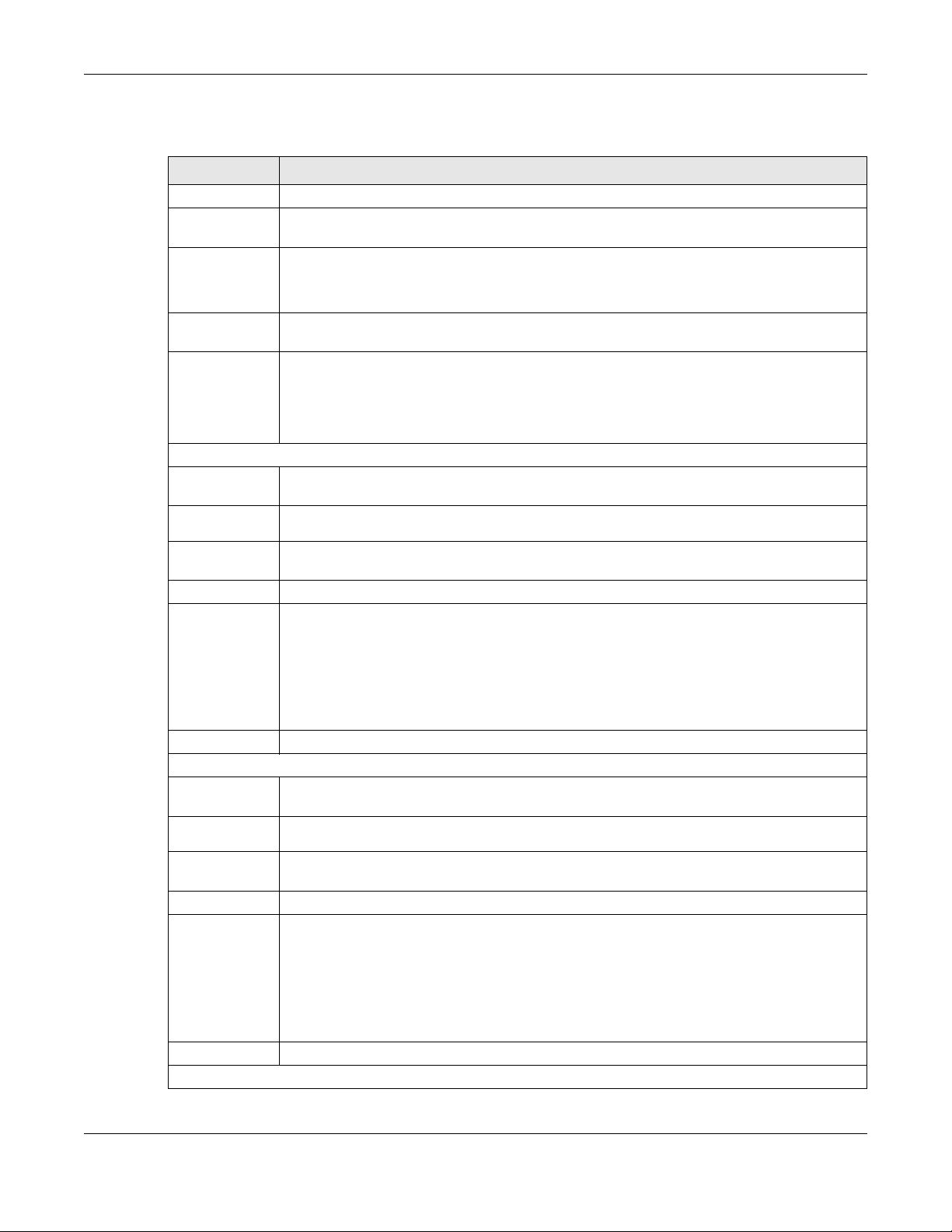
Table 50 Class Setup: Add/Edit
LABEL DESCRIPTION
Active Select this to enable this classifier.
Class Name Enter a descriptive name of up to 15 printable English keyboard characters, not including
Classification
Order
From Interface If you want to classify the traffic by an ingress interface, select an interface from the From
Ether Type Select a predefined application to configure a class for the matched traffic.
Source
Address Select the check box and enter the source IP address in dotted decimal notation. A blank
Subnet
Netmask
Port Range If you select TCP or UDP in the IP Protocol field, select the chec k box and enter the port
MAC Select the check box and enter the source MAC address of the packet.
MAC Mask Type the mask for the specified MAC address to determine which bits a packet’s MAC
Exclude Select this option to exclude the packets that match the specified criteria from this classifier.
Destination
Address Select the check box and enter the source IP address in dotted decimal notation. A blank
Subnet
Netmask
Port Range If you select TCP or UDP in the IP Protocol field, select the chec k box and enter the port
MAC Select the check box and enter the source MAC address of the packet.
MAC Mask Type the mask for the specified MAC address to determine which bits a packet’s MAC
spaces.
Select an existing number for where you want to put this classifier to move the classifier to
the number you selected after clicking Apply.
Select Last to put this rule in the back of the classifier list.
Interface drop-down list box.
If you select IP, you also need to configure source or destination MAC address, IP address,
DHCP options, DSCP value or the protocol type.
If you select 802.1Q, you can configure an 802.1p priority level.
source IP address means any source IP address.
Enter the source subnet mask.
number(s) of the source.
address should match.
Enter “f” for each bit of the specified source MAC address that the traffic’s MAC address
should match. Enter “0” for the bit(s) of the matched tr affi c’s MAC address, which can be of
any hexadecimal character(s). For example, if you set the MAC address to
00:13:49:00:00:00 and the mask to ff:ff:ff:00:00:00, a packet with a MAC address of
00:13:49:12:34:56 m atches this criteria.
Exclude Select this option to exclude the packets that match the specified criteria from this classifier.
Others
VMG4381-B10A User’s Guide
171

Chapter 10 Quality of Service (QoS)
Table 50 Class Setup: Add/Edit (continued)
LABEL DESCRIPTION
Service This field is available only when you select IP in the Ether Type field.
This field simplifies classifier configuration by allowing you to select a predefined
application. When you select a predefined application, you do not configure the rest of the
filter fields.
IP Protocol This field is available only when you select IP in the Ether Type field.
Select this option and select the protocol (service type) from TCP, UDP, ICMP or IGMP. If
you select User defined, enter the protocol (service ty pe) number.
DHCP This field is available only when you select IP in the Ether Type field.
Select this option and select a DHCP option.
If you select Vendor Class ID (DHCP Option 60), enter the Vendor Class Identifier
(Option 60) of the matched traffic, such as the type of the hardware or firmware.
If you select User Class ID (DHCP Option 77), enter a string that identifies the user’s
category or application type in the matched DHCP packets.
Packet
Length
DSCP This field is available on ly when you select IP in the Ether Type field.
802.1P This field is available only when you select 802.1Q in the Ether Type field.
VLAN ID This field is available only when you select 802.1Q in the Ether Type field.
This field is available only when you select IP in the Ether Type field.
Select this option and enter the minimum and maximu m packet lengt h (from 46 to 1500) in
the fields provided.
Select this option and specify a DSCP (DiffServ Code Point) number between 0 and 63 in the
field provided.
Select this option and select a priority level (between 0 and 7) from the drop-down list box.
"0" is the lowest priority level and "7" is the highest.
Select this option and specify a VLAN ID number.
TCP ACK This field is available only when you select IP in the Ether Type field.
If you select this option, the matched TCP packets must contain the ACK (Acknowledge)
flag.
Exclude Select this option to exclude the packets that match the specified criteria from this classifier.
DSCP Mark This field is available only when you select IP in the Ether Type field.
If you select Mark, enter a DSCP value with which the Device replaces the DSCP field in the
packets.
If you select Unchange, the Device keep the DSCP field in the packets.
802.1P Mark Select a priority level with which the Device replaces the IEEE 802.1p priority field in the
packets.
If you select Unchange, the Device keep the 802.1p priority field in the packets.
VLAN ID If you select Remark, enter a VLAN ID number with which the Device replaces the VLAN ID
of the frames.
If you select Remove, the Device deletes the VLAN ID of the frames before forwarding
them out.
If you select Add, the Device treat all matched traffic untagged and add a second VLAN ID.
If you select Unchange, the Device keep the VLAN ID in the packets.
Forwar d to
Interface
Select a WAN interface through which traffic of this class wil l be forwarded o ut. If you select
Unchange, the Device forward traffic of this class according to the default routing table.
VMG4381-B10A User’s Guide
172
Chapter 10 Quality of Service (QoS)
Table 50 Class Setup: Add/Edit (continued)
LABEL DESCRIPTION
To Queue Index Select a queue that applies to this class.
You should have configured a queue in the Queue Setup screen already.
Apply Click Apply to save your changes.
Cancel Click Cancel to exit this screen without saving.
10.6 The QoS Policer Setup Screen
Use this screen to configure QoS policers that allow you to limit the transmission rate of incoming
traffic. Click Network Setting > Qo S > Policer Setup. The screen appears as shown.
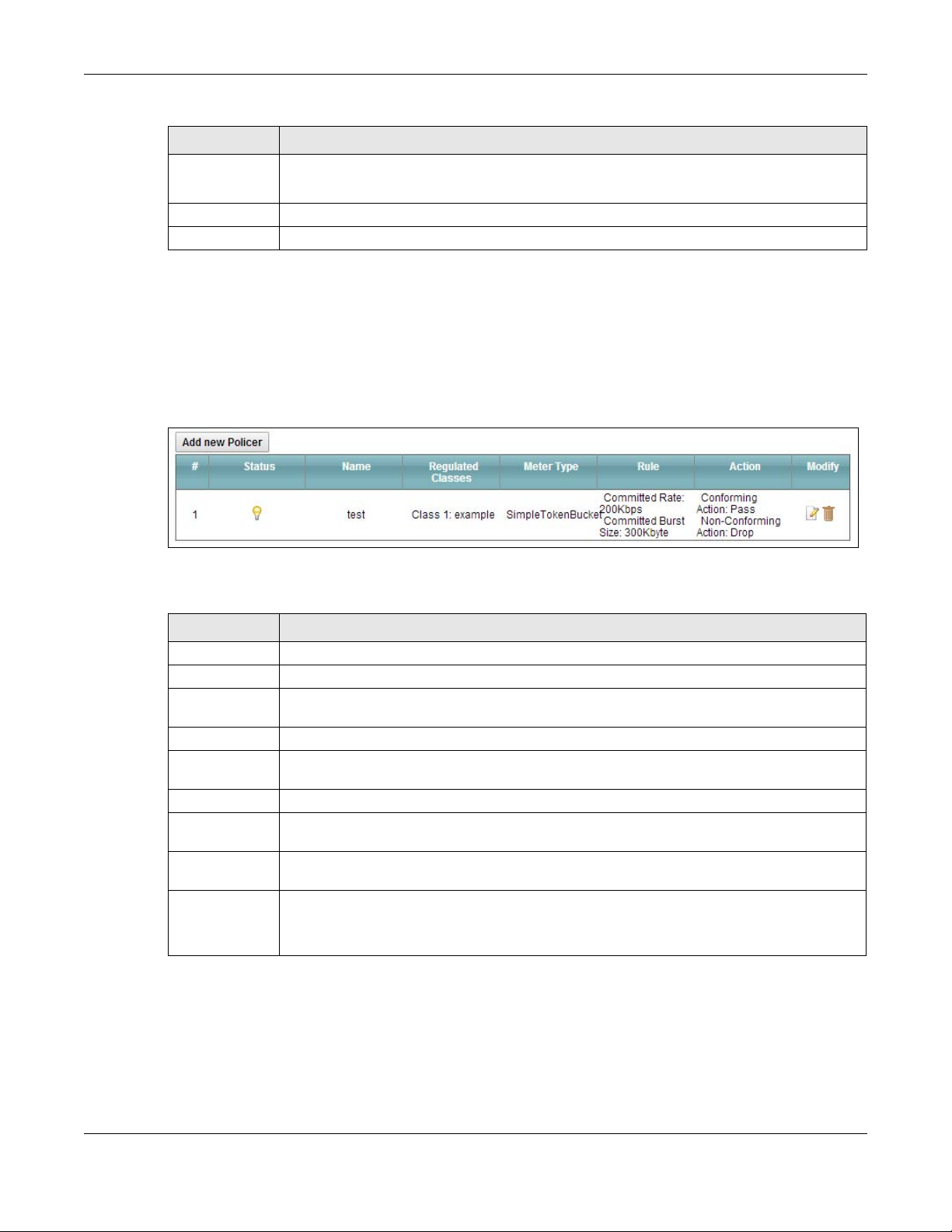
Figure 74 Network Setting > QoS > Policer Setup
The following table describes the labels in this screen.
Table 51 Network Setting > QoS > Policer Setup
LABEL DESCRIPTION
Add new Policer Click this to create a new entry.
# This is the index number of the entry.
Status This field displays whether the policer is active or not. A yellow bulb signifies that this
policer is active. A gray bulb signifies that this policer is not active.
Name This field displays the descriptive name of this policer.
Regulated
Classes
Meter Type This field displays the type of QoS metering algorithm used in this policer.
Rule These are the rates and burst sizes against which the policer checks the traffic of the
Action This shows the how the policer has the Device treat different types of traffic belonging to
Modify Click the Edit icon to edit the policer.
This field displays the name of a QoS classifier
member QoS classes.
the policer’s member QoS classes.
Click the Delete icon to delete an existing policer. Note that subsequent rules move up by
one when you take this action.
VMG4381-B10A User’s Guide
173
Chapter 10 Quality of Service (QoS)
10.6.1 Add/Edit a QoS Policer
Click Add new Policer in the Policer Setup screen or the Edit icon next to a policer to show the
following screen.
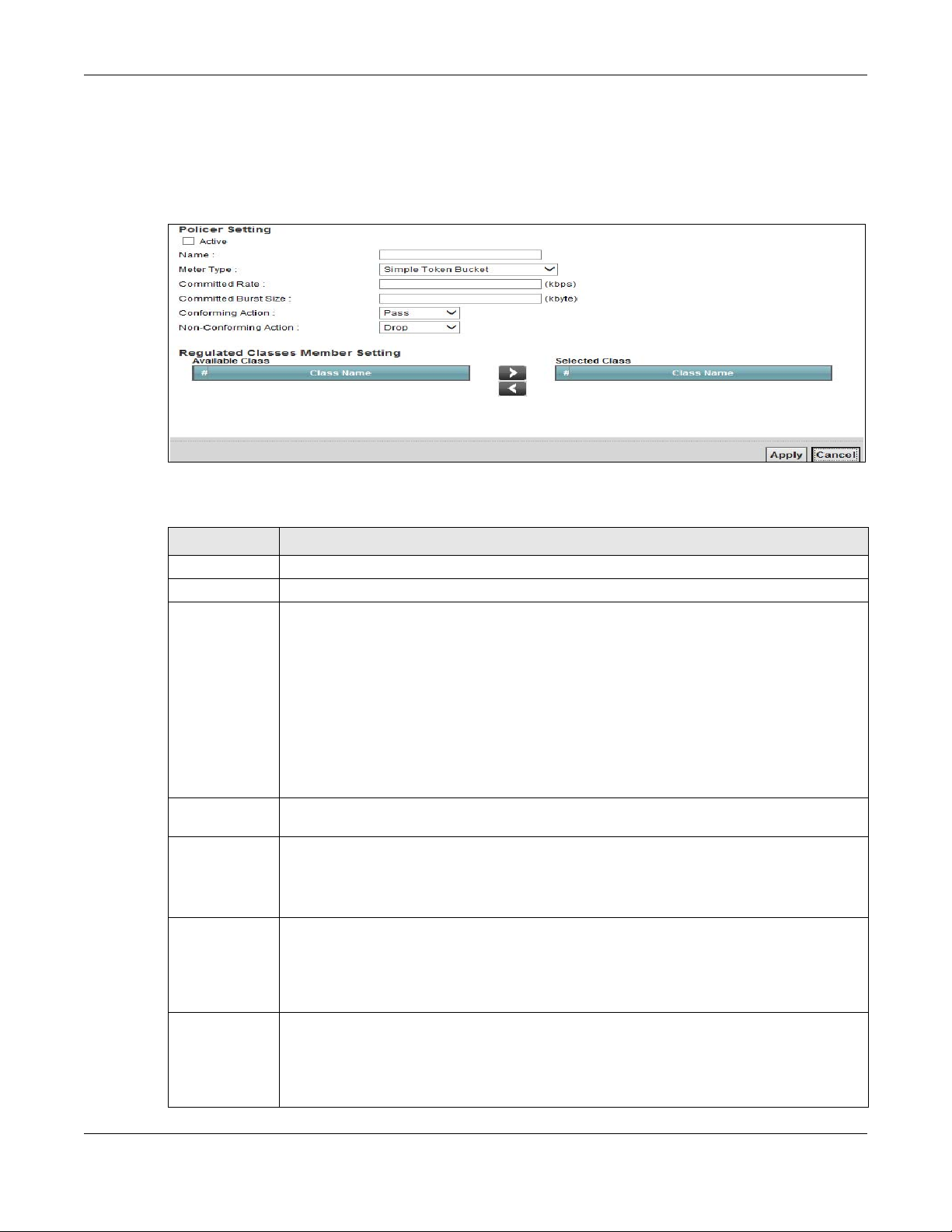
Figure 75 Policer Setup: Add/Edit
The following table describes the labels in this screen.
Table 52 Policer Setup: Add/Edit
LABEL DESCRIPTION
Active Select the check box to activate this policer.
Name Enter the descriptive name of this policer.
Meter Type This shows the traffic metering algorithm used in this policer.
The Simple Token Bucket algorithm uses tokens in a bucket to control when traffic can be
transmitted. Each token represents one byte. The algorithm allows bursts of up to b bytes
which is also the bucket size.
The Single Rate Three Color Marker (srTCM) is based on the token bucket filter and
identifies packets by comparing them to the Committed Information Rate (CIR), the
Committed Burst Size (CBS) and the Excess Burst Size (EBS).
The Two Rate Three Color Marker (trTCM) is based on the token bucket filter and
identifies packets by comparing them to the Committed Information Rate (CIR) and the
Peak Information Rate (PIR).
Committed
Rate
Committed
Burst Size
Conforming
Action
NonConforming
Action
Specify the committed rate. When the incoming traffic rate of the member QoS classes is
less than the committed rate, the device applies the conforming action to the traffic.
Specify the committed burst size for packet bursts. This must be equal to or less than the
peak burst size (two rate three color) or exce ss burst size (single r ate three color) if it is also
configured.
This is the maximum size of the (first) token bucket in a traffic metering algorithm.
Specify what the Device does for packets within the committed rate and burst size (green-
marked packets).
• Pass: Send the packets without modification.
• DSCP Mark: Change the DSCP mark value of the packets. Enter the DSCP mark value to
use.
Specify what the Device does for packets that exceed the excess burst size or peak rate and
burst size (red-marked packets).
• Drop: Discard the packets.
• DSCP Mark: Change the DSCP mark value of the packets. Enter the DSCP mark value to
use. The packets may be dropped if there is congestion on the network.
VMG4381-B10A User’s Guide
174
Chapter 10 Quality of Service (QoS)
Table 52 Policer Setup: Add/Edit
LABEL DESCRIPTION
Available Class
Select a QoS classifier to apply this QoS policer to traffic that matches the QoS classifier.
Selected Class
Apply Click Apply to save your changes.
Cancel Click Cancel to exit this screen without saving.
Highlight a QoS classifier in the Available Class box and use the > button to move it to the
Selected Class box.
To remove a QoS classifier from the Selected Class box, select it and use the < button.
10.7 The QoS Monitor Screen
To view the Device’s QoS packet statistics, click Network Setting > QoS > Monitor. The screen
appears as shown.
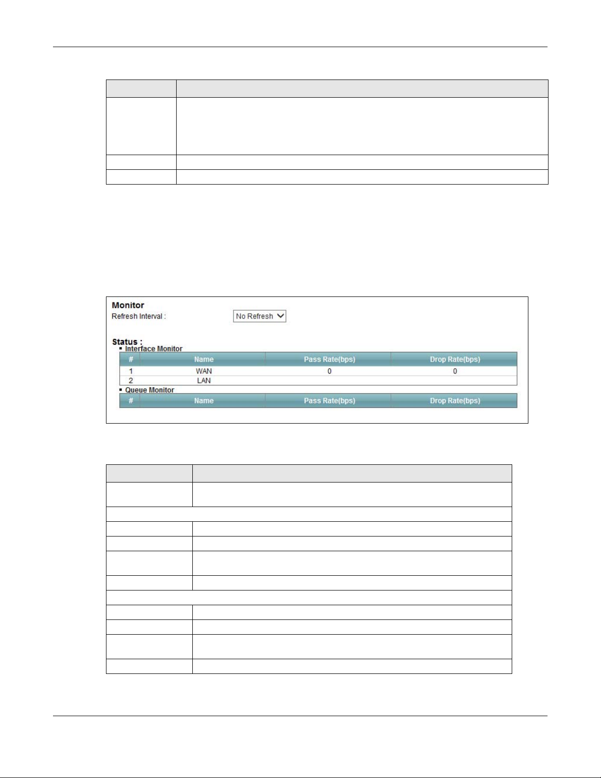
Figure 76 Network Setting > QoS > Monitor
The following table describes the labels in this screen.
Table 53 Network Setting > QoS > Monitor
LABEL DESCRIPTION
Refresh Interval Enter how often you want the Device to update t his screen. Se lect No Refresh
to stop refreshing statistics.
Interface Monitor
# This is th e index number of the entry.
Name This shows the name of the interface on the Device.
Pass Rate This shows how many packets forwarded to this interface are transmitted
successfully.
Drop Rate This shows how many packets forwarded to this interface are dropped.
Queue Monitor
# This is th e index number of the entry.
Name This shows the name of the queue.
Pass Rate This shows how many packets assigned to this queue are transmitted
successfully.
Drop Rate This shows how many packets assigned to this qu eue are dropped.
VMG4381-B10A User’s Guide
175

Chapter 10 Quality of Service (QoS)
10.8 Technical Reference
The following section contains additional technical information about the Device features described
in this chapter.
IEEE 802.1Q Tag
The IEEE 802.1Q standard defines an explicit VLAN tag in the MAC header to identify the VLAN
membership of a frame across bridges. A VLAN tag includes the 12-bit VLAN ID and 3-bit user
priority. The VLAN ID associates a frame with a specific VLAN and provides the information that
devices need to process the frame across the network.
IEEE 802.1p specifies the user priority field and defines up to eight separate traffic types. The
following table describes the traffic types defined in the IEEE 802.1d standard (which incorporates
the 802.1p).
Table 54 IEEE 802.1p Priority Level and Traffic Type
PRIORITY
LEVEL
Level 7 Typically used for network control traffic such as router configuration messages.
Level 6 Typically used for voice traffic that is especially sensitive to jitter (jitter is the
Level 5 Typically used for video that consumes high ban dwidth and is sensitive to jitter.
Level 4 Typically used for controlled load, latency-sensitive traffic such as SNA (Systems
Level 3 Typically used for “excellent effort” or better than best effort and would include
Level 2 This is for “spare bandwidth”.
Level 1 This is typically used for non-critical “background” traffic such as bulk transfers that
Level 0 Typically used for best-effort traffic.
TRAFFIC TYPE
variations in delay).
Network Architecture) transactions.
important business traffic that can tolerate some delay.
are allowed but that should not affect other applications and users.
DiffServ
QoS is used to prioritize source-to-destination traffic flows. All packets in the flow are given the
same priority. You can use CoS (class of service) to give different priorities to different packet
types.
DiffServ (Differentiated Services) is a class of service (CoS) model that marks packets so that they
receive specific per-hop treatment at DiffServ-compliant network devices along the route based on
the application types and traffic flow. Packets are marked with DiffServ Code Points (DSCPs)
indicating the level of service desired. This allows the intermediary DiffServ-compliant network
devices to handle the packets differently depending on the code points without the need to
negotiate paths or remember state information for every flow. In addition, applications do not have
to request a particular service or give advanced notice of where the traffic is going.
DSCP and Per-Hop Behavior
DiffServ defines a new Differentiated Services (DS) field to replace the Type of Service (TOS) field
in the IP header. The DS field contains a 2-bit unused field and a 6-bit DSCP field which can define
up to 64 service levels. The following figure illustrates the DS field.
VMG4381-B10A User’s Guide
176

Chapter 10 Quality of Service (QoS)
DSCP is backward compatible with the three precedence bits in the ToS octet so that non-DiffServ
compliant, ToS-enabled network device will not conflict with the DSCP mapping.
DSCP (6 bits) Unused (2 bits)
The DSCP value determines the forwarding behavior, the PHB (Per-Hop Behavior), that each packet
gets across the DiffServ network. Based on the marking rule, different kinds of traffic can be
marked for different kinds of forwarding. Resources can then be allocated according to the DSCP
values and the configured policies.
IP Precedence
Similar to IEEE 802.1p prioritization at layer-2, you can use IP precedence to prioritize packets in a
layer-3 network. IP precedence uses three bits of the eight-bit ToS (Type of Service) field in the IP
header. There are eight classes of services (ranging from zero to seven) in IP precedence. Zero is
the lowest priority level and seven is the highest.
Automatic Priority Queue Assignment
If you enable QoS on the Device, the Device can automatically base on the IEEE 802.1p priority
level, IP precedence and/or packet length to assign priority to traffic which does not match a class.
The following table shows you the internal layer-2 and layer-3 QoS mapping on the Device. On the
Device, traffic assigned to higher priority queues gets through faster while traffic in lower index
queues is dropped if the network is congested.
Table 55 Internal Layer2 and Layer3 QoS Mapping
LAYER 2 LAYER 3
PRIORITY
QUEUE
IEEE 802.1P USER
PRIORITY
(ETHERNET
TO S (IP
PRECEDENCE)
DSCP
IP PACKET
LENGTH (BYTE)
PRIORITY)
0 1 0 000000
12
2 0 0 000000 >1100
3 3 1 001110
001100
001010
001000
4 4 2 010110
010100
010010
010000
5 5 3 011110
250~1100
<250
011100
011010
011000
VMG4381-B10A User’s Guide
177
Chapter 10 Quality of Service (QoS)
Table 55 Internal Layer2 and Layer3 QoS Mapping
LAYER 2 LAYER 3
PRIORITY
QUEUE
6 6 4 100110
7 7 6 110000
IEEE 802.1P USER
PRIORITY
(ETHERNET
PRIORITY)
TO S (IP
PRECEDENCE)
5 101110
7
DSCP
100100
100010
100000
101000
111000
IP PACKET
LENGTH (BYTE)
Token Bucket
The token bucket algorithm uses tokens in a bucket to control when tr affic can be transmitted. The
bucket stores tokens, each of which represents one byte. The algorithm allows bursts of up to b
bytes which is also the bucket size, so the bucket can hold up to b tokens. Tokens are generated
and added into the bucket at a constant rate. The following shows how tokens work with packets:
• A packet can be transmitted if the number of tokens in the bucket is equal to or greater than the
size of the packet (in bytes).
• After a packet is transmitted, a number of tokens corresponding to the packet size is removed
from the bucket.
• If there are no tokens in the bucket, the Device stops transmitting until enough tokens are
generated.
• If not enough tokens are available, the Device treats the packet in either one of the following
ways:
In traffic shaping:
• Holds it in the queue until enough tokens are available in the bucket.
In traffic policing:
•Drops it.
• T r ansmits it but adds a DSCP mark. The Device may drop these marked pack ets if the network
is overloaded.
Configure the bucket size to be equal to or less than the amount of the bandwidth that the interface
can support. It does not help if you set it to a bucket size over the interface’s capability . The smaller
the bucket size, the lower the data transmission rate and that may cause outgoing packets to be
dropped. A larger transmission rate requires a big bucket size. For example, use a bucket size of 10
kbytes to get the transmission rate up to 10 Mbps.
Single Rate Three Color Marker
The Single Rate Three Color Marker (srTCM, defined in RFC 2697) is a type of traffic policing that
identifies packets by comparing them to one user-defined rate, the Committed Information Rate
(CIR), and two burst sizes: the Committed Burst Size (CBS) and Excess Burst Size (EBS).
VMG4381-B10A User’s Guide
178

Chapter 10 Quality of Service (QoS)
The srTCM evaluates incoming packets and marks them with one of three colors which refer to
packet loss priority levels. High packet loss priority level is referred to as red, medium is referred to
as yellow and low is referred to as green.
The srTCM is based on the token bucket filter and has two token buckets (CBS and EBS). Tokens
are generated and added into the bucket at a constant rate, called Committed Information Rate
(CIR). When the first bucket (CBS) is full, new tokens overflow into the second bucket (EBS).
All packets are evaluated against the CBS. If a packet does not exceed the CBS it is marked green.
Otherwise it is evaluated against the EBS. If it is below the EBS then it is marked yellow. If it
exceeds the EBS then it is marked red.
The following shows how tokens work with incoming packets in srTCM:
• A packet arrives. The packet is marked green and can be transmitted if the number of tokens in
the CBS bucket is equal to or greater than the size of the packet (in bytes).
• After a packet is transmitted, a number of tokens corresponding to the packet size is removed
from the CBS bucket.
• If there are not enough tokens in the CBS bucket, the Device checks the EBS bucket. The packet
is marked yellow if there are sufficient tokens in the EBS bucket. Otherwise, the packet is marked
red. No tokens are removed if the packet is dropped.
Two Rate Three Color Marker
The Two Rate Three Color Marker (trTCM, defined in RFC 2698) is a type of traffic policing that
identifies packets by comparing them to two user-defined rates: the Committed Information Rate
(CIR) and the Peak Information Rate (PIR). The CIR specifies the aver age rate at which packets are
admitted to the network. The PIR is greater than or equal to the CIR. CIR and PIR values are based
on the guaranteed and maximum bandwidth respectively as negotiated between a service provider
and client.
The trTCM evaluates incoming packets and marks them with one of three colors which refer to
packet loss priority levels. High packet loss priority level is referred to as red, medium is referred to
as yellow and low is referred to as green.
The trTCM is based on the token bucket filter and has two token buckets (Committed Burst Size
(CBS) and Peak Burst Size (PBS)). Tokens are generated and added into the two buckets at the CIR
and PIR respectively.
All packets are evaluated against the PIR. If a packet exceeds the PIR it is marked red. Otherwise it
is evaluated against the CIR. If it exceeds the CIR then it is marked yellow. Finally, if it is below the
CIR then it is marked green.
The following shows how tokens work with incoming packets in trTCM:
• A packet arrives. If the number of tokens in the PBS bucket is less than the size of the packet (in
bytes), the packet is marked red and may be dropped regardless of the CBS bucket. No tokens
are removed if the packet is dropped.
• If the PBS bucket has enough tokens, the Device checks the CBS bucket. The packet is marked
green and can be transmitted if the number of tokens in the CBS bucket is equal to or greater
than the size of the packet (in bytes). Otherwise, the packet is marked yellow.
VMG4381-B10A User’s Guide
179

Chapter 10 Quality of Service (QoS)
VMG4381-B10A User’s Guide
180

C
Network Address Translation (NAT)
11.1 Overview
This chapter discusses how to configure NAT on the Device. NAT (Network Address Translation NAT, RFC 1631) is the translation of the IP address of a host in a packet, for example, the source
address of an outgoing packet, used within one network to a different IP address known within
another network.
11.1.1 What You Can Do in this Chapter
•Use the Port Forwarding screen to configure forward incoming service requests to the server(s)
on your local network (Section 11.2 on page 182).
•Use the Applications screen to forward incoming service requests to the server(s) on your local
network (Section 11.3 on page 185).
•Use the Port Triggering screen to add and configure the Device’s trigger port settings (Section
11.4 on page 186).
•Use the DMZ screen to configure a default server (Section 11.5 on page 189).
•Use the ALG screen to enable and disable the NAT and SIP (VoIP) ALG in the Device (Section
11.6 on page 190).
•Use the Address Mapping screen to configure the Device's address mapping settings (Section
11.7 on page 190).
HAPTER
11
11.1.2 What You Need To Know
Inside/Outside
Inside/outside denotes where a host is located relative to the Device, for example, the computers
of your subscribers are the inside hosts, while the web servers on the Internet are the outside
hosts.
Global/Local
Global/local denotes the IP address of a host in a packet as the packet traverses a router, for
example, the local address refers to the IP address of a host when the packet is in the local
network, while the global address refers to the IP address of the host when the same packet is
traveling in the WAN side.
NAT
In the simplest form, NAT changes the source IP address in a packet received from a subscriber
(the inside local address) to another (the inside global address) before forwarding the packet to the
VMG4381-B10A User’s Guide
181

Chapter 11 Network Address Translation (NAT)
WAN side. When the response comes back, NAT translates the destination address (the inside
global address) back to the inside local address before forwarding it to the original inside host.
Port Forwarding
A port forwarding set is a list of inside (behind NAT on the LAN) servers, for example, web or FTP,
that you can make visible to the outside world even though NAT makes your whole inside network
appear as a single computer to the outside world.
Finding Out More
See Section 11.8 on page 192 for advanced technical information on NAT.
11.2 The Port Forwarding Screen
Use the Port Forwarding screen to forward incoming service requests to the server(s) on your
local network.
You may enter a single port number or a range of port numbers to be forw arde d , an d the local IP
address of the desired server. The port number identifies a service; for example, web service is on
port 80 and FTP on port 21. In some cases, such as for unknown services or where one server can
support more than one service (for example both FTP and web service), it might be better to
specify a range of port numbers. You can allocate a serv er IP address that corresponds to a port or
a range of ports.
The most often used port numbers and services are shown in Appendix F on page 353. Please refer
to RFC 1700 for further information about port numbers.
Note: Many residential broadband ISP accounts do not allow you to run any server
processes (such as a Web or FTP server) from your location. Your ISP may
periodically check for servers and may suspend your account if it discovers any
active services at your location. If you are unsure, refer to your ISP.
Configuring Servers Behind Port Forwarding (Example)
Let's say you want to assign ports 21-25 to one FTP, Telnet and SMTP server (A in the example),
port 80 to another (B in the example) and assign a default server IP address of 192.168.1.35 to a
third (C in the example). You assign the LAN IP addresses and the ISP assigns the WAN IP address.
The NAT network appears as a single host on the Internet.
VMG4381-B10A User’s Guide
182

Chapter 11 Network Address Translation (NAT)
A=192.168.1.33
D=192.168.1.36
C=192.168.1.3
B=192.168.1.34
WAN
LAN
192.168.1.1
IP Address assigned by ISP
Figure 77 Multiple Servers Behind NAT Example
Click Network Setting > NAT > Port Forwarding to open the following screen.
See Appendix F on page 353 for port numbers commonly used for particular services.
Figure 78 Network Setting > NAT > Port Forwarding
The following table describes the fields in this screen.
Table 56 Network Setting > NAT > Port Forwarding
LABEL DESCRIPTION
Add new rule Click this to add a new rule.
# This is the index number of the entry.
Status This field displays whether the NAT rule is active or not. A yellow bulb signifies that this rule
is active. A gray bulb signifies that this rule is not active.
Service Name This shows the service’s name.
WAN Interface This shows the WAN interface through which the service is forwarded.
WAN IP This field displays the incoming packet’s destination IP address.
Server IP
Address
Start Port This is the first external port number that identifies a service.
End Port This is the last external port number that identifies a service.
Translation
Start Port
Translation End
Port
Protocol This shows the IP protocol supported by this virtual server, whether it is TCP, UDP, or TCP/
Modify Click the Edit icon to edit this rule.
This is the server’s IP address.
This is the first internal port number that identifies a service.
This is the last internal port number that identifies a service.
UDP.
Click the Delete icon to delete an existing rule.
VMG4381-B10A User’s Guide
183

Chapter 11 Network Address Translation (NAT)
11.2.1 Add/Edit Port Forwarding
Click Add new rule in the Port Forwarding screen or click the Edit icon next to an existing rule to
open the following screen.
Figure 79 Port Forwarding: Add/Edit
The following table describes the labels in this screen.
Table 57 Port Forwarding: Add/Edit
LABEL DESCRIPTION
Active Clear the checkbox to disable the rule. Sele ct the check box to enable it.
Service Name Enter a name to identify this rule using keyboard characters (A-Z, a-z, 1-2 and so on).
WAN Interface Select the WAN interface through which the service is forwarded.
You must have already configured a WAN connection with NAT enabled.
WAN IP Enter the WAN IP address for which the incoming service is destined. If the packet ’s
Start Port Enter the original destination port for the packets.
End Port Enter the last port of the original destination port range.
Translation
Start Port
Translation End
Port
Server IP
Address
destination IP address doesn’t match the one specified here, the port forwarding rule will
not be applied.
To forward only one port, enter the port number again in the End Port field.
To forward a series of ports, enter the start port number here and the end port number in
the End Port field.
To forward only one port, enter the port number in the Start Port field above and then
enter it again in this field.
To forward a series of ports, enter the last port number in a series that begins with the port
number in the Start Port field above.
This shows the port number to which you want the Device to translate the incoming port.
For a range of ports, enter the first number of the range to which you want the incoming
ports translated.
This shows the last port of the translated port range.
Enter the inside IP address of the virtual server here.
VMG4381-B10A User’s Guide
184

Chapter 11 Network Address Translation (NAT)
Table 57 Port Forwarding: Add/Edit (continued)
LABEL DESCRIPTION
Protocol Select the protocol supported by this virtual server. Choices are TCP, UDP, or TCP/UDP.
OK Click OK to save your changes.
Cancel Click Cancel to exit this screen without saving.
11.3 The Applications Screen
This screen provides a summary of all NAT applications and their configuration. In addition, this
screen allows you to create new applications and/or remove existing ones.
To access this screen, click Network Setting > NAT > Applications. The following screen
appears.
Figure 80 Network Setting > NAT > Applications
The following table describes the labels in this screen.
Table 58 Network Setting > NAT > Applications
LABEL DESCRIPTION
Add new
application
Application
Forwarded
WAN Interface This field shows the WAN interface through which the service is forwarded.
Server IP
Address
Modify Click the Delete icon to delete the rule.
Click this to add a new NAT application rule.
This field shows the type of application that the service forwards.
This field displays the destination IP address for the service.
11.3.1 Add New Application
This screen lets you create new NAT application rules. Click Add new application in the
Applications screen to open the following screen.
VMG4381-B10A User’s Guide
185

Chapter 11 Network Address Translation (NAT)
Figure 81 Applications: Add
The following table describes the labels in this screen.
Table 59 Applications: Add
LABEL DESCRIPTION
WAN Interface Select the WAN interface that you want to apply this NAT rule to.
Server IP
Address
Application
Category
Application
Forwarded
View Rule Cl ick this to display the configuration of the s ervice that you have chosen in Application
OK Click OK to save your changes.
Cancel Click Cancel to exit this screen without saving.
Enter the inside IP address of the application here.
Select the category of the application from the drop-down list box.
Select a service from the drop-down list box and the Device automatically configures the
protocol, start, end, and map port number that define the service.
Fowarded.
11.4 The Port Triggering Screen
Some services use a dedicated range of ports on the client side and a dedicated range of ports on
the server side. With regular port forwarding you set a forwarding port in NAT to forward a service
(coming in from the server on the WAN) to the IP address of a computer on the client side (LAN).
The problem is that port forwarding only forwards a service to a single LAN IP address. In order to
use the same service on a different LAN computer, you have to manually replace the LAN
computer's IP address in the forwarding port with another LAN computer's IP address.
Trigger port forwarding solves this problem by allowing computers on the LAN to dynamically take
turns using the service. The Device records the IP address of a LAN computer that sends traffic to
the WAN to request a service with a specific port number and protocol (a "trigger" port). When the
Device's WAN port receives a response with a specific port number and protocol ("open" port), the
Device forwards the traffic to the LAN IP address of the computer that sent the request. After that
computer’s connection for that service closes, another computer on the LAN can use the service in
the same manner. This way you do not need to configure a new IP address each time you want a
different LAN computer to use the application.
For example:
VMG4381-B10A User’s Guide
186

Chapter 11 Network Address Translation (NAT)
Figure 82 Trigger Port Forwarding Process: Example
1 Jane requests a file from the Real Audio server (port 7070).
2 Port 7070 is a “trigger” port and causes the Device to record Jane’s computer IP address. The
Device associates Jane's computer IP address with the "open" port range of 6970-7170.
3 The Real Audio server responds using a port number ranging between 6970-7170.
4 The Device forwards the traffic to Jane’s computer IP address.
5 Only Jane can connect to the Real Audio server until the connection is closed or times out. The
Device times out in three minutes with UDP (User Datagram Protocol) or two hours with TCP/IP
(Transfer Control Protocol/Internet Protocol).
Click Network Setting > NAT > Port Triggering to open the following screen. Use this screen to
view your Device’s trigger port settings.
Figure 83 Network Setting > NAT > Port Triggering
The following table describes the labels in this screen.
Table 60 Network Setting > NAT > Port Triggering
LABEL DESCRIPTION
Add new rule Click this to create a new rule.
# This is the index number of the entry.
Status This field displays whether the port triggering rule is active or not. A yellow bulb signifies
Service Name This field displays the name of the service used by th is rule.
WAN Interface This field shows the WAN interface through which the service is forwarded.
Trigger Start
Port
Trigger End
Port
Tri gger Proto. This is the trigger transport layer protocol.
that this rule is active. A gray bulb signifies that this rule is not active.
The trigger port is a port (or a range of ports) that causes (or triggers) the Device to record
the IP address of the LAN computer that sent the traffic to a server on the WAN.
This is the first port number that identifies a service.
This is the last port number that identifies a service.
VMG4381-B10A User’s Guide
187

Chapter 11 Network Address Translation (NAT)
Table 60 Network Setting > NAT > Port Triggering (continued)
LABEL DESCRIPTION
Open Start Port The open port is a port (or a range of ports) that a server on the WAN uses when it sends
out a particular service. The Device forwards the traffic with this port (or range of ports) to
the client computer on the LAN that requested the service.
This is the first port number that identifies a service.
Open End Port This is the last port number that identifies a service.
Open Proto. This is the open transport layer protocol.
Modify Click the Edit icon to edit this rule.
Click the Delete icon to delete an existing rule.
11.4.1 Add/Edit Port Triggering Rule
This screen lets you create new port triggering rules. Click Add new rule in the Port Triggering
screen or click a rule’s Edit icon to open the following screen.
Figure 84 Port Triggering: Add/Edit
The following table describes the labels in this screen.
Table 61 Port Triggering: Configuration Add/Edit
LABEL DESCRIPTION
Active Select the check box to enable this rule.
Service Name Enter a name to identify this rule using keyboard characters (A-Z, a-z, 1-2 and so on).
WAN Interface Select a WAN interface for which you want to configure port triggering rules.
Trigger Start
Port
Trigger End
Port
Trigger Protocol Select the transport layer protocol from TCP, UDP, or TCP/UDP.
The trigger port is a port (or a range of ports) that causes (or triggers) the Device to record
the IP address of the LAN computer that sent the traffic to a server on the WAN.
Type a port number or the starting port number in a range of port numbers.
Type a port number or the ending port number in a range of port numbers.
VMG4381-B10A User’s Guide
188

Chapter 11 Network Address Translation (NAT)
Table 61 Port Triggering: Configuration Add/Edit (continued)
LABEL DESCRIPTION
Open Start Port The open port is a port (or a range of ports) that a server on the WAN uses when it sends
out a particular service. The Device forwards the traffic with this port (or range of ports) to
the client computer on the LAN that requested the service.
Type a port number or the starting port number in a range of port numbers.
Open End Port Type a port number or the ending port number in a range of port numbers.
Open Protocol Select the transport layer protocol from TCP, UDP, or TCP/UDP.
OK Click OK to save your changes.
Cancel Click Cancel to exit this screen without saving.
11.5 The DMZ Screen
In addition to the servers for specified services, NAT supports a default serv er IP address. A default
server receives packets from ports that are not specified in the NAT Port Forwarding Setup
screen.
Figure 85 Network Setting > NAT > DMZ
The following table describes the fields in this screen.
Table 62 Network Setting > NAT > DMZ
LABEL DESCRIPTION
Default Server
Address
Enter the IP address of the default server which receives packets from ports that are not
specified in the NAT Port Forwarding screen.
Note: If you do not assign a Default Server Address, the Device discards all packets
received for ports that are not specified in the NAT Port Forwarding screen.
Apply Click Apply to save your changes.
Cancel Click Cancel to restore your previously saved settings.
VMG4381-B10A User’s Guide
189
Chapter 11 Network Address Translation (NAT)
11.6 The ALG Screen
Some NAT routers may include a SIP Application Layer Gateway (ALG). A SIP ALG allows SIP calls
to pass through NAT by examining and translating IP addresses embe dded in the data stream.
When the Device registers with the SIP register server, the SIP ALG translates the Device’s private
IP address inside the SIP data stream to a public IP address. You do not need to use STUN or an
outbound proxy if your Device is behind a SIP ALG.
Use this screen to enable and disable the NAT and SIP (VoIP) ALG in the Device. To access this
screen, click Network Setting > NAT > ALG.
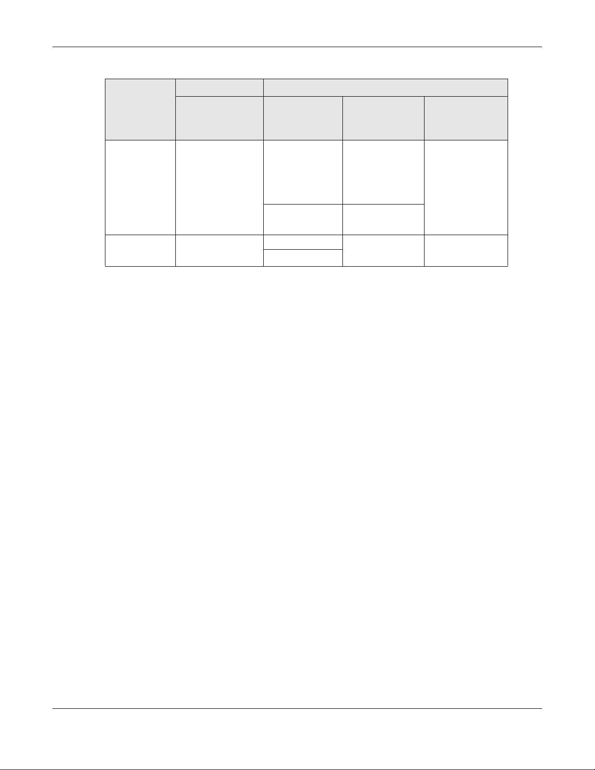
Figure 86 Network Setting > NAT > ALG
The following table describes the fields in this screen.
Table 63 Network Setting > NAT > ALG
LABEL DESCRIPTION
NAT ALG Enable this to make sure applications such as FTP and file transfer in IM applications work
SIP ALG Enable this to make sure SIP (VoIP) works correctly with port-forwarding and address-
Apply Click Apply to save your changes.
Cancel Click Cancel to restore your previously saved settings.
correctly with port-forwarding and address-mapping rules.
mapping rules.
11.7 The Address Mapping Screen
Ordering your rules is important because the Device applies the rules in the order that you specify.
When a rule matches the current packet, the Device takes the corresponding action and the
remaining rules are ignored.
Click Network Setting > NAT > Address Mapping to display the following screen.
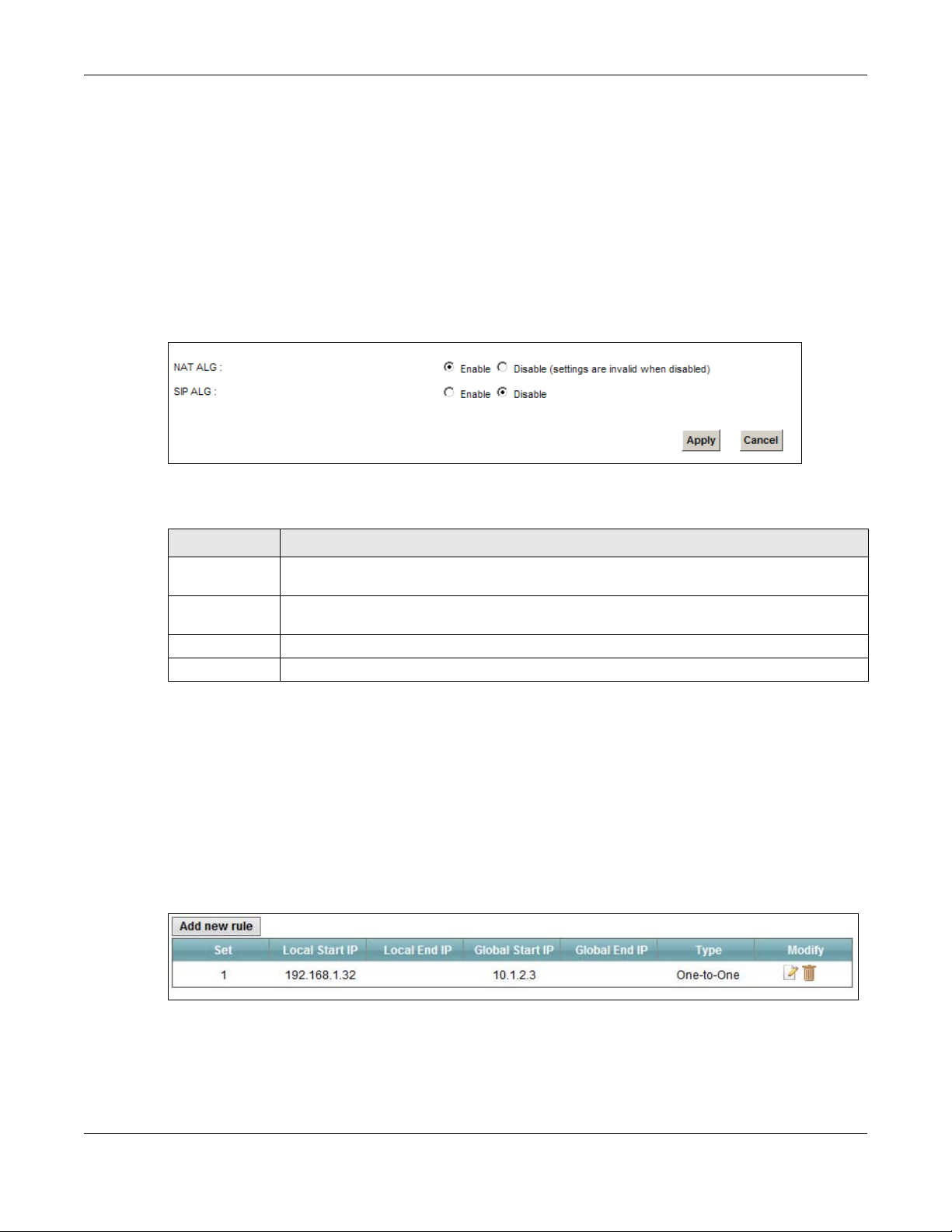
Figure 87 Network Setting > NAT > Address Mapping
VMG4381-B10A User’s Guide
190

Chapter 11 Network Address Translation (NAT)
The following table describes the fields in this screen.
Table 64 Network Setting > NAT > Address Mapping
LABEL DESCRIPTION
Add new rule Click this to create a new rule.
Set This is the index number of the address mapping set.
Local Start IP This is the starting Inside Local IP Address (ILA).
Local End IP This is the ending Inside Local IP Address (ILA). If the rule is for all local IP addresses, then
Global Start IP This is the starting Inside Global IP Address (IGA). Enter 0.0.0.0 here if you have a dynamic
Global End IP This is the ending Inside Global IP Address (IGA). This field is blank for One-to-One and
Type This is the address mapping type.
this field displays 0.0.0.0 as the Local Start IP address and 255.255.255.255 as the Local
End IP address. This field is blank for One-to-One mapping types.
IP address from your ISP. You can only do this for the Many-to-One mapping type.
Many-to-One mapping types.
One-to-One: This mode maps one local IP address to one global IP address. Note that port
numbers do not change for the One-to-one NAT mapping type.
Many-to-One: This mode maps multiple local IP addresses to one global IP address. This is
equivalent to SUA (i.e., PAT, port address translation), the Device's Single User Account
feature that previous routers supported only.
Many-to-Many: This mode maps multiple local IP addresses to shared global IP addresses.
Modify Click the Edit icon to go to the screen where you can edit the address mapping rule.
Click the Delete icon to delete an existing address mapping rule. Note that subsequent
address mapping rules move up by one when you take this action.
11.7.1 Add/Edit Address Mapping Rule
To add or edit an address mapping rule, click Add new rule or the rule’s edit icon in the Address
Mapping screen to display the screen shown next.
Figure 88 Address Mapping: Add/Edit
VMG4381-B10A User’s Guide
191

Chapter 11 Network Address Translation (NAT)
The following table describes the fields in this screen.
Table 65 Address Mapping: Add/Edit
LABEL DESCRIPTION
Type Choose the IP/port mapping type from one of the following.
One-to-One: This mode maps one local IP address to one global IP address. Note that port
numbers do not change for the One-to-one NAT mapping type.
Many-to-One: This mode maps multiple local IP addresses to one global IP address. This is
equivalent to SUA (i.e., PAT, port address translation), the Device's Single User Account
feature that previous routers supported only.
Many-to-Many: This mode maps multiple local IP addresses to shared global IP addresses.
Local Start IP
Local End IP Enter the ending Inside Local IP Address (ILA). If the rule is for all local IP addresses, then
Global Start IP Enter the starting Inside Global IP Address (IGA). Enter 0.0.0.0 here if y ou h a ve a dynamic
Global End IP Enter the ending Inside Global IP Address (IGA). This field is blank for One-to-One and
Set Select the number of the mapping set for which you want to configure.
OK Click OK to save your changes.
Cancel Click Cancel to exit this screen without saving.
Enter the starting Inside Local IP Address (ILA).
this field displays 0.0.0.0 as the Local Start IP address and 255.255.255.255 as the Local
End IP address. This field is blank for One-to-One mapping types.
IP address from your ISP. You can only do this for the Many-to-One mapping type.
Many-to-One mapping types.
11.8 Technical Reference
This part contains more information regarding NAT.
11.8.1 NAT Definitions
Inside/outside denotes where a host is located relative to the Device, for example, the computers
of your subscribers are the inside hosts, while the web servers on the Internet are the outside
hosts.
Global/local denotes the IP address of a host in a packet as the packet traverses a router, for
example, the local address refers to the IP address of a host when the packet is in the local
network, while the global address refers to the IP address of the host when the same packet is
traveling in the WAN side.
VMG4381-B10A User’s Guide
192

Note that inside/outside refers to the location of a host, while global/local refers to the IP address
of a host used in a packet. Thus, an inside local address (ILA) is the IP address of an inside host in
a packet when the packet is still in the local network, while an inside global address (IGA) is the IP
address of the same inside host when the packet is on the WAN side. The following table
summarizes this information.
Table 66 NAT Definitions
ITEM DESCRIPTION
Inside This refers to the host on the LAN.
Outside This refers to the host on the WAN.
Local This refers to the packet address (source or destination) as the packet travels on the
LAN.
Global This refers to the packet address (source or destination) as the packet travels on the
WAN.
NAT never changes the IP address (either local or global) of an outside host.
11.8.2 What NAT Does
In the simplest form, NAT changes the source IP address in a packet received from a subscriber
(the inside local address) to another (the inside global address) before forwarding the packet to the
WAN side. When the response comes back, NAT translates the destination address (the inside
global address) back to the inside local address before forwarding it to the original inside host. Note
that the IP address (either local or global) of an outside host is never changed.
Chapter 11 Network Address Translation (NAT)
The global IP addresses for the inside hosts can be either static or dynamically assigned by the ISP .
In addition, you can designate servers, for example, a web server and a telnet server, on your local
network and make them accessible to the outside world. If you do not define any servers (for Many to-One and Many-to-Many Overload mapping), NAT offers the additional benefit of firewall
protection. With no servers defined, your Device filters out all incoming inquiries, thus preventing
intruders from probing your network. For more information on IP address translation, refer to RFC
1631, The IP Network Address Translator (NAT).
VMG4381-B10A User’s Guide
193

11.8.3 How NAT Works
192.168.1.13
192.168.1.10
192.168.1.11
192.168.1.12
SA
192.168.1.10
SA
IGA1
Inside Local
IP Address
192.168.1.10
192.168.1.11
192.168.1.12
192.168.1.13
Inside Global
IP Address
IGA 1
IGA 2
IGA 3
IGA 4
NAT Table
WAN
LAN
Inside Local
Address (ILA)
Inside Global
Address (IGA)
Each packet has two addresses – a source address and a destination address. For outgoing packets,
the ILA (Inside Local Address) is the source address on the LAN, and the IGA (Inside Global
Address) is the source address on the WAN. For incoming packets, the ILA is the destination
address on the LAN, and the IGA is the destination address on the WAN. NAT maps private (local)
IP addresses to globally unique ones required for communication with hosts on other networks. It
replaces the original IP source address (and TCP or UDP source port numbers for Many-to-One and
Many-to-Many Overload NAT mapping) in each packet and then forwards it to the Internet. The
Device keeps track of the original addresses and port numbers so incoming reply packets can have
their original values restored. The following figure illustrates this.
Figure 89 How NAT Works
Chapter 11 Network Address Translation (NAT)
11.8.4 NAT Application
The following figure illustrates a possible NAT application, where three inside LANs (logical LANs
using IP alias) behind the Device can communicate with three distinct WAN networks.
VMG4381-B10A User’s Guide
194

Chapter 11 Network Address Translation (NAT)
Figure 90 NAT Application With IP Alias
Port Forwarding: Services and Port Numbers
The most often used port numbers are shown in the following table. Please refer to RFC 1700 for
further information about port numbers. Please also refer to the Supporting CD for more examples
and details on port forwarding and NAT.
Table 67 Services and Port Numbers
SERVICES PORT NUMBER
ECHO 7
FTP (File Transfer Protocol) 21
SMTP (Simple Mail Transfer Protocol) 25
DNS (Domain Name System) 53
Finger 79
HTTP (Hyper Text Transfer protocol or WWW, Web) 80
POP3 (Post Office Protocol) 110
NNTP (Network News Transport Protocol) 119
SNMP (Simple Network Management Protocol) 161
SNMP trap 162
PPTP (Point-to-Point Tunneling Protocol) 1723
Port Forwarding Example
Let's say you want to assign ports 21-25 to one FTP, Telnet and SMTP server (A in the example),
port 80 to another (B in the example) and assign a default server IP address of 192.168.1.35 to a
VMG4381-B10A User’s Guide
195

Chapter 11 Network Address Translation (NAT)
D=192.168.1.36
192.168.1.1
IP address assigned by ISP
A=192.168.1.33
B=192.168.1.34
C=192.168.1.35
third (C in the example). You assign the LAN IP addresses and the ISP assigns the WAN IP address.
The NAT network appears as a single host on the Internet.
Figure 91 Multiple Servers Behind NAT Example
VMG4381-B10A User’s Guide
196

12.1 Overview
DNS
DNS (Domain Name System) is for mapping a domain name to its corresponding IP address and
vice versa. The DNS server is extremely important because without it, you must know the IP
address of a machine before you can access it.
In addition to the system DNS server(s), each WAN interface (service) is set to have its own static
or dynamic DNS server list. You can configure a DNS static route to forward DNS queries for certain
domain names through a specific WAN interface to its DNS server(s). The Device uses a system
DNS server (in the order you specify in the Broadband screen) to resolve domain names that do
not match any DNS routing entry. After the Device receives a DNS reply from a DNS server, it
creates a new entry for the resolved IP address in the routing table.
HAPTER
C
12
Dynamic DNS Setup
Dynamic DNS
Dynamic DNS allows you to update your current dynamic IP address with one or many dynamic
DNS services so that anyone can contact you (in NetMeeting, CU-SeeMe, etc.). You can also access
your FTP server or Web site on your own computer using a domain name (for instance
myhost.dhs.org, where myhost is a name of your choice) that will never change instead of using an
IP address that changes each time you reconnect. Your friends or relatives will always be able to
call you even if they don't know your IP address.
First of all, you need to have registered a dynamic DNS account with www.dyndns.org. This is for
people with a dynamic IP from their ISP or DHCP server that would still like to have a domain name.
The Dynamic DNS service provider will give you a password or key.
12.1.1 What You Can Do in this Chapter
•Use the DNS Entry screen to view, configure, or remove DNS routes (Section 12.2 on page
198).
•Use the Dynamic DNS screen to enable DDNS and configure the DDNS settings on the Device
(Section 12.3 on page 199).
VMG4381-B10A User’s Guide
197

Chapter 12 Dynamic DNS Setup
12.1.2 What You Need To Know
DYNDNS Wildcard
Enabling the wildcard feature for your host causes *.yourhost.dyndns.org to be aliased to the same
IP address as yourhost.dyndns.org. This feature is useful if you want to be able to use, for example,
www.yourhost.dyndns.org and still reach your hostname.
If you have a private WAN IP address, then you cannot use Dynamic DNS.
12.2 The DNS Entry Screen
Use this screen to view and configure DNS routes on the Device. Click Network Setting > DNS to
open the DNS Entry screen.
Figure 92 Network Setting > DNS > DNS Entry
The following table describes the fields in this screen.
Table 68 Network Setting > DNS > DNS Entry
LABEL DESCRIPTION
Add new DNS
entry
# This is the index number of the en try.
Hostname This indicates the host name or domain name.
IP Address This indicates the IP address assigned to this computer.
Modify Click the Edit icon to edit the rule.
Click this to create a new DNS entry.
Click the Delete icon to delete an existing rule.
12.2.1 Add/Edit DNS Entry
You can manually add or edit the Device’s DNS name and IP address entry. Click Add new DNS
entry in the DNS Entry screen or the Edit icon next to the entry you want to edit. The screen
shown next appears.
VMG4381-B10A User’s Guide
198

Chapter 12 Dynamic DNS Setup
Figure 93 DNS Entry: Add/Edit
The following table describes the labels in this screen.
Table 69 DNS Entry: Add/Edit
LABEL DESCRIPTION
Host Name Enter the host name of the DNS entry.
IP Address Enter the IP address of the DNS entry.
Apply Click Apply to save your changes.
Cancel Click Cancel to exit this screen without saving.
12.3 The Dynamic DNS Screen
Use this screen to change your Device’s DDNS. Click Network Setting > DNS > Dynamic DNS.
The screen appears as shown.
Figure 94 Network Setting > DNS > Dynamic DNS
The following table describes the fields in this screen.
Table 70 Network Setting > DNS > > Dynamic DNS
LABEL DESCRIPTION
Dynamic DNS Select Enable to use dynamic DNS.
Service
Provider
Hostname Type the domain name assigned to your Device by your Dynamic DNS provider.
Username Type your user name.
Select your Dynamic DNS service provider from the drop-down list box.
You can specify up to two host names in the field separated by a comma (",").
VMG4381-B10A User’s Guide
199

Chapter 12 Dynamic DNS Setup
Table 70 Network Setting > DNS > > Dynamic DNS (continued)
LABEL DESCRIPTION
Password Type the password assigned to you.
Email If you select TZO in the Service Prov ider field, enter the user name you used to register
for this service.
Key If you select TZO in the Service Provider field, enter the password you used to register for
this service.
Apply Click Apply to save your changes.
Cancel Click Cancel to exit this screen without saving.
VMG4381-B10A User’s Guide
200

C
13.1 Overview
By default, all LAN and WAN interfaces on the Device are in the same group and can communicate
with each other. Create interface groups to have the Device assign the IP addresses in different
domains to different groups. Each group acts as an independent network on the Device. This lets
devices connected to an interface group’s LAN interfaces communicate through the interface
group’s WAN or LAN interfaces but not other WAN or LAN interfaces.
13.1.1 What You Can Do in this Chapter
The Interface Group screens let you create multiple networks on the Device (Section 13.2 on
page 201).
HAPTER
Interface Group
13
13.2 The Interface Group Screen
You can manually add a LAN interface to a new group. Alternatively, you can have the Device
automatically add the incoming traffic and the LAN interface on which traffic is received to an
interface group when its DHCP Vendor ID option information matches one listed for the interface
group.
Use the LAN screen to configure the private IP addresses the DHCP server on the Device assigns to
the clients in the default and/or user-defined groups. If you set the Device to assign IP addresses
based on the client’s DHCP Vendor ID option information, you must enable DHCP server and
configure LAN TCP/IP settings for both the default and user-defined groups. See Chapter 8 on page
133 for more information.
In the following example, the client that sends packets with the DHCP V endor ID option set to MSFT
5.0 (meaning it is a Windows 2000 DHCP client) is assigned the IP address 192.168.2.2 and uses
the WAN VDSL_PoE/ppp0.1 interface.
VMG4381-B10A User’s Guide
201

Chapter 13 Interface Group
Default: ETH 2~4
Internet
192.168.1.x/24
192.168.2.x/24
VDSL_PoE/ppp0.1
eth10.0
DHCP Vendor ID option: MSFT 5.0
Figure 95 Interface Grouping Application
Click Network Setting > Interface Grou p to open the following screen.
Figure 96 Network Setting > Interface Group
The following table describes the fields in this screen.
Table 71 Network Setting > Interface Group
LABEL DESCRIPTION
Add New
Interface Group
Group Name This shows the descriptive name of the group.
WAN Interface This shows the WAN interfaces in the group.
LAN Interfaces This shows the LAN interfaces in the group.
Criteria This shows the filtering criteria for the group.
Modify Click the Delete icon to remove the group.
Add Click this button to create a new group.
Click this button to create a new interface group.
13.2.1 Interface Group Configuration
Click the Add New Interface Group button in the Interface Group screen to open the following
screen. Use this screen to create a new interface group.
Note: An interface can belon g to only one group at a time.
VMG4381-B10A User’s Guide
202

Chapter 13 Interface Group
Figure 97 Interface Group Configuration
The following table describes the fields in this screen.
Table 72 Interface Group Configuration
LABEL DESCRIPTION
Group Name Enter a name to identify this group. You can enter up to 30 characters. You can use letters,
numbers, hyphens (-) and underscores (_). Spaces are not allowed.
WAN Interface
used in the
grouping
Grouped LAN
Interfaces
Available LAN
Interfaces
Automatically
Add Clients
With the
following DHCP
Vendor IDs
# This shows the index number of the rule.
Filter Criteria This shows the filtering criteria. The LAN interface on which the matched traffic is received
WildCard
Support
Remove Click the Remove ico n to delete this rule from the Device.
Select the WAN interface this group uses. The group can have up to one PTM interface and
up to one ATM interface.
Select None to not add a WAN interface to this group.
Select one or more LAN interfaces (Ethernet LAN, HPNA or wireless LAN) in the Available
LAN Interfaces list and use the left arrow to move them to the Grouped LAN Interfaces
list to add the interfaces to this group.
To remove a LAN or wireless LAN interface from the Grouped LAN Interfaces, use the
right-facing arrow.
Click Add to identify LAN hosts to add to the interface group by criteria such as the type of
the hardware or firmware. See Section 13.2.2 on page 204 for more information.
will belong to this group automatically.
This shows if wildcard on DHCP option 60 is enabled.
VMG4381-B10A User’s Guide
203

Chapter 13 Interface Group
Table 72 Interface Group Configuration (continued)
LABEL DESCRIPTION
Apply Click Apply to save your changes back to the Device.
Cancel Click Cancel to exit this screen without saving.
13.2.2 Interface Grouping Criteria
Click the Add button in the Interface Grouping Configuration screen to open the following
screen.
Figure 98 Interface Grouping Criteria
The following table describes the fields in this screen.
Table 73 Interface Grouping Criteria
LABEL DESCRIPTION
Source MAC
Address
DHCP Option 60Select this option and enter the Vendor Class Identifier (Option 60) of the matched traffic,
Enable
wildcard on
DHCP
option 60
option
DHCP Option 61Select this and enter the device identity of the matched traffic.
IAID Enter the Identity Association Identifier (IAID) of the device, for example, the WAN
Enter the source MAC address of the packet.
such as the type of the hardware or firmware.
Select this option to be able to use wildcards in the Vendor Class Identifier configured for
DHCP option 60.
connection index number.
VMG4381-B10A User’s Guide
204

Chapter 13 Interface Group
Table 73 Interface Grouping Criteria (continued)
LABEL DESCRIPTION
DUID type Select DUID-LLT (DUID Based on Link-layer Address Plus Time) to enter the hardware
type, a time value and the MAC address of the device.
Select DUID-EN (DUID Assigned by Vendor Based upon Enterprise Number) to enter the
vendor’s registered enterprise number.
Select DUID-LL (DUID Based on Link-layer Address) to enter the device’s hardware type
and hardware address (MAC address) in the following fields.
Select Other to enter any string that identifies the device in the DUID field.
DHCP Option
125
Enterprise
Number
Manufactur
er OUI
Product
Class
Model
Name
Serial
Number
Apply Click Apply to save your changes back to the Device.
Cancel Click Cancel to exit this screen without saving.
Select this and enter vendor specific information of the matched traffic.
Enter the vendor’s 32-bit enterprise number registered with the IANA (Internet Assigned
Numbers Authority).
Specify the vendor’s OUI (Organization Unique Identifier). It is usually the first three bytes
of the MAC address.
Enter the product class of the device.
Enter the model name of the device.
Enter the serial number of the device.
VMG4381-B10A User’s Guide
205

Chapter 13 Interface Group
VMG4381-B10A User’s Guide
206

C
14.1 Overview
The Device has a USB port used to share files via a USB memory stick or a USB hard drive. In the
USB Service screens, you can enable file-sharing server, media server, and printer server.
14.1.1 What You Can Do in this Chapter
•Use the File Sharing screen to enable file-sharing server (Section 14.2 on page 208).
•Use the Media Server screen to enable or disable the sharing of media files (Section 14.3 on
page 210).
•Use the Printer Server screen to enable the print server (Section 14.4 on page 211).
14.1.2 What You Need To Know
HAPTER
USB Service
14
The following terms and concepts may help as you read this chapter.
14.1.2.1 About File Sharing
Workgroup name
This is the name given to a set of computers that are connected on a network and share resources
such as a printer or files. Windows automatically assigns the workgroup name when you set up a
network.
Shares
When settings are set to default, each USB device connected to the Device is given a folder, called
a “share”. If a USB hard drive connected to the Device has more than one partition, then each
partition will be allocated a share. You can also configure a “share” to be a sub-folder or file on the
USB device.
File Systems
A file system is a way of storing and organizing files on your hard drive and storage device. Often
different operating systems such as Windows or Linux have different file systems. The file sharing
feature on your Device supports File Allocation Table (FAT) and FAT32.
Common Internet File System
The Device uses Common Internet File System (CIFS) protocol for its file sharing functions. CIFS
compatible computers can access the USB file storage devices connected to the Device. CIFS
VMG4381-B10A User’s Guide
207

protocol is supported on Microsoft Windows, Linux Samba and other operating systems (refer to
your systems specifications for CIFS compatibility).
14.1.2.2 About Printer Server
Print Server
This is a computer or other device which manages one or more printers, and which sends print jobs
to each printer from the computer itself or other devices.
Operating System
An operating system (OS) is the interface which helps you manage a computer. Common examples
are Microsoft Windows, Mac OS or Linux.
TCP/IP
TCP/IP (Transmission Control Protocol/ Internet Protocol) is a set of communications protocols that
most of the Internet runs on.
Chapter 14 USB Service
Port
A port maps a network service such as http to a process running on your computer, such as a
process run by your web browser. When traffic from the Internet is received on your computer, the
port number is used to identify which process running on your computer it is intended for.
Supported OSs
Your oper ating system must support TCP/IP ports for printing and be compatible with the RAW (port
9100) protocol.
The following OSs support Device’s printer sharing feature.
• Microsoft Windows 95, Windows 98 SE (Second Edition), Windows Me, Windows NT 4.0, Windows
2000, Windows XP or Macintosh OS X.
14.2 The File Sharing Screen
You can share files on a USB memory stick or hard drive connected to your Device with users on
your netw ork.
The following figure is an overview of the Device’s file server feature. Computers A and B can
access files on a USB device (C) which is connected to the Device.
VMG4381-B10A User’s Guide
208

Chapter 14 USB Service
A
B
C
Figure 99 File Sharing Overview
The Device will not be able to join the workgroup if your local area network has restrictions
set up that do not allow devices to join a workgr oup. In this case, contact your network
administrator.
14.2.1 Before You Begin
Make sure the Device is connected to your network and turned on.
1 Connect the USB device to one of the Device’s USB port. Make sure the Device is connected to your
network.
2 The Device detects the USB device and makes its contents available for browsing. If you are
connecting a USB hard drive that comes with an external power supply, make sure it is connected
to an appropriate power source that is on.
Note: If your USB device cannot be detected by the Device, see the troubleshooting for
suggestions.
Use this screen to set up file sharing using the Device. To access this screen, click Network
Setting > USB Service > File Sharing.
Figure 100 Network Setting > USB Service > File Sharing
VMG4381-B10A User’s Guide
209
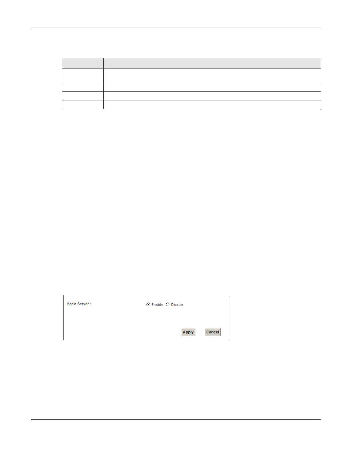
Chapter 14 USB Service
Each field is described in the following table.
Table 74 Network Setting > Home Networking > File Sharing
LABEL DESCRIPTION
File Sharing
Services
Host Name Enter the host name on the share.
Apply Click Apply to save your changes.
Cancel Click Cancel to restore your previously saved settings.
Select Enable to activate file sharing through the Device.
14.3 The Media Server Screen
The media server feature lets anyone on your network play video, music, and photos from the USB
storage device connected to your Device (without having to copy them to another computer). The
Device can function as a DLNA-compliant media server. The Device streams files to DLNA-compliant
media clients (like Windows Media Player). The Digital Living Network Alliance (DLNA) is a group of
personal computer and electronics companies that works to make products compatible in a home
network.
The Device media server enables you to:
• Publish all shares for everyone to play media files in the USB storage device connected to the
Device.
• Use hardware-based media clients like the DMA-2500 to play the files.
Note: Anyone on your network can play the media files in the published shares. No user
name and password or other form of security is used. The media server is enabled
by default with the video, photo, and music shares published.
To change your Device’s media server settings, click Network Setting > USB Service > Media
Server. The screen appears as shown.
Figure 101 Network Setting > USB Service > Media Server
VMG4381-B10A User’s Guide
210

Chapter 14 USB Service
The following table describes the labels in this menu.
Table 75 Network Setting > USB Service > Media Server
LABEL DESCRIPTION
Media Server Select Enable to have the Device function as a DLNA-compliant media server.
Enable the media server to let (DLNA-co mpli ant) media clients on your network play media
files located in the shares.
Apply Click Apply to save your changes.
Cancel Click Cancel to restore your previously saved settings.
14.4 The Printer Server Screen
The Device allows you to share a USB printer on your LAN. You can do this by connecting a USB
printer to one of the USB ports on the Device and then adding the printer on the computers
connected to your network. See Section 4.11 on page 62 for instructions on adding a printer on
your computer.
Figure 102 Sharing a USB Printer
14.4.1 Before You Begin
To configure the print server you need the following:
• Your Device must be connected to your computer and any other devices on your network. The
USB printer must be connected to your Device.
• A USB printer with the driver already installed on your computer.
•See Section 4.11 on page 62 for instructions on adding a printer on your computer.
Note: Y our printer’ s installation i nstructions ma y ask that you connect the printer to your
computer. Connect your printer to the Device instead.
Use this screen to enable or disable sharing of a USB printer via your Device.
To access this screen, click Network Setting > USB Service > Printer Server.
VMG4381-B10A User’s Guide
211

Chapter 14 USB Service
Figure 103 Network Setting > USB Service > Printer Server
The following table describes the labels in this menu.
Table 76 Network Setting > USB Service > Print Server
LABEL DESCRIPTION
Printer Server Select Enable to have the Device share a USB printer.
Printer Name Enter the name of the printer.
Make and
model
Apply Click Apply to save your changes.
Cancel Click Cancel to restore your previously saved settings.
Enter the manufacturer and model number of the printer.
VMG4381-B10A User’s Guide
212

15.1 Overview
WAN
LAN
3
4
1
2
A
This chapter shows you how to enable and configure the Device’s security settings. Use the firewall
to protect your Device and network from attacks by hackers on the Internet and control access to
it. By default the firewall:
• allows traffic that originates from your LAN computers to go to all other networks.
• blocks traffic that originates on other networks from going to the LAN.
The following figure illustrates the default firewall action. User A can initiate an IM (Instant
Messaging) session from the LAN to the WAN (1). Return traffic for this session is also allowed (2).
However other traffic initiated from the WAN is blocked (3 and 4).
Figure 104 Default Firewall Action
HAPTER
C
15
Firewall
15.1.1 What You Can Do in this Chapter
•Use the General screen to configure the security level of the firewall on the Device (Section 15.2
on page 215).
•Use the Service screen to add or remove predefined Internet services and configure firewall
rules (Section 15.3 on page 215).
•Use the Access Control screen to view and configure incoming/outgoing filtering rules (Section
15.4 on page 217).
•Use the DoS screen to activate protection against Denial of Service (DoS) attacks (Section 15.5
on page 220).
VMG4381-B10A User’s Guide
213

15.1.2 What You Need to Know
SYN Attack
A SYN attack floods a targeted system with a series of SYN packets. Each packet causes the
targeted system to issue a SYN-ACK response. While the targeted system waits for the ACK that
follows the SYN-ACK, it queues up all outstanding SYN-ACK responses on a backlog queue. SYNACKs are moved off the queue only when an ACK comes back or when an internal timer terminates
the three-way handshake. Once the queue is full, the system will ignore all incoming SYN requests,
making the system unavailable for legitimate users.
DoS
Denials of Service (DoS) attacks are aimed at devices and networks with a connection to the
Internet. Their goal is not to steal information, but to disable a device or network so users no longer
have access to network resources. The ZyXEL Device is pre-configured to automatically detect and
thwart all known DoS attacks.
DDoS
Chapter 15 Firewall
A DDoS attack is one in which multiple compromised systems attack a single target, thereby
causing denial of service for users of the targeted system.
LAND Attack
In a LAND attack, hackers flood SYN packets into the network with a spoofed source IP address of
the target system. This makes it appear as if the host computer sent the packets to itself, making
the system unavailable while the target system tries to respond to itself.
Ping of Death
Ping of Death uses a "ping" utility to create and send an IP packet that exceeds the maximum
65,536 bytes of data allowed by the IP specification. This may cause systems to crash, hang or
reboot.
SPI
Stateful Packet Inspection (SPI) tracks each connection crossing the firewall and makes sure it is
valid. Filtering decisions are based not only on rules but also context. F or example, traffic from the
WAN may only be allowed to cross the firewall in response to a request from the LAN.
VMG4381-B10A User’s Guide
214

15.2 The Firewall Screen
Use this screen to set the security level of the firewall on the Device. Firewall rules are grouped
based on the direction of travel of packets to which they apply.
Click Security > Firewall to display the General screen.
Figure 105 Security > Firewall > General
Chapter 15 Firewall
The following table describes the labels in this screen.
Table 77 Security > Firewall > General
LABEL DESCRIPTION
Firewall Select Enable to activate the firewall feature on the Device.
Easy Select Easy to allow LAN to WAN and WAN to LAN packet directions.
Medium Select Medium to allow LAN to WAN but deny WAN to LAN packet directions.
High Select High to deny LAN to WAN and WAN to LAN packet directions.
Apply Click Apply to save your changes.
Cancel Click Cancel to restore your previously saved settings.
15.3 The Service Screen
You can configure customized services and port numbers in the Service screen. For a
comprehensive list of port numbers and services, visit the IANA (Internet Assigned Number
Authority) website. See Appendix F on page 353 for some examples. This screen is not applicable to
VMG4381.
Click Security > Firewall > Service to display the following screen.
Figure 106 Security > Firewall > Service
VMG4381-B10A User’s Guide
215

The following table describes the labels in this screen.
Table 78 Security > Firewall > Service
LABEL DESCRIPTION
Add new
service entry
Name This is the name of your customized servic e.
Description This is the description of your customized service.
Ports/Protocol
Number
Modify Click the Edit icon to edit the entry.
Click this to add a new service.
This shows the IP protocol (TCP, UDP, ICMP, or TCP/UDP) and the port number or range
of ports that defines your customized service. Other and the protocol number displays if the
service uses another IP protocol.
Click the Delete icon to remove this entry.
15.3.1 Add/Edit a Service
Use this screen to add a customized service rule that you can use in the firewall’s ACL rule
configuration. Click Add new service entry or the edit icon next to an existing service rule in the
Service screen to display the following screen.
Chapter 15 Firewall
Figure 107 Service: Add/Edit
VMG4381-B10A User’s Guide
216

Chapter 15 Firewall
The following table describes the labels in this screen.
Table 79 Service: Add/Edit
LABEL DESCRIPTION
Protocol Choose the IP protocol (TCP, UDP, ICMP, or Other) that defines your customized port from
Source/
Destination Port
Protocol
Number
Add Click this to add the protocol to the Rule List below.
Rule List
Protocol This is the IP port (TCP, UDP, ICMP, or Other) that defines your customized port.
Ports/Protocol
Number
Modify Click the Delete icon to remove the rule.
Service Name Enter a unique name (up to 32 printable English keyboard characters, including spaces) for
Service
Description
Apply Click Apply to save your changes.
Cancel Click Cancel to exit this screen without saving.
the drop-down list box. Select Other to be able to enter a protocol number.
These fields are displayed if you select TCP or UDP as the IP port.
Select Single to specify one port only or Range to specify a span of ports that define your
customized service. If you select Any, the service is applied to all ports.
Type a single port number or the range of port numbers that define your customized
service.
This field is displayed if you select Other as the protocol.
Enter the protocol number of your customized port.
For TCP, UDP, ICMP, or TCP/UDP protocol rules this shows the port number or range that
defines the custom service. For other IP protocol rules this shows the protocol number.
your customized port.
Enter a description for your customized port.
15.4 The Access Control Screen
Click Security > Firewall > Access Control to display the following screen. This screen displays a
list of the configured incoming or outgoing filtering rules.
Figure 108 Security > Firewall > Access Control
VMG4381-B10A User’s Guide
217

Chapter 15 Firewall
The following table describes the labels in this screen.
Table 80 Security > Firewall > Access Control
LABEL DESCRIPTION
DoS Protection DoS (Denial of Service) attacks can flood your Internet connection with invalid packets and
Add new ACL
rule
# This is the index number of the entry.
Name This displays the name of the rule.
Src IP This displays the source IP addresses to which this rule applies. Please note that a blank
Dst IP This displays the destination IP addresses to which this rule applies. Please note that a
Service This displays the transport layer protocol that defines the serv ice and the direction of tr affic
Action This field displays whether the rule silently discards packets (DROP), discards packets and
Modify Click the Edit icon to edit the rule.
connection requests, using so much bandwidth and so many resources that Internet access
becomes unavailable.
Select the Enable check box to enable protection against DoS attacks.
Click this to go to add a filter rule for incoming or outgoing IP traffic.
source address is equivalent to Any.
blank destination address is equivalent to Any.
to which this rule applies.
sends a TCP reset packet or an ICMP destination-unreachable message to the sender
(REJECT) or allows the passage of packets (ACCEPT).
Click the Delete icon to delete an existing rule. Note that subsequent rules move up by one
when you take this action.
Click the Move To icon to change the order of the rule. Enter the number in the # field.
15.4.1 Add/Edit an ACL Rule
Click Add new ACL rule or the Edit icon next to an existing ACL rule in the Access Control
screen. The following screen displays.
VMG4381-B10A User’s Guide
218

Figure 109 Access Control: Add/Edit
Chapter 15 Firewall
The following table describes the labels in this screen.
Table 81 Access Control: Add/Edit
LABEL DESCRIPTION
Filter Name Enter a descriptive name of up to 16 alphanumeric characters, not including spaces,
underscores, and dashes.
You must enter the filter name to add an ACL rule. This field is read-only if you are editing
the ACL rule.
Order Select the order of the ACL rule.
Select Source
Device
Source IP
Address
Select
Destination
Device
Destination IP
Address
IP Type Select whether your IP type is IPv4 or IPv6.
Select Protocol Select the transport layer protocol that defines your customized port from the drop-down
Select the source device to which the ACL rule applies. If you select Specific IP Address,
enter the source IP address in the field below.
Enter the source IP address.
Select the destination device to which th e ACL rule applies. If you select Specific IP
Address, enter the destiniation IP address in the field below.
Enter the destination IP address.
list box. The specific protocol rule sets yo u add in the Security > Firewall > Service >
Add screen display in this list.
If you want to configure a customized protocol, select Specific Service.
VMG4381-B10A User’s Guide
219

Chapter 15 Firewall
Table 81 Access Control: Add/Edit (continued)
LABEL DESCRIPTION
Protocol This field is displayed only when you select Specific Protocol in Select Protocol.
Choose the IP port (TCP/UDP, TCP, UDP, ICMP, or ICMPv6) that defines your customized
port from the drop-down list box.
Custom Source
Port
Custom
Destination Port
Policy Use the drop-down list box to select whether to discard (DROP), deny and send an ICMP
Direction Use the drop-down list box to select the direction of traffic to which this rule applies.
Enable Rate
Limit
Scheduler Rules Select a schedule rule for this ACL rule form the drop-down list box. You can configure a
Apply Click Apply to save your changes.
Cancel Click Cancel to exit this screen without saving.
This field is displayed only when you select Specific Protocol in Select Protocol.
Enter a single port number or the range of port numbers of the source.
This field is displayed only when you select Specific Protocol in Select Protocol.
Enter a single port number or the range of port numbers of the destination.
destination-unreachable message to the sender of (REJECT) or allow the passage of
(ACCEPT) packets that match this rule.
Select this check box to set a limit on the upstream/downstream transmission rate for the
specified protocol.
Specify how many packets per minute or second the transmission rate is.
new schedule rule by click Add New Rule. This will bring you to the Security > Scheduler
Rules screen.
15.5 The DoS Screen
DoS (Denial of Service) attacks can flood your Internet connection with invalid packets and
connection requests, using so much bandwidth and so many resources that Internet access
becomes unavailable.
Use the DoS screen to activate protection against DoS attacks. Click Security > Firewall > DoS
to display the following screen.
Figure 110 Security > Firewall > DoS
VMG4381-B10A User’s Guide
220

Chapter 15 Firewall
The following table describes the labels in this screen.
Table 82 Security > Firewall > DoS
LABEL DESCRIPTION
DoS Protection
Blocking
Deny Ping
Response
Apply Click Apply to save your changes.
Cancel Click Cancel to exit this screen without saving.
Select Enable to enable protection against DoS attacks.
Select Enable to block ping request packets.
VMG4381-B10A User’s Guide
221

Chapter 15 Firewall
VMG4381-B10A User’s Guide
222

16.1 Overview
You can configure the Device to permit access to clients based on their MAC addresses in the MAC
Filter screen. This applies to wired and wireless connections. Every Ethernet device has a unique
MAC (Media Access Control) address. The MAC address is assigned at the factory and consists of six
pairs of hexadecimal characters, for example, 00:A0:C5:00:00:02. You need to know the MAC
addresses of the devices to configure this screen.
HAPTER
C
16
MAC Filter
VMG4381-B10A User’s Guide
223

Chapter 16 MAC Filter
16.2 The MAC Filter Screen
Use this screen to allow wireless and LAN clients access to the Device. Click Security > MAC Filter.
The screen appears as shown.
Figure 111 Security > MAC Filter
The following table describes the labels in this screen.
Table 83 Security > MAC Filter
LABEL DESCRIPTION
MAC Address Filter Select Enable to activate the MAC filter function.
Set This is the index number of the MAC address.
Allow Select Allow to permit access to the Device. MAC addresses not listed will be denied
access to the Device.
If you clear this, the MAC Address field for this set clears.
Host name Enter the host name of the wireless or LAN clients that are allowed access to the
Device.
MAC Address Enter the MAC addresses of the wireless or LAN clients that are allowed access to the
Device in these address fields . E nte r the MAC addresses in a valid MAC address format,
that is, six hexadecimal character pairs, for example, 12:34:56:78:9a:bc.
VMG4381-B10A User’s Guide
224

Chapter 16 MAC Filter
Table 83 Security > MAC Filter (continued)
LABEL DESCRIPTION
Apply Click Apply to save your changes.
Cancel Click Cancel to restore your previously saved settings.
VMG4381-B10A User’s Guide
225

Chapter 16 MAC Filter
VMG4381-B10A User’s Guide
226

HAPTER
C
17.1 Overview
Parental control allows you to block web sites with the specific URL. You can also define time
periods and days during which the Device performs parental control on a specific user.
17.2 The Parental Control Screen
Use this screen to enable parental control, view the parental control rules and schedules.
Click Security > Parental Control to open the following screen.
Figure 112 Security > Parental Control
17
Parental Control
The following table describes the fields in this screen.
Table 84 Security > Parental Control
LABEL DESCRIPTION
Parental
Control
Add new PCP Click this if you want to configure a new parental control rule.
# This shows the index number of the rule.
Status This indicates whether the rule is active or not.
PCP Name This shows the name of the rule.
Home Network
User (MAC)
Select Enable to activate parental control.
A yellow bulb signifies that this rule is activ e. A gra y bulb signifies that this rule is not acti ve.
This shows the MAC address of the LAN user’s computer to which this rule applies.
VMG4381-B10A User’s Guide
227

Chapter 17 Parental Control
Table 84 Security > Parental Control (continued)
LABEL DESCRIPTION
Internet Access
Schedule
Network
Service
Website Block This shows whether the website block is configured. If not, None will be shown.
Modify Click the Edit icon to go to the screen where you can edit the rule.
Apply Click Apply to save your changes.
Cancel Click Cancel to restore your previously saved settings.
This shows the day(s) and time on which parental control is enabled.
This shows whether the network service is configured. If not, None will be shown.
Click the Delete icon to delete an existing rule.
17.2.1 Add/Edit a Parental Control Rule
Click Add new PCP in the Parental Control screen to add a new rule or click the Edit icon next to
an existing rule to edit it. Use this screen to configure a restricted access schedule and/or URL
filtering settings to block the users on your network from accessing certain web sites.
Figure 113 Parental Control Rule: Add/Edit
VMG4381-B10A User’s Guide
228

Chapter 17 Parental Control
The following table describes the fields in this screen.
Table 85 Parental Control Rule: Add/Edit
LABEL DESCRIPTION
General
Active Select the checkbox to activate this parental control rule.
Parental
Control Profile
Name
Home Network
User
Internet Access Schedule
Day Select check boxes for the days that you want the Device to perform parental control.
Time Drag the time bar to define the time that the LAN user is allowed access.
Network Service
Network
Service Setting
Add new
service
# This shows the index number of the rule. Select th e checkbox next to the rule to activate it.
Service Name This shows the name of the rule.
Protocol:Port This shows the protocol and the port of the rule.
Modify Click the Edit icon to go to the screen where you can edit the rule.
Enter a descriptive name for the rule.
Select the LAN user that you want to apply this rule to from the drop-down list box. If you
select Custom, enter the LAN user’s MAC address. If you select All, the rule applies to all
LAN users.
If you select Block, the Device prohibits the users from viewing the Web sites with the URLs
listed below.
If you select Allow, the Device blocks access to all URLs except ones listed below.
Click this to show a screen in which you can add a new service rule. You can configure the
Service Name, Protocol, and Name of the new rule.
Click the Delete icon to delete an existing rule.
Blocked Site/
URL Keyword
Apply Click this button to save your settings back to the Device.
Cancel Click Cancel to restore your previously saved settings.
Click Add to show a screen to enter the URL of web site or URL keyword to which the Device
blocks access. Click Delete to remove it.
VMG4381-B10A User’s Guide
229

Chapter 17 Parental Control
VMG4381-B10A User’s Guide
230

HAPTER
C
18.1 Overview
You can define time periods and days during which the Device performs scheduled rules of certain
features (such as Firewall Access Control, Parental Control) on a specific user in the Scheduler Rules
screen.
18.2 The Scheduler Rules Screen
Use this screen to view, add, or edit time schedule rules.
Click Security > Scheduler Rules to open the following screen.
18
Scheduler Rules
Figure 114 Security > Scheduler Rules
The following table describes the fields in this screen.
Table 86 Security > Scheduler Rules
LABEL DESCRIPTION
Add new rule Click this to create a new rule.
# This is the index number of the entry.
Rule Name This shows the name of the rule.
Day This shows the day(s) on which this rule is enabled.
Time This shows the period of time on which this rule is enabled.
Description This shows the description of this rule.
Modify Click the Edit icon to edit the schedule.
Click the Delete icon to delete a scheduler rule.
Note: You cannot delete a scheduler rule once it is applie d to a certain feature.
18.2.1 Add/Edit a Schedule
Click the Add button in the Scheduler Rules screen or click the Edit icon next to a schedule rule
to open the following screen. Use this screen to configure a restricted access schedule for a specific
user on your network.
VMG4381-B10A User’s Guide
231

Chapter 18 Scheduler Rules
Figure 115 Scheduler Rules: Add/Edit
The following table describes the fields in this screen.
Table 87 Scheduler Rules: Add/Edit
LABEL DESCRIPTION
Rule Name Enter a name (up to 31 printable English keyboard characters, not including spaces) for this
schedule.
Day Select check boxes for the days that you want the Device to perform this scheduler rule.
Time if Day
Range
Description Enter a description for this scheduler rule.
Apply Click Apply to save your changes.
Cancel Click Cancel to exit this screen without saving.
Enter the time period of each day, in 24-hour format, during which parental control will be
enforced.
VMG4381-B10A User’s Guide
232

C
19.1 Overview
The Device can use certificates (also called digital IDs) to authenticate users. Certificates are based
on public-private key pairs. A certificate contains the certificate owner’s identity and public key.
Certificates provide a way to exchange public keys for use in authentication.
19.1.1 What You Can Do in this Chapter
•The Local Certificates screen lets you generate certification requests and import the Device's
CA-signed certificates (Section 19.4 on page 237).
•The Trusted CA screen lets you save the certificates of trusted CAs to the Device (Section 19.4
on page 237).
HAPTER
Certificates
19
19.2 What You Need to Know
The following terms and concepts may help as you read through this chapter.
Certification Authority
A Certification Authority (CA) issues certificates and guarantees the identity of each certificate
owner. There are commercial certification authorities like CyberTrust or VeriSign and government
certification authorities. The certification authority uses its private key to sign certificates. Anyone
can then use the certification authority's public key to v erify the certificates. Y ou can use the Device
to generate certification requests that contain identifying information and public keys and then send
the certification requests to a certification authority.
19.3 The Local Certificates Screen
Click Security > Certificates to open the Local Certificates screen. This is the Device’ s summary
list of certificates and certification requests.
VMG4381-B10A User’s Guide
233

Chapter 19 Certificates
Figure 116 Security > Certificates > Local Certificates
The following table describes the labels in this screen.
Table 88 Security > Certificates > Local Certificates
LABEL DESCRIPTION
Private Key is
protected by a
password?
Browse... Click this to find the certificate file you want to upload.
Import Certificate Click this button to save the certificate that you have enrolled from a certification
Create Certificate
Request
Current File This field displays the name used to identify this certificate. It is recommended that you
Subject This field displays identifying information about the certificate’s owner, such as CN
Issuer This field displays identifying information about the certificate’s issuing certification
Valid From This field displays the date that the certificate becomes applicable. The text displays in
Valid To This field displays the date that the certificate expires. The text displays in red and
Modify Click the View icon to open a screen with an in-depth list of information about the
Select the checkbox and enter the private key into the text box to store it on the Device.
The private key should not exceed 63 ASCII characters (not including spaces).
authority from your computer to the Device.
Click this button to go to the screen where you can have the Device generate a
certification request.
give each certificate a unique name.
(Common Name), OU (Organizational Unit or department), O (Organization or company)
and C (Country). It is recommended that each certificate have unique subject
information.
authority, such as a common name, organizational unit or department, organization or
company and country.
red and includes a Not Yet Valid! message if the certificate has not yet become
applicable.
includes an Expiring! or Expired! message if the certificate is about to expire or has
already expired.
certificate (or certification request).
For a certification request, click Load Signed to import the signed certificate.
Click the Remove icon to delete the certificate (or certification request). You cannot
delete a certificate that one or more features is configured to us e.
19.3.1 Create Certificate Request
Click Security > Certificates > Local Certificates and then Create Certificate Request to
open the following screen. Use this screen to have the Device generate a certification request.
VMG4381-B10A User’s Guide
234

Chapter 19 Certificates
Figure 117 Create Certificate Request
The following table describes the labels in this screen.
Table 89 Create Certificate Request
LABEL DESCRIPTION
Certificate
Name
Common Name Select Auto to have the Device configure this field automatically. Or select Customize to
Type up to 63 ASCII characters (not including spaces) to identify this certificate.
enter it manually.
T ype the IP address (in dotted decimal notation), domain name or e-mail address in the field
provided. The domain name or e-mail address can be up to 63 ASCII characters. The
domain name or e-mail address is for identification purposes only and can be any string.
Organization
Name
State/Province
Name
Country/Region
Name
Apply Click Apply to save your changes.
Cancel Click Cancel to exit this screen without saving.
Type up to 63 characters to identify the company or group to which the certificate owner
belongs. You may use any character, including spaces, but the Device drops trailing spaces.
Type up to 32 characters to identify the state or province where the certificate owner is
located. You may use any character, including spaces, but the Device drops trailing spaces.
Select a country to identify the nation where the certificate owner is located.
After you click Apply, the following screen displays to notify you that you need to get the certificate
request signed by a Certificate Authority. If you already have, click Load_Signed to import the
signed certificate into the Device. Otherwise click Back to return to the Local Certificates screen.
VMG4381-B10A User’s Guide
235

Chapter 19 Certificates
Figure 118 Certificate Request Created
19.3.2 Load Signed Certificate
After you create a certificate request and have it signed by a Certificate Authority, in the Local
Certificates screen click the certificate request’s Load Signed icon to import the signed certificate
into the Device.
Note: You must remove any spaces from the certificate’s filename before you can import
it.
Figure 119 Load Signed Certificate
VMG4381-B10A User’s Guide
236

Chapter 19 Certificates
The following table describes the labels in this screen.
Table 90 Load Signed Certificate
LABEL DESCRIPTION
Certificate
Name
Certificate Copy and paste the signed certificate into the text box to store it on the Device.
Apply Click Apply to save your changes.
Cancel Click Cancel to exit this screen without saving.
This is the name of the signed certificate.
19.4 The Trusted CA Screen
Click Security > Certificates > Trusted CA to open the following screen. This screen displays a
summary list of certificates of the certification authorities that you have set the Device to accept as
trusted. The Device accepts any valid certificate signed by a certification authority on this list as
being trustworthy; thus you do not need to import any certificate that is signed by one of these
certification authorities.
Figure 120 Security > Certificates > Trusted CA
The following table describes the fields in this screen.
Table 91 Security > Certificates > Tr usted CA
LABEL DESCRIPTION
Import
Certificate
# This is the index number of the entry.
Name This field displays the name used to identify this certificate.
Subject This field displays information that identifies the owner of the certificate, such as Common
Type This field displays general information about the certificate. ca means that a Certification
Modify Click the View icon to open a screen with an in-depth list of information about the
Click this button to open a screen where you can save the certificate of a certification
authority that you trust to the De vice.
Name (CN), OU (Organizational Unit or department), Organization (O), State (ST) and
Country (C). It is recommended that each certificate have unique subject information.
Authority signed the certificate.
certificate (or certification request).
Click the Remove button to delete the certificate (or certification request). You cannot
delete a certificate that one or more features is configured to use.
19.4.1 View Trusted CA Certificate
Click the View icon in the Trusted CA screen to open the following screen. Use this screen to view
in-depth information about the certification authority’s certificate.
VMG4381-B10A User’s Guide
237

Chapter 19 Certificates
Figure 121 Trusted CA: View
The following table describes the fields in this screen.
Table 92 Trusted CA: View
LABEL DESCRIPTION
Name This field displays the identifying name of this certificate.
Type This field displays general information about the certificate. ca means that a Certification
Authority signed the certificate.
Subject This field displays information that identifies the owner of the certificate, such as Common
Certificate This read-only text box displays the certificate in Privacy Enhanced Mail (PEM) format. PEM
Back Click Back to return to the previous screen.
Name (CN), Organizational Unit (OU), Organization (O) and Country (C).
uses base 64 to convert the binary certificate into a printable form.
You can cop y and past e the ce rtific ate in to an e-ma il to se nd to frie nds or col lea gues or yo u
can copy and paste the certificate into a text editor and save the file on a management
computer for later distribution (via floppy disk for example).
19.4.2 Import Trusted CA Certificate
Click the Import Certificate button in the Trusted CA screen to open the following screen. The
Device trusts any valid certificate signed by any of the imported trusted CA certificates.
VMG4381-B10A User’s Guide
238

Chapter 19 Certificates
Figure 122 Trusted CA: Import Certificate
The following table describes the fields in this screen.
Table 93 Trusted CA: Import Certificate
LABEL DESCRIPTION
Certificate File
Path
Enable Trusted
CA for 802.1x
Authentication
Certificate Copy and paste the certificate into the text box to store it on the Device.
OK Click OK to save your changes.
Cancel Click Cancel to exit this screen without saving.
Type in the location of the certificate you want to upload in this field or click Browse ... to
find it.
If you select this checkbox, the trusted CA will be used for 802.1x authentication. The
selected trusted CA will be displayed in the Network Setting > Broadband > 802.1x:
Edit screen.
VMG4381-B10A User’s Guide
239

Chapter 19 Certificates
VMG4381-B10A User’s Guide
240

C
20.1 Overview
The web configurator allows you to choose which categories of events and/or alerts to have the
Device log and then display the logs or have the Device send them to an administrator (as e-mail)
or to a syslog server.
20.1.1 What You Can Do in this Chapter
•Use the System Log screen to see the system logs (Section 20.2 on page 242).
•Use the Security Log screen to see the security-related logs for the categories that you select
(Section 20.3 on page 243).
20.1.2 What You Need To Know
HAPTER
20
Log
The following terms and concepts may help as you read this chapter.
Alerts and Logs
An alert is a type of log that warrants more serious attention. They include system errors, attacks
(access control) and attempted access to blocked web sites. Some categories such as System
Errors consist of both logs and alerts. You may differentiate them by their color in the View Log
screen. Alerts display in red and logs display in black.
Syslog Overview
The syslog protocol allows devices to send event notification messages across an IP network to
syslog servers that collect the event messages. A syslog-enabled device can generate a syslog
message and send it to a syslog server.
Syslog is defined in RFC 3164. The RFC defines the packet format, content and system log related
information of syslog messages. Each syslog message has a facility and severity level. The syslog
facility identifies a file in the syslog server. Refer to the documentation of your syslog program for
details. The following table describes the syslog severity levels.
Table 94 Syslog Severity Levels
CODE SEVERITY
0 Emergency: The system is unusable.
1 Alert: Action must be taken immediately.
2 Critical: The system condition is critical.
3 Error: There is an error condition on the system.
4 Warning: There is a warning condition on the sy stem.
VMG4381-B10A User’s Guide
241

Chapter 20 Log
Table 94 Syslog Severity Levels
CODE SEVERITY
5 Notice: There is a normal but significant condition on the system.
6 Informational: The syslog contains an informational message.
7 Debug: The message is intended for debug-level purposes.
20.2 The System Log Screen
Use the System Log screen to see the system logs. Click System Monitor > Log to open the
System Log screen.
Figure 123 System Monitor > Log > System Log
The following table describes the fields in this screen.
Table 95 System Monitor > Log > System Log
LABEL DESCRIPTION
Level Sele ct a severity level from the drop-down l ist box. This filters search results according to
the severity level you have selected. When you select a severity, the Device searches
through all logs of that severity or higher.
Category Select the type of logs to display.
Clear Log Clic k this to delete all the logs.
Refresh Click this to renew the log screen.
Export Log Click this to export the selected log(s).
Email Log Now Click this to send the log file(s) to the E-mail address you speci fy in the Maintenance >
Logs Setting screen.
System Log
# Th is field is a sequential value and is not associated with a specific entry.
Time This field displays the time the log was recorded.
Facility The log facility allows you to send logs to different files in the syslog server. Refer to the
documentation of your syslog program for more details.
Level This field displays the severity level of the logs that the device is to send to this syslog
Messages This field states the reason for the log.
server.
VMG4381-B10A User’s Guide
242

Chapter 20 Log
20.3 The Security Log Screen
Use the Security Log screen to see the security-related logs for the categories that you select.
Click System Monitor > Log > Security Log to open the following screen.
Figure 124 System Monitor > Log > Security Log
The following table describes the fields in this screen.
Table 96 System Monitor > Log > Security Log
LABEL DESCRIPTION
Level Sele ct a severity level from the drop-down l ist box. This filters search results according to
the severity level you have selected. When you select a severity, the Device searches
through all logs of that severity or higher.
Category Select the type of logs to display.
Clear Log Clic k this to delete all the logs.
Refresh Click this to renew the log screen.
Export Log Click this to export the selected log(s).
Email Log Now Click this to send the log file(s) to the E-mail address you speci fy in the Maintenance >
Logs Setting screen.
# Th is field is a sequential value and is not associated with a specific entry.
Time This field displays the time the log was recorded.
Facility The log facility allows you to send logs to different files in the syslog server. Refer to the
documentation of your syslog program for more details.
Level This field displays the severity level of the logs that the device is to send to this syslog
Messages This field states the reason for the log.
server.
VMG4381-B10A User’s Guide
243

Chapter 20 Log
VMG4381-B10A User’s Guide
244

C
21.1 Overview
Use the Traffic Status screens to look at network traffic status and statistics of the WAN and LAN
interfaces.
21.1.1 What You Can Do in this Chapter
•Use the WAN screen to view the WAN traffic statistics (Section 21.2 on page 245).
•Use the LAN screen to view the LAN traffic statistics (Section 21.3 on page 246).
21.2 The WAN Status Screen
HAPTER
Traffic Status
21
Click System Monitor > Traffic Status to open the WAN screen. The figure in this screen shows
the number of bytes received and sent on the Device.
Figure 125 System Monitor > Traffic Status > WAN
VMG4381-B10A User’s Guide
245

Chapter 21 Traffic Status
The following table describes the fields in this screen.
Table 97 System Monitor > Traffic Status > WAN
LABEL DESCRIPTION
Connected
Interface
Packets Sent
Data This indicates the number of transmitted packets on this interface.
Error This indicates the number of frames with errors transmitted on this interface.
Drop This indicates the number of outgoin g packets dropped on this interface.
Packets Received
Data This indicates the number of received packets on this interface.
Error This indicates the number of frames with errors received on this interface.
Drop This indicates the number of received packets dropped on this interface.
more...hide
more
Disabled
Interface
Packets Sent
Data This indicates the number of transmitted packets on this interface.
Error This indicates the number of frames with errors transmitted on this interface.
Drop This indicates the number of outgoin g packets dropped on this interface.
Packets Received
Data This indicates the number of received packets on this interface.
Error This indicates the number of frames with errors received on this interface.
Drop This indicates the number of received packets dropped on this interface.
This shows the name of the WAN interface that is currently connected.
Click more... to show more information. Click hide more to hide them.
This shows the name of the WAN interface that is currently disconnected.
21.3 The LAN Status Screen
Click System Monitor > Traffic Status > LAN to open the following screen. The figure in this
screen shows the interface that is currently connected on the Device.
Figure 126 System Monitor > Traffic Status > LAN
The following table describes the fields in this screen.
Table 98 System Monitor > Traffic Status > LAN
LABEL DESCRIPTION
Refresh Interval Select how often you want the Device to update this screen.
Interface This shows the LAN or WLAN interface.
Bytes Sent This indicates the number of bytes transmitted on this interface.
VMG4381-B10A User’s Guide
246

Chapter 21 Traffic Status
Table 98 System Monitor > Traffic Status > LAN (continued)
LABEL DESCRIPTION
more...hide
more
Interface This shows the LAN or WLAN interface.
Sent (Packets)
Data This indicates the number of transmitted packets on this interface.
Error This indicates the number of frames with errors transmitted on this interface.
Drop This indicates the number of outgoing packets dropped on this interface.
Received (Packets)
Data This indicates the number of received packets on this interface.
Error This indicates the number of frames with errors received on this interface.
Drop This indicates the number of received packets dropped on this interface.
Click more... to show more information. Click hide more to hide them.
VMG4381-B10A User’s Guide
247

Chapter 21 Traffic Status
VMG4381-B10A User’s Guide
248

22.1 Overview
Address Resolution Protocol (ARP) is a protocol for mapping an Internet Protocol address (IP
address) to a physical machine address, also known as a Media Access Control or MAC address, on
the local area network.
An IP (version 4) address is 32 bits long. In an Ethernet LAN, MAC addresses are 48 bits long. The
ARP Table maintains an association between each MAC address and its corresponding IP address.
22.1.1 How ARP Works
When an incoming packet destined for a host device on a local area network arrives at the device,
the device's ARP program looks in the ARP Table and, if it finds the address, sends it to the device.
HAPTER
C
22
ARP Table
If no entry is found for the IP address, ARP broadcasts the request to all the devices on the LAN.
The device fills in its own MAC and IP address in the sender address fields, and puts the known IP
address of the target in the target IP address field. In addition, the device puts all ones in the target
MA C field (FF.FF.FF.FF.F F.FF is th e Ethernet broadc ast address). The replying device (which is either
the IP address of the device being sought or the router that knows the way) replaces the broadcast
address with the target's MAC address, swaps the sender and target pairs, and unicasts the answer
directly back to the requesting machine. ARP updates the ARP Table for future reference and then
sends the packet to the MAC address that replied.
22.2 ARP Table Screen
Use the ARP table to view IP-to-MAC address mapping(s). To open this screen, click System
Monitor > ARP Table.
Figure 127 System Monitor > ARP Table
The following table describes the labels in this screen.
Table 99 System Monitor > ARP Table
LABEL DESCRIPTION
# This is the ARP table entry number.
IP Address This is the learned IP address of a device connected to a port.
VMG4381-B10A User’s Guide
249

Chapter 22 ARP Table
Table 99 System Monitor > ARP Table (continued)
LABEL DESCRIPTION
MAC Address This is the MAC address of the device with the listed IP address.
Device This is the type of interface used by the device. You can click on the device type to go to its
configuration screen.
VMG4381-B10A User’s Guide
250
 Loading...