

Chapter 11 Network Address Translation (NAT)
Table 54 Port Forwarding: Add/Edit (continued)
LABEL DESCRIPTION
End Port Enter the last port of the original destination port range.
To forward only one port, enter the port number in the Start Port field above and then
enter it again in this field.
To forward a series of ports, enter the last port number in a series that begins with the port
number in the Start Port field above.
Translation
Start Port
Translation End
Port
Server IP
Address
Protocol Select the protocol supported by this virtual server. Choices are TCP, UDP, or TCP/UDP.
OK Click OK to save your changes.
Cancel Click Cancel to exit this screen without saving.
This shows the port number to which you want the Device to translate the incoming port.
For a range of ports, enter the first number of the range to which you want the incoming
ports translated.
This shows the last port of the translated port range.
Enter the inside IP address of the virtual server here.
11.3 The Applications Screen
This screen provides a summary of all NAT applications and their configuration. In addition, this
screen allows you to create new applications and/or remove existing ones.
To access this screen, click Network Setting > NAT > Applications. The following screen
appears.
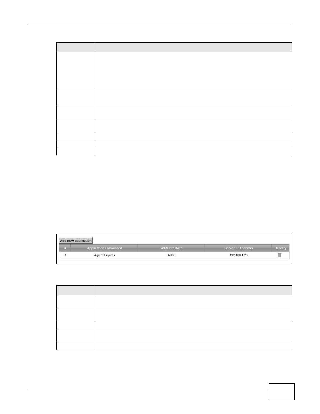
Figure 78 Network Setting > NAT > Applications
The following table describes the labels in this screen.
Table 55 Network Setting > NAT > Applications
LABEL DESCRIPTION
Add new
application
Application
Forwarded
WAN Interface This field shows the WAN interface through which the service is forwarded.
Server IP
Address
Modify Click the Delete icon to delete the rule.
Click this to add a new NAT application rule.
This field shows the type of application that the service forwards.
This field displays the destination IP address for the service.
VMG4380-B10A / VMG4325-B10A User’s Guide
181
Chapter 11 Network Address Translation (NAT)
VMG4380-B10A / VMG4325-B10A User’s Guide
182
11.3.1 Add New Application
This screen lets you create new NAT application rules. Click Add new application in the
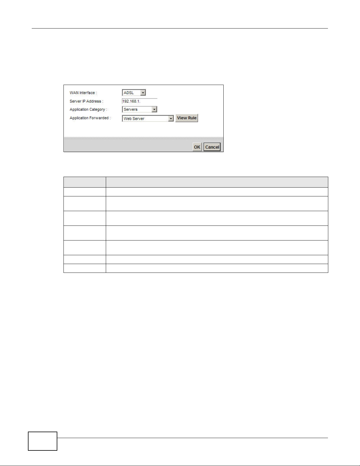
Applications screen to open the following screen.
Figure 79 Applications: Add
The following table describes the labels in this screen.
11.4 The Port Triggering Screen
Some services use a dedicated range of ports on the client side and a dedicated range of ports on
the server side. With regular port forwarding you set a forwarding port in NAT to forward a service
(coming in from the server on the WAN) to the IP address of a computer on the client side (LAN).
The problem is that port forwarding only forwards a service to a single LAN IP address. In order to
use the same service on a different LAN computer, you have to manually replace the LAN
computer's IP address in the forwarding port with another LAN computer's IP address.
Trigger port forwarding solves this problem by allowing computers on the LAN to dynamically take
turns using the service. The Device records the IP address of a LAN computer that sends traffic to
the WAN to request a service with a specific port number and protocol (a "trigger" port). When the
Device's WAN port receives a response with a specific port number and protocol ("open" port), the
Device forwards the traffic to the LAN IP address of the computer that sent the request. After that
computer’s connection for that service closes, another computer on the LAN can use the service in
the same manner. This way you do not need to configure a new IP address each time you want a
different LAN computer to use the application.
Table 56 Applications: Add
LABEL DESCRIPTION
WAN Interface Select the WAN interface that you want to apply this NAT rule to.
Server IP
Address
Enter the inside IP address of the application here.
Application
Category
Select the category of the application from the drop-down list box.
Application
Forwarded
Select a service from the drop-down list box and the Device automatically configures the
protocol, start, end, and map port number that define the service.
View Rule Click this to display the configuration of the service that you have chosen in Application
Fowarded.
OK Click OK to save your changes.
Cancel Click Cancel to exit this screen without saving.
Chapter 11 Network Address Translation (NAT)
VMG4380-B10A / VMG4325-B10A User’s Guide
183
For example:
Figure 80 Trigger Port Forwarding Process: Example
1 Jane requests a file from the Real Audio server (port 7070).
2 Port 7070 is a “trigger” port and causes the Device to record Jane’s computer IP address. The
Device associates Jane's computer IP address with the "open" port range of 6970-7170.
3 The Real Audio server responds using a port number ranging between 6970-7170.
4 The Device forwards the traffic to Jane’s computer IP address.
5 Only Jane can connect to the Real Audio server until the connection is closed or times out. The
Device times out in three minutes with UDP (User Datagram Protocol) or two hours with TCP/IP
(Transfer Control Protocol/Internet Protocol).
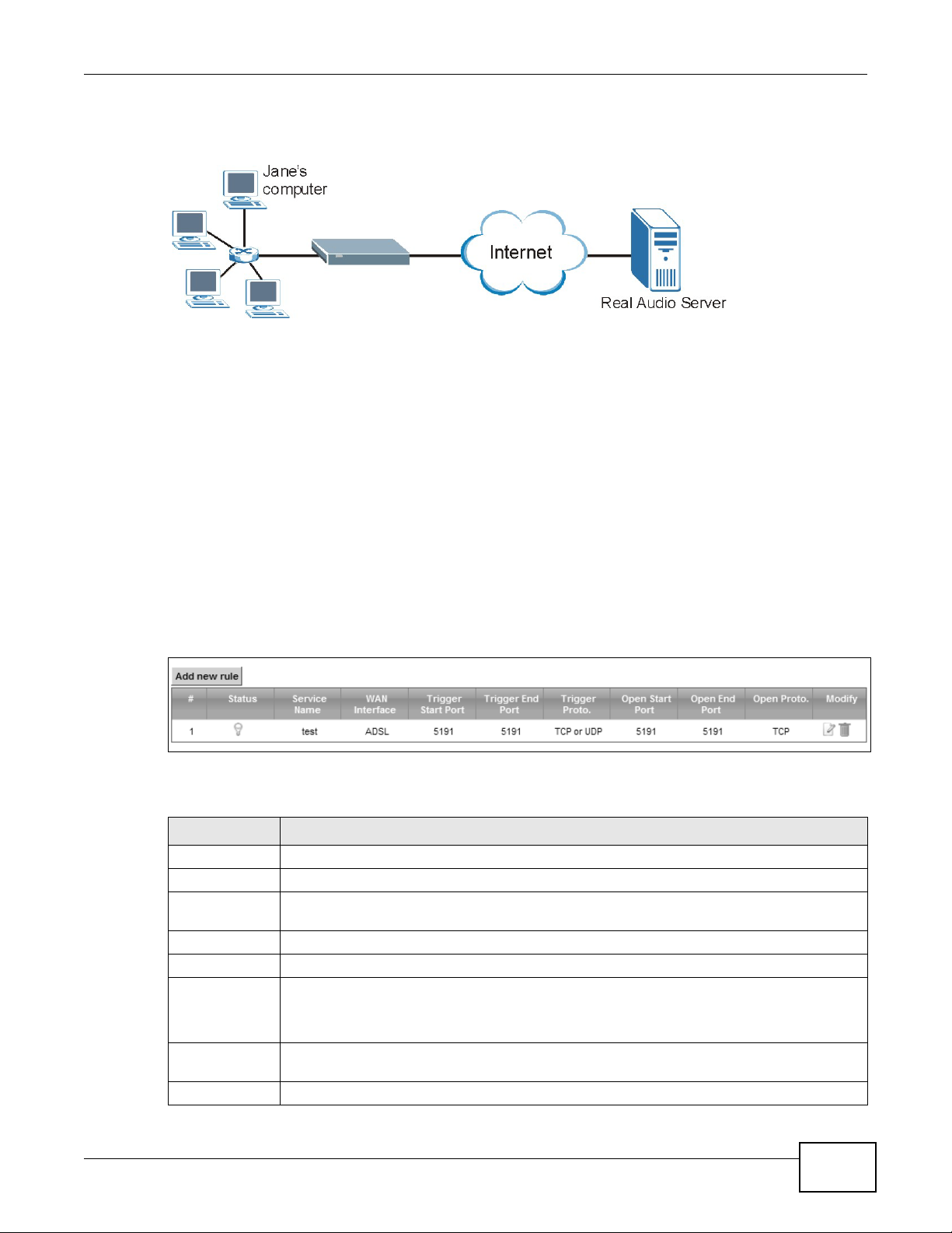
Click Network Setting > NAT > Port Triggering to open the following screen. Use this screen to
view your Device’s trigger port settings.
Figure 81 Network Setting > NAT > Port Triggering
The following table describes the labels in this screen.
Table 57 Network Setting > NAT > Port Triggering
LABEL DESCRIPTION
Add new rule Click this to create a new rule.
# This is the index number of the entry.
Status This field displays whether the port triggering rule is active or not. A yellow bulb signifies
that this rule is active. A gray bulb signifies that this rule is not active.
Service Name This field displays the name of the service used by this rule.
WAN Interface This field shows the WAN interface through which the service is forwarded.
Trigger Start
Port
The trigger port is a port (or a range of ports) that causes (or triggers) the Device to record
the IP address of the LAN computer that sent the traffic to a server on the WAN.
This is the first port number that identifies a service.
Trigger End
Port
This is the last port number that identifies a service.
Trigger Proto. This is the trigger transport layer protocol.
Chapter 11 Network Address Translation (NAT)
VMG4380-B10A / VMG4325-B10A User’s Guide
184
11.4.1 Add/Edit Port Triggering Rule
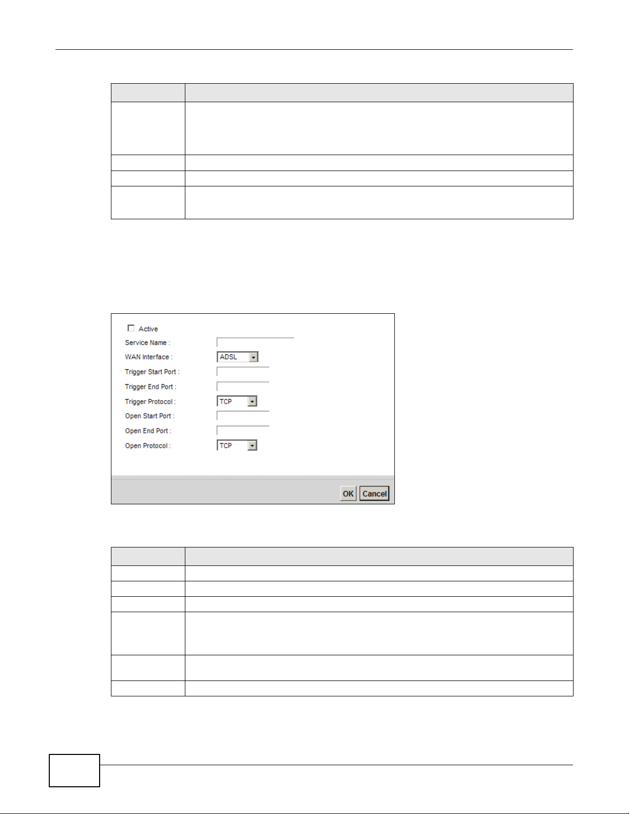
This screen lets you create new port triggering rules. Click Add new rule in the Port Triggering
screen or click a rule’s Edit icon to open the following screen.
Figure 82 Port Triggering: Add/Edit
The following table describes the labels in this screen.
Open Start Port The open port is a port (or a range of ports) that a server on the WAN uses when it sends
out a particular service. The Device forwards the traffic with this port (or range of ports) to
the client computer on the LAN that requested the service.
This is the first port number that identifies a service.
Open End Port This is the last port number that identifies a service.
Open Proto. This is the open transport layer protocol.
Modify Click the Edit icon to edit this rule.
Click the Delete icon to delete an existing rule.
Table 57 Network Setting > NAT > Port Triggering (continued)
LABEL DESCRIPTION
Table 58 Port Triggering: Configuration Add/Edit
LABEL DESCRIPTION
Active Select the check box to enable this rule.
Service Name Enter a name to identify this rule using keyboard characters (A-Z, a-z, 1-2 and so on).
WAN Interface Select a WAN interface for which you want to configure port triggering rules.
Trigger Start
Port
The trigger port is a port (or a range of ports) that causes (or triggers) the Device to record
the IP address of the LAN computer that sent the traffic to a server on the WAN.
Type a port number or the starting port number in a range of port numbers.
Trigger End
Port
Type a port number or the ending port number in a range of port numbers.
Trigger Protocol Select the transport layer protocol from TCP, UDP, or TCP/UDP.
Chapter 11 Network Address Translation (NAT)
VMG4380-B10A / VMG4325-B10A User’s Guide
185
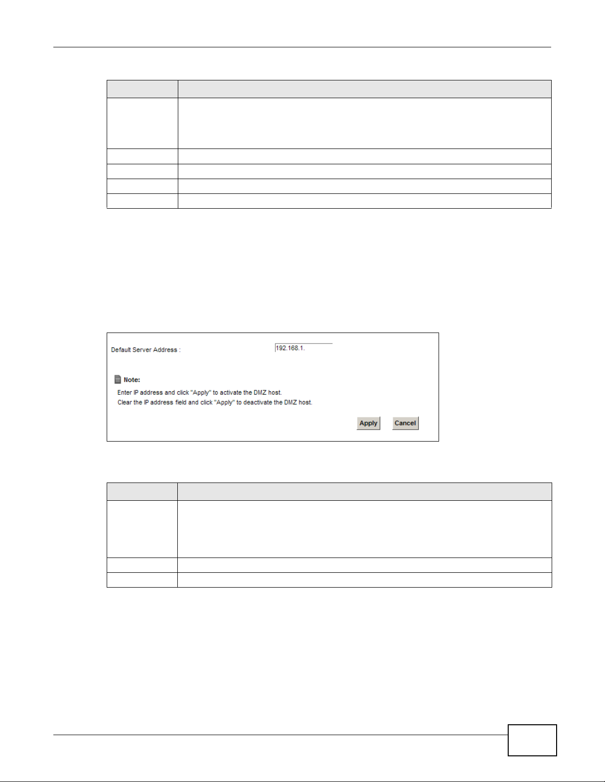
11.5 The DMZ Screen
In addition to the servers for specified services, NAT supports a default server IP address. A default
server receives packets from ports that are not specified in the NAT Port Forwarding Setup
screen.
Figure 83 Network Setting > NAT > DMZ
The following table describes the fields in this screen.
Open Start Port The open port is a port (or a range of ports) that a server on the WAN uses when it sends
out a particular service. The Device forwards the traffic with this port (or range of ports) to
the client computer on the LAN that requested the service.
Type a port number or the starting port number in a range of port numbers.
Open End Port Type a port number or the ending port number in a range of port numbers.
Open Protocol Select the transport layer protocol from TCP, UDP, or TCP/UDP.
OK Click OK to save your changes.
Cancel Click Cancel to exit this screen without saving.
Table 58 Port Triggering: Configuration Add/Edit (continued)
LABEL DESCRIPTION
Table 59 Network Setting > NAT > DMZ
LABEL DESCRIPTION
Default Server
Address
Enter the IP address of the default server which receives packets from ports that are not
specified in the NAT Port Forwarding screen.
Note: If you do not assign a Default Server Address, the Device discards all packets
received for ports that are not specified in the NAT Port Forwarding screen.
Apply Click Apply to save your changes.
Cancel Click Cancel to restore your previously saved settings.
Chapter 11 Network Address Translation (NAT)
VMG4380-B10A / VMG4325-B10A User’s Guide
186
11.6 The ALG Screen
Some NAT routers may include a SIP Application Layer Gateway (ALG). A SIP ALG allows SIP calls
to pass through NAT by examining and translating IP addresses embedded in the data stream.
When the Device registers with the SIP register server, the SIP ALG translates the Device’s private
IP address inside the SIP data stream to a public IP address. You do not need to use STUN or an
outbound proxy if your Device is behind a SIP ALG.
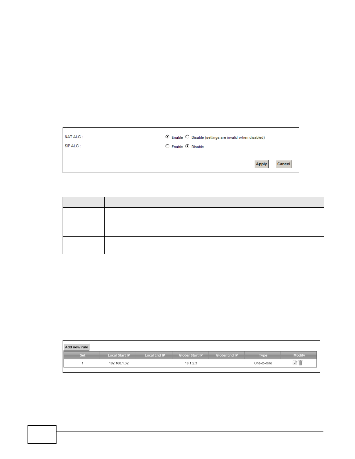
Use this screen to enable and disable the NAT and SIP (VoIP) ALG in the Device. To access this
screen, click Network Setting > NAT > ALG.
Figure 84 Network Setting > NAT > ALG
The following table describes the fields in this screen.
11.7 The Address Mapping Screen
Ordering your rules is important because the Device applies the rules in the order that you specify.
When a rule matches the current packet, the Device takes the corresponding action and the
remaining rules are ignored.
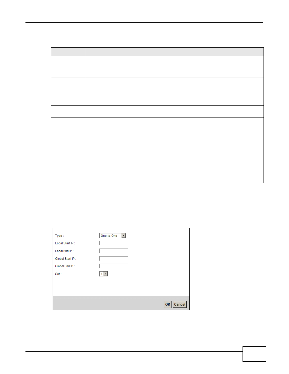
Click Network Setting > NAT > Address Mapping to display the following screen.
Figure 85 Network Setting > NAT > Address Mapping
Table 60 Network Setting > NAT > ALG
LABEL DESCRIPTION
NAT ALG Enable this to make sure applications such as FTP and file transfer in IM applications work
correctly with port-forwarding and address-mapping rules.
SIP ALG
Enable this to make sure SIP (VoIP) works correctly with port-forwarding and addressmapping rules.
Apply Click Apply to save your changes.
Cancel Click Cancel to restore your previously saved settings.
Chapter 11 Network Address Translation (NAT)
VMG4380-B10A / VMG4325-B10A User’s Guide
187
The following table describes the fields in this screen.
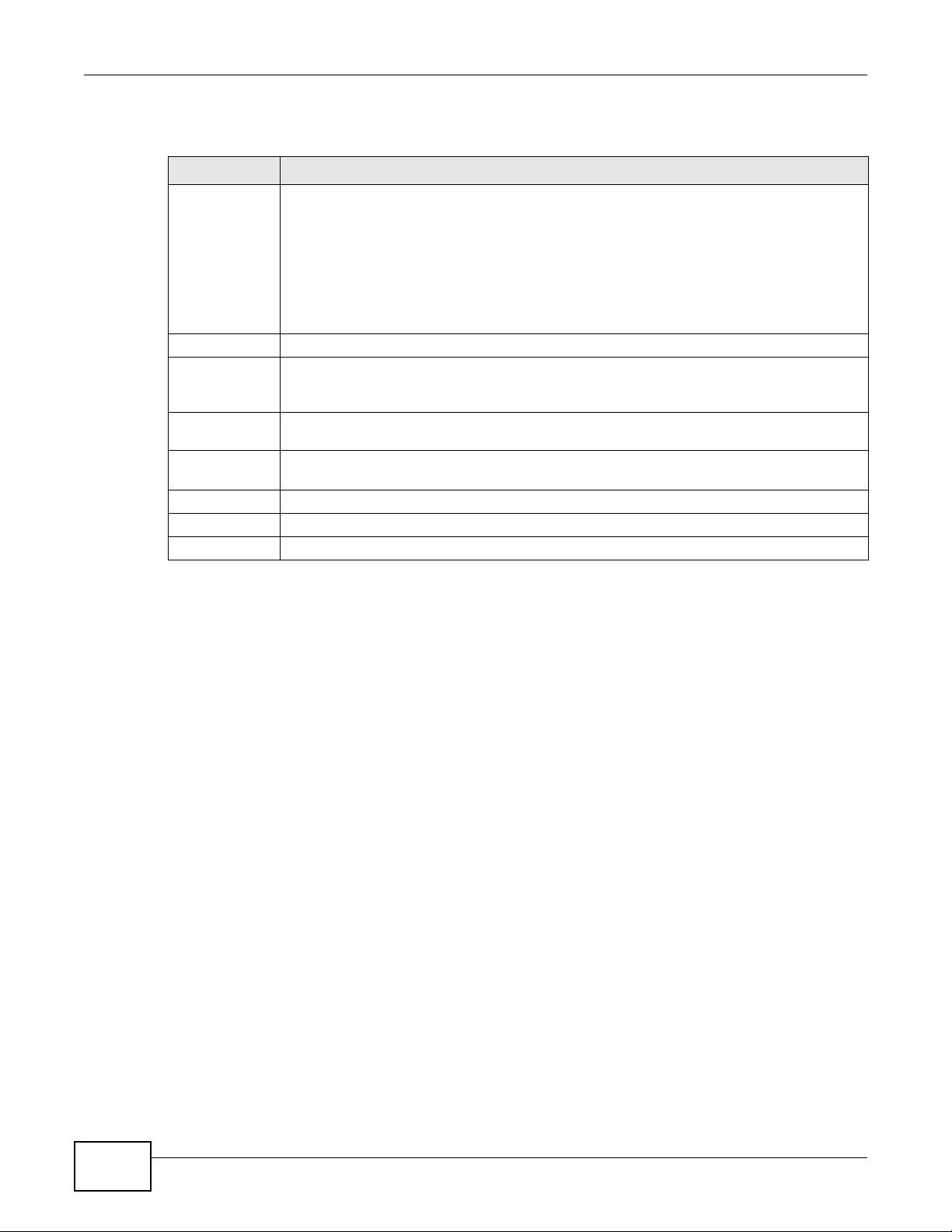
11.7.1 Add/Edit Address Mapping Rule
To add or edit an address mapping rule, click Add new rule or the rule’s edit icon in the Address
Mapping screen to display the screen shown next.
Figure 86 Address Mapping: Add/Edit
Table 61 Network Setting > NAT > Address Mapping
LABEL DESCRIPTION
Add new rule Click this to create a new rule.
Set This is the index number of the address mapping set.
Local Start IP This is the starting Inside Local IP Address (ILA).
Local End IP This is the ending Inside Local IP Address (ILA). If the rule is for all local IP addresses, then
this field displays 0.0.0.0 as the Local Start IP address and 255.255.255.255 as the Local
End IP address. This field is blank for One-to-One mapping types.
Global Start IP This is the starting Inside Global IP Address (IGA). Enter 0.0.0.0 here if you have a dynamic
IP address from your ISP. You can only do this for the Many-to-One mapping type.
Global End IP This is the ending Inside Global IP Address (IGA). This field is blank for One-to-One and
Many-to-One mapping types.
Type This is the address mapping type.
One-to-One: This mode maps one local IP address to one global IP address. Note that port
numbers do not change for the One-to-one NAT mapping type.
Many-to-One: This mode maps multiple local IP addresses to one global IP address. This is
equivalent to SUA (i.e., PAT, port address translation), the Device's Single User Account
feature that previous routers supported only.
Many-to-Many: This mode maps multiple local IP addresses to shared global IP addresses.
Modify Click the Edit icon to go to the screen where you can edit the address mapping rule.
Click the Delete icon to delete an existing address mapping rule. Note that subsequent
address mapping rules move up by one when you take this action.
Chapter 11 Network Address Translation (NAT)
VMG4380-B10A / VMG4325-B10A User’s Guide
188
The following table describes the fields in this screen.
11.8 Technical Reference
This part contains more information regarding NAT.
11.8.1 NAT Definitions
Inside/outside denotes where a host is located relative to the Device, for example, the computers
of your subscribers are the inside hosts, while the web servers on the Internet are the outside
hosts.
Global/local denotes the IP address of a host in a packet as the packet traverses a router, for
example, the local address refers to the IP address of a host when the packet is in the local
network, while the global address refers to the IP address of the host when the same packet is
traveling in the WAN side.
Table 62 Address Mapping: Add/Edit
LABEL DESCRIPTION
Type Choose the IP/port mapping type from one of the following.
One-to-One: This mode maps one local IP address to one global IP address. Note that port
numbers do not change for the One-to-one NAT mapping type.
Many-to-One: This mode maps multiple local IP addresses to one global IP address. This is
equivalent to SUA (i.e., PAT, port address translation), the Device's Single User Account
feature that previous routers supported only.
Many-to-Many: This mode maps multiple local IP addresses to shared global IP addresses.
Local Start IP
Enter the starting Inside Local IP Address (ILA).
Local End IP Enter the ending Inside Local IP Address (ILA). If the rule is for all local IP addresses, then
this field displays 0.0.0.0 as the Local Start IP address and 255.255.255.255 as the Local
End IP address. This field is blank for One-to-One mapping types.
Global Start IP Enter the starting Inside Global IP Address (IGA). Enter 0.0.0.0 here if you have a dynamic
IP address from your ISP. You can only do this for the Many-to-One mapping type.
Global End IP Enter the ending Inside Global IP Address (IGA). This field is blank for One-to-One and
Many-to-One mapping types.
Set Select the number of the mapping set for which you want to configure.
OK Click OK to save your changes.
Cancel Click Cancel to exit this screen without saving.
Chapter 11 Network Address Translation (NAT)
VMG4380-B10A / VMG4325-B10A User’s Guide
189
Note that inside/outside refers to the location of a host, while global/local refers to the IP address
of a host used in a packet. Thus, an inside local address (ILA) is the IP address of an inside host in
a packet when the packet is still in the local network, while an inside global address (IGA) is the IP
address of the same inside host when the packet is on the WAN side. The following table
summarizes this information.
NAT never changes the IP address (either local or global) of an outside host.
11.8.2 What NAT Does
In the simplest form, NAT changes the source IP address in a packet received from a subscriber
(the inside local address) to another (the inside global address) before forwarding the packet to the
WAN side. When the response comes back, NAT translates the destination address (the inside
global address) back to the inside local address before forwarding it to the original inside host. Note
that the IP address (either local or global) of an outside host is never changed.
The global IP addresses for the inside hosts can be either static or dynamically assigned by the ISP.
In addition, you can designate servers, for example, a web server and a telnet server, on your local
network and make them accessible to the outside world. If you do not define any servers (for Manyto-One and Many-to-Many Overload mapping), NAT offers the additional benefit of firewall
protection. With no servers defined, your Device filters out all incoming inquiries, thus preventing
intruders from probing your network. For more information on IP address translation, refer to RFC
1631, The IP Network Address Translator (NAT).
Table 63 NAT Definitions
ITEM DESCRIPTION
Inside This refers to the host on the LAN.
Outside This refers to the host on the WAN.
Local This refers to the packet address (source or destination) as the packet travels on the
LAN.
Global This refers to the packet address (source or destination) as the packet travels on the
WAN.
Chapter 11 Network Address Translation (NAT)
VMG4380-B10A / VMG4325-B10A User’s Guide
190
11.8.3 How NAT Works
Each packet has two addresses – a source address and a destination address. For outgoing packets,
the ILA (Inside Local Address) is the source address on the LAN, and the IGA (Inside Global
Address) is the source address on the WAN. For incoming packets, the ILA is the destination
address on the LAN, and the IGA is the destination address on the WAN. NAT maps private (local)
IP addresses to globally unique ones required for communication with hosts on other networks. It
replaces the original IP source address (and TCP or UDP source port numbers for Many-to-One and
Many-to-Many Overload NAT mapping) in each packet and then forwards it to the Internet. The
Device keeps track of the original addresses and port numbers so incoming reply packets can have
their original values restored. The following figure illustrates this.
Figure 87 How NAT Works
192.168.1.13
192.168.1.10
192.168.1.11
192.168.1.12
SA
192.168.1.10
SA
IGA1
Inside Local
IP Address
192.168.1.10
192.168.1.11
192.168.1.12
192.168.1.13
Inside Global
IP Address
IGA 1
IGA 2
IGA 3
IGA 4
NAT Table
WAN
LAN
Inside Local
Address (ILA)
Inside Global
Address (IGA)
Chapter 11 Network Address Translation (NAT)
VMG4380-B10A / VMG4325-B10A User’s Guide
191
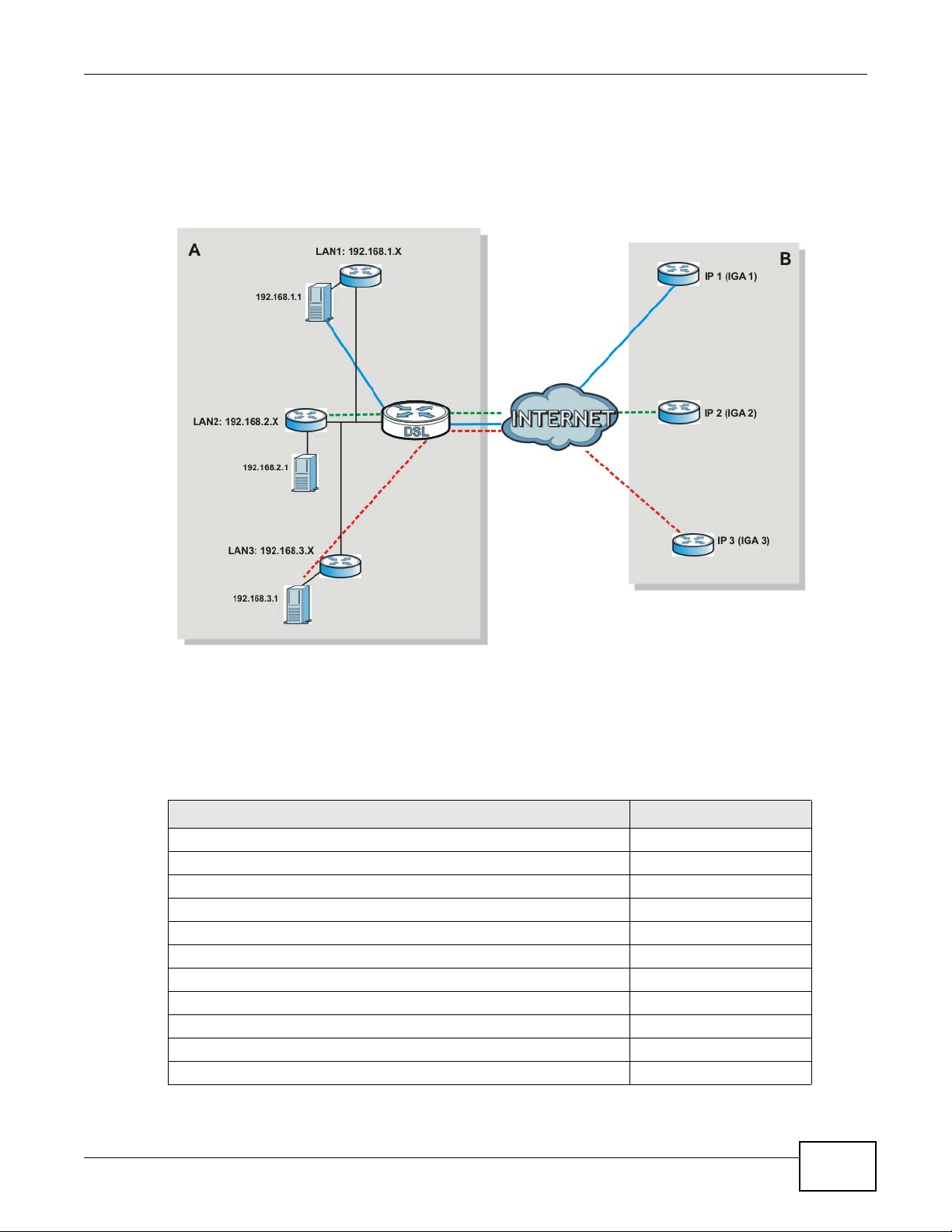
11.8.4 NAT Application
The following figure illustrates a possible NAT application, where three inside LANs (logical LANs
using IP alias) behind the Device can communicate with three distinct WAN networks.
Figure 88 NAT Application With IP Alias
Port Forwarding: Services and Port Numbers
The most often used port numbers are shown in the following table. Please refer to RFC 1700 for
further information about port numbers. Please also refer to the Supporting CD for more examples
and details on port forwarding and NAT.
Table 64 Services and Port Numbers
SERVICES PORT NUMBER
ECHO 7
FTP (File Transfer Protocol) 21
SMTP (Simple Mail Transfer Protocol) 25
DNS (Domain Name System) 53
Finger 79
HTTP (Hyper Text Transfer protocol or WWW, Web) 80
POP3 (Post Office Protocol) 110
NNTP (Network News Transport Protocol) 119
SNMP (Simple Network Management Protocol) 161
SNMP trap 162
PPTP (Point-to-Point Tunneling Protocol) 1723
Chapter 11 Network Address Translation (NAT)
VMG4380-B10A / VMG4325-B10A User’s Guide
192
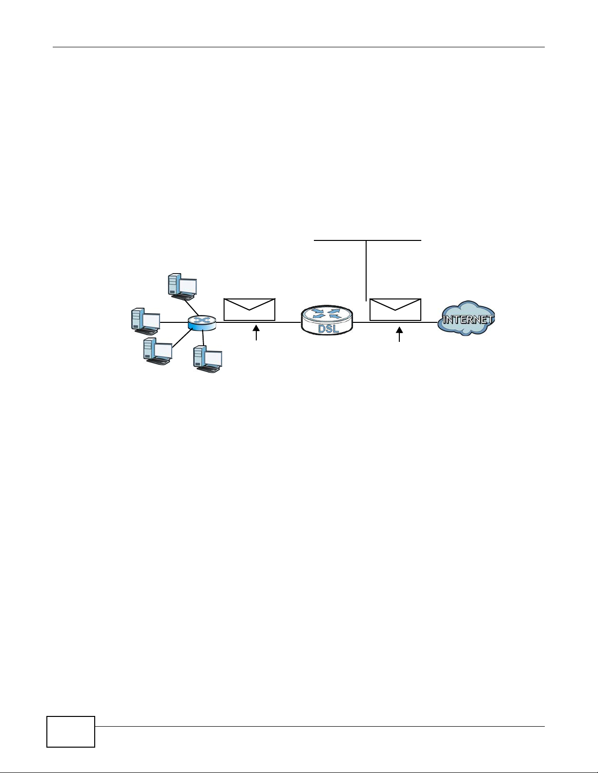
Port Forwarding Example
Let's say you want to assign ports 21-25 to one FTP, Telnet and SMTP server (A in the example),
port 80 to another (B in the example) and assign a default server IP address of 192.168.1.35 to a
third (C in the example). You assign the LAN IP addresses and the ISP assigns the WAN IP address.
The NAT network appears as a single host on the Internet.
Figure 89 Multiple Servers Behind NAT Example
D=192.168.1.36
192.168.1.1
IP address assigned by ISP
A=192.168.1.33
B=192.168.1.34
C=192.168.1.35

VMG4380-B10A / VMG4325-B10A User’s Guide 193
CHAPTER 12
Dynamic DNS Setup
12.1 Overview
DNS
DNS (Domain Name System) is for mapping a domain name to its corresponding IP address and
vice versa. The DNS server is extremely important because without it, you must know the IP
address of a machine before you can access it.
In addition to the system DNS server(s), each WAN interface (service) is set to have its own static
or dynamic DNS server list. You can configure a DNS static route to forward DNS queries for certain
domain names through a specific WAN interface to its DNS server(s). The Device uses a system
DNS server (in the order you specify in the Broadband screen) to resolve domain names that do
not match any DNS routing entry. After the Device receives a DNS reply from a DNS server, it
creates a new entry for the resolved IP address in the routing table.
Dynamic DNS
Dynamic DNS allows you to update your current dynamic IP address with one or many dynamic
DNS services so that anyone can contact you (in NetMeeting, CU-SeeMe, etc.). You can also access
your FTP server or Web site on your own computer using a domain name (for instance
myhost.dhs.org, where myhost is a name of your choice) that will never change instead of using an
IP address that changes each time you reconnect. Your friends or relatives will always be able to
call you even if they don't know your IP address.
First of all, you need to have registered a dynamic DNS account with www.dyndns.org. This is for
people with a dynamic IP from their ISP or DHCP server that would still like to have a domain name.
The Dynamic DNS service provider will give you a password or key.
12.1.1 What You Can Do in this Chapter
• Use the DNS Entry screen to view, configure, or remove DNS routes (Section 12.2 on page
194).
• Use the Dynamic DNS screen to enable DDNS and configure the DDNS settings on the Device
(Section 12.3 on page 195).
Chapter 12 Dynamic DNS Setup
VMG4380-B10A / VMG4325-B10A User’s Guide
194
12.1.2 What You Need To Know
DYNDNS Wildcard
Enabling the wildcard feature for your host causes *.yourhost.dyndns.org to be aliased to the same
IP address as yourhost.dyndns.org. This feature is useful if you want to be able to use, for example,
www.yourhost.dyndns.org and still reach your hostname.
If you have a private WAN IP address, then you cannot use Dynamic DNS.
12.2 The DNS Entry Screen
Use this screen to view and configure DNS routes on the Device. Click Network Setting > DNS to
open the DNS Entry screen.
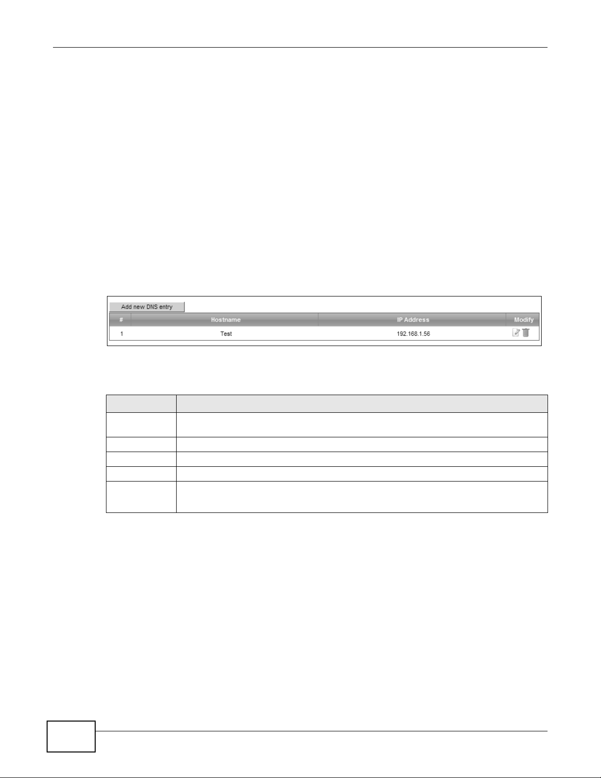
Figure 90 Network Setting > DNS > DNS Entry
The following table describes the fields in this screen.
Table 65 Network Setting > DNS > DNS Entry
LABEL DESCRIPTION
Add new DNS
entry
Click this to create a new DNS entry.
# This is the index number of the entry.
Hostname This indicates the host name or domain name.
IP Address This indicates the IP address assigned to this computer.
Modify Click the Edit icon to edit the rule.
Click the Delete icon to delete an existing rule.
Chapter 12 Dynamic DNS Setup
VMG4380-B10A / VMG4325-B10A User’s Guide
195
12.2.1 Add/Edit DNS Entry
You can manually add or edit the Device’s DNS name and IP address entry. Click Add new DNS
entry in the DNS Entry screen or the Edit icon next to the entry you want to edit. The screen
shown next appears.
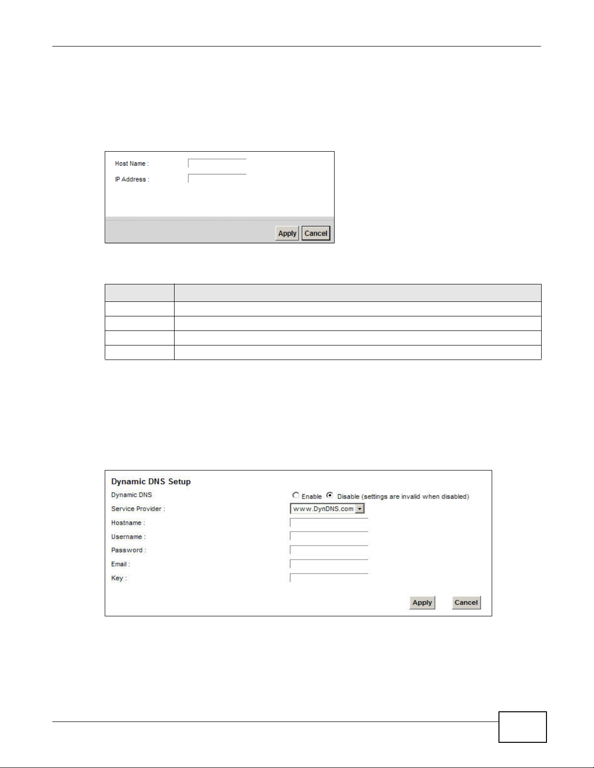
Figure 91 DNS Entry: Add/Edit
The following table describes the labels in this screen.
12.3 The Dynamic DNS Screen
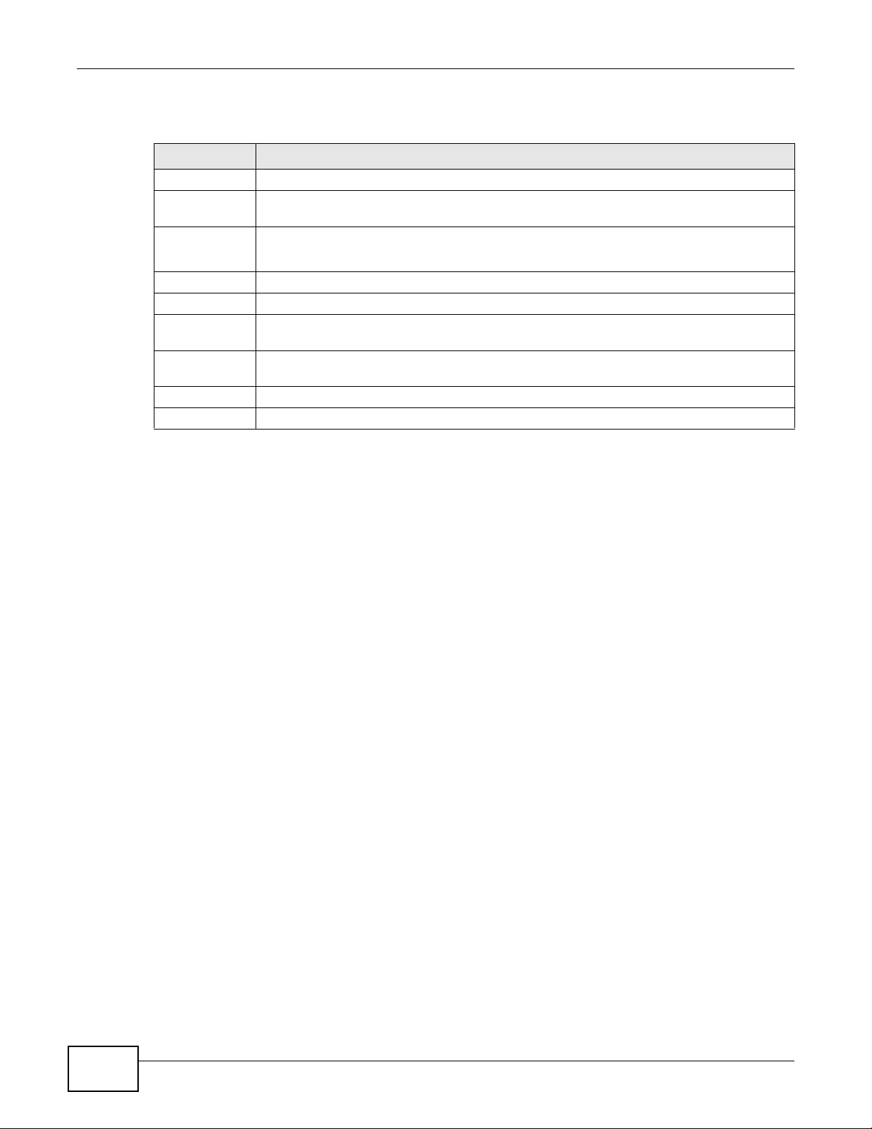
Use this screen to change your Device’s DDNS. Click Network Setting > DNS > Dynamic DNS.
The screen appears as shown.
Figure 92 Network Setting > DNS > Dynamic DNS
Table 66 DNS Entry: Add/Edit
LABEL DESCRIPTION
Host Name Enter the host name of the DNS entry.
IP Address Enter the IP address of the DNS entry.
Apply Click Apply to save your changes.
Cancel Click Cancel to exit this screen without saving.
Chapter 12 Dynamic DNS Setup
VMG4380-B10A / VMG4325-B10A User’s Guide
196
The following table describes the fields in this screen.
Table 67 Network Setting > DNS > > Dynamic DNS
LABEL DESCRIPTION
Dynamic DNS Select Enable to use dynamic DNS.
Service
Provider
Select your Dynamic DNS service provider from the drop-down list box.
Hostname Type the domain name assigned to your Device by your Dynamic DNS provider.
You can specify up to two host names in the field separated by a comma (",").
Username Type your user name.
Password Type the password assigned to you.
Email If you select TZO in the Service Provider field, enter the user name you used to register
for this service.
Key If you select TZO in the Service Provider field, enter the password you used to register for
this service.
Apply Click Apply to save your changes.
Cancel Click Cancel to exit this screen without saving.

VMG4380-B10A / VMG4325-B10A User’s Guide 197
CHAPTER 13
Interface Group
13.1 Overview
By default, all LAN and WAN interfaces on the Device are in the same group and can communicate
with each other. Create interface groups to have the Device assign the IP addresses in different
domains to different groups. Each group acts as an independent network on the Device. This lets
devices connected to an interface group’s LAN interfaces communicate through the interface
group’s WAN or LAN interfaces but not other WAN or LAN interfaces.
13.1.1 What You Can Do in this Chapter
The Interface Group screens let you create multiple networks on the Device (Section 13.2 on
page 197).
13.2 The Interface Group Screen
You can manually add a LAN interface to a new group. Alternatively, you can have the Device
automatically add the incoming traffic and the LAN interface on which traffic is received to an
interface group when its DHCP Vendor ID option information matches one listed for the interface
group.
Use the LAN screen to configure the private IP addresses the DHCP server on the Device assigns to
the clients in the default and/or user-defined groups. If you set the Device to assign IP addresses
based on the client’s DHCP Vendor ID option information, you must enable DHCP server and
configure LAN TCP/IP settings for both the default and user-defined groups. See Chapter 8 on page
131 for more information.
Chapter 13 Interface Group
VMG4380-B10A / VMG4325-B10A User’s Guide
198
In the following example, the client that sends packets with the DHCP Vendor ID option set to MSFT
5.0 (meaning it is a Windows 2000 DHCP client) is assigned the IP address 192.168.2.2 and uses
the WAN VDSL_PoE/ppp0.1 interface.
Figure 93 Interface Grouping Application
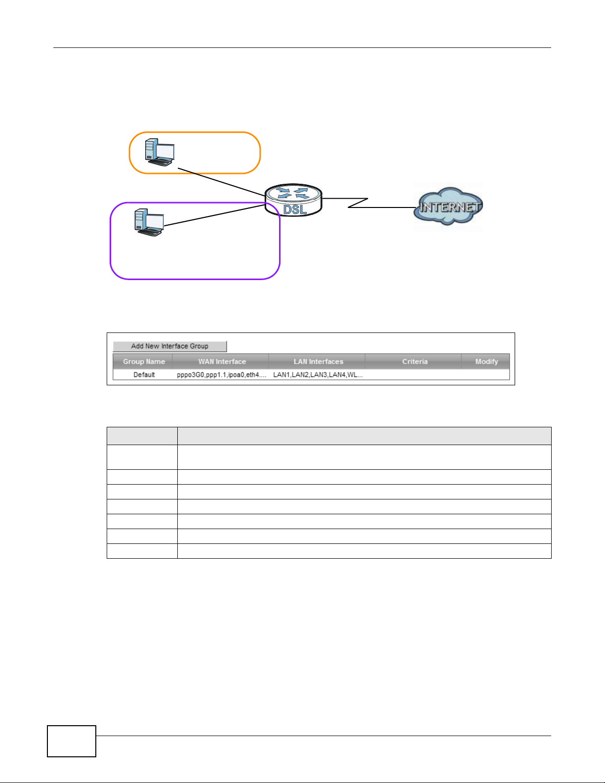
Click Network Setting > Interface Group to open the following screen.
Figure 94 Network Setting > Interface Group
The following table describes the fields in this screen.
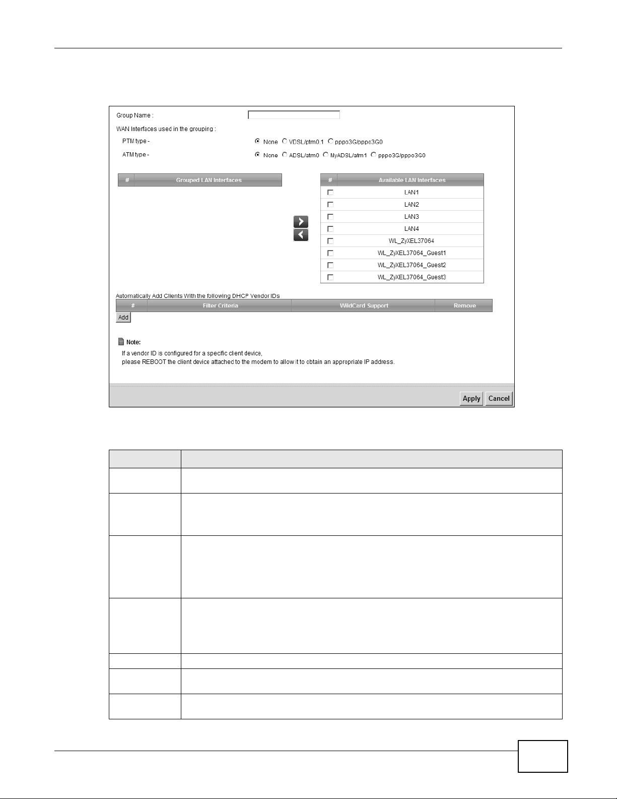
13.2.1 Interface Group Configuration
Click the Add New Interface Group button in the Interface Group screen to open the following
screen. Use this screen to create a new interface group.
Table 68 Network Setting > Interface Group
LABEL DESCRIPTION
Add New
Interface Group
Click this button to create a new interface group.
Group Name This shows the descriptive name of the group.
WAN Interface This shows the WAN interfaces in the group.
LAN Interfaces This shows the LAN interfaces in the group.
Criteria This shows the filtering criteria for the group.
Modify Click the Delete icon to remove the group.
Add Click this button to create a new group.
Default: ETH 2~4
Internet
192.168.1.x/24
192.168.2.x/24
VDSL_PoE/ppp0.1
eth10.0
DHCP Vendor ID option: MSFT 5.0
Chapter 13 Interface Group
VMG4380-B10A / VMG4325-B10A User’s Guide
199
Note: An interface can belong to only one group at a time.
Figure 95 Interface Group Configuration
The following table describes the fields in this screen.
Table 69 Interface Group Configuration
LABEL DESCRIPTION
Group Name Enter a name to identify this group. You can enter up to 30 characters. You can use letters,
numbers, hyphens (-) and underscores (_). Spaces are not allowed.
WAN Interface
used in the
grouping
Select the WAN interface this group uses. The group can have up to one PTM interface and
up to one ATM interface.
Select None to not add a WAN interface to this group.
Grouped LAN
Interfaces
Available LAN
Interfaces
Select one or more LAN interfaces (Ethernet LAN, HPNA or wireless LAN) in the Available
LAN Interfaces list and use the left arrow to move them to the Grouped LAN Interfaces
list to add the interfaces to this group.
To remove a LAN or wireless LAN interface from the Grouped LAN Interfaces, use the
right-facing arrow.
Automatically
Add Clients
With the
following DHCP
Vendor IDs
Click Add to identify LAN hosts to add to the interface group by criteria such as the type of
the hardware or firmware. See Section 13.2.2 on page 200 for more information.
# This shows the index number of the rule.
Filter Criteria This shows the filtering criteria. The LAN interface on which the matched traffic is received
will belong to this group automatically.
WildCard
Support
This shows if wildcard on DHCP option 60 is enabled.
Chapter 13 Interface Group
VMG4380-B10A / VMG4325-B10A User’s Guide
200
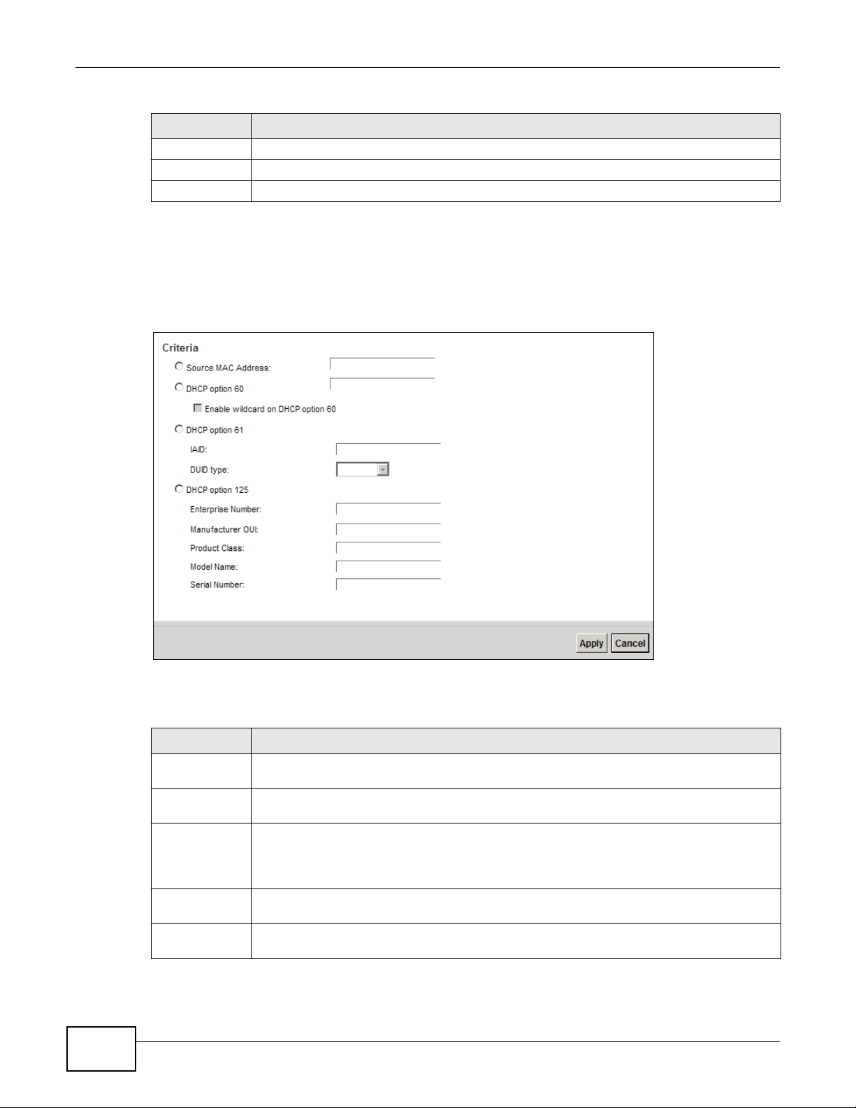
13.2.2 Interface Grouping Criteria
Click the Add button in the Interface Grouping Configuration screen to open the following
screen.
Figure 96 Interface Grouping Criteria
The following table describes the fields in this screen.
Remove Click the Remove icon to delete this rule from the Device.
Apply Click Apply to save your changes back to the Device.
Cancel Click Cancel to exit this screen without saving.
Table 69 Interface Group Configuration (continued)
LABEL DESCRIPTION
Table 70 Interface Grouping Criteria
LABEL DESCRIPTION
Source MAC
Address
Enter the source MAC address of the packet.
DHCP Option
60
Select this option and enter the Vendor Class Identifier (Option 60) of the matched traffic,
such as the type of the hardware or firmware.
Enable
wildcard on
DHCP
option 60
option
Select this option to be able to use wildcards in the Vendor Class Identifier configured for
DHCP option 60.
DHCP Option
61
Select this and enter the device identity of the matched traffic.
IAID Enter the Identity Association Identifier (IAID) of the device, for example, the WAN
connection index number.
Chapter 13 Interface Group
VMG4380-B10A / VMG4325-B10A User’s Guide
201
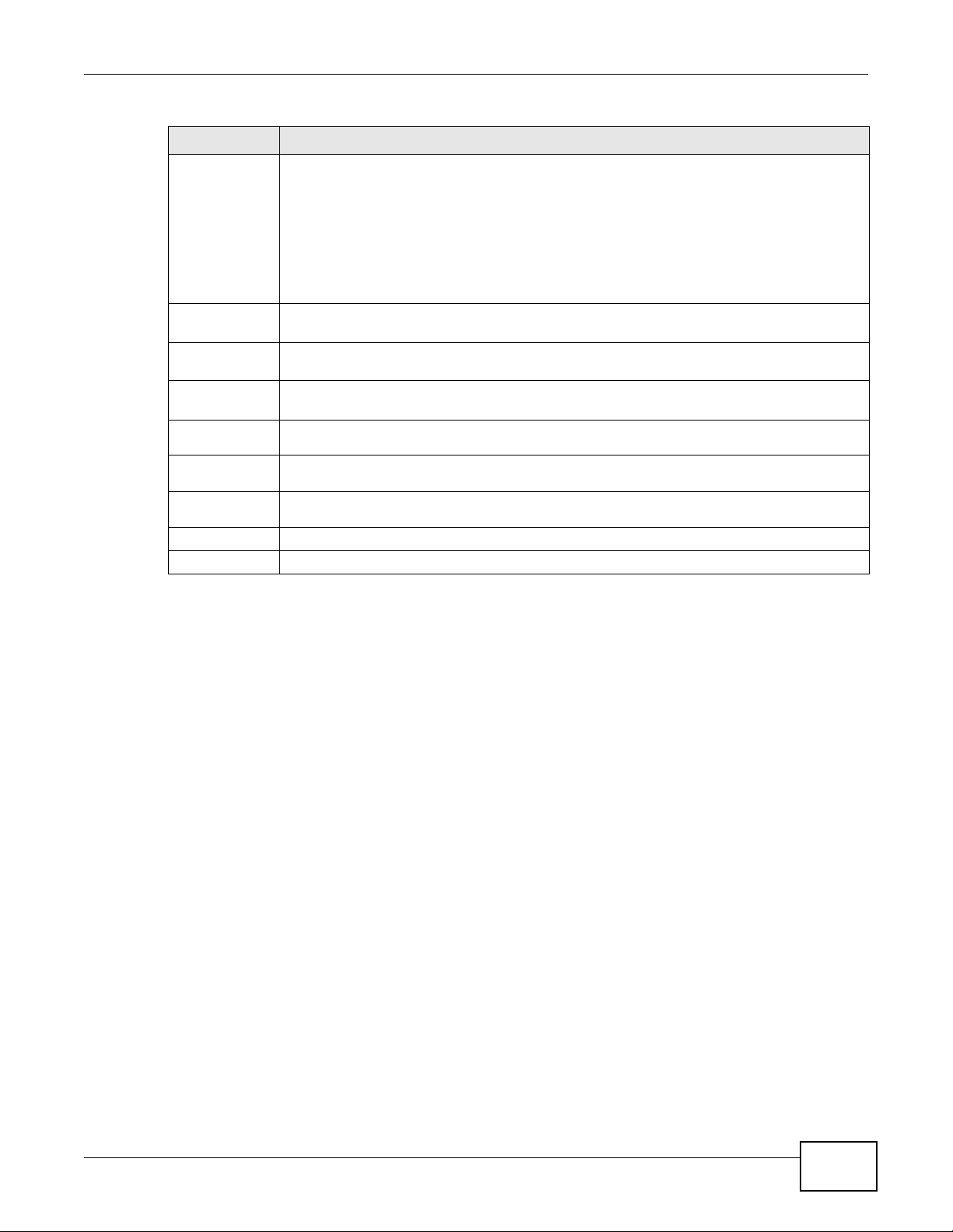
DUID type Select DUID-LLT (DUID Based on Link-layer Address Plus Time) to enter the hardware
type, a time value and the MAC address of the device.
Select DUID-EN (DUID Assigned by Vendor Based upon Enterprise Number) to enter the
vendor’s registered enterprise number.
Select DUID-LL (DUID Based on Link-layer Address) to enter the device’s hardware type
and hardware address (MAC address) in the following fields.
Select Other to enter any string that identifies the device in the DUID field.
DHCP Option
125
Select this and enter vendor specific information of the matched traffic.
Enterprise
Number
Enter the vendor’s 32-bit enterprise number registered with the IANA (Internet Assigned
Numbers Authority).
Manufactur
er OUI
Specify the vendor’s OUI (Organization Unique Identifier). It is usually the first three bytes
of the MAC address.
Product
Class
Enter the product class of the device.
Model
Name
Enter the model name of the device.
Serial
Number
Enter the serial number of the device.
Apply Click Apply to save your changes back to the Device.
Cancel Click Cancel to exit this screen without saving.
Table 70 Interface Grouping Criteria (continued)
LABEL DESCRIPTION

Chapter 13 Interface Group
VMG4380-B10A / VMG4325-B10A User’s Guide
202

VMG4380-B10A / VMG4325-B10A User’s Guide 203
CHAPTER 14
USB Service
14.1 Overview
The Device has a USB port used to share files via a USB memory stick or a USB hard drive. In the
USB Service screens, you can enable file-sharing server, media server, and printer server.
14.1.1 What You Can Do in this Chapter
• Use the File Sharing screen to enable file-sharing server (Section 14.2 on page 204).
• Use the Media Server screen to enable or disable the sharing of media files (Section 14.3 on
page 206).
• Use the Printer Server screen to enable the print server (Section 14.4 on page 207).
14.1.2 What You Need To Know
The following terms and concepts may help as you read this chapter.
14.1.2.1 About File Sharing
Workgroup name
This is the name given to a set of computers that are connected on a network and share resources
such as a printer or files. Windows automatically assigns the workgroup name when you set up a
network.
Shares
When settings are set to default, each USB device connected to the Device is given a folder, called
a “share”. If a USB hard drive connected to the Device has more than one partition, then each
partition will be allocated a share. You can also configure a “share” to be a sub-folder or file on the
USB device.
File Systems
A file system is a way of storing and organizing files on your hard drive and storage device. Often
different operating systems such as Windows or Linux have different file systems. The file sharing
feature on your Device supports File Allocation Table (FAT) and FAT32.
Common Internet File System
The Device uses Common Internet File System (CIFS) protocol for its file sharing functions. CIFS
compatible computers can access the USB file storage devices connected to the Device. CIFS

Chapter 14 USB Service
VMG4380-B10A / VMG4325-B10A User’s Guide
204
protocol is supported on Microsoft Windows, Linux Samba and other operating systems (refer to
your systems specifications for CIFS compatibility).
14.1.2.2 About Printer Server
Print Server
This is a computer or other device which manages one or more printers, and which sends print jobs
to each printer from the computer itself or other devices.
Operating System
An operating system (OS) is the interface which helps you manage a computer. Common examples
are Microsoft Windows, Mac OS or Linux.
TCP/IP
TCP/IP (Transmission Control Protocol/ Internet Protocol) is a set of communications protocols that
most of the Internet runs on.
Port
A port maps a network service such as http to a process running on your computer, such as a
process run by your web browser. When traffic from the Internet is received on your computer, the
port number is used to identify which process running on your computer it is intended for.
Supported OSs
Your operating system must support TCP/IP ports for printing and be compatible with the RAW (port
9100) protocol.
The following OSs support Device’s printer sharing feature.
• Microsoft Windows 95, Windows 98 SE (Second Edition), Windows Me, Windows NT 4.0, Windows
2000, Windows XP or Macintosh OS X.
14.2 The File Sharing Screen
You can share files on a USB memory stick or hard drive connected to your Device with users on
your network.
Chapter 14 USB Service
VMG4380-B10A / VMG4325-B10A User’s Guide
205
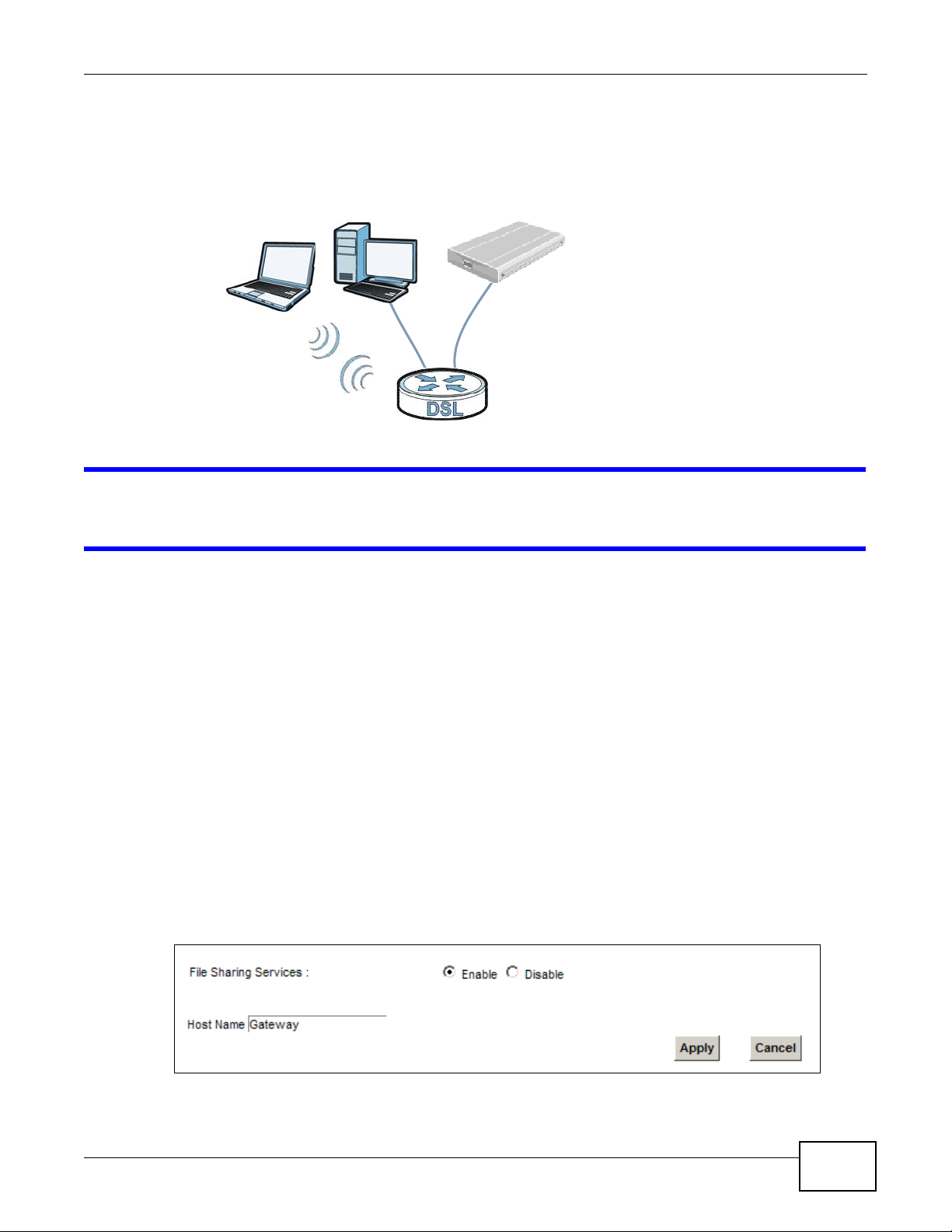
The following figure is an overview of the Device’s file server feature. Computers A and B can
access files on a USB device (C) which is connected to the Device.
Figure 97 File Sharing Overview
The Device will not be able to join the workgroup if your local area network has restrictions
set up that do not allow devices to join a workgroup. In this case, contact your network
administrator.
14.2.1 Before You Begin
Make sure the Device is connected to your network and turned on.
1 Connect the USB device to one of the Device’s USB port. Make sure the Device is connected to your
network.
2 The Device detects the USB device and makes its contents available for browsing. If you are
connecting a USB hard drive that comes with an external power supply, make sure it is connected
to an appropriate power source that is on.
Note: If your USB device cannot be detected by the Device, see the troubleshooting for
suggestions.
Use this screen to set up file sharing using the Device. To access this screen, click Network
Setting > USB Service > File Sharing.
Figure 98 Network Setting > USB Service > File Sharing
A
B
C
Chapter 14 USB Service
VMG4380-B10A / VMG4325-B10A User’s Guide
206
Each field is described in the following table.
14.3 The Media Server Screen
The media server feature lets anyone on your network play video, music, and photos from the USB
storage device connected to your Device (without having to copy them to another computer). The
Device can function as a DLNA-compliant media server. The Device streams files to DLNA-compliant
media clients (like Windows Media Player). The Digital Living Network Alliance (DLNA) is a group of
personal computer and electronics companies that works to make products compatible in a home
network.
The Device media server enables you to:
• Publish all shares for everyone to play media files in the USB storage device connected to the
Device.
• Use hardware-based media clients like the DMA-2500 to play the files.
Note: Anyone on your network can play the media files in the published shares. No user
name and password or other form of security is used. The media server is enabled
by default with the video, photo, and music shares published.
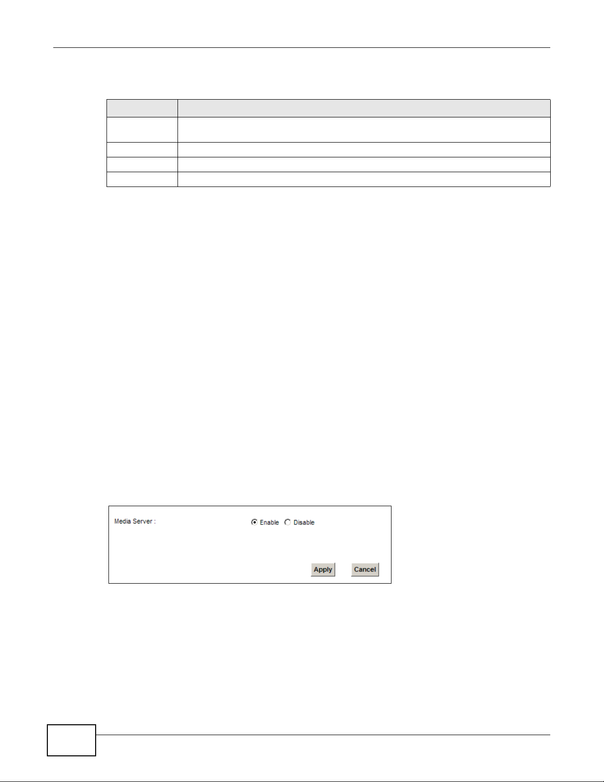
To change your Device’s media server settings, click Network Setting > USB Service > Media
Server. The screen appears as shown.
Figure 99 Network Setting > USB Service > Media Server
Table 71 Network Setting > Home Networking > File Sharing
LABEL DESCRIPTION
File Sharing
Services
Select Enable to activate file sharing through the Device.
Host Name Enter the host name on the share.
Apply Click Apply to save your changes.
Cancel Click Cancel to restore your previously saved settings.
Chapter 14 USB Service
VMG4380-B10A / VMG4325-B10A User’s Guide
207
The following table describes the labels in this menu.
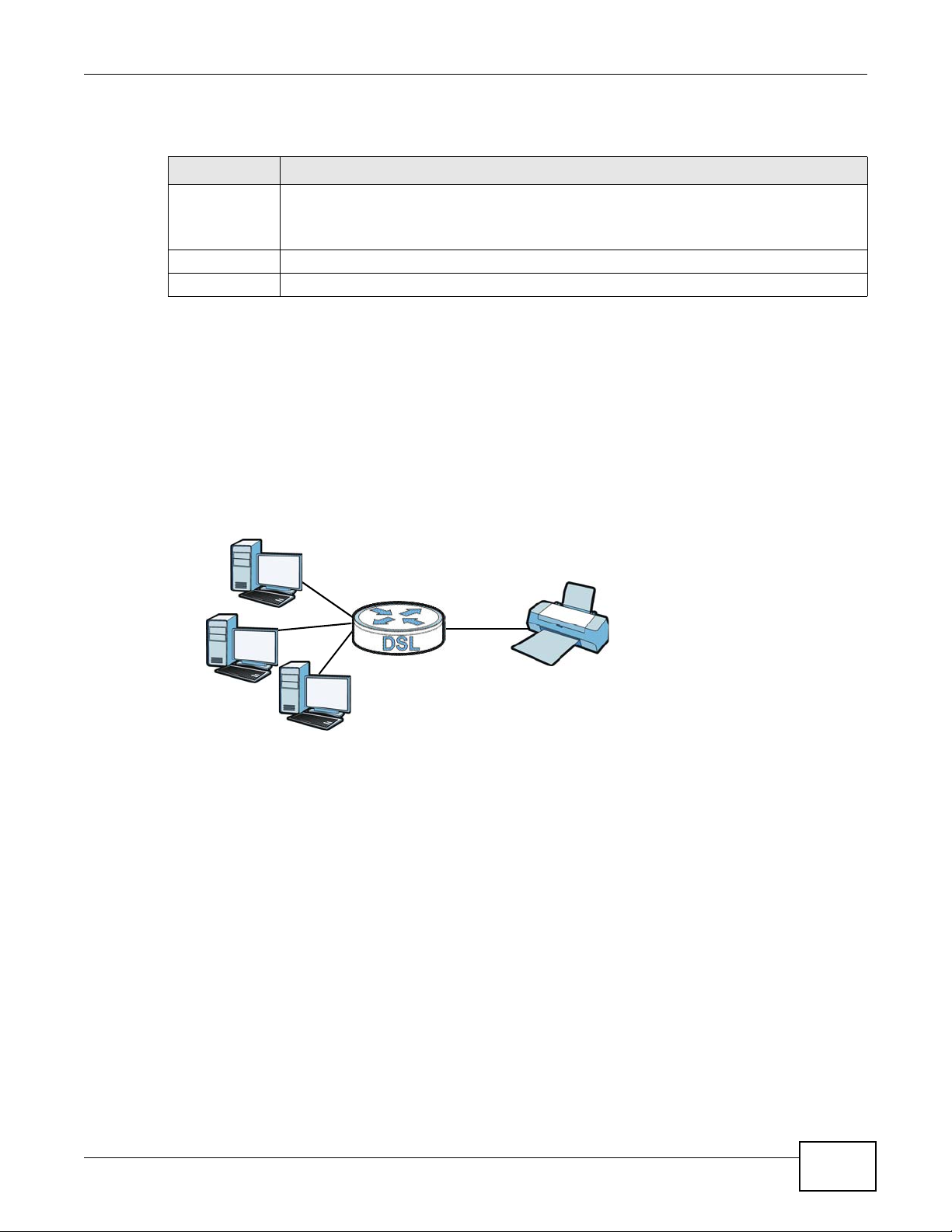
14.4 The Printer Server Screen
The Device allows you to share a USB printer on your LAN. You can do this by connecting a USB
printer to one of the USB ports on the Device and then adding the printer on the computers
connected to your network. See Section 4.11 on page 62 for instructions on adding a printer on
your computer.
Figure 100 Sharing a USB Printer
14.4.1 Before You Begin
To configure the print server you need the following:
• Your Device must be connected to your computer and any other devices on your network. The
USB printer must be connected to your Device.
• A USB printer with the driver already installed on your computer.
• See Section 4.11 on page 62 for instructions on adding a printer on your computer.
Note: Your printer’s installation instructions may ask that you connect the printer to your
computer. Connect your printer to the Device instead.
Use this screen to enable or disable sharing of a USB printer via your Device.
Table 72 Network Setting > USB Service > Media Server
LABEL DESCRIPTION
Media Server Select Enable to have the Device function as a DLNA-compliant media server.
Enable the media server to let (DLNA-compliant) media clients on your network play media
files located in the shares.
Apply Click Apply to save your changes.
Cancel Click Cancel to restore your previously saved settings.
Chapter 14 USB Service
VMG4380-B10A / VMG4325-B10A User’s Guide
208
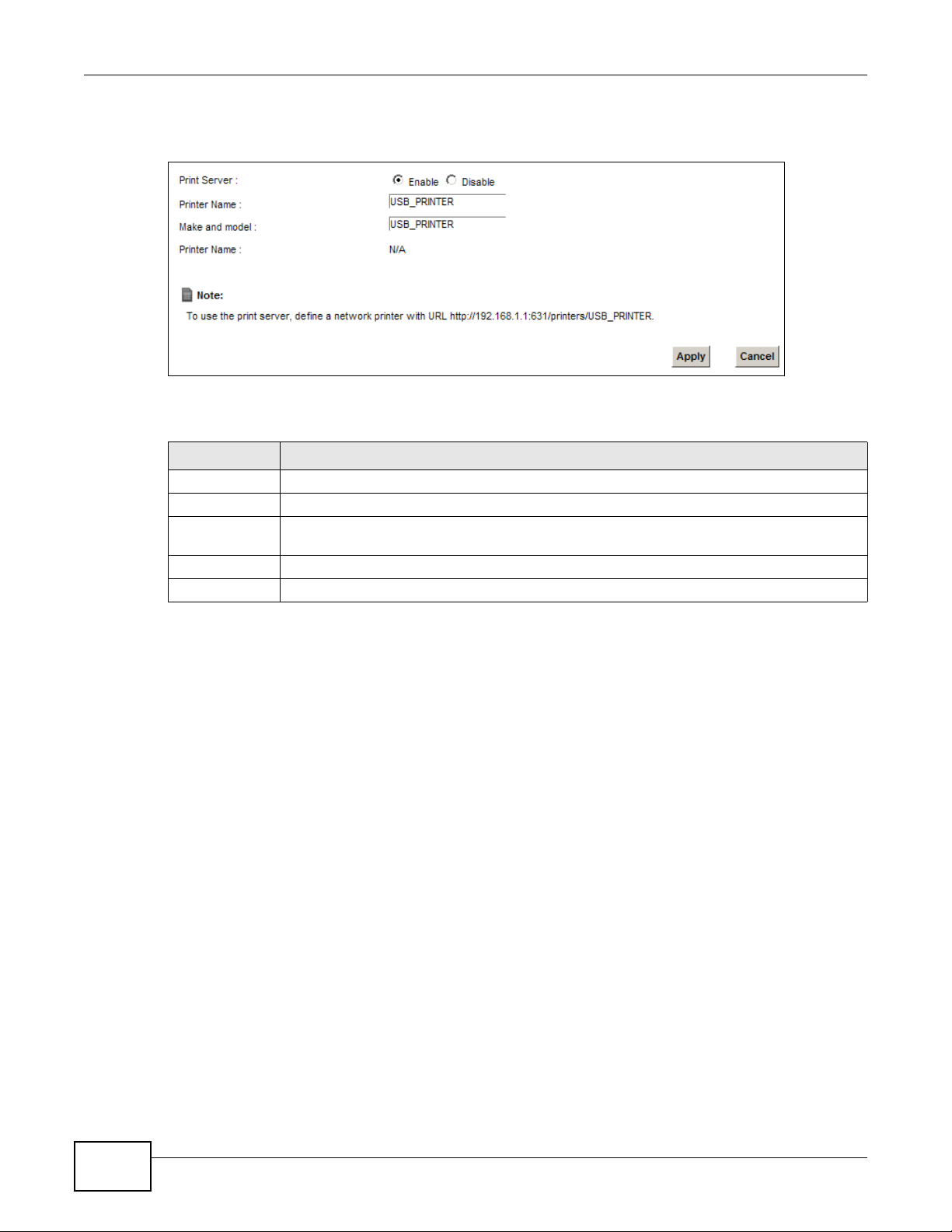
To access this screen, click Network Setting > USB Service > Printer Server.
Figure 101 Network Setting > USB Service > Printer Server
The following table describes the labels in this menu.
Table 73 Network Setting > USB Service > Print Server
LABEL DESCRIPTION
Printer Server Select Enable to have the Device share a USB printer.
Printer Name Enter the name of the printer.
Make and
model
Enter the manufacturer and model number of the printer.
Apply Click Apply to save your changes.
Cancel Click Cancel to restore your previously saved settings.
VMG4380-B10A / VMG4325-B10A User’s Guide 209
CHAPTER 15
Firewall
15.1 Overview
This chapter shows you how to enable and configure the Device’s security settings. Use the firewall
to protect your Device and network from attacks by hackers on the Internet and control access to
it. By default the firewall:
• allows traffic that originates from your LAN computers to go to all other networks.
• blocks traffic that originates on other networks from going to the LAN.
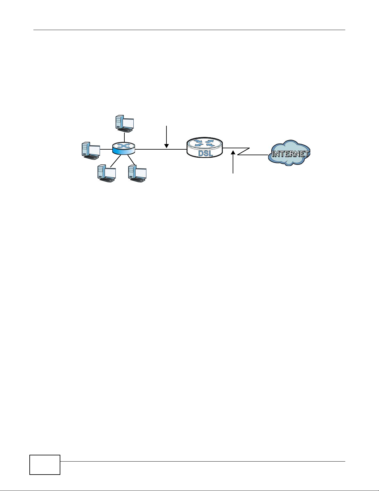
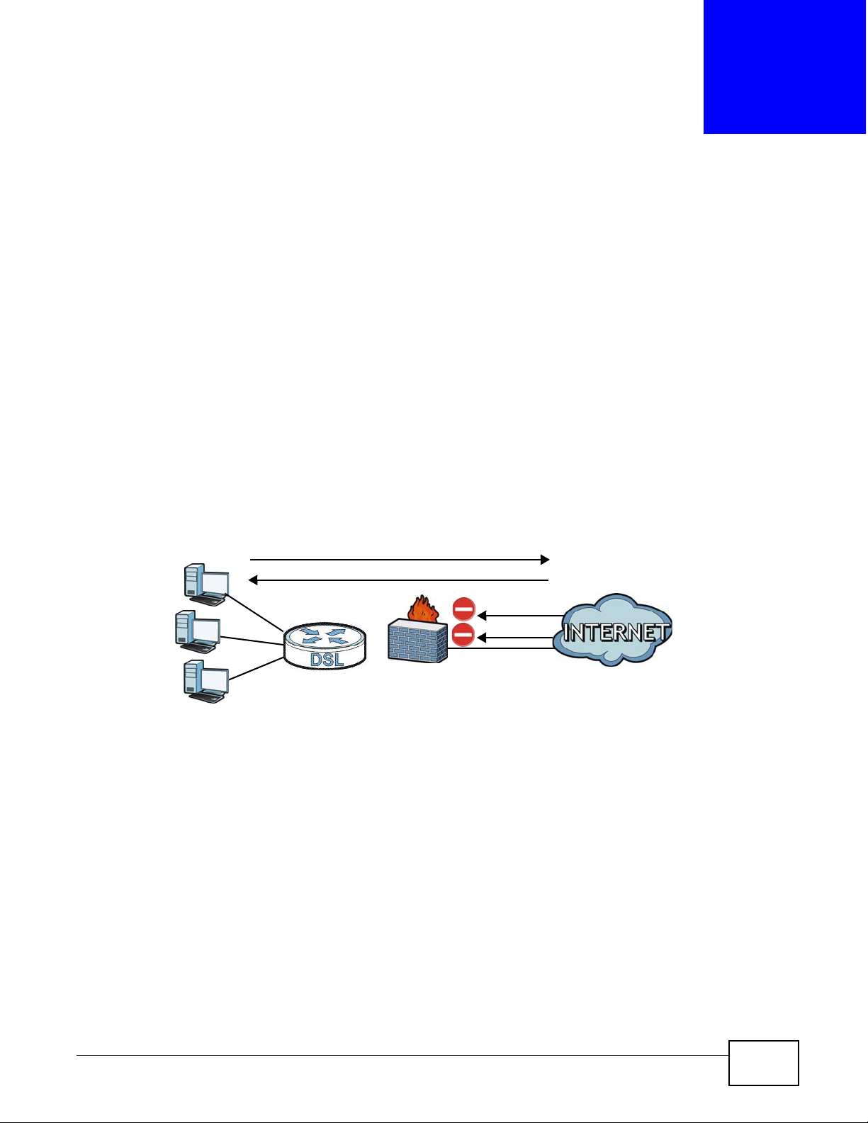
The following figure illustrates the default firewall action. User A can initiate an IM (Instant
Messaging) session from the LAN to the WAN (1). Return traffic for this session is also allowed (2).
However other traffic initiated from the WAN is blocked (3 and 4).
Figure 102 Default Firewall Action
15.1.1 What You Can Do in this Chapter
• Use the General screen to configure the security level of the firewall on the Device (Section 15.2
on page 211).
• Use the Service screen to add or remove predefined Internet services and configure firewall
rules (Section 15.3 on page 211).
• Use the Access Control screen to view and configure incoming/outgoing filtering rules (Section
15.4 on page 213).
• Use the DoS screen to activate protection against Denial of Service (DoS) attacks (Section 15.5
on page 216).
WAN
LAN
3
4
1
2
A

Chapter 15 Firewall
VMG4380-B10A / VMG4325-B10A User’s Guide
210
15.1.2 What You Need to Know
SYN Attack
A SYN attack floods a targeted system with a series of SYN packets. Each packet causes the
targeted system to issue a SYN-ACK response. While the targeted system waits for the ACK that
follows the SYN-ACK, it queues up all outstanding SYN-ACK responses on a backlog queue. SYNACKs are moved off the queue only when an ACK comes back or when an internal timer terminates
the three-way handshake. Once the queue is full, the system will ignore all incoming SYN requests,
making the system unavailable for legitimate users.
DoS
Denials of Service (DoS) attacks are aimed at devices and networks with a connection to the
Internet. Their goal is not to steal information, but to disable a device or network so users no longer
have access to network resources. The ZyXEL Device is pre-configured to automatically detect and
thwart all known DoS attacks.
DDoS
A DDoS attack is one in which multiple compromised systems attack a single target, thereby
causing denial of service for users of the targeted system.
LAND Attack
In a LAND attack, hackers flood SYN packets into the network with a spoofed source IP address of
the target system. This makes it appear as if the host computer sent the packets to itself, making
the system unavailable while the target system tries to respond to itself.
Ping of Death
Ping of Death uses a "ping" utility to create and send an IP packet that exceeds the maximum
65,536 bytes of data allowed by the IP specification. This may cause systems to crash, hang or
reboot.
SPI
Stateful Packet Inspection (SPI) tracks each connection crossing the firewall and makes sure it is
valid. Filtering decisions are based not only on rules but also context. For example, traffic from the
WAN may only be allowed to cross the firewall in response to a request from the LAN.

Chapter 15 Firewall
VMG4380-B10A / VMG4325-B10A User’s Guide
211
15.2 The Firewall Screen
Use this screen to set the security level of the firewall on the Device. Firewall rules are grouped
based on the direction of travel of packets to which they apply.
Click Security > Firewall to display the General screen.
Figure 103 Security > Firewall > General
The following table describes the labels in this screen.
15.3 The Service Screen
You can configure customized services and port numbers in the Service screen. For a
comprehensive list of port numbers and services, visit the IANA (Internet Assigned Number
Authority) website. See Appendix F on page 349 for some examples.
Table 74 Security > Firewall > General
LABEL DESCRIPTION
Firewall Select Enable to activate the firewall feature on the Device.
Easy Select Easy to allow LAN to WAN and WAN to LAN packet directions.
Medium Select Medium to allow LAN to WAN but deny WAN to LAN packet directions.
High Select High to deny LAN to WAN and WAN to LAN packet directions.
Apply Click Apply to save your changes.
Cancel Click Cancel to restore your previously saved settings.

Chapter 15 Firewall
VMG4380-B10A / VMG4325-B10A User’s Guide
212
Click Security > Firewall > Service to display the following screen.
Figure 104 Security > Firewall > Service
The following table describes the labels in this screen.
15.3.1 Add/Edit a Service
Use this screen to add a customized service rule that you can use in the firewall’s ACL rule
configuration. Click Add new service entry or the edit icon next to an existing service rule in the
Service screen to display the following screen.
Figure 105 Service: Add/Edit
Table 75 Security > Firewall > Service
LABEL DESCRIPTION
Add new
service entry
Click this to add a new service.
Name This is the name of your customized service.
Description This is the description of your customized service.
Ports/Protocol
Number
This shows the IP protocol (TCP, UDP, ICMP, or TCP/UDP) and the port number or range
of ports that defines your customized service. Other and the protocol number displays if the
service uses another IP protocol.
Modify Click the Edit icon to edit the entry.
Click the Delete icon to remove this entry.

Chapter 15 Firewall
VMG4380-B10A / VMG4325-B10A User’s Guide
213
The following table describes the labels in this screen.
15.4 The Access Control Screen
Click Security > Firewall > Access Control to display the following screen. This screen displays a
list of the configured incoming or outgoing filtering rules.
Figure 106 Security > Firewall > Access Control
Table 76 Service: Add/Edit
LABEL DESCRIPTION
Protocol Choose the IP protocol (TCP, UDP, ICMP, or Other) that defines your customized port from
the drop-down list box. Select Other to be able to enter a protocol number.
Source/
Destination Port
These fields are displayed if you select TCP or UDP as the IP port.
Select Single to specify one port only or Range to specify a span of ports that define your
customized service. If you select Any, the service is applied to all ports.
Type a single port number or the range of port numbers that define your customized
service.
Protocol
Number
This field is displayed if you select Other as the protocol.
Enter the protocol number of your customized port.
Add Click this to add the protocol to the Rule List below.
Rule List
Protocol This is the IP port (TCP, UDP, ICMP, or Other) that defines your customized port.
Ports/Protocol
Number
For TCP, UDP, ICMP, or TCP/UDP protocol rules this shows the port number or range that
defines the custom service. For other IP protocol rules this shows the protocol number.
Modify Click the Delete icon to remove the rule.
Service Name Enter a unique name (up to 32 printable English keyboard characters, including spaces) for
your customized port.
Service
Description
Enter a description for your customized port.
Apply Click Apply to save your changes.
Cancel Click Cancel to exit this screen without saving.

Chapter 15 Firewall
VMG4380-B10A / VMG4325-B10A User’s Guide
214
The following table describes the labels in this screen.
Table 77 Security > Firewall > Access Control
LABEL DESCRIPTION
DoS Protection DoS (Denial of Service) attacks can flood your Internet connection with invalid packets and
connection requests, using so much bandwidth and so many resources that Internet access
becomes unavailable.
Select the Enable check box to enable protection against DoS attacks.
Add new ACL
rule
Click this to go to add a filter rule for incoming or outgoing IP traffic.
# This is the index number of the entry.
Name This displays the name of the rule.
Src IP This displays the source IP addresses to which this rule applies. Please note that a blank
source address is equivalent to Any.
Dst IP This displays the destination IP addresses to which this rule applies. Please note that a
blank destination address is equivalent to Any.
Service This displays the transport layer protocol that defines the service and the direction of traffic
to which this rule applies.
Action This field displays whether the rule silently discards packets (DROP), discards packets and
sends a TCP reset packet or an ICMP destination-unreachable message to the sender
(REJECT) or allows the passage of packets (ACCEPT).
Modify Click the Edit icon to edit the rule.
Click the Delete icon to delete an existing rule. Note that subsequent rules move up by one
when you take this action.
Click the Move To icon to change the order of the rule. Enter the number in the # field.

Chapter 15 Firewall
VMG4380-B10A / VMG4325-B10A User’s Guide
215
15.4.1 Add/Edit an ACL Rule
Click Add new ACL rule or the Edit icon next to an existing ACL rule in the Access Control
screen. The following screen displays.
Figure 107 Access Control: Add/Edit
The following table describes the labels in this screen.
Table 78 Access Control: Add/Edit
LABEL DESCRIPTION
Filter Name Enter a descriptive name of up to 16 alphanumeric characters, not including spaces,
underscores, and dashes.
You must enter the filter name to add an ACL rule. This field is read-only if you are editing
the ACL rule.
Order Select the order of the ACL rule.
Select Source
Device
Select the source device to which the ACL rule applies. If you select Specific IP Address,
enter the source IP address in the field below.
Source IP
Address
Enter the source IP address.
Select
Destination
Device
Select the destination device to which the ACL rule applies. If you select Specific IP
Address, enter the destiniation IP address in the field below.
Destination IP
Address
Enter the destination IP address.

Chapter 15 Firewall
VMG4380-B10A / VMG4325-B10A User’s Guide
216
15.5 The DoS Screen
DoS (Denial of Service) attacks can flood your Internet connection with invalid packets and
connection requests, using so much bandwidth and so many resources that Internet access
becomes unavailable.
Use the DoS screen to activate protection against DoS attacks. Click Security > Firewall > DoS
to display the following screen.
Figure 108 Security > Firewall > DoS
IP Type Select whether your IP type is IPv4 or IPv6.
Select Protocol Select the transport layer protocol that defines your customized port from the drop-down
list box. The specific protocol rule sets you add in the Security > Firewall > Service >
Add screen display in this list.
If you want to configure a customized protocol, select Specific Service.
Protocol This field is displayed only when you select Specific Protocol in Select Protocol.
Choose the IP port (TCP/UDP, TCP, UDP, ICMP, or ICMPv6) that defines your customized
port from the drop-down list box.
Custom Source
Port
This field is displayed only when you select Specific Protocol in Select Protocol.
Enter a single port number or the range of port numbers of the source.
Custom
Destination Port
This field is displayed only when you select Specific Protocol in Select Protocol.
Enter a single port number or the range of port numbers of the destination.
Policy Use the drop-down list box to select whether to discard (DROP), deny and send an ICMP
destination-unreachable message to the sender of (REJECT) or allow the passage of
(ACCEPT) packets that match this rule.
Direction Use the drop-down list box to select the direction of traffic to which this rule applies.
Enable Rate
Limit
Select this check box to set a limit on the upstream/downstream transmission rate for the
specified protocol.
Specify how many packets per minute or second the transmission rate is.
Scheduler Rules Select a schedule rule for this ACL rule form the drop-down list box. You can configure a
new schedule rule by click Add New Rule. This will bring you to the Security > Scheduler
Rules screen.
Apply Click Apply to save your changes.
Cancel Click Cancel to exit this screen without saving.
Table 78 Access Control: Add/Edit (continued)
LABEL DESCRIPTION

Chapter 15 Firewall
VMG4380-B10A / VMG4325-B10A User’s Guide
217
The following table describes the labels in this screen.
Table 79 Security > Firewall > DoS
LABEL DESCRIPTION
DoS Protection
Blocking
Select Enable to enable protection against DoS attacks.
Deny Ping
Response
Select Enable to block ping request packets.
Apply Click Apply to save your changes.
Cancel Click Cancel to exit this screen without saving.

Chapter 15 Firewall
VMG4380-B10A / VMG4325-B10A User’s Guide
218

VMG4380-B10A / VMG4325-B10A User’s Guide 219
CHAPTER 16
MAC Filter
16.1 Overview
You can configure the Device to permit access to clients based on their MAC addresses in the MAC
Filter screen. This applies to wired and wireless connections. Every Ethernet device has a unique
MAC (Media Access Control) address. The MAC address is assigned at the factory and consists of six
pairs of hexadecimal characters, for example, 00:A0:C5:00:00:02. You need to know the MAC
addresses of the devices to configure this screen.
16.2 The MAC Filter Screen
Use this screen to allow wireless and LAN clients access to the Device. Click Security > MAC Filter.
The screen appears as shown.
Figure 109 Security > MAC Filter

Chapter 16 MAC Filter
VMG4380-B10A / VMG4325-B10A User’s Guide
220
The following table describes the labels in this screen.
Table 80 Security > MAC Filter
LABEL DESCRIPTION
MAC Address Filter Select Enable to activate the MAC filter function.
Set This is the index number of the MAC address.
Allow Select Allow to permit access to the Device. MAC addresses not listed will be denied
access to the Device.
If you clear this, the MAC Address field for this set clears.
Host name Enter the host name of the wireless or LAN clients that are allowed access to the
Device.
MAC Address Enter the MAC addresses of the wireless or LAN clients that are allowed access to the
Device in these address fields. Enter the MAC addresses in a valid MAC address format,
that is, six hexadecimal character pairs, for example, 12:34:56:78:9a:bc.
Apply Click Apply to save your changes.
Cancel Click Cancel to restore your previously saved settings.

VMG4380-B10A / VMG4325-B10A User’s Guide 221
CHAPTER 17
Parental Control
17.1 Overview
Parental control allows you to block web sites with the specific URL. You can also define time
periods and days during which the Device performs parental control on a specific user.
17.2 The Parental Control Screen
Use this screen to enable parental control, view the parental control rules and schedules.
Click Security > Parental Control to open the following screen.
Figure 110 Security > Parental Control
The following table describes the fields in this screen.
Table 81 Security > Parental Control
LABEL DESCRIPTION
Parental
Control
Select Enable to activate parental control.
Add new PCP Click this if you want to configure a new parental control rule.
# This shows the index number of the rule.
Status This indicates whether the rule is active or not.
A yellow bulb signifies that this rule is active. A gray bulb signifies that this rule is not active.
PCP Name This shows the name of the rule.
Home Network
User (MAC)
This shows the MAC address of the LAN user’s computer to which this rule applies.

Chapter 17 Parental Control
VMG4380-B10A / VMG4325-B10A User’s Guide
222
17.2.1 Add/Edit a Parental Control Rule
Click Add new PCP in the Parental Control screen to add a new rule or click the Edit icon next to
an existing rule to edit it. Use this screen to configure a restricted access schedule and/or URL
filtering settings to block the users on your network from accessing certain web sites.
Figure 111 Parental Control Rule: Add/Edit
Internet Access
Schedule
This shows the day(s) and time on which parental control is enabled.
Network
Service
This shows whether the network service is configured. If not, None will be shown.
Website Block This shows whether the website block is configured. If not, None will be shown.
Modify Click the Edit icon to go to the screen where you can edit the rule.
Click the Delete icon to delete an existing rule.
Apply Click Apply to save your changes.
Cancel Click Cancel to restore your previously saved settings.
Table 81 Security > Parental Control (continued)
LABEL DESCRIPTION

Chapter 17 Parental Control
VMG4380-B10A / VMG4325-B10A User’s Guide
223
The following table describes the fields in this screen.
Table 82 Parental Control Rule: Add/Edit
LABEL DESCRIPTION
General
Active Select the checkbox to activate this parental control rule.
Parental
Control Profile
Name
Enter a descriptive name for the rule.
Home Network
User
Select the LAN user that you want to apply this rule to from the drop-down list box. If you
select Custom, enter the LAN user’s MAC address. If you select All, the rule applies to all
LAN users.
Internet Access Schedule
Day Select check boxes for the days that you want the Device to perform parental control.
Time Drag the time bar to define the time that the LAN user is allowed access.
Network Service
Network
Service Setting
If you select Block, the Device prohibits the users from viewing the Web sites with the URLs
listed below.
If you select Allow, the Device blocks access to all URLs except ones listed below.
Add new
service
Click this to show a screen in which you can add a new service rule. You can configure the
Service Name, Protocol, and Name of the new rule.
# This shows the index number of the rule. Select the checkbox next to the rule to activate it.
Service Name This shows the name of the rule.
Protocol:Port This shows the protocol and the port of the rule.
Modify Click the Edit icon to go to the screen where you can edit the rule.
Click the Delete icon to delete an existing rule.
Blocked Site/
URL Keyword
Click Add to show a screen to enter the URL of web site or URL keyword to which the Device
blocks access. Click Delete to remove it.
Apply Click this button to save your settings back to the Device.
Cancel Click Cancel to restore your previously saved settings.

Chapter 17 Parental Control
VMG4380-B10A / VMG4325-B10A User’s Guide
224

VMG4380-B10A / VMG4325-B10A User’s Guide 225
CHAPTER 18
Scheduler Rules
18.1 Overview
You can define time periods and days during which the Device performs scheduled rules of certain
features (such as Firewall Access Control, Parental Control) on a specific user in the Scheduler Rules
screen.
18.2 The Scheduler Rules Screen
Use this screen to view, add, or edit time schedule rules.
Click Security > Scheduler Rules to open the following screen.
Figure 112 Security > Scheduler Rules
The following table describes the fields in this screen.
Table 83 Security > Scheduler Rules
LABEL DESCRIPTION
Add new rule Click this to create a new rule.
# This is the index number of the entry.
Rule Name This shows the name of the rule.
Day This shows the day(s) on which this rule is enabled.
Time This shows the period of time on which this rule is enabled.
Description This shows the description of this rule.
Modify Click the Edit icon to edit the schedule.
Click the Delete icon to delete a scheduler rule.
Note: You cannot delete a scheduler rule once it is applied to a certain feature.

Chapter 18 Scheduler Rules
VMG4380-B10A / VMG4325-B10A User’s Guide
226
18.2.1 Add/Edit a Schedule
Click the Add button in the Scheduler Rules screen or click the Edit icon next to a schedule rule
to open the following screen. Use this screen to configure a restricted access schedule for a specific
user on your network.
Figure 113 Scheduler Rules: Add/Edit
The following table describes the fields in this screen.
Table 84 Scheduler Rules: Add/Edit
LABEL DESCRIPTION
Rule Name Enter a name (up to 31 printable English keyboard characters, not including spaces) for this
schedule.
Day Select check boxes for the days that you want the Device to perform this scheduler rule.
Time if Day
Range
Enter the time period of each day, in 24-hour format, during which parental control will be
enforced.
Description Enter a description for this scheduler rule.
Apply Click Apply to save your changes.
Cancel Click Cancel to exit this screen without saving.

VMG4380-B10A / VMG4325-B10A User’s Guide 227
CHAPTER 19
Certificates
19.1 Overview
The Device can use certificates (also called digital IDs) to authenticate users. Certificates are based
on public-private key pairs. A certificate contains the certificate owner’s identity and public key.
Certificates provide a way to exchange public keys for use in authentication.
19.1.1 What You Can Do in this Chapter
• The Local Certificates screen lets you generate certification requests and import the Device's
CA-signed certificates (Section 19.4 on page 231).
• The Trusted CA screen lets you save the certificates of trusted CAs to the Device (Section 19.4
on page 231).
19.2 What You Need to Know
The following terms and concepts may help as you read through this chapter.
Certification Authority
A Certification Authority (CA) issues certificates and guarantees the identity of each certificate
owner. There are commercial certification authorities like CyberTrust or VeriSign and government
certification authorities. The certification authority uses its private key to sign certificates. Anyone
can then use the certification authority's public key to verify the certificates. You can use the Device
to generate certification requests that contain identifying information and public keys and then send
the certification requests to a certification authority.

Chapter 19 Certificates
VMG4380-B10A / VMG4325-B10A User’s Guide
228
19.3 The Local Certificates Screen
Click Security > Certificates to open the Local Certificates screen. This is the Device’s summary
list of certificates and certification requests.
Figure 114 Security > Certificates > Local Certificates
The following table describes the labels in this screen.
Table 85 Security > Certificates > Local Certificates
LABEL DESCRIPTION
Private Key is
protected by a
password?
Select the checkbox and enter the private key into the text box to store it on the Device.
The private key should not exceed 63 ASCII characters (not including spaces).
Browse... Click this to find the certificate file you want to upload.
Import Certificate Click this button to save the certificate that you have enrolled from a certification
authority from your computer to the Device.
Create Certificate
Request
Click this button to go to the screen where you can have the Device generate a
certification request.
Current File This field displays the name used to identify this certificate. It is recommended that you
give each certificate a unique name.
Subject This field displays identifying information about the certificate’s owner, such as CN
(Common Name), OU (Organizational Unit or department), O (Organization or company)
and C (Country). It is recommended that each certificate have unique subject
information.
Issuer This field displays identifying information about the certificate’s issuing certification
authority, such as a common name, organizational unit or department, organization or
company and country.
Valid From This field displays the date that the certificate becomes applicable. The text displays in
red and includes a Not Yet Valid! message if the certificate has not yet become
applicable.
Valid To This field displays the date that the certificate expires. The text displays in red and
includes an Expiring! or Expired! message if the certificate is about to expire or has
already expired.
Modify Click the View icon to open a screen with an in-depth list of information about the
certificate (or certification request).
For a certification request, click Load Signed to import the signed certificate.
Click the Remove icon to delete the certificate (or certification request). You cannot
delete a certificate that one or more features is configured to use.

Chapter 19 Certificates
VMG4380-B10A / VMG4325-B10A User’s Guide
229
19.3.1 Create Certificate Request
Click Security > Certificates > Local Certificates and then Create Certificate Request to
open the following screen. Use this screen to have the Device generate a certification request.
Figure 115 Create Certificate Request
The following table describes the labels in this screen.
After you click Apply, the following screen displays to notify you that you need to get the certificate
request signed by a Certificate Authority. If you already have, click Load_Signed to import the
signed certificate into the Device. Otherwise click Back to return to the Local Certificates screen.
Table 86 Create Certificate Request
LABEL DESCRIPTION
Certificate
Name
Type up to 63 ASCII characters (not including spaces) to identify this certificate.
Common Name Select Auto to have the Device configure this field automatically. Or select Customize to
enter it manually.
Type the IP address (in dotted decimal notation), domain name or e-mail address in the field
provided. The domain name or e-mail address can be up to 63 ASCII characters. The
domain name or e-mail address is for identification purposes only and can be any string.
Organization
Name
Type up to 63 characters to identify the company or group to which the certificate owner
belongs. You may use any character, including spaces, but the Device drops trailing spaces.
State/Province
Name
Type up to 32 characters to identify the state or province where the certificate owner is
located. You may use any character, including spaces, but the Device drops trailing spaces.
Country/Region
Name
Select a country to identify the nation where the certificate owner is located.
Apply Click Apply to save your changes.
Cancel Click Cancel to exit this screen without saving.

Chapter 19 Certificates
VMG4380-B10A / VMG4325-B10A User’s Guide
230
Figure 116 Certificate Request Created
19.3.2 Load Signed Certificate
After you create a certificate request and have it signed by a Certificate Authority, in the Local
Certificates screen click the certificate request’s Load Signed icon to import the signed certificate
into the Device.
Note: You must remove any spaces from the certificate’s filename before you can import
it.
Figure 117 Load Signed Certificate

Chapter 19 Certificates
VMG4380-B10A / VMG4325-B10A User’s Guide
231
The following table describes the labels in this screen.
19.4 The Trusted CA Screen
Click Security > Certificates > Trusted CA to open the following screen. This screen displays a
summary list of certificates of the certification authorities that you have set the Device to accept as
trusted. The Device accepts any valid certificate signed by a certification authority on this list as
being trustworthy; thus you do not need to import any certificate that is signed by one of these
certification authorities.
Figure 118 Security > Certificates > Trusted CA
The following table describes the fields in this screen.
Table 87 Load Signed Certificate
LABEL DESCRIPTION
Certificate
Name
This is the name of the signed certificate.
Certificate Copy and paste the signed certificate into the text box to store it on the Device.
Apply Click Apply to save your changes.
Cancel Click Cancel to exit this screen without saving.
Table 88 Security > Certificates > Trusted CA
LABEL DESCRIPTION
Import
Certificate
Click this button to open a screen where you can save the certificate of a certification
authority that you trust to the Device.
# This is the index number of the entry.
Name This field displays the name used to identify this certificate.
Subject This field displays information that identifies the owner of the certificate, such as Common
Name (CN), OU (Organizational Unit or department), Organization (O), State (ST) and
Country (C). It is recommended that each certificate have unique subject information.
Type This field displays general information about the certificate. ca means that a Certification
Authority signed the certificate.
Modify Click the View icon to open a screen with an in-depth list of information about the
certificate (or certification request).
Click the Remove button to delete the certificate (or certification request). You cannot
delete a certificate that one or more features is configured to use.

Chapter 19 Certificates
VMG4380-B10A / VMG4325-B10A User’s Guide
232
19.4.1 View Trusted CA Certificate
Click the View icon in the Trusted CA screen to open the following screen. Use this screen to view
in-depth information about the certification authority’s certificate.
Figure 119 Trusted CA: View
The following table describes the fields in this screen.
Table 89 Trusted CA: View
LABEL DESCRIPTION
Name This field displays the identifying name of this certificate.
Type This field displays general information about the certificate. ca means that a Certification
Authority signed the certificate.
Subject This field displays information that identifies the owner of the certificate, such as Common
Name (CN), Organizational Unit (OU), Organization (O) and Country (C).
Certificate This read-only text box displays the certificate in Privacy Enhanced Mail (PEM) format. PEM
uses base 64 to convert the binary certificate into a printable form.
You can copy and paste the certificate into an e-mail to send to friends or colleagues or you
can copy and paste the certificate into a text editor and save the file on a management
computer for later distribution (via floppy disk for example).
Back Click Back to return to the previous screen.

Chapter 19 Certificates
VMG4380-B10A / VMG4325-B10A User’s Guide
233
19.4.2 Import Trusted CA Certificate
Click the Import Certificate button in the Trusted CA screen to open the following screen. The
Device trusts any valid certificate signed by any of the imported trusted CA certificates.
Figure 120 Trusted CA: Import Certificate
The following table describes the fields in this screen.
Table 90 Trusted CA: Import Certificate
LABEL DESCRIPTION
Certificate File
Path
Type in the location of the certificate you want to upload in this field or click Browse ... to
find it.
Enable Trusted
CA for 802.1x
Authentication
If you select this checkbox, the trusted CA will be used for 802.1x authentication. The
selected trusted CA will be displayed in the Network Setting > Broadband > 802.1x:
Edit screen.
Certificate Copy and paste the certificate into the text box to store it on the Device.
OK Click OK to save your changes.
Cancel Click Cancel to exit this screen without saving.

Chapter 19 Certificates
VMG4380-B10A / VMG4325-B10A User’s Guide
234

VMG4380-B10A / VMG4325-B10A User’s Guide 235
CHAPTER 20
Log
20.1 Overview
The web configurator allows you to choose which categories of events and/or alerts to have the
Device log and then display the logs or have the Device send them to an administrator (as e-mail)
or to a syslog server.
20.1.1 What You Can Do in this Chapter
• Use the System Log screen to see the system logs (Section 20.2 on page 236).
• Use the Security Log screen to see the security-related logs for the categories that you select
(Section 20.3 on page 237).
20.1.2 What You Need To Know
The following terms and concepts may help as you read this chapter.
Alerts and Logs
An alert is a type of log that warrants more serious attention. They include system errors, attacks
(access control) and attempted access to blocked web sites. Some categories such as System
Errors consist of both logs and alerts. You may differentiate them by their color in the View Log
screen. Alerts display in red and logs display in black.
Syslog Overview
The syslog protocol allows devices to send event notification messages across an IP network to
syslog servers that collect the event messages. A syslog-enabled device can generate a syslog
message and send it to a syslog server.
Syslog is defined in RFC 3164. The RFC defines the packet format, content and system log related
information of syslog messages. Each syslog message has a facility and severity level. The syslog
facility identifies a file in the syslog server. Refer to the documentation of your syslog program for
details. The following table describes the syslog severity levels.
Table 91 Syslog Severity Levels
CODE SEVERITY
0 Emergency: The system is unusable.
1 Alert: Action must be taken immediately.
2 Critical: The system condition is critical.
3 Error: There is an error condition on the system.
4 Warning: There is a warning condition on the system.

Chapter 20 Log
VMG4380-B10A / VMG4325-B10A User’s Guide
236
20.2 The System Log Screen
Use the System Log screen to see the system logs. Click System Monitor > Log to open the
System Log screen.
Figure 121 System Monitor > Log > System Log
The following table describes the fields in this screen.
5 Notice: There is a normal but significant condition on the system.
6 Informational: The syslog contains an informational message.
7 Debug: The message is intended for debug-level purposes.
Table 91 Syslog Severity Levels
CODE SEVERITY
Table 92 System Monitor > Log > System Log
LABEL DESCRIPTION
Level Select a severity level from the drop-down list box. This filters search results according to
the severity level you have selected. When you select a severity, the Device searches
through all logs of that severity or higher.
Category Select the type of logs to display.
Clear Log Click this to delete all the logs.
Refresh Click this to renew the log screen.
Export Log Click this to export the selected log(s).
Email Log Now Click this to send the log file(s) to the E-mail address you specify in the Maintenance >
Logs Setting screen.
System Log
# This field is a sequential value and is not associated with a specific entry.
Time This field displays the time the log was recorded.
Facility The log facility allows you to send logs to different files in the syslog server. Refer to the
documentation of your syslog program for more details.
Level This field displays the severity level of the logs that the device is to send to this syslog
server.
Messages This field states the reason for the log.

Chapter 20 Log
VMG4380-B10A / VMG4325-B10A User’s Guide
237
20.3 The Security Log Screen
Use the Security Log screen to see the security-related logs for the categories that you select.
Click System Monitor > Log > Security Log to open the following screen.
Figure 122 System Monitor > Log > Security Log
The following table describes the fields in this screen.
Table 93 System Monitor > Log > Security Log
LABEL DESCRIPTION
Level Select a severity level from the drop-down list box. This filters search results according to
the severity level you have selected. When you select a severity, the Device searches
through all logs of that severity or higher.
Category Select the type of logs to display.
Clear Log Click this to delete all the logs.
Refresh Click this to renew the log screen.
Export Log Click this to export the selected log(s).
Email Log Now Click this to send the log file(s) to the E-mail address you specify in the Maintenance >
Logs Setting screen.
# This field is a sequential value and is not associated with a specific entry.
Time This field displays the time the log was recorded.
Facility The log facility allows you to send logs to different files in the syslog server. Refer to the
documentation of your syslog program for more details.
Level This field displays the severity level of the logs that the device is to send to this syslog
server.
Messages This field states the reason for the log.

Chapter 20 Log
VMG4380-B10A / VMG4325-B10A User’s Guide
238

VMG4380-B10A / VMG4325-B10A User’s Guide 239
CHAPTER 21
Traffic Status
21.1 Overview
Use the Traffic Status screens to look at network traffic status and statistics of the WAN and LAN
interfaces.
21.1.1 What You Can Do in this Chapter
• Use the WAN screen to view the WAN traffic statistics (Section 21.2 on page 239).
• Use the LAN screen to view the LAN traffic statistics (Section 21.3 on page 241).
21.2 The WAN Status Screen
Click System Monitor > Traffic Status to open the WAN screen. The figure in this screen shows
the number of bytes received and sent on the Device.
Figure 123 System Monitor > Traffic Status > WAN

Chapter 21 Traffic Status
VMG4380-B10A / VMG4325-B10A User’s Guide
240
The following table describes the fields in this screen.
Table 94 System Monitor > Traffic Status > WAN
LABEL DESCRIPTION
Connected
Interface
This shows the name of the WAN interface that is currently connected.
Packets Sent
Data This indicates the number of transmitted packets on this interface.
Error This indicates the number of frames with errors transmitted on this interface.
Drop This indicates the number of outgoing packets dropped on this interface.
Packets Received
Data This indicates the number of received packets on this interface.
Error This indicates the number of frames with errors received on this interface.
Drop This indicates the number of received packets dropped on this interface.
more...hide
more
Click more... to show more information. Click hide more to hide them.
Disabled
Interface
This shows the name of the WAN interface that is currently disconnected.
Packets Sent
Data This indicates the number of transmitted packets on this interface.
Error This indicates the number of frames with errors transmitted on this interface.
Drop This indicates the number of outgoing packets dropped on this interface.
Packets Received
Data This indicates the number of received packets on this interface.
Error This indicates the number of frames with errors received on this interface.
Drop This indicates the number of received packets dropped on this interface.

Chapter 21 Traffic Status
VMG4380-B10A / VMG4325-B10A User’s Guide
241
21.3 The LAN Status Screen
Click System Monitor > Traffic Status > LAN to open the following screen. The figure in this
screen shows the interface that is currently connected on the Device.
Figure 124 System Monitor > Traffic Status > LAN
The following table describes the fields in this screen.
Table 95 System Monitor > Traffic Status > LAN
LABEL DESCRIPTION
Refresh Interval Select how often you want the Device to update this screen.
Interface This shows the LAN or WLAN interface.
Bytes Sent This indicates the number of bytes transmitted on this interface.
more...hide
more
Click more... to show more information. Click hide more to hide them.
Interface This shows the LAN or WLAN interface.
Sent (Packets)
Data This indicates the number of transmitted packets on this interface.
Error This indicates the number of frames with errors transmitted on this interface.
Drop This indicates the number of outgoing packets dropped on this interface.
Received (Packets)
Data This indicates the number of received packets on this interface.
Error This indicates the number of frames with errors received on this interface.
Drop This indicates the number of received packets dropped on this interface.

Chapter 21 Traffic Status
VMG4380-B10A / VMG4325-B10A User’s Guide
242

VMG4380-B10A / VMG4325-B10A User’s Guide 243
CHAPTER 22
ARP Table
22.1 Overview
Address Resolution Protocol (ARP) is a protocol for mapping an Internet Protocol address (IP
address) to a physical machine address, also known as a Media Access Control or MAC address, on
the local area network.
An IP (version 4) address is 32 bits long. In an Ethernet LAN, MAC addresses are 48 bits long. The
ARP Table maintains an association between each MAC address and its corresponding IP address.
22.1.1 How ARP Works
When an incoming packet destined for a host device on a local area network arrives at the device,
the device's ARP program looks in the ARP Table and, if it finds the address, sends it to the device.
If no entry is found for the IP address, ARP broadcasts the request to all the devices on the LAN.
The device fills in its own MAC and IP address in the sender address fields, and puts the known IP
address of the target in the target IP address field. In addition, the device puts all ones in the target
MAC field (FF.FF.FF.FF.FF.FF is the Ethernet broadcast address). The replying device (which is either
the IP address of the device being sought or the router that knows the way) replaces the broadcast
address with the target's MAC address, swaps the sender and target pairs, and unicasts the answer
directly back to the requesting machine. ARP updates the ARP Table for future reference and then
sends the packet to the MAC address that replied.
22.2 ARP Table Screen
Use the ARP table to view IP-to-MAC address mapping(s). To open this screen, click System
Monitor > ARP Table.
Figure 125 System Monitor > ARP Table
The following table describes the labels in this screen.
Table 96 System Monitor > ARP Table
LABEL DESCRIPTION
# This is the ARP table entry number.
IP Address This is the learned IP address of a device connected to a port.

Chapter 22 ARP Table
VMG4380-B10A / VMG4325-B10A User’s Guide
244
MAC Address This is the MAC address of the device with the listed IP address.
Device This is the type of interface used by the device. You can click on the device type to go to its
configuration screen.
Table 96 System Monitor > ARP Table (continued)
LABEL DESCRIPTION

VMG4380-B10A / VMG4325-B10A User’s Guide 245
CHAPTER 23
Routing Table
23.1 Overview
Routing is based on the destination address only and the Device takes the shortest path to forward
a packet.
23.2 The Routing Table Screen
Click System Monitor > Routing Table to open the following screen.
Figure 126 System Monitor > Routing Table
The following table describes the labels in this screen.
Table 97 System Monitor > Routing Table
LABEL DESCRIPTION
Destination This indicates the destination IP address of this route.
Gateway This indicates the IP address of the gateway that helps forward this route’s traffic.
Subnet Mask This indicates the destination subnet mask of this route.
Flag This indicates the route status.
U-Up: The route is up.
!-Reject: The route is blocked and will force a route lookup to fail.
G-Gateway: The route uses a gateway to forward traffic.
H-Host: The target of the route is a host.
R-Reinstate: The route is reinstated for dynamic routing.
D-Dynamic (redirect): The route is dynamically installed by a routing daemon or redirect.
M-Modified (redirect): The route is modified from a routing daemon or redirect.
Metric The metric represents the "cost of transmission". A router determines the best route for
transmission by choosing a path with the lowest "cost". The smaller the number, the lower
the "cost".

Chapter 23 Routing Table
VMG4380-B10A / VMG4325-B10A User’s Guide
246
Service This indicates the name of the service used to forward the route.
Interface This indicates the name of the interface through which the route is forwarded.
br0 indicates the LAN interface.
ptm0 indicates the WAN interface using IPoE or in bridge mode.
ppp0 indicates the WAN interface using PPPoE.
Table 97 System Monitor > Routing Table (continued)
LABEL DESCRIPTION

VMG4380-B10A / VMG4325-B10A User’s Guide 247
CHAPTER 24
IGMP Status
24.1 Overview
Use the IGMP Status screens to look at IGMP group status and traffic statistics.
24.2 The IGMP Group Status Screen
Use this screen to look at the current list of multicast groups the Device has joined and which ports
have joined it. To open this screen, click System Monitor > IGMP Group Status.
Figure 127 System Monitor > IGMP Group Status
The following table describes the labels in this screen.
Table 98 System Monitor > IGMP Group Status
LABEL DESCRIPTION
Interface This field displays the name of an interface on the Device that belongs to an IGMP multicast
group.
Multicast Group This field displays the name of the IGMP multicast group to which the interface belongs.
Filter Mode INCLUDE means that only the IP addresses in the Source List get to receive the multicast
group’s traffic.
EXCLUDE means that the IP addresses in the Source List are not allowed to receive the
multicast group’s traffic but other IP addresses can.
Source List This is the list of IP addresses that are allowed or not allowed to receive the multicast
group’s traffic depending on the filter mode.

Chapter 24 IGMP Status
VMG4380-B10A / VMG4325-B10A User’s Guide
248

VMG4380-B10A / VMG4325-B10A User’s Guide 249
CHAPTER 25
xDSL Statistics
25.1 The xDSL Statistics Screen
Use this screen to view detailed DSL statistics. Click System Monitor > xDSL Statistics to open
the following screen.
Figure 128 System Monitor > xDSL Statistics

Chapter 25 xDSL Statistics
VMG4380-B10A / VMG4325-B10A User’s Guide
250
The following table describes the labels in this screen.
Table 99 Status > xDSL Statistics
LABEL DESCRIPTION
Refresh Interval Select the time interval for refreshing statistics.
Line Select which DSL line’s statistics you want to display.
xDSL Training
Status
This displays the current state of setting up the DSL connection.
Mode This displays the ITU standard used for this connection.
Traffic Type This displays the type of traffic the DSL port is sending and receiving. Inactive displays if
the DSL port is not currently sending or receiving traffic.
Link Uptime This displays how long the port has been running (or connected) since the last time it was
started.
xDSL Port Details
Upstream These are the statistics for the traffic direction going out from the port to the service
provider.
Downstream These are the statistics for the traffic direction coming into the port from the service
provider.
Line Rate These are the data transfer rates at which the port is sending and receiving data.
Actual Net Data
Rate
These are the rates at which the port is sending and receiving the payload data without
transport layer protocol headers and traffic.
Trellis Coding This displays whether or not the port is using Trellis coding for traffic it is sending and
receiving. Trellis coding helps to reduce the noise in ADSL transmissions. Trellis may reduce
throughput but it makes the connection more stable.
SNR Margin This is the upstream and downstream Signal-to-Noise Ratio margin (in dB). A DMT sub-
carrier’s SNR is the ratio between the received signal power and the received noise power.
The signal-to-noise ratio margin is the maximum that the received noise power could
increase with the system still being able to meet its transmission targets.
Actual Delay This is the upstream and downstream interleave delay. It is the wait (in milliseconds) that
determines the size of a single block of data to be interleaved (assembled) and then
transmitted. Interleave delay is used when transmission error correction (Reed- Solomon)
is necessary due to a less than ideal telephone line. The bigger the delay, the bigger the
data block size, allowing better error correction to be performed.
Transmit Power This is the upstream and downstream far end actual aggregate transmit power (in dBm).
Upstream is how much power the port is using to transmit to the service provider.
Downstream is how much port the service provider is using to transmit to the port.
Receive Power Upstream is how much power the service provider is receiving from the port. Downstream
is how much power the port is receiving from the service provider.
Actual INP Sudden spikes in the line’s level of external noise (impulse noise) can cause errors and
result in lost packets. This could especially impact the quality of multimedia traffic such as
voice or video. Impulse noise protection (INP) provides a buffer to allow for correction of
errors caused by error correction to deal with this. The number of DMT (Discrete MultiTone) symbols shows the level of impulse noise protection for the upstream and
downstream traffic. A higher symbol value provides higher error correction capability, but it
causes overhead and higher delay which may increase error rates in received multimedia
data.
Total Attenuation This is the upstream and downstream line attenuation, measured in decibels (dB). This
attenuation is the difference between the power transmitted at the near-end and the power
received at the far-end. Attenuation is affected by the channel characteristics (wire gauge,
quality, condition and length of the physical line).
Attainable Net
Data Rate
These are the highest theoretically possible transfer rates at which the port could send and
receive payload data without transport layer protocol headers and traffic.
xDSL Counters

Chapter 25 xDSL Statistics
VMG4380-B10A / VMG4325-B10A User’s Guide
251
Downstream These are the statistics for the traffic direction coming into the port from the service
provider.
Upstream These are the statistics for the traffic direction going out from the port to the service
provider.
FEC This is the number of Far End Corrected blocks.
CRC This is the number of Cyclic Redundancy Checks.
ES This is the number of Errored Seconds meaning the number of seconds containing at least
one errored block or at least one defect.
SES This is the number of Severely Errored Seconds meaning the number of seconds containing
30% or more errored blocks or at least one defect. This is a subset of ES.
UAS This is the number of UnAvailable Seconds.
LOS This is the number of Loss Of Signal seconds.
LOF This is the number of Loss Of Frame seconds.
LOM This is the number of Loss of Margin seconds.
Table 99 Status > xDSL Statistics (continued)
LABEL DESCRIPTION

Chapter 25 xDSL Statistics
VMG4380-B10A / VMG4325-B10A User’s Guide
252

VMG4380-B10A / VMG4325-B10A User’s Guide 253
CHAPTER 26
User Account
26.1 Overview
In the Users Account screen, you can change the password of the user account that you used to
log in the Device.
26.2 The User Account Screen
Click Maintenance > User Account to open the following screen.
Figure 129 Maintenance > User Account
The following table describes the labels in this screen.
Table 100 Maintenance > User Account
LABEL DESCRIPTION
User Name This field displays the name of the account that you used to log in the system.
Old Password Type the default password or the existing password you use to access the system in this
field.
New Password Type your new system password (up to 30 characters). Note that as you type a password,
the screen displays a (*) for each character you type. After you change the password, use
the new password to access the Device.
Retype to
confirm
Type the new password again for confirmation.
Apply Click Apply to save your changes.
Cancel Click Cancel to restore your previously saved settings.

Chapter 26 User Account
VMG4380-B10A / VMG4325-B10A User’s Guide
254

VMG4380-B10A / VMG4325-B10A User’s Guide 255
CHAPTER 27
Remote Management
27.1 Overview
Remote Management allows you to manage your Device from a remote location through the
following interfaces:
• LAN
• WAN
• Trust Domain
Note: The Device is managed using the Web Configurator.
27.2 The Remote MGMT Screen
Use this screen to configure through which interface(s) users can use which service(s) to manage
the Device.
Click Maintenance > Remote MGMT to open the following screen.
Figure 130 Maintenance > Remote MGMT

Chapter 27 Remote Management
VMG4380-B10A / VMG4325-B10A User’s Guide
256
The following table describes the fields in this screen.
Table 101 Maintenance > Remote MGMT
LABEL DESCRIPTION
Trust Domain
Status This field displays whether the Trust Domain is active or not.
IP Address Enter the Trust Domain IP address.
Services This is the service you may use to access the Device.
LAN/WLAN Select the Enable check box for the corresponding services that you want to allow access to
the Device from the LAN/WLAN.
WAN Select the Enable check box for the corresponding services that you want to allow access to
the Device from the WAN.
Trust Domain Select the Enable check box for the corresponding services that you want to allow access to
the Device from the Trust Domain.
Port You may change the server port number for a service if needed, however you must use the
same port number in order to use that service for remote management.
Certificate
HTTPS
Certificate
Select a certificate the HTTPS server (the Device) uses to authenticate itself to the HTTPS
client. You must have certificates already configured in the Certificates screen.
Apply Click Apply to save your changes back to the Device.
Cancel Click Cancel to restore your previously saved settings.

VMG4380-B10A / VMG4325-B10A User’s Guide 257
CHAPTER 28
TR-069 Client
28.1 Overview
This chapter explains how to configure the Device’s TR-069 auto-configuration settings.
28.2 The TR-069 Client Screen
TR-069 defines how Customer Premise Equipment (CPE), for example your Device, can be managed
over the WAN by an Auto Configuration Server (ACS). TR-069 is based on sending Remote
Procedure Calls (RPCs) between an ACS and a client device. RPCs are sent in Extensible Markup
Language (XML) format over HTTP or HTTPS.
An administrator can use an ACS to remotely set up the Device, modify settings, perform firmware
upgrades as well as monitor and diagnose the Device. You have to enable the device to be managed
by the ACS and specify the ACS IP address or domain name and username and password.
Click Maintenance > TR-069 Client to open the following screen. Use this screen to configure
your Device to be managed by an ACS.
Figure 131 Maintenance > TR-069 Client

Chapter 28 TR-069 Client
VMG4380-B10A / VMG4325-B10A User’s Guide
258
The following table describes the fields in this screen.
Table 102 Maintenance > TR-069 Client
LABEL DESCRIPTION
Inform Select Enable for the Device to send periodic inform via TR-069 on the WAN. Otherwise,
select Disable.
Inform Interval Enter the time interval (in seconds) at which the Device sends information to the auto-
configuration server.
ACS URL Enter the URL or IP address of the auto-configuration server.
ACS User Name Enter the TR-069 user name for authentication with the auto-configuration server.
ACS Password Enter the TR-069 password for authentication with the auto-configuration server.
WAN Interface
used by TR-069
client
Select a WAN interface through which the TR-069 traffic passes.
If you select Any_WAN, you should also select the pre-configured WAN connection(s).
Display SOAP
messages on
serial console
Select Enable to show the SOAP messages on the console.
Connection
Request
Authentication
Select this option to enable authentication when there is a connection request from the ACS.
Connection
Request User
Name
Enter the connection request user name.
When the ACS makes a connection request to the Device, this user name is used to
authenticate the ACS.
Connection
Request
Password
Enter the connection request password.
When the ACS makes a connection request to the Device, this password is used to
authenticate the ACS.
Connection
Request URL
This shows the connection request URL.
The ACS can use this URL to make a connection request to the Device.
Local certificate
used by TR-069
client
You can choose a local certificate used by TR-069 client. The local certificate should be
imported in the Security > Certificates > Local Certificates screen.
Apply Click Apply to save your changes.
Cancel Click Cancel to exit this screen without saving.

VMG4380-B10A / VMG4325-B10A User’s Guide 259
CHAPTER 29
TR-064
29.1 Overview
This chapter explains how to configure the Device’s TR-064 auto-configuration settings.
29.2 The TR-064 Screen
TR-064 is a LAN-Side DSL CPE Configuration protocol defined by the DSL Forum. TR-064 is built on
top of UPnP. It allows the users to use a TR-064 compliant CPE management application on their
computers from the LAN to discover the CPE and configure user-specific parameters, such as the
username and password.
Click Maintenance > TR-064 to open the following screen.
Figure 132 Maintenance > TR-064
The following table describes the fields in this screen.
Table 103 Maintenance > TR-064
LABEL DESCRIPTION
State Select Enable to activate management via TR-064 on the LAN.
Apply Click Apply to save your changes.
Cancel Click Cancel to exit this screen without saving.

Chapter 29 TR-064
VMG4380-B10A / VMG4325-B10A User’s Guide
260

VMG4380-B10A / VMG4325-B10A User’s Guide 261
CHAPTER 30
Time Settings
30.1 Overview
This chapter shows you how to configure system related settings, such as system time, password,
name, the domain name and the inactivity timeout interval.
30.2 The Time Screen
To change your Device’s time and date, click Maintenance > Time. The screen appears as shown.
Use this screen to configure the Device’s time based on your local time zone.
Figure 133 Maintenance > Time Setting

Chapter 30 Time Settings
VMG4380-B10A / VMG4325-B10A User’s Guide
262
The following table describes the fields in this screen.
Table 104 Maintenance > Time Setting
LABEL DESCRIPTION
Current Date/Time
Current Time This field displays the time of your Device.
Each time you reload this page, the Device synchronizes the time with the time server.
Current Date This field displays the date of your Device.
Each time you reload this page, the Device synchronizes the date with the time server.
NTP Time Server
First ~ Fifth NTP
time server
Select an NTP time server from the drop-down list box.
Otherwise, select Other and enter the IP address or URL (up to 29 extended ASCII
characters in length) of your time server.
Select None if you don’t want to configure the time server.
Check with your ISP/network administrator if you are unsure of this information.
Time Zone
Time zone offset Choose the time zone of your location. This will set the time difference between your time
zone and Greenwich Mean Time (GMT).
Daylight Saving Daylight Saving Time is a period from late spring to early fall when many countries set
their clocks ahead of normal local time by one hour to give more daytime light in the
evening.
State Select Enable if you use Daylight Saving Time.
Start rule: Configure the day and time when Daylight Saving Time starts if you enabled Daylight
Saving. You can select a specific date in a particular month or a specific day of a specific
week in a particular month. The Time field uses the 24 hour format. Here are a couple of
examples:
Daylight Saving Time starts in most parts of the United States on the second Sunday of
March. Each time zone in the United States starts using Daylight Saving Time at 2 A.M.
local time. So in the United States, set the day to Second, Sunday, the month to March
and the time to 2 in the Hour field.
Daylight Saving Time starts in the European Union on the last Sunday of March. All of the
time zones in the European Union start using Daylight Saving Time at the same moment
(1 A.M. GMT or UTC). So in the European Union you would set the day to Last, Sunday
and the month to March. The time you select in the o'clock field depends on your time
zone. In Germany for instance, you would select 2 in the Hour field because Germany's
time zone is one hour ahead of GMT or UTC (GMT+1).
End rule Configure the day and time when Daylight Saving Time ends if you enabled Daylight
Saving. You can select a specific date in a particular month or a specific day of a specific
week in a particular month. The Time field uses the 24 hour format. Here are a couple of
examples:
Daylight Saving Time ends in the United States on the first Sunday of November. Each
time zone in the United States stops using Daylight Saving Time at 2 A.M. local time. So
in the United States you would set the day to First, Sunday, the month to November
and the time to 2 in the Hour field.
Daylight Saving Time ends in the European Union on the last Sunday of October. All of the
time zones in the European Union stop using Daylight Saving Time at the same moment
(1 A.M. GMT or UTC). So in the European Union you would set the day to Last, Sunday,
and the month to October. The time you select in the o'clock field depends on your time
zone. In Germany for instance, you would select 2 in the Hour field because Germany's
time zone is one hour ahead of GMT or UTC (GMT+1).

Chapter 30 Time Settings
VMG4380-B10A / VMG4325-B10A User’s Guide
263
Apply Click Apply to save your changes.
Cancel Click Cancel to exit this screen without saving.
Table 104 Maintenance > Time Setting (continued)
LABEL DESCRIPTION

Chapter 30 Time Settings
VMG4380-B10A / VMG4325-B10A User’s Guide
264

VMG4380-B10A / VMG4325-B10A User’s Guide 265
CHAPTER 31
E-mail Notification
31.1 Overview
A mail server is an application or a computer that runs such an application to receive, forward and
deliver e-mail messages.
To have the Device send reports, logs or notifications via e-mail, you must specify an e-mail server
and the e-mail addresses of the sender and receiver.
31.2 The Email Notification Screen
Click Maintenance > Email Notification to open the Email Notification screen. Use this screen
to view, remove and add mail server information on the Device.
Figure 134 Maintenance > Email Notification
The following table describes the labels in this screen.
Table 105 Maintenance > Email Notification
LABEL DESCRIPTION
Add New Email Click this button to create a new entry.
Mail Server
Address
This field displays the server name or the IP address of the mail server.
Username This field displays the user name of the sender’s mail account.
Password This field displays the password of the sender’s mail account.
Email Address This field displays the e-mail address that you want to be in the from/sender line of the e-
mail that the Device sends.
Remove Click this button to delete the selected entry(ies).

Chapter 31 E-mail Notification
VMG4380-B10A / VMG4325-B10A User’s Guide
266
31.2.1 Email Notification Edit
Click the Add button in the Email Notification screen. Use this screen to configure the required
information for sending e-mail via a mail server.
Figure 135 Email Notification > Add
The following table describes the labels in this screen.
Table 106 Email Notification > Add
LABEL DESCRIPTION
Mail Server
Address
Enter the server name or the IP address of the mail server for the e-mail address specified
in the Account Email Address field.
If this field is left blank, reports, logs or notifications will not be sent via e-mail.
Authentication
Username
Enter the user name (up to 32 characters). This is usually the user name of a mail account
you specified in the Account Email Address field.
Authentication
Password
Enter the password associated with the user name above.
Account Email
Address
Enter the e-mail address that you want to be in the from/sender line of the e-mail
notification that the Device sends.
If you activate SSL/TLS authentication, the e-mail address must be able to be authenticated
by the mail server as well.
Apply Click this button to save your changes and return to the previous screen.
Cancel Click this button to begin configuring this screen afresh.

VMG4380-B10A / VMG4325-B10A User’s Guide 267
CHAPTER 32
Logs Setting
32.1 Overview
You can configure where the Device sends logs and which logs and/or immediate alerts the Device
records in the Logs Setting screen.
32.2 The Log Settings Screen
To change your Device’s log settings, click Maintenance > Logs Setting. The screen appears as
shown.
Figure 136 Maintenance > Logs Setting

Chapter 32 Logs Setting
VMG4380-B10A / VMG4325-B10A User’s Guide
268
The following table describes the fields in this screen.
32.2.1 Example E-mail Log
An "End of Log" message displays for each mail in which a complete log has been sent. The
following is an example of a log sent by e-mail.
• You may edit the subject title.
• The date format here is Day-Month-Year.
• The date format here is Month-Day-Year. The time format is Hour-Minute-Second.
Table 107 Maintenance > Logs Setting
LABEL DESCRIPTION
Syslog Setting
Syslog Logging The Device sends a log to an external syslog server. Select Enable to enable syslog logging.
Mode Select the syslog destination from the drop-down list box.
If you select Remote, the log(s) will be sent to a remote syslog server. If you select Local
File, the log(s) will be saved in a local file. If you want to send the log(s) to a remote syslog
server and save it in a local file, select Local File and Remote.
Syslog Server Enter the server name or IP address of the syslog server that will log the selected categories
of logs.
UDP Port Enter the port number used by the syslog server.
E-mail Log Settings
Mail Server Enter the server name or the IP address of the mail server for the e-mail addresses
specified below. If this field is left blank, logs and alert messages will not be sent via E-mail.
System Log
Mail Subject
Type a title that you want to be in the subject line of the system log e-mail message that
the Device sends.
Security Log
Mail Subject
Type a title that you want to be in the subject line of the security log e-mail message that
the Device sends.
Send Log to The Device sends logs to the e-mail address specified in this field. If this field is left blank,
the Device does not send logs via E-mail.
Send Alarm to Alerts are real-time notifications that are sent as soon as an event, such as a DoS attack,
system error, or forbidden web access attempt occurs. Enter the E-mail address where the
alert messages will be sent. Alerts include system errors, attacks and attempted access to
blocked web sites. If this field is left blank, alert messages will not be sent via E-mail.
Alarm Interval Specify how often the alarm should be updated.
Allowed
Capacity Before
Email
Set what percent of the Device’s log storage space can be filled before the Device sends a
log e-mail.
Clear log after
sending mail
Select this to delete all the logs after the Device sends an E-mail of the logs.
Active Log and Alert
System Log Select the categories of system logs that you want to record.
Security Log Select the categories of security logs that you want to record.
Send
immediate alert
Select log categories for which you want the Device to send E-mail alerts immediately.
Apply Click Apply to save your changes.
Cancel Click Cancel to restore your previously saved settings.

Chapter 32 Logs Setting
VMG4380-B10A / VMG4325-B10A User’s Guide
269
• "End of Log" message shows that a complete log has been sent.
Figure 137 E-mail Log Example
Subject:
Firewall Alert From
Date:
Fri, 07 Apr 2000 10:05:42
From:
user@zyxel.com
To:
user@zyxel.com
1|Apr 7 00 |From:192.168.1.1 To:192.168.1.255 |default policy |forward
| 09:54:03 |UDP src port:00520 dest port:00520 |<1,00> |
2|Apr 7 00 |From:192.168.1.131 To:192.168.1.255 |default policy |forward
| 09:54:17 |UDP src port:00520 dest port:00520 |<1,00> |
3|Apr 7 00 |From:192.168.1.6 To:10.10.10.10 |match |forward
| 09:54:19 |UDP src port:03516 dest port:00053 |<1,01> |
……………………………..{snip}…………………………………..
……………………………..{snip}…………………………………..
126|Apr 7 00 |From:192.168.1.1 To:192.168.1.255 |match |forward
| 10:05:00 |UDP src port:00520 dest port:00520 |<1,02> |
127|Apr 7 00 |From:192.168.1.131 To:192.168.1.255 |match |forward
| 10:05:17 |UDP src port:00520 dest port:00520 |<1,02> |
128|Apr 7 00 |From:192.168.1.1 To:192.168.1.255 |match |forward
| 10:05:30 |UDP src port:00520 dest port:00520 |<1,02> |
End of Firewall Log

Chapter 32 Logs Setting
VMG4380-B10A / VMG4325-B10A User’s Guide
270

VMG4380-B10A / VMG4325-B10A User’s Guide 271
CHAPTER 33
Firmware Upgrade
33.1 Overview
This chapter explains how to upload new firmware to your Device. You can download new firmware
releases from your nearest ZyXEL FTP site (or www.zyxel.com) to use to upgrade your device’s
performance.
Only use firmware for your device’s specific model. Refer to the label on
the bottom of your Device.
33.2 The Firmware Screen
Click Maintenance > Firmware Upgrade to open the following screen. The upload process uses
HTTP (Hypertext Transfer Protocol) and may take up to two minutes. After a successful upload, the
system will reboot.
Do NOT turn off the Device while firmware upload is in progress!
Figure 138 Maintenance > Firmware Upgrade
The following table describes the labels in this screen.
Table 108 Maintenance > Firmware Upgrade
LABEL DESCRIPTION
Current
Firmware
Version
This is the present Firmware version and the date created.
File Path Type in the location of the file you want to upload in this field or click Browse ... to find it.
Browse... Click this to find the .bin file you want to upload. Remember that you must decompress
compressed (.zip) files before you can upload them.
Upload Click this to begin the upload process. This process may take up to two minutes.

Chapter 33 Firmware Upgrade
VMG4380-B10A / VMG4325-B10A User’s Guide
272
After you see the firmware updating screen, wait two minutes before logging into the Device again.
Figure 139 Firmware Uploading
The Device automatically restarts in this time causing a temporary network disconnect. In some
operating systems, you may see the following icon on your desktop.
Figure 140 Network Temporarily Disconnected
After two minutes, log in again and check your new firmware version in the Status screen.
If the upload was not successful, the following screen will appear. Click OK to go back to the
Firmware Upgrade screen.
Figure 141 Error Message

VMG4380-B10A / VMG4325-B10A User’s Guide 273
CHAPTER 34
Configuration
34.1 Overview
The Configuration screen allows you to backup and restore device configurations. You can also
reset your device settings back to the factory default.
34.2 The Configuration Screen
Click Maintenance > Configuration. Information related to factory defaults, backup
configuration, and restoring configuration appears in this screen, as shown next.
Figure 142 Maintenance > Configuration
Backup Configuration
Backup Configuration allows you to back up (save) the Device’s current configuration to a file on
your computer. Once your Device is configured and functioning properly, it is highly recommended
that you back up your configuration file before making configuration changes. The backup
configuration file will be useful in case you need to return to your previous settings.
Click Backup to save the Device’s current configuration to your computer.

Chapter 34 Configuration
VMG4380-B10A / VMG4325-B10A User’s Guide
274
Restore Configuration
Restore Configuration allows you to upload a new or previously saved configuration file from your
computer to your Device.
Do not turn off the Device while configuration file upload is in progress.
After the Device configuration has been restored successfully, the login screen appears. Login again
to restart the Device.
The Device automatically restarts in this time causing a temporary network disconnect. In some
operating systems, you may see the following icon on your desktop.
Figure 143 Network Temporarily Disconnected
If you uploaded the default configuration file you may need to change the IP address of your
computer to be in the same subnet as that of the default device IP address (192.168.1.1). See
Appendix A on page 287 for details on how to set up your computer’s IP address.
If the upload was not successful, the following screen will appear. Click OK to go back to the
Configuration screen.
Figure 144 Configuration Upload Error
Table 109 Restore Configuration
LABEL DESCRIPTION
File Path Type in the location of the file you want to upload in this field or click Browse ... to find it.
Browse... Click this to find the file you want to upload. Remember that you must decompress
compressed (.ZIP) files before you can upload them.
Upload Click this to begin the upload process.

Chapter 34 Configuration
VMG4380-B10A / VMG4325-B10A User’s Guide
275
Reset to Factory Defaults
Click the Reset button to clear all user-entered configuration information and return the Device to
its factory defaults. The following warning screen appears.
Figure 145 Reset Warning Message
Figure 146 Reset In Process Message
You can also press the RESET button on the rear panel to reset the factory defaults of your Device.
Refer to
Section on page 22 for more information on the RESET button.
34.3 The Reboot Screen
System restart allows you to reboot the Device remotely without turning the power off. You may
need to do this if the Device hangs, for example.
Click Maintenance > Reboot. Click Reboot to have the Device reboot. This does not affect the
Device's configuration.
Figure 147 Maintenance > Reboot

VMG4380-B10A / VMG4325-B10A User’s Guide 276
CHAPTER 35
Diagnostic
35.1 Overview
The Diagnostic screens display information to help you identify problems with the Device.
The route between a CO VDSL switch and one of its CPE may go through switches owned by
independent organizations. A connectivity fault point generally takes time to discover and impacts
subscriber’s network access. In order to eliminate the management and maintenance efforts, IEEE
802.1ag is a Connectivity Fault Management (CFM) specification which allows network
administrators to identify and manage connection faults. Through discovery and verification of the
path, CFM can detect, analyze and isolate connectivity faults in bridged LANs.
35.1.1 What You Can Do in this Chapter
• The Ping & TraceRoute & NsLookup screen lets you ping an IP address or trace the route
packets take to a host (Section 35.3 on page 277).
• The 802.1ag screen lets you perform CFM actions (Section 35.5 on page 279).
• The OAM Ping Test screen lets you send an ATM OAM (Operation, Administration and
Maintenance) packet to verify the connectivity of a specific PVC. (Section 35.5 on page 279).
35.2 What You Need to Know
The following terms and concepts may help as you read through this chapter.
How CFM Works
A Maintenance Association (MA) defines a VLAN and associated Maintenance End Point (MEP) ports
on the device under a Maintenance Domain (MD) level. An MEP port has the ability to send
Connectivity Check Messages (CCMs) and get other MEP ports information from neighbor devices’
CCMs within an MA.
CFM provides two tests to discover connectivity faults.
• Loopback test - checks if the MEP port receives its Loop Back Response (LBR) from its target
after it sends the Loop Back Message (LBM). If no response is received, there might be a
connectivity fault between them.
• Link trace test - provides additional connectivity fault analysis to get more information on where
the fault is. If an MEP port does not respond to the source MEP, this may indicate a fault.
Administrators can take further action to check and resume services from the fault according to
the line connectivity status report.

Chapter 35 Diagnostic
VMG4380-B10A / VMG4325-B10A User’s Guide
277
35.3 Ping & TraceRoute & NsLookup
Use this screen to ping, traceroute, or nslookup an IP address. Click Maintenance > Diagnostic >
Ping & TraceRoute & NsLookup to open the screen shown next.
Figure 148 Maintenance > Diagnostic > Ping & TraceRoute & NsLookup
The following table describes the fields in this screen.
Table 110 Maintenance > Diagnostic > Ping & TraceRoute & NsLookup
LABEL DESCRIPTION
URL or IP
Address
Type the IP address of a computer that you want to perform ping, traceroute, or nslookup in
order to test a connection.
Ping Click this to ping the IP address that you entered.
TraceRoute Click this button to perform the traceroute function. This determines the path a packet
takes to the specified computer.
Nslookup Click this button to perform a DNS lookup on the IP address of a computer you enter.

Chapter 35 Diagnostic
VMG4380-B10A / VMG4325-B10A User’s Guide
278
35.4 802.1ag
Click Maintenance > Diagnostic > 8.2.1ag to open the following screen. Use this screen to
perform CFM actions.
Figure 149 Maintenance > Diagnostic > 802.1ag
The following table describes the fields in this screen.
Table 111 Maintenance > Diagnostic > 802.1ag
LABEL DESCRIPTION
802.1ag Connectivity Fault Management
Maintenance
Domain (MD)
Level
Select a level (0-7) under which you want to create an MA.
Destination
MAC Address
Enter the target device’s MAC address to which the Device performs a CFM loopback test.
802.1Q VLAN IDType a VLAN ID (0-4095) for this MA.
VDSL Traffic
Type
This shows whether the VDSL traffic is activated.
Loopback
Message (LBM)
This shows how many Loop Back Messages (LBMs) are sent and if there is any inorder or
outorder Loop Back Response (LBR) received from a remote MEP.
Linktrace
Message (LTM)
This shows the destination MAC address in the Link Trace Response (LTR).
Set MD Level Click this button to configure the MD (Maintenance Domain) level.
Send Loopback Click this button to have the selected MEP send the LBM (Loop Back Message) to a specified
remote end point.
Send Linktrace Click this button to have the selected MEP send the LTMs (Link Trace Messages) to a
specified remote end point.

Chapter 35 Diagnostic
VMG4380-B10A / VMG4325-B10A User’s Guide
279
35.5 OAM Ping Test
Click Maintenance > Diagnostic > OAM Ping Test to open the screen shown next. Use this
screen to perform an OAM (Operation, Administration and Maintenance) F4 or F5 loopback test on a
PVC. The Device sends an OAM F4 or F5 packet to the DSLAM or ATM switch and then returns it to
the Device. The test result then displays in the text box.
ATM sets up virtual circuits over which end systems communicate. The terminology for virtual
circuits is as follows:
Figure 150 Virtual Circuit Topology
Think of a virtual path as a cable that contains a bundle of wires. The cable connects two points and
wires within the cable provide individual circuits between the two points. In an ATM cell header, a
VPI (Virtual Path Identifier) identifies a link formed by a virtual path; a VCI (Virtual Channel
Identifier) identifies a channel within a virtual path. A series of virtual paths make up a virtual
circuit.
F4 cells operate at the virtual path (VP) level, while F5 cells operate at the virtual channel (VC)
level. F4 cells use the same VPI as the user data cells on VP connections, but use different
predefined VCI values. F5 cells use the same VPI and VCI as the user data cells on the VC
connections, and are distinguished from data cells by a predefinded Payload Type Identifier (PTI) in
the cell header. Both F4 flows and F5 flows are bidirectional and have two types.
• segment F4 flows (VCI=3)
• end-to-end F4 flows (VCI=4)
• segment F5 flows (PTI=100)
• end-to-end F5 flows (PTI=101)
OAM F4 or F5 tests are used to check virtual path or virtual channel availability between two DSL
devices. Segment flows are terminated at the connecting point which terminates a VP or VC
segment. End-to-end flows are terminated at the end point of a VP or VC connection, where an ATM
link is terminated. Segment loopback tests allow you to verify integrity of a PVC to the nearest
neighboring ATM device. End-to-end loopback tests allow you to verify integrity of an end-to-end
PVC.
Note: The DSLAM to which the Device is connected must also support ATM F4 and/or F5
to use this test.
• Virtual Channel (VC) Logical connections between ATM devices
• Virtual Path (VP) A bundle of virtual channels
• Virtual Circuits A series of virtual paths between circuit end points

Chapter 35 Diagnostic
VMG4380-B10A / VMG4325-B10A User’s Guide
280
Note: This screen is available only when you configure an ATM layer-2 interface.
Figure 151 Maintenance > Diagnostic > OAM Ping Test
The following table describes the fields in this screen.
Table 112 Maintenance > Diagnostic > OAM Ping Test
LABEL DESCRIPTION
Select a PVC on which you want to perform the loopback test.
F4 segment Press this to perform an OAM F4 segment loopback test.
F4 end-end Press this to perform an OAM F4 end-to-end loopback test.
F5 segment Press this to perform an OAM F5 segment loopback test.
F5 end-end Press this to perform an OAM F5 end-to-end loopback test.
 Loading...