

Page 1
Default Login Details
User’s Guide
VMG4005-B50A/B60A
VDSL2 17a Bonding and 35b Single Line Bridge
LAN IP Address http://192.168.1.1
Login admin
Password See the device label
Version 5.15 Ed 1, 9/2019
Copyright © 2019 Zyxel Communications Corporation
Page 2

IMPORTANT!
READ CAREFULLY BEFORE USE.
KEEP THIS GUIDE FOR FUTURE REFERENCE.
Screenshots and graphics in this book may differ slightly from what you see due to differences in your
product firmware or your computer operating system. Every effort has been made to ensure that the
information in this manual is accurate.
Related Documentation
•Quick Start Guide
The Quick Start Guide shows how to connect the VMG.
•More Information
Go to support.zyxel.com to find other information on the VMG
.
VMG4005-B50A/B60A User’s Guide
2
Page 3
Document Conventions
Warnings and Notes
These are how warnings and notes are shown in this guide.
Warnings tell you about things that could harm you or your device.
Note: Notes tell you other important information (for example, other things you may need to
configure or helpful tips) or recommendations.
Syntax Conventions
• The VMG4005-B50A/B60A may be referred to as the “VMG” in this guide.
• Product labels, screen names, field labels and field choices are all in bold font.
• A right angle bracket ( > ) within a screen name denotes a mouse click. For example, System Monitor
> Traffic Status > LAN means you first click System Monitor in the navigation panel, then the Traffic
Status sub menu and finally the LAN tab to get to that screen.
Icons Used in Figures
Figures in this user guide may use the following generic icons. The VMG icon is not an exact
representation of your device.
VMG Generic Router Laptop Computer
Switch Firewall Server
Internet User Wireless Device
VMG4005-B50A/B60A User’s Guide
3
Page 4

Table of Contents
Table of Contents
Document Conventions ............................................ ............................................ .... ..........................3
Table of Contents.................................................................................................................................4
Part I: User’s Guide............................................................................................ 8
Chapter 1
Introducing the VMG................................................. ............................................ ..............................9
1.1 Overview ........................................................................................................................................... 9
1.2 Example Applications ...................................................................................................................... 9
1.2.1 Internet Access ........................................................................................................................ 9
1.3 Manage the VMG .......................................................................................................................... 11
1.4 Good Habits for Managing the VMG .......................................................................................... 11
1.5 Hardware ......................................................................................................................................... 12
1.5.1 Front Panel ............................................................................................................................. 12
1.5.2 LEDs (Lights) ........................................................................................................................... 12
1.5.3 Bottom Panel ......................................................................................................................... 13
1.5.4 RESET Button ........................................................................................................................... 13
Chapter 2
The Web Configurator........................................................................................................................14
2.1 Overview ......................................................................................................................................... 14
2.1.1 Accessing the Web Configurator ....................................................................................... 14
2.2 Web Configurator Layout .............................................................................................................. 16
2.2.1 Menu Icon .............................................................................................................................. 16
Chapter 3
Quick Start Wizard..............................................................................................................................19
3.1 Overview ......................................................................................................................................... 19
3.2 Quick Start Wizard Setup ............................................................................................................... 19
3.2.1 Time Zone ............................................................................................................................... 19
3.2.2 Internet ................................................................................................................................... 20
Part II: Technical Reference........................................................................... 22
Chapter 4
Status...................................................................................................................................................23
VMG4005-B50A/B60A User’s Guide
4
Page 5

Table of Contents
4.1 Status Overview .............................................................................................................................. 23
4.2 System Info ...................................................................................................................................... 23
Chapter 5
Log ..................................... ................................................ .................................................................26
5.1 Log Overview .................................................................................................................................. 26
5.1.1 What You Can Do in this Chapter ....................................................................................... 26
5.1.2 What You Need To Know ..................................................................................................... 26
5.2 System Log ...................................................................................................................................... 27
5.3 Security Log ..................................................................................................................................... 27
Chapter 6
Traffic Status .......................................................................................................................................29
6.1 Traffic Status Overview ................................................................................................................... 29
6.1.1 What You Can Do in this Chapter ....................................................................................... 29
6.2 WAN Status ...................................................................................................................................... 29
6.3 LAN Status ........................................................................................................................................ 30
Chapter 7
ARP Table............................................................................................................................................32
7.1 ARP Table Overview ....................................................................................................................... 32
7.1.1 How ARP Works ...................................................................................................................... 32
7.2 ARP Table Settings .......................................................................................................................... 33
Chapter 8
MAC Address Table...........................................................................................................................34
8.1 MAC Address Table Overview ...................................................................................................... 34
8.2 MAC Address Table Settings ......................................................................................................... 34
Chapter 9
xDSL Statistics ............................................................. ............................................ ............................35
9.1 xDSL Statistics Overview ................................................................................................................. 35
Chapter 10
System.................................................................................................................................................38
10.1 System Overview .......................................................................................................................... 38
10.2 System Settings .............................................................................................................................. 38
Chapter 11
User Account................. .... .... .... ............................................ .............................................................39
11.1 User Account Overview ............................................................................................................... 39
11.2 User Account Settings .................................................................................................................. 39
11.2.1 User Account Add/Edit ...................................................................................................... 40
VMG4005-B50A/B60A User’s Guide
5
Page 6

Table of Contents
Chapter 12
Remote Management.......................................................................................................................42
12.1 Remote Management Overview ............................................................................................... 42
12.1.1 What You Can Do in this Chapter ..................................................................................... 42
12.2 MGMT Services .............................................................................................................................. 42
12.3 Trust Domain .................................................................................................................................. 43
12.3.1 Add Trust Domain ................................................................................................................ 44
Chapter 13
Time Settings.......................................................................................................................................45
13.1 Time Settings Overview ................................................................................................................ 45
13.2 Time Setup ..................................................................................................................................... 45
Chapter 14
Log Setting ................................ ............................................ .............................................................48
14.1 Logs Setting Overview .................................................................................................................. 48
14.2 Log Setup ....................................................................................................................................... 48
Chapter 15
Firmware Upgrade............................... ... ............................................ .... ...........................................51
15.1 Firmware Upgrade Overview ...................................................................................................... 51
15.2 Firmware Settings .......................................................................................................................... 51
Chapter 16
Backup/Restore .................................................................................................................................54
16.1 Backup/Restore Overview .......................................................................................................... 54
16.2 Backup/Restore Settings .............................................................................................................. 54
16.3 Reboot ........................................................................................................................................... 56
Chapter 17
Diagnostic...........................................................................................................................................58
17.1 Diagnostic Overview .................................................................................................................... 58
17.1.1 What You Can Do in this Chapter ..................................................................................... 58
17.2 What You Need to Know ............................................................................................................. 58
17.3 Ping & TraceRoute & NsLookup .................................................................................................. 59
17.4 802.1ag (CFM) .............................................................................................................................. 60
17.5 802.3ah (OAM) .............................................................................................................................. 61
17.6 OAM Ping ...................................................................................................................................... 62
Part III: Troubleshooting and Appendices....................................................65
VMG4005-B50A/B60A User’s Guide
6
Page 7

Table of Contents
Chapter 18
Troubleshooting..................................................................................................................................66
18.1 Power, Hardware Connections, and LEDs ................................................................................. 66
18.2 VMG Access and Login ............................................................................................................... 67
18.3 Internet Access ............................................................................................................................. 68
18.4 IP Address Setup ........................................................................................................................... 69
Appendix A Customer Support ....................................................................................................... 73
Appendix B Legal Information......................................................................................................... 79
Index...................................................................................................................................................84
VMG4005-B50A/B60A User’s Guide
7
Page 8

PART I
User’s Guide
8
Page 9
1.1 Overview
The following table describes the feature difference of the VMG by model.
Table 1 VMG Comparison Table
VMG4005-B50A VMG4005-B60A DESCRIPTION
Annex A
(ADSL over
POTS)
Annex B
(ADSL over
ISDN, can
be used
on normal
POTS lines
as well)
CHAPTER 1
Introducing the VMG
V - The telephone line carries voice and ADSL. If you have
- V Voice, ISDN (Integrated Services Digital Network) and ADSL
standard analog lines (POTS) and your ADSL is coming over
POTS, you need to use Annex A.
are on the same line. If you have ISDN line or telephone and
your ADSL is coming over ISDN, you need to use Annex B.
The VMG is a VDSL modem, which provides fast Internet access over a plain telephone wire. After you
make the connections and turn it on, the VMG can automatically access the Internet. Refer to Section
18.3 on page 68 if you cannot access the Internet.
It also supports VDSL bonding that allows the combining of DSL connections for even faster speeds.
Universal Plug and Play (UPnP) where UPnP devices can dynamically join the VMG network is also
supported.
You can use the Web Configurator to view traffic statistics, upload firmware and allow external
management of the VMG.
1.2 Example Applications
This section shows a few examples of using the VMG in various network environments. Note that the
VMG in the figure is just an example VMG and not your actual VMG.
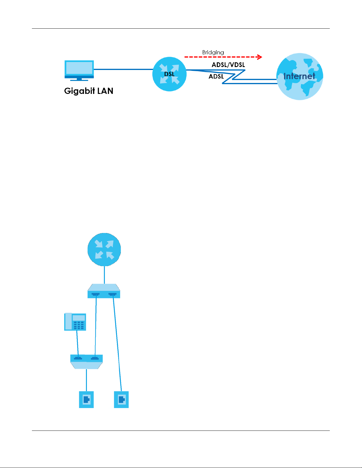
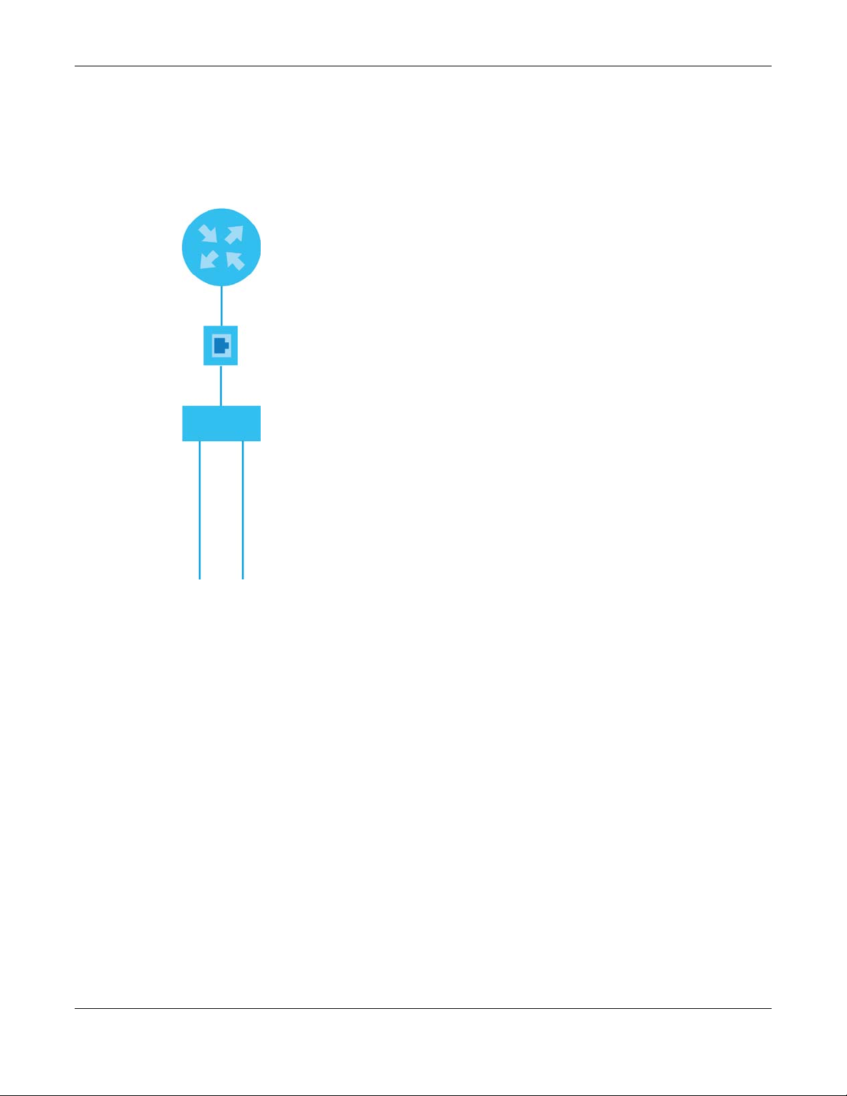
1.2.1 Internet Access
Your VMG provides shared Internet access by connecting the DSL port to the DSL or MODEM jack on a
splitter or your telephone jack. You can have multiple WAN services over one ADSL or VDSL. The VMG
cannot work in ADSL and VDSL mode at the same time.
A computer, gateway, or router can connect to the VMG’s LAN port.
VMG4005-B50A/B60A User’s Guide
9
Page 10
Chapter 1 Introducing the VMG
Line
Line
DSL
Tel
DSL
DSL 1
DSL 2
Wall
Figure 1 VMG’s Internet Access Application
DSL Bonding
DSL bonding allows the VMG to aggregate two DSL lines into a virtual connection. The VMG will have
higher bandwidth and faster transmission speed at longer distances. Note that the two DSL lines must
come from the same ISP, and they both need to support DSL bonding. Also, only DSL 1 supports
telephone service.
To set up your network for DSL bonding:
Example 1
1 Connect a two-line splitter to the VMG (DSL in the figure).
2 Connect two DSL lines to the two-line splitter.
3 Connect the two DSL lines to two separate telephone jacks (Wall).
Figure 2 VMG’s Internet Access Application: DSL Bonding (Example 1)
VMG4005-B50A/B60A User’s Guide
10
Page 11
Chapter 1 Introducing the VMG
Line
Line
DSL
DSL 1
DSL 2
Wall
DSL
ISP (COE)
Example 2
Connect the DSL port on the VMG (DSL in the figure) to a telephone jack.
The ISP will split the DSL connection at their end for DSL 1 and DSL 2 bonding.
Figure 3 VMG’s Internet Access Application: DSL Bonding (Example 2)
1.3 Manage the VMG
Use the Web Configurator for management of the VMG using a (supported) web browser.
1.4 Good Habits for Managing the VMG
Do the following things regularly to make the VMG more secure and to manage the VMG more
effectively.
• Change the Web Configurator password. Use a password that is not easy to guess and that consists of
different types of characters, such as numbers and letters.
• Write down the password and put it in a safe place.
• Back up the configuration (and make sure you know how to restore it). Restoring an earlier working
configuration may be useful if the device becomes unstable or even crashes. If you forget your
password, you will have to reset the VMG to its factory default settings. If you backed up an earlier
configuration file, you would not have to totally re-configure the VMG. You could simply restore your
last configuration.
VMG4005-B50A/B60A User’s Guide
11
Page 12
1.5 Hardware
This section describes the front and rear panels for each model. Refer to the VMG’s Quick Start Guides
to see the product drawings and how to make the hardware connections.
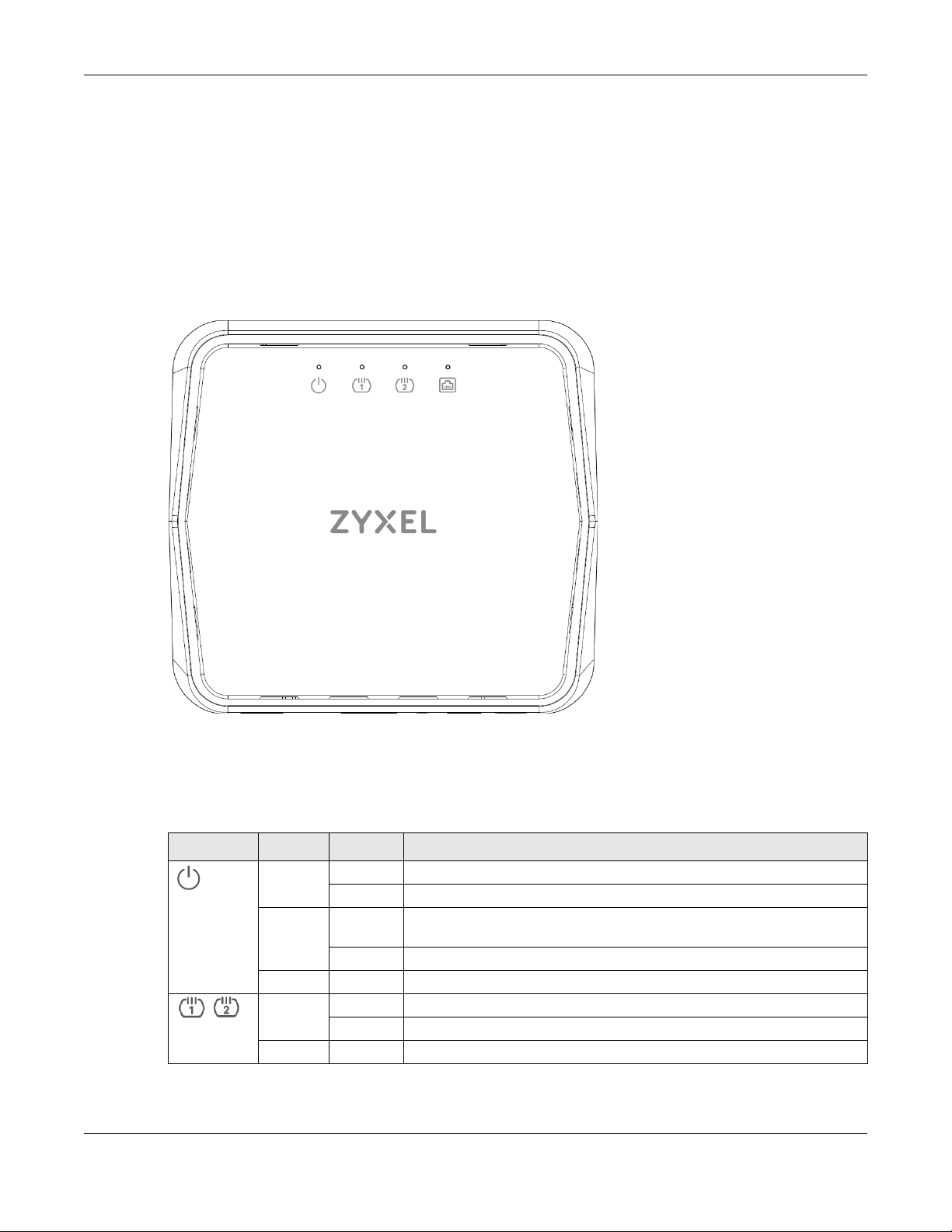
1.5.1 Front Panel
The LED indicators are located on the front panel.
Figure 4 Front Panel
Chapter 1 Introducing the VMG
1.5.2 LEDs (Lights)
None of the LEDs are on if the VMG is not receiving power.
Table 2 LED Descriptions
LED COLOR STATUS DESCRIPTION
Power
DSL1
DSL2
Green On The VMG is receiving power and ready for use.
Blinking The VMG is in the booting state and getting ready for use.
Red On The VMG detected an error while self-testing, or there is a device
malfunction.
Blinking The VMG is uploading firmware.
Off The VMG is not receiving power.
Green On The ADSL/VDSL line is up.
Blinking The VMG is initializing the ADSL/VDSL line.
Off The DSL line is down.
VMG4005-B50A/B60A User’s Guide
12
Page 13
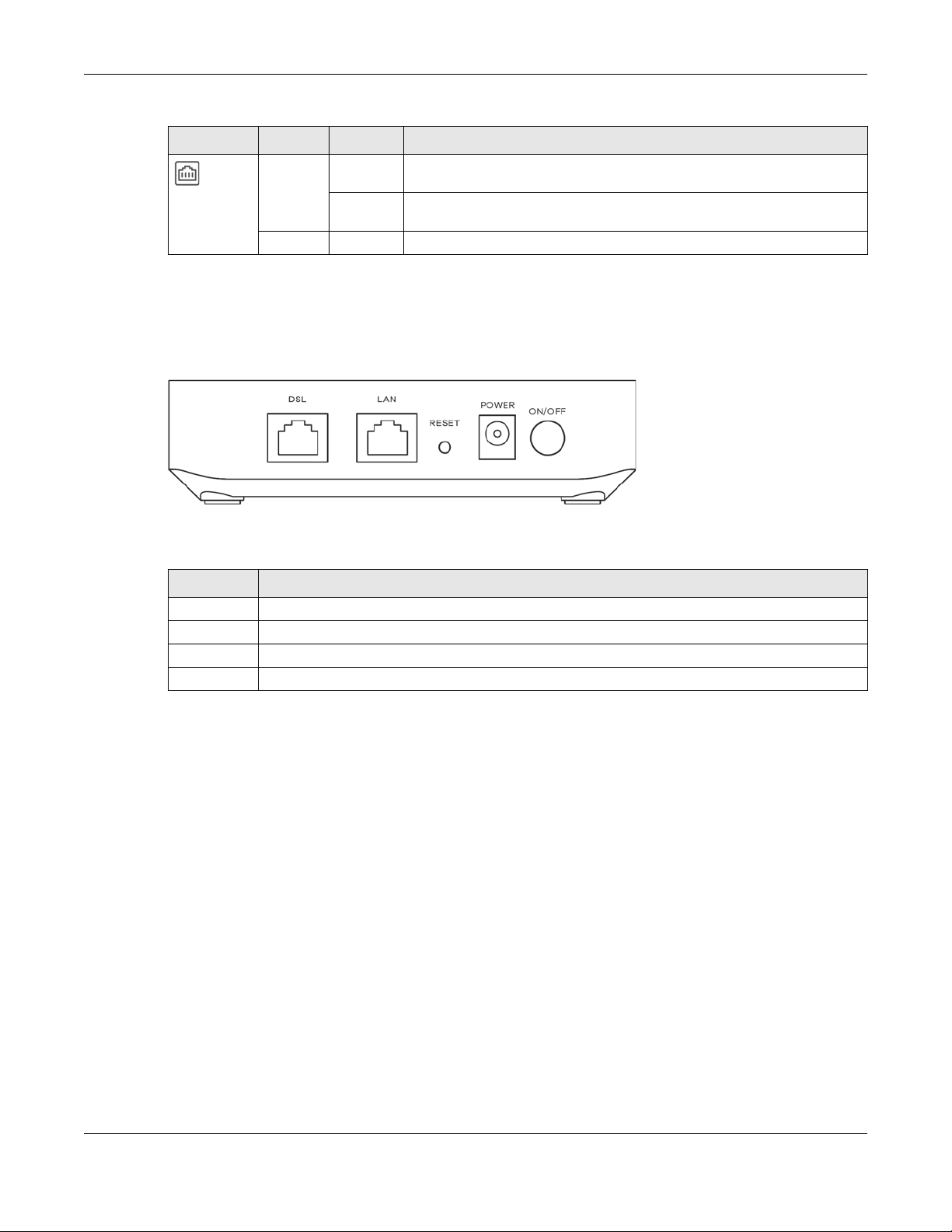
Table 2 LED Descriptions (continued)
LED COLOR STATUS DESCRIPTION
Green On The VMG has a successful 10/100/1000 Mbps Ethernet connection with a
Ethernet
1.5.3 Bottom Panel
The connection ports are located on the bottom panel.
Figure 5 Bottom Panel
Chapter 1 Introducing the VMG
device on the Local Area Network (LAN).
Blinking The VMG is sending or receiving data to/from the LAN at 10/100/1000
Mbps.
Off The VMG does not have an Ethernet connection with the LAN.
The following table describes the items on the bottom panel.
Rear Panel Ports
LABEL DESCRIPTION
DSL Connect a RJ-45 cable to the DSL port for Internet access.
LAN Connect a router/gateway to the Ethernet port for Internet access.
Reset Press the button to return the VMG to the factory defaults.
Power Connect the power adapter and then can press the power button to start the VMG.
1.5.4 RESET Button
If you forget your password or cannot access the Web Configurator, you will need to use the RESET
button to reload the factory-default configuration file. This means that you will lose all configurations
that you had previously. The password will be reset to the factory default (see the device label), and the
LAN IP address will be “192.168.1.1”.
1 Make sure the POWER LED is on (not blinking).
2 To set the device back to the factory default settings, press the RESET button for more than 5 seconds or
until the POWER LED begins to blink and then release it. When the POWER LED begins to blink, the defaults
have been restored and the device restarts.
VMG4005-B50A/B60A User’s Guide
13
Page 14
2.1 Overview
The Web Configurator is an HTML-based management interface that allows easy VMG setup and
management via Internet browser. Use Internet Explorer 11 and later versions or Mozilla Firefox 67.0.2 and
later versions or Safari 5.0 and later versions. The recommended screen resolution is 1024 by 768 pixels.
In order to use the Web Configurator you need to allow:
CHAPTER 2
The Web Configurator
• Web browser pop-up windows from your
Windows 10.
• JavaScript (enabled by default).
• Java permissions (enabled by default).
VMG. Web pop-up blocking is enabled by default in
2.1.1 Accessing the Web Configurator
1 Make sure your VMG hardware is properly connected (refer to the Quick Start Guide).
2 Make sure your computer has an IP address in the same subnet as the VMG. Your computer should
have an IP address from 192.168.1.2 to 192.168.1.254. See Section 18.4 on page 69 for details.
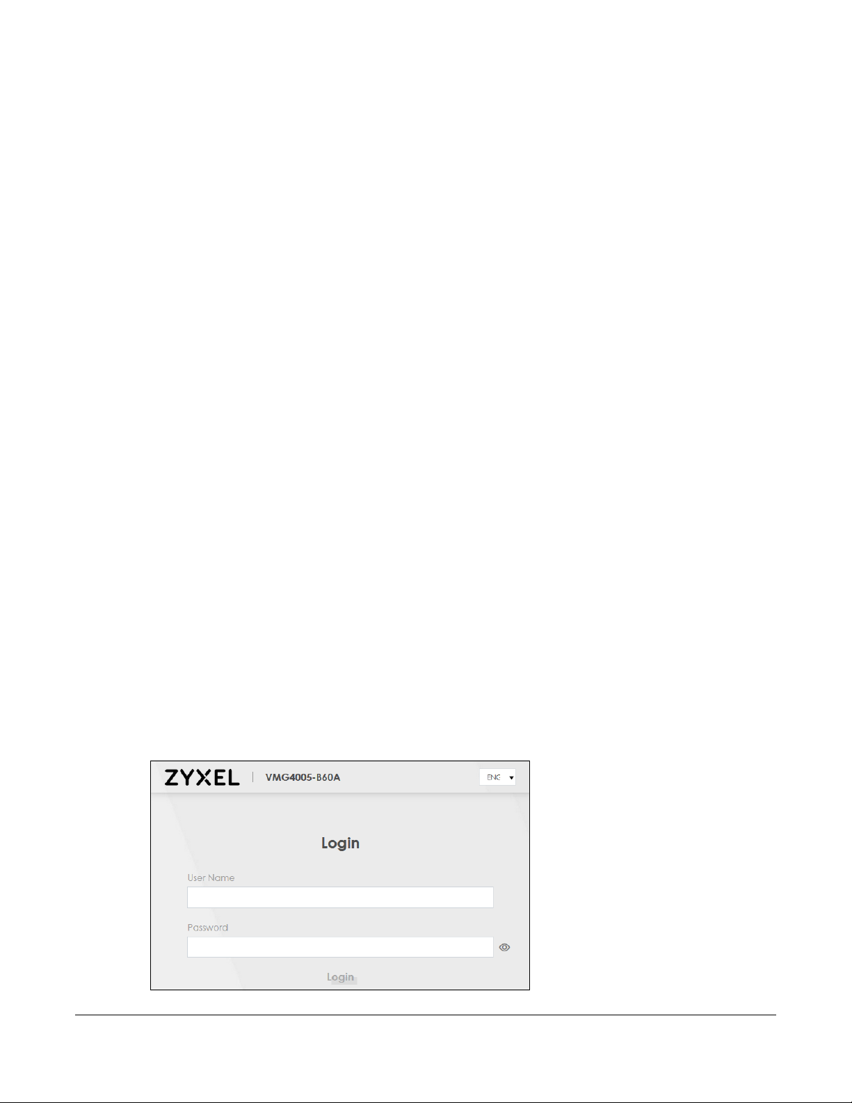
3 Launch your web browser. If the VMG does not automatically re-direct you to the login screen, go to
http://192.168.1.1.
4 A login screen displays. Select a language you prefer.
5 To access the administrative Web Configurator and manage the VMG, type the default username
admin and the randomly assigned default password (see the device label) in the login screen and click
Login. If you have changed the password, enter your password and click Login.
Figure 6 Login Screen
VMG4005-B50A/B60A User’s Guide
14
Page 15
Chapter 2 The Web Configurator
Note: The default allowable times that you can enter the Password is 3. If you entered the
wrong password for the fourth time, by default the Web Configurator will lock itself for 5
minutes before you can try entering the correct Password again. You can change
these settings in Maintenance > User Account > Add New / Edit Account (see Section
11.2.1 on page 40).
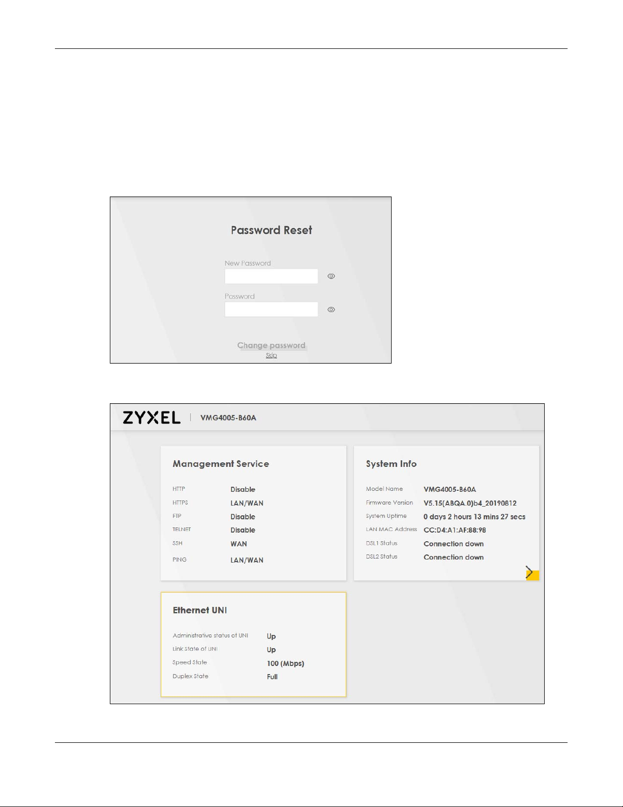
6 The following screen may display when you log into the Web Configurator for the first time. Enter a new
password, retype it to confirm, and click Change password. If you prefer to use the default password,
click Skip.
Figure 7 Change Password Screen
7 The Connection Status page appears. See Chapter 4 on page 23 for details.
Figure 8 Connection Status
VMG4005-B50A/B60A User’s Guide
15
Page 16
Chapter 2 The Web Configurator
A
B
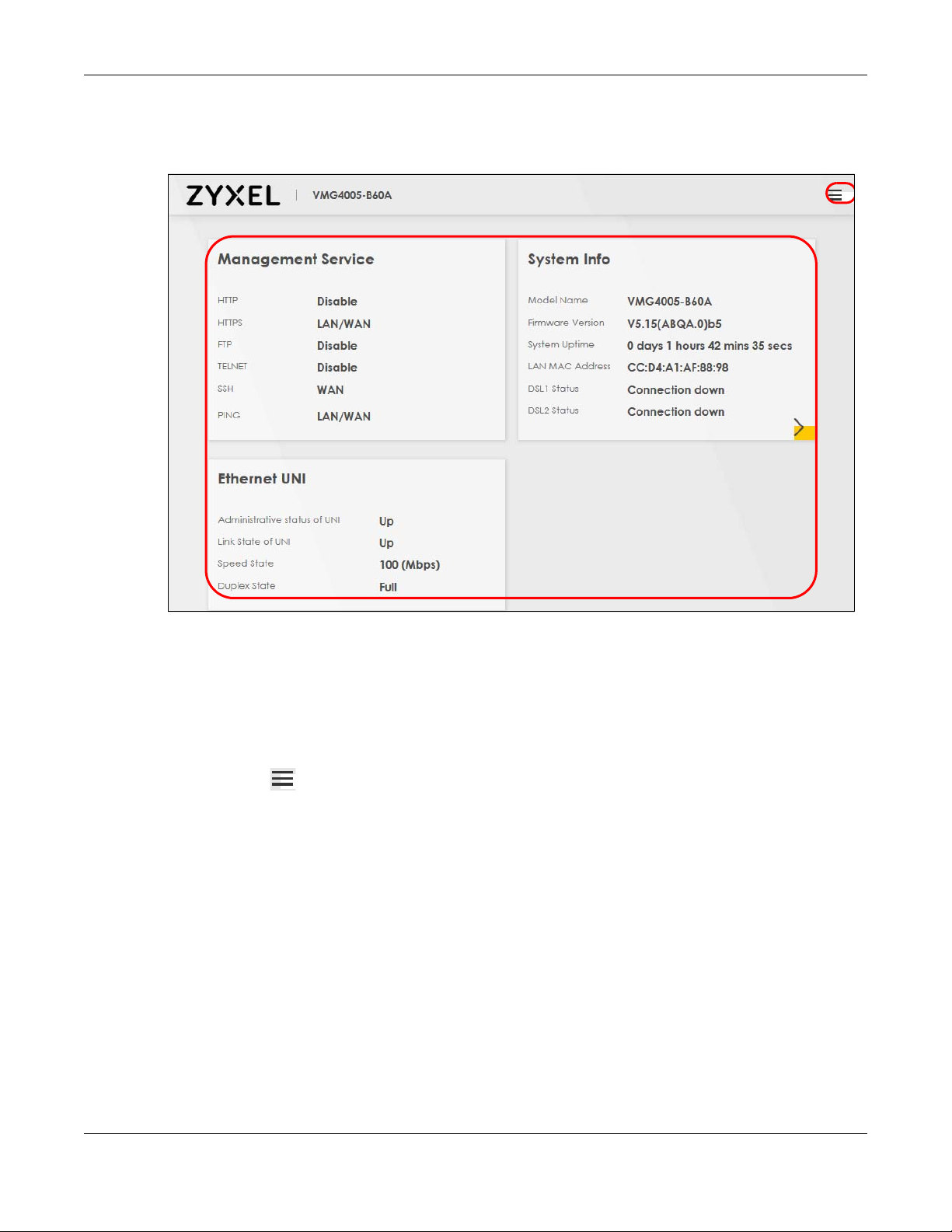
2.2 Web Configurator Layout
Figure 9 Screen Layout
As illustrated above, the main screen is divided into these parts:
• A - Menu Icon (Navigation Panel)
• B - Main Window
2.2.1 Menu Icon
Click this icon ( ) to display the navigation panel that contains configuration menus and quick links.
VMG4005-B50A/B60A User’s Guide
16
Page 17
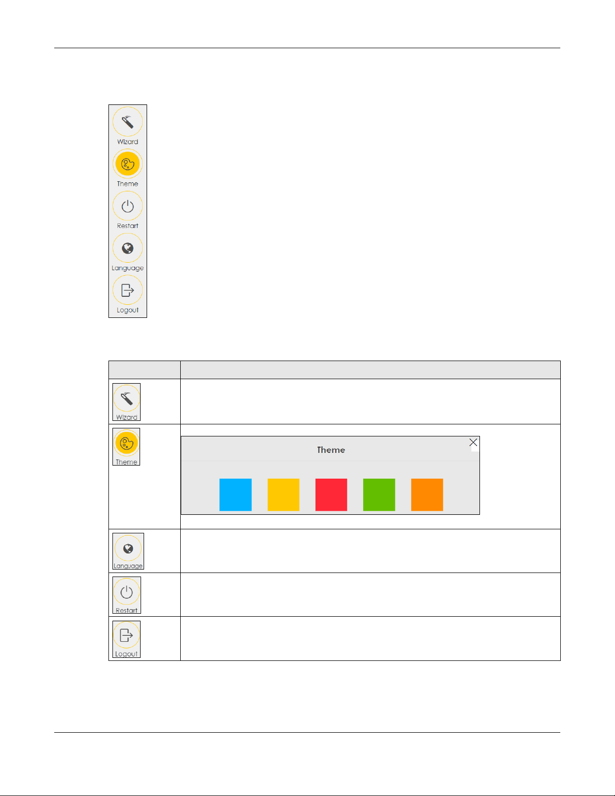
2.2.1.1 Quick Links
The quick links provides some icons on the right hand side.
Chapter 2 The Web Configurator
The icons provide the following functions.
Table 3 Quick Link Icons
ICON DESCRIPTION
Wizard: Click this icon to open screens where you can configure the VMG’s time zone Internet
access, and wireless settings. See Chapter 3 on page 19 for more information about the Wizard
screens.
Theme: Click this icon to select a color that you prefer and apply it to the Web Configurator.
Language: Select the language you prefer.
Restart: Click this icon to reboot the VMG without turning the power off.
Logout: Click this icon to log out of the Web Configurator.
2.2.1.2 Navigation Panel
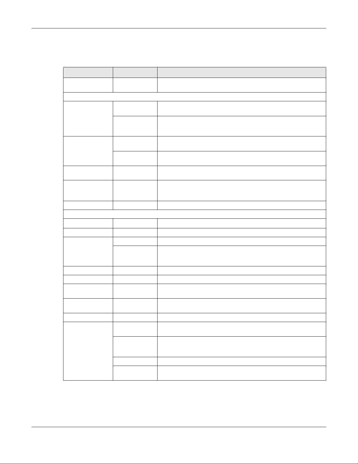
Use the menu items on the navigation panel to open screens to configure VMG features. The following
tables describe each menu item.
VMG4005-B50A/B60A User’s Guide
17
Page 18
Chapter 2 The Web Configurator
Note: The menu items on the navigation panel vary among the models. See Section 1.1 on
page 9 for more information about the feature differences of the VMG.
Table 4 Navigation Panel Summary
LINK TAB FUNCTION
Connection Status Use this screen to view the network status of the VMG and computers/
devices connected to it.
System Monitor
Log System Log Use this screen to view the status of events that occurred to the VMG.
Security Log Use this screen to view all security related events. You can select level
Traffic Status WAN Use this screen to view the status of all network traffic going through the
LAN Use this screen to view the status of all network traffic going through the
ARP Table ARP Table Use this screen to view the ARP table. It displays the IP and MAC address
MAC Address
Table
xDSL Statistics xDSL Statistics Use this screen to view the VMG’s xDSL traffic statistics.
Maintenance
System System
User Account User Account Use this screen to change user password on the VMG.
Remote
Management
Time Time Use this screen to change your VMG’s time and date.
Log Settings Log Setting Use this screen to change your VMG’s log settings.
Firmware
Upgrade
Backup/Restore Backup/Restore Use this screen to backup and restore your VMG’s configuration
Reboot Reboot Use this screen to reboot the VMG without turning the power off.
Diagnostic Ping&Traceroute
MAC Address
Table
MGMT Services Use this screen to enable specific traffic directions for network services.
Trust Domain Use this screen to view a list of public IP addresses which are allowed to
Firmware
Upgrade
&Nslookup
802.1ag Use this screen to configure CFM (Connectivity Fault Management) MD
802.3ah Use this screen to configure link OAM port parameters,
OAM Ping Use this screen to view information to help you identify problems with the
You can export or email the logs.
and category of the security events in their proper drop-down list
window.
WAN port of the VMG.
LAN ports of the VMG.
of each DHCP connection.
Use this screen to view the MAC address table. It displays the MAC
address of each client device and the VLAN group of each associated
wired client.
Use this screen to set VMG name and Domain name.
access the VMG through the services configured in the Maintenance >
Remote Management > MGMT Services screen.
Use this screen to upload firmware to your VMG.
(settings) or reset the factory default settings.
Use this screen to identify problems with the VMG. You can use Ping,
TraceRoute, or Nslookup to help you identify problems.
(maintenance domain) and MA (maintenance association), perform
connectivity tests and view test reports.
DSL connection.
VMG4005-B50A/B60A User’s Guide
18
Page 19
Quick Start Wizard
3.1 Overview
Use the Wizard screens to configure the VMG’s time zone and check Internet access.
3.2 Quick Start Wizard Setup
You can click the Wizard icon in the navigation panel to open the Wizard screens. See Section 2.2.1.1 on
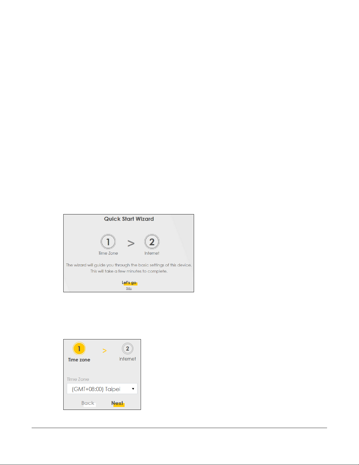
page 17 for more information about the navigation panel. After you click the Wizard icon, the following
screen appears. Click Let’s go to proceed with settings on time zone, basic Internet access, and wireless
networks. It will take you a few minutes to complete the settings on the Wizard screens. You can also
click Skip to leave the Wizard screens.
CHAPTER 3
Figure 10 Wizard - Home
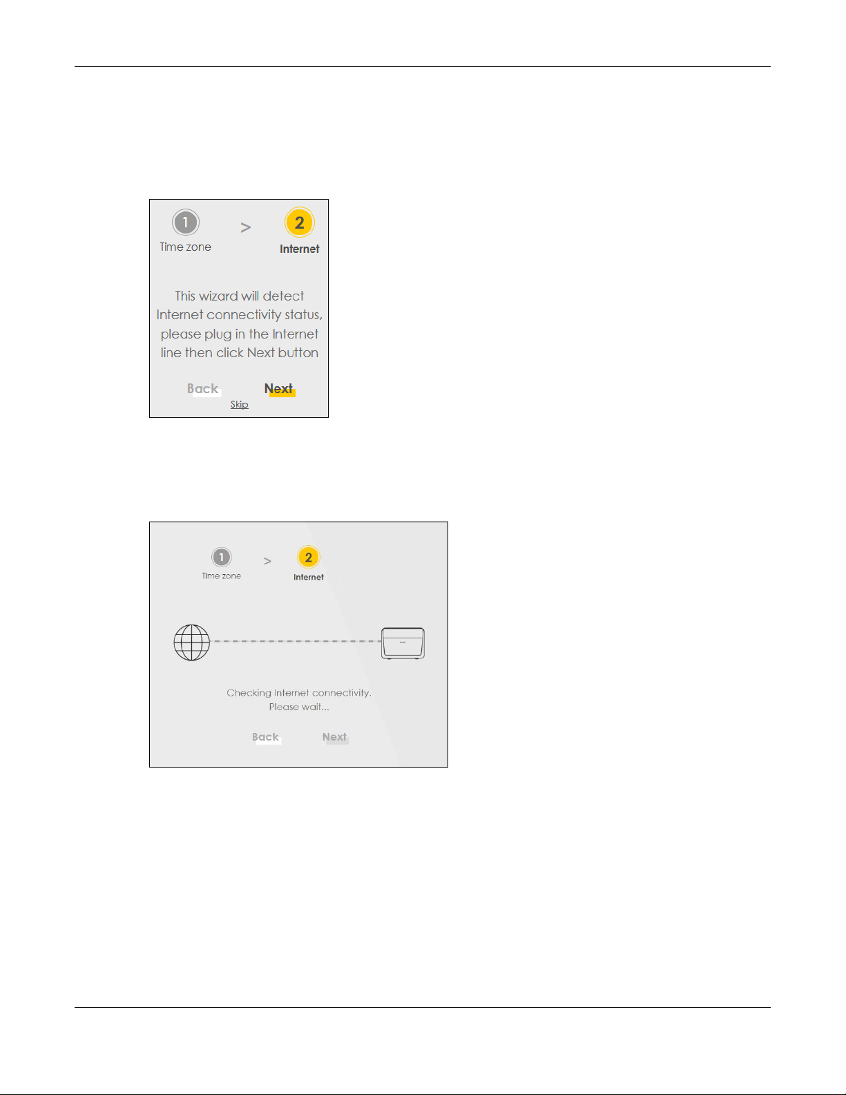
3.2.1 Time Zone
Select the time zone of your location. Click Next.
Figure 11 Wizard - Time Zone
VMG4005-B50A/B60A User’s Guide
19
Page 20
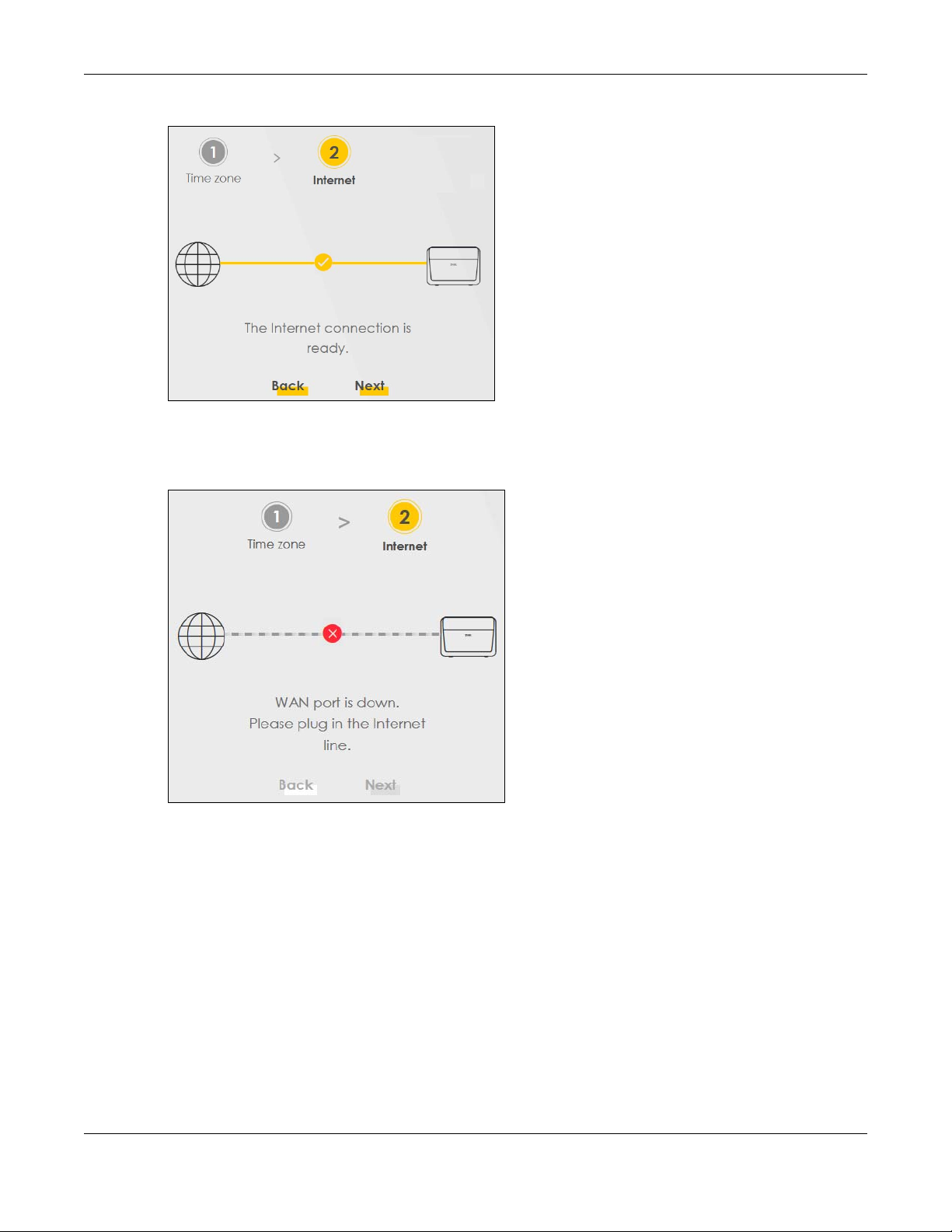
3.2.2 Internet
The VMG will check the Internet status automatically. Click Next to proceed. You can also click Skip to
pass checking of Internet connectivity in the Wizard.
Figure 12 Wizard - Internet
Internet Status
Chapter 3 Quick Start Wizard
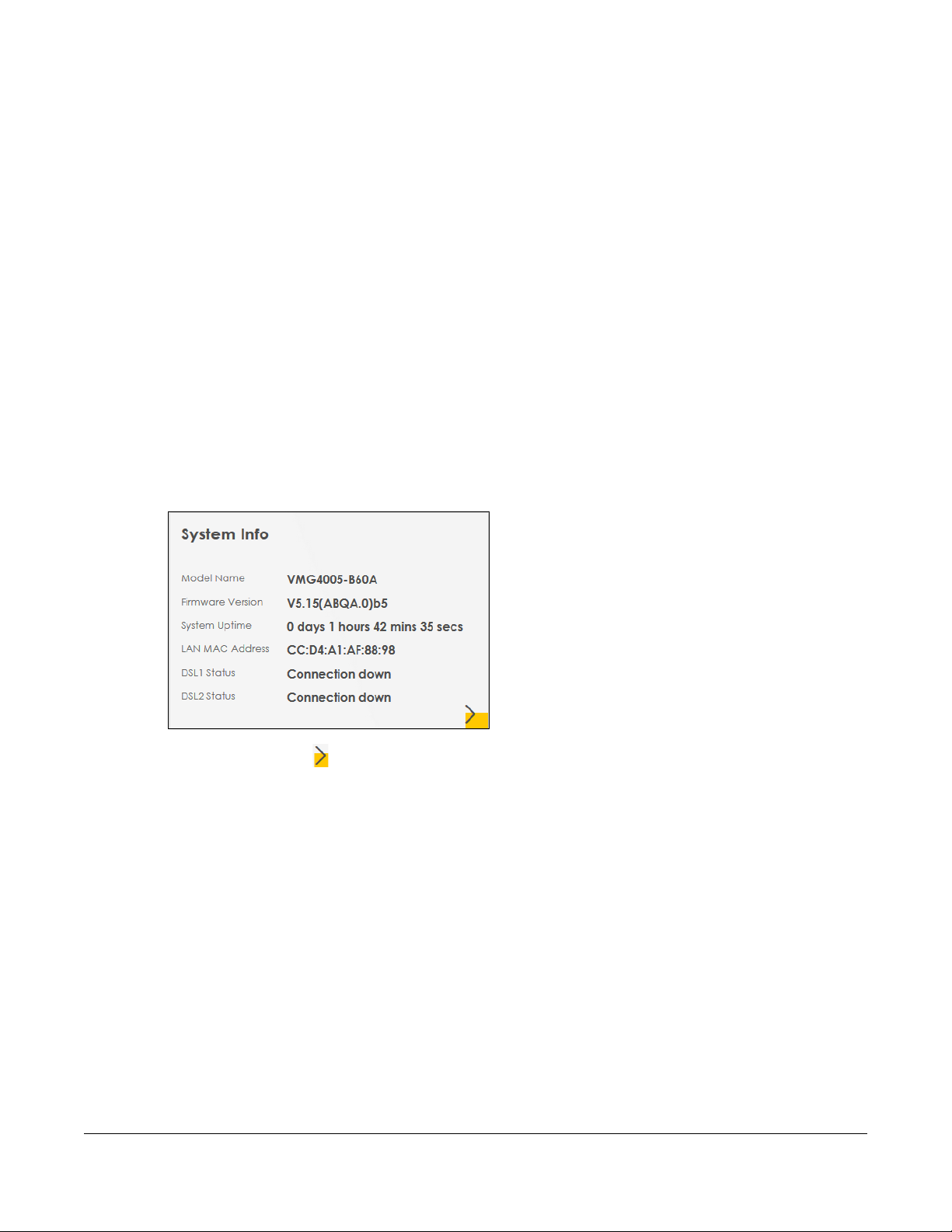
The VMG is checking the Internet status.
Figure 13 Wizard - Internet Check
Internet Connection
The VMG has Internet access. Click Next to return to the Status screen.
VMG4005-B50A/B60A User’s Guide
20
Page 21
Chapter 3 Quick Start Wizard
Figure 14 Wizard - Successful WAN Connection
If the VMG did not detect a WAN connection, connect a DSL cable for Internet access if you have not
connected any.
Figure 15 Wizard - WAN Connection is Down
VMG4005-B50A/B60A User’s Guide
21
Page 22

PART II
Technical Reference
22
Page 23
4.1 Status Overview
After you log into the Web Configurator, the Status screen appears. It shows the Management Service,
System Info, and Ethernet UNI of the VMG.
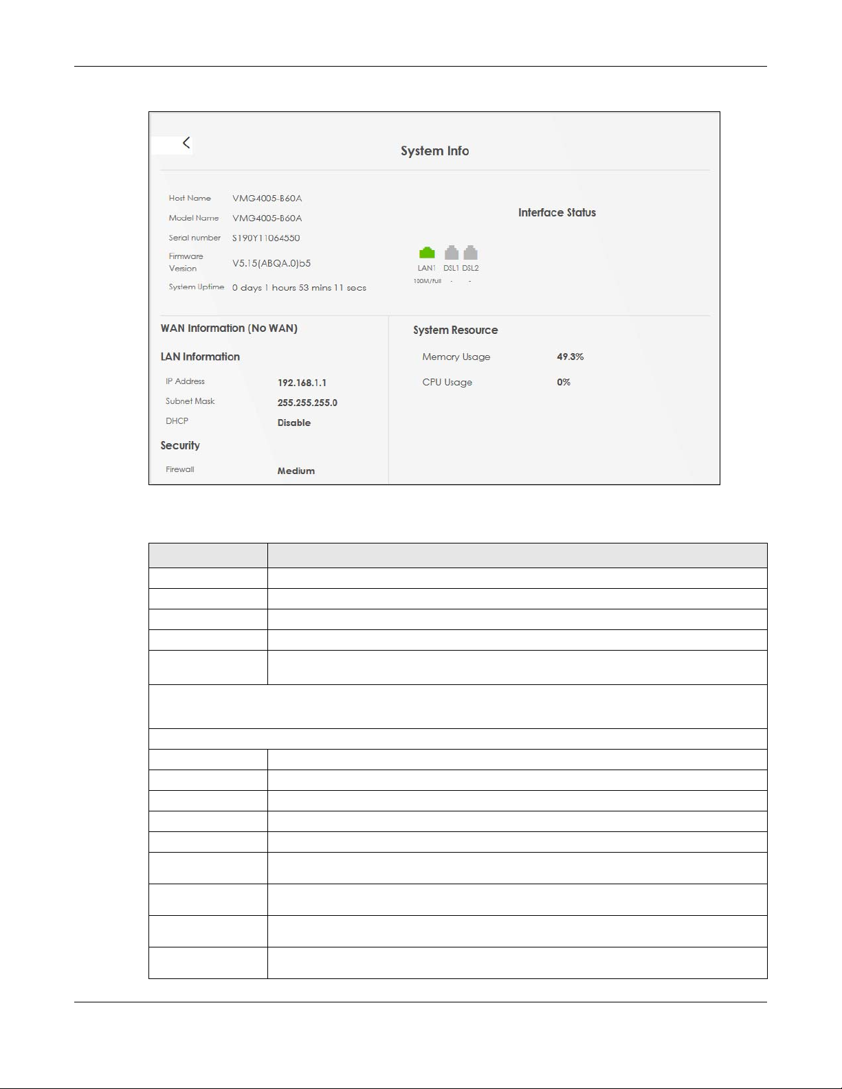
4.2 System Info
Use this screen to view the basic system information of the VMG.
Figure 16 System Info
CHAPTER 4
Status
Click the Arrow icon ( ) to open the following screen. Use this screen to view more system information,
WAN/LAN/Firewall information, interface status (LAN and DSL), and usage of system resource.
VMG4005-B50A/B60A User’s Guide
23
Page 24
Chapter 4 Status
Figure 17 System Info: Detailed Information
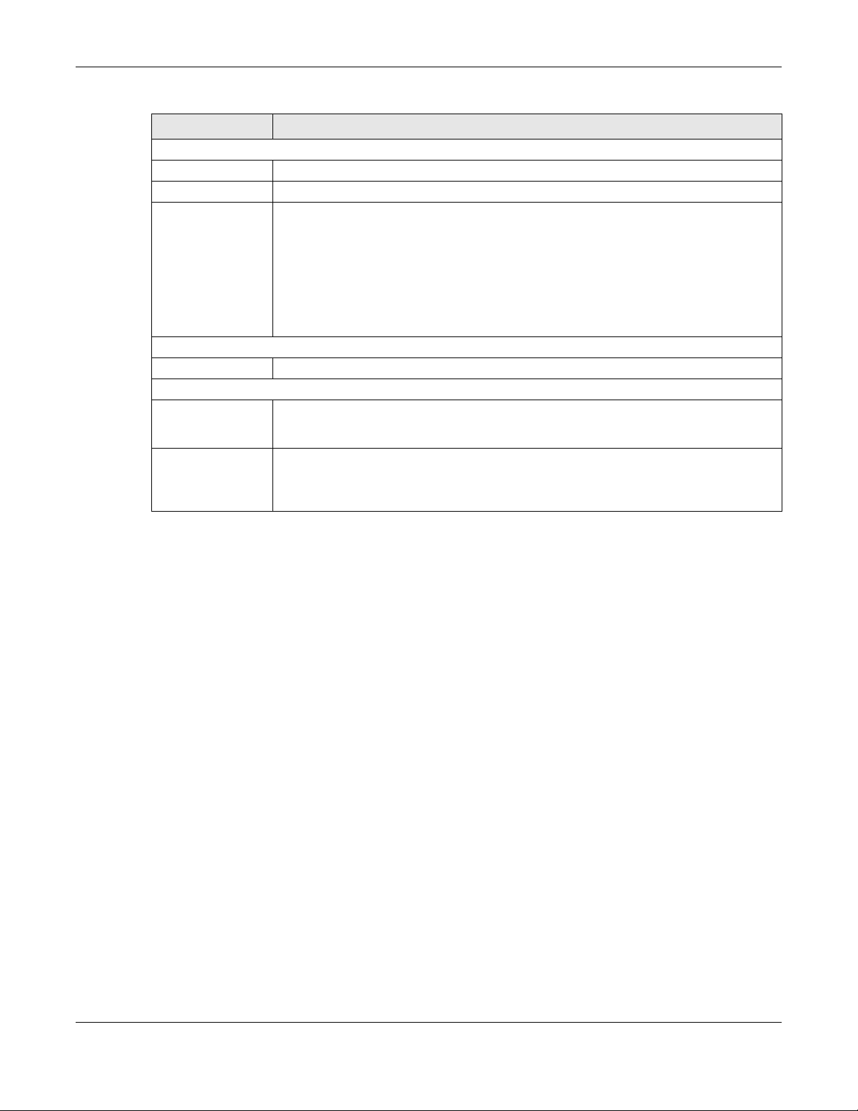
Each field is described in the following table.
Table 5 System Info: Detailed Information
LABEL DESCRIPTION
Host Name This field displays the VMG system name. It is used for identification.
Model Name This shows the model number of your VMG.
Serial Number This field displays the serial number of the VMG.
Firmware Version This is the current version of the firmware on the VMG.
System Up Time This field displays how long the VMG has been running since it last started up. The VMG starts
Interface Status
Virtual ports are shown here. You can see whether the ports are in use and their transmission rate.
WAN Information (These fields display when you have an Internet connection.)
Encapsulation This field displays the current encapsulation method.
IP Address This field displays the current IPv4 address of the VMG in the WAN.
IP Subnet Mask This field displays the current subnet mask in the WAN.
IPv6 Address This field displays the current IPv6 address of the VMG in the WAN.
MAC Address This shows the WAN Ethernet adapter MAC (Media Access Control) address of your VMG.
Primary DNS
server
Secondary DNS
server
Primary DNSv6
server
Secondary
DNSv6 server
up when you plug it in, when you restart it (Maintenance > Reboot), or when you reset it.
This field displays the first DNS server address assigned by the ISP.
This field displays the second DNS server address assigned by the ISP.
This field displays the first DNS server IPv6 address assigned by the ISP.
This field displays the second DNS server IPv6 address assigned by the ISP.
VMG4005-B50A/B60A User’s Guide
24
Page 25
Chapter 4 Status
Table 5 System Info: Detailed Information (continued)
LABEL DESCRIPTION
LAN Information (These fields display information about the LAN port.)
IP Address This is the current IPv4 address of the VMG.
Subnet Mask This is the current subnet mask.
DHCP This field displays what DHCP services the VMG is providing to the LAN. The possible values
are:
Server - The VMG is a DHCP server in the LAN. It assigns IP addresses to other computers in
the LAN.
Relay - The VMG acts as a surrogate DHCP server and relays DHCP requests and responses
between the remote server and the clients.
None - The VMG is not providing any DHCP services to the LAN.
Security
Firewall This displays the firewall’s current security level.
System Resource
Memory Usage This field displays what percentage of the VMG’s memory is currently used. Usually, this
percentage should not increase much. If memory usage does get close to 100%, the VMG is
probably becoming unstable, and you should restart the device.
CPU Usage This field displays what percentage of the VMG’s processing ability is currently used. When
this percentage is close to 100%, the VMG is running at full load, and the throughput is not
going to improve anymore. If you want some applications to have more throughput, you
should turn off other applications (for example, using QoS).
VMG4005-B50A/B60A User’s Guide
25
Page 26

5.1 Log Overview
These screens allow you to determine the categories of events that the VMG logs and then display
these logs or have the VMG send them to an administrator (through email) or to a syslog server.
5.1.1 What You Can Do in this Chapter
• Use the System Log screen to see the system logs (Section 5.2 on page 27).
• Use the Security Log screen to see the security-related logs for the categories that you select (Section
5.3 on page 27).
5.1.2 What You Need To Know
CHAPTER 5
Log
The following terms and concepts may help as you read this chapter.
Alerts and Logs
An alert is a type of log that warrants more serious attention. They include system errors, attacks (access
control) and attempted access to blocked web sites. Some categories such as System Errors consist of
both logs and alerts. You may differentiate them by their color in the View Log screen. Alerts display in
red and logs display in black.
Syslog Overview
The syslog protocol allows devices to send event notification messages across an IP network to syslog
servers that collect the event messages. A syslog-enabled device can generate a syslog message and
send it to a syslog server.
Syslog is defined in RFC 3164. The RFC defines the packet format, content and system log related
information of syslog messages. Each syslog message has a facility and severity level. The syslog facility
identifies a file in the syslog server. Refer to the documentation of your syslog program for details. The
following table describes the syslog severity levels.
Table 6 Syslog Severity Levels
CODE SEVERITY
0 Emergency: The system is unusable.
1 Alert: Action must be taken immediately.
2 Critical: The system condition is critical.
3 Error: There is an error condition on the system.
4 Warning: There is a warning condition on the system.
5 Notice: There is a normal but significant condition on the system.
VMG4005-B50A/B60A User’s Guide
26
Page 27

Table 6 Syslog Severity Levels
CODE SEVERITY
6 Informational: The syslog contains an informational message.
7 Debug: The message is intended for debug-level purposes.
5.2 System Log
Use the System Log screen to see the system logs. You can filter the entries by clicking on the Level and/
or Category drop-down list boxes. Click System Monitor > Log to open the System Log screen.
Figure 18 System Monitor > Log > System Log
Chapter 5 Log
The following table describes the fields in this screen.
Table 7 System Monitor > Log > System Log
LABEL DESCRIPTION
Level Select a severity level from the drop-down list box. This filters search results according to the
Category Select the type of logs to display.
Clear Log Click this to delete all the logs.
Refresh Click this to renew the log screen.
Export Log Click this to export the selected log(s).
# This field is a sequential value and is not associated with a specific entry.
Time This field displays the time the log was recorded.
Facility The log facility allows you to send logs to different files in the syslog server. Refer to the
Level This field displays the severity level of the log that the device is to send to this syslog server.
Category This field displays the type of the log.
Messages This field states the reason for the log.
severity level you have selected. When you select a severity, the VMG searches through all logs
of that severity or higher.
documentation of your syslog program for more details.
5.3 Security Log
Use the Security Log screen to see the security-related logs for the categories that you select. You can
filter the entries by clicking on the Level and/or Category drop-down list boxes. Click System Monitor >
Log > Security Log to open the following screen.
VMG4005-B50A/B60A User’s Guide
27
Page 28

Chapter 5 Log
Figure 19 System Monitor > Log > Security Log
The following table describes the fields in this screen.
Table 8 System Monitor > Log > Security Log
LABEL DESCRIPTION
Level Select a severity level from the drop-down list box. This filters search results according to the
severity level you have selected. When you select a severity, the VMG searches through all logs
of that severity or higher.
Category Select the type of logs to display.
Clear Log Click this to delete all the logs.
Refresh Click this to renew the log screen.
Export Log Click this to export the selected log(s).
# This field is a sequential value and is not associated with a specific entry.
Time This field displays the time the log was recorded.
Facility The log facility allows you to send logs to different files in the syslog server. Refer to the
documentation of your syslog program for more details.
Level This field displays the severity level of the log that the device is to send to this syslog server.
Category This field displays the type of the log.
Messages This field states the reason for the log.
VMG4005-B50A/B60A User’s Guide
28
Page 29

6.1 Traffic Status Overview
Use the Traffic Status screens to look at the network traffic status and statistics of the DSL and LAN
interfaces.
6.1.1 What You Can Do in this Chapter
• Use the WAN screen to view the DSL traffic statistics (Section 6.2 on page 29).
• Use the LAN screen to view the LAN traffic statistics (Section 6.3 on page 30).
6.2 WAN Status
CHAPTER 6
Traffic Status
Click System Monitor > Traffic Status to open the WAN screen. The figures in this screen show the number
of bytes received and sent through the VMG. Detailed information about each interface are listed in
the tables below.
Figure 20 System Monitor > Traffic Status > WAN
VMG4005-B50A/B60A User’s Guide
29
Page 30

Chapter 6 Traffic Status
The following table describes the fields in this screen.
Table 9 System Monitor > Traffic Status > WAN
LABEL DESCRIPTION
Refresh Interval Select how often you want the VMG to update this screen.
Connected
Interface
Packets Sent
Data This indicates the number of transmitted packets on this interface.
Error This indicates the number of frames with errors transmitted on this interface.
Drop This indicates the number of outgoing packets dropped on this interface.
Packets Received
Data This indicates the number of received packets on this interface.
Error This indicates the number of frames with errors received on this interface.
Drop This indicates the number of received packets dropped on this interface.
Disabled
Interface
Packets Sent
Data This indicates the number of transmitted packets on this interface.
Error This indicates the number of frames with errors transmitted on this interface.
Drop This indicates the number of outgoing packets dropped on this interface.
Packets Received
Data This indicates the number of received packets on this interface.
Error This indicates the number of frames with errors received on this interface.
Drop This indicates the number of received packets dropped on this interface.
This shows the name of the WAN interface that is currently connected.
This shows the name of the WAN interface that is currently disabled.
6.3 LAN Status
Click System Monitor > Traffic Status > LAN to open the following screen. The figures in this screen show
the number of bytes received and sent from each LAN port and wireless network.
VMG4005-B50A/B60A User’s Guide
30
Page 31

Chapter 6 Traffic Status
Figure 21 System Monitor > Traffic Status > LAN
The following table describes the fields in this screen.
Table 10 System Monitor > Traffic Status > LAN
LABEL DESCRIPTION
Refresh Interval Select how often you want the VMG to update this screen.
Interface This shows the LAN interface.
Bytes Sent This indicates the number of bytes transmitted on this interface.
Bytes Received This indicates the number of bytes received on this interface.
Interface This shows the LAN interface.
Sent (Packets)
Data This indicates the number of transmitted packets on this interface.
Error This indicates the number of frames with errors transmitted on this interface.
Drop This indicates the number of outgoing packets dropped on this interface.
Received (Packets)
Data This indicates the number of received packets on this interface.
Error This indicates the number of frames with errors received on this interface.
Drop This indicates the number of received packets dropped on this interface.
VMG4005-B50A/B60A User’s Guide
31
Page 32

7.1 ARP Table Overview
Address Resolution Protocol (ARP) is a protocol for mapping an Internet Protocol address (IP address) to
a physical machine address, also known as a Media Access Control or MAC address, on the local area
network.
An IP (version 4) address is 32 bits long. MAC addresses are 48 bits long. The ARP Table maintains an
association between each MAC address and its corresponding IP address.
7.1.1 How ARP Works
When an incoming packet destined for a host device on a local area network arrives at the device, the
device's ARP program looks in the ARP Table and, if it finds the address, sends it to the device.
CHAPTER 7
ARP Table
If no entry is found for the IP address, ARP broadcasts the request to all the devices on the LAN. The
device fills in its own MAC and IP address in the sender address fields, and puts the known IP address of
the target in the target IP address field. In addition, the device puts all ones in the target MAC field
(FF.FF.FF.FF.FF.FF is the Ethernet broadcast address). The replying device (which is either the IP address of
the device being sought or the router that knows the way) replaces the broadcast address with the
target's MAC address, swaps the sender and target pairs, and unicasts the answer directly back to the
requesting machine. ARP updates the ARP Table for future reference and then sends the packet to the
MAC address that replied.
VMG4005-B50A/B60A User’s Guide
32
Page 33

7.2 ARP Table Settings
Use the ARP table to view the IPv4-to-MAC address mapping(s) for the LAN. The neighbor table shows
the IPv6-to-MAC address mapping(s) of each neighbor. To open this screen, click System Monitor > ARP
Table.
Figure 22 System Monitor > ARP Table
Chapter 7 ARP Table
The following table describes the labels in this screen.
Table 11 System Monitor > ARP Table
LABEL DESCRIPTION
# This is the ARP table entry number.
IPv4/IPv6
Address
MAC Address This is the MAC address of the device with the listed IP address.
Device This is the type of interface used by the device. You can click on the device type to go to its
This is the learned IPv4 or IPv6 IP address of a device connected to a port.
configuration screen.
VMG4005-B50A/B60A User’s Guide
33
Page 34

Chapter 8 MAC Address Table
MAC Address Table
8.1 MAC Address Table Overview
The MAC address (media access control address) of a device is a unique identifier assigned to a
network interface controller for communications at the data link layer of a network segment. This table
lists the MAC address of each client device. VLAN information also shows when this device belongs to a
VLAN group.
Note: The MAC address of the VMG can be found in the System Info of the Status screen (see
Section 4.2 on page 23 for details).
CHAPTER 8
8.2 MAC Address Table Settings
Aside from the MAC address, the VLAN information of the associated wired clients are also listed in the
table. If the wired client does not tag with VLAN, the VLAN entry for this client is 0.
Click System Monitor > MAC Address Table to open the following screen.
Figure 23 System Monitor > MAC Address Table
The following table describes the labels in this screen.
Table 12 System Monitor > MAC Address Table
LABEL DESCRIPTION
# This is the MAC address table entry number.
VLAN This is the VLAN information of the associated wired clients. This displays 0 when the wired client
does not tag with VLAN.
MAC Address This is the MAC address of the wired client’s device.
Device This is the type of interface used by the wired client’s device.
VMG4005-B50A/B60A User’s Guide
34
Page 35

9.1 xDSL Statistics Overview
Use this screen to view detailed DSL information. It allows you to see the DSL status, check port details,
and see DSL counters. Click System Monitor > xDSL Statistics to open the following screen.
Figure 24 System Monitor > xDSL Statistics
CHAPTER 9
xDSL Statistics
The following table describes the labels in this screen.
Table 13 System > xDSL Statistics
LABEL DESCRIPTION
Monitor
Type Select Stats to display the various DSL status, downstream/upstream counters and port details in
the Status window. Select Profile to display the DSL PHY and driver version, modulations, VDSL
profiles, capability and PHY type configuration details in the Status window.
Refresh Interval Select the time interval for refreshing statistics.
Line Select which DSL line’s statistics you want to display.
Status
VMG4005-B50A/B60A User’s Guide
35
Page 36

Chapter 9 xDSL Statistics
Table 13 System > xDSL Statistics (continued)
LABEL DESCRIPTION
xDSL Training
Status
Mode This displays the ITU standard used for this connection.
Traffic Type This displays the type of traffic the DSL port is sending and receiving. Inactive displays if the DSL
Link Uptime This displays how long the port has been running (or connected) since the last time it was
xDSL Port Details
Upstream These are the statistics for the traffic direction going out from the port to the service provider.
Downstream These are the statistics for the traffic direction coming into the port from the service provider.
Line Rate These are the data transfer rates at which the port is sending and receiving data.
Actual Net Data
Rate
Trellis Coding This displays whether or not the port is using Trellis coding for traffic it is sending and receiving.
SNR Margin This is the upstream and downstream Signal-to-Noise Ratio margin (in dB). A DMT sub-carrier’s
Actual Delay This is the upstream and downstream interleave delay. It is the wait (in milliseconds) that
Transmit Power This is the upstream and downstream far end actual aggregate transmit power (in dBm).
This displays the current state of setting up the DSL connection.
port is not currently sending or receiving traffic.
started.
These are the rates at which the port is sending and receiving the payload data without
transport layer protocol headers and traffic.
Trellis coding helps to reduce the noise in ADSL transmissions. Trellis may reduce throughput but
it makes the connection more stable.
SNR is the ratio between the received signal power and the received noise power. The signalto-noise ratio margin is the maximum that the received noise power could increase with the
system still being able to meet its transmission targets.
determines the size of a single block of data to be interleaved (assembled) and then
transmitted. Interleave delay is used when transmission error correction (Reed- Solomon) is
necessary due to a less than ideal telephone line. The bigger the delay, the bigger the data
block size, allowing better error correction to be performed.
Upstream is how much power the port is using to transmit to the service provider. Downstream is
how much port the service provider is using to transmit to the port.
Receive Power Upstream is how much power the service provider is receiving from the port. Downstream is
how much power the port is receiving from the service provider.
Actual INP Sudden spikes in the line’s level of external noise (impulse noise) can cause errors and result in
lost packets. This could especially impact the quality of multimedia traffic such as voice or
video. Impulse noise protection (INP) provides a buffer to allow for correction of errors caused
by error correction to deal with this. The number of DMT (Discrete Multi-Tone) symbols shows the
level of impulse noise protection for the upstream and downstream traffic. A higher symbol
value provides higher error correction capability, but it causes overhead and higher delay
which may increase error rates in received multimedia data.
Attainable Net
Data Rate
xDSL Counters
Downstream These are the statistics for the traffic direction coming into the port from the service provider.
Upstream These are the statistics for the traffic direction going out from the port to the service provider.
FEC This is the number of Far End Corrected blocks.
CRC This is the number of Cyclic Redundancy Checks.
ES This is the number of Errored Seconds meaning the number of seconds containing at least one
SES This is the number of Severely Errored Seconds meaning the number of seconds containing 30%
UAS This is the number of UnAvailable Seconds.
These are the highest theoretically possible transfer rates at which the port could send and
receive payload data without transport layer protocol headers and traffic.
errored block or at least one defect.
or more errored blocks or at least one defect. This is a subset of ES.
VMG4005-B50A/B60A User’s Guide
36
Page 37

Chapter 9 xDSL Statistics
Table 13 System > xDSL Statistics (continued)
LABEL DESCRIPTION
LOS This is the number of Loss Of Signal seconds.
LOF This is the number of Loss Of Frame seconds.
LOM This is the number of Loss of Margin seconds.
Retr. This is the number of DSL retraining count in the BRCM DSL driver.
HostInitRetr This is the number of the retraining counts the host initiated.
FastRetr This is the number of DSL fast retraining counts.
FailedRetr This is the number of failed retraining attempts.
FailedFastRetr This is the number of failed fast retraining attempts.
VMG4005-B50A/B60A User’s Guide
37
Page 38

10.1 System Overview
In the System screen, you can name your VMG (Host) and give it an associated domain name. Domain
is the name given to a network. It will be required to reach a network from an external point (like the
Internet). Knowing the domain name will allow you to reach a particular network, and knowing the host
name will allow you to reach a particular device. For this reason, accessing a device from another
device within a network may work with just the host name (without the use of the domain name).
10.2 System Settings
Click Maintenance > System to open the following screen. Assign a unique name to this device so it can
be easily recognized on your network. You can use up to 30 characters, including spaces.
Figure 25 Maintenance > System
CHAPTER 10
System
The following table describes the labels in this screen.
Table 14 Maintenance > System
LABEL DESCRIPTION
Host Name Type a host name for your VMG. Enter a descriptive name of up to 16 alphanumeric characters,
Domain Name Type a Domain name for your host VMG.
Cancel Click Cancel to abandon this screen without saving.
Apply Click Apply to save your changes.
not including spaces, underscores, and dashes.
VMG4005-B50A/B60A User’s Guide
38
Page 39

Chapter 11 User Account
11.1 User Account Overview
In the User Account screen, you can view and modify the settings of the “admin” and other user
accounts that you use to log into the VMG to manage it.
11.2 User Account Settings
Click Maintenance > User Account to open the following screen. Use this screen to create or manage
user accounts and their privileges on the VMG.
CHAPTER 11
User Account
Figure 26 Maintenance > User Account
The following table describes the labels in this screen.
Table 15 Maintenance > User Account
LABEL DESCRIPTION
Add New
Account
# This is the index number.
Active This field indicates whether the user account is active or not.
User Name This field displays the name of the account used to log into the VMG Web Configurator.
Retry Times This field displays the number of times consecutive wrong passwords can be entered for this
Click this button to add a new user account.
Clear the check box to disable the user account. Select the check box to enable it.
account. 0 means there is no limit.
VMG4005-B50A/B60A User’s Guide
39
Page 40

Table 15 Maintenance > User Account (continued)
LABEL DESCRIPTION
Idle Timeout This field displays the length of inactive time before the VMG will automatically log the user out
of the Web Configurator.
Lock Period This field displays the length of time a user must wait before attempting to log in again after a
number if consecutive wrong passwords have been entered as defined in Retry Times.
Group This field displays whether this user has Administrator or User privileges.
Modify Click the Edit icon to configure the entry.
Click the Delete icon to remove the entry.
Cancel Click Cancel to restore your previously saved settings.
Apply Click Apply to save your changes.
11.2.1 User Account Add/Edit
Click Add New Account or the Edit icon of an existing account in the Maintenance > User Account to
open the following screen.
Figure 27 Maintenance > User Account > Add/Edit
Chapter 11 User Account
Note: When adding accounts, an Administrator can create new User or Administrator
accounts, while a User can only create User accounts
VMG4005-B50A/B60A User’s Guide
40
Page 41

Chapter 11 User Account
The following table describes the labels in this screen.
Table 16 Maintenance > User Account > Add/Edit
LABEL DESCRIPTION
Active Select Enable or Disable to activate or deactivate the user account.
User Name Enter a new name for the account. The User Name must contain 1 to 15 characters, including 0
Password Type your new system password. The Password must contain 6 to 64 characters, including 0 to 9
Verify New
Password
Retry Times Enter the number of times consecutive wrong passwords can be entered for this account. 0
Idle Timeout Enter the length of inactive time before the VMG will automatically log the user out of the web
Lock Period Enter the length of time a user must wait before attempting to log in again after a number if
Group Specify whether this user will have Administrator or User privileges. Administrator and User
Protocol Select the network protocol for operating network services over an unsecured network. Only
to 9, a to z, and !@#%*()-_+=~,.{}[]\. Spaces are not allowed.
and a to z. Note that as you type a password, the screen displays a (*) for each character you
type. After you change the password, use the new password to access the VMG.
Type the new password again for confirmation.
means there is no limit.
configurator.
consecutive wrong passwords have been entered as defined in Retry Times.
privileges are mostly the same, but the System settings will only display when you log in as an
Administrator.
HTTP&HTTPS is available when User is selected in the Group field.
Note: To use the Protocol Control feature for each user account under Remote
Management > MGMT Services, please enable the specified service.
Cancel Click Cancel to restore your previously saved settings.
OK Click OK to save your changes.
VMG4005-B50A/B60A User’s Guide
41
Page 42

CHAPTER 12
Remote Management
12.1 Remote Management Overview
Use remote management to control what services you can use through which interface(s) in order to
manage the VMG.
12.1.1 What You Can Do in this Chapter
• Use the MGMT Services screen to allow various approaches to access the VMG remotely from a DSL
and/or LAN connection (Section 12.2 on page 42).
• Use the Trust Domain screen to enable users to permit access from local management services by
entering specific IP addresses (Section 12.3 on page 43).
Note: The VMG is managed using the Web Configurator.
12.2 MGMT Services
Use this screen to configure through which interface(s), each service can access the VMG. You can also
specify service port numbers computers must use to connect to the VMG. Click Maintenance > Remote
Management > MGMT Services to open the following screen.
Figure 28 Maintenance > Remote Management > MGMT Services
VMG4005-B50A/B60A User’s Guide
42
Page 43

Chapter 12 Remote Management
The following table describes the fields in this screen.
Table 17 Maintenance > Remote Management > MGMT Services
LABEL DESCRIPTION
WAN Interface
used for services
Service This is the service you may use to access the VMG.
LAN Select the Enable check box for the corresponding services that you want to allow access to the
WAN Select the Enable check box for the corresponding services that you want to allow access to the
Trust Domain Select the Enable check box for the corresponding services that you want to allow access to the
Port You may change the server port number for a service if needed, however you must use the
Cancel Click Cancel to restore your previously saved settings.
Apply Click Apply to save your changes back to the VMG.
Select Any_WAN to have the VMG automatically activate the remote management service
when any WAN connection is up.
Select Multi_WAN and then select one or more WAN connections to have the VMG activate the
remote management service when the selected WAN connections are up.
• HTTP provides a non secured way.
• HTTPS is the secured version of HTTP, it makes sure that your data cannot be read during
transmission.
• FTP is the most common way of communication between two devices.
• TELNET provides a way to control your VMG remotely.
• SSH prevents leakage of data during remote management. Additionally, it can encrypt all
transmitted data.
• PING is a diagnostic tool that can check if your VMG is connected to the Internet.
VMG from the LAN.
VMG from all WAN connections.
VMG from the trusted hosts configured in the Maintenance > Remote MGMT > Trust Domain
screen.
If you only want certain WAN connections to have access to the VMG using the corresponding
services, then clear WAN, select Trust Domain and configure the allowed IP address(es) in the
Trust Domain screen.
same port number in order to use that service for remote management.
12.3 Trust Domain
Use this screen to view a list of public IP addresses which are allowed to access the VMG through the
services configured in the Maintenance > Remote Management > MGMT Services screen.
Click Maintenance > Remote Management > Trust Domain to open the following screen.
Note: If this list is empty, all public IP addresses cannot access the VMG from the WAN through
the specified services.
VMG4005-B50A/B60A User’s Guide
43
Page 44

Figure 29 Maintenance > Remote Management > Trust Domain
The following table describes the fields in this screen.
Table 18 Maintenance > Remote Management > Trust Domain
LABEL DESCRIPTION
Add Trust
Domain
IP Address This field shows a trusted host IP address.
Delete Click the Delete icon to remove the trust IP address.
Click this to add a trusted host IP address.
12.3.1 Add Trust Domain
Chapter 12 Remote Management
Use this screen to configure a public IP address which is allowed to access the VMG. Click the Add Trust
Domain button in the Maintenance > Remote Management > Trust Domain screen to open the following
screen.
Figure 30 Maintenance > Remote Management > Trust Domain > Add Trust Domain
The following table describes the fields in this screen.
Table 19 Maintenance > Remote Management > Trust Domain > Add Trust Domain
LABEL DESCRIPTION
IP Address Enter a public IPv4 IP address which is allowed to access the service on the VMG from the WAN.
OK Click OK to save your changes back to the VMG.
Cancel Click Cancel to restore your previously saved settings.
VMG4005-B50A/B60A User’s Guide
44
Page 45

13.1 Time Settings Overview
This chapter shows you how to configure system related settings, such as system time, password, name,
the domain name and the inactivity timeout interval.
13.2 Time Setup
To change your VMG’s time and date, click Maintenance > Time. The screen appears as shown. Use this
screen to configure the VMG’s time based on your local time zone. You can add a time server address,
select your time zone, and configure Daylight Savings if your location uses it.
CHAPTER 13
Time Settings
VMG4005-B50A/B60A User’s Guide
45
Page 46

Figure 31 Maintenance > Time
Chapter 13 Time Settings
VMG4005-B50A/B60A User’s Guide
46
Page 47

Chapter 13 Time Settings
The following table describes the fields in this screen.
Table 20 Maintenance > Time
LABEL DESCRIPTION
Current Date/Time
Current Time This field displays the time of your VMG.
Each time you reload this page, the VMG synchronizes the time with the time server.
Current Date This field displays the date of your VMG.
Each time you reload this page, the VMG synchronizes the date with the time server.
Time and Date Setup
First ~ Fifth Time
Server Address
Time Zone
Time zone Choose the time zone of your location. This will set the time difference between your time
Daylight Savings Daylight Saving Time is a period from late spring to early fall when many countries set their
Active Click this switch to enable or disable Daylight Saving Time. When the switch goes to the right
Start Rule Configure the day and time when Daylight Saving Time starts if you enabled Daylight Saving.
End Rule Configure the day and time when Daylight Saving Time ends if you enabled Daylight Saving.
Select an NTP time server from the drop-down list box.
Otherwise, select Other and enter the IP address or URL (up to 29 extended ASCII characters
in length) of your time server.
Select None if you don’t want to configure the time server.
Check with your ISP/network administrator if you are unsure of this information.
zone and Greenwich Mean Time (GMT).
clocks ahead of normal local time by one hour to give more daytime light in the evening.
, the function is enabled. Otherwise, it is not.
You can select a specific date in a particular month or a specific day of a specific week in a
particular month. The Time field uses the 24 hour format. Here are a couple of examples:
Daylight Saving Time starts in most parts of the United States on the second Sunday of March.
Each time zone in the United States starts using Daylight Saving Time at 2 A.M. local time. So in
the United States, set the day to Second, Sunday, the month to March and the time to 2 in the
Hour field.
Daylight Saving Time starts in the European Union on the last Sunday of March. All of the time
zones in the European Union start using Daylight Saving Time at the same moment (1 A.M.
GMT or UTC). So in the European Union you would set the day to Last, Sunday and the month
to March. The time you select in the o'clock field depends on your time zone. In Germany for
instance, you would select 2 in the Hour field because Germany's time zone is one hour
ahead of GMT or UTC (GMT+1).
You can select a specific date in a particular month or a specific day of a specific week in a
particular month. The Time field uses the 24 hour format. Here are a couple of examples:
Daylight Saving Time ends in the United States on the first Sunday of November. Each time
zone in the United States stops using Daylight Saving Time at 2 A.M. local time. So in the United
States you would set the day to First, Sunday, the month to November and the time to 2 in the
Hour field.
Daylight Saving Time ends in the European Union on the last Sunday of October. All of the
time zones in the European Union stop using Daylight Saving Time at the same moment (1
A.M. GMT or UTC). So in the European Union you would set the day to Last, Sunday, and the
month to October. The time you select in the o'clock field depends on your time zone. In
Germany for instance, you would select 2 in the Hour field because Germany's time zone is
one hour ahead of GMT or UTC (GMT+1).
Cancel Click Cancel to exit this screen without saving.
Apply Click Apply to save your changes.
VMG4005-B50A/B60A User’s Guide
47
Page 48

14.1 Logs Setting Overview
You can configure where the VMG sends logs and which logs and/or immediate alerts the VMG records
in the Logs Setting screen.
14.2 Log Setup
To change your VMG’s log settings, click Maintenance > Log Setting. The screen appears as shown.
If you have a LAN client on your network or a remote server that is running a syslog utility, you can also
save its log files by enabling Syslog Logging, selecting Remote or Local File and Remote in the Mode
field, and entering the IP address of the LAN client in the Syslog Server field. Remote allows you to store
logs on a syslog server, while Local File allows you to store them on the VMG. Local File and Remote
means your logs are stored both on the VMG and on a syslog server.
CHAPTER 14
Log Setting
VMG4005-B50A/B60A User’s Guide
48
Page 49

Chapter 14 Log Setting
Figure 32 Maintenance > Log Setting
The following table describes the fields in this screen.
Table 21 Maintenance > Log Setting
LABEL DESCRIPTION
Syslog Setting
Syslog Logging The VMG sends a log to an external syslog server. Click this switch to enable or disable to enable
Mode Select the syslog destination from the drop-down list box.
syslog logging. When the switch goes to the right , the function is enabled. Otherwise, it is
not.
If you select Remote, the log(s) will be sent to a remote syslog server. If you select Local File, the
log(s) will be saved in a local file. If you want to send the log(s) to a remote syslog server and
save it in a local file, select Local File and Remote.
Note: When Remote Syslog is enabled, the recipient may receive personal
information of Individuals on its behalf. The types of personal information being
collected includes without limitation to the following: host name, host IP
address and MAC address.
Syslog Server Enter the server name or IP address of the syslog server that will log the selected categories of
logs.
UDP Port Enter the port number used by the syslog server.
Active Log
System Log Select the categories of system logs that you want to record.
VMG4005-B50A/B60A User’s Guide
49
Page 50

Chapter 14 Log Setting
Table 21 Maintenance > Log Setting (continued)
LABEL DESCRIPTION
Security Log Select the categories of security logs that you want to record.
Cancel Click Cancel to restore your previously saved settings.
Apply Click Apply to save your changes.
VMG4005-B50A/B60A User’s Guide
50
Page 51

Firmware Upgrade
15.1 Firmware Upgrade Overview
This screen lets you upload new firmware to your VMG. You can download new firmware releases from
your nearest Zyxel FTP site (or www.zyxel.com) to upgrade your device’s performance.
Only use firmware for your device’s specific model. Refer to the label on
the bottom of your VMG.
15.2 Firmware Settings
Click Maintenance > Firmware Upgrade to open the following screen. Download the latest firmware file
from the Zyxel website and upload it to your VMG using this screen. The upload process uses HTTP
(Hypertext Transfer Protocol) and may take up to two minutes. After a successful upload, the VMG will
reboot.
CHAPTER 15
Do NOT turn off the VMG while firmware upload is in progress!
Figure 33 Maintenance > Firmware Upgrade
The following table describes the labels in this screen. After you see the firmware updating screen, wait
VMG4005-B50A/B60A User’s Guide
51
Page 52

Chapter 15 Firmware Upgrade
two minutes before logging into the VMG again.
Table 22 Maintenance > Firmware Upgrade
LABEL DESCRIPTION
Upgrade Firmware
Restore Default
Settings After
Firmware
Upgrade
Current
Firmware
Version
File Path Type in the location of the file you was not to upload in this field or click Browse to find it.
Browse Click this to find the .bin file you want to upload. Remember that you must decompress
Upload Click this to begin the upload process. This process may take up to two minutes.
Upgrade WWAN Package
Current
WWAN
Package
Version
File Path Type in the location of the file you want to upload in this field or click Browse to find it.
Browse Click this to find the .bin file you want to upload. Remember that you must decompress
Upload Click this to begin the upload process. This process may take up to two minutes.
Select the check box to have the VMG automatically reset itself after the new firmware is
uploaded.
This is the present Firmware version and the date created.
compressed (.zip) files before you can upload them.
This is the present WWAN Package version and the date created.
compressed (.zip) files before you can upload them.
Figure 34 Firmware Uploading
After two minutes, log in again and check your new firmware version in the Status screen.
If the upload was not successful, the following screen will appear. Click OK to go back to the Firmware
Upgrade screen.
VMG4005-B50A/B60A User’s Guide
52
Page 53

Chapter 15 Firmware Upgrade
Figure 35 Error Message
Note that the VMG automatically restarts during the upload, causing a temporary network disconnect.
In some operating systems, you may see the following icon on your desktop.
Network Temporarily Disconnected
VMG4005-B50A/B60A User’s Guide
53
Page 54

Backup/Restore
16.1 Backup/Restore Overview
The Backup/Restore screen allows you to backup and restore device configurations. You can also reset
your device settings back to the factory default.
16.2 Backup/Restore Settings
Click Maintenance > Backup/Restore. Information related to factory default settings and backup
configuration are shown in this screen. You can also use this to restore previous device configurations.
Figure 36 Maintenance > Backup/Restore
CHAPTER 16
Backup Configuration
Backup Configuration allows you to back up (save) the VMG’s current configuration to a file on your
computer. Once your VMG is configured and functioning properly, it is highly recommended that you
VMG4005-B50A/B60A User’s Guide
54
Page 55

Chapter 16 Backup/Restore
back up your configuration file before making configuration changes. The backup configuration file will
be useful in case you need to return to your previous settings.
Click Backup to save the VMG’s current configuration to your computer.
Restore Configuration
Restore Configuration allows you to upload a new or previously saved configuration file from your
computer to your VMG.
Table 23 Restore Configuration
LABEL DESCRIPTION
File Path Type in the location of the file you want to upload in this field or click Browse to find it.
Browse Click this to find the file you want to upload. Remember that you must decompress compressed
(.ZIP) files before you can upload them.
Upload Click this to begin the upload process.
Do NOT turn off the VMG while configuration file upload is in progress.
After the VMG configuration has been restored successfully, the login screen appears. Login again to
restart the VMG.
The VMG automatically restarts in this time causing a temporary network disconnect. In some operating
systems, you may see the following icon on your desktop.
Figure 37 Network Temporarily Disconnected
If you uploaded the default configuration file you may need to change the IP address of your computer
to be in the same subnet as that of the default device IP address (192.168.1.1).
If the upload was not successful, the following screen will appear. Click OK to go back to the
Configuration screen.
Figure 38 Configuration Upload Error
Reset to Factory Defaults
Click the Reset button to clear all user-entered configuration information and return the VMG to its
factory defaults. The following warning screen appears.
VMG4005-B50A/B60A User’s Guide
55
Page 56

Chapter 16 Backup/Restore
Figure 39 Reset Warning Message
Figure 40 Reset In Process Message
You can also press the RESET button on the bottom panel to reset the factory defaults of your VMG.
Refer to Section 1.5.4 on page 13 for more information on the RESET button.
16.3 Reboot
System Reboot allows you to reboot the VMG remotely without turning the power off. You may need to
do this if the VMG hangs, for example.
Click Maintenance > Reboot. Click Reboot to have the VMG reboot. This does not affect the VMG's
configuration.
VMG4005-B50A/B60A User’s Guide
56
Page 57

Chapter 16 Backup/Restore
Figure 41 Maintenance > Reboot
VMG4005-B50A/B60A User’s Guide
57
Page 58

Chapter 17 Diagnostic
17.1 Diagnostic Overview
The Diagnostic screens display information to help you identify problems with the VMG.
The route between a Central Office Very-high-bit-rate Digital Subscriber Line (CO VDSL) switch and one
of its Customer-Premises Equipment (CPE) may go through switches owned by independent
organizations. A connectivity fault point generally takes time to discover and impacts subscriber’s
network access. In order to eliminate the management and maintenance efforts, IEEE 802.1ag is a
Connectivity Fault Management (CFM) specification which allows network administrators to identify
and manage connection faults. Through discovery and verification of the path, CFM can detect,
analyze and isolate connectivity faults in bridged LANs.
CHAPTER 17
Diagnostic
17.1.1 What You Can Do in this Chapter
• The Ping & TraceRoute & NsLookup screen lets you ping an IP address or trace the route packets take
to a host (Section 17.3 on page 59).
• The 802.1ag screen lets you perform CFM actions (Section 17.4 on page 60).
• The 802.3ah screen lets you configure link OAM port parameters(Section 17.5 on page 61).
• The OAM Ping screen lets you send an ATM OAM (Operation, Administration and Maintenance)
packet to verify the connectivity of a specific PVC. (Section 17.6 on page 62).
17.2 What You Need to Know
The following terms and concepts may help as you read through this chapter.
How CFM Works
A Maintenance Association (MA) defines a VLAN and associated Maintenance End Point (MEP) ports
on the device under a Maintenance Domain (MD) level. An MEP port has the ability to send
Connectivity Check Messages (CCMs) and get other MEP ports information from neighbor devices’
CCMs within an MA.
CFM provides two tests to discover connectivity faults.
• Loopback test - checks if the MEP port receives its Loop Back Response (LBR) from its target after it
sends the Loop Back Message (LBM). If no response is received, there might be a connectivity fault
between them.
VMG4005-B50A/B60A User’s Guide
58
Page 59

Chapter 17 Diagnostic
• Link trace test - provides additional connectivity fault analysis to get more information on where the
fault is. If an MEP port does not respond to the source MEP, this may indicate a fault. Administrators
can take further action to check and resume services from the fault according to the line
connectivity status report.
17.3 Ping & TraceRoute & NsLookup
Use this screen use ping, traceroute, or nslookup for troubleshooting. Ping and traceroute are used to
test whether a particular host is reachable. After entering an IP address and clicking on one of the
buttons to start a test, the results will be shown in the Ping/Traceroute Test area. Use nslookup to find the
IP address for a host name and vice versa. Click Maintenance > Diagnostic >
Ping&TraceRoute&NsLookup to open the screen shown next.
Figure 42 Maintenance > Diagnostic > Ping&TraceRoute&NsLookup
The following table describes the fields in this screen.
Table 24 Maintenance > Diagnostic > Ping & TraceRoute & NsLookup
LABEL DESCRIPTION
URL or IP
Address
Ping Click this to ping the IPv4 address that you entered.
Ping 6 Click this to ping the IPv6 address that you entered.
Trace Route Click this to display the route path and transmission delays between the VMG to the IPv4
Trace Route 6 Click this to display the route path and transmission delays between the VMG to the IPv6
Nslookup Click this button to perform a DNS lookup on the IP address of a computer you enter.
Type the IP address of a computer that you want to perform ping, traceroute, or nslookup in
order to test a connection.
address that you entered.
address that you entered.
VMG4005-B50A/B60A User’s Guide
59
Page 60

17.4 802.1ag (CFM)
Click Maintenance > Diagnostic > 802.1ag to open the following screen. Use this screen to configure
and perform Connectivity Fault Management (CFM) actions as defined by the IEEE 802.1ag standard.
CFM protocols include Continuity Check Protocol (CCP), Link Trace (LT), and Loopback (LB).
Figure 43 Maintenance > Diagnostic > 802.1ag
Chapter 17 Diagnostic
The following table describes the fields in this screen.
Table 25 Maintenance > Diagnostic > 802.1ag
LABEL DESCRIPTION
802.1ag Connectivity Fault Management
IEEE 802.1ag
CFM
Y.1731 Click this switch to enable or disable Y.1731, which monitors Ethernet performance. When the
Interface Select the interface on which you want to enable the IEE 802.1ag CFM.
Maintenance
Domain (MD)
Level
Click this switch to enable or disable the IEEE802.1ag CFM specification, which allows network
administrators to identify and manage connection faults. When the switch goes to the right
, the function is enabled. Otherwise, it is not.
switch goes to the right , the function is enabled. Otherwise, it is not.
Select a level (0-7) under which you want to create an MA.
VMG4005-B50A/B60A User’s Guide
60
Page 61

Chapter 17 Diagnostic
Table 25 Maintenance > Diagnostic > 802.1ag (continued)
LABEL DESCRIPTION
MD Name Enter a descriptive name for the MD (Maintenance Domain).
MA ID Enter a descriptive name to identify the Maintenance Association.
MEG ID Enter a descriptive name to identify the Maintenance Entity Group. This field only appears if the
Y.1731 field is enabled.
802.1Q VLAN ID Type a VLAN ID (1-4094) for this MA.
Local MEP ID Enter the local Maintenance Endpoint Identifier (1~8191).
CCM Select Enable to continue sending MEP information by CCM (Connectivity Check Messages).
When CCMs are received the VMG will always process it, whether CCM is enabled or not.
Remote MEP ID Enter the remote Maintenance Endpoint Identifier (1~8191).
Test the connection to another Maintenance End Point (MEP)
Destination
MAC Address
Test Result
Loopback
Message (LBM)
Linktrace
Message (LTM)
Apply Click this button to save your changes.
Send Loopback Click this button to have the selected MEP send the LBM (Loop Back Message) to a specified
Send Linktrace Click this button to have the selected MEP send the LTMs (Link Trace Messages) to a specified
Enter the target device’s MAC address to which the VMG performs a CFM loopback and
linktrace test.
This shows Pass if a Loop Back Messages (LBMs) responses are received. If LBMs do not get a
response it shows Fail.
This shows the MAC address of MEPs that respond to the LTMs.
remote end point.
remote end point.
17.5 802.3ah (OAM)
Click Maintenance > Diagnostic > 803.ah to open the following screen. Link layer Ethernet OAM
(Operations, Administration and Maintenance) as described in IEEE 802.3ah is a link monitoring protocol.
It utilizes OAM Protocol Data Units (OAM PDU’s) to transmit link status information between directly
connected Ethernet devices. Both devices must support IEEE 802.3ah.
Figure 44 Maintenance > Diagnostic > 802.3ah
VMG4005-B50A/B60A User’s Guide
61
Page 62

Chapter 17 Diagnostic
The following table describes the labels in this screen.
Table 26 Maintenance > Diagnostics > 802.3ah
LABEL DESCRIPTION
IEEE 802.3ah Ethernet OAM Click this switch to enable or disable the Ethernet OAM on the specified interface.
Interface Select the interface on which you want to enable the IEEE802.3ah.
OAM ID Enter a positive integer to identify this node.
Auto Event Click this switch to detect link status and send a notification when an error (such as
Features Select Variable Retrieval so the VMG can respond to requests for information, such
When the switch goes to the right , the function is enabled. Otherwise, it is not.
errors in symbol, frames, or seconds) is detected. Otherwise, disable this and you will
not be notified. When the switch goes to the right , the function is enabled.
Otherwise, it is not.
as requests for Ethernet counters and statistics, about link events.
Select Link Events so the VMG can interpret link events, such as link fault and dying
asp.Link events are set in event notification PDUs (Protocol Data Units), and indicate
when the number of errors in a certain given interval (time, number of frames,
number of symbols, or number of errored frame seconds) exceeds a specified
threshold. Organizations may create organization-specific link event TLVs as well.
Select Remote Loopback so the VMG can accept loopback control PDUs to convert
VMG into loopback mode.
Apply Click this button to save your changes.
17.6 OAM Ping
Click Maintenance > Diagnostic > OAM Ping to open the screen shown next. Use this screen to perform
an OAM (Operation, Administration and Maintenance) F4 or F5 loopback test on a PVC. The VMG sends
an OAM F4 or F5 packet to the DSLAM or ATM switch and then returns it to the VMG. The test result then
displays in the text box. ATM sets up virtual circuits over which end systems communicate. The
terminology for virtual circuits is as follows:
• Virtual Channel (VC) Logical connections between ATM devices
• Virtual Path (VP) A bundle of virtual channels
• Virtual Circuits A series of virtual paths between circuit end points
Figure 45 Virtual Circuit Topology
Select Active Mode so the VMG initiates OAM discovery, send information PDUs; and
may send event notification PDUs, variable request/response PDUs, or loopback
control PDUs.
VMG4005-B50A/B60A User’s Guide
62
Page 63

Chapter 17 Diagnostic
Think of a virtual path as a cable that contains a bundle of wires. The cable connects two points and
wires within the cable provide individual circuits between the two points. In an ATM cell header, a VPI
(Virtual Path Identifier) identifies a link formed by a virtual path; a VCI (Virtual Channel Identifier)
identifies a channel within a virtual path. A series of virtual paths make up a virtual circuit.
F4 cells operate at the virtual path (VP) level, while F5 cells operate at the virtual channel (VC) level. F4
cells use the same VPI as the user data cells on VP connections, but use different predefined VCI values.
F5 cells use the same VPI and VCI as the user data cells on the VC connections, and are distinguished
from data cells by a predefined Payload Type Identifier (PTI) in the cell header. Both F4 flows and F5
flows are bidirectional and have two types.
• segment F4 flows (VCI=3)
• end-to-end F4 flows (VCI=4)
• segment F5 flows (PTI=100)
• end-to-end F5 flows (PTI=101)
OAM F4 or F5 tests are used to check virtual path or virtual channel availability between two DSL
devices. Segment flows are terminated at the connecting point which terminates a VP or VC segment.
End-to-end flows are terminated at the end point of a VP or VC connection, where an ATM link is
terminated. Segment loopback tests allow you to verify integrity of a PVC to the nearest neighboring
ATM device. End-to-end loopback tests allow you to verify integrity of an end-to-end PVC.
Note: The DSLAM to which the VMG is connected must also support ATM F4 and/or F5 to use
this test.
Note: This screen is available only when you configure an ATM layer-2 interface.
Figure 46 Maintenance > Diagnostic > OAM Ping
The following table describes the fields in this screen.
Table 27 Maintenance > Diagnostic > OAM Ping
LABEL DESCRIPTION
Select a PVC on which you want to perform the loopback test.
F4 segment Press this to perform an OAM F4 segment loopback test.
F4 end-end Press this to perform an OAM F4 end-to-end loopback test.
VMG4005-B50A/B60A User’s Guide
63
Page 64

Chapter 17 Diagnostic
Table 27 Maintenance > Diagnostic > OAM Ping (continued)
LABEL DESCRIPTION
F5 segment Press this to perform an OAM F5 segment loopback test.
F5 end-end Press this to perform an OAM F5 end-to-end loopback test.
VMG4005-B50A/B60A User’s Guide
64
Page 65

PART III
Troubleshooting and
Appendices
65
Page 66

CHAPTER 18
Troubleshooting
This chapter offers some suggestions to solve problems you might encounter. The potential problems are
divided into the following categories.
• Power, Hardware Connections, and LEDs
• VMG Access and Login
• Internet Access
• IP Address Setup
18.1 Power, Hardware Connections, and LEDs
The VMG does not turn on. None of the LEDs turn on.
1 Make sure the VMG is turned on.
2 Make sure you are using the power adapter included with the VMG.
3 Make sure the power adapter is connected to the VMG and plugged in to an appropriate power
source. Make sure the power source is turned on.
4 Turn the VMG off and on.
5 If the problem continues, contact the vendor.
One of the LEDs does not behave as expected.
1 Make sure you understand the normal behavior of the LED. See Figure 4 on page 12.
2 Check the hardware connections.
3 Inspect your cables for damage. Contact the vendor to replace any damaged cables.
4 Turn the VMG off and on.
5 If the problem continues, contact the vendor.
VMG4005-B50A/B60A User’s Guide
66
Page 67

Chapter 18 Troubleshooting
18.2 VMG Access and Login
I forgot the IP address for the VMG.
1 The default LAN IP address is 192.168.1.1.
2 If you changed the IP address and have forgotten it, you might get the IP address of the VMG by
looking up the IP address of the default gateway for your computer. To do this in most Windows
computers, click Start > Run, enter cmd, and then enter ipconfig. The IP address of the Default Gateway
might be the IP address of the VMG (it depends on the network), so enter this IP address in your Internet
browser.
3 If this does not work, you have to reset the device to its factory defaults. See Section 1.5.4 on page 13.
I forgot the password.
1 See the cover page for the default login names and associated passwords.
2 If those do not work, you have to reset the device to its factory defaults. See Section 1.5.4 on page 13.
I cannot see or access the Login screen in the Web Configurator.
1 Make sure you are using the correct IP address.
• The default IP address is 192.168.1.1.
• If you changed the IP address (Section 7.2 on page 59), use the new IP address.
• If you changed the IP address and have forgotten it, see the troubleshooting suggestions for I
forgot the IP address for the VMG.
• Make sure your computer has an IP address in the same subnet as the VMG. Your computer should
have an IP address from 192.168.1.2 to 192.168.1.254. See Section 18.4 on page 69.
2 Check the hardware connections, and make sure the LEDs are behaving as expected. See Figure 4 on
page 12.
3 Make sure your Internet browser does not block pop-up windows and has JavaScripts and Java
enabled.
4 If it is possible to log in from another interface, check the service control settings for HTTP and HTTPS
(Maintenance > Remote Management).
5 Reset the device to its factory defaults, and try to access the VMG with the default IP address. See
Section 1.5.4 on page 13.
VMG4005-B50A/B60A User’s Guide
67
Page 68

Chapter 18 Troubleshooting
6 If the problem continues, contact the network administrator or vendor, or try one of the advanced
suggestions.
Advanced Suggestions
• Make sure you have logged out of any earlier management sessions using the same user account
even if they were through a different interface or using a different browser.
• Try to access the VMG using another service, such as Telnet. If you can access the VMG, check the
remote management settings and firewall rules to find out why the VMG does not respond to HTTP.
I can see the Login screen, but I cannot log in to the VMG.
1 Make sure you have entered the password correctly. See the cover page for the default login names
and associated passwords. The field is case-sensitive, so make sure [Caps Lock] is not on.
2 You cannot log in to the Web Configurator while someone is using Telnet to access the VMG. Log out of
the VMG in the other session, or ask the person who is logged in to log out.
3 Turn the VMG off and on.
4 If this does not work, you have to reset the device to its factory defaults. See Section 18.1 on page 66.
I cannot Telnet to the VMG.
See the troubleshooting suggestions for I cannot see or access the Login screen in the Web
Configurator. Ignore the suggestions about your browser.
18.3 Internet Access
I cannot access the Internet.
1 Check the hardware connections, and make sure the LEDs are behaving as expected. See the Quick
Start Guide and Figure 4 on page 12.
2 Disconnect all the cables from your device and reconnect them.
3 If the problem continues, contact your ISP.
I cannot access the Internet through a DSL connection.
VMG4005-B50A/B60A User’s Guide
68
Page 69

Chapter 18 Troubleshooting
1 Make sure you have the DSL port connected to a telephone jack (or the DSL or modem jack on a splitter
if you have one).
I cannot connect to the Internet using a second DSL connection.
ADSL and VDSL connections cannot work at the same time. You can only use one type of DSL
connection, either ADSL or VDSL connection at one time.
I cannot access the VMG anymore. I had access to the VMG, but my connection is not available
anymore.
1 Your session with the VMG may have expired. Try logging into the VMG again.
2 Check the hardware connections, and make sure the LEDs are behaving as expected. See the Quick
Start Guide and Figure 4 on page 12.
3 Turn the VMG off and on.
4 If the problem continues, contact your vendor.
18.4 IP Address Setup
I need to set the computer’s IP address to be in the same subnet as the VMG.
1 In Windows 10, open the Control Panel.
2 Click Network and Internet (this field may be missing in your version) > Network and Sharing Center.
VMG4005-B50A/B60A User’s Guide
69
Page 70

Chapter 18 Troubleshooting
3 Click Change adapter settings.
4 Right-click the Ethernet icon, and then select Properties
VMG4005-B50A/B60A User’s Guide
70
Page 71

Chapter 18 Troubleshooting
5 Click Internet Protocol Version 4 (TCP/IPv4) and then click Properties.
6 Select Use the following IP address and enter an IP address from 192.168.1.2 to 192.168.1.254. The Subnet
mask will be entered automatically.
VMG4005-B50A/B60A User’s Guide
71
Page 72

Chapter 18 Troubleshooting
7 Click OK when you are done and close all windows.
VMG4005-B50A/B60A User’s Guide
72
Page 73

APPENDIX A
Customer Support
In the event of problems that cannot be solved by using this manual, you should contact your vendor. If
you cannot contact your vendor, then contact a Zyxel office for the region in which you bought the
device.
See https://www.zyxel.com/homepage.shtml and also
https://www.zyxel.com/about_zyxel/zyxel_worldwide.shtml for the latest information.
Please have the following information ready when you contact an office.
Required Information
• Product model and serial number.
• Warranty Information.
• Date that you received your device.
• Brief description of the problem and the steps you took to solve it.
Corporate Headquarters (Worldwide)
Taiwan
• Zyxel Communications Corporation
• http://www.zyxel.com
Asia
China
• Zyxel Communications (Shanghai) Corp.
Zyxel Communications (Beijing) Corp.
Zyxel Communications (Tianjin) Corp.
• https://www.zyxel.com/cn/zh/
India
•Zyxel Technology India Pvt Ltd
• https://www.zyxel.com/in/en/
Kazakhstan
•Zyxel Kazakhstan
• https://www.zyxel.kz
VMG4005-B50A/B60A User’s Guide
73
Page 74

Korea
• Zyxel Korea Corp.
• http://www.zyxel.kr
Malaysia
• Zyxel Malaysia Sdn Bhd.
• http://www.zyxel.com.my
Pakistan
• Zyxel Pakistan (Pvt.) Ltd.
• http://www.zyxel.com.pk
Philippines
• Zyxel Philippines
• http://www.zyxel.com.ph
Singapore
• Zyxel Singapore Pte Ltd.
• http://www.zyxel.com.sg
Appendix A Customer Support
Europe
Taiwan
• Zyxel Communications Corporation
• https://www.zyxel.com/tw/zh/
Thailand
• Zyxel Thailand Co., Ltd
• https://www.zyxel.com/th/th/
Vietnam
• Zyxel Communications Corporation-Vietnam Office
• https://www.zyxel.com/vn/vi
Belarus
•Zyxel BY
• https://www.zyxel.by
Belgium
• Zyxel Communications B.V.
• https://www.zyxel.com/be/nl/
VMG4005-B50A/B60A User’s Guide
74
Page 75

Appendix A Customer Support
• https://www.zyxel.com/be/fr/
Bulgaria
•Zyxel България
• https://www.zyxel.com/bg/bg/
Czech Republic
• Zyxel Communications Czech s.r.o
• https://www.zyxel.com/cz/cs/
Denmark
• Zyxel Communications A/S
• https://www.zyxel.com/dk/da/
Estonia
• Zyxel Estonia
• https://www.zyxel.com/ee/et/
Finland
• Zyxel Communications
• https://www.zyxel.com/fi/fi/
France
•Zyxel France
• https://www.zyxel.fr
Germany
•Zyxel Deutschland GmbH
• https://www.zyxel.com/de/de/
Hungary
• Zyxel Hungary & SEE
• https://www.zyxel.com/hu/hu/
Italy
• Zyxel Communications Italy
• https://www.zyxel.com/it/it/
Latvia
•Zyxel Latvia
• https://www.zyxel.com/lv/lv/
VMG4005-B50A/B60A User’s Guide
75
Page 76

Appendix A Customer Support
Lithuania
•Zyxel Lithuania
• https://www.zyxel.com/lt/lt/
Netherlands
• Zyxel Benelux
• https://www.zyxel.com/nl/nl/
Norway
• Zyxel Communications
• https://www.zyxel.com/no/no/
Poland
• Zyxel Communications Poland
• https://www.zyxel.com/pl/pl/
Romania
• Zyxel Romania
• https://www.zyxel.com/ro/ro
Russia
• Zyxel Russia
• https://www.zyxel.com/ru/ru/
Slovakia
• Zyxel Communications Czech s.r.o. organizacna zlozka
• https://www.zyxel.com/sk/sk/
Spain
• Zyxel Communications ES Ltd
• https://www.zyxel.com/es/es/
Sweden
• Zyxel Communications
• https://www.zyxel.com/se/sv/
Switzerland
•Studerus AG
• https://www.zyxel.ch/de
• https://www.zyxel.ch/fr
VMG4005-B50A/B60A User’s Guide
76
Page 77

Turkey
• Zyxel Turkey A.S.
• https://www.zyxel.com/tr/tr/
UK
• Zyxel Communications UK Ltd.
• https://www.zyxel.com/uk/en/
Ukraine
•Zyxel Ukraine
• http://www.ua.zyxel.com
South America
Argentina
• Zyxel Communications Corporation
• https://www.zyxel.com/co/es/
Appendix A Customer Support
Brazil
• Zyxel Communications Brasil Ltda.
• https://www.zyxel.com/br/pt/
Colombia
• Zyxel Communications Corporation
• https://www.zyxel.com/co/es/
Ecuador
• Zyxel Communications Corporation
• https://www.zyxel.com/co/es/
South America
• Zyxel Communications Corporation
• https://www.zyxel.com/co/es/
Middle East
Israel
• Zyxel Communications Corporation
• http://il.zyxel.com/
VMG4005-B50A/B60A User’s Guide
77
Page 78

Middle East
• Zyxel Communications Corporation
• https://www.zyxel.com/me/en/
North America
USA
• Zyxel Communications, Inc. - North America Headquarters
• https://www.zyxel.com/us/en/
Oceania
Australia
• Zyxel Communications Corporation
• https://www.zyxel.com/au/en/
Appendix A Customer Support
Africa
South Africa
• Nology (Pty) Ltd.
• https://www.zyxel.com/za/en/
VMG4005-B50A/B60A User’s Guide
78
Page 79

Copyright
Copyright © 2019 by Zyxel Communications Corporation.
The contents of this publication may not be reproduced in any part or as a whole, transcribed, stored in a retrieval system, translated into any
language, or transmitted in any form or by any means, electronic, mechanical, magnetic, optical, chemical, photocopying, manual, or
otherwise, without the prior written permission of Zyxel Communications Corporation.
Published by Zyxel Communications Corporation. All rights reserved.
Disclaimer
Zyxel does not assume any liability arising out of the application or use of any products, or software described herein. Neither does it convey any
license under its patent rights nor the patent rights of others. Zyxel further reserves the right to make changes in any products described herein
without notice. This publication is subject to change without notice.
Regulatory Notice and Statement
UNITED STATES of AMERICA
APPENDIX B
Legal Information
The following information applies if you use the product within USA area.
FCC EMC Statement
• The device complies with Part 15 of FCC rules. Operation is subject to the following two conditions:
(1) This device may not cause harmful interference, and
(2) This device must accept any interference received, including interference that may cause undesired operation.
• Changes or modifications not expressly approved by the party responsible for compliance could void the user’s authority to operate the
device.
• This product has been tested and complies with the specifications for a Class B digital device, pursuant to Part 15 of the FCC Rules. These
limits are designed to provide reasonable protection against harmful interference in a residential installation. This device generates, uses, and
can radiate radio frequency energy and, if not installed and used according to the instructions, may cause harmful interference to radio
communications. However, there is no guarantee that interference will not occur in a particular installation.
• If this device does cause harmful interference to radio or television reception, which is found by turning the device off and on, the user is
encouraged to try to correct the interference by one or more of the following measures:
• Reorient or relocate the receiving antenna
• Increase the separation between the devices
• Connect the equipment to an outlet other than the receiver’s
• Consult a dealer or an experienced radio/TV technician for assistance
FCC Part 68 Statement
• This equipment complies with Part 68 of the FCC rules and the requirements adopted by the ACTA. On the back of this equipment is a label
that contains, among other information, a product identifier in the format US: 1RODL01AV4005B50B (part 68 ID). If requested, this number
must be provided to the telephone company.
• List all applicable certification jack Universal Service Order Codes (“USOC”) for the equipment. USOC JACK: RJ14CW (Depend on EUT
interface)
• A plug and jack used to connect this equipment to the premises wiring and telephone network must comply with the applicable FCC Part 68
rules and requirements adopted by the ACTA. A compliant telephone cord and modular plug is provided with this product. It is designed to
be connected to a compatible modular jack that is also compliant. See installation instructions for details.
• The REN is used to determine the number of devices that may be connected to a telephone line. Excessive RENs on a telephone line may
result in the devices not ringing in response to an incoming call. In most but not all areas, the sum of RENs should not exceed five (5.0). To be
certain of the number of devices that may be connected to a line, as determined by the total RENs, contact the local telephone company.
For products approved after July 23, 2001, the REN for this product is part of the product identifier that has the format US:AAAEQ##TXXXX. The
digits represented by ## are the REN without a decimal point (e.g., 03 is a REN of 0.3). For earlier products, the REN is separately shown on the
label.
• If this equipment US: 1RODL01AV4005B50B (part 68 ID) causes harm to the telephone network, the telephone company will notify you in
advance that temporary discontinuance of service may be required. But if advance notice isn't practical, the telephone company will notify
the customer as soon as possible. Also, you will be advised of your right to file a complaint with the FCC if you believe it is necessary.
• The telephone company may make changes in its facilities, equipment, operations or procedures that could affect the operation of the
equipment. If this happens the telephone company will provide advance notice in order for you to make necessary modifications to
maintain uninterrupted service.
VMG4005-B50A/B60A User’s Guide
79
Page 80

• If trouble is experienced with this equipment US: 1RODL01AV4005B50B (part 68 ID), for repair or warranty information, please contact Zyxel
Communication Inc.; 1130 N Miller street Anaheim, CA 92806-2001, USA ;TEL: 002 +1 714-6320882. If the equipment is causing harm to the
telephone network, the telephone company may request that you disconnect the equipment until the problem is resolved.
• Connection to party line service is subject to state tariffs. Contact the state public utility commission, public service commission or
corporation commission for information.
• If your home has specially wired alarm equipment connected to the telephone line, ensure the installation of this US: 1RODL01AV4005B50B
(part 68 ID) does not disable your alarm equipment. If you have questions about what will disable alarm equipment, consult your telephone
company or a qualified installer.
• The Ringer Equivalence Number (REN) is 0.1A.
CANADA
The following information applies if you use the product within Canada area
Innovation, Science and Economic Development Canada ICES Statement
CAN ICES-3 (B)/NMB-3(B)
Industry Canada CS-03 Statement
• This product meets the applicable Innovation, Science and Economic Development Canada technical specifications.
• The Ringer Equivalence Number (REN) indicates the maximum number of devices allowed to be connected to a telephone interface. The
termination of an interface may consist of any combination of devices subject only to the requirement that the sum of the RENs of all the
devices not exceed five.
• The Ringer Equivalence Number (REN) is 0.1.
Déclaration de conformité
• Le présent produit est conforme aux spécifications techniques applicables d'Innovation, Sciences et Développement économique Canada.
• L'indice d'équivalence de la sonnerie (IES) sert à indiquer le nombre maximal de dispositifs qui peuvent être raccordés à une interface
téléphonique. La terminaison d'une interface peut consister en une combinaison quelconque de dispositifs, à la seule condition que la
somme des IES de tous les dispositifs n'excède pas cinq.
• Le nombre d'équivalences de sonnerie (REN) est 0,1.
EUROPEAN UNION
Appendix B Legal Information
The following information applies if you use the product within the European Union.
List of national codes
COUNTRY ISO 3166 2 LETTER CODE COUNTRY ISO 3166 2 LETTER CODE
Austria AT Liechtenstein LI
Belgium BE Lithuania LT
Bulgaria BG Luxembourg LU
Croatia HR Malta MT
Cyprus CY Netherlands NL
Czech Republic CZ Norway NO
Denmark DK Poland PL
Estonia EE Portugal PT
Finland FI Romania RO
France FR Serbia RS
Germany DE Slovakia SK
Greece GR Slovenia SI
Hungary HU Spain ES
Iceland IS Switzerland CH
Ireland IE Sweden SE
Italy IT Turkey TR
Latvia LV United Kingdom GB
Safety Warnings
• Do not use this product near water, for example, in a wet basement or near a swimming pool.
VMG4005-B50A/B60A User’s Guide
80
Page 81

• Do not expose your device to dampness, dust or corrosive liquids.
• Do not store things on the device.
• Do not obstruct the device ventilation slots as insufficient airflow may harm your device. For example, do not place the device in an
enclosed space such as a box or on a very soft surface such as a bed or sofa.
• Do not install, use, or service this device during a thunderstorm. There is a remote risk of electric shock from lightning.
• Connect ONLY suitable accessories to the device.
• Do not open the device or unit. Opening or removing covers can expose you to dangerous high voltage points or other risks.
• Only qualified service personnel should service or disassemble this device. Please contact your vendor for further information.
• Make sure to connect the cables to the correct ports.
• Place connecting cables carefully so that no one will step on them or stumble over them.
• Always disconnect all cables from this device before servicing or disassembling.
• Do not remove the plug and connect it to a power outlet by itself; always attach the plug to the power adaptor first before connecting it to
a power outlet.
• Do not allow anything to rest on the power adaptor or cord and do NOT place the product where anyone can walk on the power adaptor
or cord.
• Please use the provided or designated connection cables/power cables/ adaptors. Connect it to the right supply voltage (for example,
110V AC in North America or 230V AC in Europe). If the power adaptor or cord is damaged, it might cause electrocution. Remove it from the
device and the power source, repairing the power adapter or cord is prohibited. Contact your local vendor to order a new one.
• Do not use the device outside, and make sure all the connections are indoors. There is a remote risk of electric shock from lightning.
• CAUTION: Risk of explosion if battery is replaced by an incorrect type, dispose of used batteries according to the instruction. Dispose them at
the applicable collection point for the recycling of electrical and electronic devices. For detailed information about recycling of this
product, please contact your local city office, your household waste disposal service or the store where you purchased the product.
• The following warning statements apply, where the disconnect device is not incorporated in the device or where the plug on the power
supply cord is intended to serve as the disconnect device,
- For permanently connected devices, a readily accessible disconnect device shall be incorporated external to the device;
- For pluggable devices, the socket-outlet shall be installed near the device and shall be easily accessible.
Important Safety Instructions
• Caution! The RJ-45 jacks are not used for telephone line connection.
• Caution! To reduce the risk of fire, use only No. 26 AWG or larger (e.g., 24 AWG) UL Listed or CSA Certified Telecommunication Line Cord.
• Caution! Do not use this product near water, for example a wet basement or near a swimming pool.
• Caution! Avoid using this product (other than a cordless type) during an electrical storm. There may be a remote risk of electric shock from
lightning.
• Caution! Always disconnect all telephone lines from the wall outlet before servicing or disassembling this product.
• Attention: Les prises RJ-45 ne sont pas utilisés pour la connexion de la ligne téléphonique.
• Attention: Pour réduire les risques d'incendie n'utiliser que des câbles de type 26 AWG ou des câbles de connexion plus épais.
• Attention: Ne pas utiliser ce produit près de l'eau, par exemple un sous-sol humide ou près d'une piscine.
• Attention: Évitez d'utiliser ce produit (autre qu'un type sans fil) pendant un orage. Il peut y avoir un risque de choc électrique de la foudre.
• Attention: Toujours débrancher toutes les lignes téléphoniques de la prise murale avant de réparer ou de démonter ce produit.
Appendix B Legal Information
Environment Statement
ErP (Energy-related Products)
Zyxel products put on the EU market in compliance with the requirement of the European Parliament and the Council published Directive 2009/
125/EC establishing a framework for the setting of ecodesign requirements for energy-related products (recast), so called as "ErP Directive
(Energy-related Products directive) as well as ecodesign requirement laid down in applicable implementing measures, power consumption has
satisfied regulation requirements which are:
• Network standby power consumption < 8W, and/or
• Off mode power consumption < 0.5W, and/or
• Standby mode power consumption < 0.5W.
European Union - Disposal and Recycling Information
The symbol below means that according to local regulations your product and/or its battery shall be disposed of separately from domestic
waste. If this product is end of life, take it to a recycling station designated by local authorities. At the time of disposal, the separate collection of
your product and/or its battery will help save natural resources and ensure that the environment is sustainable development.
Die folgende Symbol bedeutet, dass Ihr Produkt und/oder seine Batterie gemäß den örtlichen Bestimmungen getrennt vom Hausmüll entsorgt
werden muss. Wenden Sie sich an eine Recyclingstation, wenn dieses Produkt das Ende seiner Lebensdauer erreicht hat. Zum Zeitpunkt der
Entsorgung wird die getrennte Sammlung von Produkt und/oder seiner Batterie dazu beitragen, natürliche Ressourcen zu spare n und die Umwelt
und die menschliche Gesundheit zu schützen.
El símbolo de abajo indica que según las regulaciones locales, su producto y/o su batería deberán depositarse como basura separada de la
doméstica. Cuando este producto alcance el final de su vida útil, llévelo a un punto limpio. Cuando llegue el momento de desechar el
producto, la recogida por separado éste y/o su batería ayudará a salvar los recursos naturales y a proteger la salud humana y
medioambiental.
Le symbole ci-dessous signifie que selon les réglementations locales votre produit et/ou sa batterie doivent être éliminés séparément des ordures
ménagères. Lorsque ce produit atteint sa fin de vie, amenez-le à un centre de recyclage. Au moment de la mise au rebut, la collecte séparée
de votre produit et/ou de sa batterie aidera à économiser les ressources naturelles et protéger l'environnement et la santé humaine.
Il simbolo sotto significa che secondo i regolamenti locali il vostro prodotto e/o batteria deve essere smaltito separatamente dai rifiuti domestici.
Quando questo prodotto raggiunge la fine della vita di servizio portarlo a una stazione di riciclaggio. Al momento dello smaltimento, la raccolta
separata del vostro prodotto e/o della sua batteria aiuta a risparmiare risorse naturali e a proteggere l'ambiente e la salute umana.
VMG4005-B50A/B60A User’s Guide
81
Page 82

台灣
Appendix B Legal Information
Symbolen innebär att enligt lokal lagstiftning ska produkten och/eller dess batteri kastas separat från hushållsavfallet. När den här produkten når
slutet av sin livslängd ska du ta den till en återvinningsstation. Vid tiden för kasseringen bidrar du till en bättre miljö och mänsklig hälsa genom att
göra dig av med den på ett återvinningsställe.
安全警告 - 為了您的安全,請先閱讀以下警告及指示 :
• 請勿將此產品接近水、火焰或放置在高溫的環境。
• 避免設備接觸
- 任何液體 - 切勿讓設備接觸水、雨水、高濕度、污水腐蝕性的液體或其他水份。
- 灰塵及污物 - 切勿接觸灰塵、污物、沙土、食物或其他不合適的材料。
• 雷雨天氣時,不要安裝,使用或維修此設備。有遭受電擊的風險。
• 切勿重摔或撞擊設備,並勿使用不正確的電源變壓器。
• 若接上不正確的電源變壓器會有爆炸的風險。
• 請勿隨意更換產品內的電池。
• 如果更換不正確之電池型式,會有爆炸的風險,請依製造商說明書處理使用過之電池。
• 請將廢電池丟棄在適當的電器或電子設備回收處。
• 請勿將設備解體。
• 請勿阻礙設備的散熱孔,空氣對流不足將會造成設備損害。
• 請插在正確的電壓供給插座 ( 如 : 北美 / 台灣電壓 110V AC,歐洲是 230V AC)。
• 假若電源變壓器或電源變壓器的纜線損壞,請從插座拔除,若您還繼續插電使用,會有觸電死亡的風險。
• 請勿試圖修理電源變壓器或電源變壓器的纜線,若有毀損,請直接聯絡您購買的店家,購買一個新的電源變壓器。
• 請勿將此設備安裝於室外,此設備僅適合放置於室內。
• 請勿隨一般垃圾丟棄。
• 請參閱產品背貼上的設備額定功率。
• 請參考產品型錄或是彩盒上的作業溫度。
• 產品沒有斷電裝置或者採用電源線的插頭視為斷電裝置的一部分,以下警語將適用 :
- 對永久連接之設備, 在設備外部須安裝可觸及之斷電裝置;
- 對插接式之設備, 插座必須接近安裝之地點而且是易於觸及的。
About the Symbols
Various symbols are used in this product to ensure correct usage, to prevent danger to the user and others, and to prevent property damage.
The meaning of these symbols are described below. It is important that you read these descriptions thoroughly and fully understand the
contents.
Explanation of the Symbols
SYMBOL EXPLANATION
Viewing Certifications
Go to http://www.zyxel.com to view this product’s documentation and certifications.
Alternating current (AC):
AC is an electric current in which the flow of electric charge periodically reverses direction.
Direct current (DC):
DC if the unidirectional flow or movement of electric charge carriers.
Earth; ground:
A wiring terminal intended for connection of a Protective Earthing Conductor.
Class II equipment:
The method of protection against electric shock in the case of class II equipment is either double insulation or
reinforced insulation.
VMG4005-B50A/B60A User’s Guide
82
Page 83

Zyxel Limited Warranty
Zyxel warrants to the original end user (purchaser) that this product is free from any defects in material or workmanship for a specific period (the
Warranty Period) from the date of purchase. The Warranty Period varies by region. Check with your vendor and/or the authorized Zyxel local
distributor for details about the Warranty Period of this product. During the warranty period, and upon proof of purchase, should the product
have indications of failure due to faulty workmanship and/or materials, Zyxel will, at its discretion, repair or replace the defective products or
components without charge for either parts or labor, and to whatever extent it shall deem necessary to restore the product or components to
proper operating condition. Any replacement will consist of a new or re-manufactured functionally equivalent product of equal or higher value,
and will be solely at the discretion of Zyxel. This warranty shall not apply if the product has been modified, misused, tampered with, damaged by
an act of God, or subjected to abnormal working conditions.
Note
Repair or replacement, as provided under this warranty, is the exclusive remedy of the purchaser. This warranty is in lieu of all other warranties,
express or implied, including any implied warranty of merchantability or fitness for a particular use or purpose. Zyxel shall in no event be held
liable for indirect or consequential damages of any kind to the purchaser.
To obtain the services of this warranty, contact your vendor. You may also refer to the warranty policy for the region in which you bought the
device at http://www.zyxel.com/web/support_warranty_info.php.
Registration
Register your product online to receive e-mail notices of firmware upgrades and information at www.zyxel.com for global products, or at
www.us.zyxel.com for North American products.
Trademarks
ZyNOS (Zyxel Network Operating System) and ZON (Zyxel One Network) are registered trademarks of Zyxel Communications, Inc. Other
trademarks mentioned in this publication are used for identification purposes only and may be properties of their respective owners.
Open Source Licenses
This product contains in part some free software distributed under GPL license terms and/or GPL like licenses. Open source licenses are provided
with the firmware package. You can download the latest firmware at www.zyxel.com. To obtain the source code covered under those Licenses,
please contact support@zyxel.com.tw to get it.
Appendix B Legal Information
VMG4005-B50A/B60A User’s Guide
83
Page 84

Index
Index
A
Address Resolution Protocol 32
Annex A 9
Annex B 9
applications
Internet access 9
ARP Table 32, 34
B
backup
configuration 54
blinking LEDs 12
bottom panel 13
button
RESET 13
copyright 79
customer support 73
D
disclaimer 79
DSL bonding 10
example 10
setup 10
DSL line 10
F
factory default
reset to 13
firmware 51
version 24
C
CCMs 58
certifications 80
viewing 82
CFM 58
CCMs 58
link trace test 59
loopback test 58
MA 58
MD 58
MEP 58
MIP 58
configuration
back up 11
backup 54
reset 55
restoring 55
Connectivity Check Messages, see CCMs
contact information 73
VMG4005-B50A/B60A User’s Guide
I
icon
settings 16
Integrated Services Digital Network, See ISDN
Internet
wizard setup 19
Internet access 9
wizard setup 19
IP address
ping 59
ISDN 9
J
Java permissions 14
JavaScript 14
84
Page 85

Index
L
LAN
status 25
language
select 17
LBR 58
LEDs 12
link trace 59
Link Trace Message, see LTM
Link Trace Response, see LTR
login 14
passwords 14
logs 26, 29, 48
Loop Back Response, see LBR
loopback 58
LTM 59
LTR 59
Plain Old Telephone Service, See ISDN
ports 12
product registration 83
R
reboot the VMG 17
registration
product 83
reset 13, 55
RESET button 13
restart 56
restoring configuration 55
RFC 3164 26
router features 9
S
M
MA 58
Maintenance Association, see MA
Maintenance Domain, see MD
Maintenance End Point, see MEP
managing the device
good habits 11
MD 58
MEG 61
MEP 58
N
navigation panel 16
network map 18, 23
P
password
change 11, 15
passwords 14
screen resolution recommended 14
Security Log 27
service access control 42
side bar 17
splitter 10
status 23
firmware version 24
LAN 25
WAN 24
wireless LAN 25
status indicators 12
syslog
protocol 26
severity levels 26
system
firmware 51
version 24
passwords 14
reset 13
status 23
LAN 25
WAN 24
wireless LAN 25
time 45
VMG4005-B50A/B60A User’s Guide
85
Page 86

T
time 45
trademarks 83
two-line splitter 10
U
upgrading firmware 51
V
VMG
feature difference 9
good habits for managing 11
managing 11
reboot 17
Index
W
WAN
status 24
warranty 83
note 83
web browser
pop-up window 14
web browser version recommended 14
Web Configurator
accessing 14
layout 16
login 14
overview 14
passwords 14
Web pop-up
blocking 14
wireless LAN
status 25
wizard setup
Internet 19
VMG4005-B50A/B60A User’s Guide
86
 Loading...