


Prestige 660R
ADSL 2+ Access Gateway
User's Guide
Version 3.40
April 2004

Prestige 660R ADSL 2+ Access Gateway
Copyright
Copyright © 2004 by ZyXEL Communications Corporation.
The contents of this publication may not be reproduced in any part or as a whole, transcribed, stored in a
retrieval system, translated into any language, or transmitted in any form or by any means, electronic,
mechanical, magnetic, optical, chemical, photocopying, manual, or otherwise, without the prior written
permission of ZyXEL Communications Corporation.
Published by ZyXEL Communications Corporation. All rights reserved.
Disclaimer
ZyXEL does not assume any liability arising out of the application or use of any products, or software
described herein. Neither does it convey any license under its patent rights nor the patent rights of others.
ZyXEL further reserves the right to make changes in any products described herein without notice. This
publication is subject to change without notice.
Trademarks
ZyNOS (ZyXEL Network Operating System) is a registered trademark of ZyXEL Communications, Inc.
Other trademarks mentioned in this publication are used for identification purposes only and may be
properties of their respective owners.
ii Copyright

Prestige 660R ADSL 2+ Access Gateway
Federal Communications Commission
(FCC) Interference Statement
This device complies with Part 15 of FCC rules. Operation is subject to the following two conditions:
• This device may not cause harmful interference.
• This device must accept any interference received, including interference that may cause undesired
operations.
This equipment has been tested and found to comply with the limits for a Class B digital device pursuant to
Part 15 of the FCC Rules. These limits are designed to provide reasonable protection against harmful
interference in a commercial environment. This equipment generates, uses, and can radiate radio frequency
energy, and if not installed and used in accordance with the instructions, may cause harmful interference to
radio communications.
If this equipment does cause harmful interference to radio/television reception, which can be determined by
turning the equipment off and on, the user is encouraged to try to correct the interference by one or more of
the following measures:
1. Reorient or relocate the receiving antenna.
2. Increase the separation between the equipment and the receiver.
3. Connect the equipment into an outlet on a circuit different from that to which the receiver is connected.
4. Consult the dealer or an experienced radio/TV technician for help.
Notice 1
Changes or modifications not expressly approved by the party responsible for compliance could void the
user's authority to operate the equipment.
Certifications
1. Go to www.zyxel.com
2. Select your product from the drop-down list box on the ZyXEL home page to go to that product's page.
3. Select the certification you wish to view from this page
FCC Statement iii

Prestige 660R ADSL 2+ Access Gateway
ZyXEL Limited Warranty
ZyXEL warrants to the original end user (purchaser) that this product is free from any defects in materials
or workmanship for a period of up to two years from the date of purchase. During the warranty period, and
upon proof of purchase, should the product have indications of failure due to faulty workmanship and/or
materials, ZyXEL will, at its discretion, repair or replace the defective products or components without
charge for either parts or labor, and to whatever extent it shall deem necessary to restore the product or
components to proper operating condition. Any replacement will consist of a new or re-manufactured
functionally equivalent product of equal value, and will be solely at the discretion of ZyXEL. This warranty
shall not apply if the product is modified, misused, tampered with, damaged by an act of God, or subjected
to abnormal working conditions.
Note
Repair or replacement, as provided under this warranty, is the exclusive remedy of the purchaser. This
warranty is in lieu of all other warranties, express or implied, including any implied warranty of
merchantability or fitness for a particular use or purpose. ZyXEL shall in no event be held liable for indirect
or consequential damages of any kind of character to the purchaser.
To obtain the services of this warranty, contact ZyXEL's Service Center for your Return Material
Authorization number (RMA). Products must be returned Postage Prepaid. It is recommended that the unit
be insured when shipped. Any returned products without proof of purchase or those with an out-dated
warranty will be repaired or replaced (at the discretion of ZyXEL) and the customer will be billed for parts
and labor. All repaired or replaced products will be shipped by ZyXEL to the corresponding return address,
Postage Paid. This warranty gives you specific legal rights, and you may also have other rights that vary
from country to country.
Safety Warnings
1. To reduce the risk of fire, use only No. 26 AWG or larger telephone wire.
2. Do not use this product near water, for example, in a wet basement or near a swimming pool.
3. Avoid using this product during an electrical storm. There may be a remote risk of electric shock from
lightening.
iv ZyXEL Warranty
Prestige 660R ADSL 2+ Access Gateway
Customer Support
Please have the following information ready when you contact customer support.
• Product model and serial number.
• Warranty Information.
• Date that you received your device.
• Brief description of the problem and the steps you took to solve it.
REGULAR MAIL
ZyXEL Communications Corp.
6 Innovation Road II
Science Park
Hsinchu 300
Taiwan
ZyXEL Communications Inc.
1130 N. Miller St.
Anaheim
CA 92806-2001
U.S.A.
ZyXEL Deutschland GmbH.
Adenauerstr. 20/A2 D-52146
Wuerselen
Germany
1 rue des Vergers
Bat. 1 / C
69760 Limonest
France
Alejandro Villegas 33
1º, 28043 Madrid
Spain
ZyXEL Communications A/S
Columbusvej 5
2860 Soeborg
Denmark
ZyXEL Communications A/S
Nils Hansens vei 13
0667 Oslo
Norway
LOCATION
WORLDWIDE
AMERICA
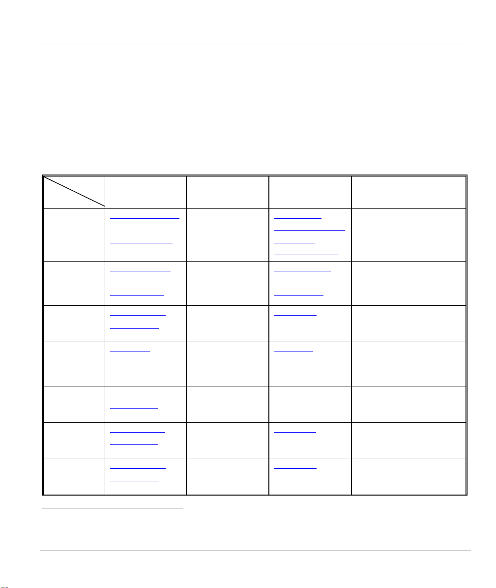
SUPPORT E-MAIL TELEPHONE1 WEB SITE METHOD
SALES E-MAIL FAX1 FTP SITE
support@zyxel.com.tw +886-3-578-3942 www.zyxel.com
sales@zyxel.com.tw
support@zyxel.com +1-800-255-4101
sales@zyxel.com
support@zyxel.de +49-2405-6909-0 www.zyxel.de GERMANY
sales@zyxel.de
support@zyxel.es +34 902 195 420 SPAIN
sales@zyxel.es
support@zyxel.dk +45 39 55 07 00 www.zyxel.dk DENMARK
sales@zyxel.dk
support@zyxel.no +47 22 80 61 80 www.zyxel.no NORWAY
sales@zyxel.no
+886-3-578-2439 ftp.zyxel.com
+1-714-632-0882
+1-714-632-0858 ftp.us.zyxel.com
+49-2405-6909-99
+33 (0)4 72 52 97 97 FRANCE info@zyxel.fr
+33 (0)4 72 52 19 20
+34 913 005 345
+45 39 55 07 07
+47 22 80 61 81
www.europe.zyxel.com
ftp.europe.zyxel.com
www.us.zyxel.com NORTH
www.zyxel.fr ZyXEL France
www.zyxel.es
ZyXEL Communications
1
“+” is the (prefix) number you enter to make an international telephone call.
Customer Support v
Prestige 660R ADSL 2+ Access Gateway
LOCATION
SUPPORT E-MAIL TELEPHONE1 WEB SITE METHOD
SALES E-MAIL FAX1 FTP SITE
support@zyxel.se +46 31 744 7700 www.zyxel.se SWEDEN
sales@zyxel.se
support@zyxel.fi +358-9-4780-8411 www.zyxel.fi FINLAND
sales@zyxel.fi
+46 31 744 7701
+358-9-4780 8448
REGULAR MAIL
ZyXEL Communications A/S
Sjöporten 4, 41764 Göteborg
Sweden
ZyXEL Communications Oy
Malminkaari 10
00700 Helsinki
Finland
vi Customer Support

Prestige 660R ADSL 2+ Access Gateway
Table of Contents
Copyright.........................................................................................................................................................ii
Federal Communications Commission (FCC) Interference Statement.....................................................iii
ZyXEL Limited Warranty.............................................................................................................................iv
Customer Support........................................................................................................................................... v
List of Figures................................................................................................................................................xii
List of Tables.................................................................................................................................................xvi
List of Charts..............................................................................................................................................xviii
Preface...........................................................................................................................................................xix
Introduction to DSL....................................................................................................................................xxii
Getting Started ................................................................................................................................................ I
Chapter 1 Getting To Know Your Prestige.................................................................................................1-1
1.1 Introducing the Prestige .............................................................................................................1-1
1.2 Features of the Prestige ..............................................................................................................1-2
1.3 Applications for the Prestige......................................................................................................1-5
Chapter 2 Introducing the Web Configurator...........................................................................................2-1
2.1 Web Configurator Overview......................................................................................................2-1
2.2 Accessing the Prestige Web Configurator..................................................................................2-1
2.3 Resetting the Prestige.................................................................................................................2-2
2.4 Navigating the Prestige Web Configurator ................................................................................2-2
Chapter 3 Wizard Setup..............................................................................................................................3-1
3.1 Wizard Setup Introduction .........................................................................................................3-1
3.2 Encapsulation .............................................................................................................................3-1
3.3 Multiplexing...............................................................................................................................3-2
3.4 VPI and VCI...............................................................................................................................3-2
3.5 Wizard Setup Configuration: First Screen .................................................................................3-2
3.6 IP Address and Subnet Mask .....................................................................................................3-4
3.7 IP Address Assignment..............................................................................................................3-4
3.8 Nailed-Up Connection (PPP) .....................................................................................................3-6
3.9 NAT ...........................................................................................................................................3-6
3.10 Wizard Setup Configuration: Second Screen.............................................................................3-6
3.11 DHCP Setup.............................................................................................................................3-11
3.12 Wizard Setup Configuration: Third Screen..............................................................................3-12
3.13 Wizard Setup Configuration: Connection Tests.......................................................................3-14
3.14 Test Your Internet Connection.................................................................................................3-15
Password, LAN and WAN .............................................................................................................................II
Chapter 4 Password Setup ..........................................................................................................................4-1
4.1 Password Overview....................................................................................................................4-1
4.2 Configuring Password................................................................................................................4-1
Table of Contents vii

Prestige 660R ADSL 2+ Access Gateway
Chapter 5 LAN Setup.................................................................................................................................. 5-1
5.1 LAN Overview ..........................................................................................................................5-1
5.2 DNS Server Address..................................................................................................................5-1
5.3 DNS Server Address Assignment..............................................................................................5-2
5.4 LAN TCP/IP ..............................................................................................................................5-2
5.5 Configuring LAN....................................................................................................................... 5-4
Chapter 6 WAN Setup .................................................................................................................................6-1
6.1 WAN Overview ......................................................................................................................... 6-1
6.2 Metric......................................................................................................................................... 6-1
6.3 PPPoE Encapsulation.................................................................................................................6-1
6.4 Traffic Shaping ..........................................................................................................................6-2
6.5 Configuring WAN Setup ...........................................................................................................6-3
6.6 Traffic Redirect.......................................................................................................................... 6-7
6.7 Configuring WAN Backup ........................................................................................................6-8
NAT, Dynamic DNS and Time and Date.....................................................................................................III
Chapter 7 Network Address Translation (NAT) Screens.......................................................................... 7-1
7.1 NAT Overview ..........................................................................................................................7-1
7.2 SUA (Single User Account) Versus NAT .................................................................................7-4
7.3 SUA Server................................................................................................................................7-5
7.4 Selecting the NAT Mode ...........................................................................................................7-6
7.5 Configuring SUA Server............................................................................................................7-7
7.6 Configuring Address Mapping...................................................................................................7-9
7.7 Editing an Address Mapping Rule ........................................................................................... 7-11
Chapter 8 Dynamic DNS Setup ..................................................................................................................8-1
8.1 Dynamic DNS............................................................................................................................ 8-1
8.2 Configuring Dynamic DNS .......................................................................................................8-1
Chapter 9 Time and Date ............................................................................................................................ 9-1
9.1 Configuring Time and Date .......................................................................................................9-1
Remote Management and UPnP..................................................................................................................IV
Chapter 10 Remote Management Configuration....................................................................................10-1
10.1 Remote Management Overview...............................................................................................10-1
10.2 Telnet .......................................................................................................................................10-2
10.3 FTP ..........................................................................................................................................10-2
10.4 Web.......................................................................................................................................... 10-2
10.5 Configuring Remote Management........................................................................................... 10-3
Chapter 11 Universal Plug-and-Play (UPnP) .......................................................................................... 11-1
11.1 Introducing Universal Plug and Play .......................................................................................11-1
11.2 UPnP and ZyXEL .................................................................................................................... 11-2
11.3 Installing UPnP in Windows Example.....................................................................................11-3
11.4 Using UPnP in Windows XP Example .................................................................................... 11-5
Maintenance ................................................................................................................................................... V
viii Table of Contents

Prestige 660R ADSL 2+ Access Gateway
Chapter 12 Maintenance ...........................................................................................................................12-1
12.1 Maintenance Overview ............................................................................................................12-1
12.2 System Status Screen ...............................................................................................................12-1
12.3 DHCP Table Screen .................................................................................................................12-6
12.4 Diagnostic Screens ...................................................................................................................12-7
12.5 Firmware Screen ......................................................................................................................12-9
SMT General Configuration ....................................................................................................................... VI
Chapter 13 Introducing the SMT .............................................................................................................13-1
13.1 SMT Introduction.....................................................................................................................13-1
13.2 Navigating the SMT Interface..................................................................................................13-3
13.3 Changing the System Password ...............................................................................................13-5
Chapter 14 Menu 1 General Setup ...........................................................................................................14-1
14.1 General Setup...........................................................................................................................14-1
14.2 Procedure To Configure Menu 1..............................................................................................14-1
Chapter 15 Menu 2 WAN Backup Setup..................................................................................................15-1
15.1 Introduction to WAN Backup Setup ........................................................................................15-1
15.2 Configuring Dial Backup in Menu 2........................................................................................15-1
Chapter 16 Menu 3 LAN Setup ................................................................................................................16-1
16.1 LAN Setup ...............................................................................................................................16-1
16.2 Protocol Dependent Ethernet Setup .........................................................................................16-2
16.3 TCP/IP Ethernet Setup and DHCP...........................................................................................16-2
Chapter 17 Internet Access .......................................................................................................................17-1
17.1 Internet Access Overview ........................................................................................................17-1
17.2 IP Policies ................................................................................................................................17-1
17.3 IP Alias.....................................................................................................................................17-1
17.4 IP Alias Setup...........................................................................................................................17-2
17.5 Route IP Setup..........................................................................................................................17-4
17.6 Internet Access Configuration..................................................................................................17-4
Chapter 18 Remote Node Configuration..................................................................................................18-1
18.1 Remote Node Setup Overview.................................................................................................18-1
18.2 Remote Node Setup..................................................................................................................18-1
18.3 Remote Node Network Layer Options.....................................................................................18-6
18.4 Remote Node Filter ..................................................................................................................18-8
18.5 Editing ATM Layer Options ..................................................................................................18-12
Chapter 19 Static Route Setup..................................................................................................................19-1
19.1 IP Static Route Overview.........................................................................................................19-1
19.2 Configuration ...........................................................................................................................19-2
Chapter 20 Bridging Setup........................................................................................................................20-1
20.1 Bridging in General..................................................................................................................20-1
20.2 Bridge Ethernet Setup ..............................................................................................................20-1
Chapter 21 Network Address Translation (NAT)....................................................................................21-1
Table of Contents ix

Prestige 660R ADSL 2+ Access Gateway
21.1 Using NAT...............................................................................................................................21-1
21.2 Applying NAT .........................................................................................................................21-1
21.3 NAT Setup ............................................................................................................................... 21-3
21.4 Configuring a Server behind NAT........................................................................................... 21-9
21.5 General NAT Examples.........................................................................................................21-11
SMT Advanced Management..................................................................................................................... VII
Chapter 22 Filter Configuration............................................................................................................... 22-1
22.1 About Filtering......................................................................................................................... 22-1
22.2 Configuring a Filter Set for the Prestige ..................................................................................22-4
22.3 Filter Rules Summary Menus ..................................................................................................22-6
22.4 Configuring a Filter Rule ......................................................................................................... 22-7
22.5 Filter Types and NAT ............................................................................................................22-14
22.6 Example Filter........................................................................................................................22-14
22.7 Applying Filters and Factory Defaults...................................................................................22-17
Chapter 23 SNMP Configuration.............................................................................................................23-1
23.1 About SNMP............................................................................................................................23-1
23.2 Supported MIBs.......................................................................................................................23-2
23.3 SNMP Configuration ...............................................................................................................23-2
23.4 SNMP Traps ............................................................................................................................23-4
Chapter 24 System Information and Diagnosis.......................................................................................24-1
24.1 System Status...........................................................................................................................24-1
24.2 System Information..................................................................................................................24-3
24.3 Log and Trace ..........................................................................................................................24-5
24.4 Diagnostic ................................................................................................................................ 24-8
Chapter 25 Firmware and Configuration File Maintenance .................................................................25-1
25.1 Filename Conventions .............................................................................................................25-1
25.2 Backup Configuration..............................................................................................................25-2
25.3 Restore Configuration..............................................................................................................25-6
25.4 Uploading Firmware and Configuration Files .........................................................................25-7
Chapter 26 System Maintenance.............................................................................................................. 26-1
26.1 Command Interpreter Mode.....................................................................................................26-1
26.2 Call Control Support................................................................................................................ 26-2
26.3 Time and Date Setting .............................................................................................................26-4
Chapter 27 Remote Management.............................................................................................................27-1
27.1 Remote Management Overview...............................................................................................27-1
27.2 Remote Management ...............................................................................................................27-1
27.3 Remote Management and NAT ...............................................................................................27-3
27.4 System Timeout ....................................................................................................................... 27-3
Chapter 28 IP Policy Routing ...................................................................................................................28-1
28.1 IP Policy Routing Overview ....................................................................................................28-1
28.2 Benefits of IP Policy Routing ..................................................................................................28-1
x Table of Contents

Prestige 660R ADSL 2+ Access Gateway
28.3 Routing Policy..........................................................................................................................28-1
28.4 IP Routing Policy Setup...........................................................................................................28-2
28.5 Applying an IP Policy ..............................................................................................................28-5
28.6 IP Policy Routing Example ......................................................................................................28-6
Chapter 29 Call Scheduling.......................................................................................................................29-1
29.1 Introduction..............................................................................................................................29-1
Appendices and Index............................................................................................................................... VIII
Appendix A Troubleshooting......................................................................................................................A-1
Appendix B IP Subnetting.......................................................................................................................... B-1
Appendix C PPPoE .....................................................................................................................................C-1
Appendix D Virtual Circuit Topology .......................................................................................................D-1
Appendix E Setting up Your Computer’s IP Address ..............................................................................E-1
Appendix F Splitters and Microfilters....................................................................................................... F-1
Appendix G Log Descriptions................................................................................................................... G-1
Appendix H Index ...................................................................................................................................... H-1
Table of Contents xi

Prestige 660R ADSL 2+ Access Gateway
List of Figures
Figure 1-1 Prestige Internet Access Application.............................................................................................1-6
Figure 1-2 Prestige LAN-to-LAN Application ...............................................................................................1-6
Figure 2-1 Password Screen ...........................................................................................................................2-1
Figure 2-2 Web Configurator SITE MAP Screen ...........................................................................................2-3
Figure 3-1 Wizard Screen 1 ............................................................................................................................3-3
Figure 3-2 Internet Connection with PPPoE...................................................................................................3-6
Figure 3-3 Internet Connection with RFC 1483 .............................................................................................3-8
Figure 3-4 Internet Connection with ENET ENCAP......................................................................................3-9
Figure 3-5 Internet Connection with PPPoA ................................................................................................3-10
Figure 3-6 Wizard Screen 3 ..........................................................................................................................3-12
Figure 3-7 Wizard : LAN Configuration.......................................................................................................3-13
Figure 3-8 Wizard Screen 4 ..........................................................................................................................3-14
Figure 4-1 Password .......................................................................................................................................4-1
Figure 5-1 LAN and WAN IP Addresses ........................................................................................................5-1
Figure 5-2 LAN ..............................................................................................................................................5-4
Figure 6-1 Example of Traffic Shaping ..........................................................................................................6-3
Figure 6-2 WAN Setup .....................................................................................................................................6-4
Figure 6-3 Traffic Redirect Example ..............................................................................................................6-8
Figure 6-4 Traffic Redirect LAN Setup ..........................................................................................................6-8
Figure 6-5 WAN Backup ..................................................................................................................................6-9
Figure 7-1 How NAT Works...........................................................................................................................7-2
Figure 7-2 NAT Application With IP Alias.....................................................................................................7-3
Figure 7-3 Multiple Servers Behind NAT Example........................................................................................7-6
Figure 7-4 NAT Mode.....................................................................................................................................7-7
Figure 7-5 Edit SUA/NAT Server Set.............................................................................................................7-8
Figure 7-6 Address Mapping Rules ..............................................................................................................7-10
Figure 7-7 Address Mapping Rule Edit ........................................................................................................7-11
Figure 8-1 DDNS............................................................................................................................................8-2
Figure 9-1 Time and Date ...............................................................................................................................9-1
Figure 10-1 Telnet Configuration on a TCP/IP Network ..............................................................................10-2
Figure 10-2 Remote Management ................................................................................................................10-3
Figure 11-1 Configuring UPnP..................................................................................................................... 11-2
Figure 12-1 System Status............................................................................................................................12-2
Figure 12-2 System Status: Show Statistics..................................................................................................12-4
Figure 12-3 DHCP Table ..............................................................................................................................12-6
Figure 12-4 Diagnostic General....................................................................................................................12-7
Figure 12-5 Diagnostic DSL Line.................................................................................................................12-8
Figure 12-6 Firmware Upgrade ..................................................................................................................12-10
xii List of Figures

Prestige 660R ADSL 2+ Access Gateway
Figure 12-7 Network Temporarily Disconnected........................................................................................12-11
Figure 12-8 Error Message..........................................................................................................................12-11
Figure 13-1 Login Screen ............................................................................................................................ 13-1
Figure 13-2 Prestige 660R SMT Menu Overview ....................................................................................... 13-2
Figure 13-3 SMT Main Menu...................................................................................................................... 13-4
Figure 13-4 Menu 23.1 Change Password ................................................................................................... 13-5
Figure 14-1 Menu 1 General Setup.............................................................................................................. 14-2
Figure 14-2 Menu 1.1 Configure Dynamic DNS......................................................................................... 14-3
Figure 15-1 Menu 2 WAN Backup Setup .................................................................................................... 15-1
Figure 15-2 Menu 2.1Traffic Redirect Setup ............................................................................................... 15-3
Figure 16-1 Menu 3 LAN Setup .................................................................................................................. 16-1
Figure 16-2 Menu 3.1 LAN Port Filter Setup .............................................................................................. 16-2
Figure 16-3 Menu 3.2 TCP/IP and DHCP Ethernet Setup ........................................................................... 16-3
Figure 17-1 Physical Network Figure 17-2 Partitioned Logical Networks ......................... 17-2
Figure 17-3 Menu 3.2 TCP/IP and DHCP Setup.......................................................................................... 17-2
Figure 17-4 Menu 3.2.1 IP Alias Setup ........................................................................................................ 17-3
Figure 17-5 Menu 1 General Setup.............................................................................................................. 17-4
Figure 17-6 Menu 4 Internet Access Setup .................................................................................................. 17-5
Figure 18-1 Menu 11 Remote Node Setup................................................................................................... 18-2
Figure 18-2 Menu 11.1 Remote Node Profile.............................................................................................. 18-3
Figure 18-3 Menu 11.3 Remote Node Network Layer Options................................................................... 18-6
Figure 18-4 Sample IP Addresses for a TCP/IP LAN-to-LAN Connection................................................. 18-8
Figure 18-5 Menu 11.5 Remote Node Filter (RFC 1483 or ENET Encapsulation) ..................................... 18-9
Figure 18-6 Menu 11.5 Remote Node Filter (PPPoA or PPPoE Encapsulation).......................................... 18-9
Figure 18-7 Internet Security ..................................................................................................................... 18-10
Figure 18-8 Menu 21- Filer Set Configuration ...........................................................................................18-11
Figure 18-9 Menu 21.11- WebSet 11 ..........................................................................................................18-11
Figure 18-10 Menu 21.12- WebSet 12 ........................................................................................................18-11
Figure 18-11 Menu 11.6 for VC-based Multiplexing................................................................................. 18-12
Figure 18-12 Menu 11.6 for LLC-based Multiplexing or PPP Encapsulation ........................................... 18-13
Figure 18-13 Menu 11.1 Remote Node Profile.......................................................................................... 18-13
Figure 18-14 Menu 11.8 Advance Setup Options ...................................................................................... 18-14
Figure 19-1 Sample Static Routing Topology .............................................................................................. 19-1
Figure 19-2 Menu 12 Static Route Setup..................................................................................................... 19-2
Figure 19-3 Menu 12.1 IP Static Route Setup.............................................................................................. 19-2
Figure 19-4 Menu12.1.1 Edit IP Static Route.............................................................................................. 19-3
Figure 20-1 Menu 11.1 Remote Node Profile.............................................................................................. 20-2
Figure 20-2 Menu 11.3 Remote Node Network Layer Options................................................................... 20-2
Figure 20-3 Menu 12.3.1 Edit Bridge Static Route...................................................................................... 20-3
Figure 21-1 Menu 4 Applying NAT for Internet Access .............................................................................. 21-2
Figure 21-2 Menu 11.3 Applying NAT to the Remote Node ....................................................................... 21-3
List of Figures xiii

Prestige 660R ADSL 2+ Access Gateway
Figure 21-3 Menu 15 NAT Setup..................................................................................................................21-4
Figure 21-4 Menu 15.1 Address Mapping Sets.............................................................................................21-4
Figure 21-5 Menu 15.1.255 SUA Address Mapping Rules ..........................................................................21-5
Figure 21-6 Menu 15.1.1 First Set................................................................................................................21-6
Figure 21-7 Menu 15.1.1.1 Editing/Configuring an Individual Rule in a Set...............................................21-8
Figure 21-8 Menu 15.2 NAT Server Setup ...................................................................................................21-9
Figure 21-9 Menu 15.2.1 NAT Server Setup ..............................................................................................21-10
Figure 21-10 Multiple Servers Behind NAT Example................................................................................21-11
Figure 21-11 NAT Example 1.....................................................................................................................21-11
Figure 21-12 Menu 4 Internet Access & NAT Example .............................................................................21-12
Figure 21-13 NAT Example 2.....................................................................................................................21-12
Figure 21-14 Menu 15.2.1 Specifying an Inside Server .............................................................................21-13
Figure 21-15 NAT Example 3.....................................................................................................................21-14
Figure 21-16 Example 3: Menu 11.3 .......................................................................................................... 21-15
Figure 21-17 Example 3: Menu 15.1.1.1 ....................................................................................................21-15
Figure 21-18 Example 3: Final Menu 15.1.1..............................................................................................21-16
Figure 21-19 NAT Example 4.....................................................................................................................21-17
Figure 21-20 Example 4: Menu 15.1.1.1 Address Mapping Rule...............................................................21-18
Figure 21-21 Example 4: Menu 15.1.1 Address Mapping Rules ................................................................ 21-18
Figure 22-1 Outgoing Packet Filtering Process ............................................................................................22-2
Figure 22-2 Filter Rule Process ....................................................................................................................22-3
Figure 22-3 Menu 21 Filter Set Configuration .............................................................................................22-4
Figure 22-4 NetBIOS_WAN Filter Rules Summary.....................................................................................22-5
Figure 22-5 NetBIOS_LAN Filter Rules Summary......................................................................................22-5
Figure 22-6 IGMP Filter Rules Summary.....................................................................................................22-5
Figure 22-7 Menu 21.x.1 TCP/IP Filter Rule................................................................................................22-8
Figure 22-8 Executing an IP Filter..............................................................................................................22-11
Figure 22-9 Menu 21.5.1 Generic Filter Rule ............................................................................................22-12
Figure 22-10 Protocol and Device Filter Sets.............................................................................................22-14
Figure 22-11 Sample Telnet Filter ..............................................................................................................22-15
Figure 22-12 Menu 21.6.1 Sample Filter....................................................................................................22-16
Figure 22-13 Menu 21.6 Sample Filter Rules Summary ............................................................................22-17
Figure 22-14 Filtering Ethernet Traffic.......................................................................................................22-18
Figure 22-15 Filtering Remote Node Traffic ..............................................................................................22-19
Figure 23-1 SNMP Management Model.......................................................................................................23-1
Figure 23-2 Menu 22 SNMP Configuration .................................................................................................23-3
Figure 24-1 Menu 24 System Maintenance..................................................................................................24-1
Figure 24-2 Menu 24.1 System Maintenance : Status ..................................................................................24-2
Figure 24-3 Menu 24.2 System Information and Console Port Speed..........................................................24-3
Figure 24-4 Menu 24.2.1 System Maintenance : Information ......................................................................24-4
Figure 24-5 Menu 24.2.2 System Maintenance : Change Console Port Speed.............................................24-5
xiv List of Figures

Prestige 660R ADSL 2+ Access Gateway
Figure 24-6 Menu 24.3 System Maintenance : Log and Trace .................................................................... 24-5
Figure 24-7 Sample Error and Information Messages ................................................................................. 24-6
Figure 24-8 Menu 24.3.2 System Maintenance : Syslog and Accounting.................................................... 24-6
Figure 24-9 Menu 24.4 System Maintenance : Diagnostic.......................................................................... 24-9
Figure 25-1 Telnet in Menu 24.5.................................................................................................................. 25-2
Figure 25-2 FTP Session Example............................................................................................................... 25-3
Figure 25-3 Telnet into Menu 24.6............................................................................................................... 25-6
Figure 25-4 Restore Using FTP Session Example ....................................................................................... 25-7
Figure 25-5 Telnet Into Menu 24.7.1 Upload System Firmware.................................................................. 25-8
Figure 25-6 Telnet Into Menu 24.7.2 System Maintenance ......................................................................... 25-8
Figure 25-7 FTP Session Example of Firmware File Upload ...................................................................... 25-9
Figure 26-1 Command Mode in Menu 24.................................................................................................... 26-1
Figure 26-2 Valid Commands ...................................................................................................................... 26-2
Figure 26-3 Menu 24.9 System Maintenance : Call Control........................................................................ 26-2
Figure 26-4 Menu 24.9.1 System Maintenance : Budget Management ....................................................... 26-3
Figure 26-5 Menu 24 System Maintenance ................................................................................................. 26-4
Figure 26-6 Menu 24.10 System Maintenance: Time and Date Setting....................................................... 26-4
Figure 27-1 Menu 24.11 Remote Management Control............................................................................... 27-2
Figure 28-1 Menu 25 IP Routing Policy Setup ............................................................................................ 28-2
Figure 28-2 Menu 25.1 IP Routing Policy Setup ......................................................................................... 28-3
Figure 28-3 Menu 25.1.1 IP Routing Policy ................................................................................................ 28-4
Figure 28-4 Menu 3.2 TCP/IP and DHCP Ethernet Setup ........................................................................... 28-6
Figure 28-5 Menu 11.3 Remote Node Network Layer Options................................................................... 28-6
Figure 28-6 Example of IP Policy Routing.................................................................................................. 28-7
Figure 28-7 IP Routing Policy Example ...................................................................................................... 28-8
Figure 28-8 IP Routing Policy Example ...................................................................................................... 28-9
Figure 28-9 Applying IP Policies Example .................................................................................................. 28-9
Figure 29-1 Menu 26 Schedule Setup.......................................................................................................... 29-1
Figure 29-2 Menu 26.1 Schedule Set Setup................................................................................................. 29-2
Figure 29-3 Applying Schedule Set(s) to a Remote Node (PPPoE)............................................................. 29-4
List of Figures xv

Prestige 660R ADSL 2+ Access Gateway
List of Tables
Table 2-1 Web Configurator Screens Summary..............................................................................................2-3
Table 3-1 Wizard Screen 1..............................................................................................................................3-3
Table 3-2 Internet Connection with PPPoE ....................................................................................................3-7
Table 3-3 Internet Connection with RFC 1483...............................................................................................3-8
Table 3-4 Internet Connection with ENET ENCAP .......................................................................................3-9
Table 3-5 Internet Connection with PPPoA.................................................................................................. 3-11
Table 3-6 Wizard : LAN Configuration ........................................................................................................3-13
Table 4-1 Password.........................................................................................................................................4-1
Table 5-1 LAN................................................................................................................................................5-4
Table 6-1 WAN Setup .......................................................................................................................................6-5
Table 6-2 WAN Backup..................................................................................................................................6-10
Table 7-1 NAT Definitions..............................................................................................................................7-1
Table 7-2 NAT Mapping Types.......................................................................................................................7-4
Table 7-3 Services and Port Numbers.............................................................................................................7-5
Table 7-4 NAT Mode ......................................................................................................................................7-7
Table 7-5 Edit SUA/NAT Server Set ..............................................................................................................7-8
Table 7-6 Address Mapping Rules................................................................................................................7-10
Table 7-7 Address Mapping Rule Edit..........................................................................................................7-12
Table 8-1 DDNS .............................................................................................................................................8-2
Table 9-1 Time and Date.................................................................................................................................9-2
Table 10-1 Remote Management..................................................................................................................10-3
Table 11-1 Configuring UPnP.......................................................................................................................11-2
Table 12-1 System Status..............................................................................................................................12-3
Table 12-2 System Status: Show Statistics ...................................................................................................12-5
Table 12-3 DHCP Table................................................................................................................................12-6
Table 12-4 Diagnostic General .....................................................................................................................12-8
Table 12-5 Diagnostic DSL Line ..................................................................................................................12-9
Table 12-6 Firmware Upgrade....................................................................................................................12-10
Table 13-1 Main Menu Commands ..............................................................................................................13-3
Table 13-2 Main Menu Summary.................................................................................................................13-4
Table 14-1 Menu 1 General Setup ................................................................................................................14-2
Table 14-2 Menu 1.1 Configure Dynamic DNS ...........................................................................................14-3
Table 15-1 Menu 2 WAN Backup Setup....................................................................................................... 15-1
Table 15-2 Menu 2.1Traffic Redirect Setup..................................................................................................15-3
Table 16-1 DHCP Ethernet Setup .................................................................................................................16-3
Table 16-2 TCP/IP Ethernet Setup................................................................................................................16-4
Table 17-1 Menu 3.2.1 IP Alias Setup ..........................................................................................................17-3
Table 17-2 Menu 4 Internet Access Setup ....................................................................................................17-5
xvi List of Tables

Prestige 660R ADSL 2+ Access Gateway
Table 18-1 Menu 11.1 Remote Node Profile................................................................................................ 18-3
Table 18-2 Menu 11.3 Remote Node Network Layer Options..................................................................... 18-6
Table 18-3 Menu 11.8 Advance Setup Options .......................................................................................... 18-14
Table 19-1 Menu12.1.1 Edit IP Static Route................................................................................................ 19-3
Table 20-1 Remote Node Network Layer Options : Bridge Fields.............................................................. 20-3
Table 20-2 Menu 12.3.1 Edit Bridge Static Route ....................................................................................... 20-3
Table 21-1 Applying NAT in Menus 4 & 11.3 ............................................................................................. 21-3
Table 21-2 SUA Address Mapping Rules .................................................................................................... 21-5
Table 21-3 Menu 15.1.1 First Set................................................................................................................. 21-7
Table 21-4 Menu 15.1.1.1 Editing/Configuring an Individual Rule in a Set................................................ 21-8
Table 22-1 Abbreviations Used in the Filter Rules Summary Menu............................................................ 22-6
Table 22-2 Rule Abbreviations Used ........................................................................................................... 22-6
Table 22-3 Menu 21.x.1 TCP/IP Filter Rule ................................................................................................ 22-8
Table 22-4 Menu 21.5.1 Generic Filter Rule.............................................................................................. 22-13
Table 22-5 Filter Sets Table ....................................................................................................................... 22-18
Table 23-1 Menu 22 SNMP Configuration .................................................................................................. 23-3
Table 23-2 SNMP Traps............................................................................................................................... 23-4
Table 23-3 Ports and Permanent Virtual Circuits......................................................................................... 23-4
Table 24-1 Menu 24.1 System Maintenance : Status ................................................................................... 24-2
Table 24-2 Menu 24.2.1 System Maintenance : Information....................................................................... 24-4
Table 24-3 Menu 24.3.2 System Maintenance : Syslog and Accounting..................................................... 24-6
Table 24-4 Menu 24.4 System Maintenance Menu : Diagnostic ................................................................. 24-9
Table 25-1 Filename Conventions................................................................................................................ 25-2
Table 25-2 General Commands for GUI-based FTP Clients........................................................................ 25-3
Table 25-3 General Commands for GUI-based TFTP Clients ..................................................................... 25-5
Table 26-1 Menu 24.9.1 System Maintenance : Budget Management......................................................... 26-3
Table 26-2 Menu 24.10 System Maintenance: Time and Date Setting ........................................................ 26-5
Table 27-1 Menu 24.11 Remote Management Control ................................................................................ 27-2
Table 28-1 Menu 25.1 IP Routing Policy Setup........................................................................................... 28-3
Table 28-2 Menu 25.1.1 IP Routing Policy.................................................................................................. 28-4
Table 29-1 Menu 26.1 Schedule Set Setup................................................................................................... 29-2
List of Tables xvii

Prestige 660R ADSL 2+ Access Gateway
List of Charts
Chart A-1 Troubleshooting the Start-Up of Your Prestige .............................................................................A-1
Chart A-2 Troubleshooting the LAN LED.....................................................................................................A-1
Chart A-3 Troubleshooting the DSL LED .....................................................................................................A-2
Chart A-4 Troubleshooting the LAN Interface ..............................................................................................A-2
Chart A-5 Troubleshooting the WAN Interface .............................................................................................A-2
Chart A-6 Troubleshooting Internet Access................................................................................................... A-3
Chart A-7 Troubleshooting the Password ......................................................................................................A-3
Chart A-8 Troubleshooting the Web Configurator......................................................................................... A-4
Chart A-9 Troubleshooting Remote Management .........................................................................................A-4
Chart B-1 Classes of IP Addresses................................................................................................................. B-1
Chart B-2 Allowed IP Address Range By Class ............................................................................................B-2
Chart B-3 “Natural” Masks............................................................................................................................ B-2
Chart B-4 Alternative Subnet Mask Notation ................................................................................................ B-3
Chart B-5 Subnet 1 ........................................................................................................................................B-4
Chart B-6 Subnet 2 ........................................................................................................................................B-4
Chart B-7 Subnet 1 ........................................................................................................................................B-5
Chart B-8 Subnet 2 ........................................................................................................................................B-5
Chart B-9 Subnet 3 ........................................................................................................................................B-5
Chart B-10 Subnet 4 ......................................................................................................................................B-6
Chart B-11 Eight Subnets .............................................................................................................................. B-6
Chart B-12 Class C Subnet Planning............................................................................................................. B-7
Chart B-13 Class B Subnet Planning............................................................................................................. B-7
Chart G-1 System Maintenance Logs............................................................................................................ G-1
Chart G-2 Access Logs ..................................................................................................................................G-2
Chart G-3 ICMP Notes ..................................................................................................................................G-2
xviii Lists of Charts

Prestige 660R ADSL 2+ Access Gateway
Preface
Congratulations on your purchase of the Prestige 660R ADSL 2+ Access Gateway.
Register your product online to receive e-mail notices of firmware upgrades and
information at www.zyxel.com for global products, or at www.us.zyxel.com for
North American products.
Your Prestige is easy to install and configure.
Use the web configurator, System Management Terminal (SMT) or command
interpreter interface to configure your ZyWALL. Not all features can be configured
through all interfaces.
The web configurator parts of this guide contain background information on features configurable by the
web configurator and the SMT. The SMT parts of this guide contain background information solely on
features not configurable by the web configurator.
About This User's Guide
This manual is designed to guide you through the configuration of your Prestige for its various applications.
The web configurator parts of this guide contain background information on features configurable by web
configurator. The SMT parts of this guide contain background information solely on features not
configurable by web configurator.
Use the web configurator, System Management Terminal (SMT) or command
interpreter interface to configure your Prestige. Not all features can be configured
through all interfaces.
Related Documentation
Supporting Disk
Refer to the included CD for support documents.
Compact Guide
The Compact Guide is designed to help you get up and running right away. They contain
connection information and instructions on getting started.
Web Configurator Online Help
Embedded web help for descriptions of individual screens and supplementary information.
ZyXEL Glossary and Web Site
Please refer to www.zyxel.com
documentation.
Preface xix
for an online glossary of networking terms and additional support

Prestige 660R ADSL 2+ Access Gateway
User Guide Feedback
Help us help you! E-mail all User Guide-related comments, questions or suggestions for improvement to
techwriters@zyxel.com.tw or send regular mail to The Technical Writing Team, ZyXEL Communications
Corp., 6 Innovation Road II, Science-Based Industrial Park, Hsinchu, 300, Taiwan. Thank you!
Syntax Conventions
• “Enter” means for you to type one or more characters. “Select” or “Choose” means for you to use one
predefined choices.
• The SMT menu titles and labels are in Bold Times New Roman font. Predefined field choices are in
Bold Arial font. Command and arrow keys are enclosed in square brackets. [ENTER] means the
Enter, or carriage return key; [ESC] means the Escape key and [SPACE BAR] means the Space Bar.
• Mouse action sequences are denoted using a comma. For example, “click the Apple icon, Control
Panels and then Modem” means first click the Apple icon, then point your mouse pointer to Control
Panels and then click Modem.
• For brevity’s sake, we will use “e.g.,” as a shorthand for “for instance”, and “i.e.,” for “that is” or “in
other words” throughout this manual.
• The Prestige 660R series may be referred to as the Prestige in this user’s guide. This refers to both
models (ADSL over POTS and ADSL over ISDN) unless specifically identified.
xx Preface
Prestige 660R ADSL 2+ Access Gateway
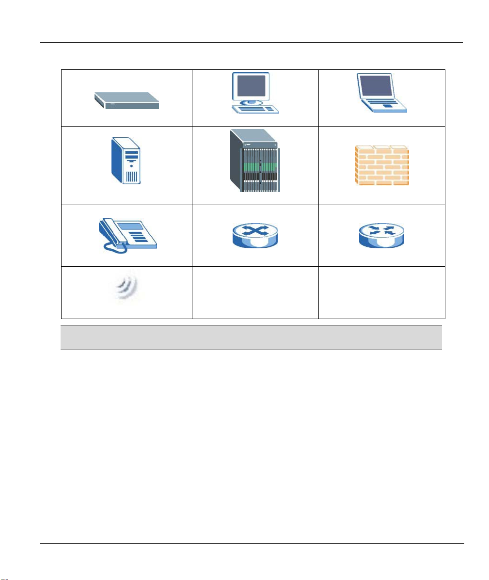
Graphics Icons Key
Prestige
Server
Telephone
Wireless Signal
Computer
DSLAM
Switch
Notebook computer
Firewall
Router
The following section offers some background information on DSL. Skip to
Chapter 1 if you wish to begin working with your router right away.
Preface xxi

Prestige 660R ADSL 2+ Access Gateway
Introduction to DSL
DSL (Digital Subscriber Line) technology enhances the data capacity of the existing twisted-pair wire that
runs between the local telephone company switching offices and most homes and offices. While the wire
itself can handle higher frequencies, the telephone switching equipment is designed to cut off signals above
4,000 Hz to filter noise off the voice line, but now everybody is searching for ways to get more bandwidth to
improve access to the Web - hence DSL technologies.
There are actually seven types of DSL service, ranging in speeds from 16 Kbits/sec to 52 Mbits/sec. The
services are either symmetrical (traffic flows at the same speed in both directions), or asymmetrical (the
downstream capacity is higher than the upstream capacity). Asymmetrical services (ADSL) are suitable for
Internet users because more information is usually downloaded than uploaded. For example, a simple button
click in a web browser can start an extended download that includes graphics and text.
As data rates increase, the carrying distance decreases. That means that users who are beyond a certain
distance from the telephone company’s central office may not be able to obtain the higher speeds.
A DSL connection is a point-to-point dedicated circuit, meaning that the link is always up and there is no
dialing required.
Introduction to ADSL
It is an asymmetrical technology, meaning that the downstream data rate is much higher than the upstream
data rate. As mentioned, this works well for a typical Internet session in which more information is
downloaded, for example, from Web servers, than is uploaded. ADSL operates in a frequency range that is
above the frequency range of voice services, so the two systems can operate over the same cable.
xxii What is DSL?

Getting Started
Part I:
Getting Started
This part is structured as a step-by-step guide to help you access your Prestige. It covers key
features and applications, accessing the web configurator and configuring the wizard screens for
initial setup.
I

Prestige 660R ADSL 2+ Access Gateway
Chapter 1
Getting To Know Your Prestige
This chapter describes the key features and applications of your Prestige.
1.1 Introducing the Prestige
Your Prestige integrates high-speed 10/100Mbps auto-negotiating LAN interface(s) and a high-speed ADSL
port into a single package. The Prestige is ideal for high-speed Internet browsing and making LAN-to-LAN
connections to remote networks. The Prestige is an ADSL router compatible with the
ADSL/ADSL2/ADSL2+ standards. Maximum data rates attainable by the Prestige for each standard are
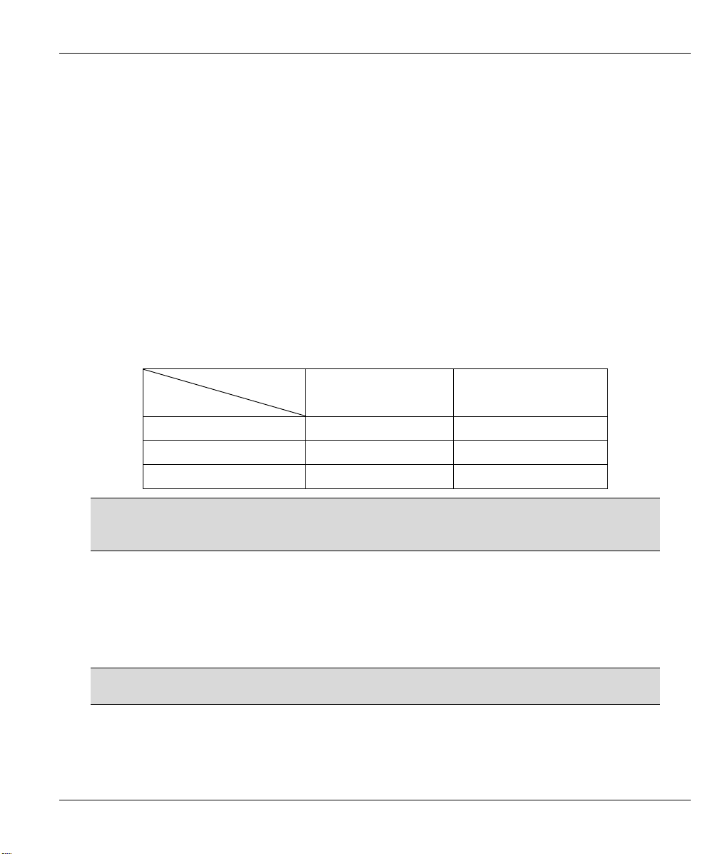
shown in the next table.
DATA RATE
STANDARD
ADSL
ADSL2
ADSL2+
The standard your ISP supports determines the maximum upstream and
downstream speeds attainable. Actual speeds attained also depend on the
distance from your ISP, noise, line quality, etc.
UPSTREAM DOWNSTREAM
832 kbps 8Mbps
3.5Mbps 12Mbps
3.5Mbps 24Mbps
By integrating DSL and NAT, the Prestige provides ease of installation and Internet access.
Models ending in “1”, for example P660R-61, denote a device that works over the analog telephone system,
POTS (Plain Old Telephone Service). Models ending in “3” denote a device that works over ISDN
(Integrated Synchronous Digital System). Models ending in “7” denote a device that works over T-ISDN
(UR-2).
Only use firmware for your Prestige’s specific model. Refer to the label on the
bottom of your Prestige.
The web browser-based Graphical User Interface provides easy management.
Getting To Know Your Prestige 1-1

Prestige 660R ADSL 2+ Access Gateway
1.2 Features of the Prestige
The following sections describe the features of the Prestige.
High Speed Internet Access
Your Prestige ADSL/ADSL2/ADSL2+ router can support downstream transmission rates of up to 24Mbps
and upstream transmission rates of up to 3.5Mbps. Actual speeds attained depend on ISP DSLAM
environment.
Traffic Redirect
Traffic redirect forwards WAN traffic to a backup gateway when the Prestige cannot connect to the Internet,
thus acting as an auxiliary if your regular WAN connection fails.
Universal Plug and Play (UPnP)
Using the standard TCP/IP protocol, the Prestige and other UPnP enabled devices can dynamically join a
network, obtain an IP address and convey its capabilities to other devices on the network.
PPPoE Support (RFC2516)
PPPoE (Point-to-Point Protocol over Ethernet) emulates a dial-up connection. It allows your ISP to use their
existing network configuration with newer broadband technologies such as ADSL. The PPPoE driver on the
Prestige is transparent to the computers on the LAN, which see only Ethernet and are not aware of PPPoE
thus saving you from having to manage PPPoE clients on individual computers.
Network Address Translation (NAT)
Network Address Translation (NAT) allows the translation of an Internet protocol address used within one
network (for example a private IP address used in a local network) to a different IP address known
within another network (for example a public IP address used on the Internet).
10/100M Auto-negotiating Ethernet/Fast Ethernet Interface(s)
This auto-negotiation feature allows the Prestige to detect the speed of incoming transmissions and adjust
appropriately without manual intervention. It allows data transfer of either 10 Mbps or 100 Mbps in either
half-duplex or full-duplex mode depending on your Ethernet network.
Auto-Crossover (MDI/MDI-X) 10/100 Mbps Ethernet Interface(s)
These interfaces automatically adjust to either a crossover or straight-through Ethernet cable.
1-2 Getting To Know Your Prestige

Prestige 660R ADSL 2+ Access Gateway
Dynamic DNS Support
With Dynamic DNS support, you can have a static hostname alias for a dynamic IP address, allowing the
host to be more easily accessible from various locations on the Internet. You must register for this service
with a Dynamic DNS service provider.
Multiple PVC (Permanent Virtual Circuits) Support
Your Prestige supports up to 8 PVC’s.
ADSL Transmission Rate Standards
♦ Full-Rate (ANSI T1.413, Issue 2; G.dmt (G.992.1) with line rate support of up to 8 Mbps
downstream and 832 Kbps upstream.
♦ G.lite (G.992.2) with line rate support of up to 1.5Mbps downstream and 512Kbps upstream.
♦ Supports Multi-Mode standard (ANSI T1.413, Issue 2; G.dmt (G.992.1); G.lite (G992.2)).
♦ TCP/IP (Transmission Control Protocol/Internet Protocol) network layer protocol.
♦ ATM Forum UNI 3.1/4.0 PVC.
♦ Supports up to 8 PVCs (UBR, CBR, VBR).
♦ Multiple Protocol over AAL5 (RFC 1483).
♦ PPP over AAL5 (RFC 2364).
♦ PPP over Ethernet over AAL5 (RFC 2516).
♦ RFC 1661.
♦ PPP over PAP (RFC 1334).
♦ PPP over CHAP (RFC 1994).
Protocol Support
♦ DHCP Support
DHCP (Dynamic Host Configuration Protocol) allows the individual clients (computers) to obtain
the TCP/IP configuration at start-up from a centralized DHCP server. The Prestige has built-in
DHCP server capability enabled by default. It can assign IP addresses, an IP default gateway and
DNS servers to DHCP clients. The Prestige can now also act as a surrogate DHCP server (DHCP
Relay) where it relays IP address assignment from the actual real DHCP server to the clients.
♦ IP Alias
Getting To Know Your Prestige 1-3

Prestige 660R ADSL 2+ Access Gateway
IP Alias allows you to partition a physical network into logical networks over the same Ethernet
interface. The Prestige supports three logical LAN interfaces via its single physical Ethernet
interface with the Prestige itself as the gateway for each LAN network.
♦ IP Policy Routing (IPPR)
Traditionally, routing is based on the destination address only and the router takes the shortest path
to forward a packet. IP Policy Routing (IPPR) provides a mechanism to override the default routing
behavior and alter the packet forwarding based on the policy defined by the network administrator.
♦ PPP (Point-to-Point Protocol) link layer protocol.
♦ Transparent bridging for unsupported network layer protocols.
♦ RIP I/RIP II
♦ IGMP Proxy
♦ ICMP support
♦ ATM QoS support
♦ MIB II support (RFC 1213)
Networking Compatibility
Your Prestige is compatible with the major ADSL DSLAM (Digital Subscriber Line Access Multiplexer)
providers, making configuration as simple as possible for you.
Multiplexing
The Prestige supports VC-based and LLC-based multiplexing.
Encapsulation
The Prestige supports PPPoA (RFC 2364 - PPP over ATM Adaptation Layer 5), RFC 1483 encapsulation
over ATM, MAC encapsulated routing (ENET encapsulation) as well as PPP over Ethernet (RFC 2516).
Network Management
♦ Menu driven SMT (System Management Terminal) management
♦ Embedded web configurator
♦ CLI (Command Line Interpreter)
♦ Remote Management via Telnet or Web.
♦ SNMP manageable
♦ DHCP Server/Client/Relay
1-4 Getting To Know Your Prestige

Prestige 660R ADSL 2+ Access Gateway
♦ Built-in Diagnostic Tools
♦ Syslog
♦ Telnet Support (Password-protected telnet access to internal configuration manager)
♦ TFTP/FTP server, firmware upgrade and configuration backup/support supported
♦ Supports OAM F4/F5 loop-back, AIS and RDI OAM cells
Other PPPoE Features
♦ PPPoE idle time out
♦ PPPoE Dial on Demand
Diagnostics Capabilities
The Prestige can perform self-diagnostic tests. These tests check the integrity of the following circuitry:
♦ FLASH memory
♦ ADSL circuitry
♦ RAM
♦ LAN port
Packet Filters
The Prestige's packet filtering functions allows added network security and management.
Ease of Installation
Your Prestige is designed for quick, intuitive and easy installation.
Housing
Your Prestige's compact and ventilated housing minimizes space requirements making it easy to position
anywhere in your busy office.
1.3 Applications for the Prestige
Here are some example uses for which the Prestige is well suited.
1.3.1 Internet Access
The Prestige is the ideal high-speed Internet access solution. Your Prestige supports the TCP/IP protocol,
which the Internet uses exclusively. It is compatible with all major ADSL DSLAM (Digital Subscriber Line
Getting To Know Your Prestige 1-5
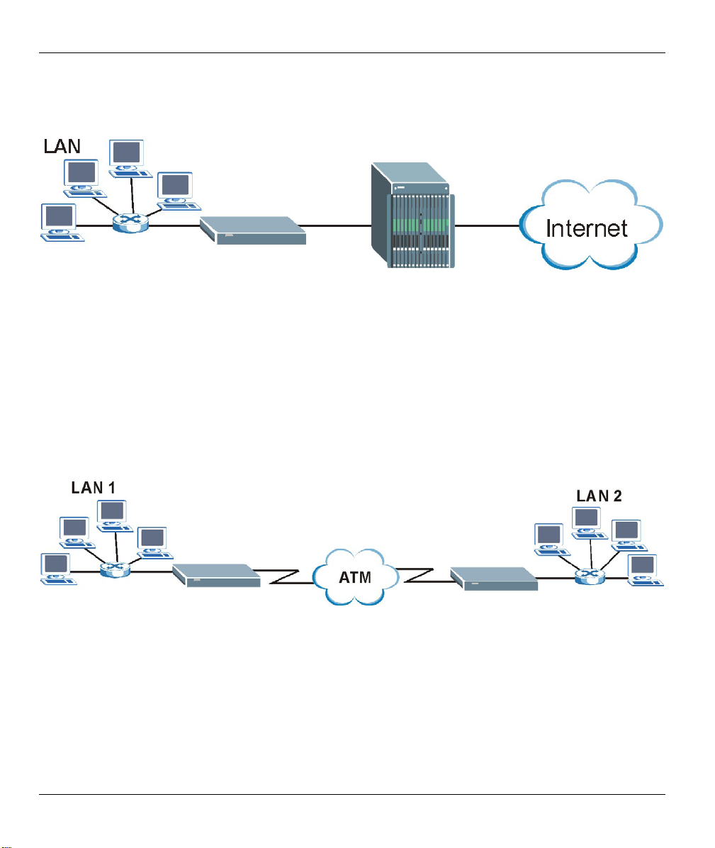
Prestige 660R ADSL 2+ Access Gateway
Access Multiplexer) providers. A DSLAM is a rack of ADSL line cards with data multiplexed into a
backbone network interface/connection (for example, T1, OC3, DS3, ATM or Frame Relay). Think of it as
the equivalent of a modem rack for ADSL. A typical Internet access application is shown below.
Figure 1-1 Prestige Internet Access Application
Internet Single User Account
For a SOHO (Small Office/Home Office) environment, your Prestige offers the Single User Account (SUA)
feature that allows multiple users on the LAN (Local Area Network) to access the Internet concurrently for
the cost of a single IP address.
1.3.2 LAN to LAN Application
You can use the Prestige to connect two geographically dispersed networks over the ADSL line. A typical
LAN-to-LAN application for your Prestige is shown as follows.
Figure 1-2 Prestige LAN-to-LAN Application
1-6 Getting To Know Your Prestige
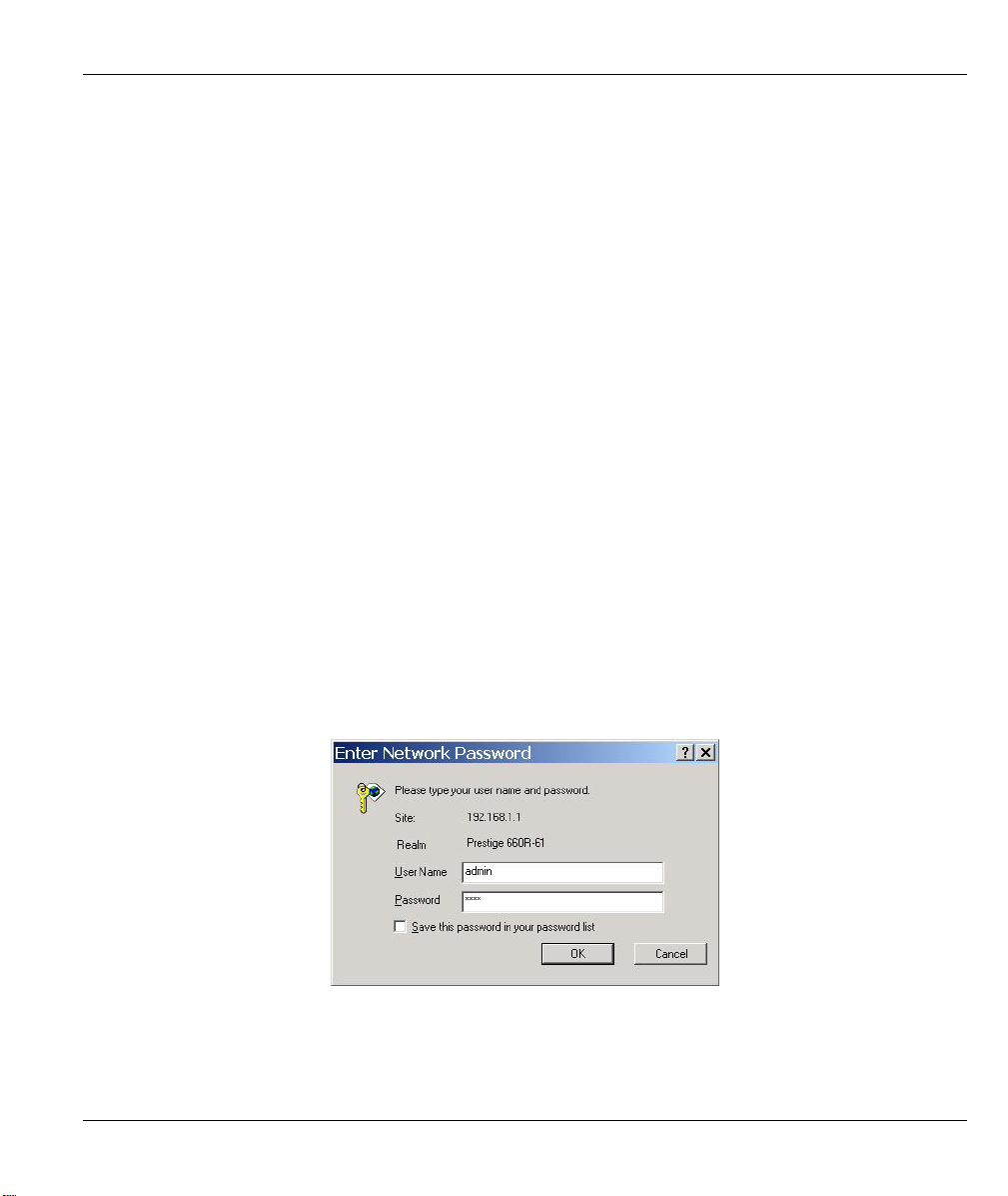
Prestige 660R ADSL 2+ Access Gateway
Chapter 2
Introducing the Web Configurator
This chapter describes how to access and navigate the web configurator.
2.1 Web Configurator Overview
The embedded web configurator allows you to manage the Prestige from anywhere through a browser such
as Microsoft Internet Explorer or Netscape Navigator. Use Internet Explorer 6.0 and later or Netscape
Navigator 7.0 and later versions with JavaScript enabled. It is recommended that you set your screen
resolution to 1024 by 768 pixels
2.2 Accessing the Prestige Web Configurator
Step 1. Make sure your Prestige hardware is properly connected (refer to the Read Me First).
Step 2. Prepare your computer/computer network to connect to the Prestige (refer to the Read Me
First).
Step 3. Launch your web browser.
Step 4. Type "192.168.1.1" as the URL.
Step 5. An Enter Network Password window displays. Enter the user name (“admin” is the default),
password (“1234” is the default) and click OK.
Figure 2-1 Password Screen
Step 6. You should now see the SITE MAP screen.
Introducing the Web Configurator 2-1

Prestige 660R ADSL 2+ Access Gateway
The Prestige automatically times out after five minutes of inactivity. Simply log
back into the Prestige if this happens to you.
2.3 Resetting the Prestige
If you forget your password or cannot access the web configurator, you will need to use the RESET button at
the back of the Prestige to reload the factory-default configuration file. This means that you will lose all
configurations that you had previously and the password will be reset to “1234”.
2.3.1 Using The Reset Button
Step 1. Make sure the SYS LED is on (not blinking).
Step 2. Press the RESET button for ten seconds or until the SYS LED begins to blink and then release it.
When the SYS LED begins to blink, the defaults have been restored and the Prestige restarts.
2.4 Navigating the Prestige Web Configurator
The following summarizes how to navigate the web configurator from the SITE MAP screen. We use the
Prestige 660HW-61 web screens in this guide as an example. Screens vary slightly for different Prestige
models.
Click Wizard Setup to begin a series of screens to configure your Prestige for the first time.
Click a link under Advanced Setup to configure advanced Prestige features.
Click a link under Maintenance to see Prestige performance statistics, upload firmware and back up,
restore or upload a configuration file.
Click SITE MAP to go to the Site Map screen.
Click Logout in the navigation panel when you have finished a Prestige management session.
2-2 Introducing the Web Configurator

Navigation panel
Prestige 660R ADSL 2+ Access Gateway
Wizard Setup
Logout
Figure 2-2 Web Configurator SITE MAP Screen
Click the icon (located in the top right corner of most screens) to view
embedded help.
Table 2-1 Web Configurator Screens Summary
LINK SUB-LINK FUNCTION
Wizard Setup Use these screens for initial configuration including general setup, ISP
parameters for Internet Access and WAN IP/DNS Server/MAC
address assignment.
Advanced Setup
Password Use this screen to change your password.
LAN Use this screen to configure LAN DHCP and TCP/IP settings.
WAN WAN Setup Use this screen to change the Prestige’s WAN remote node settings.
WAN Backup Use this screen to configure your traffic redirect properties and WAN
backup settings.
NAT SUA Only Use this screen to configure servers behind the Prestige.
Full Feature Use this screen to configure network address translation mapping
rules.
Dynamic DNS Use this screen to set up dynamic DNS.
Introducing the Web Configurator 2-3

Prestige 660R ADSL 2+ Access Gateway
Table 2-1 Web Configurator Screens Summary
LINK SUB-LINK FUNCTION
Time and Date Use this screen to change your Prestige’s time and date.
Remote
Management
UPnP Use this screen to enable UPnP on the Prestige.
Logs Log Settings Use this screen to change your Prestige’s log settings.
View Log Use this screen to view the logs for the categories that you selected.
Maintenance
System Status This screen contains administrative and system-related information.
DHCP Table This screen displays DHCP (Dynamic Host Configuration Protocol)
Diagnostic General These screens display information to help you identify problems with
DSL Line These screens display information to help you identify problems with
Firmware Use this screen to upload firmware or reset the factory defaults to your
LOGOUT Click this label to exit the web configurator.
Use this screen to configure through which interface(s) and from which
IP address(es) users can use Telnet/FTP/Web to manage the
Prestige.
related information and is READ-ONLY.
the Prestige general connection.
the DSL line.
Prestige
2-4 Introducing the Web Configurator

Prestige 660R ADSL 2+ Access Gateway
Chapter 3
Wizard Setup
This chapter provides information on the Wizard Setup screens in the web configurator.
3.1 Wizard Setup Introduction
Use the Wizard Setup screens to configure your system for Internet access settings and fill in the fields with
the information in the Internet Account Information table of the Read Me First. Your ISP may have already
configured some of the fields in the wizard screens for you.
3.2 Encapsulation
Be sure to use the encapsulation method required by your ISP. The Prestige supports the following methods.
3.2.1 ENET ENCAP
The MAC Encapsulated Routing Link Protocol (ENET ENCAP) is only implemented with the IP network
protocol. IP packets are routed between the Ethernet interface and the WAN interface and then formatted so
that they can be understood in a bridged environment. For instance, it encapsulates routed Ethernet frames
into bridged ATM cells. ENET ENCAP requires that you specify a gateway IP address in the ENET
ENCAP Gateway field in the second wizard screen. You can get this information from your ISP.
3.2.2 PPP over Ethernet
PPPoE provides access control and billing functionality in a manner similar to dial-up services using PPP.
The Prestige bridges a PPP session over Ethernet (PPP over Ethernet, RFC 2516) from your computer to an
ATM PVC (Permanent Virtual Circuit) which connects to ADSL Access Concentrator where the PPP session
terminates. One PVC can support any number of PPP sessions from your LAN. For more information on
PPPoE, see the appendix.
3.2.3 PPPoA
PPPoA stands for Point to Point Protocol over ATM Adaptation Layer 5 (AAL5). A PPPoA connection
functions like a dial-up Internet connection. The Prestige encapsulates the PPP session based on RFC1483
and sends it through an ATM PVC (Permanent Virtual Circuit) to the Internet Service Provider’s (ISP)
DSLAM (digital access multiplexer). Please refer to RFC 2364 for more information on PPPoA. Refer to
RFC 1661 for more information on PPP.
Wizard Setup 3-1

Prestige 660R ADSL 2+ Access Gateway
3.2.4 RFC 1483
RFC 1483 describes two methods for Multiprotocol Encapsulation over ATM Adaptation Layer 5 (AAL5).
The first method allows multiplexing of multiple protocols over a single ATM virtual circuit (LLC-based
multiplexing) and the second method assumes that each protocol is carried over a separate ATM virtual
circuit (VC-based multiplexing). Please refer to the RFC for more detailed information.
3.3 Multiplexing
There are two conventions to identify what protocols the virtual circuit (VC) is carrying. Be sure to use the
multiplexing method required by your ISP.
3.3.1 VC-based Multiplexing
In this case, by prior mutual agreement, each protocol is assigned to a specific virtual circuit; for example,
VC1 carries IP, etc. VC-based multiplexing may be dominant in environments where dynamic creation of
large numbers of ATM VCs is fast and economical.
3.3.2 LLC-based Multiplexing
In this case one VC carries multiple protocols with protocol identifying information being contained in each
packet header. Despite the extra bandwidth and processing overhead, this method may be advantageous if it
is not practical to have a separate VC for each carried protocol, for example, if charging heavily depends on
the number of simultaneous VCs.
3.4 VPI and VCI
Be sure to use the correct Virtual Path Identifier (VPI) and Virtual Channel Identifier (VCI) numbers
assigned to you. The valid range for the VPI is 0 to 255 and for the VCI is 32 to 65535 (0 to 31 is reserved
for local management of ATM traffic). Please see the appendix for more information.
3.5 Wizard Setup Configuration: First Screen
In the SITE MAP screen click Wizard Setup to display the first wizard screen.
3-2 Wizard Setup

Figure 3-1 Wizard Screen 1
The following table describes the fields in this screen.
Table 3-1 Wizard Screen 1
Prestige 660R ADSL 2+ Access Gateway
LABEL DESCRIPTION
Mode
Encapsulation
Multiplex
Virtual Circuit
ID
From the Mode drop-down list box, select Routing (default) if your ISP allows multiple
computers to share an Internet account. Otherwise select Bridge.
Select the encapsulation type your ISP uses from the Encapsulation drop-down list box.
Choices vary depending on what you select in the Mode field.
If you select Bridge in the Mode field, select either PPPoA or RFC 1483.
If you select Routing in the Mode field, select PPPoA, RFC 1483, ENET ENCAP or PPPoE.
Select the multiplexing method used by your ISP from the Multiplex drop-down list box either
VC-based or LLC-based.
VPI (Virtual Path Identifier) and VCI (Virtual Channel Identifier) define a virtual circuit. Refer to
the appendix for more information.
VPI Enter the VPI assigned to you. This field may already be configured.
VCI Enter the VCI assigned to you. This field may already be configured.
Wizard Setup 3-3

Prestige 660R ADSL 2+ Access Gateway
Table 3-1 Wizard Screen 1
LABEL DESCRIPTION
Next Click this button to go to the next wizard screen. The next wizard screen you see depends on
what protocol you chose above. Click on the protocol link to see the next wizard screen for
that protocol.
3.6 IP Address and Subnet Mask
Similar to the way houses on a street share a common street name, so too do computers on a LAN share one
common network number.
Where you obtain your network number depends on your particular situation. If the ISP or your network
administrator assigns you a block of registered IP addresses, follow their instructions in selecting the IP
addresses and the subnet mask.
If the ISP did not explicitly give you an IP network number, then most likely you have a single user account
and the ISP will assign you a dynamic IP address when the connection is established. If this is the case, it is
recommended that you select a network number from 192.168.0.0 to 192.168.255.0 and you must enable the
Network Address Translation (NAT) feature of the Prestige. The Internet Assigned Number Authority
(IANA) reserved this block of addresses specifically for private use; please do not use any other number
unless you are told otherwise. Let's say you select 192.168.1.0 as the network number; which covers 254
individual addresses, from 192.168.1.1 to 192.168.1.254 (zero and 255 are reserved). In other words, the first
three numbers specify the network number while the last number identifies an individual computer on that
network.
Once you have decided on the network number, pick an IP address that is easy to remember, for instance,
192.168.1.1, for your Prestige, but make sure that no other device on your network is using that IP address.
The subnet mask specifies the network number portion of an IP address. Your Prestige will compute the
subnet mask automatically based on the IP address that you entered. You don't need to change the subnet
mask computed by the Prestige unless you are instructed to do otherwise.
3.7 IP Address Assignment
A static IP is a fixed IP that your ISP gives you. A dynamic IP is not fixed; the ISP assigns you a different
one each time. The Single User Account feature can be enabled or disabled if you have either a dynamic or
static IP. However the encapsulation method assigned influences your choices for IP address and ENET
ENCAP Gateway.
3-4 Wizard Setup

Prestige 660R ADSL 2+ Access Gateway
3.7.1 IP Assignment with PPPoA or PPPoE Encapsulation
If you have a dynamic IP, then the IP Address and ENET ENCAP Gateway fields are not applicable (N/A). If
you have a static IP, then you only need to fill in the IP Address field and not the ENET ENCAP Gateway
field.
3.7.2 IP Assignment with RFC 1483 Encapsulation
In this case the IP Address Assignment must be static with the same requirements for the IP Address and
ENET ENCAP Gateway fields as stated above.
3.7.3 IP Assignment with ENET ENCAP Encapsulation
In this case you can have either a static or dynamic IP. For a static IP you must fill in all the IP Address and
ENET ENCAP Gateway fields as supplied by your ISP. However for a dynamic IP, the Prestige acts as a
DHCP client on the WAN port and so the IP Address and ENET ENCAP Gateway fields are not applicable
(N/A) as the DHCP server assigns them to the Prestige.
3.7.4 Private IP Addresses
Every machine on the Internet must have a unique address. If your networks are isolated from the Internet,
for example, only between your two branch offices, you can assign any IP addresses to the hosts without
problems. However, the Internet Assigned Numbers Authority (IANA) has reserved the following three
blocks of IP addresses specifically for private networks:
10.0.0.0 — 10.255.255.255
172.16.0.0 — 172.31.255.255
192.168.0.0 — 192.168.255.255
You can obtain your IP address from the IANA, from an ISP or it can be assigned from a private network. If
you belong to a small organization and your Internet access is through an ISP, the ISP can provide you with
the Internet addresses for your local networks. On the other hand, if you are part of a much larger
organization, you should consult your network administrator for the appropriate IP addresses.
Regardless of your particular situation, do not create an arbitrary IP address;
always follow the guidelines above. For more information on address assignment,
please refer to RFC 1597, Address Allocation for Private Internets and RFC 1466,
Guidelines for Management of IP Address Space.
Wizard Setup 3-5

Prestige 660R ADSL 2+ Access Gateway
3.8 Nailed-Up Connection (PPP)
A nailed-up connection is a dial-up line where the connection is always up regardless of traffic demand. The
Prestige does two things when you specify a nailed-up connection. The first is that idle timeout is disabled.
The second is that the Prestige will try to bring up the connection when turned on and whenever the
connection is down. A nailed-up connection can be very expensive for obvious reasons.
Do not specify a nailed-up connection unless your telephone company offers flat-rate service or you need a
constant connection and the cost is of no concern
3.9 NAT
NAT (Network Address Translation - NAT, RFC 1631) is the translation of the IP address of a host in a
packet, for example, the source address of an outgoing packet, used within one network to a different IP
address known within another network.
3.10 Wizard Setup Configuration: Second Screen
The second wizard screen varies depending on what mode and encapsulation type you use. All screens shown
are with routing mode. Configure the fields and click Next to continue.
Figure 3-2 Internet Connection with PPPoE
3-6 Wizard Setup

Prestige 660R ADSL 2+ Access Gateway
The following table describes the fields in this screen.
Table 3-2 Internet Connection with PPPoE
LABEL DESCRIPTION
Service Name Type the name of your PPPoE service here.
User Name Enter the user name exactly as your ISP assigned. If assigned a name in the form
user@domain
as given.
Password Enter the password associated with the user name above.
IP Address A static IP address is a fixed IP that your ISP gives you. A dynamic IP address is not fixed;
the ISP assigns you a different one each time you connect to the Internet. The Single User
Account feature can be used with either a dynamic or static IP address.
Select Obtain an IP Address Automatically if you have a dynamic IP address; otherwise
select Static IP Address and type your ISP assigned IP address in the IP Address text box
below.
where domain identifies a service name, then enter both components exactly
Connection
Network
Address
Translation
Back
Next
Select Connect on Demand when you don't want the connection up all the time and specify
an idle time-out (in seconds) in the Max. Idle Timeout field. The default setting selects
Connection on Demand with 0 as the idle time-out, which means the Internet session will
not timeout.
Select Nailed-Up Connection when you want your connection up all the time. The Prestige
will try to bring up the connection automatically if it is disconnected.
The schedule rule(s) in SMT menu 26 has priority over your Connection settings.
Select None, SUA Only or Full Feature from the drop-sown list box. Refer to the NAT
chapter for more details.
Click Back to go back to the first wizard screen.
Click Next to continue to the next wizard screen.
Wizard Setup 3-7
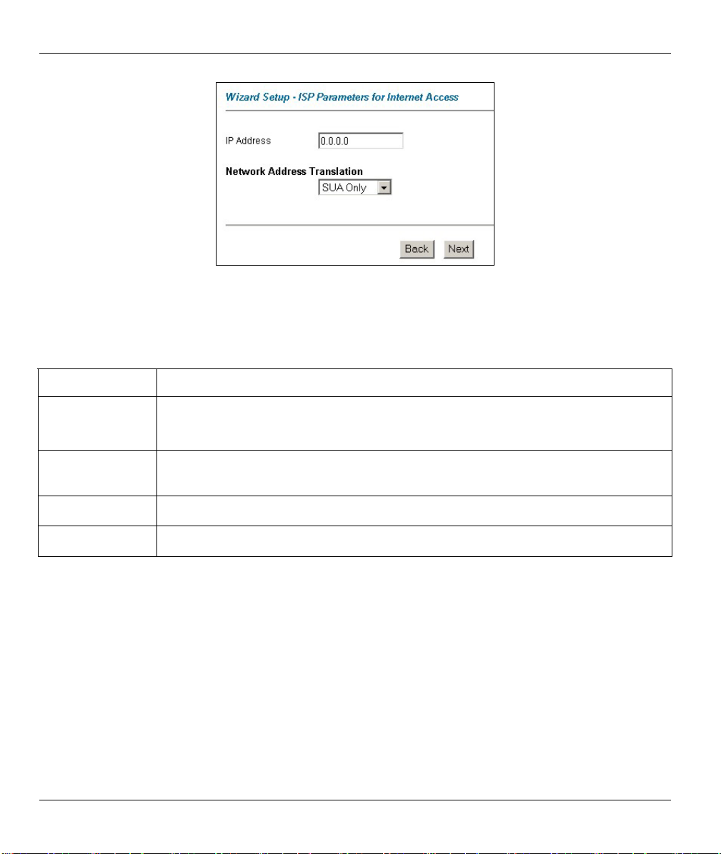
Prestige 660R ADSL 2+ Access Gateway
Figure 3-3 Internet Connection with RFC 1483
The following table describes the fields in this screen.
Table 3-3 Internet Connection with RFC 1483
LABEL DESCRIPTION
IP Address
Network Address
Translation
Back
Next
This field is available if you select Routing in the Mode field.
Type your ISP assigned IP address in this field.
Select None, SUA Only or Full Feature from the drop-sown list box. Refer to the NAT
chapter for more details.
Click Back to go back to the first wizard screen.
Click Next to continue to the next wizard screen.
3-8 Wizard Setup
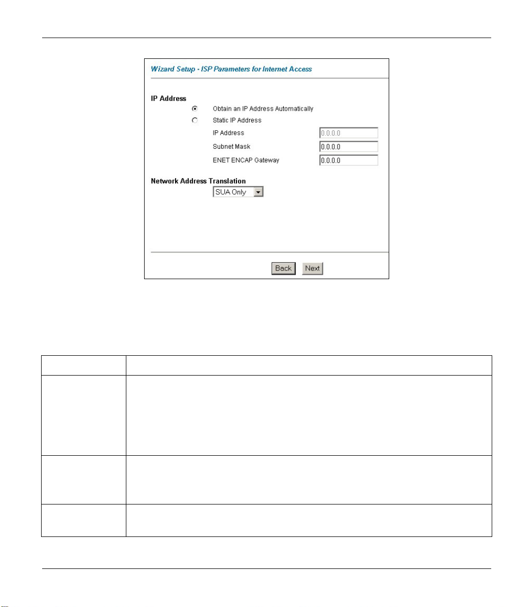
Figure 3-4 Internet Connection with ENET ENCAP
The following table describes the fields in this screen.
Prestige 660R ADSL 2+ Access Gateway
Table 3-4 Internet Connection with ENET ENCAP
LABEL DESCRIPTION
IP Address A static IP address is a fixed IP that your ISP gives you. A dynamic IP address is not
fixed; the ISP assigns you a different one each time you connect to the Internet. The
Single User Account feature can be used with either a dynamic or static IP address.
Select Obtain an IP Address Automatically if you have a dynamic IP address;
otherwise select Static IP Address and type your ISP assigned IP address in the IP
Address text box below.
Subnet Mask Enter a subnet mask in dotted decimal notation.
Refer to the IP Subnetting appendix to calculate a subnet mask If you are implementing
subnetting.
ENET ENCAP
Gateway
You must specify a gateway IP address (supplied by your ISP) when you use ENET
ENCAP in the Encapsulation field in the previous screen.
Wizard Setup 3-9

Prestige 660R ADSL 2+ Access Gateway
Table 3-4 Internet Connection with ENET ENCAP
LABEL DESCRIPTION
Network Address
Translation
Back
Next
Select None, SUA Only or Full Feature from the drop-sown list box. Refer to the NAT
chapter for more details.
Click Back to go back to the first wizard screen.
Click Next to continue to the next wizard screen.
Figure 3-5 Internet Connection with PPPoA
The following table describes the fields in this screen.
3-10 Wizard Setup

Prestige 660R ADSL 2+ Access Gateway
Table 3-5 Internet Connection with PPPoA
LABEL DESCRIPTION
User Name Enter the login name that your ISP gives you.
Password Enter the password associated with the user name above.
IP Address
Connection
Network
Address
Translation
Back
Next
This option is available if you select Routing in the Mode field.
A static IP address is a fixed IP that your ISP gives you. A dynamic IP address is not fixed;
the ISP assigns you a different one each time you connect to the Internet. The Single User
Account feature can be used with either a dynamic or static IP address.
Click Obtain an IP Address Automatically if you have a dynamic IP address; otherwise
click Static IP Address and type your ISP assigned IP address in the IP Address text box
below.
Select Connect on Demand when you don't want the connection up all the time and specify
an idle time-out (in seconds) in the Max. Idle Timeout field. The default setting selects
Connection on Demand with 0 as the idle time-out, which means the Internet session will
not timeout.
Select Nailed-Up Connection when you want your connection up all the time. The Prestige
will try to bring up the connection automatically if it is disconnected.
The schedule rule(s) in SMT menu 26 has priority over your Connection settings.
This option is available if you select Routing in the Mode field.
Select None, SUA Only or Full Feature from the drop-sown list box. Refer to the NAT
chapter for more details.
Click Back to go back to the first wizard screen.
Click Next to continue to the next wizard screen.
3.11 DHCP Setup
DHCP (Dynamic Host Configuration Protocol, RFC 2131 and RFC 2132) allows individual clients to obtain
TCP/IP configuration at start-up from a server. You can configure the Prestige as a DHCP server or disable
it. When configured as a server, the Prestige provides the TCP/IP configuration for the clients. If you turn
DHCP service off, you must have another DHCP server on your LAN, or else the computer must be
manually configured.
Wizard Setup 3-11
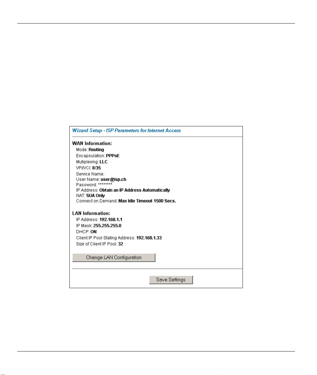
Prestige 660R ADSL 2+ Access Gateway
3.11.1 IP Pool Setup
The Prestige is pre-configured with a pool of 32 IP addresses starting from 192.168.1.33 to 192.168.1.64 for
the client machines. This leaves 31 IP addresses, 192.168.1.2 to 192.168.1.32 (excluding the Prestige itself
which has a default IP of 192.168.1.1) for other server machines, for example, server for mail, FTP, telnet,
web, etc., that you may have.
3.12 Wizard Setup Configuration: Third Screen
Step 1. Verify the settings in the screen shown next. To change the LAN information on the Prestige,
click Change LAN Configurations. Otherwise click Save Settings to save the configuration and
skip to the section 3.13.
Figure 3-6 Wizard Screen 3
Step 2. If you want to change your Prestige LAN settings, click Change LAN Configuration to display
the screen as shown next.
3-12 Wizard Setup
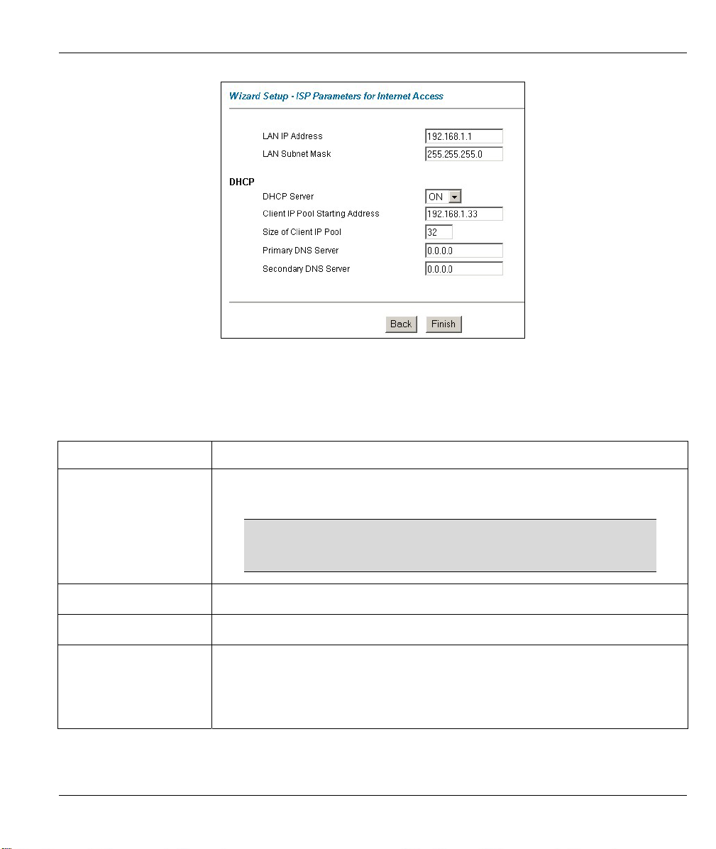
Figure 3-7 Wizard : LAN Configuration
The following table describes the fields in this screen.
Table 3-6 Wizard : LAN Configuration
LABEL DESCRIPTION
Prestige 660R ADSL 2+ Access Gateway
LAN IP Address Enter the IP address of your Prestige in dotted decimal notation, for example,
192.168.1.1 (factory default).
If you changed the Prestige's LAN IP address, you must use
the new IP address if you want to access the web
configurator again.
LAN Subnet Mask Enter a subnet mask in dotted decimal notation.
DHCP
DHCP Server
From the DHCP Server drop-down list box, select On to allow your Prestige to
assign IP addresses, an IP default gateway and DNS servers to computer systems
that support the DHCP client. Select Off to disable DHCP server.
When DHCP server is used, set the following items:
Wizard Setup 3-13

Prestige 660R ADSL 2+ Access Gateway
Table 3-6 Wizard : LAN Configuration
LABEL DESCRIPTION
Client IP Pool Starting
Address
Size of Client IP Pool This field specifies the size or count of the IP address pool.
Primary DNS Server Enter the IP addresses of the DNS servers. The DNS servers are passed to the
Secondary DNS Server As above.
Back
Finish
This field specifies the first of the contiguous addresses in the IP address pool.
DHCP clients along with the IP address and the subnet mask.
Click Back to go back to the previous screen.
Click Finish to save the settings and proceed to the next wizard screen.
3.13 Wizard Setup Configuration: Connection Tests
The Prestige automatically tests the connection to the computer(s) connected to the LAN ports. To test the
connection from the Prestige to the ISP, click Start Diagnose. Otherwise click Return to Main Menu to go
back to the Site Map screen.
Figure 3-8 Wizard Screen 4
3-14 Wizard Setup

Prestige 660R ADSL 2+ Access Gateway
3.14 Test Your Internet Connection
Launch your web browser and navigate to www.zyxel.com. Internet access is just the beginning. Refer to the
rest of this User’s Guide for more detailed information on the complete range of Prestige features. If you
cannot access the Internet, open the web configurator again to confirm that the Internet settings you
configured in the Wizard Setup are correct.
Wizard Setup 3-15


Password, LAN and WAN
Part II:
Password, LAN and WAN
This part covers the password, LAN (Local Area Network) and WAN setup.
II


Prestige 660R ADSL 2+ Access Gateway
Chapter 4
Password Setup
This chapter provides information on the Password screen.
4.1 Password Overview
It is highly recommended that you change the password for accessing the Prestige.
4.2 Configuring Password
To change your Prestige’s password (recommended), click Password. The screen appears as shown.
Figure 4-1 Password
The following table describes the fields in this screen.
Table 4-1 Password
LABEL DESCRIPTION
Old Password Type the default password or the existing password you use to access the system
in this field.
New Password Type the new password in this field.
Password Setup 4-1

Prestige 660R ADSL 2+ Access Gateway
Table 4-1 Password
LABEL DESCRIPTION
Retype to Confirm Type the new password again in this field.
Apply
Cancel
Click Apply to save your changes back to the Prestige.
Click Cancel to begin configuring this screen afresh.
4-2 Password Setup

Prestige 660R ADSL 2+ Access Gateway
Chapter 5
LAN Setup
This chapter describes how to configure LAN settings.
5.1 LAN Overview
A Local Area Network (LAN) is a shared communication system to which many computers are attached. A
LAN is a computer network limited to the immediate area, usually the same building or floor of a building.
The LAN screens can help you configure a LAN DHCP server and manage IP addresses.
5.1.1 LANs, WANs and the Prestige
The actual physical connection determines whether the Prestige ports are LAN or WAN ports. There are two
separate IP networks, one inside the LAN network and the other outside the WAN network as shown next:
Figure 5-1 LAN and WAN IP Addresses
5.2 DNS Server Address
DNS (Domain Name System) is for mapping a domain name to its corresponding IP address and vice versa.
The DNS server is extremely important because without it, you must know the IP address of a machine
before you can access it. The DNS server addresses that you enter in the DHCP setup are passed to the client
machines along with the assigned IP address and subnet mask.
LAN Setup 5-1

Prestige 660R ADSL 2+ Access Gateway
There are two ways that an ISP disseminates the DNS server addresses. The first is for an ISP to tell a
customer the DNS server addresses, usually in the form of an information sheet, when s/he signs up. If your
ISP gives you the DNS server addresses, enter them in the DNS Server fields in the LAN Setup screen,
otherwise, leave them blank.
Some ISP’s choose to pass the DNS servers using the DNS server extensions of PPP IPCP (IP Control
Protocol) after the connection is up. If your ISP did not give you explicit DNS servers, chances are the DNS
servers are conveyed through IPCP negotiation. The Prestige supports the IPCP DNS server extensions
through the DNS proxy feature.
If the Primary and Secondary DNS Server fields in the LAN Setup screen are not specified, for instance,
left as 0.0.0.0, the Prestige tells the DHCP clients that it itself is the DNS server. When a computer sends a
DNS query to the Prestige, the Prestige forwards the query to the real DNS server learned through IPCP and
relays the response back to the computer.
Please note that DNS proxy works only when the ISP uses the IPCP DNS server extensions. It does not
mean you can leave the DNS servers out of the DHCP setup under all circumstances. If your ISP gives you
explicit DNS servers, make sure that you enter their IP addresses in the LAN Setup screen. This way, the
Prestige can pass the DNS servers to the computers and the computers can query the DNS server directly
without the Prestige’s intervention.
5.3 DNS Server Address Assignment
Use DNS (Domain Name System) to map a domain name to its corresponding IP address and vice versa. The
DNS server is extremely important because without it, you must know the IP address of a computer before
you can access it.
There are two ways that an ISP disseminates the DNS server addresses.
1. The ISP tells you the DNS server addresses, usually in the form of an information sheet, when you sign
up. If your ISP gives you DNS server addresses, enter them in the DNS Server fields in DHCP Setup.
2. The Prestige acts as a DNS proxy when the Primary and Secondary DNS Server fields are left blank in
the LAN Setup screen.
5.4 LAN TCP/IP
The Prestige has built-in DHCP server capability that assigns IP addresses and DNS servers to systems that
support DHCP client capability.
5.4.1 Factory LAN Defaults
The LAN parameters of the Prestige are preset in the factory with the following values:
IP address of 192.168.1.1 with subnet mask of 255.255.255.0 (24 bits)
DHCP server enabled with 32 client IP addresses starting from 192.168.1.33.
5-2 LAN Setup

Prestige 660R ADSL 2+ Access Gateway
These parameters should work for the majority of installations. If your ISP gives you explicit DNS server
address(es), read the embedded web configurator help regarding what fields need to be configured.
5.4.2 IP Address and Subnet Mask
Refer to the IP Address and Subnet Mask section in the Wizard Setup chapter for this information.
5.4.3 RIP Setup
RIP (Routing Information Protocol) allows a router to exchange routing information with other routers. The
RIP Direction field controls the sending and receiving of RIP packets. When set to:
1. Both - the Prestige will broadcast its routing table periodically and incorporate the RIP information that
it receives.
2. In Only - the Prestige will not send any RIP packets but will accept all RIP packets received.
3. Out Only - the Prestige will send out RIP packets but will not accept any RIP packets received.
4. None - the Prestige will not send any RIP packets and will ignore any RIP packets received.
The Version field controls the format and the broadcasting method of the RIP packets that the Prestige sends
(it recognizes both formats when receiving). RIP-1 is universally supported; but RIP-2 carries more
information. RIP-1 is probably adequate for most networks, unless you have an unusual network topology.
Both RIP-2B and RIP-2M sends the routing data in RIP-2 format; the difference being that RIP-2B uses
subnet broadcasting while RIP-2M uses multicasting.
5.4.4 Multicast
Traditionally, IP packets are transmitted in one of either two ways - Unicast (1 sender - 1 recipient) or
Broadcast (1 sender - everybody on the network). Multicast delivers IP packets to a group of hosts on the
network - not everybody and not just 1.
IGMP (Internet Group Multicast Protocol) is a network-layer protocol used to establish membership in a
Multicast group - it is not used to carry user data. IGMP version 2 (RFC 2236) is an improvement over
version 1 (RFC 1112) but IGMP version 1 is still in wide use. If you would like to read more detailed
information about interoperability between IGMP version 2 and version 1, please see sections 4 and 5 of
RFC 2236. The class D IP address is used to identify host groups and can be in the range 224.0.0.0 to
239.255.255.255. The address 224.0.0.0 is not assigned to any group and is used by IP multicast computers.
The address 224.0.0.1 is used for query messages and is assigned to the permanent group of all IP hosts
(including gateways). All hosts must join the 224.0.0.1 group in order to participate in IGMP. The address
224.0.0.2 is assigned to the multicast routers group.
The Prestige supports both IGMP version 1 (IGMP-v1) and IGMP version 2 (IGMP-v2). At start up, the
Prestige queries all directly connected networks to gather group membership. After that, the Prestige
periodically updates this information. IP multicasting can be enabled/disabled on the Prestige LAN and/or
WAN interfaces in the web configurator (LAN; WAN). Select None to disable IP multicasting on these
interfaces.
LAN Setup 5-3
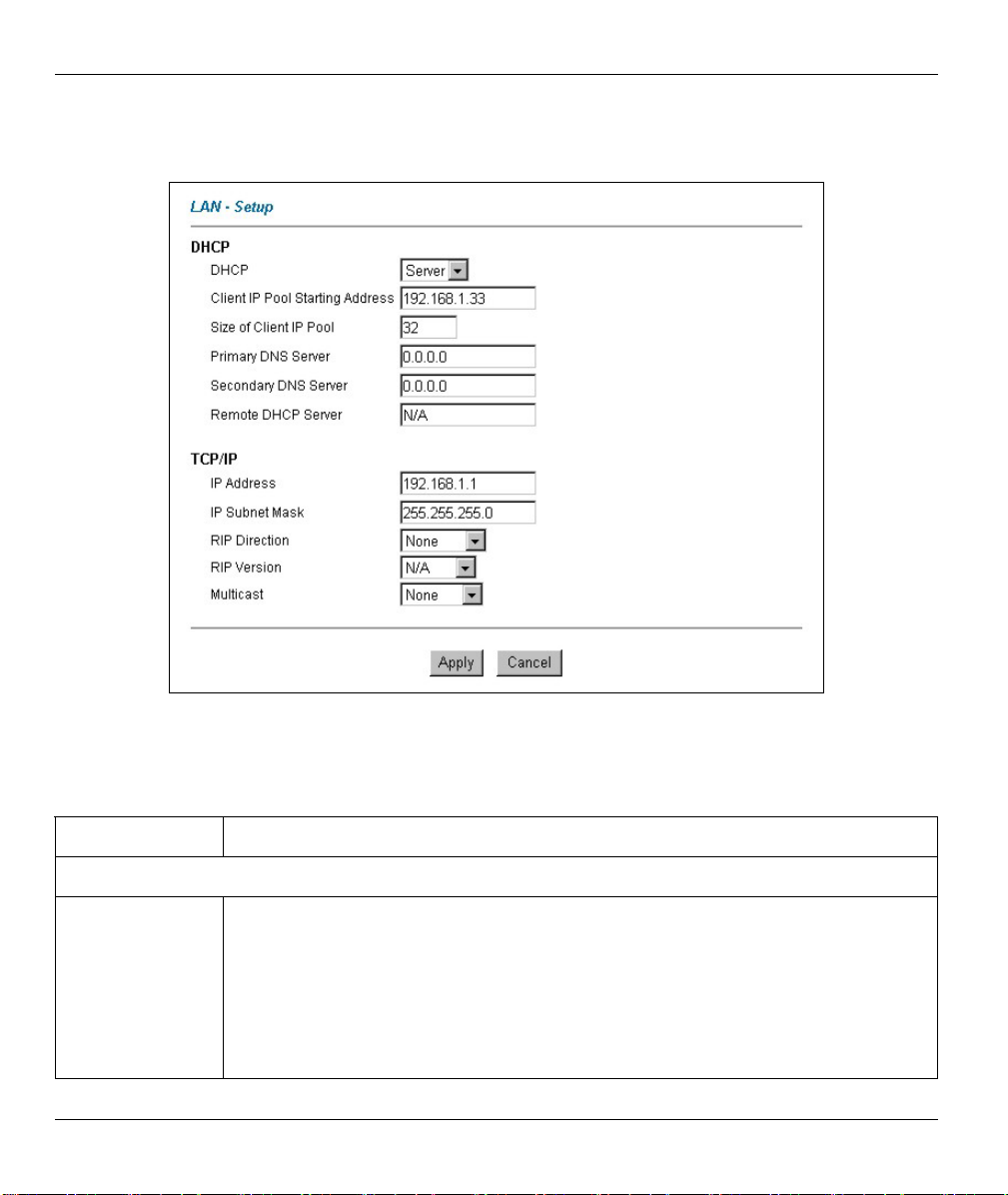
Prestige 660R ADSL 2+ Access Gateway
5.5 Configuring LAN
Click LAN to open the following screen.
Figure 5-2 LAN
The following table describes the fields in this screen.
Table 5-1 LAN
LABEL DESCRIPTION
DHCP
If set to Server, your Prestige can assign IP addresses, an IP default gateway and DNS
servers to Windows 95, Windows NT and other systems that support the DHCP client.
If set to None, the DHCP server will be disabled.
DHCP
If set to Relay, the Prestige acts as a surrogate DHCP server and relays DHCP requests
and responses between the remote server and the clients. Enter the IP address of the
actual, remote DHCP server in the Remote DHCP Server field in this case.
When DHCP is used, the following items need to be set:
5-4 LAN Setup

Prestige 660R ADSL 2+ Access Gateway
Table 5-1 LAN
LABEL DESCRIPTION
Client IP Pool
Starting Address
Size of Client IP
Pool
Primary DNS
Server
Secondary DNS
Server
Remote DHCP
Server
TCP/IP
IP Address
IP Subnet Mask Type the subnet mask assigned to you by your ISP (if given).
RIP Direction
RIP Version
Multicast
This field specifies the first of the contiguous addresses in the IP address pool.
This field specifies the size or count of the IP address pool.
Enter the IP addresses of the DNS servers. The DNS servers are passed to the DHCP
clients along with the IP address and the subnet mask.
As above.
If Relay is selected in the DHCP field above then enter the IP address of the actual
remote DHCP server here.
Enter the IP address of your Prestige in dotted decimal notation, for example,
192.168.1.1 (factory default).
Select the RIP direction from None, Both, In Only and Out Only.
Select the RIP version from RIP-1, RIP-2B and RIP-2M.
IGMP (Internet Group Multicast Protocol) is a network-layer protocol used to establish
membership in a multicast group. The Prestige supports both IGMP version 1 (IGMP-v1)
and IGMP-v2. Select None to disable it.
Apply
Cancel
Click Apply to save your changes back to the Prestige.
Click Cancel to begin configuring this screen afresh.
LAN Setup 5-5


Prestige 660R ADSL 2+ Access Gateway
Chapter 6
WAN Setup
This chapter describes how to configure WAN settings.
6.1 WAN Overview
A WAN (Wide Area Network) is an outside connection to another network or the Internet.
See the Wizard Setup chapter for more information on the fields in the WAN screens.
6.2 Metric
The metric represents the "cost of transmission". A router determines the best route for transmission by
choosing a path with the lowest "cost". RIP routing uses hop count as the measurement of cost, with a
minimum of "1" for directly connected networks. The number must be between "1" and "15"; a number
greater than "15" means the link is down. The smaller the number, the lower the "cost".
The metric sets the priority for the Prestige’s routes to the Internet. If any two of the default routes have the
same metric, the Prestige uses the following pre-defined priorities:
1. Normal route: designated by the ISP (see section 6.5)
2. Traffic-redirect route (see section 6.6)
3. WAN-backup route, also called dial-backup (see section 6.6)
For example, if the normal route has a metric of "1" and the traffic-redirect route has a metric of "2" and dialbackup route has a metric of "3", then the normal route acts as the primary default route. If the normal route
fails to connect to the Internet, the Prestige tries the traffic-redirect route next. In the same manner, the
Prestige uses the dial-backup route if the traffic-redirect route also fails.
If you want the dial-backup route to take first priority over the traffic-redirect route or even the normal route,
all you need to do is set the dial-backup route’s metric to "1" and the others to "2" (or greater).
IP Policy Routing overrides the default routing behavior and takes priority over all
of the routes mentioned above (see the IP Policy Routing chapter).
6.3 PPPoE Encapsulation
The Prestige supports PPPoE (Point-to-Point Protocol over Ethernet). PPPoE is an IETF Draft standard (RFC
2516) specifying how a personal computer (PC) interacts with a broadband modem (DSL, cable, wireless,
etc.) connection. The PPPoE option is for a dial-up connection using PPPoE.
WAN Setup 6-1

Prestige 660R ADSL 2+ Access Gateway
For the service provider, PPPoE offers an access and authentication method that works with existing access
control systems (for example Radius). PPPoE provides a login and authentication method that the existing
Microsoft Dial-Up Networking software can activate, and therefore requires no new learning or procedures
for Windows users.
One of the benefits of PPPoE is the ability to let you access one of multiple network services, a function
known as dynamic service selection. This enables the service provider to easily create and offer new IP
services for individuals.
Operationally, PPPoE saves significant effort for both you and the ISP or carrier, as it requires no specific
configuration of the broadband modem at the customer site.
By implementing PPPoE directly on the Prestige (rather than individual computers), the computers on the
LAN do not need PPPoE software installed, since the Prestige does that part of the task. Furthermore, with
NAT, all of the LANs’ computers will have access.
6.4 Traffic Shaping
Traffic Shaping is an agreement between the carrier and the subscriber to regulate the average rate and
fluctuations of data transmission over an ATM network. This agreement helps eliminate congestion, which is
important for transmission of real time data such as audio and video connections.
Peak Cell Rate (PCR) is the maximum rate at which the sender can send cells. This parameter may be lower
(but not higher) than the maximum line speed. 1 ATM cell is 53 bytes (424 bits), so a maximum speed of
832Kbps gives a maximum PCR of 1962 cells/sec. This rate is not guaranteed because it is dependent on the
line speed.
Sustained Cell Rate (SCR) is the mean cell rate of each bursty traffic source. It specifies the maximum
average rate at which cells can be sent over the virtual connection. SCR may not be greater than the PCR.
Maximum Burst Size (MBS) is the maximum number of cells that can be sent at the PCR. After MBS is
reached, cell rates fall below SCR until cell rate averages to the SCR again. At this time, more cells (up to
the MBS) can be sent at the PCR again.
If the PCR, SCR or MBS is set to the default of “0”, the system will assign a
maximum value that correlates to your upstream line rate.
The following figure illustrates the relationship between PCR, SCR and MBS.
6-2 WAN Setup
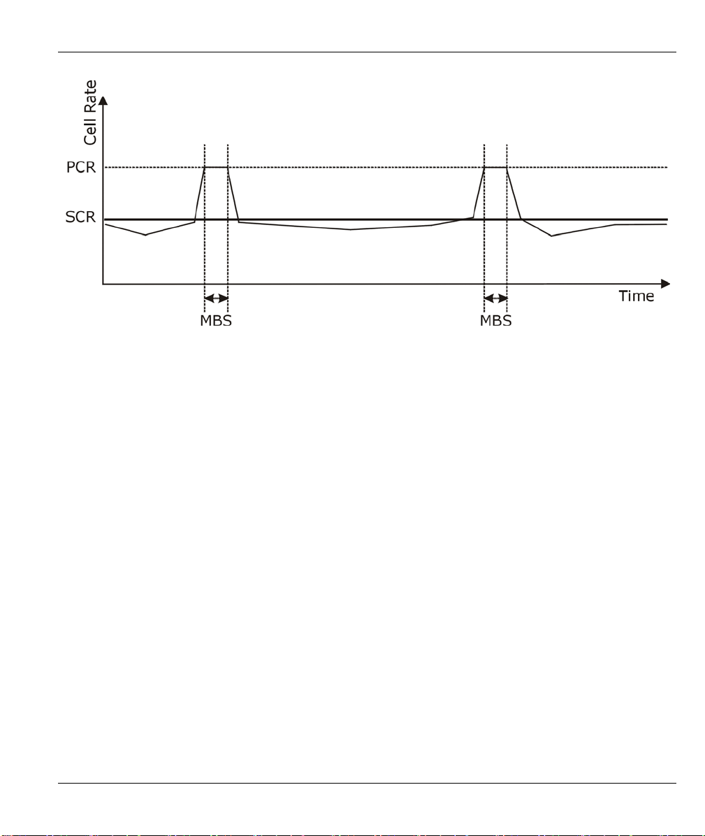
Prestige 660R ADSL 2+ Access Gateway
Figure 6-1 Example of Traffic Shaping
6.5 Configuring WAN Setup
To change your Prestige’s WAN remote node settings, click WAN, WAN Setup. The screen differs by the
encapsulation.
WAN Setup 6-3

Prestige 660R ADSL 2+ Access Gateway
Figure 6-2 WAN Setup
The following table describes the fields in this screen.
6-4 WAN Setup

Prestige 660R ADSL 2+ Access Gateway
Table 6-1 WAN Setup
LABEL DESCRIPTION
Name Enter the name of your Internet Service Provider, e.g., MyISP. This information is for
identification purposes only.
Mode
Encapsulation Select the method of encapsulation used by your ISP from the drop-down list box.
Multiplex Select the method of multiplexing used by your ISP from the drop-down list. Choices
Virtual Circuit ID VPI (Virtual Path Identifier) and VCI (Virtual Channel Identifier) define a virtual circuit.
VPI The valid range for the VPI is 0 to 255. Enter the VPI assigned to you.
VCI The valid range for the VCI is 32 to 65535 (0 to 31 is reserved for local management of
ATM QoS Type
Cell Rate Cell rate configuration often helps eliminate traffic congestion that slows transmission
Select Routing (default) from the drop-down list box if your ISP allows multiple
computers to share an Internet account. Otherwise select Bridge.
Choices vary depending on the mode you select in the Mode field.
If you select Bridge in the Mode field, select either PPPoA or RFC 1483.
If you select Routing in the Mode field, select PPPoA, RFC 1483, ENET ENCAP or
PPPoE.
are VC or LLC.
Refer to the appendix for more information.
ATM traffic). Enter the VCI assigned to you.
Select CBR (Continuous Bit Rate) to specify fixed (always-on) bandwidth for voice or
data traffic. Select UBR (Unspecified Bit Rate) for applications that are non-time
sensitive, such as e-mail. Select VBR (Variable Bit Rate) for bursty traffic and
bandwidth sharing with other applications.
of real time data such as audio and video connections.
Peak Cell Rate Divide the DSL line rate (bps) by 424 (the size of an ATM cell) to find the Peak Cell
Rate (PCR). This is the maximum rate at which the sender can send cells. Type the
PCR here.
Sustain Cell Rate The Sustain Cell Rate (SCR) sets the average cell rate (long-term) that can be
transmitted. Type the SCR, which must be less than the PCR. Note that system default
is 0 cells/sec.
WAN Setup 6-5

Prestige 660R ADSL 2+ Access Gateway
Table 6-1 WAN Setup
LABEL DESCRIPTION
Maximum Burst Size Maximum Burst Size (MBS) refers to the maximum number of cells that can be sent at
the peak rate. Type the MBS, which is less than 65535.
Login Information (PPPoA and PPPoE encapsulation only)
Service Name (PPPoE only) Type the name of your PPPoE service here.
User Name Enter the user name exactly as your ISP assigned. If assigned a name in the form
user@domain
exactly as given.
Password Enter the password associated with the user name above.
where domain identifies a service name, then enter both components
IP Address
Connection
(PPPoA and PPPoE
encapsulation only)
Nailed-Up Connection
Connect on Demand
Max Idle Timeout
PPPoE Pass Through
This option is available if you select Routing in the Mode field.
A static IP address is a fixed IP that your ISP gives you. A dynamic IP address is not
fixed; the ISP assigns you a different one each time you connect to the Internet. The
Single User Account feature can be used with either a dynamic or static IP address.
Select Obtain an IP Address Automatically if you have a dynamic IP address;
otherwise select Static IP Address and type your ISP assigned IP address in the IP
Address field below.
The schedule rule(s) in SMT menu 26 have priority over your Connection settings.
Select Nailed-Up Connection when you want your connection up all the time. The
Prestige will try to bring up the connection automatically if it is disconnected.
Select Connect on Demand when you don't want the connection up all the time and
specify an idle time-out in the Max Idle Timeout field.
Specify an idle time-out in the Max Idle Timeout field when you select Connect on
Demand. The default setting is 0, which means the Internet session will not timeout.
This field is available when you select PPPoE encapsulation.
6-6 WAN Setup

Prestige 660R ADSL 2+ Access Gateway
Table 6-1 WAN Setup
LABEL DESCRIPTION
PPPoE +
PPPoE_Client_PC
(PPPoE
encapsulation only)
Subnet Mask
(ENET ENCAP
encapsulation only)
ENET ENCAP
Gateway
(ENET ENCAP
encapsulation only)
Back
Apply
Cancel
In addition to the Prestige's built-in PPPoE client, you can enable PPPoE pass through
to allow up to ten hosts on the LAN to use PPPoE client software on their computers to
connect to the ISP via the Prestige. Each host can have a separate account and a
public WAN IP address.
PPPoE pass through is an alternative to NAT for application where NAT is not
appropriate.
Disable PPPoE pass through if you do not need to allow hosts on the LAN to use
PPPoE client software on their computers to connect to the ISP.
Enter a subnet mask in dotted decimal notation.
Refer to the Subnetting appendix on how to calculate a subnet mask If you are
implementing subnetting.
You must specify a gateway IP address (supplied by your ISP) when you select ENET
ENCAP in the Encapsulation field
Click Back to return to the previous screen.
Click Apply to save the changes.
Click Cancel to begin configuring this screen afresh.
6.6 Traffic Redirect
Traffic redirect forwards traffic to a backup gateway when the Prestige cannot connect to the Internet. An
example is shown in the figure below.
WAN Setup 6-7

Prestige 660R ADSL 2+ Access Gateway
Figure 6-3 Traffic Redirect Example
The following network topology allows you to avoid triangle route security issues when the backup gateway
is connected to the LAN. Use IP alias to configure the LAN into two or three logical networks with the
Prestige itself as the gateway for each LAN network. Put the protected LAN in one subnet (Subnet 1 in the
following figure) and the backup gateway in another subnet (Subnet 2). Configure filters that allow packets
from the protected LAN (Subnet 1) to the backup gateway (Subnet 2).
Figure 6-4 Traffic Redirect LAN Setup
6.7 Configuring WAN Backup
To change your Prestige’s WAN backup settings, click WAN, then WAN Backup. The screen appears as
shown.
6-8 WAN Setup

Prestige 660R ADSL 2+ Access Gateway
Figure 6-5 WAN Backup
The following table describes the fields in this screen.
WAN Setup 6-9

Prestige 660R ADSL 2+ Access Gateway
Table 6-2 WAN Backup
LABEL DESCRIPTION
Backup Type Select the method that the Prestige uses to check the DSL connection.
Select DSL Link to have the Prestige check if the connection to the DSLAM is
up. Select ICMP to have the Prestige periodically ping the IP addresses
configured in the Check WAN IP Address fields.
Check WAN IP
Address1-3
Configure this field to test your Prestige's WAN accessibility. Type the IP address
of a reliable nearby computer (for example, your ISP's DNS server address).
If you activate either traffic redirect or dial backup, you
must configure at least one IP address here.
When using a WAN backup connection, the Prestige periodically pings the
addresses configured here and uses the other WAN backup connection (if
configured) if there is no response.
Fail Tolerance Type the number of times (2 recommended) that your Prestige may ping the IP
addresses configured in the Check WAN IP Address fields without getting a
response before switching to a WAN backup connection (or a different WAN
backup connection).
Recovery Interval When the Prestige is using a lower priority connection (usually a WAN backup
connection), it periodically checks to whether or not it can use a higher priority
connection.
Type the number of seconds (30 recommended) for the Prestige to wait between
checks. Allow more time if your destination IP address handles lots of traffic.
Timeout Type the number of seconds (3 recommended) for your Prestige to wait for a ping
response from one of the IP addresses in the Check WAN IP Address fields
before timing out the request. The WAN connection is considered "down" after
the Prestige times out the number of times specified in the Fail Tolerance field.
Use a higher value in this field if your network is busy or congested.
Traffic Redirect
Active Select this check box to have the Prestige use traffic redirect if the normal WAN
connection goes down.
If you activate traffic redirect, you must configure at least
one Check WAN IP Address.
6-10 WAN Setup

Prestige 660R ADSL 2+ Access Gateway
Table 6-2 WAN Backup
LABEL DESCRIPTION
Metric This field sets this route's priority among the routes the Prestige uses.
The metric represents the "cost of transmission". A router determines the best
route for transmission by choosing a path with the lowest "cost". RIP routing uses
hop count as the measurement of cost, with a minimum of "1" for directly
connected networks. The number must be between "1" and "15"; a number
greater than "15" means the link is down. The smaller the number, the lower the
"cost".
Backup Gateway Type the IP address of your backup gateway in dotted decimal notation. The
Prestige automatically forwards traffic to this IP address if the Prestige's Internet
connection terminates.
Back
Apply
Cancel
Click Back to return to the previous screen.
Click Apply to save the changes.
Click Cancel to begin configuring this screen afresh.
WAN Setup 6-11


NAT, Dynamic DNS and Time and Date
Part III:
NAT, Dynamic DNS and Time and Date
This part covers NAT (Network Address Translation), dynamic DNS (Domain Name Sever) and
Time and Date setup.
III


Prestige 660R ADSL 2+ Access Gateway
Chapter 7
Network Address Translation (NAT)
Screens
This chapter discusses how to configure NAT on the Prestige.
7.1 NAT Overview
NAT (Network Address Translation - NAT, RFC 1631) is the translation of the IP address of a host in a
packet, for example, the source address of an outgoing packet, used within one network to a different IP
address known within another network.
7.1.1 NAT Definitions
Inside/outside denotes where a host is located relative to the Prestige, for example, the computers of your
subscribers are the inside hosts, while the web servers on the Internet are the outside hosts.
Global/local denotes the IP address of a host in a packet as the packet traverses a router, for example, the
local address refers to the IP address of a host when the packet is in the local network, while the global
address refers to the IP address of the host when the same packet is traveling in the WAN side.
Note that inside/outside refers to the location of a host, while global/local refers to the IP address of a host
used in a packet. Thus, an inside local address (ILA) is the IP address of an inside host in a packet when the
packet is still in the local network, while an inside global address (IGA) is the IP address of the same inside
host when the packet is on the WAN side. The following table summarizes this information.
Table 7-1 NAT Definitions
ITEM DESCRIPTION
Inside This refers to the host on the LAN.
Outside This refers to the host on the WAN.
Local This refers to the packet address (source or destination) as the packet travels on the LAN.
Global This refers to the packet address (source or destination) as the packet travels on the WAN.
NAT 7-1

Prestige 660R ADSL 2+ Access Gateway
NAT never changes the IP address (either local or global) of an outside host.
7.1.2 What NAT Does
In the simplest form, NAT changes the source IP address in a packet received from a subscriber (the inside
local address) to another (the inside global address) before forwarding the packet to the WAN side. When
the response comes back, NAT translates the destination address (the inside global address) back to the inside
local address before forwarding it to the original inside host. Note that the IP address (either local or global)
of an outside host is never changed.
The global IP addresses for the inside hosts can be either static or dynamically assigned by the ISP. In
addition, you can designate servers, for example, a web server and a telnet server, on your local network and
make them accessible to the outside world. If you do not define any servers (for Many-to-One and Many-toMany Overload mapping – see Table 7-2), NAT offers the additional benefit of firewall protection. With no
servers defined, your Prestige filters out all incoming inquiries, thus preventing intruders from probing your
network. For more information on IP address translation, refer to RFC 1631, The IP Network Address
Translator (NAT).
7.1.3 How NAT Works
Each packet has two addresses – a source address and a destination address. For outgoing packets, the ILA
(Inside Local Address) is the source address on the LAN, and the IGA (Inside Global Address) is the source
address on the WAN. For incoming packets, the ILA is the destination address on the LAN, and the IGA is
the destination address on the WAN. NAT maps private (local) IP addresses to globally unique ones required
for communication with hosts on other networks. It replaces the original IP source address (and TCP or UDP
source port numbers for Many-to-One and Many-to-Many Overload NAT mapping) in each packet and then
forwards it to the Internet. The Prestige keeps track of the original addresses and port numbers so incoming
reply packets can have their original values restored. The following figure illustrates this.
Figure 7-1 How NAT Works
7-2 NAT
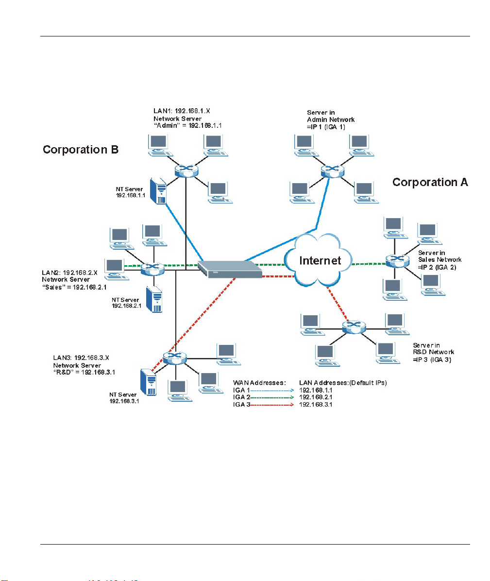
Prestige 660R ADSL 2+ Access Gateway
7.1.4 NAT Application
The following figure illustrates a possible NAT application, where three inside LANs (logical LANs using IP
Alias) behind the Prestige can communicate with three distinct WAN networks. More examples follow at the
end of this chapter.
Figure 7-2 NAT Application With IP Alias
7.1.5 NAT Mapping Types
NAT supports five types of IP/port mapping. They are:
1. One to One: In One-to-One mode, the Prestige maps one local IP address to one global IP address.
2. Many to One: In Many-to-One mode, the Prestige maps multiple local IP addresses to one global IP
address. This is equivalent to SUA (for instance, PAT, port address translation), ZyXEL’s Single User
Account feature that previous ZyXEL routers supported (the SUA Only option in today’s routers).
NAT 7-3

Prestige 660R ADSL 2+ Access Gateway
3. Many to Many Overload: In Many-to-Many Overload mode, the Prestige maps the multiple local IP
addresses to shared global IP addresses.
4. Many-to-Many No Overload:
In Many-to-Many No Overload mode, the Prestige maps each local IP
address to a unique global IP address.
5. Server: This type allows you to specify inside servers of different services behind the NAT to be
accessible to the outside world.
Port numbers do not change for One-to-One and Many-to-Many No Overload NAT
mapping types.
The following table summarizes these types.
Table 7-2 NAT Mapping Types
TYPE IP MAPPING SMT ABBREVIATION
One-to-One ILA1ÅÆ IGA1 1:1
Many-to-One (SUA/PAT) ILA1ÅÆ IGA1
ILA2ÅÆ IGA1
…
Many-to-Many Overload ILA1ÅÆ IGA1
ILA2ÅÆ IGA2
ILA3ÅÆ IGA1
ILA4ÅÆ IGA2
…
Many-to-Many No Overload ILA1ÅÆ IGA1
ILA2ÅÆ IGA2
ILA3ÅÆ IGA3
…
Server Server 1 IPÅÆ IGA1
Server 2 IPÅÆ IGA1
Server 3 IPÅÆ IGA1
M:1
M:M Ov
M:M No OV
Server
7.2 SUA (Single User Account) Versus NAT
SUA (Single User Account) is a ZyNOS implementation of a subset of NAT that supports two types of
mapping, Many-to-One and Server. The Prestige also supports Full Feature NAT to map multiple global
IP addresses to multiple private LAN IP addresses of clients or servers using mapping types as outlined in
Table 7-2.
7-4 NAT
Prestige 660R ADSL 2+ Access Gateway
1. Choose SUA Only if you have just one public WAN IP address for your Prestige.
2. Choose Full Feature if you have multiple public WAN IP addresses for your Prestige.
7.3 SUA Server
A SUA server set is a list of inside (behind NAT on the LAN) servers, for example, web or FTP, that you can
make visible to the outside world even though SUA makes your whole inside network appear as a single
computer to the outside world.
You may enter a single port number or a range of port numbers to be forwarded, and the local IP address of
the desired server. The port number identifies a service; for example, web service is on port 80 and FTP on
port 21. In some cases, such as for unknown services or where one server can support more than one service
(for example both FTP and web service), it might be better to specify a range of port numbers. You can
allocate a server IP address that corresponds to a port or a range of ports.
Many residential broadband ISP accounts do not allow you to run any server processes (such as a Web or
FTP server) from your location. Your ISP may periodically check for servers and may suspend your account
if it discovers any active services at your location. If you are unsure, refer to your ISP.
Default Server IP Address
In addition to the servers for specified services, NAT supports a default server IP address. A default server
receives packets from ports that are not specified in this screen.
If you do not assign an IP address in Server Set 1 (default server), the Prestige
discards all packets received for ports that are not specified here or in the remote
management setup.
7.3.1 Port Forwarding: Services and Port Numbers
The most often used port numbers are shown in the following table. Please refer to RFC 1700 for further
information about port numbers.
Table 7-3 Services and Port Numbers
SERVICES PORT NUMBER
ECHO 7
FTP (File Transfer Protocol) 21
SMTP (Simple Mail Transfer Protocol) 25
DNS (Domain Name System) 53
Finger 79
HTTP (Hyper Text Transfer protocol or WWW, Web) 80
NAT 7-5

Prestige 660R ADSL 2+ Access Gateway
Table 7-3 Services and Port Numbers
SERVICES PORT NUMBER
POP3 (Post Office Protocol) 110
NNTP (Network News Transport Protocol) 119
SNMP (Simple Network Management Protocol) 161
SNMP trap 162
PPTP (Point-to-Point Tunneling Protocol) 1723
7.3.2 Configuring Servers Behind SUA (Example)
Let's say you want to assign ports 21-25 to one FTP, Telnet and SMTP server (A in the example), port 80 to
another (B in the example) and assign a default server IP address of 192.168.1.35 to a third (C in the
example). You assign the LAN IP addresses and the ISP assigns the WAN IP address. The NAT network
appears as a single host on the Internet.
IP address assigned
by ISP.
Figure 7-3 Multiple Servers Behind NAT Example
7.4 Selecting the NAT Mode
You must create a firewall rule in addition to setting up SUA/NAT, to allow traffic
from the WAN to be forwarded through the Prestige.
Click NAT to open the following screen.
7-6 NAT

Prestige 660R ADSL 2+ Access Gateway
Figure 7-4 NAT Mode
The following table describes the labels in this screen.
Table 7-4 NAT Mode
LABEL DESCRIPTION
None Select this radio button to disable NAT.
SUA Only
Edit Details
Full Feature Select this radio button if you have multiple public WAN IP addresses for your Prestige.
Edit Details
Apply
Select this radio button if you have just one public WAN IP address for your Prestige. The
Prestige uses Address Mapping Set 1 in the NAT - Edit SUA/NAT Server Set screen.
Click this link to go to the NAT - Edit SUA/NAT Server Set screen.
Click this link to go to the NAT - Address Mapping Rules screen.
Click Apply to save your configuration.
7.5 Configuring SUA Server
If you do not assign an IP address in Server Set 1 (default server), the Prestige
discards all packets received for ports that are not specified here or in the remote
management setup.
Click NAT, select SUA Only and click Edit Details to open the following screen.
Refer to Table 7-3 for port numbers commonly used for particular services.
NAT 7-7

Prestige 660R ADSL 2+ Access Gateway
Figure 7-5 Edit SUA/NAT Server Set
The following table describes the fields in this screen.
Table 7-5 Edit SUA/NAT Server Set
LABEL DESCRIPTION
Start Port No. Enter a port number in this field.
To forward only one port, enter the port number again in the End Port No. field.
To forward a series of ports, enter the start port number here and the end port number
in the End Port No. field.
7-8 NAT

Prestige 660R ADSL 2+ Access Gateway
Table 7-5 Edit SUA/NAT Server Set
LABEL DESCRIPTION
End Port No. Enter a port number in this field.
To forward only one port, enter the port number again in the Start Port No. field above
and then enter it again in this field.
To forward a series of ports, enter the last port number in a series that begins with the
port number in the Start Port No. field above.
Server IP
Address
Save
Cancel
Enter your server IP address in this field.
Click Save to save your changes back to the Prestige.
Click Cancel to return to the previous configuration.
7.6 Configuring Address Mapping
Ordering your rules is important because the Prestige applies the rules in the order that you specify. When a
rule matches the current packet, the Prestige takes the corresponding action and the remaining rules are
ignored. If there are any empty rules before your new configured rule, your configured rule will be pushed up
by that number of empty rules. For example, if you have already configured rules 1 to 6 in your current set
and now you configure rule number 9. In the set summary screen, the new rule will be rule 7, not 9. Now if
you delete rule 4, rules 5 to 7 will be pushed up by 1 rule, so old rules 5, 6 and 7 become new rules 4, 5 and
6.
To change your Prestige’s address mapping settings, click NAT, Select Full Feature and click Edit Details
to open the following screen.
NAT 7-9

Prestige 660R ADSL 2+ Access Gateway
Figure 7-6 Address Mapping Rules
The following table describes the fields in this screen.
Table 7-6 Address Mapping Rules
LABEL DESCRIPTION
Local Start IP
Local End IP This is the end Inside Local IP Address (ILA). If the rule is for all local IP addresses, then
Global Start IP This is the starting Inside Global IP Address (IGA). Enter 0.0.0.0 here if you have a
Global End IP
This is the starting Inside Local IP Address (ILA). Local IP addresses are N/A for Server
port mapping.
this field displays 0.0.0.0 as the Local Start IP address and 255.255.255.255 as the
Local End IP address. This field is N/A for One-to-one and Server mapping types.
dynamic IP address from your ISP. You can only do this for Many-to-One and Server
mapping types.
This is the ending Inside Global IP Address (IGA). This field is N/A for One-to-one,
Many-to-One and Server mapping types.
7-10 NAT

Prestige 660R ADSL 2+ Access Gateway
Table 7-6 Address Mapping Rules
LABEL DESCRIPTION
Type
Back
1-1: One-to-one mode maps one local IP address to one global IP address. Note that
port numbers do not change for the One-to-one NAT mapping type.
M-1: Many-to-One mode maps multiple local IP addresses to one global IP address. This
is equivalent to SUA (i.e., PAT, port address translation), ZyXEL's Single User Account
feature that previous ZyXEL routers supported only.
M-M Ov (Overload): Many-to-Many Overload mode maps multiple local IP addresses to
shared global IP addresses.
MM No (No Overload): Many-to-Many No Overload mode maps each local IP address to
unique global IP addresses.
Server: This type allows you to specify inside servers of different services behind the
NAT to be accessible to the outside world.
Click Back to return to the NAT Mode screen.
7.7 Editing an Address Mapping Rule
To edit an address mapping rule, click the rule’s link in the NAT Address Mapping Rules screen to display
the screen shown next.
Figure 7-7 Address Mapping Rule Edit
The following table describes the fields in this screen.
NAT 7-11

Prestige 660R ADSL 2+ Access Gateway
Table 7-7 Address Mapping Rule Edit
LABEL DESCRIPTION
Type Choose the port mapping type from one of the following.
1. One-to-One: One-to-One mode maps one local IP address to one global IP
address. Note that port numbers do not change for One-to-one NAT mapping type.
2. Many-to-One: Many-to-One mode maps multiple local IP addresses to one global
IP address. This is equivalent to SUA (i.e., PAT, port address translation), ZyXEL's
Single User Account feature that previous ZyXEL routers supported only.
3. Many-to-Many Overload: Many-to-Many Overload mode maps multiple local IP
addresses to shared global IP addresses.
4. Many-to-Many No Overload: Many-to-Many No Overload mode maps each local
IP address to unique global IP addresses.
5. Server: This type allows you to specify inside servers of different services behind
the NAT to be accessible to the outside world.
Local Start IP
Local End IP This is the end local IP address (ILA). If your rule is for all local IP addresses, then
Global Start IP This is the starting global IP address (IGA). Enter 0.0.0.0 here if you have a dynamic
Global End IP
Server Mapping
Set
Edit Details
Apply
Cancel
Delete
This is the starting local IP address (ILA). Local IP addresses are N/A for Server port
mapping.
enter 0.0.0.0 as the Local Start IP address and 255.255.255.255 as the Local End
IP address.
This field is N/A for One-to-One and Server mapping types.
IP address from your ISP.
This is the ending global IP address (IGA). This field is N/A for One-to-One, Many-
to-One and Server mapping types.
Only available when Type is set to Server.
Select a number from the drop-down menu to choose a server set from the NAT -
Address Mapping Rules screen.
Click this link to go to the NAT - Edit SUA/NAT Server Set screen to edit a server
set that you have selected in the Server Mapping Set field.
Click Apply to save your changes back to the Prestige.
Click Cancel to return to the previously saved settings.
Click Delete to exit this screen without saving.
7-12 NAT

Prestige 660R ADSL 2+ Access Gateway
Chapter 8
Dynamic DNS Setup
This chapter discusses how to configure your Prestige to use Dynamic DNS.
8.1 Dynamic DNS
Dynamic DNS allows you to update your current dynamic IP address with one or many dynamic DNS
services so that anyone can contact you (in NetMeeting, CU-SeeMe, etc.). You can also access your FTP
server or Web site on your own computer using a domain name (for instance myhost.dhs.org, where myhost
is a name of your choice) that will never change instead of using an IP address that changes each time you
reconnect. Your friends or relatives will always be able to call you even if they don't know your IP address.
First of all, you need to have registered a dynamic DNS account with www.dyndns.org. This is for people
with a dynamic IP from their ISP or DHCP server that would still like to have a domain name. The Dynamic
DNS service provider will give you a password or key.
8.1.1 DYNDNS Wildcard
Enabling the wildcard feature for your host causes *.yourhost.dyndns.org to be aliased to the same IP address
as yourhost.dyndns.org. This feature is useful if you want to be able to use, for example,
www.yourhost.dyndns.org and still reach your hostname.
If you have a private WAN IP address, then you cannot use Dynamic DNS.
8.2 Configuring Dynamic DNS
To change your Prestige’s DDNS, click Dynamic DNS. The screen appears as shown.
Dynamic DNS Setup 8-1

Prestige 660R ADSL 2+ Access Gateway
Figure 8-1 DDNS
The following table describes the fields in this screen.
Table 8-1 DDNS
LABEL DESCRIPTION
Active Select this check box to use dynamic DNS.
Service Provider This is the name of your Dynamic DNS service provider.
Host Names Type the domain name assigned to your Prestige by your Dynamic DNS provider.
E-mail Address Type your e-mail address.
User Type your user name.
Password Type the password assigned to you.
Enable Wildcard Select the check box to enable DYNDNS Wildcard.
Apply
Cancel
Click Apply to save your changes back to the Prestige.
Click Cancel to begin configuring this screen afresh.
8-2 Dynamic DNS Setup

Prestige 660R ADSL 2+ Access Gateway
Chapter 9
Time and Date
This screen is not available on all models. Use this screen to configure the Prestige’s time and date
settings.
9.1 Configuring Time and Date
To change your Prestige’s time and date, click Time And Date. The screen appears as shown. Use this
screen to configure the Prestige’s time based on your local time zone.
Figure 9-1 Time and Date
Time and Date 9-1

Prestige 660R ADSL 2+ Access Gateway
The following table describes the fields in this screen.
Table 9-1 Time and Date
LABEL DESCRIPTION
Time Server
Use Protocol when
Bootup
IP Address or URL Enter the IP address or URL of your time server. Check with your ISP/network
Time and Date Choose the time zone of your location. This will set the time difference between your
Daylight Savings Select this option if you use daylight savings time. Daylight saving is a period from
Start Date Enter the month and day that your daylight-savings time starts on if you selected
End Date Enter the month and day that your daylight-savings time ends on if you selected
Synchronize
system clock with
Time Server now.
Date
Current Date This field displays the date of your Prestige.
Select the time service protocol that your time server sends when you turn on the
Prestige. Not all time servers support all protocols, so you may have to check with
your ISP/network administrator or use trial and error to find a protocol that works.
The main difference between them is the format.
Daytime (RFC 867) format is day/month/year/time zone of the server.
Time (RFC 868) format displays a 4-byte integer giving the total number of seconds
since 1970/1/1 at 0:0:0.
The default, NTP (RFC 1305), is similar to Time (RFC 868).
Select None to enter the time and date manually.
administrator if you are unsure of this information (the default is tick.stdtime.gov.tw).
time zone and Greenwich Mean Time (GMT).
late spring to early fall when many countries set their clocks ahead of normal local
time by one hour to give more daytime light in the evening.
Daylight Savings.
Daylight Savings.
Select this option to have your Prestige use the time server (that you configured
above) to set its internal system clock.
Please wait for up to 60 seconds while the Prestige locates the time server. If the
Prestige cannot find the time server, please check the time server protocol and its IP
address. If the IP address was entered correctly, try pinging it for example to test the
connection.
Each time you reload this page, the Prestige synchronizes the time with the time
server.
9-2 Time and Date

LABEL DESCRIPTION
New Date (yyyy-
Time
Current Time This field displays the time of your Prestige.
Apply
Cancel
Prestige 660R ADSL 2+ Access Gateway
Table 9-1 Time and Date
This field displays the last updated date from the time server.
mm-dd)
New Time This field displays the last updated time from the time server.
When you select None in the Use Protocol when Bootup field, enter the new date
in this field and then click Apply.
Each time you reload this page, the Prestige synchronizes the time with the time
server.
When you select None in the Use Protocol when Bootup field, enter the new time
in this field and then click Apply.
Click Apply to save your changes back to the Prestige.
Click Cancel to begin configuring this screen afresh.
Time and Date 9-3


Remote Management and UPnP
Part IV:
Remote Management and UPnP
This part contains information on how to configure the Prestige for remote management and setting
up Universal Plug and Play (UPnP).
IV


Prestige 660R ADSL 2+ Access Gateway
Chapter 10
Remote Management Configuration
This chapter provides information on configuring remote management.
10.1 Remote Management Overview
Remote management allows you to determine which services/protocols can access which Prestige interface
(if any) from which computers.
You may manage your Prestige from a remote location via:
Internet (WAN only) ALL (LAN and WAN)
LAN only, Neither (Disable).
To disable remote management of a service, select Disable in the corresponding Server Access field.
You may only have one remote management session running at a time. The Prestige automatically
disconnects a remote management session of lower priority when another remote management session of
higher priority starts. The priorities for the different types of remote management sessions are as follows.
1. Telnet
2. HTTP
10.1.1 Remote Management Limitations
Remote management over LAN or WAN will not work when:
1. A filter in SMT menu 3.1 (LAN) or in menu 11.5 (WAN) is applied to block a Telnet, FTP or Web
service.
2. You have disabled that service in one of the remote management screens.
3. The IP address in the Secured Client IP field does not match the client IP address. If it does not
match, the Prestige will disconnect the session immediately.
4. There is already another remote management session with an equal or higher priority running. You
may only have one remote management session running at one time.
Remote Management Configuration 10-1

Prestige 660R ADSL 2+ Access Gateway
10.1.2 Remote Management and NAT
When NAT is enabled:
Use the Prestige’s WAN IP address when configuring from the WAN.
Use the Prestige’s LAN IP address when configuring from the LAN.
10.1.3 System Timeout
There is a default system management idle timeout of five minutes (three hundred seconds). The Prestige
automatically logs you out if the management session remains idle for longer than this timeout period. The
management session does not time out when a statistics screen is polling.
10.2 Telnet
You can configure your Prestige for remote Telnet access as shown next.
Figure 10-1 Telnet Configuration on a TCP/IP Network
10.3 FTP
You can upload and download Prestige firmware and configuration files using FTP. To use this feature, your
computer must have an FTP client.
10.4 Web
You can use the Prestige’s embedded web configurator for configuration and file management. See the
online help for details.
10-2 Remote Management Configuration

Prestige 660R ADSL 2+ Access Gateway
10.5 Configuring Remote Management
Click Remote Management to open the following screen.
Figure 10-2 Remote Management
The following table describes the fields in this screen.
Table 10-1 Remote Management
LABEL DESCRIPTION
Server Type Each of these labels denotes a service that you may use to remotely manage the Prestige.
Access Status
Port
Secured Client
IP
Apply
Cancel
Select the access interface. Choices are All, LAN Only, WAN Only and Disable.
This field shows the port number for the remote management service. You may change the
port number for a service in this field, but you must use the same port number to use that
service for remote management.
The default 0.0.0.0 allows any client to use this service to remotely manage the Prestige.
Type an IP address to restrict access to a client with a matching IP address.
Click Apply to save your settings back to the Prestige.
Click Cancel to begin configuring this screen afresh.
Remote Management Configuration 10-3


Prestige 660R ADSL 2+ Access Gateway
Chapter 11
Universal Plug-and-Play (UPnP)
This chapter introduces the UPnP feature in the web configurator.
11.1 Introducing Universal Plug and Play
Universal Plug and Play (UPnP) is a distributed, open networking standard that uses TCP/IP for simple peerto-peer network connectivity between devices. A UPnP device can dynamically join a network, obtain an IP
address, convey its capabilities and learn about other devices on the network. In turn, a device can leave a
network smoothly and automatically when it is no longer in use.
11.1.1 How do I know if I'm using UPnP?
UPnP hardware is identified as an icon in the Network Connections folder (Windows XP). Each UPnP
compatible device installed on your network will appear as a separate icon. Selecting the icon of a UPnP
device will allow you to access the information and properties of that device.
11.1.2 NAT Traversal
UPnP NAT traversal automates the process of allowing an application to operate through NAT. UPnP
network devices can automatically configure network addressing, announce their presence in the network to
other UPnP devices and enable exchange of simple product and service descriptions. NAT traversal allows
the following:
Dynamic port mapping
Learning public IP addresses
Assigning lease times to mappings
Windows Messenger is an example of an application that supports NAT traversal and UPnP.
See the Network Address Translation (NAT) chapter for further information about NAT.
11.1.3 Cautions with UPnP
The automated nature of NAT traversal applications in establishing their own services may present network
security issues. Network information and configuration may also be obtained and modified by users in some
network environments.
UPnP 11-1

Prestige 660R ADSL 2+ Access Gateway
All UPnP-enabled devices may communicate freely with each other without additional configuration. Disable
UPnP if this is not your intention.
11.2 UPnP and ZyXEL
ZyXEL has achieved UPnP certification from the Universal Plug and Play Forum Creates UPnP™
Implementers Corp. (UIC). ZyXEL's UPnP implementation supports IGD 1.0 (Internet Gateway Device). At
the time of writing ZyXEL's UPnP implementation supports Windows Messenger 4.6 and 4.7 while
Windows Messenger 5.0 and Xbox are still being tested.
UPnP broadcasts are only allowed on the LAN.
See later sections for examples of installing UPnP in Windows XP and Windows Me as well as an example
of using UPnP in Windows.
11.2.1 Configuring UPnP
From the Site Map in the main menu, click UPnP under Advanced Setup to display the screen shown next.
Figure 11-1 Configuring UPnP
The following table describes the fields in this screen.
Table 11-1 Configuring UPnP
LABEL DESCRIPTION
Enable the Universal Plug
and Play (UPnP) Service
Select this checkbox to activate UPnP. Be aware that anyone could use a
UPnP application to open the web configurator's login screen without entering
the Prestige's IP address (although you must still enter the password to
access the web configurator).
11-2 UPnP
 Loading...