


 Loading...
RGS Series
Rugged Switch Series
Version 1
Edition 2, 11/2018
Hardware and Web User’s Guide
Default Login Details
LAN IP Address |
http://192.168.1.1 |
|
|
User Name |
admin |
|
|
Password |
1234 |
|
|
Copyright © 2018 Zyxel Communications Corporation
1

IMPORTANT!
READ CAREFULLY BEFORE USE.
KEEP THIS GUIDE FOR FUTURE REFERENCE.
This is a User’s Guide for a series of products. Not all products support all firmware features. Screenshots and graphics in this book may differ slightly from your product due to differences in your product firmware or your computer operating system. Every effort has been made to ensure that the information in this manual is accurate.
Related Documentation
• CLI Reference Guide
The CLI Reference Guide explains how to use the Command-Line Interface (CLI) to configure the Switch.
Note: It is recommended you use the Web Configurator to configure the Switch.
• Web Configurator Online Help
Click the help icon in any screen for help in configuring that screen and supplementary information.
• More Information
Go to support.Zyxel.com to find other information on the Switch.
2

[CONTENTS]
1. |
Preface............................................................................................................................. |
|
8 |
1.1 |
Scope............................................................................................................................... |
|
8 |
1.2 |
Audience .......................................................................................................................... |
8 |
|
1.3 |
Safety Instructions............................................................................................................ |
8 |
|
1.4 |
Documentation Conventions ............................................................................................ |
8 |
|
2. |
Overview ........................................................................................................................ |
10 |
|
2.1 |
Faceplate ....................................................................................................................... |
10 |
|
2.2 |
Front Panel Introduction .................................................................................................. |
11 |
|
2.3 |
Top Panel Introduction.................................................................................................... |
12 |
|
3. |
Quick Installation............................................................................................................ |
14 |
|
3.1 |
Mounting the RGS Series (DIN-Rail) .............................................................................. |
14 |
|
3.2 |
Mounting the RGS Series (Wall mount) .......................................................................... |
15 |
|
3.3 |
Ground Connections ...................................................................................................... |
16 |
|
3.4 |
Connecting the Ethernet Interface (RJ45 Ethernet) ........................................................ |
17 |
|
3.5 |
Connecting the Ethernet Interface (Fiber)....................................................................... |
18 |
|
3.6 |
Power Connection .......................................................................................................... |
19 |
|
3.7 |
Console Connection ....................................................................................................... |
20 |
|
3.8 |
System Reset................................................................................................................. |
21 |
|
3.9 |
Web Interface Initialization (Optional) ............................................................................. |
21 |
|
3.10 |
CLI Initialization and Configuration (Optional)................................................................. |
23 |
|
3.11 |
Monitoring the Ethernet Interface ................................................................................... |
24 |
|
3.12 |
Upgrade Software .......................................................................................................... |
24 |
|
3.13 |
Reset to Default and Save Configure ............................................................................. |
25 |
|
3.14 |
DIP Switch Setting for RGS100-5P ................................................................................ |
28 |
|
3.15 |
LED Status Indications ................................................................................................... |
28 |
|
4. |
Introduction .................................................................................................................... |
30 |
|
4.1 |
System Description ........................................................................................................ |
30 |
|
4.2 |
Using the Web Interface ................................................................................................. |
30 |
|
|
4.2.1 |
Web Browser Support ....................................................................................... |
30 |
|
4.2.2 |
Navigation ......................................................................................................... |
31 |
|
4.2.3 |
Title Bar Icons ................................................................................................... |
31 |
|
4.2.4 |
Ending a Session .............................................................................................. |
31 |
4.3 |
Using the Online Help .................................................................................................... |
32 |
|
5. |
Using the Web................................................................................................................ |
33 |
|
5.1 |
Login .............................................................................................................................. |
|
33 |
5.2 |
Tree View ....................................................................................................................... |
33 |
|
|
5.2.1 |
Configuration Menu ........................................................................................... |
34 |
|
5.2.2 |
Monitor Menu .................................................................................................... |
35 |
|
5.2.3 |
Diagnostics Menu .............................................................................................. |
36 |
|
5.2.4 |
Maintenance Menu ............................................................................................ |
36 |
5.3 |
Configuration.................................................................................................................. |
37 |
|
|
5.3.1 |
System Information ........................................................................................... |
37 |
|
5.3.2 |
System IP.......................................................................................................... |
38 |
|
5.3.3 |
System NTP ...................................................................................................... |
40 |
|
5.3.4 |
System Time ..................................................................................................... |
40 |
|
5.3.5 |
System Log ....................................................................................................... |
43 |
3

5.3.6 |
System Alarm Profile ......................................................................................... |
43 |
5.3.7 |
EEE – Port Power Savings ................................................................................ |
45 |
5.3.8 |
Port ................................................................................................................... |
47 |
5.3.9 |
DHCP Snooping ................................................................................................ |
48 |
5.3.10 |
DHCP Relay ...................................................................................................... |
49 |
5.3.11 |
Security – Switch Users..................................................................................... |
51 |
5.3.12 |
Privilege Level ................................................................................................... |
52 |
5.3.13 |
Authentication Method....................................................................................... |
54 |
5.3.14 |
SSH................................................................................................................... |
55 |
5.3.15 |
HTTPS .............................................................................................................. |
56 |
5.3.16 |
Access Management ......................................................................................... |
57 |
5.3.17 |
SNMP System Configuration ............................................................................. |
58 |
5.3.18 |
SNMP Trap Configuration.................................................................................. |
60 |
5.3.19 |
SNMP Communities .......................................................................................... |
63 |
5.3.20 |
SNMP Users...................................................................................................... |
64 |
5.3.21 |
SNMP Groups ................................................................................................... |
66 |
5.3.22 |
SNMP Views ..................................................................................................... |
67 |
5.3.23 |
SNMP Access.................................................................................................... |
68 |
5.3.25 |
RMON Statistics ................................................................................................ |
69 |
5.3.26 |
RMON History ................................................................................................... |
70 |
5.3.27 |
RMON Alarm ..................................................................................................... |
71 |
5.3.28 |
RMON Event ..................................................................................................... |
73 |
5.3.29 |
Network – Limit Control ..................................................................................... |
74 |
5.3.30 |
ACL – ACL Port ................................................................................................. |
77 |
5.3.31 |
ACL Rate Limiters ............................................................................................. |
78 |
5.3.32 |
Access Control List............................................................................................ |
80 |
5.3.33 |
IP Source Guard – Configuration....................................................................... |
87 |
5.3.34 |
IP Source Guard Static Table............................................................................. |
89 |
5.3.35 |
ARP Inspection – Port Configuration ................................................................. |
90 |
5.3.36 |
VLAN Configuration........................................................................................... |
92 |
5.3.37 |
Static Table........................................................................................................ |
93 |
5.3.38 |
Dynamic Table................................................................................................... |
94 |
5.3.39 |
AAA – RADIUS.................................................................................................. |
95 |
5.3.40 |
TACACS+.......................................................................................................... |
97 |
5.3.41 |
Aggregation – Static Aggregation ...................................................................... |
99 |
5.3.42 |
LACP Aggregation ........................................................................................... |
101 |
5.3.43 |
Loop Protection ............................................................................................... |
103 |
5.3.44 |
Spanning Tree – Bridge Settings ..................................................................... |
105 |
5.3.45 |
MSTI Mapping ................................................................................................. |
107 |
5.3.46 |
MSTI Priorities................................................................................................. |
109 |
5.3.47 |
CIST Ports........................................................................................................ |
110 |
5.3.48 |
MSTI Ports ....................................................................................................... |
112 |
5.3.49 |
IPMC Profile – Profile Table.............................................................................. |
115 |
5.3.50 |
Address Entry................................................................................................... |
116 |
5.3.51 |
MVR ................................................................................................................. |
117 |
5.3.52 |
IPMC – IGMP Snooping Basic Configuration.................................................... |
119 |
5.3.53 |
VLAN Configuration......................................................................................... |
121 |
5.3.54 |
Port Filtering Profile ......................................................................................... |
123 |
5.3.55 |
MLD Snooping – Basic Configuration .............................................................. |
124 |
5.3.56 |
VLAN Configuration......................................................................................... |
126 |
4

5.3.57 |
Port Filtering Profile ......................................................................................... |
128 |
5.3.58 |
LLDP – LLDP Configuration ............................................................................ |
129 |
5.3.59 |
LLDP - MED ...................................................................................................... |
131 |
5.3.60 |
PoE ................................................................................................................. |
135 |
5.3.61 |
PoE Scheduler ................................................................................................ |
137 |
5.3.62 |
Power Reset .................................................................................................... |
138 |
5.3.63 |
MAC Table ....................................................................................................... |
139 |
5.3.64 |
VLANs ............................................................................................................. |
140 |
5.3.65 |
Voice VLAN – Configuration ............................................................................ |
143 |
5.3.66 |
Voice VLAN OUI .............................................................................................. |
145 |
5.3.67 |
QoS – Port Classification ................................................................................. |
146 |
5.3.68 |
Port Policing .................................................................................................... |
149 |
5.3.69 |
Port Scheduler ................................................................................................. |
150 |
5.3.70 |
Port Shaping ................................................................................................... |
151 |
5.3.71 |
Port Tag Remarking ......................................................................................... |
152 |
5.3.72 |
Port DSCP ....................................................................................................... |
153 |
5.3.73 |
DSCP - Based QoS ........................................................................................... |
155 |
5.3.74 |
DSCP Translation ............................................................................................ |
157 |
5.3.75 |
DSCP Classification ........................................................................................ |
159 |
5.3.76 |
QoS Control List .............................................................................................. |
160 |
5.3.77 |
Storm Control .................................................................................................. |
163 |
5.3.78 |
Mirror ............................................................................................................... |
164 |
5.3.79 |
GVRP – Global Config ..................................................................................... |
166 |
5.3.80 |
Port Config ...................................................................................................... |
167 |
5.3.81 |
RingV2 ............................................................................................................ |
168 |
5.3.82 |
DDMI ............................................................................................................... |
170 |
5.4 Monitor |
......................................................................................................................... |
171 |
5.4.1 |
System – System Information .......................................................................... |
171 |
5.4.2 ........................................................................................................ |
CPU Load |
172 |
5.4.3 .......................................................................................................... |
IP Status |
173 |
5.4.4 ..................................................................................................... |
System Log |
174 |
5.4.5 ....................................................................................... |
System Detailed Log |
175 |
5.4.6 .................................................................................................. |
System Alarm |
175 |
5.4.7 ................................................................................ |
EEE – Port Power Saving |
176 |
5.4.8 ............................................................................................ |
Ports – Port State |
177 |
5.4.9 ............................................................................................... |
Traffic Overview |
178 |
5.4.10 .................................................................................................. |
QoS Statistics |
179 |
5.4.11 ...................................................................................................... |
QCL Status |
180 |
5.4.12 ............................................................................................ |
Detailed Statistics |
181 |
5.4.13 ..................................................................................... |
DHCP Snooping Table |
183 |
5.4.14 ..................................................................................... |
DHCP Relay Statistics |
184 |
5.4.15 ................................................................................. |
DHCP Detailed Statistics |
185 |
5.4.16 ....................................................... |
Security – Access Management Statistics |
186 |
5.4.17 ....................................................................... |
Network – Port Security Switch |
187 |
5.4.18 ................................................................................................................. |
Port |
189 |
5.4.19 ...................................................................................................... |
ACL Status |
190 |
5.4.20 ................................................................................................ |
ARP Inspection |
191 |
5.4.21 .............................................................................................. |
IP Source Guard |
192 |
5.4.22 ................................................................................ |
AAA – RADIUS Overview |
193 |
5.4.23 ............................................................................................... |
RADIUS Details |
194 |
5

|
5.4.24 |
Switch – RMON Statistics................................................................................ |
195 |
|
5.4.25 |
History ............................................................................................................. |
197 |
|
5.4.26 |
Alarm............................................................................................................... |
198 |
|
5.4.27 |
Event ............................................................................................................... |
199 |
|
5.4.28 |
LACP System Status ....................................................................................... |
200 |
|
5.4.29 |
Port Status ...................................................................................................... |
201 |
|
5.4.30 |
Port Statistics .................................................................................................. |
202 |
|
5.4.31 |
Loop Protection ............................................................................................... |
203 |
|
5.4.32 |
Spanning Tree – Bridge Status........................................................................ |
204 |
|
5.4.33 |
Port Status ...................................................................................................... |
205 |
|
5.4.34 |
Port Statistics .................................................................................................. |
206 |
|
5.4.35 |
MVR – MVR Statistics ..................................................................................... |
207 |
|
5.4.36 |
MVR Channel Groups ..................................................................................... |
208 |
|
5.4.37 |
MVR SFM Information ..................................................................................... |
209 |
|
5.4.38 |
IPMC – IGMP Snooping Status ....................................................................... |
210 |
|
5.4.39 |
Groups Information........................................................................................... |
211 |
|
5.4.40 |
IPv4 SFM Information...................................................................................... |
212 |
|
5.4.41 |
MLD Snooping Status...................................................................................... |
213 |
|
5.4.42 |
Groups Information.......................................................................................... |
214 |
|
5.4.43 |
IPv6 SFM Information...................................................................................... |
215 |
|
5.4.44 |
LLDP Neighbors .............................................................................................. |
216 |
|
5.4.45 |
LLDP-MED Neighbors ..................................................................................... |
217 |
|
5.4.46 |
PoE Status ...................................................................................................... |
221 |
|
5.4.47 |
EEE................................................................................................................. |
223 |
|
5.4.48 |
Port Statistics .................................................................................................. |
225 |
|
5.4.49 |
MAC Table....................................................................................................... |
226 |
|
5.4.50 |
VLANs – VLANs Membership.......................................................................... |
228 |
|
5.4.51 |
VLANs Ports.................................................................................................... |
229 |
|
5.4.52 |
RingV2 ............................................................................................................ |
231 |
|
5.4.53 |
DDMI Overview ............................................................................................... |
231 |
|
5.4.54 |
DDMI Detailed ................................................................................................. |
232 |
5.5 |
Diagnostics .................................................................................................................. |
233 |
|
|
5.5.1 |
Ping................................................................................................................. |
233 |
|
5.5.2 |
Ping6............................................................................................................... |
235 |
|
5.5.3 |
VeriPHY........................................................................................................... |
237 |
5.6 |
Maintenance................................................................................................................. |
239 |
|
|
5.6.1 |
Restart Device................................................................................................. |
239 |
|
5.6.2 |
Factory Default ................................................................................................ |
240 |
|
5.6.3 |
Software Upload.............................................................................................. |
241 |
|
5.6.4 |
Image Select ................................................................................................... |
242 |
|
5.6.5 |
Configuration – Save startup-config................................................................. |
244 |
|
5.6.6 |
Download ........................................................................................................ |
244 |
|
5.6.7 |
Upload............................................................................................................. |
245 |
|
5.6.8 |
Activate ........................................................................................................... |
246 |
|
5.6.9 |
Delete.............................................................................................................. |
246 |
6. |
Legal Information ......................................................................................................... |
247 |
|
7. |
Customer Support ........................................................................................................ |
252 |
|
6

Preface
Scope
Audience
Safety Instructions
Documentation Conventions
7

1.Preface
1.1Scope
This document provides an overview on RGS200-12P. It contains:
Descriptive material about the RGS200-12P Hardware Installation Guide.
1.2 Audience
The guide is intended for system engineers or operating personnel who want to have a basic understanding of RGS200-12P.
1.3 Safety Instructions
When a connector is removed during installation, testing, or servicing, or when an energized fiber is broken, a risk of ocular exposure to optical energy that may be potentially hazardous occurs, depending on the laser output power.
The primary hazards of exposure to laser radiation from an optical-fiber communication system are:
Damage to the eye by accidental exposure to a beam emitted by a laser source.
Damage to the eye from viewing a connector attached to a broken fiber or an energized fiber.
1.4 Documentation Conventions
The following conventions are used in this manual to emphasize information that will be of interest to the reader.
Danger — The described activity or situation might or will cause personal injury. Warning — The described activity or situation might or will cause equipment damage. Caution — The described activity or situation might or will cause service interruption. Note — The information supplements the text or highlights important points.
8

Overview
Overview
Faceplate
Panel Introduction
9
2. Overview
RGS Series industrial Ethernet solutions deliver high quality, wide operation temperature range, extended power input range and advanced VLAN & QoS features. It’s ideal for harsh environments and mission critical applications.
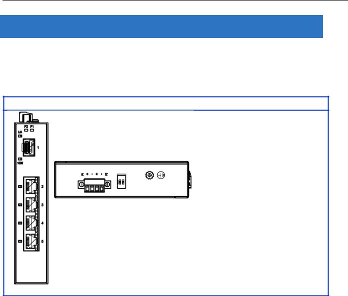
2.1 Faceplate
5-Port Series
10
12-Port Series
2.2 Front Panel Introduction
Front Panel
System Status LED |
P1, P2 and Alarm |
|
|
Gigabit Ethernet Copper Ports |
RJ45 |
|
|
Gigabit Ethernet SFP ports |
SFP Slots |
|
|
POE LED |
POE port status |
|
|
RR/RS LED |
Device info/status |
|
Models |
|
|
L2+ Managed Switch |
|
|
|
|
|
|
|
|
|
|
RGS200-12P |
||
|
|
|
|
||
|
|
|
|
|
|
|
Total Gigabit Ethernet |
12 |
|
||
|
Ports |
|
|||
|
|
|
|
||
|
|
|
|
||
|
10/100/1000 BaseT(X) |
8 |
|
||
|
|
|
|
||
|
100/1000 Base SFP |
4 |
|
||
|
|
|
|
|
|
11
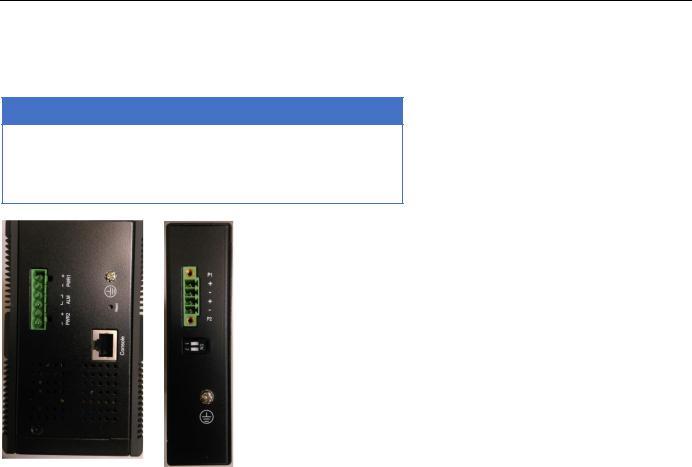
2.3 Top Panel Introduction
Top Panel
Power Input (Dual) |
6P Terminal Block |
|
|
Console (RS232) |
RJ45 |
|
|
Reset |
Push Button |
12

Quick Installation
Equipment Mounting
Cable Connecting
Equipment Configuration
13
3.Quick Installation
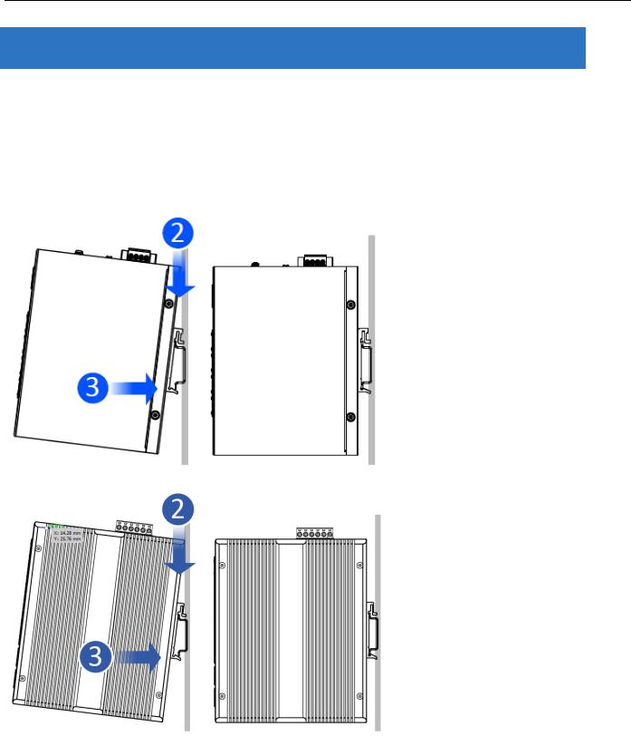
3.1 Mounting the RGS Series (DIN-Rail)
Mounting step:
1.Screw the DIN-Rail bracket on with the bracket and screws in the accessory kit.
2.Hook the unit over the DIN rail.
3.Push the bottom of the unit towards the DIN Rail until it snaps into place.
Figure 1 RGS100-5P DIN-Rail Mounting
Figure 2 RGS200-12P DIN-Rail Mounting
14
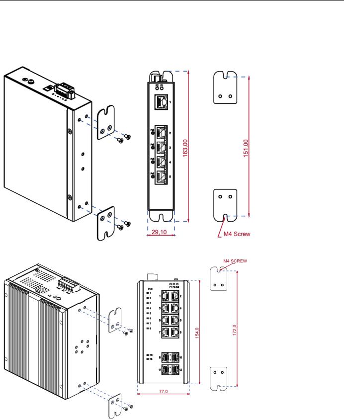
3.2 Mounting the RGS Series (Wall mount)
Mounting step:
1. Screw on the wall-mounting plate on with the plate and screws in the accessory kit.
Figure 3 RGS100-5P Series Wall Mounting
Figure 4 RGS200-12P Series Wall Mounting
15
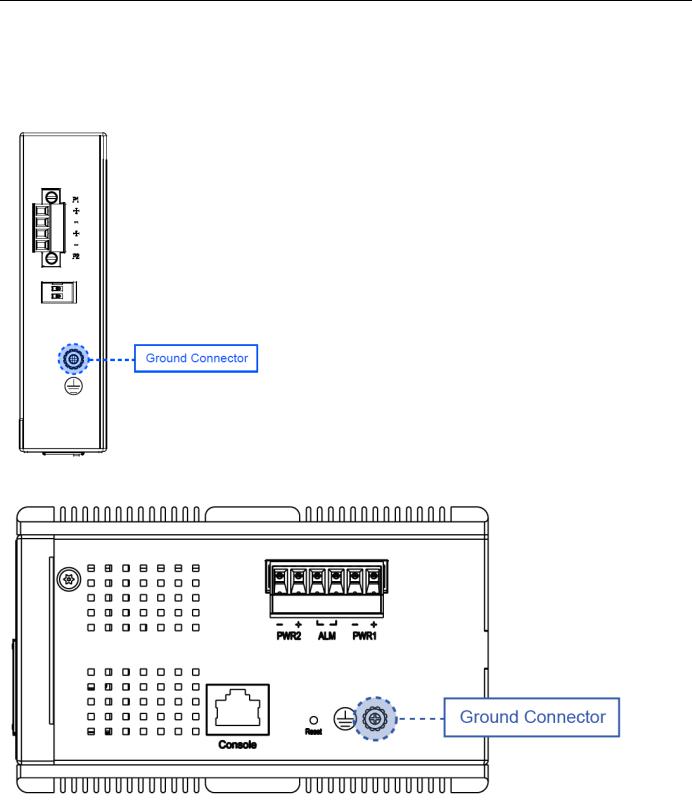
3.3 Ground Connections
RGS Series must be properly grounded for optimum system performance.
Figure 5 RGS100-5P Series Ground Connections
Figure 6 RGS200-12P Series Ground Connections
16
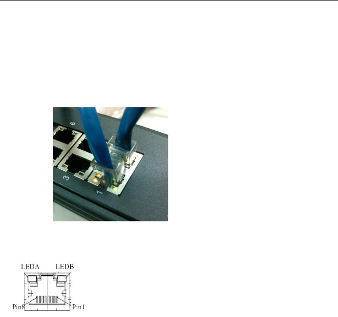
3.4 Connecting the Ethernet Interface (RJ45 Ethernet)
The switch provides two types of Ethernet interfaces: electrical (RJ45) and optical (SFP) interfaces. Connecting the Ethernet interface via RJ45:
To connect the switch to a PC, use straight-through or cross-over Ethernet cables.
To connect the switch to an Ethernet device, use UTP (Unshielded Twisted Pair) or STP (Shielded Twisted
Pair) Ethernet cables.
The pin assignment of RJ-45 connector is shown in the following figure and table.
The pin assignment of RJ-45 connector is shown in the following figure and table.
RGS Series
Pin |
Assignment |
|
|
1,2 |
T/Rx+,T/Rx- |
|
|
3,6 |
T/Rx+,T/Rx- |
|
|
4,5 |
T/Rx+,T/Rx- |
|
|
7,8 |
T/Rx+,T/Rx- |
|
|
RGS200-12P series
Pin |
Assignment |
PoE |
|
Assignment |
|||
|
|
||
|
|
|
|
1,2 |
T/Rx+,T/Rx- |
Positive VPort |
|
3,6 |
T/Rx+,T/Rx- |
Negative VPort |
|
|
|
|
|
4,5 |
T/Rx+,T/Rx- |
X |
|
|
|
|
|
7,8 |
T/Rx+,T/Rx- |
X |
|
|
|
|
17
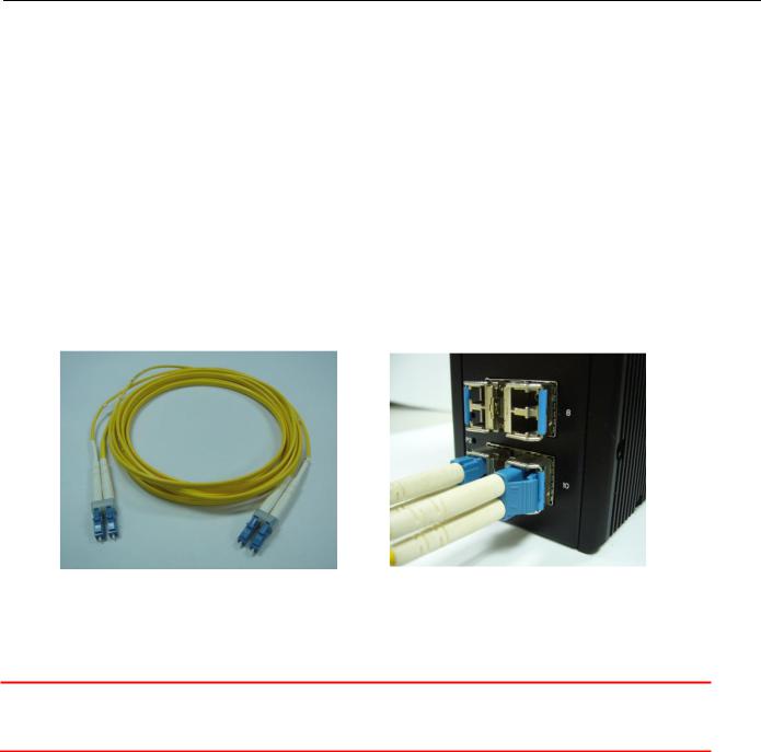
3.5 Connecting the Ethernet Interface (Fiber)
Prepare a proper SFP module and install it into the optical port. Then you can connect fiber optics cabling that uses LC connectors or SC connectors (with the use of an optional SC-to-LC adapter) to the fiber optics connector. For a 100 Mbps fiber port available, please prepare the LC connectors or SC connectors (with the use of an optional SC-to-LC adapter). They are also available with multimode, single mode, long-haul (for connections up to 120+ km) or special-application transceivers.
For a 1000 Mbps fiber port available, please use the mini-GBIC SFP (small form pluggable). These accept plug in fiber transceivers that typically have an LC style connector. They are available with multimode, single mode, long-haul (for connections up to 80+ km) or special-application transceivers.
For each fiber port there is a transmit (TX) and receive (RX) signal. Please make sure that the transmit (TX) port of the switch connects to the receiver (RX) port of the other device, and the receive (RX) port of the switch connects to the transmit (TX) port of the other device when making your fiber optic connections.
Refer to Table 1 for the normal operational LED status.
Fiber optics cable with LC duplex connector
Connect the optical fiber to the SFP socket
DANGER: Never attempt to view optical connectors that might be emitting laser energy.
Do not power up the laser product without connecting the laser to the optical fiber and putting the cover in position, as laser outputs will emit infrared laser light at this point.
18
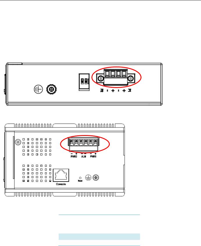
3.6 Power Connection
The DC power interface is a 6-pin terminal block with polarity signs on the top panel.
The RGS200-12P can be powered from two power supply (input range 12V – 58V). The DC power connector is a 6-pin terminal block; there is alarm contact on the middle terminal block.
Refer to Table 1 for the normal operational LED status.
Figure 7 RGS100-5P Series Power Connections
Figure 8 RGS200-12P Series Ground Connections
Power Connector (6P Terminal Block)
Input |
DC 12-58V |
|
|
PWR1 +/- Power Input 1 +/-
PWR2 +/- Power Input 2 +/-
ALM Alarm relay output
19
Note: 1. The DC power should be connected to a well-fused power supply.
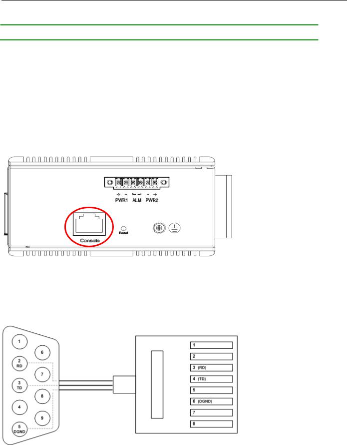
3.7 Console Connection
The Console port is for local management by using a terminal emulator or a computer with terminal emulation software.
DB9 connector connect to computer COM port
Baud rate: 115200bps
8 data bits, 1 stop bit
None parity
None flow control
Figure 10 RGS200-12P Series Ground Connections
To connect the host PC to the console port, a RJ45 (male) connector-to-RS232 DB9 (female) connector cable is required. The RJ45 connector of the cable is connected to the CID port of RGS200-12P; the DB9 connector of the cable is connected to the PC COM port. The pin assignment of the console cable is shown below:
20
3.8 System Reset
The Reset button is provided to reboot the system without the need to remove power. Under normal circumstances, you will not have to use it. However, or rare occasions, the RGS200-12P may not respond; then you may need to push the Reset button.
Reset Button
3.9 Web Interface Initialization (Optional)
Web Browser Support
IE 7 (or newer version) with the following default settings is recommended:
Language script |
Latin based |
|
|
Web page font |
Times New Roman |
|
|
Plain text font |
Courier New |
|
|
Encoding |
Unicode (UTF-8) |
|
|
Text size |
Medium |
|
|
Firefox with the following default settings is recommended:
Web page font |
Times New Roman |
|
|
Encoding |
Unicode (UTF-8) |
|
|
Text size |
16 |
|
|
21

Google Chrome with the following default settings is recommended:
Web page font |
Times New Roman |
|
|
Encoding |
Unicode (UTF-8) |
|
|
Text size |
Medium |
|
|
Connect and Login to RGS200-12P
1.Connecting to RGS200-12P Ethernet port (RJ45 Ethernet port).
2.Factory default IP: 192.168.1.1
3.Login with default account and password.
Username: admin Password: 1234
22
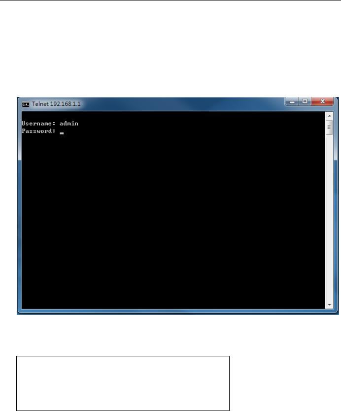
3.10 CLI Initialization and Configuration (Optional)
1.Connecting to RGS200-12P Ethernet port(RJ45 Ethernet port)
2.Key-in the command under Telnet: telnet 192.168.1.1
3.Login with default account and password.
Username: admin Password: 1234
4. Change the IP with commands listed below: CLI Command:
enable
configure terminal interface vlan 1
ip address xxx.xxx.xxx.xxx xxx.xxx.xxx.xxx exit
23
3.11 Monitoring the Ethernet Interface
By RJ45 Ethernet:
Refer to Figure 11 LED Indicators for monitoring 8 Gigabit Ethernet with copper connector (RJ45). Also refer toTable 1 for the normal operational LED status.
By SFP:
Refer to Figure 11 LED Indicators for monitoring 4 Gigabit Ethernet with SFP connector. Also refer to Table 1 for the normal operational LED status.
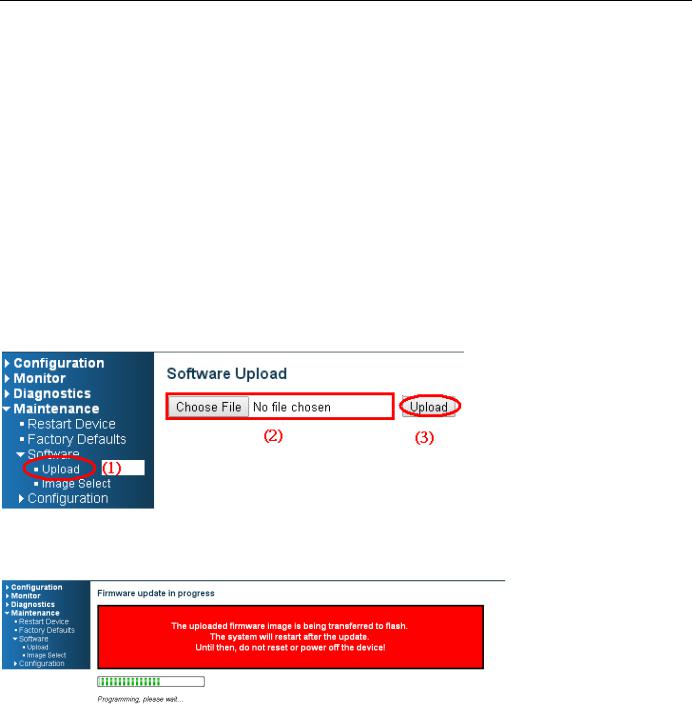
3.12 Upgrade Software
1.In Web UI, go to “MaintenanceSoftwareUpload” page.
2.Select software file, and click “Upload” button.
3.After starting to upload software to device, please don’t cold/warm start device and wait it auto reboot, then upgrade finished.
24

3.13 Reset to Default and Save Configure
Configuration via CLI command
To see what current interface and IP address is:
If the manager wants to reset the configuration to default, but keep management IP setting.
(1)Please execute this command: reload defaults keep-ip
(2)Check interface VLAN and IP address; confirm only management IP setting kept.
(3)Execute this command: copy running-config startup-config
If manager want to reset the all configuration to default completely
(1)Please execute this command: reload defaults
(2)Check interface VLAN and IP address, confirm they all change to default setting.
(3)Execute this command: copy running-config startup-config
25
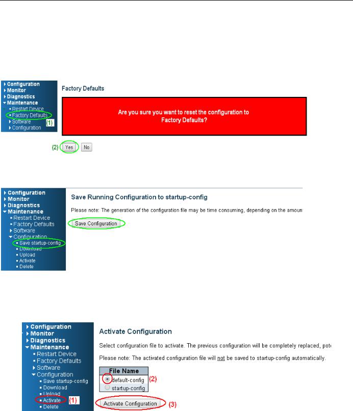
Configuration via WEB UI
If manager want to reset the configuration to default but keep management IP setting
(1)Go to “Maintenance””Factory Defaults” pagination to Click “Yes” button.
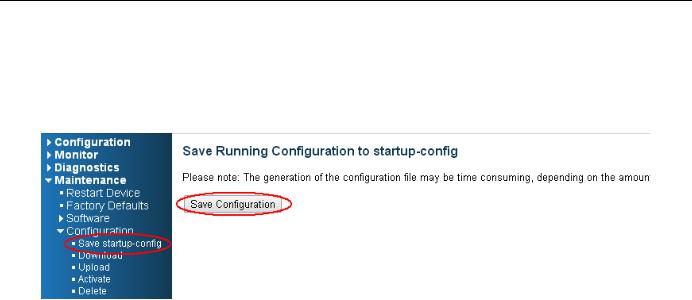
(2) Go to “Maintenance” “Configuration””Save startup-config” pagination, then click “Save Configuration” button, then reset successfully
.
If manager want to reset the all configuration to default completely
(1) Go to “Maintenance” “Configuration””Activate” pagination to select “default-config”, then click “Activate Configuration” button
26
(2) Change WEB’s IP be 192.0.2.1(default IP) to login DUT’s Web UI.
(3) Go to “Maintenance” “Configuration””Save startup-config” pagination, then click “Save Configuration” button, then reset successfully.
27

3.14 DIP Switch Setting for RGS100-5P
|
Pin No# |
|
|
Status |
|
|
5-Port (4TX+1SFP) with PoE |
|
|
|
|
|
|
|
|||
|
Pin 1 |
|
ON |
|
To enable Broadcast storm rate limit |
|||
|
|
|
|
OFF |
|
To disable Broadcast storm rate limit |
||
|
Pin 2 |
|
ON |
|
NOT USED |
|||
|
|
|
|
OFF |
|
NOT USED |
||
3.15 LED Status Indications
|
|
|
|
|
|
|
Table 1 LED Status Indicators |
|
|
|
|
|
|
|
|
|
|
|
|
|
|
|
|
|
|
|
|
LED |
|
|
Indicator |
|
|
Condition |
|
|
Name |
|
|
/color |
|
|
|
|
|
P1/P2 |
|
On Green |
|
P1/P2 power line has power |
|||
|
|
|
|
|
|
|
||
|
|
Off |
|
P1/P2 power line disconnect or does not have power supplied |
||||
|
|
|
|
|
||||
|
Alarm |
|
On Red |
|
Ethernet link fails, alarm or power failure alarm occurs |
|||
|
|
|
|
|
|
|
||
|
|
Off |
|
No Ethernet link fails and no power failure alarm |
||||
|
|
|
|
|
||||
|
|
|
|
|
|
|
||
|
|
|
|
On Green |
|
Ethernet link up but no traffic is detected |
||
|
Copper |
|
|
|
|
|
|
|
|
|
Flashing |
|
Ethernet link up and there is traffic detected |
||||
|
port |
|
|
|||||
|
|
Green |
|
|
|
|||
|
Link/Act |
|
|
|
|
|||
|
|
|
|
|
|
|
||
|
|
|
|
Off |
|
Ethernet link down |
||
|
|
|
|
|
|
|||
|
Copper |
|
On Yellow |
|
A 1000Mbps connection is detected |
|||
|
port |
|
Off |
|
No link, a 10Mbps or 100 Mbps connection is detected |
|||
|
Speed |
|
|
|||||
|
|
|
|
|
|
|
||
|
|
|
|
|
|
|||
|
SFP |
|
On Green |
|
Ethernet link up |
|||
|
port |
|
Off |
|
Ethernet link down |
|||
|
Link/A |
|
|
|||||
|
|
|
|
|
|
|
||
|
ct |
|
|
|
|
|
|
|
|
|
|
|
|
|
|||
|
SFP |
|
On Yellow |
|
SFP port speed 1000Mbps connection is detected. |
|||
|
port |
|
Off |
|
No link or a SFP port speed 100Mbps connection is detected |
|||
|
Speed |
|
|
|||||
|
|
|
|
|
|
|
||
|
|
|
|
|
|
|
||
|
POE |
|
On Green |
|
POE is working |
|||
|
|
|
|
|
|
|
||
|
|
Off |
|
POE is not working |
||||
|
|
|
|
|
||||
|
|
|
|
|
|
|
|
|
|
|
|
|
|
|
|
|
|
28
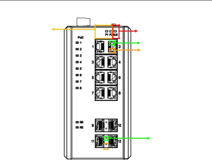
PWR LED Indicator |
ALM LED Indicator |
|
Copper Link/Act LED
Copper Speed LED
SFP Link LED Indicator

 SFP Speed LED
Indicator
Figure 11 LED Indicators
29
4.Introduction
4.1System Description
RGS Series delivers high quality, wide operating temperature range, extended power input range, IP-30 design, and advanced VLAN & QoS features. It’s ideal for harsh environments and mission critical applications.
RGS Series Managed QoS provides enterprise-class networking features to fulfill the needs of large network infrastructure and extreme environments.
RGS Series eases the effort to build a network infrastructure which offers a reliable, well managed and good QoS networking for any business requiring continuous and well-protected services in management environments. With the features such as Fast Failover ring protection and QoS, customers can ensure their network is qualified to deliver any real-time and high quality applications.
Note: The following web user guide is for RGS200-12P model.
4.2 Using the Web Interface
The object of this document “RGS Web Configuration Tool Guide” is to address the web feature, design layout and descript how to use the web interface.
4.2.1Web Browser Support
IE 7 (or newer version) with the following default settings is recommended:
Language script |
Latin based |
|
|
Web page font |
Times New Roman |
|
|
Plain text font |
Courier New |
|
|
Encoding |
Unicode (UTF-8) |
|
|
Text size |
Medium |
|
|
Firefox with the following default settings is recommended:
Web page font |
Times New Roman |
|
|
Encoding |
Unicode (UTF-8) |
|
|
Text size |
16 |
|
|
Google Chrome with the following default settings is recommended:
Web page font |
Times New Roman |
|
|
Encoding |
Unicode (UTF-8) |
|
|
30
Loading...