


Prestige 310
Broadband Sharing Gateway
User's Guide
Version 3.50
January 2002

Prestige 310 Broadband Sharing Gateway
Copyright
Copyright © 2002 by ZyXEL Communications Corporation.
The contents of this publication may not be reproduced in any part or as a whole, transcribed, stored in a
retrieval system, translated into any language, or transmitted in any form or by any means, electronic,
mechanical, magnetic, optical, chemical, photocopying, manual, or otherwise, without the prior written
permission of ZyXEL Communications Corporation.
Published by ZyXEL Communications Corporation. All rights reserved.
Disclaimer
ZyXEL does not assume any liability arising out of the application or use of any products, or software
described herein. Neither does it convey any license under its patent rights nor the patent rights of others.
ZyXEL further reserves the right to make changes in any products described herein without notice. This
publication is subject to change without notice.
Trademarks
ZyNOS (ZyXEL Network Operating System) is a registered trademark of ZyXEL Communications, Inc.
Other trademarks mentioned in this publication are used for identification purposes only and may be
properties of their respective owners.
ii Copyright

Prestige 310 Broadband Sharing Gateway
Federal Communications Commission (FCC)
Interference Statement
This device complies with Part 15 of FCC rules. Operation is subject to the following two conditions:
• This device may not cause harmful interference.
• This device must accept any interference received, including interference that may cause undesired
operations.
This equipment has been tested and found to comply with the limits for a Class B digital device pursuant to
Part 15 of the FCC Rules. These limits are designed to provide reasonable protection against harmful
interference in a commercial environment. This equipment generates, uses, and can radiate radio frequency
energy, and if not installed and used in accordance with the instructions, may cause harmful interference to
radio communications.
If this equipment does cause harmful interference to radio/television reception, which can be determined by
turning the equipment off and on, the user is encouraged to try to correct the interference by one or more of
the following measures:
1. Reorient or relocate the receiving antenna.
2. Increase the separation between the equipment and the receiver.
3. Connect the equipment into an outlet on a circuit different from that to which the receiver is connected.
4. Consult the dealer or an experienced radio/TV technician for help.
Notice
Changes or modifications not expressly approved by the party responsible for compliance could void the
user's authority to operate the equipment.
Certifications
Refer to the product page at www.zyxel.com.
FCC iii

Prestige 310 Broadband Sharing Gateway
Information for Canadian Users
The Industry Canada label identifies certified equipment. This certification means that the equipment meets
certain telecommunications network protective operation and safety requirements. The Industry Canada label
does not guarantee that the equipment will operate to a user's satisfaction.
Before installing this equipment, users should ensure that it is permissible to be connected to the facilities of
the local telecommunications company. The equipment must also be installed using an acceptable method of
connection. In some cases, the company's inside wiring associated with a single line individual service may
be extended by means of a certified connector assembly. The customer should be aware that compliance with
the above conditions may not prevent degradation of service in some situations.
Repairs to certified equipment should be made by an authorized Canadian maintenance facility designated by
the supplier. Any repairs or alterations made by the user to this equipment, or equipment malfunctions, may
give the telecommunications company cause to request the user to disconnect the equipment.
For their own protection, users should ensure that the electrical ground connections of the power utility,
telephone lines, and internal metallic water pipe system, if present, are connected together. This precaution
may be particularly important in rural areas.
Caution
Users should not attempt to make such connections themselves, but should contact the appropriate electrical
inspection authority, or electrician, as appropriate.
Note
This digital apparatus does not exceed the Class A limits for radio noise emissions from digital apparatus set
out in the radio interference regulations of Industry Canada.
iv Information for Canadian Users

Prestige 310 Broadband Sharing Gateway
Declaration of Conformity
We, the Manufacturer/Importer,
ZyXEL Communications Corporation
No. 6, Innovation Rd. II,
Science-Based Industrial Park,
Hsinchu, Taiwan, R.O.C., 300
declare that the product
Prestige 310
is in conformity with
(refer to the specification under which conformity is declared)
STANDARD STANDARD ITEM VERSION
EN 55022 Radio disturbance characteristics - Limits and method of measurement. 1998
EN 61000-3-2 Disturbance in supply system caused by household appliances and similar
electrical equipment "Harmonics".
EN 61000-3-3 Disturbance in supply system caused by household appliances and similar
electrical equipment "Voltage fluctuations".
EN 61000-4-2 Electrostatic discharge immunity test - Basic EMC Publication. 1995
EN 61000-4-3 Radiated radio-frequency electromagnetic field immunity test 1996
EN 61000-4-4 Electrical fast transient / burst immunity test - Basic EMC Publication. 1995
EN 61000-4-5 Surge immunity test. 1995
EN 61000-4-6 Immunity to conducted disturbances induced by radio-frequency fields. 1996
EN 61000-4-8 1993
EN61000-4-11 Voltage dips short interruptions and voltage variations immunity tests. 1994
1995
1995
Declaration of Conformity v

Prestige 310 Broadband Sharing Gateway
ZyXEL Limited Warranty
ZyXEL warrants to the original end user (purchaser) that this product is free from any defects in materials or
workmanship for a period of up to two years from the date of purchase. During the warranty period, and upon
proof of purchase, should the product have indications of failure due to faulty workmanship and/or materials,
ZyXEL will, at its discretion, repair or replace the defective products or components without charge for
either parts or labor, and to whatever extent it shall deem necessary to restore the product or components to
proper operating condition. Any replacement will consist of a new or re-manufactured functionally
equivalent product of equal value, and will be solely at the discretion of ZyXEL. This warranty shall not
apply if the product is modified, misused, tampered with, damaged by an act of God, or subjected to
abnormal working conditions.
Note
Repair or replacement, as provided under this warranty, is the exclusive remedy of the purchaser. This
warranty is in lieu of all other warranties, express or implied, including any implied warranty of
merchantability or fitness for a particular use or purpose. ZyXEL shall in no event be held liable for indirect
or consequential damages of any kind of character to the purchaser.
To obtain the services of this warranty, contact ZyXEL's Service Center for your Return Material
Authorization number (RMA). Products must be returned Postage Prepaid. It is recommended that the unit be
insured when shipped. Any returned products without proof of purchase or those with an out-dated warranty
will be repaired or replaced (at the discretion of ZyXEL) and the customer will be billed for parts and labor.
All repaired or replaced products will be shipped by ZyXEL to the corresponding return address, Postage
Paid. This warranty gives you specific legal rights, and you may also have other rights that vary from country
to country.
vi Warranty

Prestige 310 Broadband Sharing Gateway
Customer Support
Please have the following information ready when you contact customer support.
• Product model and serial number.
• Information in Menu 24.2.1 - System Information.
• Warranty information.
• Date that you received your device.
• Brief description of the problem and the steps you took to solve it.
METHOD
LOCATION
WORLDWIDE
NORTH
AMERICA
SCANDINAVIA
AUSTRIA
GERMANY
MALAYSIA
E-MAIL
SUPPORT/SALES
support@zyxel.com.tw +886-3-578-3942 www.zyxel.com
sales@zyxel.com.tw +886-3-578-2439 ftp.europe.zyxel.com
support@zyxel.com +1-714-632-0882
sales@zyxel.com +1-714-632-0858 ftp.zyxel.com
support@zyxel.dk +45-3955-0700 www.zyxel.dk
sales@zyxel.dk +45-3955-0707 ftp.zyxel.dk
support@zyxel.at +43-1-4948677-0 www.zyxel.at
sales@zyxel.at +43-1-4948678 ftp.zyxel.at
support@zyxel.de +49-2405-6909-0 www.zyxel.de
sales@zyxel.de +49-2405-6909-99
support@zyxel.com.my +603-795-44-688 www.zyxel.com.my
sales@zyxel.com.my +603-795-34-407
TELEPHONE/FAX WEB SITE/ FTP SITE REGULAR MAIL
www.europe.zyxel.com
www.zyxel.com
800-255-4101
ZyXEL Communications Corp.,
6 Innovation Road II, ScienceBased Industrial Park,
HsinChu, Taiwan 300, R.O.C.
ZyXEL Communications Inc.,
1650 Miraloma Avenue,
Placentia, CA 92870, U.S.A.
ZyXEL Communications A/S,
Columbusvej 5, 2860 Soeborg,
Denmark.
ZyXEL Communications
Services GmbH. Thaliastrasse
125a/2/2/4 A-1160 Vienna,
Austria
ZyXEL Deutschland GmbH.
Adenauerstr. 20/A4 D-52146
Wuerselen, Germany
Lot B2-06, PJ Industrial Park,
Section 13, Jalan Kemajuan,
46200 Petaling Jaya Selangor
Darul Ehasn, Malaysia
Customer Support vii

Prestige 310 Broadband Sharing Gateway
Table of Contents
Copyright.......................................................................................................................................................... ii
Federal Communications Commission (FCC) Interference Statement .....................................................iii
Information for Canadian Users ................................................................................................................... iv
Declaration of Conformity .............................................................................................................................. v
ZyXEL Limited Warranty .............................................................................................................................vi
Customer Support .........................................................................................................................................vii
List of Figures................................................................................................................................................xiv
List of Tables ...............................................................................................................................................xviii
Preface ............................................................................................................................................................xx
PART I: GETTING STARTED.......................................................................................................................I
Chapter 1 Getting to Know Your Prestige..................................................................................................1-1
1.1 The Prestige 310 Broadband Sharing Gateway...............................................................................1-1
1.2 Features of the Prestige 310............................................................................................................1-1
1.2.1 10/100MB Auto-negotiation Ethernet/Fast Ethernet Interface ...............................................1-1
1.2.2 SNMP ..................................................................................................................................... 1-1
1.2.3 NAT (Network Address Translation)......................................................................................1-1
1.2.4 Traffic Redirect....................................................................................................................... 1-2
1.2.5 Port Forwarding ...................................................................................................................... 1-2
1.2.6 Trigger Port Forwarding .........................................................................................................1-2
1.2.7 Internal SPTGEN ....................................................................................................................1-2
1.2.8 DHCP Support ........................................................................................................................1-2
1.2.9 Dynamic DNS Support ........................................................................................................... 1-2
1.2.10 IP Multicast............................................................................................................................. 1-2
1.2.11 PPPoE Support........................................................................................................................1-3
1.2.12 PPTP Support..........................................................................................................................1-3
1.2.13 IP Alias ...................................................................................................................................1-3
1.2.14 Call Scheduling.......................................................................................................................1-3
1.2.15 Call Control.............................................................................................................................1-3
1.2.16 Full Network Management .....................................................................................................1-3
1.2.17 RoadRunner Support...............................................................................................................1-3
1.2.18 Time and Date Setting.............................................................................................................1-3
1.2.19 Logging and Tracing...............................................................................................................1-4
1.2.20 Embedded FTP and TFTP Servers..........................................................................................1-4
1.2.21 Packet Filtering .......................................................................................................................1-4
1.2.22 Upgrade Prestige Firmware via LAN .....................................................................................1-4
1.3 Applications for the Prestige 310.................................................................................................... 1-4
1.3.1 Broadband Internet Access via Cable or DSL Modem ...........................................................1-4
1.4 Internet Access Configuration Checklist ........................................................................................1-5
Chapter 2 Hardware Installation and Initial Setup...................................................................................2-1
viii Table of Contents

Prestige 310 Broadband Sharing Gateway
2.1 Front Panel LEDs and Rear Panel Ports......................................................................................... 2-1
2.1.1 Front Panel LEDs ................................................................................................................... 2-1
2.2 Prestige 310 Rear Panel and Connections......................................................................................2-2
2.2.1 Connecting the Console Port.................................................................................................. 2-3
2.2.2 Connecting the Prestige to the Broadband Modem ................................................................ 2-3
2.2.3 Connecting the Prestige to the LAN....................................................................................... 2-3
2.2.4 Connecting the Power Adapter to your Prestige .................................................................... 2-4
2.2.5 Grounding the Prestige (Optional) ......................................................................................... 2-4
2.3 Additional Installation Requirements............................................................................................. 2-4
2.4 Turning on Your Prestige ............................................................................................................... 2-4
2.4.1 Initial Screen .......................................................................................................................... 2-4
2.4.2 Entering the Password ............................................................................................................ 2-5
2.5 Navigating the SMT Interface........................................................................................................ 2-5
2.5.1 Main Menu ............................................................................................................................. 2-6
2.5.2 System Management Terminal Interface Summary ............................................................... 2-7
2.5.3 SMT Menus at a Glance......................................................................................................... 2-8
2.6 Changing the System Password ................................................................................................... 2-10
2.6.1 Resetting the Prestige ........................................................................................................... 2-10
2.7 General Setup................................................................................................................................2-11
2.7.1 Dynamic DNS ...................................................................................................................... 2-11
2.7.2 Procedure For Configuring Menu 1 ..................................................................................... 2-12
2.7.3 Configuring Dynamic DNS.................................................................................................. 2-12
2.8 WAN Setup .................................................................................................................................. 2-14
2.9 LAN Setup ................................................................................................................................... 2-15
2.9.1 LAN Port Filter Setup .......................................................................................................... 2-16
Chapter 3 Internet Access ........................................................................................................................... 3-1
3.1 TCP/IP and DHCP for LAN........................................................................................................... 3-1
3.1.1 Factory LAN Defaults............................................................................................................ 3-1
3.1.2 DHCP Configuration.............................................................................................................. 3-1
3.1.3 IP Address and Subnet Mask.................................................................................................. 3-2
3.1.4 Private IP Addresses............................................................................................................... 3-3
3.1.5 RIP Setup ............................................................................................................................... 3-3
3.1.6 IP Multicast ............................................................................................................................ 3-4
3.1.7 IP Alias................................................................................................................................... 3-4
3.2 TCP/IP and DHCP Ethernet Setup................................................................................................. 3-5
3.2.1 IP Alias Setup......................................................................................................................... 3-7
3.3 Internet Access Setup..................................................................................................................... 3-8
3.3.1 Ethernet Encapsulation........................................................................................................... 3-8
3.3.2 PPTP Encapsulation ............................................................................................................. 3-10
3.3.3 Configure PPTP Client......................................................................................................... 3-10
3.3.4 PPPoE Encapsulation ........................................................................................................... 3-11
Table of Contents ix

Prestige 310 Broadband Sharing Gateway
3.4 Internet Test Setup ........................................................................................................................3-13
3.5 Basic Setup Complete...................................................................................................................3-13
PART II: ADVANCED APPLICATIONS ....................................................................................................II
Chapter 4 Remote Node Setup.....................................................................................................................4-1
4.1 Remote Node Profile.......................................................................................................................4-1
4.1.1 Ethernet Encapsulation ...........................................................................................................4-1
4.2 PPTP Encapsulation........................................................................................................................4-3
4.2.1 PPPoE Encapsulation.............................................................................................................. 4-4
4.3 Editing TCP/IP Options (with Ethernet Encapsulation)..................................................................4-6
4.3.1 Editing TCP/IP Options (with PPTP Encapsulation) ..............................................................4-8
4.3.2 Editing TCP/IP Options (with PPPoE Encapsulation) .......................................................... 4-10
4.4 Remote Node Filter.......................................................................................................................4-10
4.5 Traffic Redirect .............................................................................................................................4-11
4.5.1 Traffic Redirect Setup...........................................................................................................4-12
Chapter 5 IP Static Route Setup..................................................................................................................5-1
5.1 IP Static Route Setup ...................................................................................................................... 5-2
Chapter 6 Network Address Translation (NAT) ........................................................................................ 6-1
6.1 Introduction.....................................................................................................................................6-1
6.1.1 NAT Definitions .....................................................................................................................6-1
6.1.2 What NAT Does .....................................................................................................................6-2
6.1.3 How NAT Works.................................................................................................................... 6-2
6.1.4 NAT Application ....................................................................................................................6-3
6.1.5 NAT Mapping Types ..............................................................................................................6-4
6.2 Using NAT ......................................................................................................................................6-5
6.2.1 SUA (Single User Account) Versus NAT ..............................................................................6-5
6.2.2 Applying NAT ........................................................................................................................6-6
6.3 NAT Setup.......................................................................................................................................6-7
6.3.1 Address Mapping Sets ............................................................................................................6-8
6.4 NAT Server Sets – Port Forwarding..............................................................................................6-12
6.4.1 Configuring a Server behind NAT........................................................................................6-13
6.5 General NAT Examples ................................................................................................................6-15
6.5.1 Example 1: Internet Access Only.......................................................................................... 6-15
6.5.2 Example 2: Internet Access with an Inside Server................................................................ 6-16
6.5.3 Example 3: Multiple Public IP Addresses With Inside Servers ............................................6-17
6.5.4 Example 4: NAT Unfriendly Application Programs.............................................................6-21
6.6 Trigger Port Forwarding ...............................................................................................................6-22
6.6.1 Two Points To Remember About Trigger Ports ...................................................................6-23
6.6.2 Trigger Port Forwarding Process..........................................................................................6-24
PART III: ADVANCED MANAGEMENT................................................................................................. III
Chapter 7 Filter Configuration ...................................................................................................................7-1
7.1 About Filtering................................................................................................................................7-1
x Table of Contents

Prestige 310 Broadband Sharing Gateway
7.1.1 The Filter Structure of the Prestige ........................................................................................ 7-2
7.2 Configuring a Filter Set.................................................................................................................. 7-4
7.2.1 Filter Rules Summary Menu ..................................................................................................7-5
7.2.2 Configuring a Filter Rule ....................................................................................................... 7-7
7.2.3 TCP/IP Filter Rule.................................................................................................................. 7-7
7.2.4 Generic Filter Rule ............................................................................................................... 7-11
7.3 Example Filter.............................................................................................................................. 7-13
7.4 Filter Types and NAT ................................................................................................................... 7-16
7.5 Applying a Filter and Factory Defaults........................................................................................ 7-17
7.5.1 LAN Traffic ......................................................................................................................... 7-17
7.5.2 Remote Node Filters............................................................................................................. 7-18
Chapter 8 SNMP Configuration ................................................................................................................. 8-1
8.1 About SNMP.................................................................................................................................. 8-1
8.2 Supported MIBs............................................................................................................................. 8-2
8.3 SNMP Configuration...................................................................................................................... 8-2
8.4 SNMP Traps................................................................................................................................... 8-3
Chapter 9 System Information and Diagnosis........................................................................................... 9-1
9.1 System Status................................................................................................................................. 9-1
9.1.1 To get to the System Status:................................................................................................... 9-1
9.2 System Information and Console Port Speed................................................................................. 9-3
9.2.1 System Information................................................................................................................ 9-4
9.2.2 Console Port Speed ................................................................................................................ 9-5
9.3 Log and Trace ................................................................................................................................ 9-5
9.3.1 Viewing Error Log ................................................................................................................. 9-5
9.3.2 UNIX Syslog.......................................................................................................................... 9-6
9.3.3 Call-Triggering Packet ......................................................................................................... 9-10
9.4 Diagnostic .....................................................................................................................................9-11
9.4.1 WAN DHCP......................................................................................................................... 9-11
Chapter 10 Firmware and Configuration Maintenance......................................................................... 10-1
10.1 Filename Conventions.................................................................................................................. 10-1
10.2 Backup Configuration .................................................................................................................. 10-2
10.2.1 Backup Configuration .......................................................................................................... 10-2
10.2.2 Using the FTP Command from the DOS Prompt................................................................. 10-3
10.2.3 Backup Configuration Using TFTP ..................................................................................... 10-5
10.2.4 TFTP Command Example.................................................................................................... 10-5
10.2.5 Backup Via Console Port ..................................................................................................... 10-6
10.3 Restore Configuration .................................................................................................................. 10-7
10.3.1 Restore Using FTP or TFTP................................................................................................. 10-8
10.3.2 Restore Via Console Port ..................................................................................................... 10-9
10.4 Uploading Firmware and Configuration Files............................................................................ 10-10
10.4.1 Firmware File Upload ........................................................................................................ 10-10
Table of Contents xi

Prestige 310 Broadband Sharing Gateway
10.4.2 Configuration File Upload ..................................................................................................10-11
10.4.3 TFTP File Upload ...............................................................................................................10-13
10.4.4 Uploading Via Console Port ...............................................................................................10-14
Chapter 11 System Maintenance and Information .................................................................................. 11- 1
11.1 Command Interpreter Mode..........................................................................................................11-1
11.2 Call Control Support.....................................................................................................................11-2
11.2.1 Budget Management ............................................................................................................. 11-2
11.2.2 Call History........................................................................................................................... 11-3
11.3 Time and Date Setting...................................................................................................................11-4
11.3.1 Resetting the Time ................................................................................................................ 11-6
Chapter 12 Internal SPTGEN ...................................................................................................................12-1
12.1 The Configuration Text File Format .............................................................................................12-1
12.1.1 Internal SPTGEN File Modification - Important Points to Remember.................................12-2
12.2 Internal SPTGEN FTP Download Example..................................................................................12-3
12.3 Internal SPTGEN FTP Upload Example ......................................................................................12-4
Chapter 13 Remote Management..............................................................................................................13-1
13.1 Telnet ............................................................................................................................................13-1
13.2 FTP ...............................................................................................................................................13-1
13.3 Web ...............................................................................................................................................13-1
13.4 SNMP ...........................................................................................................................................13-1
13.5 DNS ..............................................................................................................................................13-2
13.6 Remote Management ....................................................................................................................13-2
13.6.1 Remote Management Limitations.........................................................................................13-4
13.7 Remote Management and NAT.....................................................................................................13-4
13.8 System Timeout ............................................................................................................................13-4
Chapter 14 Call Scheduling .......................................................................................................................14-1
14.1 Introduction...................................................................................................................................14-1
14.2 Schedule Setup..............................................................................................................................14-1
14.3 Schedule Set Setup........................................................................................................................14-2
14.4 Applying Schedule Sets to Remote Nodes....................................................................................14-3
PART IV: TROUBLESHOOTING AND ADDITIONAL INFORMATION............................................IV
Chapter 15 Troubleshooting ......................................................................................................................15-1
15.1 Problems Starting Up the Prestige ................................................................................................15-1
15.2 Problems with the LAN Interface ................................................................................................. 15-1
15.3 Problems with the WAN Interface ................................................................................................15-2
15.4 Problems with Internet Access......................................................................................................15-2
15.5 Problems with the Password ......................................................................................................... 15-3
15.6 Problems with Remote Management ............................................................................................ 15-3
Appendix A TCP/IP........................................................................................................................................ A
Appendix B PPPoE..........................................................................................................................................F
Appendix C PPTP........................................................................................................................................... H
xii Table of Contents

Prestige 310 Broadband Sharing Gateway
Appendix D Example Internal SPTGEN Screens ........................................................................................K
Appendix E Boot Commands......................................................................................................................... N
Appendix F Power Adapter Specifications ................................................................................................... P
Appendix G Hardware Specifications ........................................................................................................... Q
Index................................................................................................................................................................. R
Table of Contents xiii

Prestige 310 Broadband Sharing Gateway
List of Figures
Figure 1-1 Internet Access Application ..........................................................................................................1-4
Figure 2-1 Front Panel LEDs..........................................................................................................................2-1
Figure 2-2 Prestige 310 Rear Panel Connections............................................................................................2-2
Figure 2-3 Initial Screen .................................................................................................................................2-5
Figure 2-4 Password Screen............................................................................................................................2-5
Figure 2-5 Prestige 310 Main Menu...............................................................................................................2-7
Figure 2-6 Getting Started and Advanced Application SMT Menus..............................................................2-8
Figure 2-7 Advanced Management SMT Menus............................................................................................2-9
Figure 2-8 Menu 23 — System Password ....................................................................................................2-10
Figure 2-9 Menu 1 — General Setup............................................................................................................2-12
Figure 2-10 Configure Dynamic DNS ......................................................................................................... 2-13
Figure 2-11 Menu 2 — WAN Setup .............................................................................................................2-14
Figure 2-12 Menu 3 — LAN Setup .............................................................................................................. 2-15
Figure 2-13 Menu 3.1 - LAN Port Filter Setup.............................................................................................2-16
Figure 3-1 Physical Network .......................................................................................................................... 3-4
Figure 3-2 Partitioned Logical Networks........................................................................................................3-4
Figure 3-3 Menu 3 — LAN Setup (10/100 Mbps Ethernet)..........................................................................3-5
Figure 3-4 Menu 3.2 — TCP/IP and DHCP Ethernet Setup ..........................................................................3-5
Figure 3-5 Menu 3.2.1 — IP Alias Setup .......................................................................................................3-7
Figure 3-6 Internet Access Setup (Ethernet)...................................................................................................3-9
Figure 3-7 Internet Access Setup (PPTP) ..................................................................................................... 3-11
Figure 3-8 Internet Access (PPPoE) .............................................................................................................3-12
Figure 3-9 Internet Setup Test Example .......................................................................................................3-13
Figure 4-1 Remote Node Profile for Ethernet Encapsulation.........................................................................4-1
Figure 4-2 Remote Node Profile for PPTP Encapsulation..............................................................................4-3
Figure 4-3 Menu 11.1 Remote Node Profile for PPPoE Encapsulation..........................................................4-5
Figure 4-4 Remote Node Network Layer Options..........................................................................................4-7
Figure 4-5 Remote Node Network Layer Options .........................................................................................4-8
Figure 4-6 Remote Node Filter (Ethernet Encapsulation) ............................................................................4-10
Figure 4-7 Remote Node Filter (PPTP/PPPoE Encapsulation).....................................................................4-11
Figure 4-8 Traffic Redirect Hardware Setup................................................................................................. 4-11
Figure 4-9 Menu 11.1 — Remote Node Profile............................................................................................4-12
Figure 4-10 Menu 11.6 — Traffic Redirect Setup ........................................................................................4-13
Figure 5-1 Example of Static Routing Topology ............................................................................................5-1
Figure 5-2 Menu 12 — IP Static Route Setup ................................................................................................5-2
Figure 5-3 Menu 12. 1 — Edit IP Static Route...............................................................................................5-2
Figure 6-1 How NAT Works...........................................................................................................................6-3
Figure 6-2 NAT Application With IP Alias ....................................................................................................6-4
Figure 6-3 Menu 4 — Applying NAT for Internet Access ............................................................................. 6-6
xiv List of Figures

Prestige 310 Broadband Sharing Gateway
Figure 6-4 Menu 11.3 — Applying NAT to the Remote Node ...................................................................... 6-7
Figure 6-5 Menu 15 — NAT Setup................................................................................................................ 6-8
Figure 6-6 Menu 15.1 — Address Mapping Sets........................................................................................... 6-8
Figure 6-7 Menu 15.1.255 – SUA Address Mapping Rules .......................................................................... 6-9
Figure 6-8 Menu 15.1.1 — First Set ............................................................................................................ 6-10
Figure 6-9 Menu 15.1.1.1 — Editing/Configuring an Individual Rule in a Set............................................6-11
Figure 6-10 Menu 15.2 — NAT Server Setup.............................................................................................. 6-14
Figure 6-11 Multiple Servers Behind NAT Example................................................................................... 6-14
Figure 6-12 NAT Example 1 ........................................................................................................................ 6-15
Figure 6-13 Menu 4 — Internet Access and NAT Example......................................................................... 6-15
Figure 6-14 NAT Example 2 ........................................................................................................................ 6-16
Figure 6-15 Menu 15.2 — Specifying an Inside Server............................................................................... 6-17
Figure 6-16 NAT Example 3 ........................................................................................................................ 6-18
Figure 6-17 Example 3: Menu 11.3.............................................................................................................. 6-19
Figure 6-18 Example 3: Menu 15.1.1.1 ....................................................................................................... 6-19
Figure 6-19 Example 3: Final Menu 15.1.1 ................................................................................................. 6-20
Figure 6-20 Example 3: Menu 15.2 ............................................................................................................. 6-20
Figure 6-21 NAT Example 4 ........................................................................................................................ 6-21
Figure 6-22 Example 4: Menu 15.1.1.1 — Address Mapping Rule............................................................. 6-22
Figure 6-23 Example 4: Menu 15.1.1 — Address Mapping Rules .............................................................. 6-22
Figure 6-24 Menu 15.3—Trigger Port Setup ............................................................................................... 6-23
Figure 6-25 Trigger Port Forwarding Process — Example.......................................................................... 6-24
Figure 7-1 Outgoing Packet Filtering Process ............................................................................................... 7-1
Figure 7-2 Filter Rule Process........................................................................................................................ 7-3
Figure 7-3 Menu 21 — Filter Set Configuration............................................................................................ 7-4
Figure 7-4 NetBIOS_WAN Filter Rules Summary ........................................................................................ 7-4
Figure 7-5 NetBIOS _LAN Filter Rules Summary ....................................................................................... 7-5
Figure 7-6 TEL_FTP_WEB_WAN Filter Rules Summary............................................................................ 7-5
Figure 7-7 SNMP_WAN Filter Rules Summary............................................................................................ 7-5
Figure 7-8 Menu 21.1.1 — TCP/IP Filter Rule.............................................................................................. 7-7
Figure 7-9 Executing an IP Filter................................................................................................................. 7-10
Figure 7-10 Menu 21.6.1 — Generic Filter Rule..........................................................................................7-11
Figure 7-11 Filter Example .......................................................................................................................... 7-13
Figure 7-12 Example Filter — Menu 21.6.1................................................................................................ 7-14
Figure 7-13 Example Filter Rules Summary — Menu 21.3 ........................................................................ 7-15
Figure 7-14 Example Filter Rules Summary................................................................................................ 7-16
Figure 7-15 Protocol and Device Filter Sets ................................................................................................ 7-17
Figure 7-16 Filtering LAN Traffic ............................................................................................................... 7-17
Figure 7-17 Filtering Remote Node Traffic ................................................................................................. 7-18
Figure 8-1 SNMP Management Model.......................................................................................................... 8-1
Figure 8-2 Menu 22 — SNMP Configuration................................................................................................ 8-3
List of Figures xv

Prestige 310 Broadband Sharing Gateway
Figure 9-1 Menu 24 — System Maintenance.................................................................................................9-1
Figure 9-2 Menu 24.1 — System Maintenance — Status...............................................................................9-2
Figure 9-3 Menu 24.2 — System Information and Console Port Speed.........................................................9-4
Figure 9-4 Menu 24.2.1 System Maintenance — Information ......................................................................9-4
Figure 9-5 Menu 24.2.2 — System Maintenance — Change Console Port Speed......................................... 9-5
Figure 9-6 Examples of Error and Information Messages ..............................................................................9-6
Figure 9-7 Examples of Error and Information Messages ..............................................................................9-6
Figure 9-8 Menu 24.3.2 — System Maintenance — UNIX Syslog................................................................9-7
Figure 9-9 Call-Triggering Packet Example .................................................................................................9-10
Figure 9-10 Menu 24.4 — System Maintenance — Diagnostic................................................................... 9-11
Figure 9-11 WAN & LAN DHCP.................................................................................................................9-12
Figure 10-1 Telnet in Menu 24.5 ..................................................................................................................10-3
Figure 10-2 FTP Session Example ...............................................................................................................10-4
Figure 10-3 System Maintenance — Backup Configuration ........................................................................ 10-6
Figure 10-4 System Maintenance — Starting Xmodem Download Screen..................................................10-6
Figure 10-5 Backup Configuration Example................................................................................................10-7
Figure 10-6 Successful Backup Confirmation Screen ..................................................................................10-7
Figure 10-7 Telnet into Menu 24.6 ...............................................................................................................10-8
Figure 10-8 Restore Using FTP or TFTP Session Example .........................................................................10-9
Figure 10-9 System Maintenance — Restore Configuration ........................................................................ 10-9
Figure 10-10 System Maintenance — Starting Xmodem Download Screen................................................10-9
Figure 10-11 Restore Configuration Example ............................................................................................10-10
Figure 10-12 Successful Restoration Confirmation Screen........................................................................10-10
Figure 10-13 Telnet Into Menu 24.7.1 — Upload System Firmware ........................................................10-11
Figure 10-14 Telnet Into Menu 24.7.2 — System Maintenance.................................................................10-12
Figure 10-15 FTP Session Example of Firmware File Upload...................................................................10-13
Figure 10-16 Menu 24.7.1 as seen using the Console Port.........................................................................10-14
Figure 10-17 Example Xmodem Upload.................................................................................................... 10-15
Figure 10-18 Menu 24.7.2 as seen using the Console Port.........................................................................10-16
Figure 10-19 Example Xmodem Upload.................................................................................................... 10-17
Figure 11-1 Command Mode in Menu 24.....................................................................................................11-1
Figure 11-2 Valid Commands .......................................................................................................................11-2
Figure 11-3 Call Control............................................................................................................................... 11-2
Figure 11-4 Budget Management..................................................................................................................11-3
Figure 11-5 Call History............................................................................................................................... 11-4
Figure 11-6 Menu 24 — System Maintenance .............................................................................................11-5
Figure 11-7 Menu 24.10 System Maintenance — Time and Date Setting....................................................11-5
Figure 12-1 Configuration Text File Format — Column Descriptions.........................................................12-2
Figure 12-2 Internal SPTGEN FTP Download Example..............................................................................12-3
Figure 12-3 Internal SPTGEN FTP Upload Example...................................................................................12-4
Figure 13-1 Telnet Configuration on a TCP/IP Network..............................................................................13-1
xvi List of Figures

Prestige 310 Broadband Sharing Gateway
Figure 13-2 Menu 24.11 — Remote Management Control.......................................................................... 13-3
Figure 14-1 Schedule Setup ......................................................................................................................... 14-1
Figure 14-2 Schedule Set Setup ................................................................................................................... 14-2
Figure 14-3 Applying Schedule Sets to a Remote Node Example (PPPoE Encapsulation)......................... 14-4
Figure 14-4 Applying Schedule Sets to a Remote Node Example (PPTP Encapsulation)........................... 14-4
List of Figures xvii

Prestige 310 Broadband Sharing Gateway
List of Tables
Table 1-1 Internet Access Configuration Checklist ........................................................................................1-5
Table 2-1 LED Descriptions ...........................................................................................................................2-1
Table 2-2 Ethernet Cable Requirements and the Uplink Button.....................................................................2-3
Table 2-3 Main Menu Commands ..................................................................................................................2-6
Table 2-4 Main Menu Summary.....................................................................................................................2-7
Table 2-5 General Setup Menu Fields...........................................................................................................2-12
Table 2-6 Configure Dynamic DNS Menu Fields.........................................................................................2-13
Table 2-7 WAN Setup Menu Fields ..............................................................................................................2-15
Table 3-1 Example of Network Properties for LAN Servers with Fixed IP Addresses .................................. 3-2
Table 3-2 Private IP Address Ranges..............................................................................................................3-3
Table 3-3 LAN DHCP Setup Menu Fields .....................................................................................................3-6
Table 3-4 LAN TCP/IP Setup Menu Fields....................................................................................................3-6
Table 3-5 IP Alias Setup Menu Fields ............................................................................................................3-8
Table 3-6 Internet Access Setup Menu Fields.................................................................................................3-9
Table 3-7 New Fields in Menu 4 (PPTP) Screen.......................................................................................... 3-11
Table 3-8 New Fields in Menu 4 (PPPoE) Screen........................................................................................3-12
Table 4-1 Fields in Menu 11.1 (Ethernet Encapsulation)................................................................................4-2
Table 4-2 Fields in Menu 11.1 (PPTP Encapsulation) ....................................................................................4-3
Table 4-3 Table 4-3 Fields in Menu 11.1 (PPPoE Encapsulation Specific Only) ........................................... 4-5
Table 4-4 Remote Node Network Layer Options Menu Fields.......................................................................4-7
Table 4-5 Remote Node Network Layer Options Menu Fields.......................................................................4-9
Table 4-6 Menu 11.1 — Remote Node Profile (Traffic Redirect Field) .......................................................4-12
Table 4-7 Traffic Redirect Setup...................................................................................................................4-13
Table 5-1 IP Static Route Menu Fields ...........................................................................................................5-3
Table 6-1 NAT Definitions..............................................................................................................................6-1
Table 6-2 NAT Mapping Types.......................................................................................................................6-5
Table 6-3 Applying NAT in Menus 4 and 11.3...............................................................................................6-7
Table 6-4 SUA Address Mapping Rules.........................................................................................................6-9
Table 6-5 Fields in Menu 15.1.1................................................................................................................... 6-11
Table 6-6 Menu 15.1.1.1 — Editing/Configuring an Individual Rule in a Set .............................................6-12
Table 6-7 Services & Port Numbers .............................................................................................................6-13
Table 6-8 Menu 15.3—Trigger Port Setup Description................................................................................6-23
Table 7-1 Abbreviations Used in the Filter Rules Summary Menu ................................................................ 7-6
Table 7-2 Rule Abbreviations Used................................................................................................................ 7-6
Table 7-3 TCP/IP Filter Rule Menu Fields .....................................................................................................7-7
Table 7-4 Generic Filter Rule Menu Fields...................................................................................................7-11
Table 8-1 SNMP Configuration Menu Fields.................................................................................................8-3
Table 8-2 SNMP Traps ...................................................................................................................................8-4
Table 9-1 System Maintenance — Status Menu Fields ..................................................................................9-2
xviii List of Tables

Prestige 310 Broadband Sharing Gateway
Table 9-2 Fields in System Maintenance ....................................................................................................... 9-4
Table 9-3 System Maintenance Menu Syslog Parameters.............................................................................. 9-7
Table 9-4 System Maintenance Menu Diagnostic........................................................................................ 9-12
Table 10-1 Filename Conventions................................................................................................................ 10-2
Table 10-2 General Commands for Third Party FTP Clients....................................................................... 10-4
Table 10-3 General Commands for Third Party TFTP Clients .................................................................... 10-6
Table 11-1 Budget Management ...................................................................................................................11-3
Table 11-2 Call History Fields ......................................................................................................................11-4
Table 11-3 Time and Date Setting Fields ......................................................................................................11-5
Table 13-1 Menu 24.11 — Remote Management Control ........................................................................... 13-3
Table 14-1 Schedule Set Setup Fields.......................................................................................................... 14-2
Table 15-1 Troubleshooting the Start-Up of your Prestige .......................................................................... 15-1
Table 15-2 Troubleshooting the LAN Interface ........................................................................................... 15-1
Table 15-3 Troubleshooting the WAN interface........................................................................................... 15-2
Table 15-4 Internet Access........................................................................................................................... 15-2
Table 15-5 Troubleshooting the Password ................................................................................................... 15-3
Table 15-6 Troubleshooting Remote Management ...................................................................................... 15-3
List of Tables xix

Prestige 310 Broadband Sharing Gateway
Preface
About Your Gateway
Congratulations on your purchase of the Prestige 310 Broadband Sharing Gateway.
Don't forget to register your Prestige (fast, easy online registration at
www.zyxel.com) for free future product updates and information.
The Prestige 310 is a dual Ethernet broadband gateway integrated with network management features that
allows access to the Internet via cable/xDSL modem. It is designed for:
• Home offices and small businesses with cable and xDSL modem via Ethernet port as Internet access
media.
• Multiple office/department connections via access devices.
Your Prestige 310 is easy to install and to configure. The embedded web configurator is a convenient
platform-independent GUI (Graphical User Interface) that allows you easy access the Prestige's management
settings.
All functions of the Prestige 310 are also software configurable via the SMT (System Management Terminal)
interface. The SMT is a menu-driven interface that you can access from a terminal emulator through the
console port or over a Telnet connection.
About This User's Guide
This user's guide is designed to guide you through the SMT configuration of your Prestige 310 for its various
applications. There is also HTML help for the embedded web configurator. To access the web configurator,
follow the steps shown in the Accessing The Web Configurator section. Regardless of your particular
application, it is important that you follow the steps outlined in Chapters 1-2 to connect your Prestige to your
LAN. You can then refer to the appropriate chapters of the user's guide, depending on your applications.
Related Documentation
• Support CD
More detailed information and examples can be found in our included disk (as well as on the zyxel.com web
site). This disk contains information on configuring your ZyWALL for Internet Access, general and
advanced FAQs, Application Notes, Troubleshooting, a reference for CI Commands and bundled software.
• Read Me First
Our Read Me First is designed to help you get up and running right away. It contains a detailed easy-tofollow connection diagram, default settings, handy checklists and information on setting up your network and
configuring for Internet access.
xx Preface

Prestige 310 Broadband Sharing Gateway
• ZyXEL Web Site
The ZyXEL download library at www.zyxel.com contains additional support documentation.
• Glossary
Please refer to www.zyxel.com for an online glossary of networking terms.
Syntax Conventions
• "Enter" means for you to type one or more characters and press the carriage return. "Select" or
"Choose" means for you to select one from the predefined choices.
• The SMT menu titles and labels are in Bold Times font. The choices of a menu item are in Bold
Arial font. A single keystroke is in Arial font and enclosed in square brackets, for instance,
[ENTER] means the Enter, or carriage return, key; [ESC] means the escape key and [SPACE BAR]
means the space bar. [UP] and [DOWN] are the up and down arrow keys.
• For brevity's sake, we will use "e.g." as a shorthand for "for instance" and "i.e." for "that is" or "in
other words" throughout this user’s guide.
• The Prestige 310 may be referred to as the Prestige or the P310 in this user’s guide. Occasionally,
SMT screens refer to the Prestige as a router.
Preface xxi

Getting Started
PPaarrtt II:
:
Getting Started
This section is a step-by-step guide to help you connect, install and setup your Prestige to operate
on your network and access the Internet.
I


Prestige 310 Broadband Sharing Gateway
Chapter 1
Getting to Know Your Prestige
This chapter introduces the main features and applications of the Prestige as well as a checklist for
fast Internet access.
1.1 The Prestige 310 Broadband Sharing Gateway
The Prestige 310 is a dual Ethernet broadband gateway integrated with robust network management features
for Internet access via external cable/xDSL modem. Equipped with 10Mbps Ethernet WAN port for WAN,
an auto-negotiating 10/100Mbps Ethernet port for LAN and the Network Address Translation (NAT) feature,
the Prestige is uniquely suited as a broadband Internet access sharing gateway for small offices and home
offices.
1.2 Features of the Prestige 310
The following are the main features of the Prestige 310.
1.2.1 10/100MB Auto-negotiation Ethernet/Fast Ethernet Interface
This auto-negotiation feature allows the Prestige to detect the speed of incoming transmissions and adjust
appropriately without manual intervention. It allows data transfer of either 10 Mbps or 100 Mbps in either
half-duplex or full-duplex mode depending on your Ethernet network.
1.2.2 SNMP
SNMP (Simple Network Management Protocol) is a protocol used for exchanging management information
between network devices. SNMP is a member of the TCP/IP protocol suite. Your Prestige supports SNMP
agent functionality, which allows a manager station to manage and monitor the Prestige through the network.
The Prestige supports SNMP version one (SNMPv1).
1.2.3 NAT (Network Address Translation)
NAT (Network Address Translation - NAT, RFC 1631) allows the translation of an Internet Protocol address
used within one network to a different IP address known within another network. The Prestige can now map
multiple global IP addresses to local IP addresses of clients or servers.
Getting to Know Your Prestige 1-1

Prestige 310 Broadband Sharing Gateway
1.2.4 Traffic Redirect
Traffic Redirect forwards WAN traffic to a backup gateway on the LAN when the Prestige cannot connect to
the Internet, thus acting as an auxiliary backup when your regular WAN connection fails.
1.2.5 Port Forwarding
Use this feature to forward incoming service requests to a server on your local network. You may enter a
single port number or a range of port numbers to be forwarded, and the local IP address of the desired server.
1.2.6 Trigger Port Forwarding
LAN computers dynamically take turns using the mapping based on the trigger port. With this feature, you
needn't reconfigure a new IP address each time you want a different computer (as you would with Port
Forwarding).
1.2.7 Internal SPTGEN
Internal SPTGEN (System Parameter Table Generator) lets you configure, save and upload multiple menus at
the same time using just one configuration text file - eliminating the need to navigate and configure
individual SMT menus for each Prestige.
1.2.8 DHCP Support
DHCP (Dynamic Host Configuration Protocol) allows the individual clients (workstations) to obtain the
TCP/IP configuration at start-up from a centralized DHCP server. The Prestige has built-in DHCP server
capability, enabled by default, which means it can assign IP addresses, an IP default gateway and DNS
servers to Windows 9X, Windows NT and other systems that support the DHCP client. The Prestige can now
also act as a surrogate DHCP server (DHCP Relay) where it relays IP address assignment from the actual real
DHCP server to the clients.
1.2.9 Dynamic DNS Support
With Dynamic DNS support, you can have a static hostname alias for a dynamic IP address, allowing the
host to be more easily accessible from various locations on the Internet. You must register for this service
with a Dynamic DNS client.
1.2.10 IP Multicast
Deliver IP packets to a specific group of hosts using IP multicast. IGMP (Internet Group Management
Protocol) is the protocol used to support multicast groups. The latest version is version 2 (see RFC 2236);
the Prestige supports both versions 1 and 2.
1-2 Getting to Know Your Prestige

Prestige 310 Broadband Sharing Gateway
1.2.11 PPPoE Support
PPPoE facilitates the interaction of a host with a broadband modem to achieve access to high-speed data
networks via a familiar "dial-up networking" user interface.
1.2.12 PPTP Support
Point-to-Point Tunneling Protocol (PPTP) is a network protocol that enables secure transfer of data from a
remote client to a private server, creating a Virtual Private Network (VPN) using a TCP/IP-based network.
PPTP supports on-demand, multi-protocol and virtual private networking over public networks, such as the
Internet.
1.2.13 IP Alias
IP alias allows you to partition a physical network into logical networks over the same Ethernet interface.
1.2.14 Call Scheduling
Configure call time periods to restrict and allow access for users on remote nodes.
1.2.15 Call Control
The Prestige provides budget management for outgoing calls and chronicles incoming and outgoing calls.
1.2.16 Full Network Management
Your Prestige offers you a variety of options for network management. It supports password protected local
and remote network management via the console port or a telnet connection using SMT (System
Management Interface). It also supports FTP (File Transfer Protocol) server for remote management, TFTP
(Trivial FTP), SNMP (Simple Network Management Protocol) and CI (Command Interpreter) mode.
1.2.17 RoadRunner Support
In addition to standard cable modem services, the Prestige supports Time Warner's RoadRunner Service.
1.2.18 Time and Date Setting
This new feature (menu 24.10) allows you to get the current time and date from an external server when you
power up your Prestige. The real time is then displayed in the Prestige Menu 24.1- System Status and error
logs. If you do not choose a time service protocol that your timeserver will send when the Prestige powers up
Getting to Know Your Prestige 1-3
Prestige 310 Broadband Sharing Gateway
you can enter the time manually but each time the system is booted, the time & date will be reset to 1/1/1970
0:0:0.
1.2.19 Logging and Tracing
• Built-in message logging and packet tracing.
• Unix syslog facility support.
1.2.20 Embedded FTP and TFTP Servers
The Prestige's embedded FTP and TFTP servers enable fast firmware upgrades as well as configuration file
backups and restoration.
1.2.21 Packet Filtering
The Packet Filtering mechanism blocks unwanted traffic from entering/leaving your network.
1.2.22 Upgrade Prestige Firmware via LAN
The firmware of your Prestige can be upgraded via the LAN.
1.3 Applications for the Prestige 310
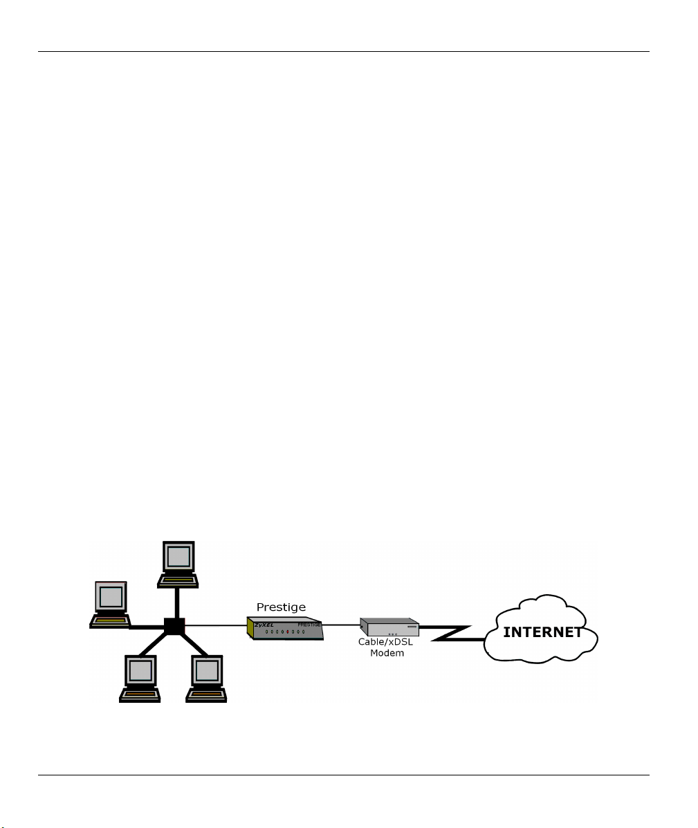
1.3.1 Broadband Internet Access via Cable or DSL Modem
A cable modem or xDSL modem can connect to the Prestige 310 for broadband Internet access via Ethernet
port on the modem. A typical Internet access application is shown next.
Figure 1-1 Internet Access Application
1-4 Getting to Know Your Prestige

Prestige 310 Broadband Sharing Gateway
1.4 Internet Access Configuration Checklist
The following table shows the minimum SMT menu configurations you'll need to make (without changing
the default Prestige values) in order to access the Internet. Also refer to the HTML help on the Web
Configurator.
Table 1-1 Internet Access Configuration Checklist
SMT # FIELD ACTION
1 System Name This field is for identification purposes but because some ISPs check this name you
should enter your computer’s “Computer Name”.
• In Windows 95/98 click Start -> Settings -> Control Panel -> Network. Click
the Identification tab, note the entry for the Computer name field and enter it as
the Prestige System Name.
• In Windows 2000 click Start->Settings->Control Panel and then double-click
System. Click the Network Identification tab and then the Properties button. Note
the entry for the Computer name field and enter it as the Prestige System Name.
• In Windows XP, click start -> My Computer -> View system information and
then click the Computer Name tab. Note the entry in the Full computer name field
and enter it as the Prestige System Name.
2 MAC Address:
Assigned By
4 Encapsulation
PPTP You need to know your login name, password and connection ID/Name. The latter
PPPoE You need to know your login name, password and service name. The latter may not
IP Address
Assignment
Once these key fields have been configured, you should be able to enjoy super-fast Internet access with your
Prestige!
The default is Factory Default, which is the factory assigned default MAC Address.
We recommend you choose IP Address attached on LAN and enter the IP address
of the workstation on the LAN whose MAC you are cloning.
Choose PPPoE if you have a dial-up connection to the Internet (or PPTP if you
reside in France or Austria); otherwise choose Ethernet. Choose from RR-Manager,
RR-Telstra, or RR-Toshiba if your ISP is Time Warner's RoadRunner; otherwise
choose Standard .
may not be obligatory for some ISPs, but if it is you must follow the “c:id” and
“n:name” format.
be obligatory for some ISPs.
If your ISP did not assign you a fixed IP address, select Dynamic, otherwise select
Static and enter the IP address & subnet mask in the IP address and IP Subnet
Mask fields.
Getting to Know Your Prestige 1-5

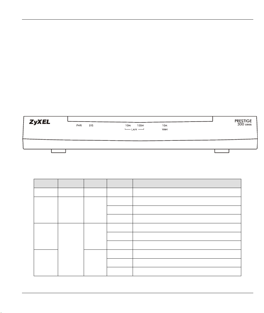
Prestige 310 Broadband Sharing Gateway
Hardware Installation and Initial Setup
This chapter shows you how to connect hardware and perform the initial setup.
2.1 Front Panel LEDs and Rear Panel Ports
2.1.1 Front Panel LEDs
The LEDs on the front panel indicate the operational status of the Prestige.
Figure 2-1 Front Panel LEDs
Chapter 2
Table 2-1 LED Descriptions
LED FUNCTION COLOR STATUS MEANING
PWR Power Green On The Prestige is receiving power.
SYS System
10M LAN
100M LAN
Hardware Installation and Initial Setup 2-1
LAN
Green Off The 10M LAN is not connected.
Orange
Off The system is not ready or failed.
On The system is ready and running.
Flashing The system is rebooting.
On The Prestige is connected to a 10M LAN.
Flashing The 10M LAN is sending/receiving packets.
Off The 100M LAN is not connected.
On The Prestige is connected to a 100Mbps LAN.
Flashing The 100M LAN is sending/receiving packets.
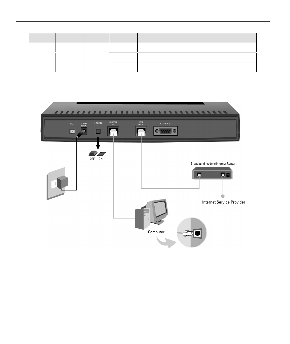
Prestige 310 Broadband Sharing Gateway
LED FUNCTION COLOR STATUS MEANING
WAN WAN Green
Off The WAN Link is not ready, or has failed.
On The WAN Link is ok.
Flashing The 10M WAN link is sending/receiving packets.
2.2 Prestige 310 Rear Panel and Connections
The following figure shows the rear panel of your Prestige 310 and the related connections.
Figure 2-2 Prestige 310 Rear Panel Connections
This section outlines how to connect your Prestige 310 to the LAN and the WAN. If you want to connect a
cable modem, you must connect the coaxial cable from your cable service to the threaded coaxial cable
connector on the back of the cable modem. Connect an xDSL modem to the xDSL wall jack.
2-2 Hardware Installation and Initial Setup

Prestige 310 Broadband Sharing Gateway
2.2.1 Connecting the Console Port
Use terminal emulator software on a computer for configuring your Prestige via console port. Connect the 9pin end of the console cable to the console port of the Prestige and the other end (choice of 9-pin or 25-pin,
depending on your computer) end to a serial port (COM1, COM2 or other COM port) of your computer. You
can use an extension RS-232 cable if the enclosed one is too short. After the initial setup, you can modify the
configuration remotely through Telnet connections.
2.2.2 Connecting the Prestige to the Broadband Modem
Connecting the Prestige to a Cable Modem
Connect the WAN port on the Prestige to the Ethernet port on the cable modem using the cable that came
with your cable modem. The Ethernet port on a cable modem is sometimes labeled "PC" or "Workstation".
Connecting the Prestige to an xDSL Modem
Connect the WAN port on the Prestige to the Ethernet port on the xDSL modem using the cable that came
with your xDSL modem.
2.2.3 Connecting the Prestige to the LAN
When the correct Ethernet cable is correctly connected to the computer or hub,
one of the front panel LAN LEDs will turn on.
For a single computer, connect the 10/100M LAN port on the Prestige to the Network Adapter on the
computer using a straight-through Ethernet cable and push the Uplink button ("on"). If you want to use a
crossover Ethernet cable for this connection, make sure the Uplink button is not pressed (“off”).
If you have more than one computer, you must use an external hub. Connect the 10/100M LAN port on the
Prestige to a port on the hub using a straight-through Ethernet cable and make sure the Uplink button is "off".
If you want to use a crossover Ethernet cable for this connection, make sure the Uplink button is pressed
(“on”).
Table 2-2 Ethernet Cable Requirements and the Uplink Button
UPLINK BUTTON
STATUS
“on” (pressed) straight-through crossover
“off” (not pressed) crossover straight-through
TYPE OF ETHERNET CABLE FOR
CONNECTING THE PRESTIGE TO A …
COMPUTER HUB
Hardware Installation and Initial Setup 2-3

Prestige 310 Broadband Sharing Gateway
2.2.4 Connecting the Power Adapter to your Prestige
Connect one end of the power adapter to the port labeled Power on the rear panel of your Prestige.
To prevent damage to the Prestige, make sure you have the correct power adapter.
See the Power Adapter Specification Appendix for regional specifications.
2.2.5 Grounding the Prestige (Optional)
Ground the Prestige by connecting a grounded wire to the F.G. (Frame Ground) of the Prestige.
2.3 Additional Installation Requirements
1. A computer with an installed Ethernet NIC (Network Interface Card).
2. A computer equipped with communications software called terminal emulation software configured to
the following parameters.
• VT100 terminal emulation.
• 9600 baud.
• No parity, 8 data bits, 1 stop bit, flow control set to none.
3. A cable/xDSL modem and an ISP account.
2.4 Turning on Your Prestige
At this point, you should have connected the Console port, the LAN port, the WAN port and the Power to the
appropriate devices or lines. Plug the power adapter into a power source. The PWR LED turns on. The SYS
LED will come on after the system tests are complete. The WAN LED and one of the LAN LEDs turn on
immediately after the SYS LED turns on, if the proper connections have been made to the LAN and WAN
ports.
2.4.1 Initial Screen
When you turn on your Prestige, it performs several internal tests as well as line initialization.
After the tests, the Prestige asks you to press [ENTER] to continue, as shown next.
2-4 Hardware Installation and Initial Setup

Prestige 310 Broadband Sharing Gateway
Copyright (c) 1994 - 2002 ZyXEL Communications Corp.
initialize ch =0, ethernet address: 00:a0:c5:27:84:52
initialize ch =1, ethernet address: 00:a0:c5:27:84:53
Press ENTER to continue...
Figure 2-3 Initial Screen
2.4.2 Entering the Password
The login screen appears after you press [ENTER], prompting you to enter the password, as shown next.
For your first login, enter the default password "1234"." As you type the password, the screen displays an
"X" for each character you type.
Note that if there is no activity for longer than five minutes after you log in, your Prestige will automatically
log you out and display a blank screen. If you see a blank screen, press [ENTER] to display the login screen
again.
Enter Password : XXXX
Figure 2-4 Password Screen
2.5 Navigating the SMT Interface
The SMT (System Management Terminal) is the interface that you use to configure your Prestige.
Several operations that you should be familiar with before you attempt to modify the configuration are listed
next.
Hardware Installation and Initial Setup 2-5

Prestige 310 Broadband Sharing Gateway
Table 2-3 Main Menu Commands
OPERATION KEYSTROKE DESCRIPTION
Move down to
another menu
Move up to a
previous menu
Move to a “hidden”
menu
Move the cursor [ENTER] or
Entering
information
Required fields
N/A fields <N/A> Some of the fields in the SMT will show a <N/A>. This symbol
Save your
configuration
Exit the SMT Type 99, then press
[ENTER] To move forward to a submenu, type in the number of the desired
submenu and press [ENTER].
[ESC] Press [ESC] to move back to the previous menu.
Press [SPACE
BAR] to change No
to Yes then press
[ENTER].
[UP]/[DOWN] arrow
keys.
Type in or press
[SPACE BAR], then
press [ENTER].
?
<
>
[ENTER] Save your configuration by pressing [ENTER] at the message
[ENTER].
Fields beginning with “Edit” lead to hidden menus and have a
default setting of No. Press [SPACE BAR] once to change No to
Yes, then press [ENTER] to go to the “hidden” menu.
Within a menu, press [ENTER] to move to the next field. You can
also use the [UP]/[DOWN] arrow keys to move to the previous
and the next field, respectively.
You need to fill in two types of fields. The first requires you to type
in the appropriate information. The second allows you to cycle
through the available choices by pressing [SPACE BAR].
All fields with the symbol <?> must be filled in order to be able to
save the new configuration.
refers to an option that is Not Applicable.
“Press ENTER to confirm or ESC to cancel”. Saving the data on
the screen will take you, in most cases to the previous menu.
Type 99 at the main menu prompt and press [ENTER] to exit the
SMT interface.
2.5.1 Main Menu
After you enter the password, the SMT displays the Main Menu, as shown next.
2-6 Hardware Installation and Initial Setup

Prestige 310 Broadband Sharing Gateway
Copyright (c) 1994 - 2002 ZyXEL Communications Corp
Prestige 310 Main Menu
Getting Started Advanced Management
1. General Setup 21. Filter Set Configuration
2. WAN Setup 22. SNMP Configuration
3. LAN Setup 23. System Password
4. Internet Access Setup 24. System Maintenance
Advanced Applications 26. Schedule Setup
11. Remote Node Setup
12. Static Routing Setup
15. NAT Setup
99. Exit
Enter Menu Selection Number:
Figure 2-5 Prestige 310 Main Menu
2.5.2 System Management Terminal Interface Summary
Table 2-4 Main Menu Summary
NO. MENU TITLE FUNCTION
1 General Setup Use this menu to set up routing/bridging and general information.
2 WAN Setup Use this menu to clone a MAC address from a computer on your LAN.
3 LAN Setup Use this menu to configure LAN DHCP and TCP/IP settings as well as
apply LAN filters.
4 Internet Access Setup
11 Remote Node Setup Use this menu to configure detailed remote node settings (your ISP is
12 Static Routing Setup Configure static routes for bridging and IP in this menu.
15 NAT Setup Use this menu to configure Network Address Translation.
21 Filter Set Configuration Use this menu to provide security via filters.
22 SNMP Configuration Use this menu to configure SNMP-related parameters.
23 System Password Change your password in this menu (recommended).
24 System Maintenance
26 Schedule Setup Use this menu to schedule outgoing calls.
99 Exit Use this menu to exit (necessary for remote configuration).
Configure your Internet Access setup (Internet address, gateway, login,
etc.) with this menu.
also a remote node) as well as apply WAN filters.
From displaying system status to uploading firmware, this menu provides
comprehensive system maintenance.
Hardware Installation and Initial Setup 2-7

Prestige 310 Broadband Sharing Gateway
2.5.3 SMT Menus at a Glance
Figure 2-6 Getting Started and Advanced Application SMT Menus
2-8 Hardware Installation and Initial Setup

Prestige 310 Broadband Sharing Gateway
Figure 2-7 Advanced Management SMT Menus
Hardware Installation and Initial Setup 2-9

Prestige 310 Broadband Sharing Gateway
2.6 Changing the System Password
Change the default system password by following the steps shown next.
Step 1. Enter 23 in the main menu to open Menu 23 — System Password as shown next.
Menu 23 - System Password
Old Password= ?
New Password= ?
Retype to confirm= ?
Enter here to CONFIRM or ESC to CANCEL:
Figure 2-8 Menu 23 — System Password
Step 2. Type your existing password in the Old Password field and press [ENTER].
Step 3. Type your new system password in the New Password field and press [ENTER].
Step 4. Re-type your new system password for confirmation in the Retype to confirm field and press
[ENTER].
Note that as you type a password, the screen displays an "X" for each character you type.
2.6.1 Resetting the Prestige
If you have forgotten your password or cannot access the SMT menus you will need to reinstall the
configuration file. Uploading the configuration file replaces the current configuration file with the default
configuration file, you will lose all configurations that you had before and the speed of the console port will
be reset to the default of 9600bps with 8 data bit, no parity and 1 stop bit (8n1). The password will be reset to
the default of “1234”.
Turn off the Prestige and begin a terminal emulation software session with the default console port settings.
Turn on the Prestige again. When you see the message "Press Any key to enter Debug Mode within 3
seconds", press any key to enter debug mode. You should already have downloaded the correct file from
your nearest ZyXEL FTP site. Refer to the Firmware and Configuration Maintenance chapter for more
information on how to transfer the configuration file to your Prestige.
2-10 Hardware Installation and Initial Setup

Prestige 310 Broadband Sharing Gateway
2.7 General Setup
Menu 1 - General Setup contains administrative and system-related information (shown next). The System
Name field is for identification purposes. However, because some ISPs check this name you should enter
your computer's "Computer Name".
• In Windows 95/98 click Start -> Settings -> Control Panel -> Network. Click the Identification
tab, note the entry for the Computer name field and enter it as the Prestige System Name.
• In Windows 2000 click Start->Settings->Control Panel and then double-click System. Click the
Network Identification tab and then the Properties button. Note the entry for the Computer name
field and enter it as the Prestige System Name.
• In Windows XP, click start -> My Computer -> View system information and then click the
Computer Name tab. Note the entry in the Full computer name field and enter it as the Prestige
System Name.
The Domain Name entry is what is propagated to the DHCP clients on the LAN. If you leave this blank, the
domain name obtained by DHCP from the ISP is used. While you must enter the host name (System Name)
on each individual computer, the domain name can be assigned from the Prestige via DHCP.
2.7.1 Dynamic DNS
Dynamic DNS (Domain Name System) allows you to update your current dynamic IP address with one or
many dynamic DNS services so that anyone can contact you (in NetMeeting, CU-SeeMe or other services).
You can also access your FTP server or Web site on your own computer using a DNS-like address (for
example, myhost.dhs.org, where myhost is a name of your choice) which will never change instead of using
an IP address that changes each time you reconnect. Your friends or relatives will always be able to call you
even if they don't know your IP address.
First of all, you need to have registered a dynamic DNS account with www.dyndns.org. This is for people
with a dynamic IP from their ISP or DHCP server that would still like to have a DNS name.
To use this service, you must register with the Dynamic DNS service provider. The Dynamic DNS service
provider will give you a password or key. The Prestige supports www.dyndns.org. You can apply to this
service provider for Dynamic DNS service.
DYNDNS Wildcard
Enabling the wildcard feature for your host causes *.yourhost.dyndns.org to be aliased to the same IP address
as yourhost.dyndns.org. This feature is useful if you want to be able to use, for example,
www.yourhost.dyndns.org and still reach your hostname.
Hardware Installation and Initial Setup 2-11

Prestige 310 Broadband Sharing Gateway
2.7.2 Procedure For Configuring Menu 1
Step 1. Enter 1 in the Main Menu to open Menu 1 - General Setup (shown next).
Menu 1 - General Setup
System Name= xxx
Domain Name=zyxel.com.tw
Edit Dynamic DNS= No
Press ENTER to Confirm or ESC to Cancel:
Figure 2-9 Menu 1 — General Setup
Step 2. Fill in the required fields. Refer to the table shown next for more information about these fields.
Table 2-5 General Setup Menu Fields
FIELD DESCRIPTION EXAMPLE
System Name Choose a descriptive name for identification purposes. It is
recommended you enter your computer’s “Computer name” in this
field. This name can be up to 30 alphanumeric characters long.
Spaces are not allowed, but dashes “-” and underscores "_" are
accepted.
Domain Name Enter the domain name (if you know it) here. If you leave this field
blank, the ISP may assign a domain name via DHCP. You can go to
menu 24.8 and type "sys domainname" to see the current domain
name used by your gateway.
If you want to clear this field just press the [SPACE BAR]. The
domain name entered by you is given priority over the ISP assigned
domain name.
Edit Dynamic
DNS
When you have completed this menu, press [ENTER] at the prompt “Press ENTER to Confirm…” to
save your configuration, or press [ESC] at any time to cancel.
Press the [SPACE BAR] to select Yes or No (default). Select Yes to
configure Menu 1.1 — Configure Dynamic DNS (discussed next).
P310
zyxel.com.tw
No
2.7.3 Configuring Dynamic DNS
To configure Dynamic DNS, go to Menu 1 — General Setup and press select Yes in the Edit Dynamic
DNS field. Press [ENTER] to display Menu 1.1— Configure Dynamic DNS as shown next.
2-12 Hardware Installation and Initial Setup

Prestige 310 Broadband Sharing Gateway
Menu 1.1 - Configure Dynamic DNS
Service Provider = WWW.DynDNS.ORG
Active= Yes
DDNSType= DynamicDNS
Host= me.ddns.org
EMAIL= mail@mailserver
USER= username
Password= *********
Enable Wildcard= No
Offline= N/A
Figure 2-10 Configure Dynamic DNS
Follow the instructions in the next table to configure Dynamic DNS parameters.
Table 2-6 Configure Dynamic DNS Menu Fields
FIELD DESCRIPTION EXAMPLE
Service Provider This is the name of your Dynamic DNS service provider. WWW.DynDNS.ORG
(default)
Active
DDNS Type
Press [SPACE BAR] to select Yes and then press [ENTER] to
make dynamic DNS active.
Press [SPACE BAR] and then [ENTER] to select DynamicDNS
if you have a dynamic IP address(es). Select StaticDNS if you
have a static IP address(s).
Select CustomDNS to have dyns.org provide DNS service for
a domain name that you already have from a source other than
dyndns.org.
At the time of writing, dyndns.org provides the basic
DynamicDNS and StaticDNS services along with a limited
number of hostnames for free, but charges a fee for
CustomDNS. See www.dyndns.org for details.
Yes
DynamicDNS
(defautl)
Host Enter the domain name assigned to your Prestige by your
me.dyndns.org
Dynamic DNS provider.
EMAIL Enter your e-mail address. mail@mailserver
USER Enter your user name.
Password Enter the password assigned to you.
Enable Wildcard Your Prestige supports DYNDNS Wildcard. Press [SPACE
No
BAR] and then [ENTER] to select Yes or No This field is N/A
when you choose DDNS client as your service provider.
Offline
This field is only available when CustomDNS is selected in the Yes
Hardware Installation and Initial Setup 2-13
Prestige 310 Broadband Sharing Gateway
FIELD DESCRIPTION EXAMPLE
DDNS Type field. Press [SPACE BAR] and then [ENTER] to
select Yes. When Yes is selected, traffic is redirected to a URL
that you have previously specified (see www.dyndns.org for
details).
When you have completed this menu, press [ENTER] at the prompt “Press ENTER to Confirm…” to save
your configuration, or press [ESC] at any time to cancel.
If you have a private WAN IP address, then you can not use Dynamic DNS.
2.8 WAN Setup
This section describes how to configure the WAN using Menu 2 - WAN Setup. From the main menu, enter 2
to display menu 2.
ZyXEL recommends you configure this menu even if your ISP does not require
MAC address athentication.
Menu 2 - WAN Setup
MAC Address:
Assigned By=IP address attached on LAN
IP Address= 192.168.1.33
Press ENTER to Confirm or ESC to Cancel:
Press Space Bar to Toggle
Figure 2-11 Menu 2 — WAN Setup
This screen allows you to configure the WAN port's MAC Address by either using the factory default or
cloning the MAC address from a workstation on your LAN. Once it is successfully configured, the address
will be copied to the rom file (ZyNOS configuration file). It will not change unless you change the setting in
menu 2 or upload a different rom file.
The following table contains instructions on how to configure your WAN setup.
2-14 Hardware Installation and Initial Setup

Prestige 310 Broadband Sharing Gateway
Table 2-7 WAN Setup Menu Fields
FIELD DESCRIPTION EXAMPLE
MAC Address
Assigned By Press the [SPACE BAR] to choose one of two methods to assign a
MAC Address. Choose Factory default to select the factory assigned
default MAC Address. Choose IP Address attached on LAN to use
the MAC Address of that workstation whose IP you give in the
following field.
IP Address
When you have completed this menu, press [ENTER] at the prompt “Press ENTER to Confirm…” to save
your configuration, or press [ESC] at any time to cancel.
This field is applicable only if you choose the IP Address attached
on LAN method in the Assigned By field above. Enter the IP
address of the workstation on the LAN whose MAC you are cloning.
IP Address
attached on
LAN
192.168.1.33
Your Prestige WAN Port is always set at half-duplex mode as most cable modems only support half-duplex
mode. If your cable modem supports full-duplex mode, then you will be able to manually set it at half-duplex
mode. If the Prestige is set at half-duplex mode and the cable modem is set at full-duplex mode, then the
WAN port will not function properly.
Your Prestige supports full duplex mode on the LAN side.
2.9 LAN Setup
This section describes how to configure the LAN using Menu 3 — LAN Setup. From the main menu, enter
3 to display menu 3 (shown next).
Menu 3 - LAN Setup
1. LAN Port Filter Setup
2. TCP/IP and DHCP Setup
Enter Menu Selection Number:
Figure 2-12 Menu 3 — LAN Setup
Hardware Installation and Initial Setup 2-15

Prestige 310 Broadband Sharing Gateway
2.9.1 LAN Port Filter Setup
This menu allows you to specify the filter sets that you wish to apply to the LAN traffic. You seldom need to
filter the LAN traffic, however, the filter sets may be useful to block certain packets, reduce traffic and
prevent security breaches.
Menu 3.1 – LAN Port Filter Setup
Input Filter Sets:
protocol filters= 2
device filters=
Output Filter Sets:
protocol filters=
device filters=
Press ENTER to Confirm or ESC to Cancel:
Figure 2-13 Menu 3.1 - LAN Port Filter Setup
Menu 3.2 is discussed in the next part of this User's Guide. Please read on.
2-16 Hardware Installation and Initial Setup

Prestige 310 Broadband Sharing Gateway
Chapter 3
Internet Access
This chapter shows you how to configure the LAN as well as the WAN of your Prestige for Internet
access.
3.1 TCP/IP and DHCP for LAN
The Prestige has built-in DHCP server capability that assigns IP addresses and DNS servers to systems that
support DHCP client capability.
3.1.1 Factory LAN Defaults
The LAN parameters of the Prestige are preset in the factory with the following values:
1. IP address of 192.168.1.1 with subnet mask of 255.255.255.0 (24 bits)
2. DHCP server enabled with 32 client IP addresses starting from 192.168.1.33.
These parameters should work for the majority of installations. If your ISP gives you explicit DNS server
address(es), skip to the DNS Server Address section to see how to enter the DNS server address(es).
3.1.2 DHCP Configuration
DHCP (Dynamic Host Configuration Protocol, RFC 2131 and RFC 2132) allows individual clients to obtain
TCP/IP configuration at start-up from a server. You can configure the Prestige as a DHCP server or disable
it. When configured as a server, the Prestige provides the TCP/IP configuration for the clients. If set to
None, DHCP service will be disabled and you must have another DHCP server on your LAN, or else the
workstation must be manually configured.
The Prestige can also act as a surrogate DHCP server (DHCP Relay) where it relays IP address assignment
from the actual real DHCP server to the clients.
IP Pool Setup
The Prestige is pre-configured with a pool of 32 IP addresses starting from 192.168.1.33 to 192.168.1.64.
This configuration leaves 31 IP addresses (excluding the Prestige itself) in the lower range for other server
computers, for example, server for mail, FTP, Telnet, web, etc., that you may have.
Internet Access 3-1

Prestige 310 Broadband Sharing Gateway
DNS Server Address
Use DNS (Domain Name System) to map a domain name to its corresponding IP address and vice versa, for
example, the IP address of www.zyxel.com is 204.217.0.2. The DNS server is extremely important because
without it, you must know the IP address of a computer before you can access it.
There are two ways that an ISP disseminates the DNS server addresses.
1. The ISP tells you the DNS server addresses, usually in the form of an information sheet, when you sign
up. If your ISP gives you DNS server addresses, enter them in the DNS Server fields in DHCP Setup.
2. Leave the DNS Server fields in DHCP Setup blank (for example 0.0.0.0). The Prestige acts as a DNS
proxy when this field is blank.
Table 3-1 Example of Network Properties for LAN Servers with Fixed IP Addresses
Choose an IP address
Subnet mask 255.255.255.0
Gateway (or default route) 192.168.1.1 (Prestige LAN IP)
192.168.1.2 - 192.168.1.32; 192.168.1.65 - 192.168.1.254.
3.1.3 IP Address and Subnet Mask
Similar to the way houses on a street share a common street name, so too do computers on a LAN share one
common network number.
Where you obtain your network number depends on your particular situation. If the ISP or your network
administrator assigns you a block of registered IP addresses, follow their instructions in selecting the IP
addresses and the subnet mask.
If the ISP did not explicitly give you an IP network number, then most likely you have a single user account
and the ISP will assign you a dynamic IP address when the connection is established. If this is the case, it is
recommended that you select a network number from 192.168.0.0 to 192.168.255.0 and you must enable the
Network Address Translation (NAT) feature of the Prestige. The Internet Assigned Number Authority
(IANA) reserved this block of addresses specifically for private use; please do not use any other number
unless you are told otherwise. Let's say you select 192.168.1.0 as the network number; which covers 254
individual addresses, from 192.168.1.1 to 192.168.1.254 (zero and 255 are reserved). In other words, the first
three numbers specify the network number while the last number identifies an individual workstation on that
network.
Once you have decided on the network number, pick an IP address that is easy to remember, for example,
192.168.1.1, for your Prestige, but make sure that no other device on your network is using that IP.
The subnet mask specifies the network number portion of an IP address. Your Prestige will compute the
subnet mask automatically based on the IP address that you entered. You don't need to change the subnet
mask computed by the Prestige unless you are instructed to do otherwise.
3-2 Internet Access

Prestige 310 Broadband Sharing Gateway
3.1.4 Private IP Addresses
Every computer on the Internet must have a unique IP address. If your networks are isolated from the
Internet, for example, only between your two branch offices, you can assign any IP addresses to the hosts
without problems. However, the Internet Assigned Numbers Authority (IANA) has reserved the following
three blocks of IP addresses specifically for private networks:
Table 3-2 Private IP Address Ranges
10.0.0.0 — 10.255.255.255
172.16.0.0 — 172.31.255.255
192.168.0.0 — 192.168.255.255
You can obtain your IP address from the IANA, from an ISP or have it assigned by a private network. If you
belong to a small organization and your Internet access is through an ISP, the ISP can provide you with the
Internet addresses for your local networks. On the other hand, if you are part of a much larger organization,
you should consult your network administrator for the appropriate IP addresses.
Regardless of your particular situation, do not create an arbitrary IP address;
always follow the guidelines above. For more information on address assignment,
please refer to RFC 1597, Address Allocation for Private Internets and RFC 1466,
Guidelines for Management of IP Address Space.
3.1.5 RIP Setup
RIP (Routing Information Protocol, RFC1058 and RFC 1389) allows a router to exchange routing
information with other routers. The RIP Direction field controls the sending and receiving of RIP packets.
When set to Both or Out Only, the Prestige will broadcast its routing table periodically. When set to Both
or In Only, it will incorporate the RIP information that it receives; when set to None, it will not send any
RIP packets and will ignore any RIP packets received.
The Version field controls the format and the broadcasting method of the RIP packets that the Prestige sends
(it recognizes both formats when receiving). RIP-1 is universally supported; but RIP-2 carries more
information. RIP-1 is probably adequate for most networks, unless you have an unusual network topology.
Both RIP-2B and RIP-2M sends the routing data in RIP-2 format; the difference being that RIP-2B uses
subnet broadcasting while RIP-2M uses multicasting. Multicasting can reduce the load on non-router
machines since they generally do not listen to the RIP multicast address and so will not receive the RIP
packets. However, if one router uses multicasting, then all routers on your network must use multicasting,
also.
By default, RIP Direction is set to Both and the Version set to RIP-1.
Internet Access 3-3

Prestige 310 Broadband Sharing Gateway
3.1.6 IP Multicast
Traditionally, IP packets are transmitted in one of either two ways - Unicast (1 sender - 1 recipient) or
Broadcast (1 sender - everybody on the network). Multicast delivers IP packets to a group of hosts on the
network - not everybody and not just 1.
IGMP (Internet Group Multicast Protocol) is a session-layer protocol used to establish membership in a
Multicast group - it is not used to carry user data. IGMP version 2 (RFC 2236) is an improvement over
version 1 (RFC 1112) but IGMP version 1 is still in wide use. If you would like to read more detailed
information about interoperability between IGMP version 2 and version 1, please see sections 4 and 5 of
RFC 2236. The class D IP address is used to identify host groups and can be in the range 224.0.0.0 to
239.255.255.255. The address 224.0.0.0 is not assigned to any group and is used by IP multicast computers.
The address 224.0.0.1 is used for query messages and is assigned to the permanent group of all IP hosts
(including gateways). All hosts must join the 224.0.0.1 group in order to participate in IGMP. The address
224.0.0.2 is assigned to the multicast routers group.
The Prestige supports both IGMP version 1 (IGMP-v1) and IGMP version 2 (IGMP-v2). At start up, the
Prestige queries all directly connected networks to gather group membership. After that, the Prestige
periodically updates this information. IP Multicasting can be enabled/disabled on the Prestige LAN and/or
WAN interfaces using menus 3.2 (LAN) and 11.3 (WAN). Select None to disable IP Multicasting on these
interfaces.
3.1.7 IP Alias
IP Alias allows you to partition a physical network into different logical networks over the same Ethernet
interface. The Prestige supports three logical LAN interfaces via its single physical Ethernet interface with
the Prestige itself as the gateway for each LAN network.
Figure 3-1 Physical Network Figure 3-2 Partitioned Logical Networks
3-4 Internet Access

Prestige 310 Broadband Sharing Gateway
Use menu 3.2.1 to configure IP Alias on your Prestige.
3.2 TCP/IP and DHCP Ethernet Setup
From the Main Menu, enter 3 to open Menu 3 — LAN Setup (10/100 Mbps Ethernet) to configure TCP/IP
(RFC 1155) and DHCP Ethernet setup.
Menu 3 – LAN Setup
1. LAN Port Filter Setup
2. TCP/IP and DHCP Setup
Enter Menu Selection Number:
Figure 3-3 Menu 3 — LAN Setup (10/100 Mbps Ethernet)
To edit the TCP/IP and DHCP configuration, enter 2 to display Menu 3.2 — TCP/IP and DHCP Ethernet
Setup as shown next.
Menu 3.2 - TCP/IP and DHCP Ethernet Setup
DHCP= Server
Configuration:
Client IP Pool Starting Address= 192.168.1.33
Size of Client IP Pool= 32
Primary DNS Server= 0.0.0.0
Secondary DNS Server= 0.0.0.0
DHCP Server Address = N/A
TCP/IP Setup:
IP Address= 192.68.1.1
IP Subnet Mask= 255.255.255.0
RIP Direction= Both
Multicast= None
Edit IP Alias= No
Press ENTER to Confirm or ESC to Cancel:
Press Space Bar to Toggle.
Version= RIP-1
First address
in the IP
Pool.
Size of the IP
Pool.
IP addresses of
the DNS
servers.
This is the IP
address of the
.
Prestige
Figure 3-4 Menu 3.2 — TCP/IP and DHCP Ethernet Setup
Internet Access 3-5

Prestige 310 Broadband Sharing Gateway
Follow the instructions in the following table on how to configure the DHCP fields.
Table 3-3 LAN DHCP Setup Menu Fields
FIELD DESCRIPTION EXAMPLE
DHCP
Configuration:
Client IP Pool Starting
Address
Size of Client IP Pool This field specifies the size, or count, of the IP address pool. 32
Primary DNS Server
Secondary DNS
Server
This field enables/disables the DHCP server. If it is set to Server,
your Prestige will act as a DHCP server. If set to None, DHCP
service will be disabled and you must have another DHCP sever
on your LAN, or else the workstation must be manually configured.
When DHCP is set to Server, the following four items need to be
set. The Prestige can now also act as a surrogate DHCP server
(Relay) where it relays IP address assignment from the actual real
DHCP server to the clients.
This field specifies the first of the contiguous addresses in the IP
address pool.
Enter the IP addresses of the DNS servers. The DNS servers are
passed to the DHCP clients along with the IP address and the
subnet mask. Leave these entries at 0.0.0.0 if they are provided by
a WAN DHCP server.
Server
(default)
192.168.1.33
DHCP Server Address The Prestige acts as a surrogate DHCP server when you select
Relay from the DHCP field.
This field is N/A when the DHCP field is Server or None.
N/A
Follow the instructions in the following table on how to configure the TCP/IP parameters for the LAN port.
Table 3-4 LAN TCP/IP Setup Menu Fields
FIELD DESCRIPTION EXAMPLE
TCP/IP Setup:
IP Address Enter the IP address of your Prestige in dotted decimal notation 192.168.1.1
(default)
IP Subnet Mask Your Prestige will automatically calculate the subnet mask based on
the IP address that you assign. Unless you are implementing
subnetting, use the subnet mask computed by the Prestige
RIP Direction Press the [SPACE BAR] to select the RIP direction.
Options are Both, In Only, Out Only or None.
255.255.255.0
Both
(default)
3-6 Internet Access

Prestige 310 Broadband Sharing Gateway
p
FIELD DESCRIPTION EXAMPLE
Version Press the [SPACE BAR] to select the RIP version.
Options are RIP-1, RIP-2B or RIP-2M.
Multicast IGMP (Internet Group Multicast Protocol) is a session-layer protocol
RIP-1
(default)
None
used to establish membership in a Multicast group. The Prestige
supports both IGMP version 1 (IGMP-v1) and IGMP-v2. Press the
[SPACE BAR] to enable IP Multicasting or select None (default) to
disable it.
Edit IP Alias The Prestige supports three logical LAN interfaces via its single
Yes
physical Ethernet interface with the Prestige itself as the gateway for
each LAN network. Press the [SPACE BAR] to select Yes, then
press [ENTER] to display menu 3.2.1
When you have completed this menu, press [ENTER] at the prompt [Press ENTER to Confirm…] to save
your configuration, or press [ESC] at any time to cancel.
3.2.1 IP Alias Setup
Use menu 3.2 to configure the first network and move the cursor to the Edit IP Alias field and press
[SPACE BAR] to choose Yes and press [ENTER] to configure the second and third network.
Pressing [ENTER] opens Menu 3.2.1 — IP Alias Setup, as shown next.
Menu 3.2.1 - IP Alias Setup
IP Alias 1= No
IP Address= N/A
IP Subnet Mask= N/A
RIP Direction= N/A
Version= N/A
Incoming protocol filters= N/A
Outgoing protocol filters= N/A
IP Alias 2= No
IP Address= N/A
IP Subnet Mask= N/A
RIP Direction= N/A
Version= N/A
Incoming protocol filters= N/A
Outgoing protocol filters= N/A
Enter here to CONFIRM or ESC to CANCEL:
Press S
ace Bar to Toggle.
Figure 3-5 Menu 3.2.1 — IP Alias Setup
Follow the instructions in the following table to configure IP Alias parameters.
Internet Access 3-7

Prestige 310 Broadband Sharing Gateway
Table 3-5 IP Alias Setup Menu Fields
FIELD DESCRIPTION EXAMPLE
IP Alias
IP Address Enter the IP address of your Prestige in dotted decimal notation 192.168.2.1
IP Subnet Mask Your Prestige will automatically calculate the subnet mask based on
RIP Direction Press the [SPACE BAR] to select the RIP direction.
Version Press the [SPACE BAR] to select the RIP version.
Choose Yes to configure the LAN network for the Prestige. Yes
255.255.255.0
the IP address that you assign. Unless you are implementing
subnetting, use the subnet mask computed by the Prestige.
None
Options are None, Both, In Only or Out Only.
RIP-1
Options are RIP-1, RIP-2B or RIP-2M.
Incoming
Protocol Filters
Outgoing
Protocol Filters
When you have completed this menu, press [ENTER] at the prompt [Press ENTER to Confirm…] to save
your configuration, or press [ESC] at any time to cancel.
Enter the filter set(s) you wish to apply to the incoming traffic
between this node and the Prestige.
Enter the filter set(s) you wish to apply to the outgoing traffic between
this node and the Prestige.
3.3 Internet Access Setup
You will see three different menu 4 screens depending on whether you chose Ethernet, PPTP or PPPoE
encapsulation.
In the Encapsulation field in menu 4, choose:
• Ethernet when the WAN port is used as a regular Ethernet.
• PPTP or PPPoE if you have a dial-up connection to the Internet.
3.3.1 Ethernet Encapsulation
You must choose the Ethernet option when the WAN port is used as a regular Ethernet. If you choose
Ethernet in menu 4 you will see the next screen.
3-8 Internet Access

Prestige 310 Broadband Sharing Gateway
Menu 4 - Internet Access Setup
ISP's Name= ChangeMe
Encapsulation= Ethernet
Service Type= Standard
My Login= N/A
My Password= N/A
Login Server IP= N/A
IP Address Assignment= Dynamic
IP Address= N/A
IP Subnet Mask= N/A
Gateway IP Address= N/A
Network Address Translation = SUA Only
Press ENTER to Confirm or ESC to Cancel:
Figure 3-6 Internet Access Setup (Ethernet)
The following table describes this screen.
Table 3-6 Internet Access Setup Menu Fields
FIELD DESCRIPTION
ISP’s Name Enter the name of your Internet Service Provider, for example, myISP. This
information is for identification purposes only.
Encapsulation
Service Type This is applicable only when you choose Ethernet as your encapsulation
Note: xDSL users must choose the Standard option only. The Server IP, My Login IP and My
Password" fields are not applicable in this case.
Press the [SPACE BAR] and the press [ENTER] to choose Ethernet. The
encapsulation method influences your choices for IP Address.
method. Press the [SPACE BAR] to select Standard, RR-Toshiba
(RoadRunner Toshiba authentication method), RR-Manager (RoadRunner
Manager authentication method) or RR-Telstra (RoadRunner Telstra
authentication method). Choose a RoadRunner flavor if your ISP is Time
Warner's RoadRunner; otherwise choose Standard.
My Login Enter the login name given to you by your ISP.
My Password Enter the password associated with the login name above.
Login Server IP The Prestige will find the RoadRunner Server IP if this field is left blank. If it
does not, then you must enter the authentication server IP address.
IP Address Assignment
If your ISP did not assign you a fixed IP address, select Dynamic, otherwise
Internet Access 3-9

Prestige 310 Broadband Sharing Gateway
FIELD DESCRIPTION
select Static and enter the IP address & subnet mask in the following fields.
IP Address Enter the (fixed) IP address assigned to you by your ISP (Static IP Address
Assignment is selected in the previous field).
IP Subnet Mask Enter the subnet mask associated with your static IP.
Gateway IP Address Enter the gateway IP address associated with your static IP.
Network Address
Translation
Once you have finished configuring a rule in this menu, press [ENTER] at the message “Press ENTER to
Confirm…” to save your configuration, or press [ESC] to cancel.
Refer to the following chapter for a more detailed discussion on the Single
User Account and NAT. Options are SUA only, Full Feature or None.
3.3.2 PPTP Encapsulation
Point-to-Point Tunneling Protocol (PPTP) is a network protocol that enables transfer of data from a remote
client to a private server, creating a Virtual Private Network (VPN) using TCP/IP-based networks.
PPTP supports on-demand, multi-protocol, and virtual private networking over public networks, such as the
Internet.
The P310 supports one PPTP server connection at any given time.
3.3.3 Configure PPTP Client
To configure a PPTP client, you must configure My Login and Password fields for PPP connection and
PPTP parameters for PPTP connection.
After configuring the User Name and Password for PPP connection, press [SPACE BAR] in the
Encapsulation field in Menu 4 —Internet Access Setup to choose PPTP as your encapsulation option.
If you choose PPTP in menu 4 you will see the next screen.
3-10 Internet Access

Prestige 310 Broadband Sharing Gateway
Menu 4 - Internet Access Setup
ISP's Name= ChangeMe
Encapsulation= PPTP
Service Type= N/A
My Login= username
My Password= ******
Idle Timeout= 300
IP Address Assignment= Dynamic
IP Address= N/A
IP Subnet Mask= N/A
Gateway IP Address=N/A
Network Address Translation = SUA Only
Press ENTER to Confirm or ESC to Cancel:
Figure 3-7 Internet Access Setup (PPTP)
The following table contains instructions about the new fields when you choose PPTP in the Encapsulation
field in menu 4.
Table 3-7 New Fields in Menu 4 (PPTP) Screen
FIELD DESCRIPTION EXAMPLE
Encapsulation Press the [SPACE BAR] and then press [ENTER] to choose
PPTP
PPTP. The encapsulation method influences your choices for
IP Address.
Idle Timeout This value specifies the time in seconds that elapses before
the Prestige automatically disconnects from the PPTP server.
300
(default)
Once you have finished configuring a rule in this menu, press [ENTER] at the message “Press
ENTER to Confirm…” to save your configuration, or press [ESC] to cancel.
3.3.4 PPPoE Encapsulation
The Prestige supports PPPoE (Point-to-Point Protocol over Ethernet). You can use PPPoE encapsulation only
when you're using the Prestige with an xDSL modem as the WAN device.
PPPoE is an IETF Draft standard specifying how a host personal computer interacts with a broadband
modem (i.e. xDSL, cable, wireless, etc.) to achieve access to high-speed data networks. It preserves the
existing Microsoft Dial-Up Networking experience and requires no new learning or procedures.
For the service provider, PPPoE offers an access and authentication method that works with existing access
control systems (for example, Radius). For the user, PPPoE provides a login and authentication method that
the existing Microsoft Dial-Up Networking software can activate, and therefore requires no new learning or
procedures for Windows users.
Internet Access 3-11

Prestige 310 Broadband Sharing Gateway
One of the benefits of PPPoE is the ability to let end users access one of multiple network services, a function
known as dynamic service selection. This enables the service provider to easily create and offer new IP
services for specific users.
Operationally, PPPoE saves significant effort for both the end user and ISP/carrier, as it requires no specific
configuration of the broadband modem at the customer site.
By implementing PPPoE directly on the Prestige (rather than individual computers), the computers on the
LAN do not need PPPoE software installed, since the Prestige does that part of the task. Furthermore, with
NAT, all of the LAN's computers will have access.
If you enable PPPoE in menu 4, you will see the next screen. For more information on PPPoE, please refer to
the PPPoE Appendix.
Menu 4 - Internet Access Setup
ISP's Name= ChangeMe
Encapsulation= PPPoE
Service Type= N/A
My Login=
My Password= ********
Idle Timeout= 300
IP Address Assignment= Dynamic
IP Address= N/A
IP Subnet Mask= N/A
Gateway IP Address= N/A
Network Address Translation = SUA Only
Press ENTER to Confirm or ESC to Cancel:
Figure 3-8 Internet Access (PPPoE)
Table 3-8 New Fields in Menu 4 (PPPoE) Screen
FIELD DESCRIPTION EXAMPLE
Encapsulation Press the [SPACE BAR] and then press [ENTER] to choose
PPPoE
PPPoE. The encapsulation method influences your choices for
IP Address.
Idle Timeout This value specifies the time in seconds that elapses before the
Prestige automatically disconnects from the PPPoE server.
300
(default)
3-12 Internet Access

Prestige 310 Broadband Sharing Gateway
3.4 Internet Test Setup
After configuring the menu 4 fields when you press [ENTER] to confirm you will see the message, " Do you
wish to perform the Internet Setup Test [y/n]:" if you have chosen PPTP or PPPoE as your encapsulation
method. Enter “y” to test your setup. An example of Internet Setup Test is shown next.
Start dialing for node <ChangeMe>...
### Hit any key to continue.###
$$$ DIALING dev=a ch=0..........
$$$ OUTGOING-CALL phone()
$$$ PPTP: Start tunnel setup, send SCCRQ
$$$ PPTP: OCRQ sent
$$$ CALL CONNECT speed<10000000> type<10> chan<0>
$$$ LCP opened
$$$ CHAP login to remote OK
$$$ IPCP negotiation started
$$$ CCP stopped
$$$ BACP stopped
$$$ IPCP neg' Primary DNS 202.xxx.xxx.x
$$$ IPCP opened
Figure 3-9 Internet Setup Test Example
3.5 Basic Setup Complete
Well done! You have successfully connected, installed and set up your Prestige to operate on your network
and access the Internet.
Internet Access 3-13

Advanced Applications
PPaarrtt IIII:
:
Advanced Applications
This section describes the advanced applications of your Prestige, such as Remote Node Setup, IP
Static Route Setup and NAT.
II

Prestige 310 Broadband Sharing Gateway
Chapter 4
Remote Node Setup
This chapter shows you how to configure a remote node.
A remote node is required for placing calls to a remote gateway. A remote node represents both the remote
gateway and the network behind it across a WAN connection. Note that when you use menu 4 to set up
Internet access, you are actually configuring a remote node. We will show you how to configure the
following menus:
• Menu 11.1 — Remote Node Profile
• Menu 11.3 — Remote Node Network Layer Options
• Menu 11.5 — Remote Node Filter.
4.1 Remote Node Profile
From the main menu, enter 11 to display Menu 11.1 — Remote Node Profile. There are three variations of
this menu depending on whether you choose Ethernet Encapsulation, PPTP or PPPoE Encapsulation.
4.1.1 Ethernet Encapsulation
Choose the Ethernet option when the WAN port is used as a regular Ethernet. The first menu 11.1 screen
you see is for Ethernet Encapsulation shown next.
Menu 11.1 - Remote Node Profile
Rem Node Name= ChangeMe Route= IP
Active= Yes
Encapsulation= Ethernet Edit IP= No
Service Type= Standard Session Options:
Service Name= N/A Edit Filter Sets= No
Outgoing:
My Login= N/A
My Password= N/A
Server IP= CHAP/PAP
Press ENTER to Confirm or ESC to Cancel.
Figure 4-1 Remote Node Profile for Ethernet Encapsulation
Remote Node Setup 4-1

Prestige 310 Broadband Sharing Gateway
Table 4-1 Fields in Menu 11.1 (Ethernet Encapsulation)
FIELD DESCRIPTION EXAMPLE
Rem Node Name Enter a descriptive name for the remote node. This field can
be up to eight characters.
Active
Encapsulation
Service Type
Note: xDSL users must choose the Standard option only. The Server IP, My Login IP and My
Password fields are not applicable in this case.
Service Name
Outgoing
My Login
My Password Enter the password assigned by your ISP when the Prestige
Server IP This field is valid for RoadRunner service type only. The
Route This field refers to the protocol that will be routed by your
Edit IP This field leads to a “hidden” menu. Press [SPACE BAR] to
Press [SPACE BAR] to select Yes (activate remote node) or
No (deactivate remote node).
Ethernet is the default encapsulation. Press the [SPACE
BAR] if you wish to change to PPPoE or PPTP
encapsulation.
Press [SPACE BAR] to select from Standard, RR-Toshiba
(RoadRunner Toshiba authentication method), RR-Manager
(RoadRunner Manager authentication method) or, RR-
Telstra (RoadRunner Telstra authentication method).
Choose one of the RoadRunner methods if your ISP is Time
Warner's RoadRunner; otherwise choose Standard.
This is valid only when you have chosen PPPoE
encapsulation. If you are using PPPoE encapsulation, then
type the name of your PPPoE service here.
This field is applicable for PPPoE encapsulation only. Enter
the login name assigned by your ISP when the Prestige
calls this remote node. Some ISPs append this field to the
Service Name field above (for example, jim@poellc) to
access the PPPoE server.
calls this remote node. Valid for PPPoE encapsulation only.
Prestige will find the RoadRunner Server IP automatically if
this field is left blank. If it does not, then you must enter the
authentication server IP address here.
Prestige – IP is the only option for the Prestige 10.
select Yes and press [ENTER] to go to Menu 11.3 —
Remote Node Network Layer Options.
LAoffice
Yes
Ethernet
Standard
poellc
jim
*****
IP
Yes
4-2 Remote Node Setup
Prestige 310 Broadband Sharing Gateway
FIELD DESCRIPTION EXAMPLE
Session Options
Edit Filter sets
This field leads to another “hidden” menu. Use the [SPACE
BAR] to select Yes and press [ENTER] to open menu 11.5
to edit the filter sets. See the Remote Node Filter section for
Yes
more details.
Once you have configured the Remote Node Profile Menu, press [ENTER] to return to menu 11.
Press [ENTER] at the message “Press ENTER to Confirm...” to save your configuration, or press
[ESC] at any time to cancel.
4.2 PPTP Encapsulation
If you change the Encapsulation to PPTP in menu 11.1, then you will see the next screen. See the PPTP
Appendix for information.
Menu 11.1 - Remote Node Profile
Rem Node Name= ChangeMe Route= IP
Active= Yes
Encapsulation= PPTP Edit IP= No
Service Type= Standard Telco Option:
Service Name=N/A Allocated Budget(min)= 0
Outgoing: Period(hr)= 0
My Login= 1234 Schedules=
My Password= ******** Nailed-up Connections=
Authen= CHAP/PAP
PPTP : Session Options:
IP Addr= Edit Filter Sets= No
Server IP Addr= Idle Timeout(sec)= 300
Connection ID/Name=
Press ENTER to Confirm or ESC to Cancel:
Press Space Bar to Toggle.
Figure 4-2 Remote Node Profile for PPTP Encapsulation
The next table shows how to configure the new fields in the Remote Node Profile menu.
Table 4-2 Fields in Menu 11.1 (PPTP Encapsulation)
FIELD DESCRIPTION EXAMPLE
Encapsulation
Press the [SPACE BAR] to choose PPTP. You must also go to
PPTP
menu 11.3 to check the IP Address setting once you have
Remote Node Setup 4-3

Prestige 310 Broadband Sharing Gateway
FIELD DESCRIPTION EXAMPLE
selected the encapsulation method.
My IP Addr Enter the IP address of the WAN Ethernet port. 10.0.0.140
Server IP Addr Enter the IP address of the ANT modem. 10.0.0.138
Connection
ID/Name
Schedules You can apply up to four schedule sets here. For more details
Nailed-Up
Connections
Enter the connection ID or connection name in the ANT. It
must follow the “c:id” and “n:name” format.
This field is optional and depends on the requirements of your
xDSL Modem.
please refer to the Call Schedule Scheduling chapter.
Use the [SPACE BAR] to select Yes if you want to make the
connection to this remote node a nailed-up connection.
N:My ISP
No
Nailed-Up Connection
A nailed-up connection is a dial-up line where the connection is always up regardless of traffic demand. The
Prestige does two things when you specify a nailed-up connection. The first is that idle timeout is disabled.
The second is that the Prestige will try to bring up the connection at power-on and whenever the connection
is down. A nailed-up connection can be very expensive for obvious reasons.
Do not specify a nailed-up connection unless your telephone company offers flat-
rate service or you need a constant connection and the cost is of no concern.
4.2.1 PPPoE Encapsulation
The Prestige supports PPPoE (Point-to-Point Protocol over Ethernet). PPPoE is an IETF Draft standard (RFC
2516) specifying how a personal computer (PC) interacts with a broadband modem (i.e. xDSL, cable,
wireless, etc.) connection.
For the service provider, PPPoE offers an access and authentication method that works with existing access
control systems (for example, Radius). For the user, PPPoE provides a login and authentication method that
the existing Microsoft Dial-Up Networking software can activate, and therefore requires no new learning or
procedures for Windows users.
One of the benefits of PPPoE is the ability to let end users access one of multiple network services, a function
known as dynamic service selection. This enables the service provider to easily create and offer new IP
services for specific users.
Operationally, PPPoE saves significant effort for both the end user and ISP/carrier, as it requires no specific
4-4 Remote Node Setup

Prestige 310 Broadband Sharing Gateway
configuration of the broadband modem at the customer site.
By implementing PPPoE directly on the Prestige (rather than individual computers), the computers on the
LAN do not need PPPoE software installed, since the Prestige does that part of the task. Furthermore, with
NAT, all of the LANs’ computers will have access.
Enable PPPoE in menu 11.1 by pressing the [SPACE BAR] to select PPPoE in the Encapsulation field.
Menu 11.1 - Remote Node Profile
Rem Node Name= ChangeMe Route= IP
Active= Yes
Encapsulation= PPPoE Edit IP= No
Service Type= Standard Telco Option:
Service Name= Allocated Budget(min)= 0
Outgoing= Period(hr)= 0
My Login= Schedules=
My Password= ******** Nailed-up Connections=
Authen= CHAP/PAP
Press ENTER to Confirm or ESC to Cancel:
Press Space Bar to Toggle.
Session Options:
Edit Filter Sets= No
Idle Timeout(sec)= 100
Figure 4-3 Menu 11.1 Remote Node Profile for PPPoE Encapsulation
The next table describes the fields NOT already described in Table 4-1.
Table 4-3 Table 4-3 Fields in Menu 11.1 (PPPoE Encapsulation Specific Only)
FIELD DESCRIPTION EXAMPLE
Authen This field sets the authentication protocol used for
CHAP/PAP
outgoing calls.
Options for this field are:
CHAP/PAP - Your Prestige will accept either CHAP or
PAP when requested by this remote node.
CHAP - accept CHAP only.
PAP - accept PAP only.
Remote Node Setup 4-5

Prestige 310 Broadband Sharing Gateway
FIELD DESCRIPTION EXAMPLE
Telco Option
Allocated Budget
(min)
Period(hr) This field is the time period that the budget should be
Schedules You can apply up to four schedule sets here. For more
Nailed-Up
Connections
Session Options
Idle Timeout
The field sets a ceiling for outgoing call time for this
remote node. The default for this field is 0 meaning no
budget control.
reset. For example, if we are allowed to call this remote
node for a maximum of 10 minutes every hour, then the
Allocated Budget(min) is (10 minutes) and the
Period(hr) is 1 (hour).
details please refer to the Call Scheduling chapter.
This field specifies if you want to make the connection to
this remote node a nailed-up connection. More details
are given earlier in this section.
This value specifies the idle time (i.e., the length of time
there is no traffic from the Prestige to the remote node)
in seconds that can elapse before the Prestige
automatically disconnects the PPPoE connection.
option only applies when the Prestige initiates the call
10
1
300 seconds
(default)
This
.
4.3 Editing TCP/IP Options (with Ethernet Encapsulation)
Move the cursor to the Edit IP field in Menu 11.1, then press the [SPACE BAR] to set the value to Yes.
Press [ENTER]
4-6 Remote Node Setup
to open Menu 11.3 — Network Layer Options.

Prestige 310 Broadband Sharing Gateway
Menu 11.3 - Remote Node Network Layer Options
IP Address Assignment= Dynamic
IP Address= N/A
IP Subnet Mask= N/A
Gateway IP Addr= N/A
Network Address Translation= SUA only
Metric= N/A
Private= N/A
RIP Direction= None
Version= N/A
Multicast= None
Enter here to CONFIRM or ESC to CANCEL:
Press Space Bar to Toggle.
Figure 4-4 Remote Node Network Layer Options
The next table gives you instructions about configuring remote node network layer options.
Table 4-4 Remote Node Network Layer Options Menu Fields
FIELD DESCRIPTION EXAMPLE
IP Address
Assignment
IP Address If you have a static IP address, enter the IP address assigned to you
IP Subnet
Mask
Gateway IP
Addr
Network
Address
Translation
Metric This field is valid only for PPTP/PPPoE encapsulation. The metric
Private This field is valid only for PPTP/PPPoE encapsulation. This
If your ISP did not assign you an explicit IP address, select
Dynamic; otherwise select Static and enter the IP address & subnet
mask in the following fields.
by your ISP.
If you have a static IP assignment, enter the subnet mask assigned
to you.
If you have a static IP assignment, enter the gateway IP address
assigned to you.
Use the [SPACE BAR] to select either Full Feature, None or SUA
Only. See the NAT chapter for a full discussion of this feature.
represents the “cost” of transmission for routing purposes. IP routing
uses hop count as the measurement of cost, with a minimum of 1 for
directly connected networks. Enter a number that approximates the
cost for this link. The number need not be precise, but it must be
between 1 and 15. In practice, 2 or 3 is usually a good number.
parameter determines if the Prestige will include the route to this
Dynamic
SUA Only
3
Yes
Remote Node Setup 4-7

Prestige 310 Broadband Sharing Gateway
FIELD DESCRIPTION EXAMPLE
remote node in its RIP broadcasts. If set to Yes, this route is kept
private and not included in RIP broadcast. If No, the route to this
remote node will be propagated to other hosts through RIP
broadcasts.
RIP
Press the [SPACE BAR] to select the RIP direction from Both,
None, In Only or Out Only. Please see the RIP Setup section for
more information on RIP. The default for RIP on the WAN side is
None. It is recommended that you do not change this setting.
Version
Press the [SPACE BAR] to select the RIP version. Options are RIP-
1, RIP-2B, RIP-2M or None.
Multicast IGMP (Internet Group Multicast Protocol) is a session-layer protocol
used to establish membership in a Multicast group. The Prestige
supports both IGMP version 1 (IGMP-v1) and version 2 (IGMP-v2).
Press [SPACE BAR] to enable IP Multicasting or select None to
disable it. See the previous Part for more information on this feature.
Once you have completed filling in the Network Layer Options Menu, press [ENTER] to return to
menu 11. Press [ENTER] at the message “Press ENTER to Confirm...” to save your configuration,
or press [ESC] at any time to cancel.
4.3.1 Editing TCP/IP Options (with PPTP Encapsulation)
None
None
IGMP-v2
Make sure that Encapsulation is set to PPTP in menu 11.1. Move the cursor to the Edit IP field in menu 11.1
and then press the [SPACE BAR] to select Yes. Press [ENTER] to open Menu 11.3 — Network Layer
Options.
Menu 11.3 - Remote Node Network Layer Options
IP Address Assignment= Dynamic
Rem IP Address= N/A
Rem Subnet Mask= N/A
My WAN Addr= N/A
Network Address Translation= Yes
Metric= 1
Private= No
RIP Direction= None
Version= N/A
Multicast= None
Enter here to CONFIRM or ESC to CANCEL:
Press Space Bar to Toggle.
Figure 4-5 Remote Node Network Layer Options
4-8 Remote Node Setup

Prestige 310 Broadband Sharing Gateway
The next table gives you instructions about configuring remote node network layer options.
Table 4-5 Remote Node Network Layer Options Menu Fields
FIELD DESCRIPTION EXAMPLE
IP Address
Assignment
Rem IP Address
Rem IP Subnet
Mask
My WAN Addr Some implementations, especially the UNIX derivatives, require the
Network
Address
Translation
Metric The metric represents the “cost” of transmission for routing purposes.
Private This parameter determines if the Prestige will include the route to this
RIP
If your ISP did not assign you an explicit IP address, select Dynamic;
otherwise select Static and enter the IP address & subnet mask in the
following fields.
If you have a Static IP Assignment, enter the IP address assigned to
the remote node.
If you have a Static IP Assignment, enter the subnet mask assigned
to the remote node.
WAN link to have a separate IP network number from the LAN and
each end must have a unique address within the WAN network
number. If this is the case, enter the IP address assigned to the WAN
port of your Prestige.
Note that this is the address assigned to your local Prestige, not the
remote router.
Use the [SPACE BAR] to select either Full Feature, None or SUA
Only. See the NAT chapter for a full discussion on this feature.
IP routing uses hop count as the measurement of cost, with a
minimum of 1 for directly connected networks. Enter a number that
approximates the cost for this link. The number need not be precise,
but it must be between 1 and 15. In practice, 2 or 3 is usually a good
number.
remote node in its RIP broadcasts. If set to Yes, this route is kept
private and not included in RIP broadcast. If No, the route to this
remote node will be propagated to other hosts through RIP
broadcasts.
Press the [SPACE BAR] to select the RIP direction. Options are:
Both, None, In Only, Out Only or None.
Please see the RIP Setup
section for more information on RIP. The default for RIP on the
WAN side is None. It is recommended that you do not change this
setting.
Dynamic
192.168.1.1
255.255.255.0
SUA Only
1 to 15
Yes
None
(default)
Remote Node Setup 4-9

Prestige 310 Broadband Sharing Gateway
FIELD DESCRIPTION EXAMPLE
Version
Multicast IGMP (Internet Group Multicast Protocol) is a session-layer protocol
Once you have completed filling in the Network Layer Options Menu, press [ENTER] to return to menu 11.
Press [ENTER] at the message “Press ENTER to Confirm...” to save your configuration, or press [ESC] at
any time to cancel.
Press the [SPACE BAR] to select the RIP version. Options are RIP-1,
RIP-2B or RIP-2M.
used to establish membership in a Multicast group. The Prestige
supports both IGMP version 1 (IGMP-v1) and version 2 (IGMP-v2).
Press the [SPACE BAR] to enable IP Multicasting or select None to
disable it. See the previous
Part
for more information on this feature.
RIP-1
None
4.3.2 Editing TCP/IP Options (with PPPoE Encapsulation)
Make sure Encapsulation is set to PPPoE in menu 11.1. Move the cursor to the Edit IP field in menu 11.1.
The menu and filed are the same as described for PPTP encapsulation.
4.4 Remote Node Filter
Move the cursor to the field Edit Filter Sets in menu 11.1, then press the [SPACE BAR] to set the value to
Yes. Press [ENTER] to open Menu 11.5 — Remote Node Filter.
Use menu 11.5 to specify the filter set(s) to apply to the incoming and outgoing traffic between this remote
node and the Prestige to prevent certain packets from triggering calls. You can specify up to 4 filter sets
separated by commas, for example, 1, 5, 9, 12, in each filter field. Note that spaces are accepted in this field.
For more information on defining the filters, please refer to the Filters chapter. For PPPoE or PPTP
encapsulation, you can also specify remote node call filter sets.
Menu 11.5 - Remote Node Filter
Input Filter Sets:
protocol filters= 5
device filters=
Output Filter Sets:
protocol filters= 1
device filters=
Enter here to CONFIRM or ESC to CANCEL:
Figure 4-6 Remote Node Filter (Ethernet Encapsulation)
4-10 Remote Node Setup

Menu 11.5 - Remote Node Filter
Input Filter Sets:
protocol filters= 5
device filters=
Output Filter Sets:
protocol filters= 1
device filters=
Prestige 310 Broadband Sharing Gateway
Enter here to CONFIRM or ESC to CANCEL:
Figure 4-7 Remote Node Filter (PPTP/PPPoE Encapsulation)
4.5 Traffic Redirect
Traffic redirect forwards WAN traffic to a backup gateway on the LAN when the Prestige cannot connect to
the Internet, thus acting as an auxiliary backup when your regular WAN connection fails.
Figure 4-8 Traffic Redirect Hardware Setup
To configure the parameters for traffic redirect, enter 11 from the main menu to display Menu 11.1—
Remote Node Profile as shown next.
Remote Node Setup 4-11

Prestige 310 Broadband Sharing Gateway
Menu 11.1 - Remote Node Profile
Rem Node Name= ? Route= IP
Active= Yes
Encapsulation= Ethernet Edit IP= No
Service Type= Standard Session Options:
Service Name= N/A Edit Filter Sets= No
Outgoing:
My Login= N/A Edit Traffic Redirect= Yes
My Password= N/A
Server IP= N/A
Press ENTER to Confirm or ESC to Cancel.
Figure 4-9 Menu 11.1 — Remote Node Profile
To configure traffic redirect properties, press [SPACE BAR] to select Yes in the Edit Traffic Redirect field
and then press [ENTER].
Table 4-6 Menu 11.1 — Remote Node Profile (Traffic Redirect Field)
FIELD DESCRIPTION EXAMPLE
Edit Traffic
Redirect
Press [ENTER] at the message “Press ENTER to Confirm...” to save your configuration, or press [ESC]
at any time to cancel.
Press [SPACE BAR] to select Yes or No.
Select No (default) if you do not want to configure this feature.
Select Yes and press [ENTER] to configure Menu 11.6 — Traffic
Redirect Setup.
Yes
4.5.1 Traffic Redirect Setup
Configure parameters that determine when the Prestige will forward WAN traffic to the backup gateway
using Menu 11.6 — Traffic Redirect Setup.
4-12 Remote Node Setup

Prestige 310 Broadband Sharing Gateway
Menu 11.6 - Traffic Redirect Setup
Active = Yes
Configuration:
Backup Gateway IP Address = 0.0.0.0
Check WAN IP Address = 0.0.0.0
Fail Tolerance = 5
Check Connection Every:
Timeout = 10
Press ENTER to Confirm or ESC to Cancel:
Press Space Bar to Toggle.
Figure 4-10 Menu 11.6 — Traffic Redirect Setup
Table 4-7 Traffic Redirect Setup
FIELD DESCRIPTION EXAMPLE
Active
Configuration:
Backup Gateway
IP Address
Check WAN IP
Address
Fail Tolerance Enter the number of times your Prestige may attempt and fail to
Press [SPACE BAR] and select Yes (to enable) or No (to disable)
traffic redirect setup. The default is No.
When the Active field is Yes, you must configure every field in this
screen unless you are using PPPoE or PPTP encapsulation (except
Check WAN IP Address and Timeout).
If you don’t configure these fields and are using PPTP or PPPoE
encapsulation, then the Prestige checks the PPPoE channel or PPTP
tunnel to determine if the WAN connection is down.
Enter the IP address of your backup gateway in dotted decimal
notation.
The Prestige automatically forwards traffic to this IP address if the
Prestige’s Internet connection terminates.
Configuration of this field is optional. If you do not enter an IP address
here, the Prestige will use the default gateway IP address.
Configure this field to test your Prestige’s WAN accessibility. Enter the
IP address of a reliable nearby computer (for example, your ISP’s DNS
server address).
If you are using PPTP or PPPoE Encapsulation, enter “0.0.0.0” to
configure the Prestige to check the PVC (Permanent Virtual Circuit) or
PPTP tunnel.
connect to the Internet before traffic is forwarded to the backup
Yes
0.0.0.0
0.0.0.0
5
Remote Node Setup 4-13

Prestige 310 Broadband Sharing Gateway
FIELD DESCRIPTION EXAMPLE
gateway.
Check Connection
Every
Timeout Enter the amount of time (in seconds) that your Prestige will wait for a
When you have completed this menu, press [ENTER] at the prompt “Press [ENTER] to confirm or [ESC] to
cancel” to save your configuration or press [ESC] to cancel and go back to the previous screen.
Enter how often (in seconds) the Prestige will check the Internet
connection. Allow more time if your destination IP address handles
lots of traffic.
ping response from the IP Address in the Check WAN IP Address
field before it times out.
The WAN connection is considered “down” after the Prestige times out
the number of times specified in the Fail Tolerance field.
If your network is busy or congested, you should increase the value in
this field.
3
10
4-14 Remote Node Setup
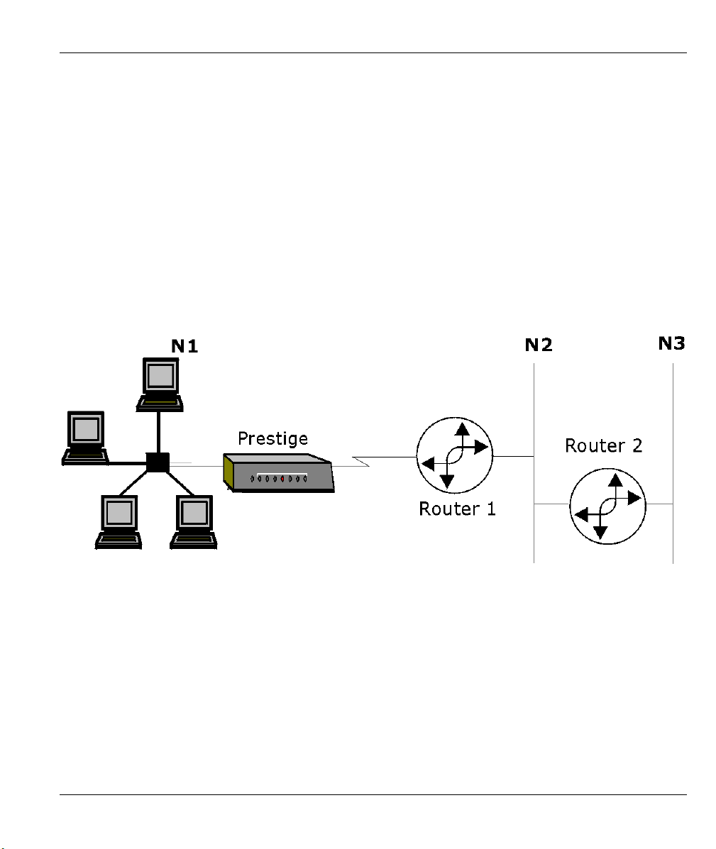
Prestige 310 Broadband Sharing Gateway
Chapter 5
IP Static Route Setup
This chapter shows you how to configure static routes with your Prestige.
Static routes tell the Prestige routing information that it cannot learn automatically through other means. This
can arise in cases where RIP is disabled on the LAN.
Each remote node specifies only the network to which the gateway is directly connected, and the Prestige has
no knowledge of the networks beyond. For instance, the Prestige knows about network N2 in the following
diagram through remote node router 1. However, the Prestige is unable to route a packet to network N3
because it doesn’t know that there is a route through the same remote node Router 1 (via gateway Router 2).
The static routes are for you to tell the Prestige about the networks beyond the remote nodes.
Figure 5-1 Example of Static Routing Topology
IP Static Route Setup 5-1

Prestige 310 Broadband Sharing Gateway
5.1 IP Static Route Setup
You configure IP static routes in menu 12. 1, by selecting one of the IP static routes as shown below. Enter
12 from the main menu.
Menu 12 - IP Static Route Setup
1. ________
2. ________
3. ________
4. ________
5. ________
6. ________
7. ________
8. ________
Enter selection number:
Figure 5-2 Menu 12 — IP Static Route Setup
Now, enter the index number of one of the static routes you want to configure.
Menu 12.1 - Edit IP Static Route
Route #: 1
Route Name= ?
Active= No
Destination IP Address= ?
IP Subnet Mask= ?
Gateway IP Address= ?
Metric= 2
Private= No
Press ENTER to CONFIRM or ESC to CANCEL:
Figure 5-3 Menu 12. 1 — Edit IP Static Route
The following table describes fields in Menu 12.1 — Edit IP Static Route Menu.
5-2 IP Static Route Setup

Prestige 310 Broadband Sharing Gateway
Table 5-1 IP Static Route Menu Fields
FIELD DESCRIPTION
Route # This is the index number of the static route that you chose in menu 12.
Route Name Enter a descriptive name for this route. This is for identification purposes only.
Active This field allows you to activate/deactivate this static route.
Destination IP
Address
IP Subnet Mask Enter the IP subnet mask for this destination.
Gateway IP
Address
Metric Metric represents the “cost” of transmission for routing purposes. IP routing uses hop
Private This parameter determines if the Prestige will include the route to this remote node in
Once you have completed filling in this menu, press [ENTER] at the message “Press ENTER to
Confirm…” to save your configuration, or press [ESC] to cancel.
This parameter specifies the IP network address of the final destination. Routing is
always based on network number. If you need to specify a route to a single host, use
a subnet mask of 255.255.255.255 in the subnet mask field to force the network
number to be identical to the host ID.
Enter the IP address of the gateway. The gateway is an immediate neighbor of your
Prestige that will forward the packet to the destination. On the LAN, the gateway must
be a router on the same segment as your Prestige; over the WAN, the gateway must
be the IP address of one of the Remote Nodes.
count as the measurement of cost, with a minimum of 1 for directly connected
networks. Enter a number that approximates the cost for this link. The number need
not be precise, but it must be between 1 and 15. In practice, 2 or 3 is usually a good
number.
its RIP broadcasts. If set to Yes, this route is kept private and not included in RIP
broadcast. If No, the route to this remote node will be propagated to other hosts
through RIP broadcasts.
IP Static Route Setup 5-3


Prestige 310 Broadband Sharing Gateway
Chapter 6
Network Address Translation (NAT)
This chapter discusses how to configure NAT on the Prestige.
6.1 Introduction
NAT (Network Address Translation - NAT, RFC 1631) is the translation of the IP address of a host in a
packet, for example, the source address of an outgoing packet, used within one network to a different IP
address known within another network.
6.1.1 NAT Definitions
Inside/outside denotes where a host is located relative to the Prestige, for example, the workstations of your
subscribers are the inside hosts, while the web servers on the Internet are the outside hosts.
Global/local denotes the IP address of a host in a packet as the packet traverses a router, for example, the
local address refers to the IP address of a host when the packet is in the local network, while the global
address refers to the IP address of the host when the same packet is travelling in the WAN side.
Note that inside/outside refers to the location of a host, while global/local refers to the IP address of a host
used in a packet. Thus, an inside local address (ILA) is the IP address of an inside host in a packet when the
packet is still in the local network, while an inside global address (IGA) is the IP address of the same inside
host when the packet is on the WAN side. The following table summarizes this information.
Table 6-1 NAT Definitions
TERM DESCRIPTION
Inside This refers to the host on the LAN.
Outside This refers to the host on the WAN.
Local This refers to the packet address (source or destination) as the packet travels on the LAN.
Global This refers to the packet address (source or destination) as the packet travels on the
WAN.
Network Address Translation (NAT) 6-1

Prestige 310 Broadband Sharing Gateway
NAT never changes the IP address (either local or global) of an outside host.
6.1.2 What NAT Does
In the simplest form, NAT changes the source IP address in a packet received from a subscriber (the inside
local address) to another (the inside global address) before forwarding the packet to the WAN side. When
the response comes back, NAT translates the destination address (the inside global address) back the inside
local address before forwarding it to the original inside host. Note that the IP address (either local or global)
of an outside host is never changed.
The global IP addresses for the inside hosts can be either static or dynamically assigned by the ISP. In
addition, you can designate servers, for example, a web server and a telnet server, on your local network and
make them accessible to the outside world. If you do not define any servers (for Many-to-One and Many-toMany Overload mapping – see Table 6-2), NAT offers the additional benefit of firewall protection. If no
server is defined in these cases, all incoming inquiries will be filtered out by your Prestige, thus preventing
intruders from probing your network. For more information on IP address translation, refer to RFC 1631, The
IP Network Address Translator (NAT).
6.1.3 How NAT Works
Each packet has two addresses – a source address and a destination address. For outgoing packets, the ILA
(Inside Local Address) is the source address on the LAN, and the IGA (Inside Global Address) is the source
address on the WAN. For incoming packets, the ILA is the destination address on the LAN, and the IGA is
the destination address on the WAN. NAT maps private (local) IP addresses to globally unique ones required
for communication with hosts on other networks. It replaces the original IP source address (and TCP or UDP
source port numbers for Many-to-One and Many-to-Many Overload NAT mapping) in each packet and then
forwards it to the Internet. The Prestige keeps track of the original addresses and port numbers so incoming
reply packets can have their original values restored. The following figure illustrates this.
6-2 Network Address Translation (NAT)

6.1.4 NAT Application
Prestige 310 Broadband Sharing Gateway
Figure 6-1 How NAT Works
The following figure illustrates a possible NAT application, where three inside LANs (logical LANs using IP
Alias) behind the Prestige can communicate with three distinct WAN networks. More examples follow at the
end of this chapter.
Network Address Translation (NAT) 6-3
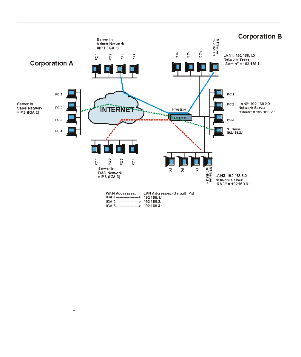
Prestige 310 Broadband Sharing Gateway
Figure 6-2 NAT Application With IP Alias
6.1.5 NAT Mapping Types
NAT supports five types of IP/port mapping. They are:
1. One to One: In One-to-One mode, the Prestige maps one local IP address to one global IP address.
2. Many to One: In Many-to-One mode, the Prestige maps multiple local IP addresses to one global IP
address. This is equivalent to SUA (i.e., PAT, port address translation), ZyXEL’s Single User Account
feature that previous ZyXEL routers supported (the SUA Only option in today’s routers).
3. Many to Many Overload: In Many-to-Many Overload mode, the Prestige maps the multiple local IP
addresses to shared global IP addresses.
4. Many One to One: In Many-One-to-One mode, the Prestige maps the each local IP addresses to unique
global IP addresses.
6-4 Network Address Translation (NAT)

Prestige 310 Broadband Sharing Gateway
5. Server: This type allows you to specify inside servers of different services behind the NAT to be
accessible to the outside world.
Port numbers do not change for One-to-One and Many-One-to-One NAT mapping
types.
The following table summarizes these types.
Table 6-2 NAT Mapping Types
TYPE IP MAPPING SMT ABBREVIATION
One-to-One ILA1ÅÆ IGA1 1:1
Many-to-One (SUA/PAT) ILA1ÅÆ IGA1
ILA2ÅÆ IGA1
…
Many-to-Many Overload ILA1ÅÆ IGA1
ILA2ÅÆ IGA2
ILA3ÅÆ IGA1
ILA4ÅÆ IGA2
…
Many-One-to-One ILA1ÅÆ IGA1
ILA2ÅÆ IGA2
ILA3ÅÆ IGA3
…
Server Server 1 IPÅÆ IGA1
Server 2 IPÅÆ IGA1
Server 3 IPÅÆ IGA1
M:1
M:M Ov
M:1:1
Server
6.2 Using NAT
6.2.1 SUA (Single User Account) Versus NAT
SUA (Single User Account) is a ZyNOS implementation of a subset of NAT that supports two types of
mapping, Many-to-One and Server. See section 6.3.1 for a detailed description of the NAT set for SUA.
Network Address Translation (NAT) 6-5

Prestige 310 Broadband Sharing Gateway
The Prestige also supports Full Feature NAT to map multiple global IP addresses to multiple private LAN
IP addresses of clients or servers using mapping types as outlined in Table 6-2.
1. Choose SUA Only if you have just one public WAN IP address for your Prestige.
2. Choose Full Feature if you have multiple public WAN IP addresses for your
Prestige.
6.2.2 Applying NAT
You apply NAT via menus 4 or 11.3 as displayed next. The next figure shows you how to apply NAT for
Internet access in menu 4. Enter 4 from the main menu to go to Menu 4 — Internet Access Setup.
Menu 4 - Internet Access Setup
ISP's Name= ChangeMe
Encapsulation= Ethernet
Service Type= Standard
My Login= N/A
My Password= N/A
Login Server IP= N/A
IP Address Assignment= Dynamic
IP Address= N/A
IP Subnet Mask= N/A
Gateway IP Address= N/A
Network Address Translation= SUA Only
Press ENTER to Confirm or ESC to Cancel:
Figure 6-3 Menu 4 — Applying NAT for Internet Access
The following figure shows how you apply NAT to the remote node in menu 11.1.
Step 1. Enter 11 from the main menu.
Step 2. Move the cursor to the Edit IP field, press [SPACE BAR] to select Yes and then press [ENTER]
to bring up Menu 11.3 — Remote Node Network Layer Options.
6-6 Network Address Translation (NAT)

Prestige 310 Broadband Sharing Gateway
Menu 11.3 - Remote Node Network Layer Options
IP Address Assignment= Dynamic
IP Address= N/A
IP Subnet Mask= N/A
Gateway IP Addr= N/A
Network Address Translation= SUA Only
Metric= N/A
Private= N/A
RIP Direction= None
Version= N/A
Multicast= None
Enter here to CONFIRM or ESC to CANCEL:
Press Space Bar to Toggle.
Figure 6-4 Menu 11.3 — Applying NAT to the Remote Node
The following table describes the options for Network Address Translation.
Table 6-3 Applying NAT in Menus 4 and 11.3
FIELD OPTIONS DESCRIPTION
Network
Address
Translation
Full
Feature
None
SUA Only
When you select this option the SMT will use Address Mapping Set 1
(menu 15.1 - see section 6.3.1 for further discussion). You can configure
any of the mapping types described in Table 6-2. Choose Full Feature if
you have multiple public WAN IP addresses for your Prestige.
NAT is disabled when you select this option.
When you select this option the SMT will use Address Mapping Set 255
(menu 15.1 - see section
6.3.1
). Choose SUA Only if you have just one
public WAN IP address for your Prestige.
6.3 NAT Setup
Use the Address Mapping Sets menus and submenus to create the mapping table used to assign global
addresses to computers on the LAN. You can see two NAT Address Mapping sets in menu 15.1. You can
only configure Set 1. Set 255 is used for SUA. When you select Full Feature in menu 4 or 11.3, the SMT
will use Set 1, which supports all mapping types as outlined in Table 6-2. When you select SUA Only, the
SMT will use the pre-configured Set 255 (read only).
Network Address Translation (NAT) 6-7

Prestige 310 Broadband Sharing Gateway
A server set is a list of LAN side servers mapped to external ports. To use this set (one set for the Prestige
50), a server rule must be set up inside the NAT Address Mapping set. Please see section 6.4 for further
information on these menus. To configure NAT, enter 15 from the main menu to bring up the following
screen.
Menu 15 — NAT Setup
1. Address Mapping Sets
2. Server Set
Enter Menu Selection Number:
Figure 6-5 Menu 15 — NAT Setup
6.3.1 Address Mapping Sets
Enter 1 to bring up Menu 15.1 — Address Mapping Sets.
Menu 15.1 — Address Mapping Sets
1. NAT_SET
255. SUA (read only)
Enter Menu Selection Number:
Figure 6-6 Menu 15.1 — Address Mapping Sets
SUA Address Mapping Set
Enter 255 to display the next screen. The fields in this menu cannot be changed.
6-8 Network Address Translation (NAT)

Prestige 310 Broadband Sharing Gateway
Menu 15.1.255 - Address Mapping Rules
Set Name= SUA
Idx Local Start IP Local End IP Global Start IP Global End IP Type
--- --------------- --------------- --------------- --------------- ------
1. 0.0.0.0 255.255.255.255 0.0.0.0 M-1
2. 0.0.0.0 Server
3.
4.
5.
6.
7.
8.
9.
10.
Press ENTER to Confirm or ESC to Cancel:
Figure 6-7 Menu 15.1.255 – SUA Address Mapping Rules
The fields in Menu 15.1.255 are read-only.
Table 6-4 SUA Address Mapping Rules
FIELD DESCRIPTION EXAMPLE
Set Name This is the name of the set you selected in menu 15.1 or
SUA
enter the name of a new set you want to create.
Idx This is the index or rule number. 1
Local Start IP
Local End IP
Local Start IP is the starting local IP address (ILA).
Local End IP is the ending local IP address (ILA). If the
0.0.0.0
255.255.255.255
rule is for all local IPs, then the Start IP is 0.0.0.0 and the
End IP is 255.255.255.255.
Global Start IP This is the starting global IP address (IGA). If you have a
0.0.0.0
dynamic IP, enter 0.0.0.0 as the Global Start IP.
Global End IP This is the ending global IP address (IGA). N/A
Type These are the mapping types discussed above (see
Table 6-2
). Server allows us to specify multiple servers
Server
of different types behind NAT to this machine. See later
for some examples.
Once you have finished configuring a rule in this menu, press [ENTER] at the message “Press ENTER to
Confirm…” to save your configuration, or press [ESC] to cancel.
Network Address Translation (NAT) 6-9

Prestige 310 Broadband Sharing Gateway
User-Defined Address Mapping Sets
Now let’s look at option 1 in menu 15.1. Enter 1 to bring up this menu. We’ll just look at the differences
from the previous menu. Note the extra Action and Select Rule fields mean you can configure rules in this
screen. Note also that the [?] in the Set Name field means that this is a required field and you must enter a
name for the set. If the Set Name field is left blank, the entire set will be deleted.
Menu 15.1.1 - Address Mapping Rules
Set Name= NAT_SET
Idx Local Start IP Local End IP Global Start IP Global End IP Type
--- --------------- --------------- --------------- --------------- ------
1.
2
3.
4.
5.
6.
7.
8.
9.
10.
Action= Edit Select Rule=N/A
Press ENTER to Confirm or ESC to Cancel:
Figure 6-8 Menu 15.1.1 — First Set
The Type, Local and Global Start/End IPs are configured in menu 15.1.1.1
(described later) and the values are displayed here.
Ordering Your Rules
Ordering your rules is important because the Prestige applies the rules in the order that you specify. When a
rule matches the current packet, the Prestige takes the corresponding action and the remaining rules are
ignored. If there are any empty rules before your new configured rule, your configured rule will be pushed up
by that number of empty rules. For example, if you have already configured rules 1 to 6 in your current set
and now you configure rule number 9. In the set summary screen, the new rule will be rule 7, not 9.
Now if you delete rule 4, rules 5 to 7 will be pushed up by 1 rule, so as old rule 5 becomes rule 4, old rule 6
becomes rule 5 and old rule 7 becomes rule 6.
6-10 Network Address Translation (NAT)

Prestige 310 Broadband Sharing Gateway
Table 6-5 Fields in Menu 15.1.1
FIELD DESCRIPTION EXAMPLE
Set Name Enter a name for this set of rules. This is a required field. If this
NAT_SET
field is left blank, the entire set will be deleted.
Action
The default is Edit. Edit means you want to edit a selected rule
Edit
(see following field). Insert Before means to insert a rule before
the rule selected. The rules after the selected rule will then be
moved down by one rule. Delete means to delete the selected rule
and then all the rules after the selected one will be advanced one
rule. None disables the Select Rule item.
Select Rule
When you choose Edit, Insert Before or Delete in the previous
1
field the cursor jumps to this field to allow you to select the rule to
apply the action in question.
You must press [ENTER] at the bottom of the screen to save the whole set. You
must do this again if you make any changes to the set – including deleting a rule.
No changes to the set take place until this action is taken.
—
Selecting Edit in the Action field and then selecting a rule brings up the following menu, Menu 15.1.1.1
Address Mapping Rule in which you can edit an individual rule and configure the Type, Local and Global
Start/End IPs.
An End IP address must be numerically greater than its corresponding IP Start
address.
Menu 15.1.1.1 Address Mapping Rule
Type= One-to-One
Local IP:
Start=
End = N/A
Global IP:
Start=
End = N/A
Press ENTER to Confirm or ESC to Cancel:
Press Space Bar to Toggle.
Figure 6-9 Menu 15.1.1.1 — Editing/Configuring an Individual Rule in a Set
Network Address Translation (NAT) 6-11

Prestige 310 Broadband Sharing Gateway
Table 6-6 Menu 15.1.1.1 — Editing/Configuring an Individual Rule in a Set
FIELD DESCRIPTION EXAMPLE
Type Press [SPACE BAR] to toggle through a total of five types. These
are the mapping types discussed in Table 6-2. Server allows you to
specify multiple servers of different types behind NAT to this
computer. See section 6.5.3 for an example.
Local IP
Global IP
Once you have finished configuring a rule in this menu, press [ENTER] at the message “Press ENTER to
Confirm…” to save your configuration, or press [ESC] to cancel.
Only local IP fields are N/A for server; Global IP fields MUST be set
for Server.
Start This is the starting local IP address (ILA). 0.0.0.0
End This is the ending local IP address (ILA). If the rule is for all local IPs,
then put the Start IP as 0.0.0.0 and the End IP as 255.255.255.255.
This field is N/A for One-to-One and Server types.
Start This is the starting global IP address (IGA). If you have a dynamic
IP, enter 0.0.0.0 as the Global IP Start. Note that Global IP Start
can be set to 0.0.0.0 only if the types are Many-to-One or Server.
This is the ending global IP address (IGA). This field is N/A for One-
End
to-One, Many-to-One and Server types.
One-to-One
N/A
0.0.0.0
N/A
6.4 NAT Server Sets – Port Forwarding
A NAT server set is a list of inside (behind NAT on the LAN) servers, for example, web or FTP, that you can
make visible to the outside world even though NAT makes your whole inside network appear as a single
machine to the outside world.
Use Menu 15 — NAT Setup to forward incoming service requests to the server(s) on your local network.
You may enter a single port number or a range of port numbers to be forwarded, and the local IP address of
the desired server. The port number identifies a service; for example, web service is on port 80 and FTP on
port 21. In some cases, such as for unknown services or where one server can support more than one service
(for example both FTP and web service), it might be better to specify a range of port numbers. Entry 12 (port
1026) is non-editable (see Figure 6-10).
In addition to the servers for specified services, NAT supports a default server. A service request that does
not have a server explicitly designated for it is forwarded to the default server. If the default is not defined,
the service request is simply discarded.
6-12 Network Address Translation (NAT)
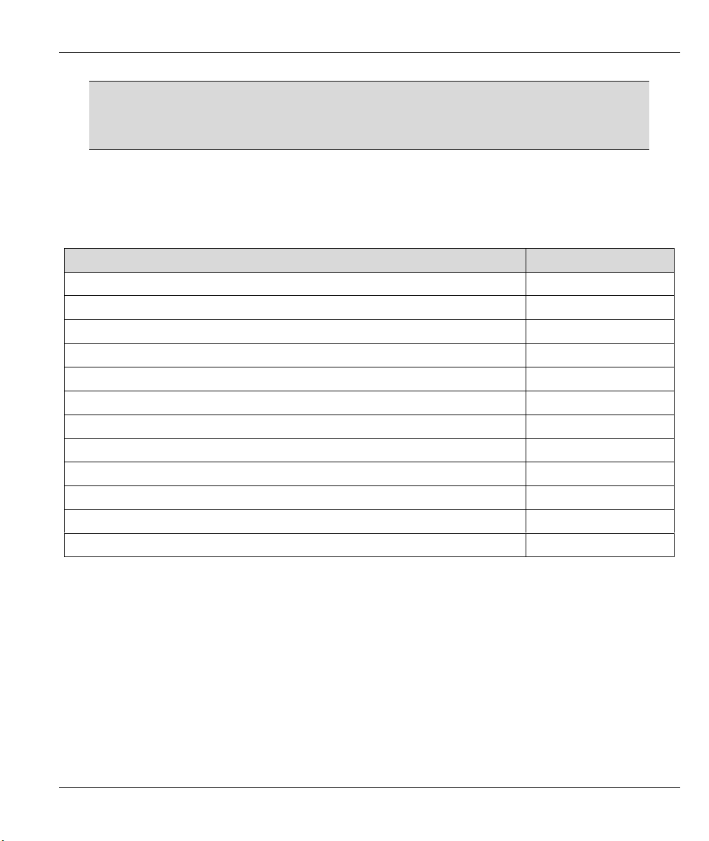
Prestige 310 Broadband Sharing Gateway
Many residential broadband ISP accounts do not allow you to run any server
processes (such as a Web or FTP server) from your location. Your ISP may
periodically check for servers and may suspend your account if it discovers any
active services at your location. If you are unsure, refer to your ISP.
The most often used port numbers are shown in the following table. Please refer to RFC 1700 for further
information about port numbers. Please also refer to the included disk for more examples and details on
NAT.
Table 6-7 Services & Port Numbers
SERVICES PORT NUMBER
ECHO 7
FTP (File Transfer Protocol) 21
Telnet 23
SMTP (Simple Mail Transfer Protocol) 25
DNS (Domain Name System) 53
Finger 79
HTTP (Hyper Text Transfer protocol or WWW, Web) 80
POP3 (Post Office Protocol) 110
NNTP (Network News Transport Protocol) 119
SNMP (Simple Network Management Protocol) 161
SNMP trap 162
PPTP (Point-to-Point Tunneling Protocol) 1723
6.4.1 Configuring a Server behind NAT
Follow these steps to configure a server behind NAT:
Step 1. Enter 15 in the main menu to go to Menu 15 — NAT Setup.
Step 2. Enter 2 to go to Menu 15.2 — NAT Server Setup.
Step 3. Enter a port number in an unused Start Port No field. To forward only one port, enter it again in
the End Port No field. To specify a range of ports, enter the last port to be forwarded in the End
Port No field.
Step 4. Enter the inside IP address of the server in the IP Address field. In the following figure, you have
a computer acting as an FTP, Telnet and SMTP server (ports 21, 23 and 25) at 192.168.1.33.
Network Address Translation (NAT) 6-13

Prestige 310 Broadband Sharing Gateway
Step 5. Press [ENTER] at the “Press ENTER to confirm …” prompt to save your configuration after you
define all the servers or press [ESC] at any time to cancel.
Menu 15.2 - NAT Server Setup
Rule Start Port No. End Port No. IP Address
---------------------------------------------------
1. Default Default 0.0.0.0
2. 21 25 192.168.1.33
3. 0 0 0.0.0.0
4. 0 0 0.0.0.0
5. 0 0 0.0.0.0
6. 0 0 0.0.0.0
7. 0 0 0.0.0.0
8. 0 0 0.0.0.0
9. 0 0 0.0.0.0
10. 0 0 0.0.0.0
11. 0 0 0.0.0.0
12. 1026 1026 RR Reserved
Press ENTER to Confirm or ESC to Cancel:
Figure 6-10 Menu 15.2 — NAT Server Setup
Figure 6-11 Multiple Servers Behind NAT Example
6-14 Network Address Translation (NAT)

Prestige 310 Broadband Sharing Gateway
6.5 General NAT Examples
6.5.1 Example 1: Internet Access Only
In the following Internet access example, you only need one rule where all your ILAs (Inside Local
addresses) map to one dynamic IGA (Inside Global Address) assigned by your ISP.
Figure 6-12 NAT Example 1
Menu 4 - Internet Access Setup
ISP's Name= ChangeMe
Encapsulation= Ethernet
Service Type= Standard
My Login= N/A
My Password= N/A
Login Server IP= N/A
IP Address Assignment= Dynamic
IP Address= N/A
IP Subnet Mask= N/A
Gateway IP Address= N/A
Network Address Translation= SUA Only
Press ENTER to Confirm or ESC to Cancel:
Figure 6-13 Menu 4 — Internet Access and NAT Example
Network Address Translation (NAT) 6-15
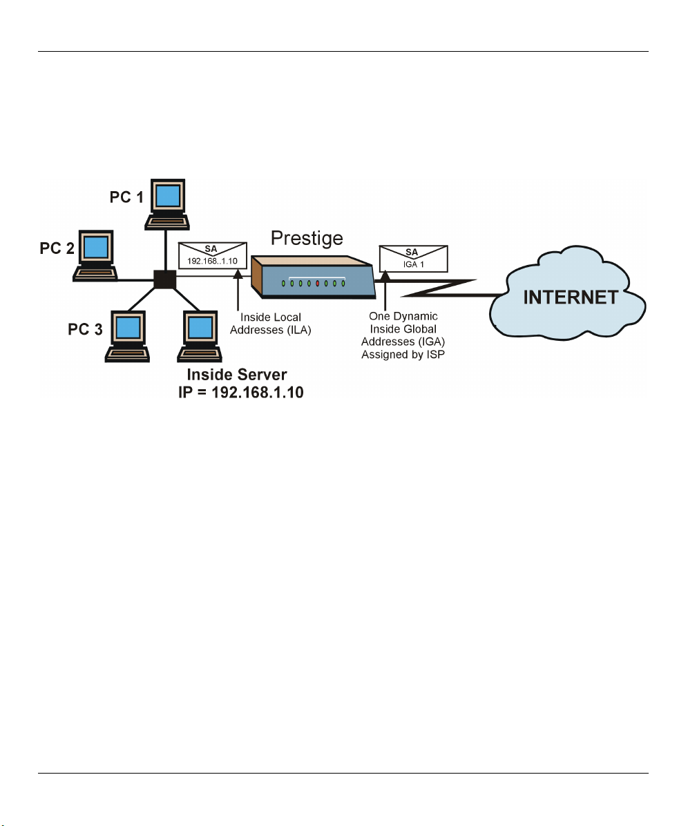
Prestige 310 Broadband Sharing Gateway
From menu 4 shown above, simply choose the SUA Only option from the Network Address Translation
field. This is the Many-to-One mapping discussed in section 6.5. The SUA Only read-only option from the
Network Address Translation field in menus 4 and 11.3 is specifically pre-configured to handle this case.
6.5.2 Example 2: Internet Access with an Inside Server
Figure 6-14 NAT Example 2
In this case, you do exactly as above (use the convenient pre-configured SUA Only set) and also go to menu
15.2 to specify the Inside Server behind the NAT as shown in the next figure.
6-16 Network Address Translation (NAT)

Prestige 310 Broadband Sharing Gateway
Menu 15.2 - NAT Server Setup
Rule Start Port No. End Port No. IP Address
---------------------------------------------------
1. Default Default 192.168.1.10
2. 0 0 0.0.0.0
3. 0 0 0.0.0.0
4. 0 0 0.0.0.0
5. 0 0 0.0.0.0
6. 0 0 0.0.0.0
7. 0 0 0.0.0.0
8. 0 0 0.0.0.0
9. 0 0 0.0.0.0
10. 0 0 0.0.0.0
11. 0 0 0.0.0.0
12. 1026 1026 RR Reserved
Press ENTER to Confirm or ESC to Cancel:
Figure 6-15 Menu 15.2 — Specifying an Inside Server
6.5.3 Example 3: Multiple Public IP Addresses With Inside Servers
In this example, there are 3 IGAs from our ISP. There are many departments but two have their own FTP
server. All departments share the same router. The example will reserve one IGA for each department with
an FTP server and all departments use the other IGA. Map the FTP servers to the first two IGAs and the
other LAN traffic to the remaining IGA. Map the third IGA to an inside web server and mail server. Four
rules need to be configured, two bi-directional and two uni-directional as follows.
Rule 1. Map the first IGA to the first inside FTP server for FTP traffic in both directions (1 : 1 mapping,
giving both local and global IP addresses).
Rule 2. Map the second IGA to our second inside FTP server for FTP traffic in both directions (1 : 1
mapping, giving both local and global IP addresses).
Rule 3. Map the other outgoing LAN traffic to IGA3 (Many : 1 mapping).
Rule 4. You also map your third IGA to the web server and mail server on the LAN. Type Server allows
you to specify multiple servers, of different types, to other computers behind NAT on the LAN.
The example situation looks somewhat like this:
Network Address Translation (NAT) 6-17
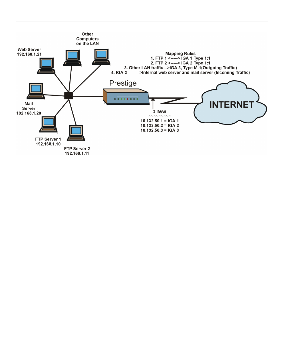
Prestige 310 Broadband Sharing Gateway
Figure 6-16 NAT Example 3
Step 1. In this case you need to configure Address Mapping Set 1 from Menu 15.1 — Address Mapping
Sets. Therefore you must choose the Full Feature option from the Network Address
Translation field (in menu 4 or menu 11.3) in Figure 6-17.
Step 2. Then enter 15 from the main menu.
Step 3. Enter 1 to configure the Address Mapping Sets.
Step 4. Enter 1 to begin configuring this new set. Enter a Set Name, choose the Edit Action and then
enter 1 for the Select Rule field. Press [ENTER] to confirm.
Step 5. Select Type as One-to-One (direct mapping for packets going both ways), and enter the local
Start IP as 192.168.1.10 (the IP address of FTP Server 1), the global Start IP as 10.132.50.1 (our
first IGA). (See Figure 6-18).
Step 6. Repeat the previous step for rules 2 to 4 as outlined above.
Step 7. When finished, menu 15.1.1 should look like as shown in Figure 6-19.
6-18 Network Address Translation (NAT)

Menu 11.3 - Remote Node Network Layer Options
IP Address Assignment= Dynamic
IP Address= N/A
IP Subnet Mask= N/A
Gateway IP Addr= N/A
Network Address Translation= Full Feature
Metric= N/A
Private= N/A
RIP Direction= None
Version= N/A
Enter here to CONFIRM or ESC to CANCEL:
Figure 6-17 Example 3: Menu 11.3
The following figure shows how to configure the first rule.
Menu 15.1.1.1 Address Mapping Rule
Type= One-to-One
Local IP:
Start= 192.168.1.10
End = N/A
Global IP:
Start= 10.132.50.1
End = N/A
Prestige 310 Broadband Sharing Gateway
Press ENTER to Confirm or ESC to Cancel:
Press Space Bar to Toggle.
Figure 6-18 Example 3: Menu 15.1.1.1
Network Address Translation (NAT) 6-19

Prestige 310 Broadband Sharing Gateway
Menu 15.1.1 - Address Mapping Rules
Set Name= Example3
Idx Local Start IP Local End IP Global Start IP Global End IP Type
--- --------------- --------------- --------------- --------------- ------
1. 192.168.1.10 10.132.50.1 1-1
2 192.168.1.11 10.132.50.2 1-1
3. 0.0.0.0 255.255.255.255 10.132.50.3 M-1
4. 10.132.50.3 Server
5.
6.
7.
8.
9.
10.
Action= Edit Select Rule=
Press ENTER to Confirm or ESC to Cancel:
Figure 6-19 Example 3: Final Menu 15.1.1
Now configure the IGA3 to map to our web server and mail server on the LAN.
Step 8. Enter 15 from the main menu.
Step 9. Now enter 2 from this menu and configure it as shown in Figure 6-20.
Menu 15.2 - NAT Server Setup
Rule Start Port No. End Port No. IP Address
---------------------------------------------------
1. Default Default 0.0.0.0
2. 80 80 192.168.1.21
3. 25 25 192.168.1.20
4. 0 0 0.0.0.0
5. 0 0 0.0.0.0
6. 0 0 0.0.0.0
7. 0 0 0.0.0.0
8. 0 0 0.0.0.0
9. 0 0 0.0.0.0
10. 0 0 0.0.0.0
11. 0 0 0.0.0.0
12. 1026 1026 RR Reserved
Press ENTER to Confirm or ESC to Cancel:
Figure 6-20 Example 3: Menu 15.2
6-20 Network Address Translation (NAT)

Prestige 310 Broadband Sharing Gateway
6.5.4 Example 4: NAT Unfriendly Application Programs
Some applications do not support NAT Mapping using TCP or UDP port address translation. In this case it is
better to use Many-One-to-One mapping as port numbers do not change for Many-One-to-One (and
One-to-One) NAT mapping types. The following figure illustrates this.
Figure 6-21 NAT Example 4
Other applications such as some gaming programs are NAT unfriendly because
they embed addressing information in the data stream. These applications won’t
work through NAT even when using One-to-One and Many-One-to-One mapping
types.
Follow the steps outlined in example 3 to configure these two menus as follows.
Network Address Translation (NAT) 6-21

Prestige 310 Broadband Sharing Gateway
Menu 15.1.1.1 Address Mapping Rule
Type= Many-One-to-One
Local IP:
Start= 192.168.1.10
End = 192.168.1.12
Global IP:
Start= 10.132.50.1
End = 10.132.50.3
Press ENTER to Confirm or ESC to Cancel:
Figure 6-22 Example 4: Menu 15.1.1.1 — Address Mapping Rule
After you’ve configured your rule, you should be able to check the settings in menu 15.1.1 as shown next.
Menu 15.1.1 - Address Mapping Rules
Set Name= Example4
Idx Local Start IP Local End IP Global Start IP Global End IP Type
--- --------------- --------------- --------------- --------------- ------
1. 192.168.1.10 192.168.1.12 10.132.50.1 10.132.50.3 M:1:1
2.
3.
4.
5.
6.
7.
8.
9.
10.
Action= Edit Select Rule=
Press ENTER to Confirm or ESC to Cancel:
Figure 6-23 Example 4: Menu 15.1.1 — Address Mapping Rules
6.6 Trigger Port Forwarding
The Prestige monitors outgoing data for a specific port number and protocol (trigger). When there is a match,
the Prestige records the IP address of the computer on the LAN that sent the matching data. When the
requested data comes back, the Prestige applies the port mapping rules and uses the recorded IP address to
get the data back to the proper computer.
6-22 Network Address Translation (NAT)

Prestige 310 Broadband Sharing Gateway
LAN computers dynamically take turns using the mapping based on the trigger port. There is no need to
reconfigure a new IP address each time you want a different computer (as you would with Port Forwarding)
to use the application.
6.6.1 Two Points To Remember About Trigger Ports
1. Trigger events only happen on data coming from inside the Prestige to the outside.
2. If an application needs a continuous data stream, that port (range) will be tied up so that another
computer on the LAN can’t trigger it.
Only one LAN computer can use a trigger port (range) at a time.
Enter 3 in menu 15 to display Menu 15.3 — Trigger Port Setup, shown next.
Menu 15.3 - Trigger Port Setup
Rule Name Start Port End Port Start Port End Port
----------------------------------------------------------------------
1. Real Audio 6970 7170 7070 7070
2. 0 0 0 0
3. 0 0 0 0
4. 0 0 0 0
5. 0 0 0 0
6. 0 0 0 0
7. 0 0 0 0
8. 0 0 0 0
9. 0 0 0 0
10. 0 0 0 0
11. 0 0 0 0
12. 0 0 0 0
Press ENTER to Confirm or ESC to Cancel:
Incoming Trigger
Figure 6-24 Menu 15.3—Trigger Port Setup
Table 6-8 Menu 15.3—Trigger Port Setup Description
FIELD DESCRIPTION EXAMPLE
Rule This is the rule index number. 1
Name Enter a unique name for identification purposes. You may enter up to 15
Real Audio
characters in this field. All characters are permitted - including spaces.
Incoming Incoming is a port (range) that accepts WAN traffic. It is the “listening “ port
of the client software on LAN computers.
Start Port Enter a port number or the starting port number in a range of port numbers. 6970
Network Address Translation (NAT) 6-23
 Loading...