


P-974H/HW Series
Cable Router
Default Login Details
IP Address http://
192.168.1.1:8080
User Name webadmin
Password 1234
Firmware Version 3.70
Edition 2, 09/2009
www.zyxel.com
www.zyxel.com
Copyright © 2009
ZyXEL Communications Corporation


About This User's Guide
About This User's Guide
Intended Audience
This manual is intended for people who want to configure the Zy XEL Device using
the web configurator. You should have at least a basic knowledge of TCP/IP
networking concepts and topology.
Related Documentation
•Quick Start Guide
The Quick Start Guide is designed to help you get up and running right away. It
contains information on setting up your network and configuring for Internet
access.
• Support Disc
Refer to the included CD for support documents.
• ZyXEL Web Site
Please refer to www.zyxel.com
product certifications.
for additional support documentation and
User Guide Feedback
Help us help you. Send all User Guide-related comments, questi ons or suggestions
for improvement to the following address, or use e-mail instead. Thank you!
The Technical Writing Team,
ZyXEL Communications Corp.,
6 Innovation Road II,
Science-Based Industrial Park,
Hsinchu, 300, Taiwan.
E-mail: techwriters@zyxel.com.tw
P-974H/HW Series User’s Guide
3

Document Conventions
Warnings and Notes
These are how warnings and notes are shown in this User’s Guide.
Warnings tell you about things that could harm you or your
device.
Note: Notes tell you other important information (for example, other things you may
need to configure or helpful tips) or recommendations.
Syntax Conventions
• This product may be referred to as the “ZyXEL Device”, the “device” or the
“system” in this User’s Guide.
Document Conventions
• Product labels, screen names, field labels and field choices are all in bold font.
• A key stroke is denoted by square brackets and uppercase text, for example,
[ENTER] means the “enter” or “ret urn” key on your keyboard.
• “Enter” means for you to type one or more characters and then press the
[ENTER] key. “Select” or “choose” means for you to use one of the predefined
choices.
• A right angle bracket ( > ) within a screen name denotes a mouse click. For
example, Maintenance > Log > Log Setting means you first click
Maintenance in the navigation panel, then the Log sub menu and finally the
Log Setting tab to get to that screen.
• Units of measurement may denote the “metric” value or the “scientific” value.
For example, “k” for kilo may denote “1000” or “1024”, “M” for mega may
denote “1000000” or “1048576” and so on.
• “e.g.,” is a shorthand for “for instance”, and “i.e.,” means “that is” or “in other
words”.
4
P-974H/HW Series User’s Guide
Document Conventions
Icons Used in Figures
Figures in this User’s Guide may use the following generic icons. The Z yXEL Device
icon is not an exact representation of your device.
ZyXEL Device Computer Notebook computer
Server Printer Firewall
Telephone Switch Router
P-974H/HW Series User’s Guide
5

Safety Warnings
• Use only No. 26 AWG (American Wire Gauge) or larger telecommunication line
cord.
• Do NOT use this product near water, for example, in a wet basement or near a
swimming pool.
• Do NOT expose your device to dampness, dust or corrosive liquids.
• Do NOT store things on the device.
• Do NOT install, use, or service this device during a thunderstorm. There is a
remote risk of electric shock from lightning.
• Connect ONLY suitable accessories to the device.
• Do NOT open the device or unit. Opening or removing cov ers can expose y ou to
dangerous high voltage points or other risks. ONLY qualified service personnel
should service or disassemble this device. Please contact your vendor for further
information.
Safety Warnings
• Make sure to connect the cables to the correct ports.
• Place connecting cables carefully so that no one will step on them or stumble
over them.
• Always disconnect all cables from this device before servicing or disassembling.
• Use ONLY an appropriate power adaptor or cord for your device.
• Connect the power adaptor or cord to the right supply voltage (for example,
110V AC in North America or 230V AC in Europe).
• Do NOT allow anything to rest on the power adaptor or cord and do NOT place
the product where anyone can walk on the power adaptor or cord.
• Do NOT use the device if the power adaptor or cord is damaged as it might
cause electrocution.
• If the power adaptor or cord is damaged, remove it from the power outlet.
• Do NOT attempt to repair the power adaptor or cord. Contact your local vendor
to order a new one.
• Do not use the device outside, and make sure all the connections are indoors.
There is a remote risk of electric shock from lightning.
• Do NOT obstruct the device ventilation slots, as insufficient airflow may harm
your device.
• Antenna Warning! This device meets FCC certification requiremen ts wh en u sin g
the included antenna(s). Only use the include d antenna(s).
6
• Make sure that the cable system is grounded so as to provide some protection
against voltage surges.
P-974H/HW Series User’s Guide
This product is recyclable. Dispose of it properly.
Safety Warnings
P-974H/HW Series User’s Guide
7

Safety Warnings
8
P-974H/HW Series User’s Guide

Table of Contents
Table of Contents
About This User's Guide..........................................................................................................3
Document Conventions............................................................................................................4
Safety Warnings ........................................................................................................................6
Table of Contents......................................................................................................................9
List of Figures.........................................................................................................................13
List of Tables...........................................................................................................................15
Part I: Introduction and Configuration................................................. 17
Chapter 1
Introduction.............................................................................................................................19
1.1 Overview ............. ............................................. ... .... ... ... ... .... ................................................ 19
1.2 Internet Access Application ................................................................................................. 19
1.3 Hardware Connection and Installation .................................... ................................ ............. 20
1.4 Front Panel LED Description ............................................................................................... 20
Chapter 2
The Web Configurator............................................................................................................23
2.1 Overview ............. ............................................. ... .... ... ... ... .... ................................................ 23
2.2 Accessing the Web Configurator ......................................................................................... 23
2.2.1 Logging Out of the Web Configurator ........................................................................ 24
2.2.2 Resetting the ZyXEL Device ...................................................................................... 24
2.3 Navigating the Web Configurator ............................................... .......................................... 25
2.4 Changing the Login Password ............................................................................................. 26
Chapter 3
Status.......................................................................................................................................29
3.1 Overview ............. ............................................. ... .... ... ... ... .... ................................................ 29
3.1.1 What You Can Do in This Chapter ............................................................................. 29
3.1.2 What You Need to Know .................................. ... ... .... ............................................. ... 29
3.2 Software .......................................... ... ... .... ............................................. ... ... .... ... ... ............. 31
3.3 Connection ......................................... ... .............................................. ... ... ... .... ... ... .............32
3.4 Event Log .............................................. .... ... ... ............................................. .... ... ... ............. 37
3.4.1 Event Log: Log Description ........................................................................................ 38
P-974H/HW Series User’s Guide
9

Table of Contents
Chapter 4
Basic ........................................................................................................................................43
4.1 Overview ............. ............................................. ... .... ... ... ... .... ................................................ 43
4.1.1 What You Can Do in This Chapter ............................................................................. 43
4.1.2 What You Need to Know .................................. ... ... .... ............................................. ... 43
4.2 DHCP ........................................ ... ... ... ... .... ............................................. ... ... .... ... ................44
Chapter 5
Advanced.................................................................................................................................45
5.1 Overview ............. ............................................. ... .... ... ... ... .... ................................................ 45
5.1.1 What Yo u Can Do in this Chapter .............................................................................. 45
5.1.2 What You Need to Know .................................. ... ... .... ............................................. ... 45
5.2 Options .. ... ... .... ... ... ... .... ............................................. ... ... .... ................................................ 46
5.3 IP Filtering ................................................. ... ... ... .... ... ... ... .................................................... 47
5.4 MAC Filtering ............................. ... ... ... ... .... .......................................................................... 48
5.5 Port Filtering .... ............................................. ... ... .... ... ... ... .................................................... 49
5.6 Port Forwarding .................................. ... .... .......................................................................... 50
Chapter 6
Wireless LAN...........................................................................................................................51
6.1 Overview ............. ............................................. ... .... ... ... ... .... ................................................ 51
6.1.1 What You Need to Know .................................. ... ... .... ............................................. ... 52
6.2 Basic WLAN Settings .......................................................................................................... 54
6.3 Wireless LAN Security ........................ ... .... ... ... ... .... ............................................................. 55
6.3.1 WEP Encryption ..... ... ... .... ... ... .................................................................................... 55
6.3.2 Introduction to WPA(2) .............................. .... ... ... ... .... ... ... ... ... .... ................................ 57
6.3.3 WPA/WPA2 ............................................ ... .... ... ... ... .... ... ... .......................................... 58
6.3.4 WPA-PSK/WPA2-PSK ................................................................................................60
6.4 Access Control .......................................... ... ... ............................................. .... ... ... ... .......... 61
Chapter 7
Maintenance............................................................................................................................63
7.1 Overview ............. ............................................. ... .... ... ... ... .... ................................................ 63
7.1.1 What Yo u Can Do in this Chapter .............................................................................. 63
7.2 Security ............ ............................................. ... ... .... ... ..........................................................63
7.3 Diagnostics .......................................................................... ... ... ... ... .... ... ... .......................... 64
7.4 Band ......... ............................................. .... ... ... ... .... ... .......................................................... 66
Part II: Appendices and Index............................................................... 69
Appendix A Product Specifications.........................................................................................71
10
P-974H/HW Series User’s Guide

Table of Contents
Appendix B Sample Configurations........................................................................................77
7.5 Overview ............. ............................................. ... .... ... ... ... .... ................................................ 77
7.6 Connecting to the ZyXEL Device with Telnet ....................................................................... 77
7.6.1 Set Static IP Only ... ... ... .............................................. ... ... ... ... ....................................78
7.6.2 Set Static IP with Public DHCP ..................................... ... ... ... .... ... ... ... ....................... 78
7.6.3 Set Static IP with NAT ............................................ .... ... ... ... ....................................... 79
7.6.4 Set Static IP with NAT and Private DHCP .................................................................. 79
7.6.5 Set Bridge Mode ................................................. ... .... ... ............................................. 80
7.6.6 Set Default IP Sharing / RG Mode ............................................................................. 80
Appendix C Setting up Your Computer’s IP Address.............................................................81
Appendix D Common Services ..............................................................................................99
Appendix E Legal Information..............................................................................................103
Appendix F Customer Support.............................................................................................107
Index.......................................................................................................................................113
P-974H/HW Series User’s Guide
11

Table of Contents
12
P-974H/HW Series User’s Guide

List of Figures
List of Figures
Figure 1 Internet Access Application .............................................. ... .... ... ... .......................................... 19
Figure 2 Front Panel LEDs: P-974H ....................................................................................................... 20
Figure 3 Front Panel LEDs: P-974HW ................................................................................................... 20
Figure 4 Status ...................................................................................................................................... 25
Figure 5 Maintenance: Security ............................................................................................................. 26
Figure 6 Status: SOFTWARE ................................................................................................................ 31
Figure 7 Status: CONNECTION ............................................................................................................ 32
Figure 8 Status: EVENT LOG ................................................................................................................ 37
Figure 9 Basic: DHCP ........................................................................................................................... 44
Figure 10 Advanced: Options ................................................................................................................ 46
Figure 11 Advanced: IP Filtering ........................................................................................................... 47
Figure 12 Advanced: MAC Filtering ....................................................................................................... 48
Figure 13 Advanced: Port Filtering ........................................................................................................ 49
Figure 14 Advanced: Forwarding .......................................................................................................... 50
Figure 15 Example of a Wireless Network .............................................................................................51
Figure 16 Wireless: Basic ...................................................................................................................... 54
Figure 17 Wireless: Security: WEP ....................................................................................................... 56
Figure 18 Wireless: Security: WPA .................................... ... .............................................. ... ... ............. 58
Figure 19 Wireless: Security: WPA-PSK ............................................................................................... 60
Figure 20 Wireless: Access Control ...................................................................................................... 61
Figure 21 Maintenance: Security ........................................................................................................... 63
Figure 22 Maintenance: Diagnostic (Ping) ........................................................................................... 64
Figure 23 Maintenance: Diagnostic (Traceroute) ................................................................................. 65
Figure 24 Maintenance: Band ............................................................................................................... 66
Figure 25 WIndows 95/98/Me: Network: Configuration ............................. ... .......................................... 82
Figure 26 Windows 95/98/Me: TCP/IP Properties: IP Address .............................................................. 83
Figure 27 Windows 95/98/Me: TCP/IP Properties: DNS Configuration ........ ... ... .... ... ............................. 84
Figure 28 Windows XP: Start Menu ........................................................................................................ 85
Figure 29 Windows XP: Control Panel .................. ... .... ... ... ... .... ... ... ... .... ... ... ... ... .................................... 85
Figure 30 Windows XP: Control Panel: Network Connections: Properties ............................................. 86
Figure 31 Windows XP: Local Area Connection Properties ................................................................... 86
Figure 32 Windows XP: Internet Protocol (TCP/IP) Properties .............................................................. 87
Figure 33 Windows XP: Advanced TCP/IP Properties . ... ... ... .... ... ... ... .... ... ............................................. 88
Figure 34 Windows XP: Internet Protocol (TCP/IP) Properties .............................................................. 89
Figure 35 Macintosh OS 8/9: Apple Menu .............................................................................................. 90
Figure 36 Macintosh OS 8/9: TCP/IP ..................................................................................................... 91
Figure 37 Macintosh OS X: Apple Menu ................................................................................................92
Figure 38 Macintosh OS X: Network ...................................................................................................... 92
P-974H/HW Series User’s Guide
13

List of Figures
Figure 39 Red Hat 9.0: KDE: Network Configuration: Devices ............................................................. 93
Figure 40 Red Hat 9.0: KDE: Ethernet Device: General ...................................................................... 94
Figure 41 Red Hat 9.0: KDE: Network Configuration: DNS ................................................................... 94
Figure 42 Red Hat 9.0: KDE: Network Configuration: Activate .................. ... ....................................... 95
Figure 43 Red Hat 9.0: Dynamic IP Address Setting in ifconfig-eth0 ................................................... 95
Figure 44 Red Hat 9.0: Static IP Address Setting in ifconfig-eth0 ................................ .... ... ... ... ... .... ... 96
Figure 45 Red Hat 9.0: DNS Settings in resolv.conf ............................................................................ 96
Figure 46 Red Hat 9.0: Restart Ethernet Card ..................................................................................... 96
Figure 47 Red Hat 9.0: Checking TCP/IP Properties ........................................................................... 97
14
P-974H/HW Series User’s Guide

List of Tables
List of Tables
Table 1 Front Panel LEDs ...................................................................................................................... 20
Table 2 Web Configurator Screens Summary ....................................................................................... 25
Table 3 Maintenance: Security .............................................................................................................. 27
Table 4 Status: SOFTWARE .................................................................................................................. 31
Table 5 Status: CONNECTION .............................................................................................................. 33
Table 6 Status: CONNECTION: Startup Procedure ............................................................................... 35
Table 7 Status: EVENT LOG ................................................................................................................. 37
Table 8 Event Log: Severity Levels ....................................................................................................... 37
Table 9 Event Log: Log Description ....................................................................................................... 38
Ta ble 10 Basic: DHCP ............. ... .... ... ... ... .... ... ... ... ... .... ................................................ ... .... ...................44
Table 11 Advanced: Options .................................................................................................................. 46
Table 12 Advanced: IP Filtering ............................................................................................................. 47
Table 13 Advanced: MAC Filtering ........................................................................................................ 48
Table 14 Advanced: Port Filtering .......................................................................................................... 49
Table 15 Advanced: Forwarding ............................................................................................................50
Table 16 Types of Encryption for Each Type of Authentication ............................................................. 53
Table 17 Wireless: Basic ....................................................................................................................... 54
Table 18 Wireless: Security: WEP Encryption .......................................................................................56
Table 19 Wireless: Security: WP A/WPA2 ..............................................................................................59
Table 20 Wireless: Security: WPA-PSK ................................................................................................. 60
Table 21 Wireless: Access Control ........................................................................................................ 62
Table 22 Maintenance: Security ............................................................................................................ 64
Table 23 Maintenance: Diagnostics (Ping) ............................................................................................ 65
Table 24 Maintenance: Diagnostics (Traceroute) .................................................................................. 66
Table 25 Maintenance: Band ................................................................................................................. 67
Table 26 Firmware Features .................................................................................................................. 71
Table 27 IEEE802.11b/g ........................................................................................................................ 72
Table 28 Device Specifications .............................................................................................................. 72
Table 29 P-974H /HW Pow er Adaptor Specifications ... ... ... ... .... ... ... ... .... ... ... ... ... .... ... ... ... .... ... ... ... ... .... ... 74
Table 30 Commonly Used Services ....................................................................................................... 99
P-974H/HW Series User’s Guide
15

List of Tables
16
P-974H/HW Series User’s Guide

PART I
Introduction and
Configuration
Introduction (19)
The Web Configurator (23)
Status (29)
Basic (43)
Advanced (45)
Wireless LAN (51)
Maintenance (63)
17

18
CHAPTER 1
Introduction
1.1 Overview
This user’s guide explains how to configure the following ZyXEL devices:
• The P-974H model is a 4-port cable modem and router combined. It also has a
USB 2.0 port allowing computers without an Ethernet connection to join your
network.
• The P-974HW model adds IEEE 802.11g wireless capability allowing wireless
clients to join your network.
This user’s guide refers to these models simply as the “ZyXEL Device”. Please
refer to Appendix A on page 71 for a complete list of features for your model.
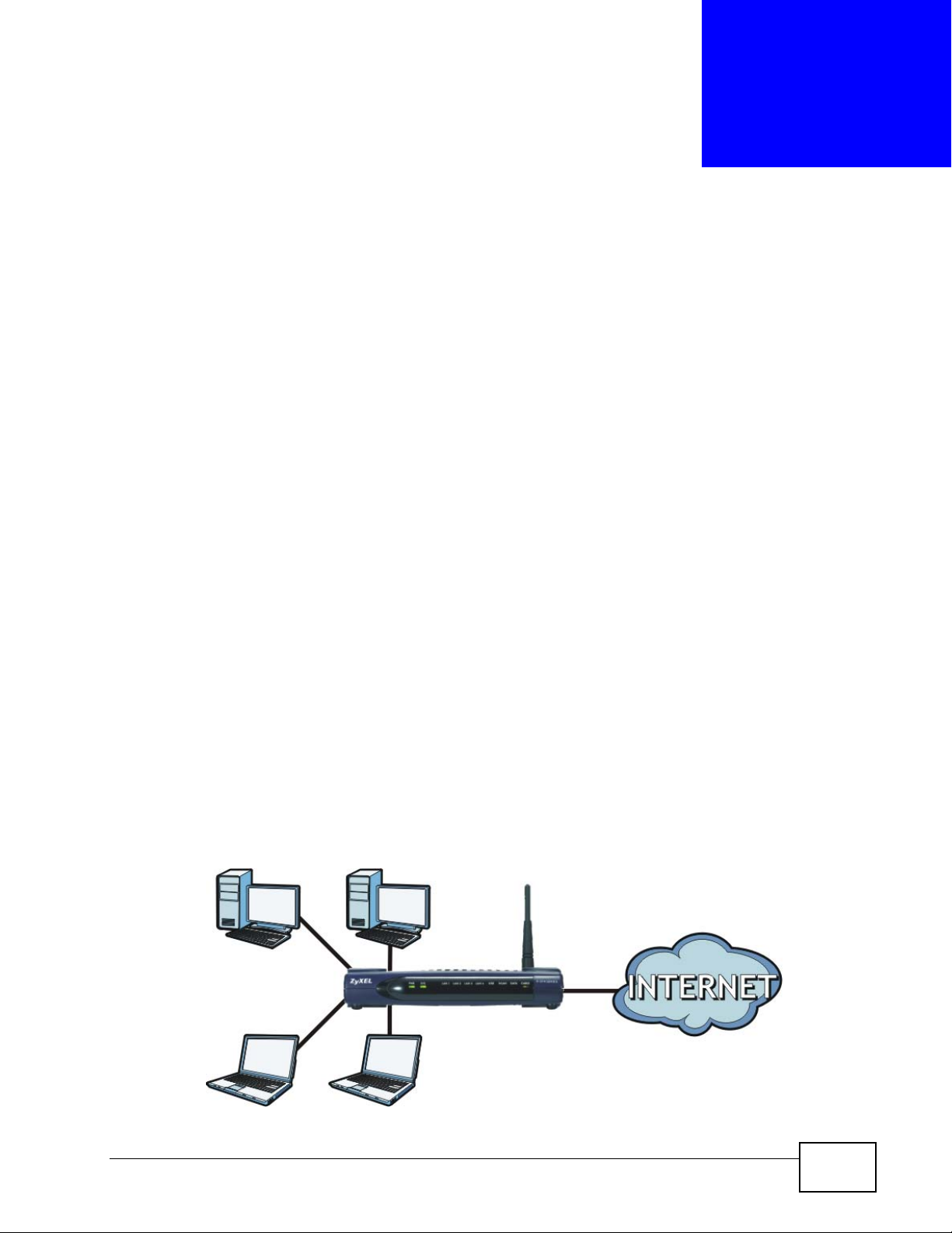
1.2 Internet Access Application
The ZyXEL Device is the ideal high-speed Internet access solution. It is compliant
with the DOCSIS 2.0 and Cable Home 1.1 standards. The ZyXEL Device allows you
to connect up to four computers to its 10/100 Mbps Ethernet ports and an
additional computer to its USB 2.0 port to form your local area network and
connect to the Internet. In addition, for P-974HW, wireless clients can access your
network resources and the Internet.
Figure 1 Internet Access Application
P-974H/HW Series User’s Guide
19
Chapter 1 Introduction
1.3 Hardware Connection and Installation
Refer to the Quick Start Guide for information for hardware connections and USB
driver installation.
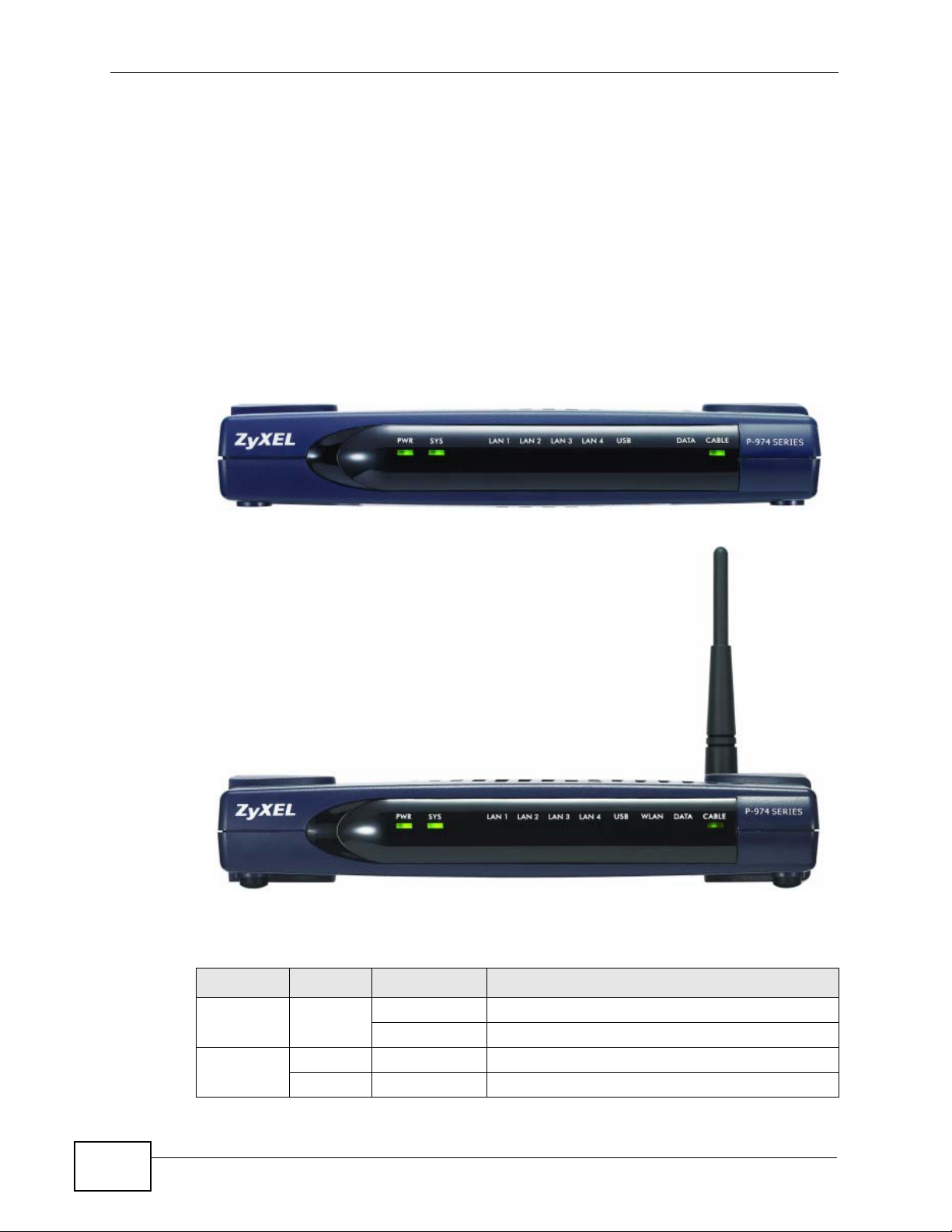
1.4 Front Panel LED Description
The following figures are front panel images of the P-974HW and P-974H models
respectively. The LED behavior is described at the end of this section.
Figure 2 Front Panel LEDs: P-974H
Figure 3 Front Panel LEDs: P-974HW
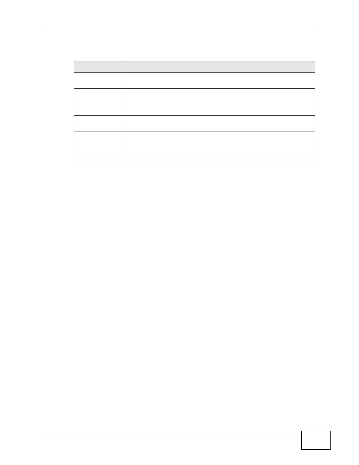
The following table describes the LEDs.
Table 1 Front Panel LEDs
LED COLOR STATUS DESCRIPTION
PWR Green On The ZyXEL Device is receiving power.
Off The ZyXEL Device is not receiving power.
SYS Green On The ZyXEL Device is functioning properly.
Off The system is not ready or has malfunctioned.
20
P-974H/HW Series User’s Guide

Chapter 1 Introduction
Table 1 Front Panel LEDs (continued)
LED COLOR STATUS DESCRIPTION
LAN 1...4 Green On The ZyXEL Device has a successful 10/100Mb
Ethernet connection.
Blinking The ZyXEL Device is sending/receiving data.
Off The LAN is not connected.
USB Green On A device is connected to the USB port on the
ZyXEL Device.
Blinking The ZyXEL Device is sending/receiving data via
the USB port.
Off The USB port is not connected.
WLAN Green On The wireless LAN is enabled.
Blinking The ZyXEL Device is sending/receiving data
through the wireless LAN.
Off The wireless LAN is disabled.
DATA Green Bl inking The ZyXEL Device is sending/receiving data on
the WAN.
Off The ZyXEL Device is not sending/receiving data
on the WAN.
CABLE Green On The ZyXEL Device has successfully registered to
the cable operator’s network.
Blinking The ZyXEL Device is trying to register with the
cable operator’s network.
Off The coaxial cable is not connected or the cable
link is down.
P-974H/HW Series User’s Guide
21

Chapter 1 Introduction
22
P-974H/HW Series User’s Guide
CHAPTER 2
The Web Configurator
2.1 Overview
The web configurator is an HTML-based management interface that allows easy
setup and management via an Internet browser. Use Internet Explorer 6.0 and
later or Firefox 1.5 and later versions. The recommended screen resolution is
1024 by 768 pixels.
In order to use the web configurator you need to allow:
• Web browser pop-up windows from your device. Web pop-up blocking is
enabled by default in Windows XP SP (S ervice Pack) 2.
• JavaScript (enabled by default).
• Java permissions (enabled by default).
See the chapter on troubleshooting to see how to make sure these functions are
allowed in Internet Explorer or Firefox.
2.2 Accessing the Web Configurator
Follow the steps below to log into the web configurator.
1 Launch your web browser. Enter “192.168.1.1:8080” as the web site address.
P-974H/HW Series User’s Guide
23
Chapter 2 The Web Configurator
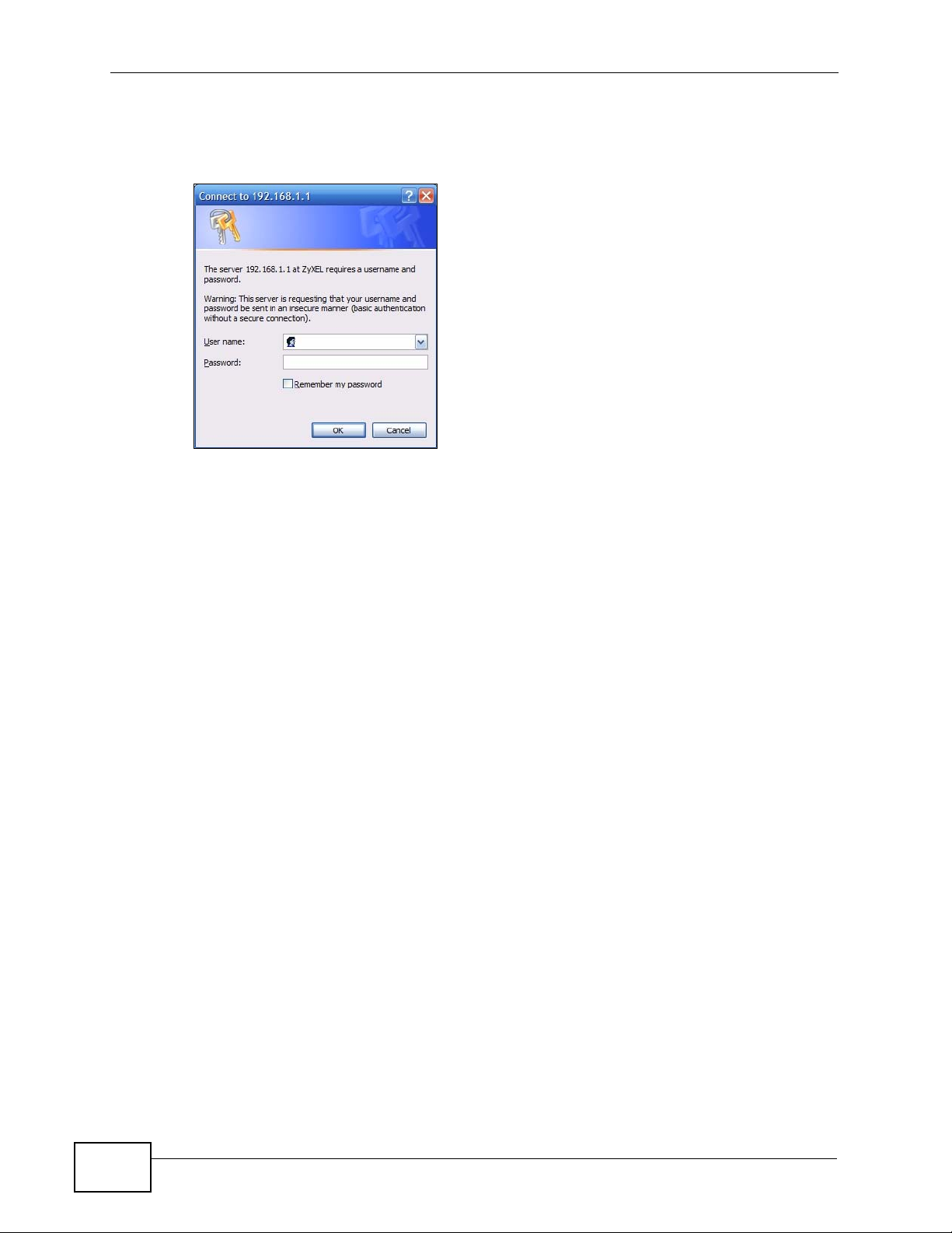
2 Enter the user name (“user” is the default) password (“1234” is the default) or
enter the administrator user name (“webadmin” is the default) and password
(“1234” is the default) and click OK.
3 You should now see the main Status screen (refer to Figure 4 on page 25).
2.2.1 Logging Out of the Web Configurator
To log out of the Web Configurator - perhaps to log in under a different account you must close the web browser in which it is displayed and then clear your
browser cache. If you do not, then the next time you re-open the web page in that
browser you may not have been properly logged out.
For instructions on how to empty your web browser cache, see the documentation
that shipped with it.
2.2.2 Resetting the ZyXEL Device
If you forget your password or cannot access the web configurator, you will need
to use the RESET button at the back of the ZyXEL Device to reload the factorydefault configuration file. This means that you will lose all configurations that you
had previously and the password will be reset to “1234”.
2.2.2.1 Using the RESET Button
1 Make sure the PWR and SYS LEDs are on (not blinking).
24
2 Press and hold the RESET button for about 15 seconds. All LEDs (except the
WLAN LED on the P-974HW) should turn on. When you release the RESET
button, the defaults have been restored and the ZyXEL Device restarts.
P-974H/HW Series User’s Guide
Chapter 2 The Web Configurator
You can also use the RESET button to restart the ZyXEL Device (without restoring
the defaults) by pressing down for 2 to 14 seconds.
2.3 Navigating the Web Configurator
The following summarizes how to navigate the web configurator from the main
Status screen.
Figure 4 Status
Following table lists the menu screens.
Table 2 Web Configurator Screens Summary
LINK SUB-LINK FUNCTION
Status Software Use this screen to view firmware and system related
Connection Use this screen to view LAN/WAN/WLAN connection
Event Log Use this screen to view system logs.
Basic DHCP Use this screen to configure DHCP settings on the LAN.
P-974H/HW Series User’s Guide
information.
information.
25
Chapter 2 The Web Configurator
Table 2 Web Configurator Screens Summary (continued)
LINK SUB-LINK FUNCTION
Advanced Options Use this screen to activate/deactivate WAN features
IP Filtering Use this screen to block access from one or a range of
MAC Filtering Use this screen to block access from the specified MAC
Port Filtering Use this screen to block access from one or a range of
Forwarding Use this screen to configure port forwarding on y our
Wireless
(P-974HW
Only)
Maintenance Security Use this screen to change system password or reset
Basic Use this screen to configure the wireless LAN settings.
Security Use this screen to configure WLAN authentication and
Access Control Use this screen to configure MAC filter settings on the
Bridging Use this screen to configure WLAN bridging.
Diagnostics These screens display information to help you identify
Band Use this screen to set up scan sets for Internet access
(such as IPSec passthrough and Multicast).
IP addresses.
address(es).
ports.
network.
security settings.
ZyXEL Device.
the ZyXEL Device back to the factory defaults.
problems with the ZyXEL Device general connection.
providers.
2.4 Changing the Login Password
It is highly recommended that you periodically change the password for accessing
the ZyXEL Device. If you didn’t change the default one after you logged in or you
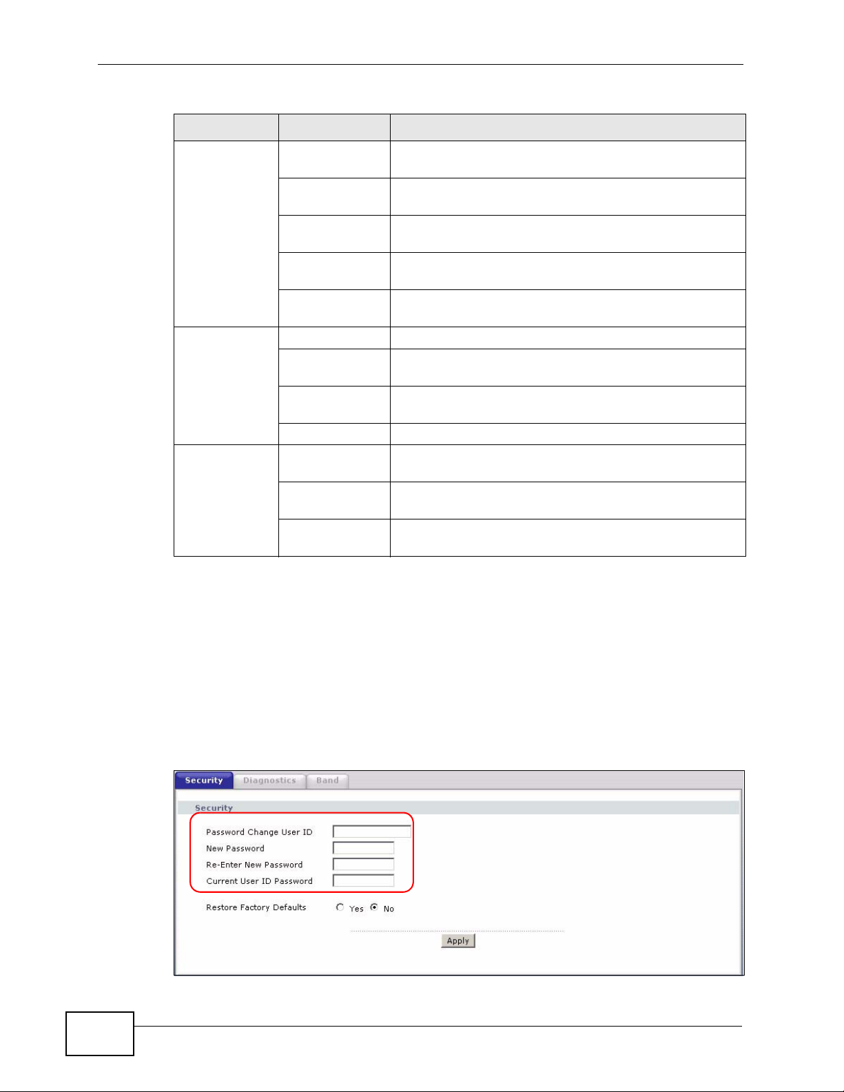
want to change to a new password again, then click Maintenance > Security to
display the screen as shown next.
Figure 5 Maintenance: Security
26
P-974H/HW Series User’s Guide
Chapter 2 The Web Configurator
The following table describes the related labels in this screen.
Table 3 Maintenance: Security
LABEL DESCRIPTION
Password
Change User ID
New Password Type the new password in this field.
Re-enter New
Password
Current User ID
Password
Apply Click Apply to save your changes.
Enter the login user name whose password you want to change. The
default user name is “user”.
Passwords may be up to 16 characters in length and must be
alphanumeric (a-z, A-Z, 0-9), no other characters are allowed.
Type the new password again in this field.
Type the default password or the existing password (associated with
the user name you enter above) you use to access the system in this
field. The default password is “1234”.
P-974H/HW Series User’s Guide
27

Chapter 2 The Web Configurator
28
P-974H/HW Series User’s Guide

CHAPTER 3
Status
3.1 Overview
This chapter describes the Status screens you can display to view firmware and
system information and system logs.
3.1.1 What You Can Do in This Chapter
•The Software screen screen allows you to view the overall status of y our device
(Section 3.2 on page 31).
•The Connection screen displays all of your network connection details (Section
3.3 on page 32).
•The Event Log screen provides a composite list of all system even records
(Section 3.4 on page 37).
3.1.2 What You Need to Know
The following terms and concepts may help as you read through this chapter.
Acquire Downstream Channel
In order to establish a successful connection with the cable provider’s network,
the ZyXEL Device must first find and lock onto a frequency for communication
with the cable operator’s network. The frequency is called a channel.
Communication with the cable operator’s network cannot proceed until the ZyXEL
Device finds the specific channel for sending and receiving data.
Connectivity State
The connectivity state is the current status of the connection between the cable
modem and your cable operator. During the initial negotiation with your cable
operator’s CMTS (Cable Modem Termination System), the ZyXEL Device must
establish a clear upstream and downstream channel, which it accomplishe s in a
series of well defined steps.
P-974H/HW Series User’s Guide
29

Chapter 3 Status
To provide Internet access services, a cable provider’s CMTS gets the incoming
traffic from the ZyXEL Device and routes the traffic to an ISP (Internet Service
Provider) to the Internet.
Boot State
When downloading the configuration file and booting, your ZyXEL Device passes
through several negotiation stages with the cable operator’s CMTS. All
communication steps: TFTP, DHCP Offer/Response, and Time Server must
complete in order for the configuration to be successful. TFTP is the download
protocol used to install the configuration file.
If there is a problem making a TFTP connection with the cable operator’s CMTS,
you will see the message Waiting for TFTP. If the ZyXEL Device does not receive
a DHCP offer from the cable operator’s CMTS you will see the message Waiting
for DHCP Offer. Once the Zy XEL Device has respon ded to the DHCP offer it again
waits for a response from the CMTS, if it does not receive a response you will see
the message Waiting for DHCP Response. If the cable operator’s time server
does not respond your will see the message Waiting for Timer Server. If the
download and installation of the configuration file succeeds you will see the
message Operational.
Your cable modem must receive an offer of a DHCP IP Address from the cable
operator’s CMTS and respond to that offer in order to set your IP Address. First
your cable modem is Waiting for DHCP Offer, if the offer is received by your
cable modem it responds Waiting for DHCP Response to the cable operator’s
CMTS. Once a response is received your IP Address is set and can be viewed
under the CM IP Address section of the Connection screen or in the Software
status screen. Note that the DHCP IP Address setting must be completed
successfully in order for your cable modem to download the configuration file.
Configuration File
This is the name of the cable modem configuration file downloaded from the cable
operator’s CMTS using the TFTP protocol. This is a binary format file which must
be DOCSIS 2.0 compliant (see RFC 2132 for additional information).
Security
Your cab le modem has features built -in to run Baseline Priv acy (BP). BP is used as
a privacy mechanism to protect user data flowing ac ross the cable net work and to
prevent unauthorized access to the cable operator’s CMTS data flowing across the
network. BP also supports access control lists (ACLs), filtering, tunnels, spoof
protection, and source IP filtering on the RF subnets to prevent users from using
IP addresses that are invalid. BP security information must be included in your
cable operator’s configuration file to enable security. If your cable operator did not
30
P-974H/HW Series User’s Guide

supply this information in the configuration file BP security is Disabled. Further
information can be found in DOCSIS 2.0.
Channels
Your ZyXEL Device uses different communications methods if it is receiving
information from the cable operator, or if it is sending information to the cable
operator. These are called the Downstream Channel and Upstream Channel
respectively. The channel numbers and frequencies are advertised by the cable
operator’s CMTS during t he initial booting of the Z yXEL Device; thes e may als o be
set in the configuration file.
3.2 Software
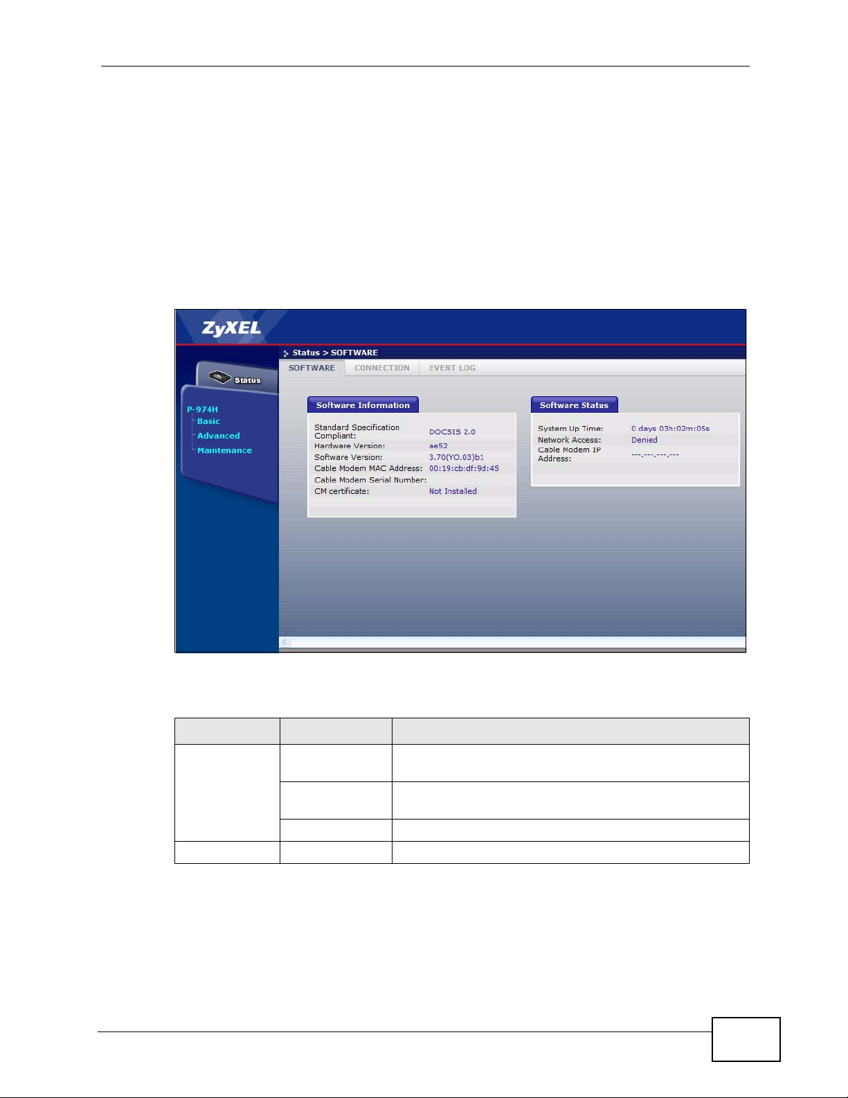
Click Status > SOFTWARE to display the following screen. These fields are readonly and strictly for diagnostic purposes.
Chapter 3 Status
Figure 6 S tatus: SOFTWARE
The following table describes the labels in this screen.
Table 4 Status: SOFTWARE
LABEL DESCRIPTION
Software
Information
Standard
Specification
Compliant
Hardware
Version
Software
Version
Cable Modem
MAC Address
Cable Modem
Serial Number
This field displays the name and version of the standard to which the
ZyXEL Device is compliant.
This field displays the hardware version number.
This is the firmware version.
This is the MAC (Media Access Control) or Ethernet address unique to
your ZyXEL De vice.
This is the serial number unique to your device.
P-974H/HW Series User’s Guide
31

Chapter 3 Status
Table 4 Status: SOFTWARE (continued)
LABEL DESCRIPTION
CM certificate Authentication certificates are required for the ZyXEL Device to
Software Status
System Up
Time
Network
Access
Cable Modem
IP Address
3.3 Connection
Click Status > CONNECTION to display the read-only screen.
establish a connection to the cable service provider’s network. This
field displays whether the authentication certificates are installed on
the ZyXEL Device.
This is the elapsed time the system has been up.
This field displays whether the ZyXEL Device is registered to the cable
service provider’s network.
This field displays the WAN IP address.
Figure 7 S tatus: CONNECTION
32
P-974H/HW Series User’s Guide

Chapter 3 Status
The following table describes the labels in this screen.
Table 5 Status: CONNECTION
LABEL DESCRIPTION
Startup
Procedure
Procedure This field displays the name of the initialization step.
Status This field displays the status of the initialization step.
Comment This field displays the status message of the initialization step.
Downstream/
Upstream
Channel
Lock Status The ZyXEL Device is either Locked or Not Locked on to the channel
Modulation This is the method used to encode transmission information, similar to
To establish a successful connection to the cable provider’s network,
the ZyXEL Device must go through a series of well-defined
initialization steps.
This table shows the line initialization information. For detailed
information for each initialization step, refer to Table 6 on page 35.
This is the data path used by the cable operator’s CMTS for sending/
receiving information to/from your ZyXEL Device.
advertised by the cable operator’s CMTS.
FM or AM on your radio.
The ZyXEL Device supports QAM64 (Quadrature Amplitude
Modulation) or QAM256 for the downstream channel.
The ZyXEL Device supports QAM16 or QPSK (Quadrature Phase Shift
Keying) for the upstream channel.
Channel ID A standard channel number from the DOCSIS 2.0 specification.
Channel numbers and channel frequencies are specified in pairs in
DOCSIS 2.0.
Symbol Rate The symbol rate (in Kilo symbols/second) for communication between
the cable operator’s CMTS and the ZyXEL Device. This is set during
initial configuration with a value supplied by the CMTS. Typical values
for QAM64 are 5.05 Mega-symbols/second, and for QAM256 5.36
Mega-symbols/second.
Downstream/
Upstream
Frequency
Downstream/
Upstream
Power
SNR This field is applicable for Downstream Channel.
Current System
Time
CM IP Address This is the IP address negotiated with your cable operator, after a
A standard channel frequency (in hertz) from the DOCSIS 2.0
specification.
The power level (in decibels/mili-volt). This value is set by the cable
operator’s CMTS.
The SNR (Signal to Noise Ratio), in decibels/mili-volt, is the ratio of
signal power to channel noise power. This value is set by the cable
operator’s CMTS.
successful download of the modem configuration file and DHCP
negotiation (e.g.10.21.0.11). This field may also be blanked out with a
series of dashed lines (--- --- --- ---) indicating that the modem
configuration failed or is in progress; no IP address has been set.
P-974H/HW Series User’s Guide
33

Chapter 3 Status
Table 5 Status: CONNECTION (continued)
LABEL DESCRIPTION
Duration The IP address negotiated with your cable operator has a default
lifetime of 7 days (e.g. D: 00 H: 01 M: 00 S: 00). The sequence (D --
H -- M -- S --) indicates that your modem configuration has failed or
is in progress; no IP address duration has been set.
Expires This is the expiration date of the IP address, after installation of the
modem configuration file and DHCP negotiation. The default is 7 days
(e.g. Wed Jul 02 00:26:23 2005). A sequence of dashes (--- --- -- -- -
- -- ----) indicates that your modem configuration has failed or is in
progress; no IP address expiry date has been set.
Current
System Time
This is the current date and time, and is set by your cable operator’s
time server.
34
P-974H/HW Series User’s Guide

3.3.0.1 Detailed Startup Procedure Information
The following table describes the status for each initialization step in the
CONNECTION screen.
Table 6 Status: CONNECTION: Startup Procedure
PROCEDURE STATUS COMMENT
Acquire
Downstream
Channel
Connectivity
State
The status message will display the
frequency in hertz (Hz) of the
channel the ZyXEL Device has locked
onto or is trying to lock onto.
This field displays:
• OK - The ZyXEL Device’s cable
connection is up and the upstream
and downstream channels are
established.
• In Progress - The ZyXEL Device
is trying to find and lock onto an
upstream channel.
This field displays:
• Locked - The ZyXEL Device has locked
onto the downstream channel.
• In Progress - The ZyXEL Device is
trying to find a downstream channel.
This field displays:
• Not Synchronized - The ZyXEL Device
can not synchronize the QAM signal
timing/FEC framing/MPEG packets or
obtain downstream channel MAC
address.
• Upstream Parameters Acquired - The
ZyXEL Device is trying to obtain the
upstream channel information from your
cable provider network.
• Ranging Complete - The Z yXEL Device
has successfully adjusted local channel
parameters (such as downstream power/
frequency and channel ID) within
specified ranges.
• IP Complete - The ZyXEL Device has
successfully obtained a WAN IP address
from a DHCP server.
• TOD Established - (Time Of Day) The
ZyXEL Device has obtained the system
time from a time server.
• Security Established - The baseline
privacy was requested in the
configuration file and initialized by the
ZyXEL Device.
• Params Transfer Complete - The
ZyXEL Device has received all
initialization parameters.
• Registration Complete - The ZyXEL
Device has successfully registered to the
cable provider network for Internet
access.
• Operational - The ZyXEL Device is has
successfully completed all the
initialization steps and is working fine.
• Access Denied - The ZyXEL Device was
unable to perform one or more of the
initialization steps.
Chapter 3 Status
P-974H/HW Series User’s Guide
35

Chapter 3 Status
Table 6 Status: CONNECTION: Startup Procedure (continued)
PROCEDURE STATUS COMMENT
Boot State This field displays:
This field displays:
• In Progress - The ZyXEL Device
is in the negotiation process with
the cable operator’s CMTS.
• OK - The ZyXEL Device completed
configuration.
Configuration
File
Security This field displays:
This field displays:
• OK - The ZyXEL Device obtains a
configuration file (cmb.cfg) from
the cable operator’s CMTS, and
installs it.
• In Progress - The ZyXEL Device
is trying to obtain a configuration
file from the cable operator’s
CMTS.
• Disabled - The ZyXEL Device’s WAN
connection has been disabled.
• Waiting for DHCP Offer - The ZyXEL
Device is waiting for a DHCP server to
offer it an IP address.
• Waiting for DHCP Response - The
ZyXEL Device is waiting for a response
from the DHCP server.
• Waiting for Time Server - The ZyXEL
Device is waiting for a response from the
time server.
• Waiting for TFTP - The ZyXEL Device is
waiting for a response from the TFTP
server.
• Operational - The ZyXEL Device has
successfully gone through the boot up
process.
• Refused by CMTS - The ZyXEL Device
could not complete one of the
initialization steps.
This field displays:
• The name of the configuration file on the
ZyXEL Device.
• Nothing if there was a problem in
obtaining or installing the configuration
file.
This field displays:
• Enabled - The baseline privacy
security is activated on the ZyXEL
Device.
• Disabled - The baseline privacy
security is disabled on the ZyXEL
Device.
• BPI+ - Baseline Privacy Interface is
activated.
• Disabled - Baseline Privacy is disabled.
36
P-974H/HW Series User’s Guide

3.4 Event Log
The Event Log screen displays system logs. The logs are useful for debugging
purposes when attempting to troubleshoot a connection problem between your
ZyXEL Device and the cable operator’s CMTS.
Click Status > EVENT LOG to display the screen as sh own.
Figure 8 S tatus: EVENT LOG
The following table describes the labels in this screen.
Chapter 3 Status
Table 7 Status: EVENT LOG
LABEL DESCRIPTION
Time This field displays the name of the log and the time created.
Priority This field displays the severity level of the log.
Description This field displays detailed information about the log.
Clear Log Click Clear Log to erase the log(s) in this screen.
The following table describes the log severity levels in the Priority field.
Table 8 Event Log: Severity Levels
ERROR LEVEL DESCRIPTION
Emergency 1 The event log requires immediate attention. Problems resulting
from this event may affect your Internet access connection.
Alert 2 A system or connection failure has occurred.
Critical 3 Action(s) should be taken to avoid a system or connection
failure.
Error 4 Action(s) should be taken to avoid possible future system or
connection failures.
Warning 5 Failure to solve this warning can lead to further system
problems,
Notice 6 Normal status. System administrators take notice.
Informational 7 Informational message only. May or may not be significant.
Debug 8 System debugging is turned on.
P-974H/HW Series User’s Guide
37

Chapter 3 Status
3.4.1 Event Log: Log Description
The following table describes the logs. Refer to DOCSIS 2.0 for additional
information on SNMP status messages for cable modems.
Table 9 Event Log: Log Description
LOG NAME SEVERITY DESCRIPTION
DHCP Warning Non-critical field
invalid in
response
DHCP ERROR The DHCP
response does
not contain all of
the required
fields or the PS
(Portal Services)
is unable to
determine
provisioning
mode.
SYNC Timing
Synchronization
failure - Failed to
acquire FEC
framing
SYNC Timing
Synchronization
failure - Failed to
acquire MAC
framing
SYNC Timing
Synchronization
failure, Acquired
FEC framing Failed to acquire
MPEG2 Sync
SYNC Timing
Synchronization
failure - Failed to
acquire QAM/
QPSK symbol
timing
SYNC Timing
Synchronization
failure - Failed to
receive MAC
SYNC frame
within time-out
period
Critical The ZyXEL Device has received a response to its DHCP request from
the cable operator’s CMTS, but the responding DHCP server did not
include all of the required fields in the message. This message might
also appear if one of the required fields in the DHCP message
contains an invalid value. Reconfigure the DHCP server so that it
sends all of the required fields.
Critical The ZyXEL Device has received a response to its DHCP request from
the cable operator’s CMTS, but the responding DHCP server did not
include all of the required fields in the message. Please refer to
appendix C of the DOCSIS 1.0 RF specification, appendix D of the
DOCSIS 1.1 RF specification, appendix D of the DOCSIS 2.0 RF
specification, and RFC 868 for further information. Reconfigure the
DHCP server so that it sends all of the required fields.
Critical When attempting to lock on to the downstream channel your ZyXEL
Device could not acquire forward error correction (FEC) framing.
Critical Your ZyXEL Device attempted to lock on to the downstream chann el
and was able to acquire forward error correction (FEC) framing, but
then failed to lock on to media access control (MAC) framing. Note
that this is not an ethernet MAC frametype.
Critical Your ZyXEL Device attempted to lock on to the downstream chann el
and was able to acquire forward error correction (FEC) framing, but
then failed to lock on to the MPEG2 synchronization signal.
Critical Your ZyXEL Device could not lock on to the downstream channel’s
quadrature amplitude modulation/quadrature phase shift keying
(QAM)/(QPSK) signal.
Critical Your ZyXEL Device was able to acquire the media access control
(MAC) framing initially, but subsequently failed to receive the MAC
SYNC frame within the specified timeout period. Note that this is not
an ethernet MAC frame type.
38
P-974H/HW Series User’s Guide

Table 9 Event Log: Log Description (continued)
LOG NAME SEVERITY DESCRIPTION
SW Upgrade
Failed Before
Download Server not
Present
SW upgrade
Failed after
download Incompatible
SW file
UCD invalid or
channel
unusable
A transmit
opportunity was
missed because
the MAP arrived
too late
DHCP FAILED Discover sent,
no offer received
DHCP FAILED Request sent,
No response
No UCD's
Received Timeout
Unicast Ranging
Received Abort
Response - Reinitializing MAC
SYNC Timing
Synchronization
failure - Loss of
Sync
No Maintenance
Broadcasts for
Ranging
opportunities
received - T2
time-out
Error Your ZyXEL Device has made 16 unsuccessful attempts to download
a new ZyXEL software image from the TFTP server (CMTS or other
TFTP server). After 16 attempts your cable modem aborts the
upgrade procedure. This error message might also occur if your
cable modem has received a fatal TFTP server error.
Error An upgrade of your ZyXEL Device software failed because the
downloaded image file was either the wrong image, type, or was
corrupted during file transfer.
Critical The cable modem received an Upstream Channel Descriptor (UCD)
message from the CMTS, but it contains invalid information or
specifies an upstream channel that is unusable.
Information Your ZyXEL Device missed a transmit opportunity because the
Bandwidth Allocation MAP (one slot of the Time Division
Multiplexing) signal arrived too late for your ZyXEL Device to use it.
Critical Your ZyXEL Device sent a DHCP discov ery broadcast message to the
cable operator’s CMTS, but no DHCP server or DHCP relay agent
replied with a DHCP offer response message.
Critical Your ZyXEL Device sent a DHCP discov ery broadcast message to the
cable operator’s CMTS, and received a DHCP offer message in
response from the cable operator, but when it sent a DHCP request
message to the indicated DHCP server, it did not receive a DHCP
response message.
Critical Your ZyXEL Device has not received any periodic Upstream Channel
Descriptor (UCD) messages from the CMTS within the specified
timeout period.
Critical Your ZyXEL Device is online and has sent a periodic R anging Request
(RNG-REQ) message to the CMTS, but it received an Abort Ranging
reply instead. Your ZyXEL Device will reset its cable interface and
restart the registration process in response. Note that this is not an
ethernet MAC frame type.
Critical Your ZyXEL Device had locked on to the downstream channel for a
period of time, but then the channel lock was lost and it was unable
to be reacquired within five SYNC signal periods. Your ZyXEL Device
has reset its cable interface in response to this condition.
Critical Your ZyXEL Device did not receive a broadcast maintenance
opportunity in which to transmit a Ranging Request (RNG-REQ)
within the required T2 timeout period (approximately 10 seconds).
Your ZyXEL Device will reset its cable interface and restart the
registration process.
Chapter 3 Status
P-974H/HW Series User’s Guide
39

Chapter 3 Status
Table 9 Event Log: Log Description (continued)
LOG NAME SEVERITY DESCRIPTION
Init RANGING
Critical Ranging
Request Retries
exhausted
Received
Response to
Broadcast
Maintenance
Request, But no
Unicast
Maintenance
opportunities
received - T4
timeout
No Ranging
Response
received - T3
time-out
Started Unicast
Maintenance
Ranging - No
Response
received - T3
time-out
TFTP Failed OUT OF ORDER
packets
TFTP file
complete - but
failed Message
Integrity check
MIC
TFTP failed request sent No Response
TFTP failed configuration file
NOT FOUND
Critical Your ZyXEL Device has sent 16 Ranging Request (RNG-REQ)
messages without receiving a Ranging Response (RNG-RSP) reply
message from your cable operator’s CMTS. Your ZyXEL Device will
reset its cable interface and restart the registration process. This
error message is typically caused by noise on the upstream channel
that causes the loss of MAC-layer messages. If your ZyXEL Device
cannot raise its upstream channel transmit power to a level that
allows successful communication within the maximum timeout
period, it resets its cable interface and restarts the registration
process.
Critical Your ZyXEL Device did not received a station maintenance
opportunity in which to transmit a Ranging Request (RNG-REQ)
message within the required T4 timeout period (30 to 35 seconds).
Your ZyXEL Device will reset its cable interface and restart the
registration process. Typically, this indicates an occasional,
temporary loss of service, but if the problem persists, check for
possible service outages or maintenance activity on the part of your
cable operator.
Critical Your ZyXEL Device sent a Ranging Request (RNG-REQ) message as
part of its initial ranging process, but did not receive a Ranging
Response (RNG-RSP) message from the CMTS within the required T3
timeout period. Your ZyXEL Device will adjust its upstream channel
transmit power and send another RNG-REQ message, up to the
maximum of 16 successive attempts, or until it reaches the
maximum transmit power level.
Critical Your ZyXEL Device is online and has sent a periodic Ranging R equest
(RNG-REQ) message to the CMTS, without receiving a Ranging
Response (RNG-RSP) message from the CMTS within the required T3
timeout period. Your ZyXEL Device will send another RNG-REQ
message, up to the maximum of 16 successive attempts.
Critical Your ZyXEL Device attempted to download its DOCSIS compliant
configuration file from the TFTP server, but the download failed
because the ZyXEL Device received at least one packet that was out
of order.
Critical Your ZyXEL Device successfully downloaded its configuration file, but
the Message Integrity Check (MIC) field sent with the configuration
file does not match the one that your ZyXEL Device generated
internally after checking the file’s contents. This could indicate either
that the configuration file was corrupted during file transfer, or that
the software tool that generated the configuration file was not
performing up to the DOCSIS standard. This message may also
indicate that a malicious user is attempting to download their own
configuration file as part of a theft-of-service attempt.
Critical Your ZyXEL Device attempted to download the configuration file
from the TFTP server specified by the DHCP server, but the TFTP
server has not replied.
Critical Your ZyXEL Device attempted to download its configuration file from
the TFTP server specified by the DHCP server, but the TFTP server
replied that it could not find the requested file.
40
P-974H/HW Series User’s Guide

Table 9 Event Log: Log Description (continued)
LOG NAME SEVERITY DESCRIPTION
ToD request
sent - No
Response
received
ToD Response
received Invalid data
format
UCC- REQ
received with
invalid or out of
range US
channel ID
UCC- REQ
received unable
to send UCCRSP, no TX
opportunity
US channel wide
parameters not
set before Burst
Descriptors
UCD & SYNC
valid - NO MAPS
for this channel
Warning Your ZyXEL Device sent a request to the time-of-day (ToD) server
specified by the DHCP server, but it did not receive a reply within the
specified timeout period. Your ZyXEL Device defaults to setting its
onboard clock to midnight on January 1, 1970. Your ZyXEL Device
can now proceed with the registration process without receiving a
ToD response, but will continue trying to contact the ToD server
every 5 minutes until it receives a valid response.
Warning Your ZyXEL Device received a reply from the ToD server that was
specified by the DHCP server. The reply from the ToD server was
either an empty datagram or it contained invalid data (the ToD
server should send a reply that contains only one 32-bit number that
indicates the number of seconds since midnight on January 1, 1900).
Please refer to RFC 868, Time Protocol for additional information.
The DOCSIS specifications do not allow the use of the Network Time
Protocol (NTP) or Simple Network Time Protocol (SNTP) ToD servers
to set your ZyXEL Device’s system time.
Error Your ZyXEL Device has received an Upstream Channel Change
Request (UCC-REQ) message from your cable operator’s CMTS that
contains an upstream channel ID that is either invalid or out of
range.
Error Your ZyXEL Device has received an Upstream Channel Change
Request (UCC-REQ) message from your cable operator’s CMTS, but
could not reply with an UCC Response message (UCC-RSP) because
it could not obtain a transmit timeslot.
Critical Your ZyXEL Device has received an Upstream Channel Descriptor
(UCD) message from the CMTS, but it did not set the channel and
symbol rate parameters before beginning the set of TLVs (Type
Length Value) that specify the burst descriptors for the upstream
channel. TLVs are an encoding for three fields: the first field is the
type of element, the second field is the length of the element, and
the third filed is the value of the element.
Critical Your ZyXEL Device has received valid Upstream Channel Descriptor
(UCD) and SYNC messages from the CMTS, but the upstream
channel that is specified in the UCD does not offer your ZyXEL
Device any MAP (one slot of the Time Division Multiplexing) minislots
in which to transmit.
Chapter 3 Status
P-974H/HW Series User’s Guide
41

Chapter 3 Status
42
P-974H/HW Series User’s Guide

CHAPTER 4
Basic
4.1 Overview
This chapter describes the screen you use to enable and configure your DHCP
server.
4.1.1 What You Can Do in This Chapter
The DHCP screen allows you to configure DHCP and IP address settings on the
LAN (Section 4.2 on page 44).
4.1.2 What You Need to Know
The following terms and concepts may help as you read through this chapter.
IP Address
A static IP is a fixed IP that you configure on the ZyXEL Device. A dynamic IP is
not fixed; a DHCP server provides an IP address to an Ethernet device each time it
connects to the network. When an Ethernet device is configured to obtain a
dynamic IP address from a DHCP server, it is known as a DHCP client.
DHCP
DHCP (Dynamic Host Configuration Protocol, RFC 2131 and RFC 2132) allows
individual clients to obtain TCP/IP configuration at start-up from a server. You can
configure the ZyXEL Device as a DHCP server or disable it on the LAN. When
configured as a server, the ZyXEL Device provides the TCP/IP configuration for the
DHCP clients. If DHCP service is disabled, you must have another DHCP server on
your LAN, or else the computers must be manually configured.
IP Pool Setup
You can config ure the start ing IP address that t he ZyXEL Device assigns to clients
as well as limit the number of devices which can obtain an IP address from the
ZyXEL Device.
P-974H/HW Series User’s Guide
43

Chapter 4 Basic
4.2 DHCP
Click Basic > DHCP to display the configuration screen. Use this screen to
configure DHCP and IP address settings on the LAN.
Figure 9 Basic: DHCP
The following table describes the labels in this screen.
Table 10 Basic: DHCP
LABEL DESCRIPTION
DHCP
DHCP Server Select Yes to set the Z yXEL Device as a DHCP server. Otherwise, select
No.
DHCP Server IP Enter the LAN IP address of the ZyXEL Device in the fields provided.
DHCP Server
Mask
Starting Local
Address
DHCP Pools Specify the number of IP addresses that the ZyXEL Device will give out
Lease Time Specify the time (in minutes between 1 and 71582788) a DHCP client is
Apply Click Apply to save the settings.
Enter the subnet mask associated with the LAN IP address.
Specify the first of the contiguous addresses in the IP address pool.
to DHCP clients.
allowed to use an assigned IP address. When the lease time expires,
the DHCP client is given a new, unused IP address.
44
P-974H/HW Series User’s Guide

CHAPTER 5
Advanced
5.1 Overview
This chapter describes the Advanced screen s you use to configure setti ngs such as
IP filtering, MAC filtering and port forwarding.
Use the Advanced screens to configure VPN passthrough, enable multicast,
filtering, and set up Network Address Translation (NAT) features.
5.1.1 What You Can Do in this Chapter
•The Options screen allows you to enable or disable advanced features such as
multicast and IPSec (Section 5.2 on page 46).
•The IP Filtering screen allows you to block access based on the IP address of a
computer on the LAN (Section 5.3 on page 47).
•The MAC Filtering screen allows y ou to block access based on the MAC address
of a computer on the LAN (Section 5.4 on page 48).
•The Port Filtering screen allows you to drop traffic based on service port
numbers and protocol types (Section 5.5 on page 49).
•The Port Forwarding screen allows you to forward tr affic to certain computers
on your network based on the port numbers of incoming traffic (Section 5.6 on
page 50).
5.1.2 What You Need to Know
The following terms and concepts may help as you read through this chapter.
VPN Pass Through Features
A Virtual Private Network (VPN) is a way to securely connect two networks over
the Internet. For example a home network and one in a business office. This
requires special equipment on both ends of the connection.
The ZyXEL Device is not one of the endpoints but it does allow traffic from those
endpoints to pass through. The ZyXEL Device allows the following types of VPN
traffic to pass through:
P-974H/HW Series User’s Guide
45

Chapter 5 Advanced
• IP security (IPSec)
• Point-to-Point Tunneling Protocol (PPTP)
5.2 Options
Use the Options screen to enable or disable advanced features (such as multicast
and IPSec).
Figure 10 Advanced: Options
The following table describes the labels in this screen.
Table 11 Advanced: Options
LABEL DESCRIPTION
Ipsec
PassThrough
PPTP
PassThrough
Multicast Enable Select this option to set the ZyXEL Device to forward multicast traffic.
Apply Click Apply to save the settings.
Select this option to allow the ZyXEL Device to pass through VPN traffic
using the IPsec protocol. Clear this option to disallow this type of VPN
traffic.
Select this option to allow the ZyXEL Device to pass through VPN traffic
using PPTP. Clear this option to disallow this type of VPN traffic.
The ZyXEL Device acts as an Internet Group Management Protocol
(IGMP) proxy and forwards multicast streams to multicast group
members on your network.
46
P-974H/HW Series User’s Guide

5.3 IP Filtering
You can set the ZyXEL Device to block access based on the IP address of a
computer on the LAN. Computers whose IP addresses are specified in the IP
Filtering screen are denied access to the ZyXEL Device and the Internet.
Click Advanced > IP Filtering to display the configuration screen.
Figure 11 Advanced: IP Filtering
Chapter 5 Advanced
The following table describes the labels in this screen.
Table 12 Advanced: IP Filtering
LABEL DESCRIPTION
Start Address Enter the IP address of a computer (or the beginning IP address of a
specific range of computers) on the LAN that you want the ZyXEL
Device to deny access.
End Address Type the ending IP address of a specific range of users on your LAN that
you want the ZyXEL Device to deny access. If you want to exclude only
one computer, enter the same IP address as in the Start Address field
above.
Enable Select Enable to block the computer(s) with the IP address(es) from
accessing the ZyXEL Device and/or the Internet.
Apply Click Apply to save the settings.
P-974H/HW Series User’s Guide
47

Chapter 5 Advanced
5.4 MAC Filtering
You can set the ZyXEL Device to block access based on the Media Access Control
(MAC) address of a computer on the LAN. Every Ethernet device has a unique MAC
address. The MAC address is assigned at the factory and consists of six pairs of
hexadecimal characters, for example “00:AC:12:00:01:15”.
Computers whose MAC addresses are specified in the MAC Filtering screen are
denied access to the ZyXEL Device and the Internet.
Click Advanced > MAC Filtering to display the configuration screen.
Figure 12 Advanced: MAC Filtering
The following table describes the labels in this screen.
Table 13 Advanced: MAC Filtering
LABEL DESCRIPTION
MAC Address Enter the MAC address of a computer you want the ZyXEL Device to
deny access.
Apply Click Apply to save the changes.
48
P-974H/HW Series User’s Guide

5.5 Port Filtering
You can set the ZyXEL Device to drop traffic based on service port numbers and
protocol types. This feature allows you to specify the applications (such as MSN
and TFTP) the computers on the LAN cannot use. See Appendix D on page 99 for
common services.
Click Advanced > Port Filtering to display the configuration screen.
Figure 13 Advanced: Port Filtering
Chapter 5 Advanced
The following table describes the labels in this screen.
Table 14 Advanced: Port Filtering
LABEL DESCRIPTION
Start Port Enter the beginning service port number whose traffic you want the
ZyXEL Device to block.
End Port Type the ending service port number whose traffic you want the ZyXEL
Device to block. If you want to exclude only one service, enter the same
service port number as in the Start Port field above.
Protocol Specify the traffic protocol type. Choices are TCP, UDP and Both.
Enabled Select Enabled to block traffic based on the selected port number(s)
and protocol type.
Apply Click Apply to save the settings.
P-974H/HW Series User’s Guide
49

Chapter 5 Advanced
5.6 Port Forwarding
You can set the ZyXEL Device to forward traffic to certain computers on your
network based on the port numbers of incoming traffic. For example, if you set up
an FTP server on your local network and you want it be available f rom the outside
your LAN. You can set up a forwarding rule that will send all FTP traffic coming
from the WAN to the FTP server on your network. Refer to Appendix D on page 99
for common port numbers and their associated services.
Click Advanced > Forwarding to display the configuration screen.
Figure 14 Advanced: Forwarding
The following table describes the labels in this screen.
Table 15 Advanced: Forwarding
LABEL DESCRIPTION
Local IP
Address
Start Port Type the starting service port number whose traffic y ou want the Z yXEL
End Port Type the ending service port number whose traffic you want the ZyXEL
Protocol Specify the traffic protocol type. Choices are TCP, UDP and Both.
Enabled Select Enabled to forward traffic based on the selected port number(s)
Apply Click Apply to save the settings.
Enter the IP address of a server or computer to which you want to
forward traffic incoming on the ports you specify.
Device to forward to the IP address you specified in the Local IP
Address field.
Device to forward to the IP address you specified in the Local IP
Address field. If you want to forward only one service, enter the same
service port number as in the Start Port field above.
and protocol type.
50
P-974H/HW Series User’s Guide

CHAPTER 6
Wireless LAN
6.1 Overview
This chapter discusses how to configure the wireless network settings in your
ZyXEL Device.
Note: This chapter is only applicable to the P-974HW model.
The following figure provides an example of a wireless network.
Figure 15 Example of a Wireless Network
The wireless network is the part in the blue circle. In this wireless network,
devices A and B use the access point (AP) to interact with the other devices (such
as the printer) or with the Internet. Your ZyXEL Device is the AP.
Every wireless network must follow these basic guidelines.
P-974H/HW Series User’s Guide
51

Chapter 6 Wireless LAN
• Every device in the same wireless network must use the same SSID.
The SSID is the name of the wireless network. It stands for Service Set
IDentity.
• If two wireless networks overlap, they should use a different channel.
Like radio stations or television channels, each wireless network uses a specific
channel, or frequency, to send and receive information.
• Every device in the same wireless network must use security compatible with
the AP.
Security stops unauthorized devices from using the wireless net work. It can also
protect the information that is sent in the wireless network.
6.1.1 What You Need to Know
The following terms and concepts may help as you read through this chapter.
SSID
Normally, the ZyXEL Device acts like a beacon and regularly broadcasts the SSID
in the area. You can hide the SSID instead, in which case the ZyXEL Device does
not broadcast the SSID. In addition, you should change the default SSID to
something that is difficult to guess.
This type of security is fairly weak, however, because there are ways for
unauthorized wireless devices to get the SSID. In addition, unauthorized wireless
devices can still see the in formation that is sent in the wireless network.
MAC Address Filter
Every device that can use a wireless network has a unique identification number,
called a MAC address.
characters
address for each device in the wireless network, see the device’s User’s Guide or
other documentation.
You can use the Access Control screen to tell the ZyXEL Device which devices
are allowed or not allowed to use the wireless network. If a device is allowed to
use the wireless network, it still has to have the correct information (SSID,
channel, and security). If a device is not allowed to use the wireless network, it
does not matter if it has the correct information.
2
; for example, 00A0C5000002 or 00:A0:C5:00:00:02. To get the MAC
1
A MAC address is usually written using twelve hexadecimal
52
This type of security does not protect the inf o rm at ion that is sent in the wireless
network. Furthermore, there are ways f or unauthorized wireless devices to get the
1. Some wireless devices, such as scanners, can detect wireless networks but cannot use wireless networks.
These kinds of wireless devices might not have MAC addresses.
2. Hexadecimal characters are 0, 1, 2, 3, 4, 5, 6, 7, 8, 9, A, B, C, D, E, and F.
P-974H/HW Series User’s Guide

Chapter 6 Wireless LAN
MAC address of an authorized device. Then, they can use that MAC address to use
the wireless network.
User Authentication
You can make every user log in to the wireless network before they can use it.
This is called user authentication. However, every device in the wireless network
has to support IEEE 802.1x to do this.
You need to configure a RADIUS server to set up user names and passwords for
your users.
Unauthorized wireless devices can still see the information that is sent in the
wireless network, even if they cannot use the wireless network. Furthermore,
there are ways for unauthorized wireless users to get a valid user name and
password. Then, they can use that user name and password to use the wireless
network.
Encryption
Wireless networks can use encryption to protect the informat ion that is sent in the
wireless network. Encryption is like a secret code. If you do not know the secret
code, you cannot understand the message.
The types of encryption you can choose depend on the type of authentication.
(See Section on page 53 for information about this.)
Table 16 Types of Encryption for Each Type of Authentication
NO AUTHENTICATION RADIUS SERVER
Weakest None IEEE 802.1x
Static WEP IEEE 802.1x + Static
WEP
WPA-PSK WPA
Strongest WPA2-PSK WPA2
For example, if the wireless network has a RADIUS server, you can choose IEEE
802.1x, IEEE 802.1x + WEP, WPA or WPA2. If users do not log in to the
wireless network, you can choose WEP, WPA-PSK, or WPA2-PSK.
Usually, you should set up the strongest encryp tion that every device in the
wireless network supports. For example, suppose you have a wireless network
with the ZyXEL Device. The ZyXEL Device does not have a local user database,
and you do not have a RADIUS server. Therefore, there is no authentication.
Suppose the wireless network has two devices. Device A only supports WEP, and
device B supports WEP and WPA. Therefore, you should set up WEP in the
wireless network.
P-974H/HW Series User’s Guide
53

Chapter 6 Wireless LAN
Note: It is recommended that wireless networks use WPA-PSK, WPA, or stronger
encryption. IEEE 802.1x and WEP encryption are better than none at all, but it
is still possible for unauthorized wireless devices to figure out the original
information pretty quickly.
Many types of encryption use a key to protect the information in the wireless
network. The longer the key, the stronger the encryption. Every device in the
wireless network must have the same key.
6.2 Basic WLAN Settings
To configure general WLAN settings, click WLAN > Basic to display the
configuration screen.
Figure 16 Wireless: Basic
The following table describes the labels in this screen.
Table 17 Wireless: Basic
LABEL DESCRIPTION
802.1b/g Basic
Wireless MAC
Address
Network Name
(SSID)
Network Type Select Open to make the SSID visible so a station can obtain the SSID
Country Select your country location in this field. The number of channels
This read-only field displays the MAC address of the built-in WLAN card.
The SSID (Service Set IDentification) is a unique name to identify the
ZyXEL Device in the wireless LAN. Wireless stations associating to the
ZyXEL Device must have the same SSID.
Enter a descriptive name of up to 32 printable characters (including
spaces; alphabetic characters are case-sensitive).
through AP scanning.
Select Closed to hide the SSID so a station cannot obtain the SSID
through AP scanning.
available in the Channel field vary depending on the country location
you select in this field.
54
P-974H/HW Series User’s Guide

Table 17 Wireless: Basic (continued)
LABEL DESCRIPTION
Channel The radio frequency used by wireless devices is called a channel.
Select a channel from the drop-down list box. The number of channels
available vary depending on what you select in the Country field.
Interface You should configure wireless security when you enable the wireless
LAN. Select Enable to activate the wireless LAN, otherwise select
Disable to deacitvate the wireless LAN.
Apply Click Apply to save the settings.
6.3 Wireless LAN Security
Wireless security is vital to your network to protect wireless communication
between wireless stations, access points and the wired network.
Wireless security methods available on the ZyXEL Device are data encryption,
wireless client authentication, restricting access by device MAC address and hiding
the ZyXEL Device identity.
Chapter 6 Wireless LAN
6.3.1 WEP Encryption
WEP encryption scrambles the data transmitted bet ween the wireless stations and
the access points to keep network communications private. It encrypts unicast
and multicast communications in a network. Both the wireless stations and the
access points must use the same WEP key.
Your ZyXEL Device allows you to configure up to four 64-bit or 128-bit WEP keys
but only one key can be enabled at any one time.
P-974H/HW Series User’s Guide
55

Chapter 6 Wireless LAN
Click Wireless > Security and select Disable in the WPA, WPA-PSK, WPA2
and WPA2-PSK fields to display the configuration screen.
Figure 17 Wireless: Security: WEP
56
The following table describes the WEP encryption related labels in this screen.
Table 18 Wireless: Security: WEP Encryption
LABEL DESCRIPTION
RADIUS Server Enter the IP address of the external authentication server in dotted
decimal notation. You only need to configure RADIUS server settings if
you enable 802.1x authentication.
RADIUS Port The default port of the RADIUS server for authentication is 1812.
You need not change this value unless your network administrator
instructs you to do so with additional information.
You only need to configure RADIUS server settings if you enable 802.1x
authentication.
RADIUS Key Enter a password (up to 31 alphanumeric characters) as the key to be
shared between the external authentication server and the access points.
The key is not sent over the network. This key must be the same on the
external authentication server and ZyXEL Device.
You only need to configure RADIUS server settings if you enable 802.1x
authentication.
P-974H/HW Series User’s Guide

Table 18 Wireless: Security: WEP Encryption (continued)
LABEL DESCRIPTION
WEP
Encryption
Shared Key
Authentication
WEP (Wired Equivalent Privacy) encrypts data frames before tr ansmitting
over the wireless network.
Select Disable to allow all wireless stations to communicate with the
access points without any data encryption.
Select WEP (64-bit) or WEP (128-bit) to use data encryption.
Select Required to use the selected WEP key for basic wireless
authentication.
Select Disabled to set the ZyXEL Device not to perform basic wireless
authentication with a WEP key.
Note: You can only configure 802.1x Authentication settings if
Shared Key Authentication is set to Disabled.
802.1x
Authentication
Network Key
1.. 4
You must have a RADIUS server when you select this setting. You must
also configure the RADIUS Key field in this screen. The RADIUS server
must be set up with the same RADIUS Key as the ZyXEL Device.
Wireless clients authenticate with the RADIUS server before they can
access your wireless network.
The WEP keys are used to encrypt data. Both the ZyXEL Device and the
wireless stations must use the same WEP key for data transmission.
Chapter 6 Wireless LAN
If you want to manually set the WEP keys, enter the key in the field
provided.
If you chose 64-bit WEP, then enter any 5 ASCII characters or 10
hexadecimal characters ("0-9", "A-F").
If you chose 128-bit WEP, then enter 13 ASCII characters or 26
hexadecimal characters ("0-9", "A-F").
The values for the WEP keys must be set up exactly the same on all
wireless devices in the same wireless LAN.
You can configur e all four k eys, but only one k ey can be used at any one
time. The default key is Network Key 1.
Current
Network Key
Apply Click Apply to save your changes back to the ZyXEL Device.
Select a key to use for data encryption.
6.3.2 Introduction to WPA(2)
Wi-Fi Protected Access (WPA) is a subset of the IEEE 802.11i standard. Key
differences between WPA(2) and WEP are user authentication and improved data
encryption.
6.3.2.1 User Authentication
WPA(2) applies IEEE 802.1x and Extensible Authentication Protocol (EAP) to
authenticate wireless clients using an external RADIUS database.
P-974H/HW Series User’s Guide
57

Chapter 6 Wireless LAN
Therefore, if you don't have an external RADIUS server you should use WPA(2)PSK (WPA -Pre-Shared Key) that only requires a single (identical) password
entered into each access point, wireless gateway and wireless client. As long as
the passwords match, a client will be granted access to a WLAN.
6.3.2.2 Encryption
WPA improves data encryption by using Temporal Key Integrity Protocol (TKIP),
Message Integrity Check (MIC) and IEEE 802.1x. WPA2 uses Adv anced Encryption
Standard (AES) to offer stronger encryption.
• Use WPA security if you have WP A-aware wireless clients and a RADIUS server.
WPA has user authentication and improved data encryption over WEP.
• Use WPA-PSK if you have WPA-aware wireless clients but no RADIUS server.
• If you don’t have WPA-aware wireless clients, then use WEP key encrypting. A
higher bit key offers better security at a throughput trade-off. You can use
Passphrase to automatically generate 64-bit or 128-bit WEP keys or manually
enter 64-bit or 128-bit WEP keys.
6.3.3 WPA/WPA2
Click Wireless > Security and select Enabled in only the WPA or WPA2 field to
display the configuration screen.
Figure 18 Wireless: Security: WPA
58
P-974H/HW Series User’s Guide

Chapter 6 Wireless LAN
The follow table describes the WPA related labels in this screen.
Table 19 Wireless: Security: WPA/WPA2
LABEL DESCRIPTION
WPA/WPA2
Encryption
RADIUS Server Enter the IP address of the external authentication server in dotted
RADIUS Port The default port of the RADIUS server for authentication is 1812.
RADIUS Key Enter a password (up to 31 alphanumeric characters) as the key to be
Apply Click Apply to save your changes back to the ZyXEL Device.
Select an encryption type.
decimal notation.
You need not change this value unless your network administrator
instructs you to do so with additional information.
shared between the external authentication server and the access
points.
The key is not sent over the network. This key must be the same on the
external authentication server and ZyXEL Device.
P-974H/HW Series User’s Guide
59

Chapter 6 Wireless LAN
6.3.4 WPA-PSK/WPA2-PSK
If you don’t have an external RADIUS server, you should use WPA(2)-PSK (WPA Pre-Shared Key). WPA(2)-PSK only requires a single (identical) password entered
into each WLAN member. As long as the passwords match, a client will be granted
access to the wireless network.
Click Wireless > Security and select Enabled in the WPA-PSK or WPA2-PSK
field to display the configuration screen as shown.
Figure 19 Wireless: Security: WPA-PSK
60
The follow table describes the WPA related labels in this screen.
Table 20 Wireless: Security: WPA-PSK
LABEL DESCRIPTION
WPA-PSK Select Enabled to activate WPA-PSK wireless LAN security.
WPA/WPA2
Encryption
Select an encryption type.
P-974H/HW Series User’s Guide

Table 20 Wireless: Security: WPA-PSK (continued)
LABEL DESCRIPTION
WPA PreShared Key
Group Key
Rotation
Interval
Apply Click Apply to save your changes back to the ZyXEL Device.
Enter a password (up to 31 alphanumeric characters) as the key to be
shared between the external authentication server and the access
points.
The key is not sent over the network. This key must be the same on the
external authentication server and ZyXEL Device.
This is the rate at which the AP sends a new group key out to all clients.
The re-keying process is the WPA equivalent of automatically changing
the WEP key for an AP and all stations in a WLAN on a periodic basis.
Enter the number of seconds between a key rotation occurs.
6.4 Access Control
To change your ZyXEL Device Access Control settings click Wireless > Access
Control.
Chapter 6 Wireless LAN
Note: Be careful not to list your computer’s MAC address and set the MAC Restrict
Mode field to Deny when managing the ZyXEL Device via a wireless
connection. This would lock you out.
Figure 20 Wireless: Access Control
P-974H/HW Series User’s Guide
61

Chapter 6 Wireless LAN
The following table describes the labels in this screen.
Table 21 Wireless: Access Control
LABEL DESCRIPTION
802.11b/g
Access Control
MAC Restrict
Mode
MAC Address Enter the MAC addresses in a valid MAC address format, that is, six
Apply Click Apply to save the settings.
Connected
Clients
MAC Address This field displays the MAC (Media Access Control) address of an
Enable/disable wireless access control and/or set action for the list of
MAC addresses in the MAC Address table.
Select Deny to block access to the router, MAC addresses not listed will
be allowed to access the ZyXEL Device. Select Allow to permit access
to the router, MAC addresses not listed will be denied access to the
ZyXEL Device.
Select Disabled to deactivate this feature.
hexadecimal character pairs, for example, 12:34:56:78:9a:bc of the
wireless stations that are allowed or denied access to the ZyXEL Device
in these address fields.
The table below displays the list of wireless LAN client(s) that is
currently connect to the ZyXEL Device.
associated wireless station.
Every Ethernet device has a unique MAC address. The MAC address is
assigned at the factory and consists of six pairs of hexadecimal
characters, for example, 00:A0:C5:00:00:02.
Age(s) This field displays the time (in seconds) since the wireless device
connected to the ZyXEL Device.
RSSI (dBm) Received Signal Strength Indicator (RSSI) measures the strength of the
signals received. When the received signal strength is below the
specified RSSI value, the wireless device sends a clear-to-send (CTS)
signal.
This field displays the RSSI value for a wireless device.
IP Addr This field displays the IP address associated to the MAC address above.
Host Name This is the name of the host computer.
62
P-974H/HW Series User’s Guide

CHAPTER 7
Maintenance
7.1 Overview
This chapter shows you how to change the ZyXEL Device administrator login
password and perform device connection tests.
7.1.1 What You Can Do in this Chapter
•The Security screen allows you to change the password used for accessing the
ZyXEL Device (Section 7.2 on page 63).
•The Diagnostics screen allows you to ping a d evice to test the connection or t o
perform a trace route (Section 7.3 on page 64).
•The Band screen allow y ou to configu re frequency bands for faster downstream
channel scanning for Internet access (Section 7.4 on page 66).
7.2 Security
It is highly recommended that you periodically change the password for accessing
the ZyXEL Device. If you didn’t change the default one after you logged in or you
want to change to a new password again, then click Maintenance > Security to
display the screen as shown next.
Figure 21 Maintenance: Security
P-974H/HW Series User’s Guide
63

Chapter 7 Maintenance
The following table describes the labels in this screen.
Table 22 Maintenance: Security
LABEL DESCRIPTION
Password
Change User ID
New Password Type the new password in this field.
Re-enter New
Password
Current User ID
Password
Restore to
Factory Default s
Apply Click Apply to save your changes.
Enter the login username whose password you want to change.
Passwords may be up to 16 characters in length and must be
alphanumeric (a-z, A-Z, 0-9), no other characters are allowed.
Type the new password again in this field.
Type the default password or the existing password (associated with
the username you enter above) you use to access the system in this
field.
Select Yes to restore the ZyXEL Device settings to the factory
defaults. Otherwise, select No to keep your ZyXEL Device settings.
7.3 Diagnostics
Use the Diagnostics screen to ping a device to test the connection or to perform
a trace route.
Click Maintenance > Diagnostic to display the screen, then select either Ping
or Traceroute from the Select Utility menu to choose a test.
Figure 22 Maintenance: Diagnostic (Ping)
64
P-974H/HW Series User’s Guide

Chapter 7 Maintenance
The following table describes the labels in this screen.
Table 23 Maintenance: Diagnostics (Ping)
LABEL DESCRIPTION
Select Utility Select either Ping or Traceroute from the Select Utility menu
to choose a test. The screen changes accordingly.
Ping Test
Parameters
Ping Target Type the IP address or domain name (such as www.example.com) of a
device that you want to ping in order to test a connection.
Ping Size Specify the size of the ping packet the ZyXEL Device is to send. The
default is 64 bytes (56 bytes of data plus 8 bytes for the header). If you
need to determine the Maximum Transmission Unit (MTU) size TCP/IP
connection, change this setting. Otherwise leave it as the default.
No. of Pings Specify the number of ping packets the ZyXEL Device sends to the
target device.
Ping Interval Specify the time (in milliseconds) the ZyXEL Device sends a ping
packet.
Start Test Click Start Test to begin the ping test.
Abort Test Click Abort Test to stop the ping test.
Clear Results Click Clear Results to clear the Results text box.
Results This read-only text box displays the ping test results.
Figure 23 Maintenance: Diagnostic (Traceroute)
P-974H/HW Series User’s Guide
65

Chapter 7 Maintenance
The following table describes the labels in this screen.
Table 24 Maintenance: Diagnostics (Traceroute)
LABEL DESCRIPTION
Select Utility Select either Ping or Traceroute from the Select Utility menu
Traceroute Test
Parameters
Target Type the IP address or domain name (such as www.example.com) of a
Max Hops Specify the maximum number of hops the traceroute takes before the
Data Size Specify the number of data packet bytes the ZyXEL Device sends on the
Base Port This field is not enabled as of this writing.
Resolve Host Select On to resolved all IP addresses returned by the traceroute to
Start Test Click Start Test to begin the ping test.
Abort Test Click Abort Test to stop the ping test.
Clear Results Click Clear Results to clear the Results text box.
Results This read-only text box displays the ping test results.
to choose a test. The screen changes accordingly.
device that you want to traceroute in order to test a connection.
process ends. A hop is connection from one router or intermediate
device to another on a network. The more hops there are, the longer it
takes for data to reach its destination.
traceroute. The default is 40 bytes (32 bytes of data plus 8 bytes for the
header). If you need to determine the Maximum Transmission Unit
(MTU) size TCP/IP connection, change this setting. Otherwise leave it as
the default.
their domain names.
7.4 Band
Use the Band screen to configure frequency bands for faster downstream channel
scanning for Internet access.
Click Maintenance > Band to display the configuration screen.
Figure 24 Maintenance: Band
66
P-974H/HW Series User’s Guide

Chapter 7 Maintenance
The following table describes the labels in this screen.
Table 25 Maintenance: Band
LABEL DESCRIPTION
Plan Select a pre-defined band plan setting you wish to configure. The band
plans are:
• EIA: EIA-542 Cable Television Channel Identification Plan
• HRC: Harmonic -Related Carrier Frequency Plan
• BG: Europe Standard B + G Frequency Plan
• OIRT: OIRT Standard D Frequency Plan
• EURO: 250 kHz incremental Non-Standard Frequency Plan
Start Channel Select scan plan EIA, HRC, OIRT or BG and enter the first channel ID
in the range you want the ZyXEL Device to scan.
For the EURO plan enter the starting frequency (lowest) you want the
ZyXEL Device to scan.
End Channel Select scan plan EIA, HRC, OIRT or BG and enter the last channel ID
in the range you want the ZyXEL Device to scan.
For the EURO plan enter the last frequency (highest) you want the
ZyXEL Device to scan.
Frequency
Offset
Apply Click Apply to save the settings.
This field is applicable when you select EURO in the Plan field.
Enter the offset. For example if you enter 50000, the ZyXEL Device will
scan frequencies from the starting frequency to the last frequency in
50000 Hz increments.
P-974H/HW Series User’s Guide
67

Chapter 7 Maintenance
68
P-974H/HW Series User’s Guide

PART II
Appendices and
Index
Product Specifications (71)
Sample Configurations (77)
Setting up Your Computer’s IP Address
(81)
Common Services (99)
Legal Information (103)
Customer Support (107)
Index (113)
69

70

APPENDIX A
Product Specifications
See also the Introduction chapter for a general overview of the key features.
Firmware Features
Table 26 Firmware Features
FEATURE DESCRIPTION
High Speed Internet
Access
The ZyXEL Device supports transmission speeds of up to 43
Mbps upstream and 30 Mbps downstream. Actual speeds
attained depend on your cable operator’s CMTS (Cable Modem
Termination System).
Note: The standard your cable operator supports
determines the maximum upstream and downstream
speeds attainable. Actual speeds attained depend on
the distance from the cable operator’s central office,
noise, and so on.
Network Address
Translation (NAT)
Port Forwarding If you have a server (mail or web server for example) on your
DHCP (Dynamic Host
Configuration Protocol)
Management Use the built in web configurator to configure and diagnose
IP Multicast IP multicast is used to send traffic to a specific group of
Wireless Functionality
(P-974HW Only)
Each computer on your network must have its own unique IP
address. Use NAT to convert your public IP address(es) to
multiple private IP addresses for the computers on your
network.
network, you can use this feature to let people access it from
the Internet.
Use this feature to have the ZyXEL Device assign IP addresses,
an IP default gateway and DNS servers to computers on your
network.
your ZyXEL Device.
computers. The ZyXEL Device supports version 1 IGMP
(Internet Group Management Protocol) used to join multicast
groups (see RFC 2236).
Allow the IEEE 802.11b and/or IEEE 802.11g wireless clients to
connect to the ZyXEL Device wirelessly. Enable wireless
security (WEP, WPA(2), WPA(2)-PSK) and/or MAC filtering to
protect your wireless network.
P-974H/HW Series User’s Guide
71

Appendix A Product Specifications
IEEE 802.11b/g data rate and modulation are as follows:
Table 27 IEEE802.11b/g
DATA RATE
(MBPS)
1 DBPSK (Differential Binary Phase Shift Keyed)
2 DQPSK (Differential Quadrature Phase Shift Keying
5.5 / 11 CCK (Complementary Code Keying)
6/9/12/18/24/36/
48/54
Device Specification
Table 28 Device Specifications
NETWORK
Default IP Address 192.168.1.1:8080
Default Subnet
Mask
Default
Administrator
Username
Default
Administrator
Password
DHCP Relay - Supports up to five (5) IP addresses from a remote DHCP
MODULATION
)
OFDM (Orthogonal Frequency Division Multiplexing)
255.255.255.0 (24 bits)
webadmin
1234
server.
72
Server - Configurable IP address pool and limits on number of
DHCP clients.
Cable Modem
Standard
Ethernet Ports Four auto-negotiating, auto MDI/MDI-X 10/100 Mbps RJ-45
USB Port One USB 2.0 port for connecting to the P-974H/HW.
Management SNMP v1, v2, and v3. Remote status monitoring
DOCSIS 2.0 Compliant
Cable Home 1.1 Compliant
Ethernet ports.
Web Configurator
FTP
Text based configuration file for easy deployment
TACACS+ server support
P-974H/HW Series User’s Guide

Appendix A Product Specifications
Table 28 Device Specifications (continued)
Wireless
(P-974HW Only)
External Antenna Detachable 3dBi antenna
SECURITY
Type supported BPI and BPI+.
Packet filter DOCSIS packet filter.
Alerts and Logs Logging: gateway activities, hacking attempts
PHYSICAL
Dimensions (197 W) x (143 D) x (31 H) mm
Operation
Temperature
Storage
Temperature
Operation
Humidity
Storage Humidity 10% ~ 90% RH
WEP, WPA, WPA2, WPA-PSK, WPA2-PSK
RADIUS server authentication
MAC Filter
IEEE 802.1x authentication
Bridging Mode
Alerts: Email alerts based on filtering
0º C ~ 40º C
-30º ~ 60º C
20% ~ 90% RH
DOWNSTREAM
CHANNEL
Center Frequency 91 to 857 MHZ
Channel
Bandwidth
Input Impedance 75 ohms (nominal)
Modulation 64 QAM or 256 QAM
Maximum Data
rate
Symbol Rates 5.057 Msym/s for 64 QAM
Operating Level -15 to +15 dBmV
6 Mhz
30 Mbps for 64 QAM
43Mbps for 256 QAM
5.361 Msym/s for 256 QAM
UPSTREAM
CHANNEL
Frequency Range 5 to 42 Mhz
Bandwidth 200 Khz/400 Khz/800 Khz
1.6 Mhz/3.2 Mhz/6.4* Mhz
Output Impedance 75 ohms (nominal)
Modulation 8*/16/32*/64*/128* QAM or QPSK
P-974H/HW Series User’s Guide
73

Appendix A Product Specifications
Table 28 Device Specifications (continued)
Maximum Data
Rate
Symbol Rates 160, 320, 640, 1280, 2560 and 5120* Ksym/s
Operating Level TDMA:
OPERATING
SYSTEM
COMPATIBILITY
Ethernet
Connection
USB Connection Window 98sec/2000/ME/XP
30 Mbps
+8 to +54 dBmV (32 QAM, 64QAM)
+8 to +55 dBmV (8 QAM, 16QAM)
+8 to +58 dBmV (QPSK)
S-CDMA:
+8 to +53 dBmV (all modulation types)
Windows 95/98se/2000/ ME/XP, Macintosh, Linux
and UNIX
Power Adaptor Specifications
Table 29 P-974H/HW Power Adaptor Specifications
NORTH AMERICAN PLUG STANDARDS
AC Power Adapter Model MU18-2120150-A1
Input Power 100~240 Volts AC, 50-60 Hz, 0.6A
Output Power 12 Volts DC, 1.5A 18W
Power Consumption 12W Max
Safety Standards UL 60950-1 First Edition
EUROPEAN PLUG STANDARDS
AC Power Adapter Model MU18-2120150-C5
Input Power 100~240 Volts AC, 50-60 Hz, 0.6A
Output Power 12 Volts DC, 1.5A 18W
Power Consumption 12W Max
Safety Standards EN/IEC 60950-1:2001
UNITED KINGDOM PLUG STANDARDS
AC Power Adapter Model MU18-2120150-B2
Input Power 100~240 Volts AC, 50-60 Hz, 0.6A
Output Power 12 Volts DC, 1.5A 18W
CSA C22.2 No. 60950-1-03 First Edition
74
P-974H/HW Series User’s Guide

Appendix A Product Specifications
Table 29 P-974H/HW Power Adaptor Specifications (continued)
Power Consumption 12W Max
Safety Standards EN/IEC 60950-1:2001
AUSTRALIA PLUG STANDARDS
AC Power Adapter Model MU18-2120150-A3
Input Power 100~240 Volts AC, 50-60 Hz, 0.6A
Output Power 12 Volts DC, 1.5A 18W
Power Consumption 12W Max
Safety Standards EN 60950:2000
IEC 60950-1:2001
P-974H/HW Series User’s Guide
75

Appendix A Product Specifications
76
P-974H/HW Series User’s Guide

APPENDIX B
Sample Configurations
7.5 Overview
The following are some sample configurations for your ZyXEL Device. The values
used in these samples are for example purposes only; please use the values
provided by your ISP where appropriate.
7.6 Connecting to the ZyXEL Device with Telnet
Before you can use these sample configurations, you must first connect to the
ZyXEL Device with Telnet.
1 Open your Command Line prompt or terminal application.
2 Telnet to 198.162.1.1.
3 Login as admin (default password “1234”).
After connecting to the ZyXEL Device, you can enter any of the commands in the
following samples. Be sure to customize them first.
P-974H/HW Series User’s Guide
77

Appendix B Sample Configurations
7.6.1 Set Static IP Only
To set only a static IP address, enter the following commands:
> defaults
> ip_sharing false
> dhcp_enable false
> dhcp_server 10.13.17.1 255.255.255.0
> static_ip 10.13.17.1 255.255.255.0
> dns_server 172.21.3.88 172.23.5.1 172.23.5.2
> rip_enable true
> rip2_md5 true
> rip2_keyid 1
> rip2_keystr david
> save
> reset
Change the settings according to the information provided by your ISP or network
administrator.
7.6.2 Set Static IP with Public DHCP
To set a static IP address with a public DHCP server, enter the following
commands:
> defaults
> ip_sharing false
> dhcp_enable true
> dhcp_server 10.13.17.1 255.255.255.0
> dhcp_pool 10.13.17.2 20
> static_ip 10.13.17.1 255.255.255.0
> dns_server 172.21.3.88 172.23.5.1 172.23.5.2
> rip_enable true
> rip2_md5 true
> rip2_keyid 1
> rip2_keystr david
> save
> reset
Change the settings according to the information provided by your ISP or network
administrator.
78
P-974H/HW Series User’s Guide

7.6.3 Set Static IP with NAT
To set a static IP address with NAT, enter the following commands:
> defaults
> ip_sharing false
> dhcp_enable false
> dhcp_server 192.168.1.1 255.255.255.0
> static_ip 10.13.17.1 255.255.255.0
> dns_server 172.21.3.88 172.23.5.1 172.23.5.2
> rip_enable true
> rip2_md5 true
> rip2_keyid 1
> rip2_keystr david
> save
> reset
Change the settings according to the information provided by your ISP or network
administrator.
Appendix B Sample Configurations
7.6.4 Set Static IP with NAT and Private DHCP
To set a static IP address with NAT and a private DHCP server, enter the following
commands:
> defaults
> ip_sharing false
> dhcp_enable true
> dhcp_server 192.168.1.1 255.255.255.0
> dhcp_pool 192.168.1.2 20
> static_ip 10.13.17.1 255.255.255.0
> dns_server 172.21.3.88 172.23.5.1 172.23.5.2
> rip_enable true
> rip2_md5 true
> rip2_keyid 1
> rip2_keystr david
> save
> reset
Change the settings according to the information provided by your ISP or network
administrator.
P-974H/HW Series User’s Guide
79

Appendix B Sample Configurations
7.6.5 Set Bridge Mode
To set the ZyXEL Device to bridge mode, enter the following commands:
> defaults
> router_enable false
> save
> reset
7.6.6 Set Default IP Sharing / RG Mode
To set the ZyXEL Device to its default IP Sharing / RG mode, enter the following
commands:
> defaults
> save
> reset
Change the settings according to the information provided by your ISP or network
administrator.
80
P-974H/HW Series User’s Guide

APPENDIX C
Setting up Your Computer’s IP
Address
All computers must have a 10M or 100M Ethernet adapter card and TCP/IP
installed.
Windows 95/98/Me/NT/2000/XP, Macintosh OS 7 and later operating systems and
all versions of UNIX/LINUX include the software components you need to install
and use TCP/IP on your computer. Windows 3.1 requires the purchase of a thirdparty TCP/IP application package.
TCP/IP should already be installed on computers using Windows NT/2000/XP,
Macintosh OS 7 and later operating systems.
After the appropriate TCP/IP components are installed, configure the TCP/IP
settings in order to "communicate" with your network.
If you manually assign IP information instead of using dynamic assignment, make
sure that your computers have IP addresses that place them in the same subnet
as the ZyXEL Device’s LAN port.
P-974H/HW Series User’s Guide
81

Appendix C Setting up Your Computer’s IP Address
Windows 95/98/Me
Click Start, Settings, Control Panel and double-click the Network icon to open
the Network window.
Figure 25 WIndows 95/98/Me: Network: Configuration
Installing Components
The Network window Configuration tab displays a list of installed components.
You need a network adapter, the TCP/IP protocol and Client for Microsoft
Networks.
If you need the adapter:
1 In the Network window, click Add.
2 Select Adapter and then click Add.
3 Select the manufacturer and model of your network adapter and then click OK.
If you need TCP/IP:
1 In the Network window, click Add.
2 Select Protocol and then click Add.
82
P-974H/HW Series User’s Guide

3 Select Microsoft from the list of manufacturers.
4 Select TCP/IP from the list of network protocols and then click OK.
If you need Client for Microsoft Networks:
1 Click Add.
2 Select Client and then click Add.
3 Select Microsoft from the list of manufacturers.
4 Select Client for Microsoft Networks from the list of network clients and then
click OK.
5 Restart your computer so the changes you made take effect.
Configuring
Appendix C Setting up Your Computer’s IP Address
1 In the Network window Configuration tab, select your network adapter's TCP/IP
entry and click Properties
2 Click the IP Address tab.
• If your IP address is dynamic, select Obtain an IP address automatically.
• If you have a static IP address, select Specify an IP address and type your
information into the IP Address and Subnet Mask fields.
Figure 26 Windows 95/98/Me: TCP/IP Properties: IP Address
P-974H/HW Series User’s Guide
83

Appendix C Setting up Your Computer’s IP Address
3 Click the DNS Configuration tab.
• If you do not know your DNS information, select Disable DNS.
• If you know your DNS information, select Enable DNS and type the
information in the fields below (you may not need to fill them all in).
Figure 27 Windows 95/98/Me: TCP/IP Properties: DNS Configuration
4 Click the Gateway tab.
• If you do not know your gateway’s IP address, remove previously installed
gateways.
• If you have a gateway IP address, type it in the New gateway field and click
Add.
5 Click OK to save and close the TCP/IP Properties window.
6 Click OK to close the Network window. Insert the Windows CD if prompted.
7 Turn on your ZyXEL Device and restart your computer when prompted.
Verifying Settings
1 Click Start and then Run.
2 In the Run window, type "winipcfg" and then click OK to open the IP
Configuration window.
3 Select your network adapter. You should see your computer's IP address, subnet
mask and default gateway.
84
P-974H/HW Series User’s Guide

Windows 2000/NT/XP
The following example figures use the default Windows XP GUI theme.
1 Click start (Start in Windows 2000/NT), Settings, Control Panel.
Figure 28 Windows XP: Start Menu
Appendix C Setting up Your Computer’s IP Address
2 In the Control Panel, double-click Network Connections (Network and Dial-
up Connections in Windows 2000/NT).
Figure 29 Windows XP: Control Panel
P-974H/HW Series User’s Guide
85

Appendix C Setting up Your Computer’s IP Address
3 Right-click Local Area Connection and then click Properties.
Figure 30 Windows XP: Control Panel: Network Connections: Properties
4 Select Internet Protocol (TCP/IP) (under the General tab in Win XP) and then
click Properties.
Figure 31 Windows XP: Local Area Connection Properties
86
5 The Internet Protocol TCP/IP Properties window opens (the General tab in
Windows XP).
P-974H/HW Series User’s Guide

Appendix C Setting up Your Computer’s IP Address
• If you have a dynamic IP address click Obtain an IP address
automatically.
• If you have a static IP address click Use the following IP Address and fill in
the IP address, Subnet mask, and Default gateway fields.
•Click Advanced.
Figure 32 Windows XP: Internet Protocol (TCP/IP) Properties
6 If you do not know your gateway's IP address, remove any previously installed
gateways in the IP Settings tab and click OK.
Do one or more of the following if you want to configure additional IP addresses:
•In the IP Settings tab, in IP addresses, click Add.
•In TCP/IP Address, type an IP address in IP address and a subnet mask in
Subnet mask, and then click Add.
• Repeat the above two steps for each IP address you want to add.
• Configure additional default gateways in the IP Settings tab by clicking Add
in Default gateways.
•In TCP/IP Gateway Address, type the IP address of the default gateway in
Gateway. To manually configure a default metric (the number of
transmission hops), clear the Automatic metric check box and type a metric
in Metric.
•Click Add.
• Repeat the previous three steps for each default gateway you want to add.
P-974H/HW Series User’s Guide
87

Appendix C Setting up Your Computer’s IP Address
•Click OK when finished.
Figure 33 Windows XP: Advanced TCP/IP Properties
7 In the Internet Protocol TCP/IP Properties window (the General tab in
Windows XP):
•Click Obtain DNS server address automatically if you do not know your
DNS server IP address(es).
• If you know your DNS server IP address(es), click Use the following DNS
server addresses, and type them in the Preferred DNS server and
Alternate DNS server fields.
88
P-974H/HW Series User’s Guide

Appendix C Setting up Your Computer’s IP Address
If you have previously configured DNS servers, click Advanced and then the
DNS tab to order them.
Figure 34 Windows XP: Internet Protocol (TCP/IP) Properties
8 Click OK to close the Internet Protocol (TCP/IP) Properties window.
9 Click Close (OK in Windows 2000/NT) to close the Local Area Connection
Properties window.
10 Close the Network Connections window (Network and Dial-up Connections
in Windows 2000/NT).
11 Turn on your ZyXEL Device and restart your computer (if prompted).
Verifying Settings
1 Click Start, All Programs, Accessories and then Command Prompt.
2 In the Command Prompt window, type "ipconfig" and then press [ENTER]. You
can also open Network Connections, right-click a network connection, click
Status and then click the Support tab.
P-974H/HW Series User’s Guide
89

Appendix C Setting up Your Computer’s IP Address
Macintosh OS 8/9
1 Click the Apple menu, Control Panel and double-click TCP/IP to open the TCP/
IP Control Panel.
Figure 35 Macintosh OS 8/9: Apple Menu
90
P-974H/HW Series User’s Guide

Appendix C Setting up Your Computer’s IP Address
2 Select Ethernet built-in from the Connect via list.
Figure 36 Macintosh OS 8/9: TCP/IP
3 For dynamically assigned settings, select Using DHCP Server from the
Configure: list.
4 For statically assigned settings, do the following:
•From the Configure box, select Manually.
• Type your IP address in the IP Address box.
• Type your subnet mask in the Subnet mask box.
• Type the IP address of your ZyXEL Device in the Router address box.
5 Close the TCP/IP Control Panel.
6 Click Save if prompted, to save changes to your configuration.
7 Turn on your ZyXEL Device and restart your computer (if prompted).
Verifying Settings
Check your TCP/IP properties in the TCP/IP Control Panel window.
P-974H/HW Series User’s Guide
91

Appendix C Setting up Your Computer’s IP Address
Macintosh OS X
1 Click the Apple menu, and click System Preferences to open the System
Preferences window.
Figure 37 Macintosh OS X: Apple Menu
2 Click Network in the icon bar.
• Select Automatic from the Location list.
• Select Built-in Ethernet from the Show list.
•Click the TCP/IP tab.
3 For dynamically assigned settings, select Using DHCP from the Configure list.
Figure 38 Macintosh OS X: Network
92
4 For statically assigned settings, do the following:
P-974H/HW Series User’s Guide

•From the Configure box, select Manually.
• Type your IP address in the IP Address box.
• Type your subnet mask in the Subnet mask box.
• Type the IP address of your ZyXEL Device in the Router address box.
5 Click Apply Now and close the window.
6 Turn on your ZyXEL Device and restart your computer (if prompted).
Verifying Settings
Check your TCP/IP properties in the Network window.
Linux
This section shows you how to configure your computer’s TCP/IP settings in Red
Hat Linux 9.0. Procedure, screens and file location may vary depending on your
Linux distribution and release version.
Appendix C Setting up Your Computer’s IP Address
Note: Make sure you are logged in as the root administrator.
Using the K Desktop Environment (KDE)
Follow the steps below to configure your computer IP address using the KDE.
1 Click the Red Hat button (located on the bottom left corner), select System
Setting and click Network.
Figure 39 Red Hat 9.0: KDE: Network Configuration: Devices
P-974H/HW Series User’s Guide
93

Appendix C Setting up Your Computer’s IP Address
2 Double-click on the profile of the network card you wish to configure. The
Ethernet Device General screen displays as shown.
Figure 40 Red Hat 9.0: KDE: Ethernet Device: General
• If you have a dynamic IP address click Automatically obtain IP address
settings with and select dhcp from the drop down list.
• If you have a static IP address click Statically set IP Addresses and fill in
the Address, Subnet mask, and Default Gateway Address fields.
3 Click OK to save the changes and close the Ethernet Device General screen.
4 If you know your DNS server IP address(es), click the DNS tab in the Network
Configuration screen. Enter the DNS server information in the fields provided.
Figure 41 Red Hat 9.0: KDE: Network Configuration: DNS
94
5 Click the Devices tab.
P-974H/HW Series User’s Guide

6 Click the Activate button to apply the changes. The following screen displays.
Click Yes to save the changes in all screens.
Figure 42 Red Hat 9.0: KDE: Network Configuration: Activate
7 After the network card restart process is complete, make sure the Status is
Active in the Network Configuration screen.
Using Configuration Files
Follow the steps below to edit the network configuration files and set your
computer IP address.
Appendix C Setting up Your Computer’s IP Address
1 Assuming that you have only one network card on the computer, locate the
ifconfig-eth0 configuration file (where eth0 is the name of the Ethernet card).
Open the configuration file with any plain text editor.
• If you have a dynamic IP address, enter dhcp in the BOOTPROTO= field. The
following figure shows an example.
Figure 43 Red Hat 9.0: Dynamic IP Address Setting in ifconfig-eth0
DEVICE=eth0
ONBOOT=yes
BOOTPROTO=dhcp
USERCTL=no
PEERDNS=yes
TYPE=Ethernet
P-974H/HW Series User’s Guide
95

Appendix C Setting up Your Computer’s IP Address
• If you have a static IP address, enter static in the BOOTPROTO= field. Type
IPADDR= followed by the IP address (in dotted decimal notation) and type
NETMASK= followed by the subnet mask. The following example shows an
example where the static IP address is 192.168.1.10 and the subnet mask is
255.255.255.0.
Figure 44 Red Hat 9.0: Static IP Address Setting in ifconfig-eth0
DEVICE=eth0
ONBOOT=yes
BOOTPROTO=static
IPADDR=192.168.1.10
NETMASK=255.255.255.0
USERCTL=no
PEERDNS=yes
TYPE=Ethernet
2 If you know yo u r DNS server IP address(es), enter the DNS server information in
the resolv.conf file in the /etc directory. The following figure shows an example
where two DNS server IP addresses are specified.
Figure 45 Red Hat 9.0: DNS Settings in resolv.conf
nameserver 172.23.5.1
nameserver 172.23.5.2
3 After you edit and save the configuration files, y ou must rest art the network card.
Enter ./network restart in the /etc/rc.d/init.d directory. The following
figure shows an example.
Figure 46 Red Hat 9.0: Restart Ethernet Card
[root@localhost init.d]# network restart
Shutting down interface eth0: [OK]
Shutting down loopback interface: [OK]
Setting network parameters: [OK]
Bringing up loopback interface: [OK]
Bringing up interface eth0: [OK]
96
P-974H/HW Series User’s Guide

Verifying Settings
Enter ifconfig in a terminal screen to check your TCP/IP properties.
Figure 47 Red Hat 9.0: Checking TCP/IP Properties
[root@localhost]# ifconfig
eth0 Link encap:Ethernet HWaddr 00:50:BA:72:5B:44
inet addr:172.23.19.129 Bcast:172.23.19.255 Mask:255.255.255.0
UP BROADCAST RUNNING MULTICAST MTU:1500 Metric:1
RX packets:717 errors:0 dropped:0 overruns:0 frame:0
TX packets:13 errors:0 dropped:0 overruns:0 carrier:0
collisions:0 txqueuelen:100
RX bytes:730412 (713.2 Kb) TX bytes:1570 (1.5 Kb)
Interrupt:10 Base address:0x1000
[root@localhost]#
Appendix C Setting up Your Computer’s IP Address
P-974H/HW Series User’s Guide
97

Appendix C Setting up Your Computer’s IP Address
98
P-974H/HW Series User’s Guide

APPENDIX D
Common Services
The commonly used services and port numbers are shown in the following table.
Please refer to RFC 1700 for further information about port numbers. Next to the
name of the service, two fields appear in brackets. The first field indicates the IP
protocol type (TCP, UDP, or ICMP). The second field indicates the IP port number
that defines the service. (Note that there may be more than one IP protocol type.
For example, look at the DNS service. (UDP/TCP:53) means UDP port 53 and TCP
port 53.
Table 30 Commonly Used Services
SERVICE DESCRIPTION
AIM/New-ICQ(TCP:5190) AOL’s Internet Messenger service, used as a listening port
by ICQ.
AUTH(TCP:113) Authentication protocol used by some servers.
BGP(TCP:179) Border Gateway Protocol.
BOOTP_CLIENT(UDP:68) DHCP Client.
BOOTP_SERVER(UDP:67) DHCP Server.
CU-SEEME(TCP/UDP:7648,
24032)
DNS(UDP/TCP:53) Domain Name Server, a service that matches web names
FINGER(TCP:79) Finger is a UNIX or Internet related command that can be
FTP(TCP:20.21) File Transfer Program, a program to enable fast transfer of
H.323(TCP:1720) NetMeeting uses this protocol.
HTTP(TCP:80) Hyper Text Transfer Protocol - a client/server protocol for
HTTPS(TCP:443) HTTPS is a secured http session often used in e-commerce.
ICQ(UDP:4000) This is a popular Internet chat program.
IKE(UDP:500) The Internet Key Exchange algorithm is used for key
IPSEC_TUNNEL(AH:0) The IPSEC AH (Authentication Header) tunneling protocol
IPSEC_TUNNEL(ESP:0) The IPSEC ESP (Encapsulation Security Protocol) tunneling
IRC(TCP/UDP:6667) This is another popular Internet chat program.
A popular videoconferencing solution from White Pines
Software.
(e.g. www.zyxel.com) to IP numbers.
used to find out if a user is logged on.
files, including large files that may not be possible by e-mail.
the world wide web.
distribution and management.
uses this service.
protocol uses this service.
P-974H/HW Series User’s Guide
99

Appendix D Common Services
Table 30 Commonly Used Services
SERVICE DESCRIPTION
MSN Messenger(TCP:1863) Microsoft Networks’ messenger service uses this protocol.
MULTICAST(IGMP:0) Internet Group Multicast Protocol is used when sending
NEW-ICQ(TCP:5190) An Internet chat program.
NEWS(TCP:144) A protocol for news groups.
NFS(UDP:2049) Network File System - NFS is a client/server distributed file
NNTP(TCP:119) Network News Transport Protocol is the delivery mechanism
PING(ICMP:0) Packet INternet Groper is a protocol that sends out ICMP
POP3(TCP:110) Post Office Protocol version 3 lets a client computer get e-
PPTP(TCP:1723) Point-to-Point Tunneling Protocol enables secure transfer of
PPTP_TUNNEL(GRE:0) Point-to-Point Tunneling Protocol enables secure transfer of
RCMD(TCP:512) Remote Command Service.
REAL_AUDIO(TCP:7070) A streaming audio service that enables real time sound over
REXEC(TCP:514) Remote Execution Daemon.
RLOGIN(TCP:513) Remote Login.
RTELNET(TCP:107) Remote Telnet.
RTSP(TCP/UDP:554) The Real Time Streaming (media control) Protocol (RTSP) is
SFTP(TCP:115) Simple File Transfer Protocol.
SMTP(TCP:25) Simple Mail Transfer Protocol is the message-exchange
SNMP(TCP/UDP:161) Simple Network Management Program.
SNMP-TRAPS(TCP/UDP:162) Traps for use with the SNMP (RFC:1215).
SQL -NET(TCP:1521) Structured Query Language is an interface to access data on
SSH(TCP/UDP:22) Secure Shell Remote Login Program.
STRM WORKS(UDP:1558) Stream Works Protocol.
SYSLOG(UDP:514) Syslog allows you to send system logs to a UNIX server.
TACACS(UDP:49) Login Host Protocol used for (Terminal Access Controller
packets to a specific group of hosts.
service that provides transparent file sharing for network
environments.
for the USENET newsgroup service.
echo requests to test whether or not a remote host is
reachable.
mail from a POP3 server through a temporary connection
(TCP/IP or other).
data over public networks. This is the control channel.
data over public networks. This is the data channel.
the web.
a remote control for multimedia on the Internet.
standard for the Internet. SMTP enables you to move
messages from one e-mail server to another.
many different types of database systems, including
mainframes, midrange systems, UNIX systems and network
servers.
Access Control System).
100
P-974H/HW Series User’s Guide
 Loading...