

ZyXEL omni.net plus D Quick Start Manual

ZyXEL
T
OTAL INTERNET ACCESS SOLUTION
omni.net Plus/D
ISDN Terminal Adapter
Quick Start Guide
GUI Configuration Manager l 3Way Conference l Call Waiting
Call Forwarding l Call Hold/Retrieve l Multiple Subscriber Number
Advice of Charge l Caller ID Support l Quick Dial l Intercom


omni.net Plus/D Quick Start Guide
i
Table of Contents
1. Installation_____________________________________________________ 1-1
Front Panel Description ________________________________________________1-1
Back Panel Description and Connections (S/T Interface) ________________________1-4
Connect Your omni.net Plus/D (U interface) to ISDN Line _______________________1-5
Power On and Self Diagnostics___________________________________________1-6
2. Install Windows 95/98/NT Driver (INF file) _________________________ 2-1
Before Installation____________________________________________________2-1
Start Installing INF file ________________________________________________2-2
3. Install ZyXEL ISDN Configuration Manager for Windows 95/98/NT ______ 3-1
4. Setup ZyXEL ISDN Configuration Manager for Windows 3.x ____________ 4-1
Customer Support____________________________________________________ 4-2

omni.net Plus/D Quick Start Guide
1-1
1. Installation
Thank you for choosing ZyXEL ISDN Terminal Adapter (ISDN TA) as your device for
connecting ISDN. This section is designed to guide you through a quick and correct installation
of your new omni.net Plus or omni.net D.
The following graphics are only displayed for the omni.net Plus. However, since the front panel
and back panel of omni.net Plus and omni.net D are almost identical, all installation steps
below can be applied to both of the omni.net Plus and the omni.net D unless specifically noted.
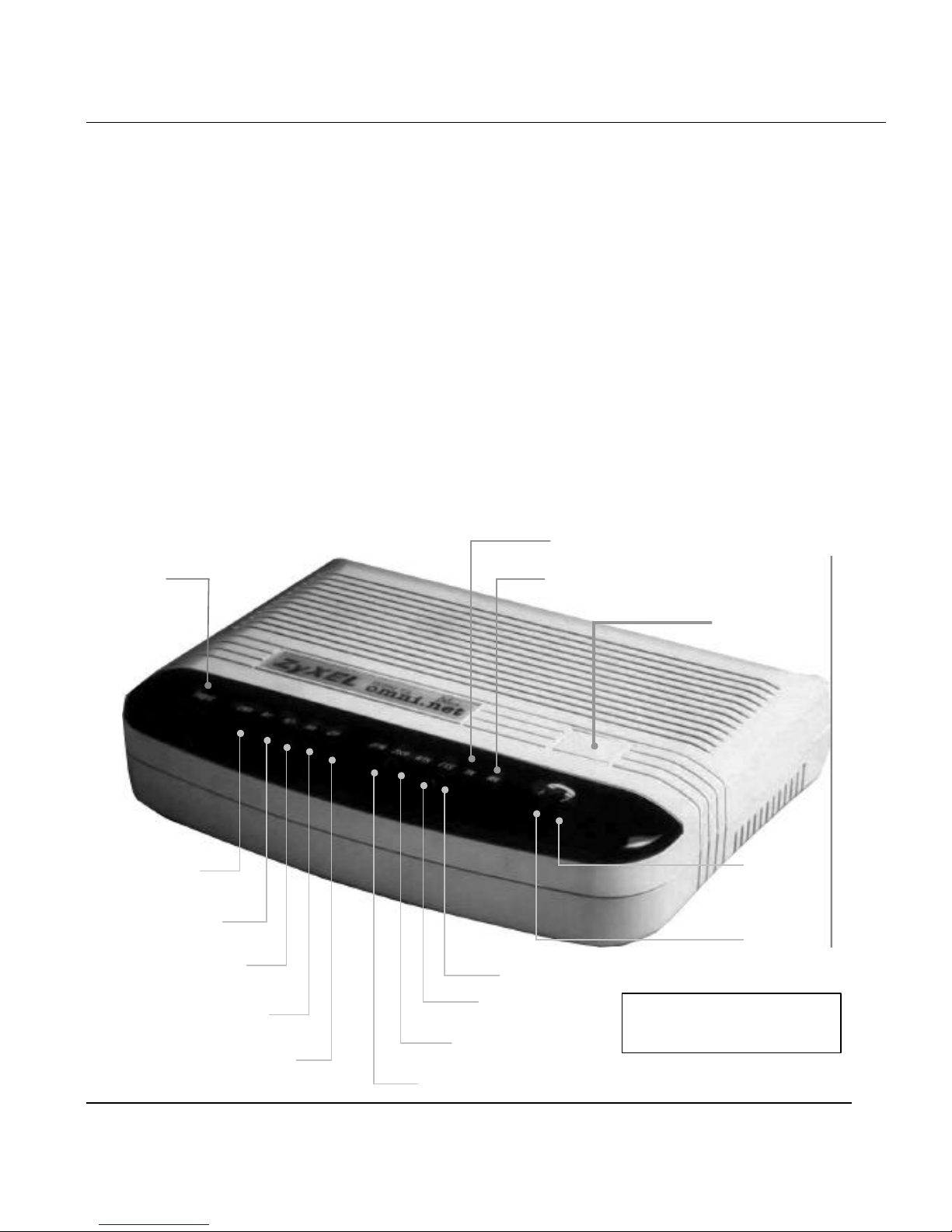
Front Panel Description
RX
LNK
B1
B2
AA
PWR
DTR
TX
CTS
RTS
DSR
Front Panel
Switch
CP
2
1
Phone 1 & Phone 2
for omni.net Plus only

omni.net Plus/D Quick Start Guide
1-2
Front Panel LEDs
LED Function Active Description
PWR
Power LED On When the power is turned ON.
LNK
Link LED On
Blinking
When the link with the local ISDN switch is active.
When attempting to make a connection.
B1
B1 Channel On When the B1 channel is established.
B2
B2 Channel On When the B2 channel is established.
AA
Auto -Answer On
Blinking
When your ISDN TA is in Auto Answer mode.
When your TA rings.
CP
Compression On
When Data Compression is being used over one or more
of the B Channels. Compression types are Hi/fn LZS
(formerly Stac) for PPP connections, and V.42bis for
V.120 or X.75 connections.
DTR
Data Terminal
Ready
On When the DTE or computer connected to the DTE
port signals that it is ready for communication by
establishing the RS-232 link.
DSR
Data Set
Ready
On
When the modem is ready for communication with the
DTE.
RTS Request To Send On
When the DTE has data to be sent to the remote modem.
The RTS signal is used in Hardware Handshaking.
CTS Clear To Send
On
When the modem is ready to receive data from the
remote modem. The CTS signal is used in Hardware
Handshaking.
TX
Transmit Data Blinking When the DTE/Computer transmits data to the
DTE port.
RX
Receive Data On When the DTE/Computer receives data from the
DTE port.
Phone 1 (for omni.net
Plus only)
On
When the POTS port 1 telephone/handset is off-hook.
Phone 2 (for omni.net
Plus only)
On
When the POTS port 2 telephone/handset is off-hook.

omni.net Plus/D Quick Start Guide
1-3
Front Panel Switch
When the TA is in command state, pressing the front panel button causes it to dial the default
phone number pre-stored in the NVRAM. The default number pointer to the telephone
directory is assigned by the AT*D n command.
When the TA is on-line, pressing the button will tear down the connection and bring it into
command state.
omni.net Plus/D Quick Start Guide
1-4
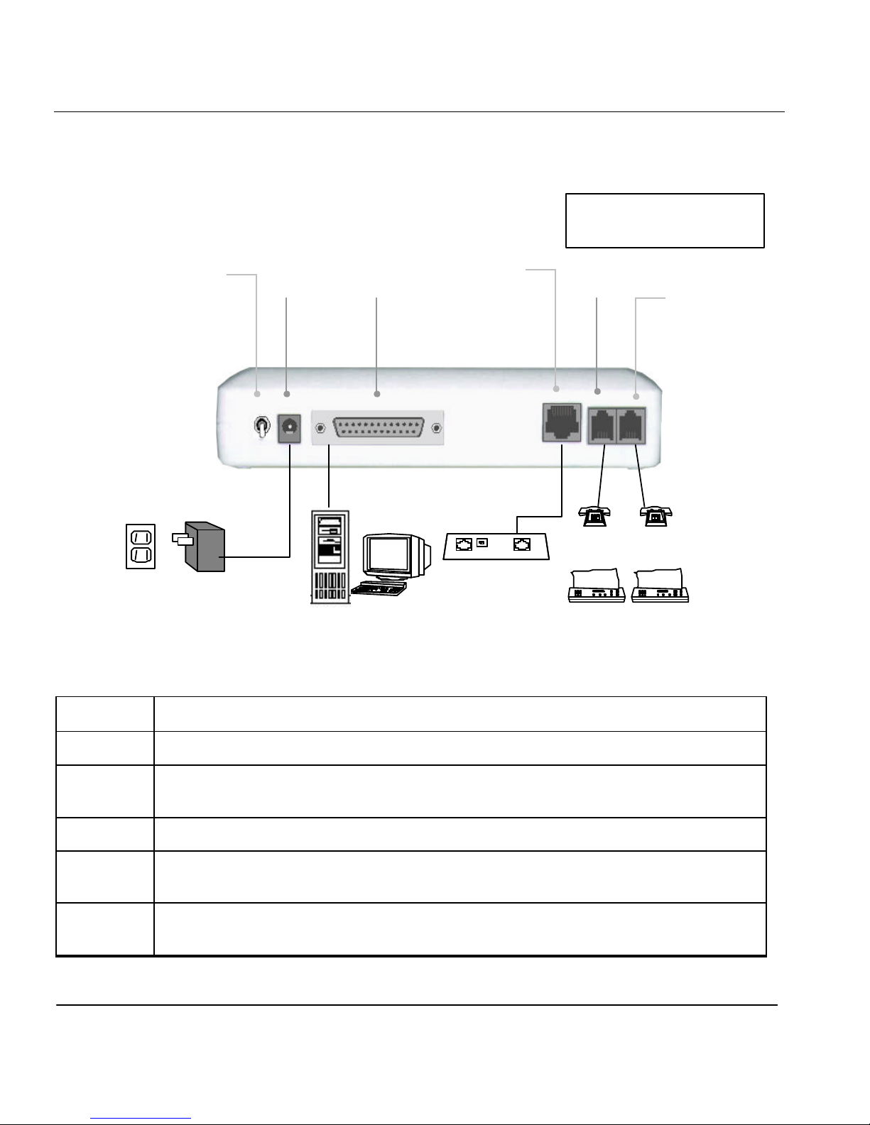
Back Panel Description and Connections (S/T Interface)
Back Panel Switch and Connectors
ON/OFF
Power ON/OFF switch
POWER Input terminal for power adapter.
To DTE Serial port DB-25 female connector for connection to the serial port of a DTE
(computer/terminal).
ISDN ISDN RJ-45 terminal jack; connects to a S/T interface or a U interface.
.
PHONE 1 RJ-11 terminal jack for analog adapter 1; for connecting to analog equipment. (phone,
fax, answering machine, etc.)
PHONE 2 RJ-11 terminal jack for analog adapter 2; for connecting to analog equipment. (phone,
fax, answering machine, etc.)
Tel
Tel
Fax Fax Power
Outlet
Power
Adapter
NT-1 Device
To DTE
Power
Input
Power ON/OFF
Switch Phone 2
Phone 1
ISDN
Phone 1 & Phone 2
for omni.net Plus only
Computer
omni.net Plus/D Quick Start Guide
1-5
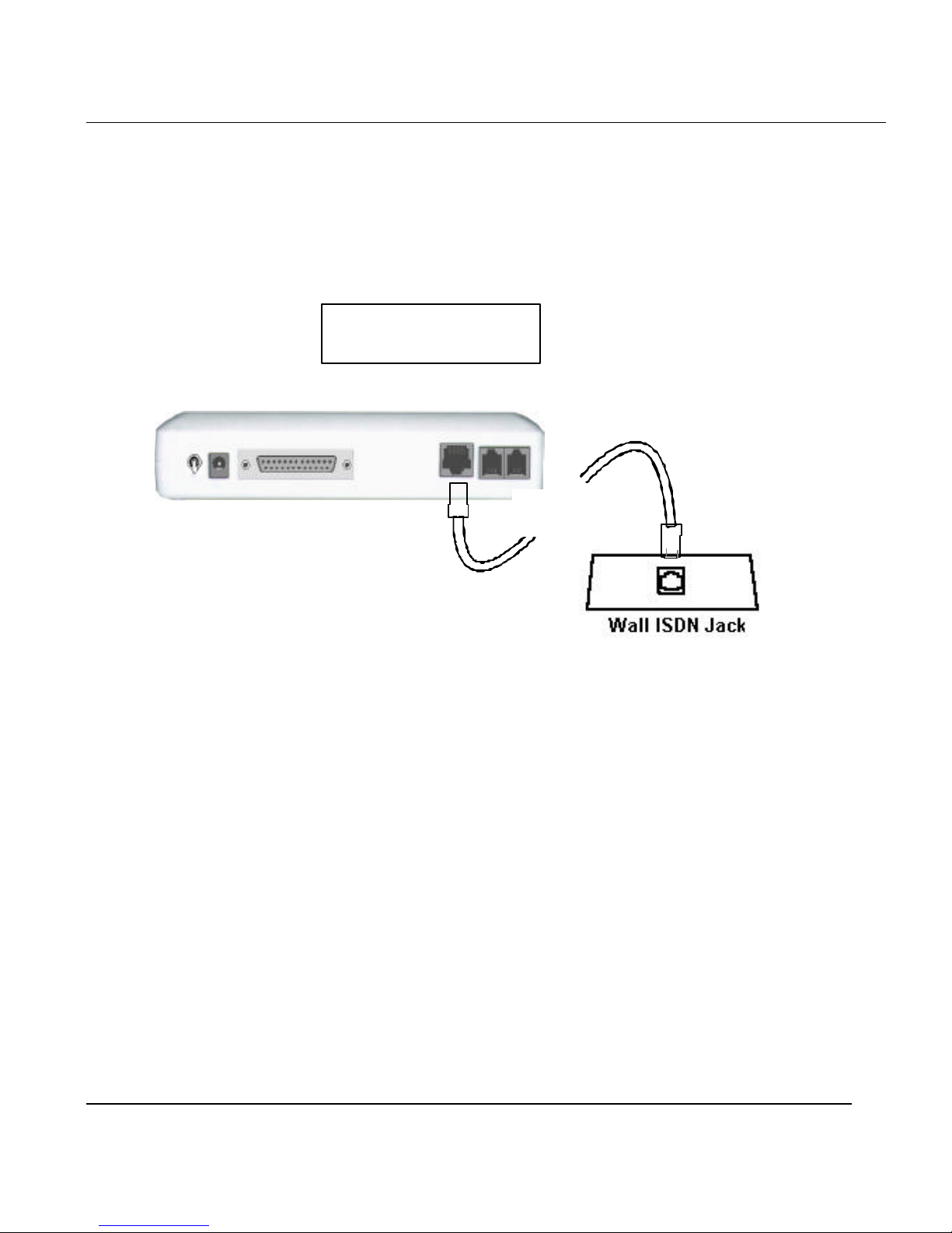
Connect Your omni.net Plus/D (U interface) to ISDN Line
Connect one end of the RJ-45 connectors to the “ISDN U” jack, and another end to
your wall jack, as the following illustration:
RJ-45
Phone 1 & Phone 2
for omni.net Plus only

omni.net Plus/D Quick Start Guide
1-6
Power On and Self Diagnostics
Once you have completed all of the installation steps above, flip the omni On/Off switch to the
ON (up) position.The unit starts a self-test sequence, where you should see a series of LED
lights blinking (LED, B1, B2, AA). After this cycle is complete, the PWR light should stay on.
If the test routine fails, the LNK LED flashes. Refer to your omni.net Plus/D Technical
Reference for more information on self-tests and error codes.
If you have a communication program loaded and active (connected to the same serial port as
the omni), you should see the DTR LED should be ON after the self-test.
 Loading...