

Page 1

OMC-2301
GEPON OLT Management Card
User’s Guide
Version 3.60
11/2 007
Edition 1
www.zyxel.com
Page 2

Page 3

About This User's Guide
About This User's Guide
Intended Audience
This manual is intended for people who want to configure the OMC-2301 GEPON (Gigabit
Ethernet Passive Optical Network) OLT (Optical Line Terminal) Management Card using the
web configurator or via commands. You should have at least a basic knowledge of TCP/IP
networking concepts and topology.
Related Documentation
• OLT-2300 User’s Guide
Refer to the OLT-2300 User’s Guide for directions on installation, connections,
maintenance, hardware trouble shooting and safety warnings.
• OLC-2301 Line Card User’s Guide
This user’s guide introduces the GEPON OLT line card and gives detailed information
about the line card features and hardware.
• ZyXEL Web Site
Please refer to www.zyxel.com
certifications.
for additional support documentation and product
User Guide Feedback
Help us help you. Send all User Guide-related comments, questions or suggestions for
improvement to the following address, or use e-mail instead. Thank you!
The Technical Writing Team,
ZyXEL Communications Corp.,
6 Innovation Road II,
Science-Based Industrial Park,
Hsinchu, 300, Taiwan.
E-mail: techwriters@zyxel.com.tw
OMC-2301 User’s Guide
3
Page 4

Document Conventions
Document Conventions
Warnings and Notes
These are how warnings and notes are shown in this User’s Guide.
1 Warnings tell you about things that could harm you or your device.
" Notes tell you other important information (for example, other things you may
need to configure or helpful tips) or recommendations.
Syntax Conventions
• The OMC-2301 GEPON OLT Management Card may be referred to as the “OMC-2301”,
the “OMC”, the “management card”, the “device” or the “system” in this User’s Guide.
• “OLT-2300” refers to the OLT-2300 system including the main chassis and their cards.
The OLT-2300 may be referred to as the “OLT”.
• The “OLC-2301”, the “OLC” or the “line card” refers to the OLC-2301 GEPON OLT
Line Card.
• The OLT-2300M is the OLT-2300 main chassis. It may be referred to as the “main
chassis”.
• The OPA-2300 is the power card. It may be referred to as the “power card”
• The OFC-2300 is the fan module. It may be referred to as the “fan module”
• Product labels, screen names, field labels and field choices are all in bold font.
• A key stroke is denoted by square brackets and uppercase text, for example, [ENTER]
means the “enter” or “return” key on your keyboard.
• “Enter” means for you to type one or more characters and then press the [ENTER] key.
“Select” or “choose” means for you to use one of the predefined choices.
• A right angle bracket ( > ) within a screen name denotes a mouse click. For example,
Maintenance > Log > Log Setting means you first click Maintenance in the navigation
panel, then the Log sub menu and finally the Log Setting tab to get to that screen.
• Units of measurement may denote the “metric” value or the “scientific” value. For
example, “k” for kilo may denote “1000” or “1024”, “M” for mega may denote “1000000”
or “1048576” and so on.
• “e.g.,” is a shorthand for “for instance”, and “i.e.,” means “that is” or “in other words”.
4
OMC-2301 User’s Guide
Page 5
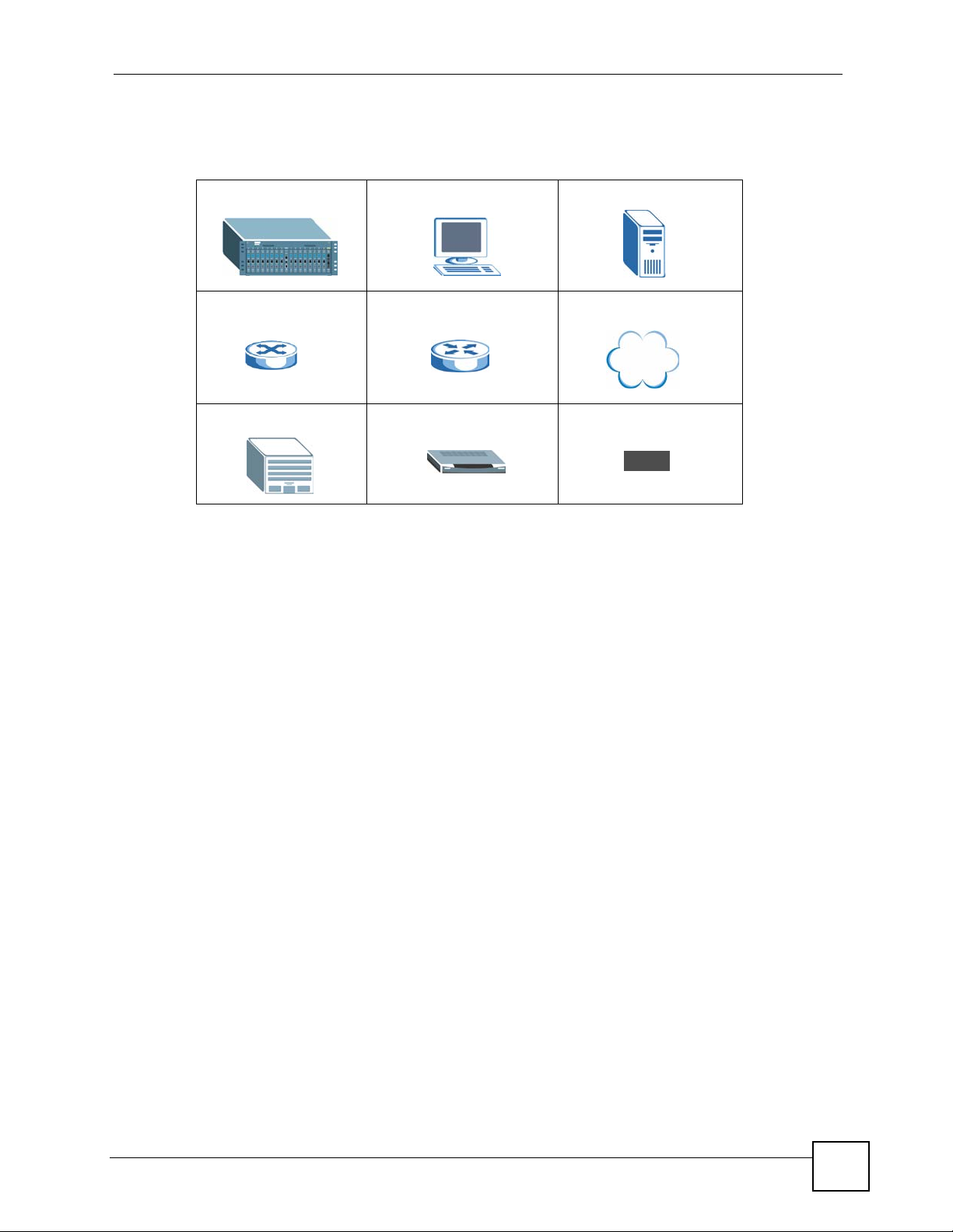
Icons Used in Figures
Figures in this User’s Guide may use the following generic icons.
OLT-2300 Computer Server
Switch Router Internet
Central Office/ISP ONU Splitter
Document Conventions
OMC-2301 User’s Guide
5
Page 6

Safety Warnings
Safety Warnings
1 For your safety, be sure to read and follow all warning notices and instructions.
For your safety, be sure to read and follow all warning notices and instructions.
• Do NOT use this product near water, for example, in a wet basement or near a swimming
pool.
• Do NOT expose your device to dampness, dust or corrosive liquids.
• Do NOT store things on the device.
• Do NOT install, use, or service this device during a thunderstorm. There is a remote risk
of electric shock from lightning.
• Connect ONLY suitable accessories to the device.
• Do NOT open the device or unit. Opening or removing covers can expose you to
dangerous high voltage points or other risks. ONLY qualified service personnel should
service or disassemble this device. Please contact your vendor for further information.
• Make sure to connect the cables to the correct ports.
• Place connecting cables carefully so that no one will step on them or stumble over them.
• Always disconnect all cables from this device before servicing or disassembling.
• Use ONLY an appropriate power adaptor or cord for your device.
• Connect the power adaptor or cord to the right supply voltage (for example, 110V AC in
North America or 230V AC in Europe).
• Do NOT allow anything to rest on the power adaptor or cord and do NOT place the
product where anyone can walk on the power adaptor or cord.
• Do NOT use the device if the power adaptor or cord is damaged as it might cause
electrocution.
• If the power adaptor or cord is damaged, remove it from the power outlet.
• Do NOT attempt to repair the power adaptor or cord. Contact your local vendor to order a
new one.
• Do not use the device outside, and make sure all the connections are indoors. There is a
remote risk of electric shock from lightning.
• Do NOT obstruct the device ventilation slots, as insufficient airflow may harm your
device.
• Refer also to the OLT-2300 User’s Guide and follow all safety warnings for installation,
connections, maintenance and hardware trouble shooting.
• Warning! To avoid risk of electric shock, remove only one card at a time and do not place
fingers or objects inside the chassis. Cover empty slots with slot covers.
6
This product is recyclable. Dispose of it properly.
OMC-2301 User’s Guide
Page 7

Safety Warnings
OMC-2301 User’s Guide
7
Page 8

Safety Warnings
8
OMC-2301 User’s Guide
Page 9

Contents Overview
Contents Overview
Introduction ............................................................................................................................ 25
Introducing the OMC ................................................................................................................. 27
Hardware ................................................................................................................................... 31
Basic Setup ............................................................................................................................35
The Web Configurator ............................................................................................................... 37
Initial Setup Example ................................................................................................................. 43
System Status and Port Statistics ..............................................................................................47
Basic Setting ............................................................................................................................. 57
Advanced ................................................................................................................................ 77
Classifier Filter Profile ................................................................................................................ 79
VLAN Profile .............................................................................................................................. 83
Priority Profile ............................................................................................................................ 93
Static MAC Forward Setup ........................................................................................................ 97
Destination Filter ...................................................................................................................... 101
Port Authentication .................................................................................................................. 105
Access Control ........................................................................................................................ 109
Management ......................................................................................................................... 121
Maintenance ............................................................................................................................ 123
Diagnostic ................................................................................................................................ 131
Syslog ...................................................................................................................................... 133
MAC Table ............................................................................................................................... 137
IGMP Table .............................................................................................................................. 141
Commands, Troubleshooting and Specifications ............................................................143
Introducing the Commands ..................................................................................................... 145
Command Examples ...............................................................................................................175
Troubleshooting ....................................................................................................................... 191
Product Specifications ............................................................................................................. 203
Appendix and Index .............................................................................................................207
OMC-2301 User’s Guide
9
Page 10

Contents Overview
10
OMC-2301 User’s Guide
Page 11

Table of Contents
Table of Contents
About This User's Guide ..........................................................................................................3
Document Conventions............................................................................................................4
Safety Warnings........................................................................................................................6
Contents Overview ...................................................................................................................9
Table of Contents.................................................................................................................... 11
List of Figures ......................................................................................................................... 19
List of Tables...........................................................................................................................23
Part I: Introduction................................................................................. 25
Chapter 1
Introducing the OMC ..............................................................................................................27
1.1 Overview .............................................................................................................................. 27
1.2 Applications ......................................................................................................................... 27
1.3 Ways to Manage the OMC .................................................................................................. 28
1.4 Good Habits for Managing the OMC ................................................................................... 28
Chapter 2
Hardware.................................................................................................................................. 31
2.1 Front Panel .......................................................................................................................... 31
2.2 LEDs .................................................................................................................................... 31
2.3 Hardware Connection ......................................................................................................... 32
2.3.1 Console Port .............................................................................................................. 32
2.3.2 Alarm Port Pin Assignments ...................................................................................... 32
2.3.3 Power Connector ....................................................................................................... 33
Part II: Basic Setup ................................................................................ 35
Chapter 3
The Web Configurator ............................................................................................................37
3.1 Introduction .......................................................................................................................... 37
OMC-2301 User’s Guide
11
Page 12

Table of Contents
3.2 System Login ....................................................................................................................... 37
3.3 The Status Screen ............................................................................................................... 38
3.3.1 Change Your Password ............................................................................................. 40
3.4 Device Lockout .................................................................................................................... 40
3.5 Resetting the OMC .............................................................................................................. 41
3.5.1 Reload the Configuration File ..................................................................................... 41
3.6 Logging Out of the Web Configurator .................................................................................. 42
3.7 Help ..................................................................................................................................... 42
Chapter 4
Initial Setup Example..............................................................................................................43
4.1 Overview .............................................................................................................................. 43
4.2 Connecting the Devices ....................................................................................................... 43
4.3 Creating a Service Profile .................................................................................................... 44
4.4 Testing the Internet Connection ........................................................................................... 45
Chapter 5
System Status and Port Statistics.........................................................................................47
5.1 Overview .............................................................................................................................. 47
5.2 Port Status Summary .......................................................................................................... 47
5.2.1 EPON Info ................................................................................................................. 48
5.2.2 EPON Details ............................................................................................................49
5.2.3 Ethernet Port Details ................................................................................................. 55
Chapter 6
Basic Setting .......................................................................................................................... 57
6.1 Overview .............................................................................................................................. 57
6.2 System Information ............................................................................................................. 57
6.3 General Setup .................................................................................................................... 59
6.4 IP Setup .............................................................................................................................. 61
6.4.1 Management IP Address ............................................................................................ 61
6.5 Port Setup ........................................................................................................................... 62
6.6 IGMP Snooping ................................................................................................................... 63
6.6.1 IGMP Proxy ................................................................................................................ 63
6.7 DBA (Dynamic Bandwidth Allocation) ................................................................................. 64
6.8 EPON Common Setup ...................................................................................................... 65
6.9 ONU Setup ......................................................................................................................... 67
6.10 EPON Profile .................................................................................................................... 69
6.11 Introduction to VLANs ....................................................................................................... 73
6.11.1 Port-based VLANs .................................................................................................... 74
6.12 4-Port ONU Profile ............................................................................................................ 74
12
OMC-2301 User’s Guide
Page 13

Table of Contents
Part III: Advanced................................................................................... 77
Chapter 7
Classifier Filter Profile............................................................................................................ 79
7.1 Overview .............................................................................................................................. 79
7.2 Classifier Filter Profile Setup .............................................................................................. 79
7.2.1 Example: Classifier Filter Profile ................................................................................ 81
Chapter 8
VLAN Profile............................................................................................................................ 83
8.1 Introduction to IEEE 802.1Q Tagged VLANs ....................................................................... 83
8.1.1 Forwarding Tagged and Untagged Frames ................................................................ 83
8.2 VLAN Stacking ..................................................................................................................... 84
8.2.1 VLAN Stacking Example ............................................................................................ 84
8.3 VLAN Tag Format ................................................................................................................ 85
8.3.1 Frame Format ............................................................................................................ 85
8.4 Configuring a VLAN Profile ................................................................................................. 86
8.4.1 VLAN Profile: Example ............................................................................................... 89
8.4.2 VLAN Profile: Example 2 ............................................................................................ 90
Chapter 9
Priority Profile ......................................................................................................................... 93
9.1 Priority Profile Overview ...................................................................................................... 93
9.2 Configuring a Priority Profile ............................................................................................... 93
9.2.1 Example: Priority Profile ............................................................................................. 96
Chapter 10
Static MAC Forward Setup..................................................................................................... 97
10.1 Overview ............................................................................................................................ 97
10.2 Static MAC Forwarding Status .......................................................................................... 97
10.3 Configuring Static MAC Forwarding ................................................................................ 98
Chapter 11
Destination Filter................................................................................................................... 101
11.1 Overview .......................................................................................................................... 101
11.2 Destination Filter Status .................................................................................................. 101
11.3 Destination Filter Setup ................................................................................................... 102
11.3.1 Example: Destination Filter .................................................................................... 103
Chapter 12
Port Authentication............................................................................................................... 105
12.1 Overview .......................................................................................................................... 105
12.1.1 RADIUS .................................................................................................................105
OMC-2301 User’s Guide
13
Page 14

Table of Contents
12.2 Configuring Port Authentication ...................................................................................... 106
12.2.1 Activating IEEE 802.1x Security ............................................................................ 106
12.2.2 Configuring RADIUS Server Settings .................................................................... 107
Chapter 13
Access Control...................................................................................................................... 109
13.1 About Access Control ....................................................................................................109
13.2 The Access Control Main Screen .................................................................................... 109
13.3 About SNMP ....................................................................................................................110
13.3.1 Supported MIBs ...................................................................................................... 111
13.3.2 SNMP Traps ............................................................................................................111
13.3.3 Configuring SNMP .................................................................................................112
13.4 Login Accounts ...............................................................................................................112
13.5 SSH Overview ..................................................................................................................113
13.6 How SSH works ................................................................................................................114
13.7 SSH Implementation on the OMC ....................................................................................115
13.7.1 Requirements for Using SSH ..................................................................................115
13.8 Introduction to HTTPS ......................................................................................................115
13.9 HTTPS Example ...............................................................................................................116
13.9.1 Internet Explorer Warning Messages ......................................................................116
13.9.2 Netscape Navigator Warning Messages .................................................................116
13.9.3 The Main Screen .....................................................................................................117
13.10 Service Access Control .................................................................................................118
13.11 Remote Management ....................................................................................................119
Part IV: Management............................................................................ 121
Chapter 14
Maintenance .......................................................................................................................... 123
14.1 The Main Maintenance Screen ....................................................................................... 123
14.2 Load Factory Defaults .....................................................................................................123
14.3 Reboot System ................................................................................................................ 124
14.4 Remote ONU Firmware Upgrade ................................................................................... 124
14.5 Line Card Reset .............................................................................................................. 125
14.6 ONU Device Reset .........................................................................................................126
14.7 OMC Firmware Upgrade ................................................................................................ 126
14.8 Restore Configuration ..................................................................................................... 127
14.9 Backup Configuration .....................................................................................................127
14.10 FTP Command Line ...................................................................................................... 128
14.10.1 Filename Conventions ......................................................................................... 128
14.10.2 FTP Command Line Procedure .......................................................................... 129
14
OMC-2301 User’s Guide
Page 15

Table of Contents
14.10.3 GUI-based FTP Clients ........................................................................................ 129
14.10.4 FTP Restrictions ................................................................................................... 130
Chapter 15
Diagnostic.............................................................................................................................. 131
15.1 Diagnostic ....................................................................................................................... 131
15.2 Saving Logs ..................................................................................................................... 132
Chapter 16
Syslog .................................................................................................................................... 133
16.1 Overview .......................................................................................................................... 133
16.2 Syslog Setup ................................................................................................................. 133
16.3 Syslog Server Setup ....................................................................................................... 134
Chapter 17
MAC Table..............................................................................................................................137
17.1 MAC Table Overview ...................................................................................................... 137
17.2 Viewing the MAC Table ................................................................................................... 138
Chapter 18
IGMP Table.............................................................................................................................141
18.1 Displaying IGMP Table .................................................................................................. 141
Part V: Commands, Troubleshooting and Specifications ................ 143
Chapter 19
Introducing the Commands .................................................................................................145
19.1 Overview .......................................................................................................................... 145
19.1.1 Configuration File ................................................................................................... 145
19.2 Accessing the CLI .......................................................................................................... 145
19.2.1 Multiple Login ......................................................................................................... 146
19.2.2 The Console Port ................................................................................................... 146
19.2.3 Telnet ..................................................................................................................... 147
19.2.4 SSH ........................................................................................................................ 147
19.3 The Login Screen ........................................................................................................... 148
19.4 Command Syntax Conventions ....................................................................................... 148
19.5 Changing the Password .................................................................................................. 148
19.6 Command Modes ............................................................................................................ 149
19.7 Getting Help ..................................................................................................................... 150
19.7.1 List of Available Commands ................................................................................... 150
19.7.2 Detailed Command Information ............................................................................. 151
OMC-2301 User’s Guide
15
Page 16

Table of Contents
19.8 Using Command History .................................................................................................. 151
19.9 Saving Your Configuration ............................................................................................... 152
19.9.1 Logging Out ............................................................................................................ 152
19.10 Command Summary ...................................................................................................... 152
19.10.1 User Mode ............................................................................................................ 152
19.10.2 Enable Mode ........................................................................................................ 155
19.10.3 General Configuration Mode ................................................................................ 159
19.10.4 classifier-filter-profile Commands ......................................................................... 165
19.10.5 epon-common Commands ................................................................................... 166
19.10.6 epon-onu4-profile Commands .............................................................................. 167
19.10.7 epon-profile Commands ....................................................................................... 168
19.10.8 onu Commands .................................................................................................... 170
19.10.9 priority-profile Commands .................................................................................... 171
19.10.10 vlan-profile Commands ...................................................................................... 171
Chapter 20
Command Examples.............................................................................................................175
20.1 Overview .......................................................................................................................... 175
20.2 show Commands .............................................................................................................175
20.2.1 show epon .............................................................................................................. 175
20.2.2 show epon-counter ................................................................................................. 176
20.2.3 show epon-counter onu .......................................................................................... 177
20.2.4 show hardware-monitor .......................................................................................... 177
20.2.5 show ip ................................................................................................................... 178
20.2.6 show system-information ....................................................................................... 178
20.3 ip address ........................................................................................................................ 179
20.4 ping ................................................................................................................................. 179
20.5 traceroute ........................................................................................................................ 180
20.6 epon-common Commands .............................................................................................. 180
20.7 epon-profile Commands .................................................................................................. 181
20.8 Configuration File Maintenance ...................................................................................... 183
20.8.1 Backing up Configuration ....................................................................................... 183
20.8.2 Using a Different Configuration File ....................................................................... 183
20.8.3 Restoring Configuration ........................................................................................ 184
20.8.4 Resetting to the Factory Default ............................................................................. 184
20.9 no Command Examples .................................................................................................. 185
20.9.1 no port-access-authenticator .................................................................................. 185
20.9.2 no ssh ..................................................................................................................... 185
20.10 priority-profile Commands ............................................................................................. 186
20.11 onu Commands .............................................................................................................. 187
20.12 vlan-profile Commands .................................................................................................. 188
Chapter 21
Troubleshooting.................................................................................................................... 191
16
OMC-2301 User’s Guide
Page 17

Table of Contents
21.1 Power, Hardware Connections, and LEDs ...................................................................... 191
21.2 OMC Access and Login ................................................................................................... 192
21.3 Management Lockout ...................................................................................................... 194
21.4 A Line Card Does Not Become Active ............................................................................. 194
21.5 Resetting the Defaults ..................................................................................................... 195
21.5.1 Resetting the Defaults Via CLI Command ............................................................. 195
21.5.2 Reload the Configuration File ................................................................................. 195
21.5.3 Recovering the Firmware ....................................................................................... 196
21.6 Pop-up Windows, JavaScripts and Java Permissions ..................................................... 197
21.6.1 Internet Explorer Pop-up Blockers ......................................................................... 197
21.6.2 JavaScripts .............................................................................................................200
21.6.3 Java Permissions ................................................................................................... 201
Chapter 22
Product Specifications.........................................................................................................203
Part VI: Appendix and Index ............................................................... 207
Appendix A Legal Information .............................................................................................. 209
Appendix B Customer Support .............................................................................................213
Index....................................................................................................................................... 219
OMC-2301 User’s Guide
17
Page 18

Table of Contents
18
OMC-2301 User’s Guide
Page 19

List of Figures
List of Figures
Figure 1 Network Example .................................................................................................................... 27
Figure 2 FTTH Network Example .......................................................................................................... 28
Figure 3 FTTB Network Example .......................................................................................................... 28
Figure 4 OMC Front Panel ................................................................................................................... 31
Figure 5 Alarm Connector Pin Layout ................................................................................................... 33
Figure 6 Web Configurator: Login ......................................................................................................... 38
Figure 7 Web Configurator: Home Screen (Status) ..............................................................................38
Figure 8 Change Administrator Login Password ................................................................................... 40
Figure 9 Resetting the Device: Via the Console Port ............................................................................ 42
Figure 10 Web Configurator: Logout Screen ......................................................................................... 42
Figure 11 Initial Setup: Network Example .............................................................................................. 43
Figure 12 Status .................................................................................................................................... 47
Figure 13 Status: EPON Info ................................................................................................................. 48
Figure 14 Status: EPON Info: EPON Details ........................................................................................ 50
Figure 15 Status: Port Details ................................................................................................................ 56
Figure 16 System Info ........................................................................................................................... 58
Figure 17 General Setup ....................................................................................................................... 60
Figure 18 IP Setup ................................................................................................................................. 61
Figure 19 Port Setup ............................................................................................................................. 62
Figure 20 IGMP Proxy Network Example ............................................................................................... 64
Figure 21 EPON Setup ......................................................................................................................... 65
Figure 22 ONU Setup ............................................................................................................................ 67
Figure 23 EPON Profile ......................................................................................................................... 70
Figure 24 4-Port ONU Profile ................................................................................................................ 75
Figure 25 Classifier Filter Profile Setup ................................................................................................. 79
Figure 26 Classifier Filter Profile: Example ........................................................................................... 81
Figure 27 VLAN Stacking Example ....................................................................................................... 85
Figure 28 EPON VLAN Profile Setup .................................................................................................... 87
Figure 29 VLAN Network Example 1 ...................................................................................................... 90
Figure 30 VLAN Profile: Example 1 ....................................................................................................... 90
Figure 31 VLAN Network Example 2 ..................................................................................................... 90
Figure 32 VLAN Profile: Example 2 ....................................................................................................... 91
Figure 33 VLAN Profile: Example 2: Classifier Filter Profile ..................................................................91
Figure 34 Priority Profile ........................................................................................................................ 94
Figure 35 Priority Profile: Example ........................................................................................................ 96
Figure 36 Static MAC Forwarding Status ................................................................................................ 97
Figure 37 Static MAC Forwarding .......................................................................................................... 98
Figure 38 Destination Filter Status ...................................................................................................... 101
OMC-2301 User’s Guide
19
Page 20

List of Figures
Figure 39 Destination Filter: DA Filter ................................................................................................. 102
Figure 40 Destination Filter: Example ................................................................................................. 103
Figure 41 RADIUS Server Network Example .................................................................................... 105
Figure 42 Port Authentication .............................................................................................................. 106
Figure 43 Port Authentication: 802.1x ................................................................................................. 106
Figure 44 Port Authentication: RADIUS .............................................................................................. 107
Figure 45 Access Control .....................................................................................................................110
Figure 46 SNMP Management Model ..................................................................................................110
Figure 47 Access Control: SNMP .........................................................................................................112
Figure 48 Access Control: Logins .........................................................................................................113
Figure 49 SSH Communication Example ..............................................................................................114
Figure 50 How SSH Works ....................................................................................................................114
Figure 51 HTTPS Implementation .........................................................................................................115
Figure 52 Security Alert Dialog Box (Internet Explorer) .........................................................................116
Figure 53 Security Certificate 1 (Netscape) ...........................................................................................117
Figure 54 Security Certificate 2 (Netscape) ...........................................................................................117
Figure 55 Example: Lock Denoting a Secure Connection ....................................................................118
Figure 56 Access Control: Service Access Control ..............................................................................118
Figure 57 Access Control: Remote Management .................................................................................119
Figure 58 Maintenance ....................................................................................................................... 123
Figure 59 Load Factory Default: Conformation ................................................................................... 123
Figure 60 Reboot System: Confirmation ............................................................................................. 124
Figure 61 Maintenance: Remote Firmware Upgrade .......................................................................... 124
Figure 62 Maintenance: Line Card Reset ............................................................................................ 125
Figure 63 Maintenance: ONU Device Reset .......................................................................................126
Figure 64 Firmware Upgrade .............................................................................................................. 127
Figure 65 Restore Configuration ......................................................................................................... 127
Figure 66 Backup Configuration .......................................................................................................... 128
Figure 67 Diagnostic ............................................................................................................................ 131
Figure 68 Syslog .................................................................................................................................. 134
Figure 69 Syslog: Server Setup ........................................................................................................... 134
Figure 70 MAC Table Flowchart .......................................................................................................... 138
Figure 71 MAC Table ........................................................................................................................... 138
Figure 72 IGMP Table .......................................................................................................................... 141
Figure 73 boot config Command Example .......................................................................................... 183
Figure 74 CLI: reload config Command Example ................................................................................ 184
Figure 75 Reload the Configuration File: Via Console Port ................................................................. 196
Figure 76 Example Xmodem Upload .................................................................................................... 197
Figure 77 Pop-up Blocker ..................................................................................................................... 198
Figure 78 Internet Options .................................................................................................................... 198
Figure 79 Internet Options .................................................................................................................... 199
Figure 80 Pop-up Blocker Settings ....................................................................................................... 199
Figure 81 Internet Options .................................................................................................................... 200
20
OMC-2301 User’s Guide
Page 21

List of Figures
Figure 82 Security Settings - Java Scripting ......................................................................................... 201
Figure 83 Security Settings - Java ........................................................................................................ 202
Figure 84 Java (Sun) ............................................................................................................................ 202
Figure 85 Console Cable RJ-11 Male Connector ................................................................................. 205
Figure 86 Console Cable DB-9 Female Connector .............................................................................. 206
OMC-2301 User’s Guide
21
Page 22

List of Figures
22
OMC-2301 User’s Guide
Page 23

List of Tables
List of Tables
Table 1 LEDs ......................................................................................................................................... 31
Table 2 Port Connection ........................................................................................................................ 32
Table 3 Alarm Connector Pin Assignments ........................................................................................... 33
Table 4 Navigation Panel Sub-links Overview ....................................................................................... 38
Table 5 Web Configurator Screen Sub-links Details .............................................................................. 39
Table 6 Navigation Panel Links ............................................................................................................. 39
Table 7 Status ........................................................................................................................................ 47
Table 8 Status: EPON Info ..................................................................................................................... 49
Table 9 Status: EPON Info: EPON Details ............................................................................................. 52
Table 10 Status: Port Details ................................................................................................................. 56
Table 11 System Info ............................................................................................................................. 58
Table 12 General Setup ......................................................................................................................... 60
Table 13 IP Setup .................................................................................................................................. 61
Table 14 Port Setup ............................................................................................................................... 62
Table 15 EPON Setup ........................................................................................................................... 66
Table 16 ONU Setup .............................................................................................................................. 67
Table 17 EPON Profile ........................................................................................................................... 70
Table 18 4-Port ONU Profile .................................................................................................................. 75
Table 19 Classifier Filter Profile Setup ................................................................................................... 80
Table 20 VLAN Tag Format ................................................................................................................... 85
Table 21 Single and Double Tagged 802.11Q Frame Format ............................................................... 85
Table 22 802.1Q Frame ......................................................................................................................... 86
Table 23 EPON VLAN Profile Setup ...................................................................................................... 87
Table 24 Priority Profile .......................................................................................................................... 94
Table 25 Common Ethernet Types Numbers ......................................................................................... 95
Table 26 Common Protocol Names and Numbers ................................................................................ 96
Table 27 Static MAC Forwarding Status ................................................................................................ 97
Table 28 Static MAC Forwarding ........................................................................................................... 98
Table 29 Destination Filter Status ........................................................................................................ 101
Table 30 Destination Filter: DA Filter ................................................................................................... 102
Table 31 Port Authentication: 802.1x ................................................................................................... 107
Table 32 Port Authentication: RADIUS ................................................................................................ 107
Table 33 Access Control Overview ...................................................................................................... 109
Table 34 SNMP Commands .................................................................................................................111
Table 35 SNMP Traps ...........................................................................................................................111
Table 36 Access Control: SNMP ..........................................................................................................112
Table 37 Access Control: Logins ..........................................................................................................113
Table 38 Access Control: Service Access Control ................................................................................118
OMC-2301 User’s Guide
23
Page 24

List of Tables
Table 39 Access Control: Remote Management ..................................................................................119
Table 40 Filename Conventions .......................................................................................................... 128
Table 41 Diagnostic ............................................................................................................................. 131
Table 42 Syslog Severity Levels .......................................................................................................... 133
Table 43 Syslog ................................................................................................................................... 134
Table 44 Syslog: Server Setup ............................................................................................................ 135
Table 45 MAC Table ............................................................................................................................ 138
Table 46 IGMP Table ........................................................................................................................... 141
Table 47 Sub Configuration Modes ..................................................................................................... 149
Table 48 Command Summary: User Mode ........................................................................................ 152
Table 49 Command Summary: Enable Mode ...................................................................................... 155
Table 50 Command Summary: Configuration Mode ............................................................................ 159
Table 51 classifier-filter-profile Commands .......................................................................................... 165
Table 52 epon-common Commands .................................................................................................... 166
Table 53 epon-onu4-profile Commands .............................................................................................. 167
Table 54 epon-profile Commands ........................................................................................................ 168
Table 55 onu Commands ..................................................................................................................... 170
Table 56 priority-profile Commands ..................................................................................................... 171
Table 57 vlan-profile Commands ......................................................................................................... 172
Table 58 Default Settings ..................................................................................................................... 203
Table 59 OMC-2301 Specifications ..................................................................................................... 203
Table 60 OLT-2300 Features ............................................................................................................... 204
Table 61 Console Cable Connector Pin Assignments ......................................................................... 206
24
OMC-2301 User’s Guide
Page 25

PART I
Introduction
Introducing the OMC (27)
Hardware (31)
25
Page 26

26
Page 27
CHAPTER 1
Introducing the OMC
This chapter introduces the OMC and the ways you can manage the OMC.
1.1 Overview
The OLT-2300 is a manageable optical line terminal (OLT), which is capable of providing
network access to customers at distances up to 20 km.
The OLT-2300 allows service providers to easily implement FTTH (Fiber To The Home)
infrastructure offering reliable high-speed network access to their subscribers over optical
fiber through ONUs (Optical Network Units).
The following shows an example network.
Figure 1 Network Example
Ethernet
The OMC-2301 (GEPON OLT Management Card) centralizes the management of all of the
GEPON OLT line cards. You can configure and maintain the OLT line cards through the OLT
management card; thus eliminating the need to connect to each line card individually.
With its built-in web configurator, managing and configuring the OMC is easy. In addition, the
OMC can also be managed via Telnet, a terminal emulator program on the console port, or by
third-party SNMP management.
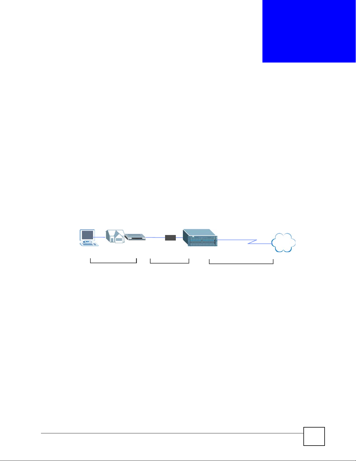
1.2 Applications
In the following figure shows an FTTH (Fiber to the Home) examples using the OLT-2300.
The OLT-2300 is located at the Central Office (CO) and connected to the Internet. Three
ONUs at the residential homes connect to a fiber port on the OLT-2300 through a fiber splitter.
ONU
Fiber
Internet
OLT
Ethernet or Fiber
OMC-2301 User’s Guide
27
Page 28
Chapter 1 Introducing the OMC
Figure 2 FTTH Network Example
ONU
OLT
Internet
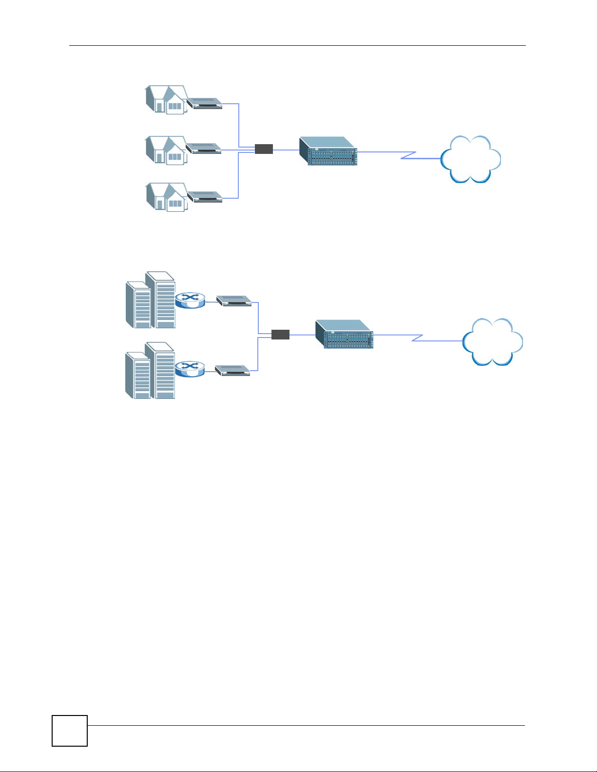
In the following FTTB (Fiber To The Building) example, the OLT-2300 provides Internet
access for tenants in the two buildings through fiber connections.
Figure 3 FTTB Network Example
VDSL
ONU
OLT
Internet
1.3 Ways to Manage the OMC
Use any of the following methods to manage the OMC.
• Web Configurator. This is recommended for everyday management of the OMC using a
(supported) web browser.
• Command Line Interface. Line commands are mostly used for troubleshooting by service
engineers.
• FTP for firmware upgrades and configuration backup/restore.
• SNMP. The device can be monitored by an SNMP manager. See the SNMP chapter in this
User’s Guide.
1.4 Good Habits for Managing the OMC
Do the following things regularly to make the OMC more secure and to manage the OMC
more effectively.
• Change the password. Use a password that’s not easy to guess and that consists of
different types of characters, such as numbers and letters.
• Write down the password and put it in a safe place.
28
OMC-2301 User’s Guide
Page 29

Chapter 1 Introducing the OMC
• Back up the configuration (and make sure you know how to restore it). Restoring an
earlier working configuration may be useful if the device becomes unstable or even
crashes. If you forget your password, you will have to reset the OMC to its factory default
settings. If you backed up an earlier configuration file, you would not have to totally reconfigure the OMC. You could simply restore your last configuration.
OMC-2301 User’s Guide
29
Page 30

Chapter 1 Introducing the OMC
30
OMC-2301 User’s Guide
Page 31
CHAPTER 2
Hardware
This chapter shows you how to make the hardware connections.
" Refer to the OLT-2300 User’s Guide for directions and safety warnings on
installing the management card.
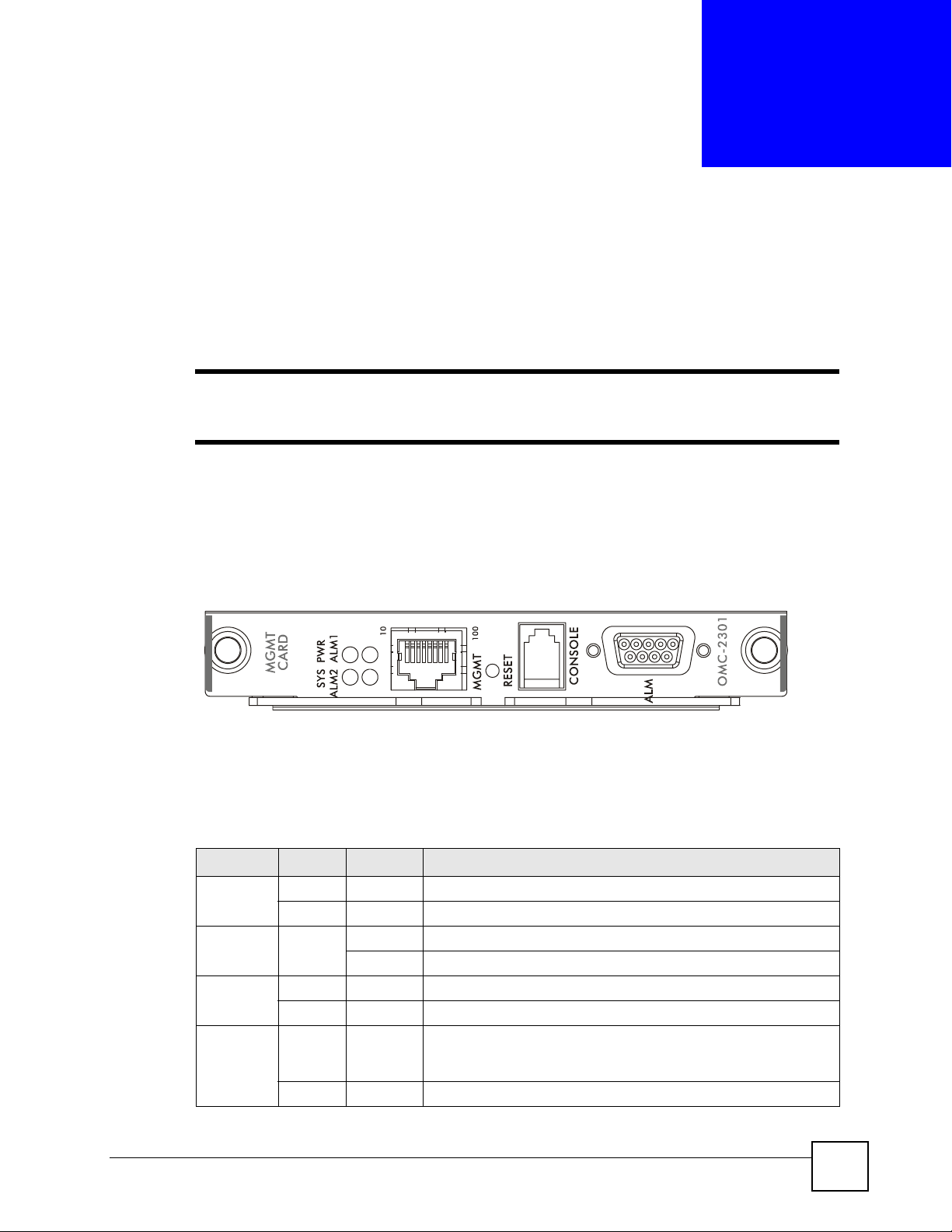
2.1 Front Panel
The figure below shows the front panel of the OMC.
Figure 4 OMC Front Panel
2.2 LEDs
The following table describes the LEDs on the OMC.
Table 1 LEDs
LED COLOR STATUS DESCRIPTION
PWR Green On The OMC is receiving power.
SYS Green On The OMC is ready and is functioning properly.
ALM 1 Red On There is a hardware failure.
ALM 2 Red On A traffic error (such as Bit Error Rate (BER), Dying Gasp, Errored
Off The OMC is not receiving power.
Blinking The OMC is rebooting.
Off The OMC is functioning normally.
Frames, bad encryption key or LLID mismatch) occurs on a line
card.
Off There is no traffic error on a line card.
OMC-2301 User’s Guide
31
Page 32

Chapter 2 Hardware
Table 1 LEDs (continued)
LED COLOR STATUS DESCRIPTION
MGMT Port
10 Green On The link to a 10 Mbps Ethernet network is up.
Blinking The port is receiving or transmitting data at 10 Mbps.
Off This port is not connected to an Ethernet device.
100 Amber On The link to a 100 Mbps Ethernet network is up.
Blinking The port is receiving or transmitting data. at 100 Mbps.
Off This port is not connected to an Ethernet device.
2.3 Hardware Connection
" Install the OMC before you make the hardware connections. Refer to the OLT-
2300 User’s Guide for installation instructions.
The following table describes the port labels on the front panel.
Table 2 Port Connection
PORT DESCRIPTION
CONSOLE Only connect this port if you want to configure the OMC using the command line
ALM Connect this DB-9 connector to alarm input and alarm output terminals on other
MGMT Connect to a computer using an RJ-45 Ethernet cable for local configuration of the
2.3.1 Console Port
For local management using the CLI (Command Line Interface) commands, you can use a
computer with terminal emulation software configured to the following parameters:
• VT100 terminal emulation
• 115200 bps
• No parity, 8 data bits, 1 stop bit
• No flow control
Connect the male mini-RJ11 end of the console cable to the console port of the OMC. Connect
the female end to a serial port (COM1, COM2 or other COM port) of your computer.
interface (CLI) via the console port.
pieces of equipment (see Section 2.3.2 on page 32 for details).
OMC.
2.3.2 Alarm Port Pin Assignments
This section explains the connections to the ALM port on the management card. The ALM
port is a male 9-pin connector.
32
OMC-2301 User’s Guide
Page 33

Chapter 2 Hardware
Figure 5 Alarm Connector Pin Layout
The ALM port has input pins and output pins.
Connect the alarm input pins to another piece of equipment so it can notify the OMC-2301 of
an alarm. Connect the alarm output pins to another piece of equipment so the OMC-2301 can
notify it of an alarm.
The OMC-2301 signals an alarm when it detects an alarm on the ALM input pins or in the
OMC system (for example, the voltage or temperature is outside the normal range). To signal
an alarm, the OMC opens the circuit for pins 1 and 6 (the common pin) and closes the circuit
for pins 2 and 6.
A closed circuit on a pair of alarm input pins indicates an alarm. Pins 3 and 7 are alarm input I.
Pins 4 and 8 are alarm input II. Pins 5 and 9 are alarm input III.
The following table describes the alarm pins.
Table 3 Alarm Connector Pin Assignments
PIN DESCRIPTION
1 Alarm output, normally closed
2 Alarm output, normally open
3 Alarm input I, normally open
4 Alarm input II, normally open
5 Alarm input III, normally open
6 Alarm output, common pin
7 Alarm input I, normally open
8 Alarm input II, normally open
9 Alarm input III, normally open
2.3.3 Power Connector
Make sure you are using the correct power source as shown on the panel.
OMC-2301 User’s Guide
33
Page 34

Chapter 2 Hardware
34
OMC-2301 User’s Guide
Page 35

PART II
Basic Setup
The Web Configurator (37)
Initial Setup Example (43)
System Status and Port Statistics (47)
Basic Setting (57)
35
Page 36

36
Page 37

CHAPTER 3
The Web Configurator
This chapter introduces the configuration and functions of the web configurator.
3.1 Introduction
The web configurator is an HTML-based management interface that allows easy OMC setup
and management via Internet browser. Use Internet Explorer 6.0 and later or Netscape
Navigator 7.0 and later versions. The recommended screen resolution is 1024 by 768 pixels.
In order to use the web configurator you need to allow:
• Web browser pop-up windows from your device. Web pop-up blocking is enabled by
default in Windows XP SP (Service Pack) 2.
• JavaScript (enabled by default).
• Java permissions (enabled by default).
3.2 System Login
1 Connect your computer to the MGMT port and set your computer IP address to the same
subnet as the out-of-band management IP address of the OMC.
2 Start your web browser.
3 Type “http://” and the management IP address of the OMC (the default is 192.168.0.1) in
the Location or Address field. Press [ENTER].
4 The login screen appears. The default username is admin and associated default
password is 1234. The date and time display as shown if you have not configured a time
server nor manually entered a time and date in the General Setup screen.
OMC-2301 User’s Guide
37
Page 38

Chapter 3 The Web Configurator
Figure 6 Web Configurator: Login
5 Click OK to view the first web configurator screen.
3.3 The Status Screen
The Status screen is the first screen that displays when you access the web configurator.
Figure 7 Web Configurator: Home Screen (Status)
38
In the navigation panel, click a main link to reveal a list of submenu links.
Table 4 Navigation Panel Sub-links Overview
BASIC SETTING
ADVANCED
APPLICATION
MANAGEMENT
OMC-2301 User’s Guide
Page 39

Chapter 3 The Web Configurator
The following table lists the various web configurator screens within the sub-links.
Table 5 Web Configurator Screen Sub-links Details
BASIC SETTING ADVANCED APPLICATION MANAGEMENT
System Info
General Setup
IP Setup
Port Setup
EPON Common
Setup
ONU Setup
EPON Profile
4-port ONU Profile
Classifier Filter Profile
VLAN Profile
Priority Profile
Static MAC Forwarding Status
Static MAC Forwarding
Destination Filter Status
DA Filter
Port Authentication
RADIUS
802.1x
Access Control
SNMP
Logins
Service Access Control
Remote Management
Maintenance
Remote Firmware Upgrade
OLT Chip Reset
ONU Device Reset
Firmware Upgrade
Restore Configuration
Backup Configuration
Load Factory Default
Reboot System
Diagnostic
Syslog
Syslog Server Setup
MAC Table
IGMP Table
The following table describes the links in the navigation panel.
Table 6 Navigation Panel Links
LINK DESCRIPTION
Basic Settings
System Info This link takes you to a screen that displays general system and hardware
monitoring information.
General Setup This link takes you to a screen where you can configure general identification
IP Setup This link takes you to a screen where you can configure the IP address, subnet
Port Setup This link takes you to screens where you can configure settings for the Gigabit
EPON Common
Setup
ONU Setup This link takes you to a screen where you can associate profiles to an ONU.
EPON Profile This link takes you to a screen where you can create profiles for ONUs
4-port ONU
Profile
Advanced Application
Classifier Filter
Profile
VLAN Profile This link takes you to screens where you can configure VLAN profiles to control
Priority Profile This link takes you to a screen where you can configure priority profiles for packet
Static MAC
Address
Forwarding
Destination Filter
Profile Status
information about the OMC.
mask and default gateway necessary for management.
Ethernet ports.
This link takes you to a screen where you can configure general PON settings.
This link takes you to a screen where you can create profiles of connection and
port-based VLAN settings for 4-port ONUs.
This link takes you to a screen where you can configure classifiers to group traffic
streams and specify actions on the traffic.
VLAN traffic.
prioritization.
This link takes you to screens where you can view the number of static MAC
address forwarding rules and configure static MAC addresses for each fiber port.
These static MAC addresses do not age out.
This link takes you to screens where you can view and configure the actions on
traffic from specified ONUs.
OMC-2301 User’s Guide
39
Page 40

Chapter 3 The Web Configurator
Table 6 Navigation Panel Links (continued)
LINK DESCRIPTION
Port
Authentication
Access Control This link takes you to screens where you can change the system login password
Management
Maintenance This link takes you to screens where you can perform device firmware and
Diagnostic This link takes you to a screen where you can view system logs and test port(s).
Syslog This link takes you to screens where you can enable syslog logging and configure
MAC Table This link takes you to a screen where you can view the MAC addresses (and types)
IGMP Table This link takes you to a screen where you can view information collected by IGMP
This link takes you to a screen where you can configure RADIUS (Remote
Authentication Dial-In User Service), a protocol for user authentication that allows
you to use an external server to validate users.
and configure SNMP and remote management.
configuration file maintenance as well as reboot the system. You can also perform
remote ONU firmware upgrade and reset the ONU or the line card.
syslog server settings.
of devices attached to what ports.
snooping.
3.3.1 Change Your Password
After you log in for the first time, it is recommended you change the default administrator
password. Click Advanced Application > Access Control > Logins to display the following
screen.
Figure 8 Change Administrator Login Password
3.4 Device Lockout
You can be locked out from managing the OMC if another administrator is currently logged in
with the admin user name. You must wait until the other administrator has logged out before
you can log in.
40
OMC-2301 User’s Guide
Page 41

Chapter 3 The Web Configurator
Any of the following could also lock you and others out from using out-of-band management
(managing through the console port or management port).
1 Misconfiguring the text configuration file.
2 Forgetting the password and/or management IP address.
3 Preventing all services from accessing the OMC.
4 Incorrectly configuring the access control settings.
5 Changing a service port number but forgetting it.
" Be careful not to lock yourself and others out of the OMC.
3.5 Resetting the OMC
If you lock yourself (and others) from the OMC or forget the administrator password, you will
need to reload the factory-default configuration file or reset the OMC back to the factory
defaults.
3.5.1 Reload the Configuration File
Uploading the factory-default configuration file replaces the current configuration file with the
factory-default configuration file. This means that you will lose all previous configurations
and the speed of the console port will be reset to the default of 115200bps with 8 data bit, no
parity, one stop bit and flow control set to none. The password will also be reset to 1234 and
the default out-of-band management IP address to 192.168.0.1.
To upload the configuration file, do the following:
1 Connect to the console port using a computer with terminal emulation software. See
Section 2.3.1 on page 32 for details.
2 Disconnect and reconnect the OMC’s power to begin a session. When you reconnect the
OMC’s power, you will see the initial screen.
3 When you see the message “
seconds ...
4 Type
5 Wait for the “
6 After a configuration file upload, type
atlc after the “Enter Debug Mode” message.
upload on your terminal.
” press any key to enter debug mode.
Starting XMODEM upload” message before activating XMODEM
Press any key to enter Debug Mode within 3
atgo to restart the OMC.
OMC-2301 User’s Guide
41
Page 42

Chapter 3 The Web Configurator
Figure 9 Resetting the Device: Via the Console Port
Bootbase Version: V00.00.03 | 02/06/2007 09:30:35
RAM:Size = 128 Mbytes
DRAM POST: Testing:131072K OK
DRAM Test SUCCESS !
FLASH: Intel 64M
ZyNOS Version: V3.60(ARH.0)b5 | 02/06/2007 09:31:05
Press any key to enter debug mode within 3 seconds.
....................
Enter Debug Mode
sysname> atlc
Starting XMODEM upload (CRC mode)....
CCCCCCCCCCCCCCCC
Total 393216 bytes received.
Erasing..
................................................................
OK
sysname> atgo
The OMC is now reinitialized with a default configuration file including the default
administrator login password of 1234 and the out-of-band management IP address of
192.168.0.1.
3.6 Logging Out of the Web Configurator
Click Logout in a screen to exit the web configurator. You have to log in with your password
again after you log out. This is recommended after you finish a management session for
security reasons.
Figure 10 Web Configurator: Logout Screen
3.7 Help
42
The web configurator’s online help has descriptions of individual screens and some
supplementary information.
Click the Help link from a web configurator screen to view an online help description of that
screen.
OMC-2301 User’s Guide
Page 43

CHAPTER 4
Initial Setup Example
This chapter shows how to set up the OLT to provide Internet access to an ONU using the
default service profiles.
4.1 Overview
You need to test the connection between an ONU and the OLT in your network before
deploying your PON. You should already have a network with Internet access, a DHCP server
and a Gigabit switch.
In this example, you set up a simple PON network using an OLT, an ONU and a computer.
Once connected, the default profile settings on the OMC allow you to access the Internet
through the ONU. For the test network, you create a service profile on the OMC with the predefined 100Mbps bandwidth limit and apply it to the ONU.
Figure 11 Initial Setup: Network Example
ONU
PON 1
The following outlines the procedure for the initial setup.
• Connect the devices to set up a simple network.
• Create a service profile with the pre-defined bandwidth setting.
• Test the Internet connection from the ONU.
4.2 Connecting the Devices
Follow the steps below to connect the devices for the simple test network.
1 Insert an OLC-2301 in the first slot of the OLT 2300.
2 Connect the Gigabit Ethernet port on the OLC-2301 to a Gigabit port on a switch that
has access to the Internet.
OLT
MGMT
Ethernet 1
Internet
OMC-2301 User’s Guide
43
Page 44

Chapter 4 Initial Setup Example
" On the OLC-2301, the Gigabit Ethernet port connects only at 1000 Mbps.
3 Connect an ONU to the PON port on the OLC-2301.
4 Turn on the connected devices and check the LEDs on the OLC-2301. The LEDs for the
PON and the Ethernet port should be on.
4.3 Creating a Service Profile
Log into the OMC for management and create a service profile for the ONU. The service
profile is to use a pre-defined connection profile to limit the upstream and downstream
bandwidths to 100 Mbps.
1 Connect your computer to the MGMT port and set your computer to use a static IP
address in the range 192.168.0.2 ~ 192.168.0.254 with a subnet mask of 255.255.255.0.
2 Open a web browser and enter the management IP address of the OMC. The default is
192.168.0.1.
3 Enter the login username (“admin” is the default) and password (“1234” is the default)
and Click OK.
4 The Status screen displays.
Click PON Port 101 to
display the EPON Info
screen and check the MAC
address of the ONU.
" The digit(s) before 0 in a port number corresponds to the card slot on the OLT,
and the last digit denotes the port type (1 for PON port and 2 for uplink port).
5 Click Basic Setting > ONU Setup.
6 In the EPON ONU Setup screen, create a service profile for the ONU by clicking the
ONU name “Default” of Port 101 in the table below. Enter a new descriptive name in
the ONU Name field (for example, “TestSetup”).
7 In the MAC Address field, select the second radio button and the ONU’s MAC address
from the drop-down list box.
44
OMC-2301 User’s Guide
Page 45

Chapter 4 Initial Setup Example
8 Select 100M in the EPON Profile field to apply the bandwidth settings and click Add.
9 The OMC automatically applies the settings to the ONU. Display the EPON Info screen
again to check the settings (click Status > PON Port 101).
You should see that the upstream and downstream bandwidths for the ONU are set to
100 Mbps.
4.4 Testing the Internet Connection
In this section, you test Internet access through the ONU as a subscriber.
1 Connect your computer to the Ethernet port on the ONU.
" Make sure the computer is set to use a dynamic IP address.
2 Open a web browser and enter any web site address (for example, www.zyxel.com).
When the web site displays, you have successfully accessed the Internet through the
PON.
OMC-2301 User’s Guide
45
Page 46

Chapter 4 Initial Setup Example
46
OMC-2301 User’s Guide
Page 47

CHAPTER 5
System Status and Port
Statistics
This chapter describes the system status (web configurator home page) and port details
screens.
5.1 Overview
The home screen of the web configurator displays a port statistical summary with links to each
port showing statistical details.
5.2 Port Status Summary
To view the port statistics, click Status in any web configurator screen. The Status screen
displays as shown next.
Figure 12 Status
The following table describes the labels in this screen.
Table 7 Status
LABEL DESCRIPTION
System Up
Time
Slot ID This field displays the slot number of a line card.
This field shows how long the system has been running since the last time it was
started.
OMC-2301 User’s Guide
47
Page 48

Chapter 5 System Status and Port Statistics
Table 7 Status (continued)
LABEL DESCRIPTION
PON Port This identifies the fiber port. Click a port number to display the EPON Info screen
(refer to Figure 13 on page 48).
The digit(s) before 0 in a port number corresponds to the card slot on the OLT, and
the last digit denotes the port type (1 for PON port and 2 for uplink port).
Status This field indicates whether the PON port is ready (Up) or not (Down).
Number of LLID This field displays the number of logical links (or ONUs) on this port.
TxGoodBytes This field displays the number of bytes transmitted on this port without errors.
RxGoodByets This field displays the number of bytes received on this port without errors.
Up Time This field shows the total amount of time in hours, minutes and seconds the port has
been up.
Uplink Port This identifies the Gigabit Ethernet port. Click a port number to display the Port
Details screen (refer to Figure 15 on page 56).
The digit(s) before 0 in a port number corresponds to the card slot on the OLT, and
the last digit denotes the port type (1 for PON port and 2 for uplink port).
Link This field displays whether a device is connected to the Gigabit Ethernet port or not.
TxPkts This field shows the number of transmitted frames on this port.
RxPkts This field shows the number of received frames on this port.
Errors This field shows the number of packets with errors on this port.
Up Time This field shows the total amount of time in hours, minutes and seconds the port has
been up.
Poll Interval(s) The text box displays how often (in seconds) this screen refreshes. You may change
the refresh interval by typing a new number in the text box and then clicking Set
Interval.
Stop Click Stop to halt system statistic polling.
5.2.1 EPON Info
Click a number in the PON Port column in the Status screen to display general fiber port
information. Use this screen to check the status and general performance data on connections
to the ONUs.
Figure 13 Status: EPON Info
48
OMC-2301 User’s Guide
Page 49

Chapter 5 System Status and Port Statistics
The following table describes the labels in this screen.
Table 8 Status: EPON Info
LABEL DESCRIPTION
Status Click this link to return to the main Status screen.
Port No This field displays the EPON port index number.
The digit(s) before 0 in a port number corresponds to the card slot on the OLT, and the
last digit denotes the port type (1 for PON port and 2 for uplink port).
Number of
LLID
LLID This field displays the index number of a logical link. Each LLID (Logical Link ID)
ONU Name This field displays the name of the ONU on this port.
Status This field shows the logical link status.
MAC Address This field displays the MAC address of the ONU on this logical link.
Min Us BW This field displays the minimum upstream bandwidth.
Max Us BW This field displays the maximum upstream bandwidth.
Max Ds BW This field displays the maximum downstream bandwidth.
RTT This field displays the round trip time (RTT) in nanoseconds (ns). The RTT is the time
ONU SW This field displays the software version the ONU is using.
Up Time This field shows the total amount of time the connection has been up.
Reregister Click Reregister to reset connections to the ONU. This allows you to set the profile
Poll
Interval(s)
Stop Click Stop to stop port statistic polling.
This field displays the number of connections to the client devices on this port.
denotes a connection to an ONU.
This field displays Up if an ONU is connected.
This field displays Down if an ONU is not connected or is not ready.
This field displays Test ing if you are performing s diagnostic test on the link (using the
Diagnostic screen).
The following lists the five Up states:
Normal - when the ONU is transmitting traffic.
Queuing - when the ONU is waiting for the firmware upgrade.
Upgrading - when the ONU is upgrading its firmware.
Upgrade Fail - ONU firmware upgrade has failed. In this case, reset the ONU. See
Chapter 14 on page 123 to reset the ONU.
Upgrade Success - ONU firmware upgrade is completed without errors. The ONU will
restart automatically and the state changes to Normal.
it takes a packet to travel from the OLT, to the ONU and back.
settings to the ONU or troubleshoot link problems.
The ONU entry will disappear from the screen temporarily. Once the connection is re-
established, you will see the LLID information again.
The text box displays how often (in seconds) this screen refreshes. You may change
the refresh interval by typing a new number in the text box and then clicking Set
Interval.
5.2.2 EPON Details
To view detailed EPON statistics, click an LLID number in the EPON Info screen to display
the EPON Details screen.
OMC-2301 User’s Guide
49
Page 50

Chapter 5 System Status and Port Statistics
Figure 14 Status: EPON Info: EPON Details
50
OMC-2301 User’s Guide
Page 51

Chapter 5 System Status and Port Statistics
OMC-2301 User’s Guide
51
Page 52

Chapter 5 System Status and Port Statistics
The following table describes the labels in this screen.
Table 9 Status: EPON Info: EPON Details
LABEL DESCRIPTION
LLID Info
LLID No This field displays the index number of the logical link.
ONU Name This field displays the name of the ONU on this port.
Status This field shows the logical link status.
This field displays Up if an ONU is connected.
This field displays Down if an ONU is not connected or is not ready.
This field displays Testing if you are performing s diagnostic test on the link
(using the Diagnostic screen).
The following lists the five Up states:
Normal - when the ONU is transmitting traffic.
Queuing - when the ONU is waiting for the firmware upgrade.
Upgrading - when the ONU is upgrading its firmware.
Upgrade Fail - ONU firmware upgrade has failed. In this case, reset the
ONU.
Upgrade Success - ONU firmware upgrade is completed without errors.
The ONU will restart automatically and the state changes to Normal.
EAP State This field displays the IEEE 802.1x supplicant EAP status.
MAC Address This field displays the MAC address of the ONU on this logical link.
Minimum Upstream
Bandwidth
Maximum Upstream
Bandwidth
Maximum
Downstream
Bandwidth
RTT This field displays the Round Trip Time (RTT) in nanoseconds.
OLT SW Version This field displays the firmware version the OLT uses.
ONU SW Version This field displays the firmware version the ONU uses.
Up Time This field displays how long the link connection has been up.
UNI Status (Port 1 ~
Port 4)
Link Speed (Port 1 ~
Port 4)
ONU HW This field displays the ONU hardware model.
ZBT Memory This field displays whether there is a ZBT (Zero Bus Turnaround) memory on
OLT PON Octets
Tx OK This field displays the number of octets transmitted successfully through the
OLT PON Frames
Tx OK This field displays the number of frames transmitted successfully through the
Total Tx Dropped This field displays the number of transmitted frames dropped on the PON.
Total Rx Dropped This field displays the number of received frames dropped on the PON.
This field displays the minimum upstream bandwidth in Mbps.
This field displays the maximum upstream bandwidth in Mbps.
This field displays the maximum downstream bandwidth in Mbps.
This field displays whether the UNI (User Network Interface) connection is
established and auto-negotiation is enabled.
This field displays the connection speed and the duplex mode (half or full) for
this link.
the ONU.
PON.
PON.
52
OMC-2301 User’s Guide
Page 53

Chapter 5 System Status and Port Statistics
Table 9 Status: EPON Info: EPON Details (continued)
LABEL DESCRIPTION
Rx FCS Error This is the number of packets received from the PON with one or more FCS
errors.
Rx Multicast This field displays the number of multicast packets received.
Tx Multicast This field displays the number of multicast packets transmitted.
Rx Broadcast This field displays the number of broadcast packets received.
Tx Broadcast This field displays the number of broadcast packets transmitted.
ONU Sys Frames (Port
1 ~ Port 4)
Tx OK This field displays the number of frames transmitted successfully to the
Total Tx Dropped This field displays the number of transmitted frames dropped from the
Rx OK This field displays the number of frames received successfully by the UNI
Rx Err This field displays the number of errored frames received by the UNI port.
Rx Oversized This field displays the number of oversized frames received by the UNI port.
ONU Sys Octets (Port 1
~ Port 4)
Tx OK This field displays the number of octets transmitted successfully to the
Rx OK This field displays the number of octets received successfully by the UNI
Rx Err This field displays the number of errored octets received by the UNI port.
ONU PON Octets
Tx OK This field displays the number of octets transmitted successfully to the ONU.
Rx OK This field displays the number of octets received successfully by the ONU.
ONU PON Frames
Total Tx Dropped This field displays the number of transmitted frames dropped on the ONU.
Rx FCS Error This field displays the number of received packets with one or more FCS
Rx Multicast This field displays the number of multicast frames received by the ONU.
Tx Multicast This field displays the number of multicast frames transmitted by the ONU.
Rx Broadcast This field displays the number of broadcast frames received by the ONU.
Tx Broadcast This field displays the number of broadcast frames transmitted by the ONU.
P0 Tx Frames This field displays the number of priority 0 frames transmitted to the ONU.
P1 Tx Frames This field displays the number of priority 1 frames transmitted to the ONU.
P2 Tx Frames This field displays the number of priority 2 frames transmitted to the ONU.
P3 Tx Frames This field displays the number of priority 3 frames transmitted to the ONU.
P2P Frames
Received OK This field displays the number of peer-to-peer frames received.
Dropped by Policier This field displays the number of peer-to-peer frames dropped by a policy.
system.
downlink queue due to queue overflow.
port.
system.
port.
errors on the ONU.
OMC-2301 User’s Guide
53
Page 54

Chapter 5 System Status and Port Statistics
Table 9 Status: EPON Info: EPON Details (continued)
LABEL DESCRIPTION
Dropped Due To Tx
Buffer Full
Transmitted OK This field displays the number of peer-to-peer frames transmitted.
MPCP Info
Administration State This field indicates whether access is allowed for management.
Mode This field displays the mode of the device on this network.
Unsupported
Frames
MAC Ctrl Frames
Transmitted
MAC Ctrl Frames
Received
Max Pending
Grants
Register Request
Transmitted OK
Register Received OKThis field displays the number of registration request received.
This field displays the number of peer-to-peer frames dropped because the
transmission buffer is full.
This field displays then number of frames that were not supported/
recognized.
This field displays the number of MAC control frames transmitted.
This field displays the number of MAC control frames received.
The field displays the maximum number of grants an ONU can store.
This field displays the number of registration request transmitted.
Register Ack
Transmitted OK
Grant Frames
Transmitted OK
Grant Frames
Received OK
OLT Gate Frames
Transmitted OK
ONU Gate Frames
Received OK
Report Frames
Transmitted OK
Report Frames
Received OK
OAM Frames Counter
Unsupported Codes RXThis field displays the number of received frames with unsupported OAM
Information TX This field displays the number of OAM frames transmitted.
Information RX This field displays the number of OAM frames received.
Event Notification TxThis field displays the number of event notification transmitted.
Unique Event
Notification Rx
Duplicate Event
Notification Rx
Loopback Control TxThis field displays the number of loopback control packets transmitted.
This field displays the number of registration request acknowledgement
transmitted.
This field displays the number of grant frames transmitted.
This field displays the number of grant frames received.
This field displays the number of gate frames transmitted from the OLT.
This field displays the number of gate frames received by the ONU.
This field displays the number of report frames transmitted.
This field displays the number of report frames received.
functions.
This field displays the number of event notifications with a sequence number
not equal to the last event notification received. The sequence number is
increased by one for each unique event notification received.
This field displays the number of event notifications with a sequence number
that is equal to the last event notification received.
54
OMC-2301 User’s Guide
Page 55

Chapter 5 System Status and Port Statistics
Table 9 Status: EPON Info: EPON Details (continued)
LABEL DESCRIPTION
Loopback Control RxThis field displays the number of loopback packets received.
Frames Lost Due to
OAM Error
Alarm
BER This field indicates whether a Bit Error Rate (BER) alarm has occurred.
FER This field indicates whether a Frame Error Rate (FER) alarm has occurred.
Dying Gasp This field indicates whether a Dying Gasp alarm has occurred.
Errored Symbol
Period
Errored Frame This field indicates whether an Errored Frames alarm has occurred.
Errored Frame
Period
Errored Frames
Second Summary
OAM Link
Disconnection
Bad Encryption Key This field indicates whether a bad encryption key alarm has occurred.
LLID Mismatch The OLT decides when and how long the ONU can transmit data based on
Poll Interval(s) The text box displays how often (in seconds) this screen refreshes. You may
Stop Click Stop to stop port statistic polling.
Counter Click Clear to reset the counters.
This field displays the number of frames lost due to OAM errors.
This field indicates whether an Errored Symbol Period alarm has occurred.
This field indicates whether an Errored Frames Period alarm has occurred.
This field indicates whether an Errored Frames Second Summary alarm has
occurred.
This field indicates whether an OAM link disconnection alarm has occurred.
the registered ONU's RTT (Round Trip Time) and bandwidth request.
This field indicates whether or not an ONU sent packets in the wrong time
slot. This may happen when line quality is poor.
change the refresh interval by typing a new number in the text box and then
clicking Set Interval.
5.2.3 Ethernet Port Details
Click a number in the Uplink Port column in the Status screen to display Ethernet port
statistics. Use this screen to check status and detailed performance data about an Ethernet
uplink port on the OLC-2301.
OMC-2301 User’s Guide
55
Page 56

Chapter 5 System Status and Port Statistics
Figure 15 Status: Port Details
The following table describes the labels in this screen.
Table 10 Status: Port Details
LABEL DESCRIPTION
Port Info
Port NO. This field displays the Ethernet port index number.
The digit(s) before 0 in a port number corresponds to the card slot on the OLT, and the
last digit denotes the port type (1 for PON port and 2 for uplink port).
Link This field displays whether a device is connected to the Gigabit Ethernet port or not.
Up Time This field shows the total amount of time the connection has been up.
Tx Packet
The following fields display detailed information about packets transmitted.
TX Packets This field shows the number of good packets (unicast, multicast and broadcast)
transmitted.
Pause This field shows the number of 802.3x Pause packets transmitted.
LLID1 This field shows the number of packets transmitted to the ONU.
Rx Packet
The following fields display detailed information about packets received.
RX Packets This field shows the number of good packets (unicast, multicast and broadcast)
Pause This field shows the number of 802.3x Pause packets received.
Error Packet
The following fields display detailed information about packets received that were in error.
Error Packet s The following fields display detailed information about packets received that were in
RX FCS This field shows the number of packets received with a FCS (Frame Check Sequence)
Poll
Interval(s)
Stop Click Stop to stop port statistic polling.
received.
error.
error(s).
The text box displays how often (in seconds) this screen refreshes. You may change
the refresh interval by typing a new number in the text box and then clicking Set
Interval.
56
OMC-2301 User’s Guide
Page 57

CHAPTER 6
Basic Setting
This chapter describes how to configure the screens in Basic Setting menu.
6.1 Overview
The System Info screen displays general OMC information (such as firmware version
number) and hardware polling information. The General Setup screen allows you to
configure general OMC identification information. The General Setup screen also allows you
to set the system time manually or get the current time and date from an external server when
you turn on your OMC. The real time is then displayed in the logs. The IP Setup screen allows
you to configure the management IP settings (such as the IP address and subnet mask). Use the
EPON Setup screens to configure general PON settings and create service and profiles to
associate to each ONU.
6.2 System Information
In the navigation panel, click Basic Setting > System Info to display the screen as shown. You
can check the firmware version number and monitor the OLT temperature, fan speeds and
voltage in this screen.
OMC-2301 User’s Guide
57
Page 58

Chapter 6 Basic Setting
Figure 16 System Info
The following table describes the labels in this screen.
Tabl e 11 System Info
LABEL DESCRIPTION
System Name This field displays the descriptive name of the OLT for identification purposes.
F/W Version This field displays the version number of the OMC 's current firmware including the
date created.
Ethernet
Address
Hardware Monitor
Temperature
Unit
Temperature CPU, ADM6996IX 1 and ADM6996IX 2 refer to the location of the temperature
Current This shows the current temperature in degrees centigrade at this sensor.
MAX This field displays the maximum temperature measured at this sensor.
MIN This field displays the minimum temperature measured at this sensor.
Threshold This field displays the upper temperature limit at this sensor.
Status This field displays Normal for temperatures below the threshold and Error for those
This field refers to the Ethernet MAC (Media Access Control) address of the OMC.
The OLT has temperature sensors that are capable of detecting and reporting if the
temperature rises above the threshold. You may choose the temperature unit
(Centigrade or Fahrenheit) in this field.
sensors on the circuit board.
above.
If Error displays, check that the fans are working and make sure that you do not block
ventilation holes on the OMC.
58
OMC-2301 User’s Guide
Page 59

Chapter 6 Basic Setting
Tabl e 11 System Info (continued)
LABEL DESCRIPTION
Fan Speed
(RPM)
Current This field displays this fan's current speed in Revolutions Per Minute (RPM).
MAX This field displays this fan's maximum speed measured in Revolutions Per Minute
MIN This field displays this fan's minimum speed measured in Revolutions Per Minute
Threshold This field displays the minimum speed at which a normal fan should work.
Status Normal indicates that this fan is functioning above the minimum speed. Error
Voltage(V) The power supply for each voltage has a sensor that is capable of detecting and
Current This is the current voltage reading.
MAX This field displays the maximum voltage measured at this point.
MIN This field displays the minimum voltage measured at this point.
Threshold This field displays the percentage tolerance of the voltage with which the OMC still
Status Normal indicates that the voltage is within an acceptable operating range at this
Poll Interval(s) The text box displays how often (in seconds) this screen refreshes. You may change
Stop Click Stop to halt statistic polling.
A properly functioning fan is an essential component (along with a sufficiently
ventilated, cool operating environment) in order for the device to stay within the
temperature threshold. Each fan has a sensor that is capable of detecting and
reporting if the fan speed falls below the threshold shown.
(RPM).
(RPM).
indicates that this fan is functioning below the minimum speed.
If Error displays, it is recommended that the fan(s) on the OMC be replaced by a
qualified technician.
reporting if the voltage falls out of the tolerance range.
works.
point; otherwise Error is displayed.
If Error displays, an electronic component might be defective. Have the OMC
serviced by a qualified technician.
the refresh interval by typing a new number in the text box and then clicking Set
Interval.
6.3 General Setup
Click Basic Setting > General Setup in the navigation panel to display the screen as shown.
Use this screen to configure the system name, the system time and date or set the OMC to save
system logs.
OMC-2301 User’s Guide
59
Page 60

Chapter 6 Basic Setting
Figure 17 General Setup
The following table describes the labels in this screen.
Table 12 General Setup
LABEL DESCRIPTION
System Name Choose a descriptive name for identification purposes. This name consists of up to
30 characters; spaces are allowed.
Location Enter the geographic location (up to 30 characters) of your OMC.
Contact Person's
Name
Save System
Log
Use Time Server
when Bootup
Time Server IP
Address
Enter the name (up to 30 characters) of the person in charge of this OMC.
By default, system logs are stored in versatile memory. This means logs are erased
after you restart the OMC.
To save logs in non-versatile memory, select this option. The OMC automatically
saves the logs every one hour. You can store up to 1000 log entries on the OMC.
Once full, the OMC wraps around and delete the old logs.
You can view logs in the Diagnostic screen (see Figure 67 on page 131).
Enter the time service protocol that a timeserver sends when you turn on the OMC.
Not all time servers support all protocols, so you may have to use trial and error to
find a protocol that works. The main differences between them are the time format.
When you select the Daytime (RFC 867) format, the OMC displays the day, month,
year and time with no time zone adjustment. When you use this format it is
recommended that you use a Daytime timeserver within your geographical time
zone.
Time (RFC-868) format displays a 4-byte integer giving the total number of
seconds since 1970/1/1 at 0:0:0.
NTP (RFC-1305) is similar to Time (RFC-868).
None is the default value. Enter the time manually. Each time you turn on the OMC,
the time and date will be reset to 2000-1-1 0:0.
Enter the IP address of your timeserver. The OMC searches for the timeserver for
up to 60 seconds. If you select a timeserver that is unreachable, then this screen
will appear locked for 60 seconds. Please wait.
60
OMC-2301 User’s Guide
Page 61

Table 12 General Setup (continued)
LABEL DESCRIPTION
Current Time This field displays the time you open this menu (or refresh the menu).
New Time
(hh:min:ss)
Current Date This field displays the date you open this menu.
New Date (yyyymm-dd)
Time Zone Select the time difference between UTC (Universal Time Coordinated), formerly
Apply Click Apply to save the settings.
Cancel Click Cancel to reset the fields to your previous configuration.
6.4 IP Setup
Use the IP Setup screen to configure the IP address, subnet mask and the default gateway for
management purposes. Click Basic Setting > IP Setup to display the configuration screen.
Chapter 6 Basic Setting
Enter the new time in hour, minute and second format. The new time then appears
in the Current Time field after you click Apply.
Enter the new date in year, month and day format. The new date then appears in
the Current Date field after you click Apply.
known as GMT (Greenwich Mean Time) and your time zone from the drop-down list
box.
6.4.1 Management IP Address
The OMC needs an IP address for it to be managed over the network. The factory default outof-band management IP address is 192.168.0.1. The subnet mask specifies the network
number portion of an IP address. The factory default subnet mask is 255.255.255.0.
On the OMC, you can use this screen to configure the IP settings on the MGMT port.
Figure 18 IP Setup
The following table describes the labels in this screen.
Table 13 IP Setup
LABEL DESCRIPTION
Out-of-band Management IP Address
IP Address Enter the IP address of your OMC in dotted decimal notation for example
192.168.0.1.
IP Subnet
Mask
Default
Gateway
Enter the IP subnet mask of your OMC in dotted decimal notation for example
255.255.255.0.
Enter the IP address of the default outgoing gateway in dotted decimal notation, for
example 192.168.1.254
OMC-2301 User’s Guide
61
Page 62

Chapter 6 Basic Setting
Table 13 IP Setup (continued)
LABEL DESCRIPTION
Apply Click Apply to save the settings.
Cancel Click Cancel to reset the fields to your previous configuration.
6.5 Port Setup
Use the Port Setup screen to configure the uplink ports. Click Basic Setting > Port Setup in
the navigation panel to display the configuration screen.
Figure 19 Port Setup
62
The following table describes the labels in this screen.
Table 14 Port Setup
LABEL DESCRIPTION
Uplink Port This is the uplink port index number.
The digit(s) before 0 in a port number corresponds to the card slot on the OLT, and the
last digit denotes the port type (1 for PON port and 2 for uplink port).
Active Select this check box to enable a port. The factory default for all ports is enabled. A
port must be enabled for data transmission to occur.
Name Enter a descriptive name (up to nine printable characters and spaces allowed) that
identifies this port.
Speed/Duplex This field displays 1000M/Full Duplex.
Note: The Gigabit Ethernet ports connect at 1000 Mbps only. Connect
only Gigabit Ethernet devices to these ports.
OMC-2301 User’s Guide
Page 63

Table 14 Port Setup (continued)
LABEL DESCRIPTION
Flow Control A concentration of traffic on a port decreases port bandwidth and overflows buffer
memory causing packet discards and frame losses. Flow control is used to regulate
transmission of signals to match the bandwidth of the receiving port.
The OMC uses IEEE802.3x flow control in full duplex mode and back pressure flow
control in half duplex mode.
IEEE802.3x flow control is used in full duplex mode to send a pause signal to the
sending port, causing it to temporarily stop sending signals when the receiving port
memory buffers fill.
Apply Click Apply to save the settings.
Cancel Click Cancel to reset the fields to your previous configuration.
6.6 IGMP Snooping
The OLT can passively snoop on IGMP Query, Report and Leave (IGMP version 2) packets
transferred between IP multicast routers/switches and IP multicast hosts to learn IP multicast
group membership information. It checks IGMP packets passing through it, picks out the
group registration information, and configures multicasting accordingly. IGMP snooping
allows the OLT to learn multicast groups without you having to manually configure them.
Chapter 6 Basic Setting
The OLT forwards multicast traffic destined for multicast groups (that it has learned from
IGMP snooping or that you have manually configured) to ports that are members of that
group. The OLT discards multicast traffic destined for multicast groups that it does not know.
IGMP snooping generates no additional network traffic, allowing you to significantly reduce
multicast traffic passing through your OLT.
6.6.1 IGMP Proxy
To allow better network performance, you can use IGMP proxy instead of a multicast routing
protocol in a simple tree network topology.
In IGMP proxy, an upstream interface is the port that is closer to the source (or the root of the
multicast tree) and is able to receive multicast traffic. There should only be one upstream
interface (also known as the query port) on the system to limit bandwidth use. A downstream
interface is a port that connects to a host (such as a computer). A query VLAN determines
which ports are downstream interfaces.
The following figure shows a network example where A is the multicast source while
computers 1, 2 and 3 are the receivers. In the figure A is connected to the upstream interface
and 1, 2 and 3 are connected to the downstream interface.
OMC-2301 User’s Guide
63
Page 64
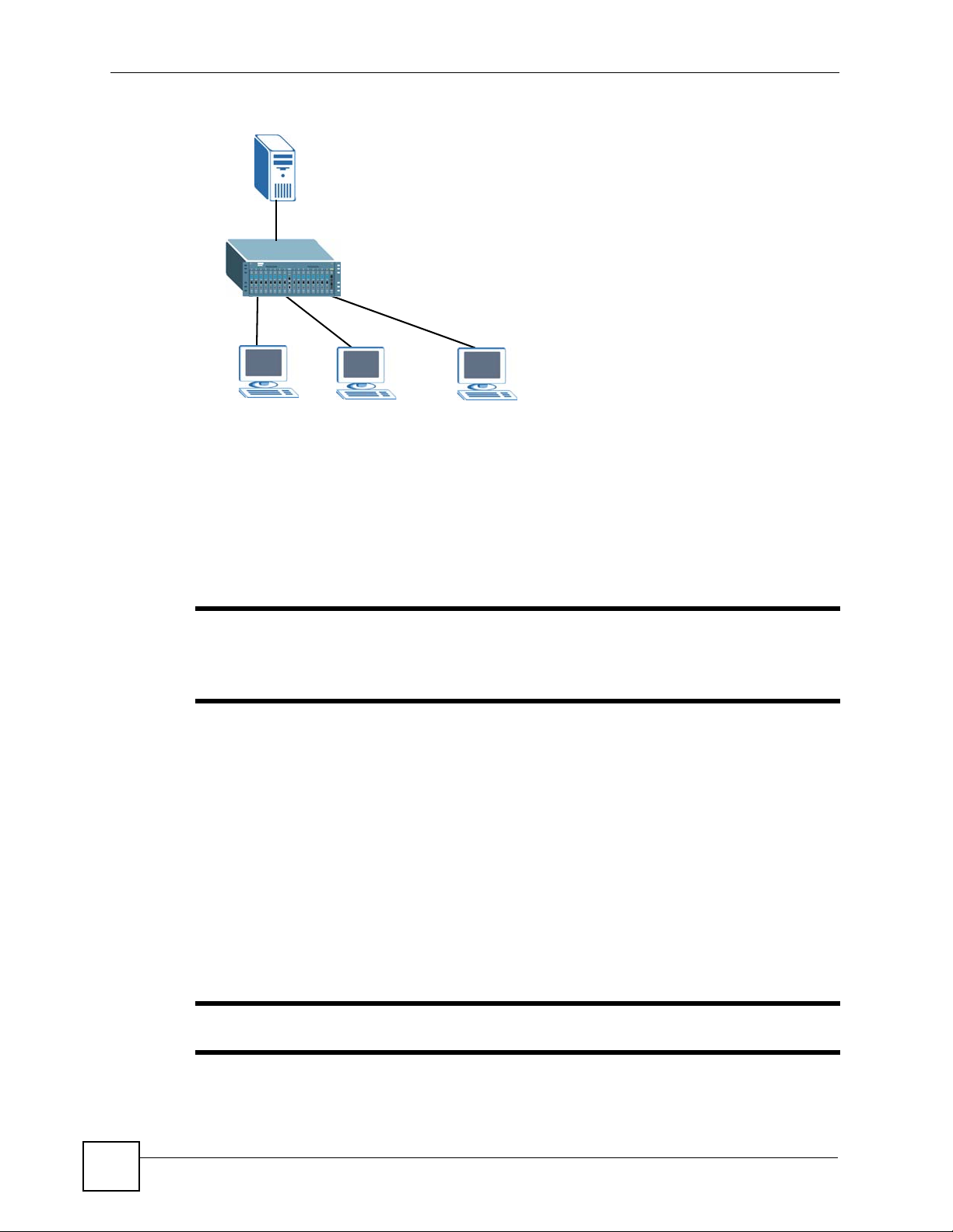
Chapter 6 Basic Setting
Figure 20 IGMP Proxy Network Example
A
12
The system will not respond to IGMP join and leave messages on the upstream interface. The
system only responds to IGMP query messages on the upstream interface. The system sends
IGMP query messages to the hosts that are members of the query VLAN.
The system only sends an IGMP leave messages via the upstream interface when the last host
leaves a multicast group.
The Ethernet port on the line card acts as the upstream interface. By default, the PON port is
set as a downstream interface.
3
" The OLT does not allow a PON port to send multicast traffic (except static
multicast traffic) to an uplink port. Only the uplink port can forward multicast
traffic to the PON port.
6.7 DBA (Dynamic Bandwidth Allocation)
In an EPON network, to prevent network congestion, dynamic bandwidth allocation allows
the OLT to quickly re-assign unused bandwidth based on traffic requirements. The OLT
periodically broadcasts discovery messages to all ONUs. The ONUs then can register and send
report messages to request bandwidth for data transmission. The OLT bases on the registered
ONU’s RTT (Round Trip Time) and bandwidth request to decide when and how long the ONU
can transmit data. Bandwidth re-assignment can be for an ONU or for the priority-level
queues. In addition to reassigning bandwidth on the go, DBA helps to ensure quality of service
on the network.
" A PON port allows only one ONU to transmit data at a time.
64
OMC-2301 User’s Guide
Page 65

By default, the OLT uses the Plato DBA algorithm that allows you to fully utilize bandwidth in
your network environment. With the Plato DBA algorithm, the OLT assigns bandwidth based
on report messages from ONUs, link priority and delay tolerance. In addition, the OLT
guarantees a minimum upstream bandwidth and provides the best-effort maximum upstream
bandwidth.
6.8 EPON Common Setup
Use the EPON Setup screen to configure general PON (or fiber) interface settings. Click
Basic Setting > EPON Common Setup.
Figure 21 EPON Setup
Chapter 6 Basic Setting
OMC-2301 User’s Guide
65
Page 66

Chapter 6 Basic Setting
The following table describes the labels in this screen.
Table 15 EPON Setup
LABEL DESCRIPTION
p2p Access Peer-to-peer (p2p) access allows ONUs on the same port to send packets to each
DBA Mode The OLT uses the Plato mode to assign bandwidth dynamically based on the priority
Aging Time This is how long all dynamically learned MAC addresses remain in the MAC address
Upstream/Downstream Priority Queue Assignment
IEEE 802.1p defines up to 8 separate traffic types by inserting a tag into a MAC-layer frame that
contains bits to define class of service. Frames without an explicit priority tag are given the default
priority of the ingress port. Use the following fields to configure the priority level-to-physical queue
mapping.
On the ONUs, traffic assigned to higher index queues gets serviced faster while traffic in lower index
queues may be dropped if the network is congested.
Priority Level (The following descriptions are based on the traffic types defined in the IEEE 802.1d
standard (which incorporates IEEE 802.1p).
Priority 7 Typically used for network control traffic such as router configuration messages.
Priority 6 Typically used for voice traffic that is especially sensitive to jitter (jitter is the variations
Priority 5 Typically used for video that consumes high bandwidth and is sensitive to jitter.
Priority 4 Typically used for controlled load, latency-sensitive traffic such as SNA (Systems
Priority 3 Typically used for “excellent effort” or better than best effort and would include
Priority 2 This is for “spare bandwidth”.
Priority 1 This is typically used for non-critical “background” traffic such as bulk transfers that
Priority 0 Typically used for best-effort traffic.
IGMP
Snooping
IGMP Proxy Select this option to enable IGMP proxy.
IGMP Last
Member
Upstream
Multicast
forwarding
other directly (without having to route through the uplink ports).
Select the port(s) you want to allow peer-to-peer communication.
Clear the check box to disable this feature. In this case, all packets from the ONUs on
the same port are sent to the uplink interface. ONUs cannot communicate with each
other.
and delay tolerance settings.
You can configure bandwidth settings in the EPON Profile screen.
table before they age out (and must be relearned).
Enter a time from 10 to 86400 seconds.
in delay).
Network Architecture) transactions.
important business traffic that can tolerate some delay.
are allowed but that should not affect other applications and users.
Select this option to enable IGMP snooping. This allows the OLT to passively learn
multicast group.
This allows the OLT to act as an IGMP proxy device to reduce multicast traffic. The
OLT issues IGMP host messages to a multicast router or server on behalf of the
connected multicast hosts.
Select this option to set the ONU to query all group members when a group leave
message is received. This is to confirm that all group members wish to leave that
IGMP group.
Clear this option to disable this feature. When a group leave message is received, all
group members are removed from an IGMP group without confirmation checks.
Select Pass to forward upstream packets with a matching multicast MAC address in
the range shown.
Select Discard to drop upstream packets with a matching multicast MAC address in
the range shown.
66
OMC-2301 User’s Guide
Page 67

Table 15 EPON Setup (continued)
LABEL DESCRIPTION
Downstream
Multicast
Forwarding
Apply Click Apply to save the settings.
Cancel Click Cancel to reset the fields to your previous configuration.
6.9 ONU Setup
Use the ONU Setup screen to associate profiles to an ONU. When the ONU has successfully
registered (or connected) to the OLT, settings in the associated profiles are set to the ONU.
Click Basic Setting > ONU Setup to display the configuration screen.
Figure 22 ONU Setup
Chapter 6 Basic Setting
Select Pass to forward downstream packets with a matching multicast MAC address
in the range shown.
Select Discard to drop downstream packets with a matching multicast MAC address
in the range shown.
The following table describes the labels in this screen.
Table 16 ONU Setup
LABEL DESCRIPTION
Active Select this option to activate this profile.
ONU Name Enter a descriptive name (up to 20 alpha-numerical characters) to identify the ONU to
Port Select the port to which the ONU is connected.
OMC-2301 User’s Guide
Clear this check box to disable the profile.
which this service is applied.
67
Page 68

Chapter 6 Basic Setting
Table 16 ONU Setup (continued)
LABEL DESCRIPTION
MAC Address Select the first radio button and manually enter the MAC address of the ONU to which
EPON Profile Select the EPON profile to apply to the ONU. You can configure EPON profiles in the
Classifier Filter
Profile
VLAN Profile Select the VLAN profile to apply to the ONU. You can configure VLAN profiles in the
Priority Profile Select the packet priority profile to apply to the ONU. Refer to Section 6.10 on page
4-Port ONU
Profile
Add Click Add to save the settings.
Cancel Click Cancel to reset the fields to your previous configuration.
Clear Click Clear to reset the fields to the default settings.
Port This field displays the port index number.
Active This field displays whether the service is enabled or not.
ONU Name This field displays the name of the ONU on this port. Click a name to configure the
MAC Address This field displays the MAC address of the ONU allowed to use the service on this
EPON Profile This field displays the name of the EPON profile the ONU on this port uses. Click a
Classifier Filter
Profile
VLAN Profile This field displays the name of the VLAN profile the ONU on this port uses. Click a
Priority Profile This field displays the name of the priority profile the ONU on this port uses. Click a
4-Port ONU
Profile
Delete Click Delete to remove the selected entry from the summary table.
this service is to be applied.
Alternatively, click the ONU name “Deafult” of a PON port in the table below. The
MAC address of the ONU connected to the selected PON port displays automatically
in the drop-down list box of the second radio button. Select the second radio button
and the MAC address of the ONU to which this service is to be applied. To create a
new service profile, you need to enter a new name in the ONU Name field.
EPON Profile screen (refer to Section 6.10 on page 69).
Select the packet classification filter profile to apply to the ONU. Refer to Section 7.2
on page 79 for more information on classification filter profile setup.
VLAN Profile screen (refer to Section 8.4 on page 86).
69 for more information on priority profile setup.
Select the 4-port ONU profile to apply to the 4-port ONU. Refer to Section 6.12 on
page 74 for more information on 4-port ONU profile setup.
ONU settings.
port. ff:ff:ff:ff:ff:ff:ff means that any ONU is allowed on the port.
name to configure the EPON profile.
This field displays the name of the classifier filter profile the ONU on this port uses.
Click a name to configure the classifier filter profile.
name to configure the VLAN profile.
name to configure the priority profile.
This field displays the name of the 4-port ONU profile the ONU on this port uses. Click
a name to configure the 4-port ONU profile.
68
Note: You cannot delete the default services.
Cancel Click Cancel to clear the Delete check boxes.
OMC-2301 User’s Guide
Page 69

6.10 EPON Profile
Use the EPON Profile screen to configure upstream/downstream bandwidth limit, priority
level, delay priority and the MAC address learning settings. Once you have set the profile
settings, you can apply it to the ONU in the ONU Setup screens (refer to Section 6.9 on page
67).
Your OMC comes with a “Default” profile contains the settings that work in most network
environment.
When you create a profile having the same name as an existing profile, the previous settings
will be replaced in the existing profile. Current field settings are displayed in bold text labels.
Click Basic Setting > EPON Profile to display the configuration screen.
Chapter 6 Basic Setting
OMC-2301 User’s Guide
69
Page 70
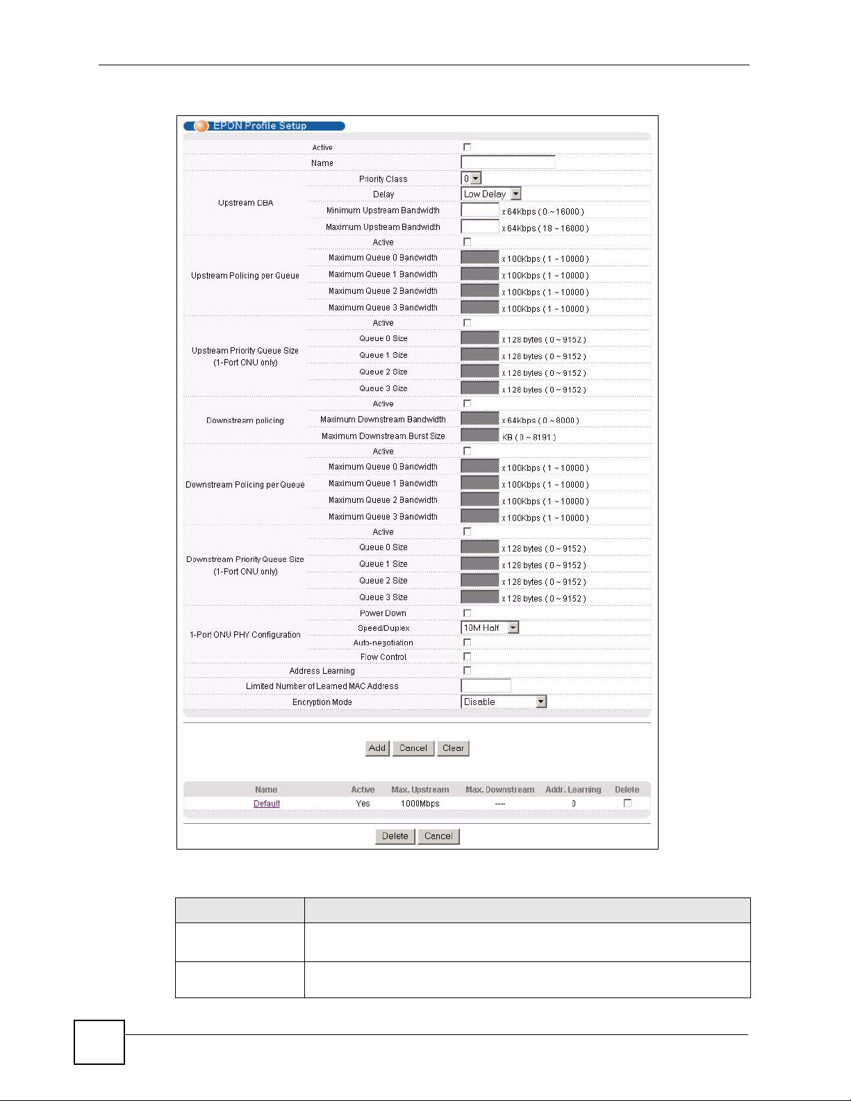
Chapter 6 Basic Setting
Figure 23 EPON Profile
70
The following table describes the labels in this screen.
Table 17 EPON Profile
LABEL DESCRIPTION
Active Select this option to activate this profile.
Clear this check box to disable the profile.
Name Enter a descriptive name (up to 20 alphanumerical characters) to identify this
profile.
OMC-2301 User’s Guide
Page 71

Chapter 6 Basic Setting
Table 17 EPON Profile (continued)
LABEL DESCRIPTION
Upstream DBA
Priority Class Select a traffic priority level for a logical link.
The higher the priority (larger number), the more likely that the ONU gets the
unused upstream bandwidth (up to the maximum bandwidth setting) after the
minimum bandwidth requirement is met.
Delay Specify the delay tolerance of a logical link for bandwidth allocation when
network congestion occurs.
Select Low Delay for the packets to get serviced faster. This is recommended
when you have real-time applications (such as VoIP) on the network.
Select High Delay to get less service time slots. Packets are serviced slower.
Minimum Upstream
Bandwidth
Maximum Upstream
Bandwidth
Upstream Policing per Queue
Active Select Active to apply the bandwidth limit to the upstream traffic on the queues
Maximum Queue 0
Bandwidth
Maximum Queue 1
Bandwidth
Maximum Queue 2
Bandwidth
Maximum Queue 3
Bandwidth
Upstream Priority Queue Size (1-Port ONU only)
Active Select Active to set the queue size for the upstream traffic.
Queue 0 Size Specify the size (in byte) for queue 0.
Queue 1 Size Specify the size (in byte) for queue 1.
Queue 2 Size Specify the size (in byte) for queue 2.
Queue 3 Size Specify the size (in byte) for queue 3.
Downstream Policing
Specify the minimum upstream bandwidth guaranteed to the ONU. Upstream
traffic refers to traffic from the ONU to the OLT.
The number you entered is multiplied by 64.
Specify the maximum upstream bandwidth guaranteed to the ONU. Upstream
traffic refers to traffic from the ONU to the OLT.
The number you entered is multiplied by 64.
then configure the settings in the field below. Upstream traffic refers to traffic
from the ONU to the OLT.
Specify the maximum upstream bandwidth for packets in queue 0.
The number you entered is multiplied by 100.
Specify the maximum upstream bandwidth for packets in queue 1.
The number you entered is multiplied by 100.
Specify the maximum upstream bandwidth for packets in queue 2.
The number you entered is multiplied by 100.
Specify the maximum upstream bandwidth for packets in queue 3.
The number you entered is multiplied by 100.
The number you entered is multiplied by 128.
The number you entered is multiplied by 128.
The number you entered is multiplied by 128.
The number you entered is multiplied by 128.
Note: Downstream Policing applies the bandwidth limit to the downstream traffic
equally and drops all packets when the maximum bandwidth is reached even
though the packets have different priorities. If the downstream traffic flows are
assigned different priorities, use Downstream Policing per Queue to make
sure packets with a higher priority can be processed first.
Active Select Active to control the downstream traffic (from the OLT to the ONU).
OMC-2301 User’s Guide
71
Page 72

Chapter 6 Basic Setting
Table 17 EPON Profile (continued)
LABEL DESCRIPTION
Maximum
Downstream
Bandwidth
Maximum
Downstream Burst
Size
Downstream Policing per Queue
Active Select Active to apply the bandwidth limit to the upstream traffic on the queues
Maximum Queue 0
Bandwidth
Maximum Queue 1
Bandwidth
Maximum Queue 2
Bandwidth
Maximum Queue 3
Bandwidth
Downstream Priority Queue Size (1-Port ONU only)
Active Select Active to set the queue size for the downstream traffic.
Queue 0 Size Specify the size (in byte) for queue 0.
Queue 1 Size Specify the size (in byte) for queue 1.
Queue 2 Size Specify the size (in byte) for queue 2.
Queue 3 Size Specify the size (in byte) for queue 3.
1-Port ONU PHY Configuration
Power Down Select this option to disable the connection to the ONU.
Speed/Duplex Select the link speed and duplex mode (10M/Half, 10M/Full, 100M/Half, 100M/
Auto-negotiation Select this option to establish the connection to the ONU using auto-negotiation
Flow Control IEEE802.3x flow control is used in full duplex mode to send a pause signal to
Address Learning MAC address learning reduces outgoing broadcast traffic. For MAC address
This field is applicable when you select Downstream Policing. Downstream
traffic refers to traffic from the OLT to the ONU.
Specify the maximum downstream bandwidth allowed for the ONU.
The number you entered is multiplied by 64.
This field is applicable when you select Downstream Policing. Downstream
traffic refers to traffic from the OLT to the ONU.
Specify the maximum downstream burst size that an ONU is allowed to send
for a single traffic burst. This assigns more bandwidth to the ONU for a short
burst period without changing the profile settings.
then configure the settings in the field below. Downstream traffic refers to traffic
from the OLT to the ONU.
Specify the maximum downstream bandwidth for packets in queue 0.
The number you entered is multiplied by 100.
Specify the maximum downstream bandwidth for packets in queue 1.
The number you entered is multiplied by 100.
Specify the maximum downstream bandwidth for packets in queue 2.
The number you entered is multiplied by 100.
Specify the maximum downstream bandwidth for packets in queue 3.
The number you entered is multiplied by 100.
The number you entered is multiplied by 128.
The number you entered is multiplied by 128.
The number you entered is multiplied by 128.
The number you entered is multiplied by 128.
Full or 1000M/Full) for the connection to the ONU.
for the link speed and duplex mode.
the sending port, causing it to temporarily stop sending signals when the
receiving port memory buffers fill.
Select this option to enable flow control for the connection to the ONU.
learning to occur on a port, the port itself must be active with address learning
enabled.
72
OMC-2301 User’s Guide
Page 73

Chapter 6 Basic Setting
Table 17 EPON Profile (continued)
LABEL DESCRIPTION
Limited Number of
Learned MAC
Addresses
Encryption Mode You can set the OLT to encrypt data using AES128 to provide secure
Add Click Apply to save the settings.
Cancel Click Cancel to reset the fields to your previous configuration.
Clear Click Clear to reset the fields to the default settings.
Name This field displays the descriptive name of a profile.
Active This field displays whether the priority profile is active or not.
Max. Upstream This field displays the maximum upstream bandwidth.
Max. Downstream This field displays the maximum amount of downstream bandwidth.
Addr. Learning This field displays the maximum number of MAC addresses is allowed.
Delete Click Delete to remove the selected entry from the summary table.
Cancel Click Cancel to clear the Delete check boxes.
Use this field to limit the number of (dynamic) source MAC addresses that may
be learned on the ONU.
For example, if you set this field to "8", then only the devices with these eight
learned MAC addresses may access through the ONU at any one time. A ninth
device would have to wait until one of the eight learned MAC addresses aged
out. MAC address aging time can be set in the EPON Setup screen.
Select the number of MAC address an ONU can learn.
communication through the ONUs.
Specify the direction of the traffic to which the OLT encrypts. Data encryption
may affect transmission performance.
Select Disabled if you do not want to encrypt data.
6.11 Introduction to VLANs
A VLAN (Virtual Local Area Network) allows a physical network to be partitioned into
multiple logical networks. Devices on a logical network belong to one group. A device can
belong to more than one group. With VLAN, a device cannot directly talk to or hear from
devices that are not in the same group(s); the traffic must first go through a router.
In MTU (Multi-Tenant Unit) applications, VLAN is vital in providing isolation and security
among the subscribers. When properly configured, VLAN prevents one subscriber from
accessing the network resources of another on the same LAN, thus a user will not see the
printers and hard disks of another user in the same building.
VLAN also increases network performance by limiting broadcasts to a smaller and more
manageable logical broadcast domain. In traditional switched environments, all broadcast
packets go to each and every individual port. With VLAN, all broadcasts are confined to a
specific broadcast domain.
" VLAN is unidirectional; it only governs outgoing traffic.
See Chapter 8 on page 83 for information on IEEE 802.1Q tagged VLANs.
OMC-2301 User’s Guide
73
Page 74

Chapter 6 Basic Setting
6.11.1 Port-based VLANs
Port-based VLANs are VLANs where the packet forwarding decision is based on the
destination MAC address and its associated port.
Port-based VLANs require allowed outgoing ports to be defined for each port. Therefore, if
you wish to allow two subscriber ports to talk to each other, for example, between conference
rooms in a hotel, you must define the egress (an egress port is an outgoing port, that is, a port
through which a data packet leaves) for both ports.
Port-based VLANs are specific only to the device on which they were created.
6.12 4-Port ONU Profile
Use the 4-Port ONU Profile screen to create or edit a profile that contains connection and
port-based VLAN settings for a 4-port ONU. Once you have set the profile settings, you can
apply it to the ONU in the ONU Setup screens (refer to Section 6.9 on page 67).
Your OMC comes with a “Default” profile containing settings that work in most network
environment.
When you create a profile having the same name as an existing profile, the previous settings
will be replaced in the existing profile.
Click Basic Setting > 4-Port ONU Profile to display the configuration screen.
74
OMC-2301 User’s Guide
Page 75

Figure 24 4-Port ONU Profile
Chapter 6 Basic Setting
The following table describes the labels in this screen.
Table 18 4-Port ONU Profile
LABEL DESCRIPTION
Active Select this option to activate this profile.
Name Enter a descriptive name (up to 20 alphanumerical characters) to identify this
Port-based VLAN Select whether to activate port-based VLAN on the ONU.
ONU PHY This field displays the number of the port on the ONU.
Power Down Select this option to disable the connection to the ONU.
Auto-negotiation Select this option to establish the connection to the ONU using auto-negotiation
OMC-2301 User’s Guide
Clear this check box to disable the profile.
profile.
for the link speed and duplex mode.
75
Page 76

Chapter 6 Basic Setting
Table 18 4-Port ONU Profile (continued)
LABEL DESCRIPTION
Speed Select the link speed (10 or 100) in Mbps for the connection to the ONU.
Duplex Select the duplex mode (half or full) for the connection to the ONU.
Flow Control IEEE 802.3x flow control is used in full duplex mode to send a pause signal to
Port-based VLAN This field displays the number of the port on the ONU.
PVID Enter the port’s VLAN ID (between 1 and 4094). A VLAN tag reflecting the
Forwarding Table Select the outgoing port(s) (in the Forwarding Table) through which traffic
Upstream Priority Queue Size
Active Select Active to set the queue size for the upstream traffic.
Queue 0 Size Specify the size (in byte) for queue 0.
Queue 1 Size Specify the size (in byte) for queue 1.
Queue 2 Size Specify the size (in byte) for queue 2.
Queue 3 Size Specify the size (in byte) for queue 3.
Downstream Priority Queue Size
Active Select Active to set the queue size for the downstream traffic.
Queue 0 Size Specify the size (in byte) for queue 0.
Queue 1 Size Specify the size (in byte) for queue 1.
Queue 2 Size Specify the size (in byte) for queue 2.
Queue 3 Size Specify the size (in byte) for queue 3.
Add Click Apply to save the settings.
Cancel Click Cancel to reset the fields to your previous configuration.
Clear Click Clear to reset the fields to the default settings.
Name This field displays the descriptive name of a profile.
Active This field displays whether the profile is active or not.
Delete Click Delete to remove the selected entry from the summary table.
Cancel Click Cancel to clear the Delete check boxes.
the sending port, causing it to temporarily stop sending signals when the
receiving port memory buffers fill.
Select this option to enable flow control for the connection to the ONU.
PVID is inserted in the frame forwarded through the port.
Note: The ports must be in the same VLAN group to
communicate with each other.
from the port (in the Port-based VLAN field) is allowed to go.
To allow two ports to talk to each other, you must define the outgoing port for
both ports.
The number you entered is multiplied by 128.
The number you entered is multiplied by 128.
The number you entered is multiplied by 128.
The number you entered is multiplied by 128.
The number you entered is multiplied by 128.
The number you entered is multiplied by 128.
The number you entered is multiplied by 128.
The number you entered is multiplied by 128.
76
OMC-2301 User’s Guide
Page 77

PART III
Advanced
Classifier Filter Profile (79)
VLAN Profile (83)
Priority Profile (93)
Static MAC Forward Setup (97)
Destination Filter (101)
Port Authentication (105)
Access Control (109)
77
Page 78

78
Page 79

CHAPTER 7
Classifier Filter Profile
This chapter shows you how to configure the Classifier Filter Profile screen to filter packets.
7.1 Overview
In addition to filtering packets based on the MAC address (refer to Section 11.3 on page 102),
you can configure the ONU to forward or drop packets based on the VLAN ID, protocol
number, Ethernet type, source or destination IP address or the TCP/UDP source port number.
7.2 Classifier Filter Profile Setup
Use the Classifier Filter Profile screen to configure actions on the grouped traffic flow.
Your OMC comes with two pre-defined classification filter profiles. The “Default” filter
profile forwards all packets (tagged or untagged). As the name implies, the “Stop_traffic”
filter profile discards all packets, thus preventing the subscriber from sending traffic through
the ONU.
Click Advanced Application > Classifier Filter Profile to display the configuration screen.
Figure 25 Classifier Filter Profile Setup
OMC-2301 User’s Guide
79
Page 80

Chapter 7 Classifier Filter Profile
The following table describes the labels in this screen.
Table 19 Classifier Filter Profile Setup
LABEL DESCRIPTION
Active Select this option to enable this profile.
Name Enter a descriptive name (up to 20 alphanumerical characters) to identify this profile.
Upstream
Default VLAN
Filter
Untagged
Frames
Tagged
Frames
Downstream
Default VLAN
Filter
Untagged
Frames
Tagged
Frames
Upstream/
Downstream
Filter Rules
Index This field displays the index number.
Active Select this option to enable the packet prioritization setting.
Direction Select the direction of the traffic to which the setting is applied.
Specify how the ONU is to treat outgoing tagged/untagged packets to the OMC.
Select Discard to drop outgoing packets without a VLAN tag.
Select Pass to send outgoing packets without a VLAN tag.
Select Discard to drop outgoing VLAN-tagged packets.
Select Pass to forward outgoing VLAN-tagged packets.
Specify how the ONU is to treat incoming tagged/untagged packets from the OMC.
Select Discard to drop incoming packets without a VLAN tag.
Select Pass to forward incoming packets without a VLAN tag.
Select Discard to drop incoming VLAN-tagged packets.
Select Pass to forward incoming VLAN-tagged packets.
Set the fields to configure upstream/downstream VLAN filer rules.
Or select a filter type from the list.
80
OMC-2301 User’s Guide
Page 81

Chapter 7 Classifier Filter Profile
Table 19 Classifier Filter Profile Setup (continued)
LABEL DESCRIPTION
Value Enter the packet type value to check.
For VLAN filter rules, enter a VID (1-4094).
If you select Ethertype in the Filter Rules field, enter the Ethernet type number in
hexadecimal value (0x0000 - 0xff0f). The 0x prefix is already entered for you. Refer to
Table 25 on page 95 for common Ethernet type numbers.
If you select IPv4 Protocol in the Filter Rules field, enter an IPv4 protocol number (1-
255). Refer to Table 26 on page 96 for common protocol numbers.
If you select Src TCP Port or Src UDP Port in the Filter Rules field, enter a TCP
service port number (1 - 65535).
If you select Src IP Address in the Filter Rules field, enter a source IP address in
dotted decimal notation. For example, 192.168.1.10.
If you select Dest IP Address in the Filter Rules field, enter a destination IP address
in dotted decimal notation. For example, 192.168.1.10.
Action Select whether to drop (Discard) or forward (Pass) the classified packets.
Add After you set the fields above, click Add to insert a new rule.
Cancel Click Cancel to reset the fields.
Clear Click Clear to begin configuring this screen afresh.
Name This field displays the name of a profile. Click a name to configure the profile.
Active This field displays whether the profile is enabled or not.
Delete Select the entry(ies) that you want to remove in the Delete column and then click the
Delete button.
Cancel Click Cancel to clear the Delete check boxes.
7.2.1 Example: Classifier Filter Profile
The following example sets the ONU to forwards all untagged packets and drops all tagged
packets from the OLT. The ONU drops outgoing packets with VLAN ID 10 to the OLT.
Figure 26 Classifier Filter Profile: Example
OMC-2301 User’s Guide
81
Page 82

Chapter 7 Classifier Filter Profile
82
OMC-2301 User’s Guide
Page 83

CHAPTER 8
VLAN Profile
This chapter describes how to configure VLAN profiles for the ONUs to manage VLAN
traffic.
8.1 Introduction to IEEE 802.1Q Tagged VLANs
A tagged VLAN uses an explicit tag (VLAN ID) in the MAC header to identify the VLAN
membership of a frame across bridges - they are not confined to the device on which they were
created. The VLANs can be created statically by hand or dynamically through GVRP. The
VLAN ID associates a frame with a specific VLAN and provides the information that devices
need to process the frame across the network. A tagged frame is four bytes longer than an
untagged frame and contains two bytes of TPID (Tag Protocol Identifier, residing within the
type/length field of the Ethernet frame) and two bytes of TCI (Tag Control Information, starts
after the source address field of the Ethernet frame).
The CFI (Canonical Format Indicator) is a single-bit flag, always set to zero for Ethernet
switching devices. If a frame received at an Ethernet port has a CFI set to 1, then that frame
should not be forwarded as it is to an untagged port. The remaining twelve bits define the
VLAN ID, giving a possible maximum number of 4,096 VLANs. Note that user priority and
VLAN ID are independent of each other. A frame with VID (VLAN Identifier) of null (0) is
called a priority frame, meaning that only the priority level is significant and the default VID
of the ingress port is given as the VID of the frame. Of the 4096 possible VIDs, a VID of 0 is
used to identify priority frames and value 4095 (FFF) is reserved, so the maximum possible
VLAN configurations are 4,094.
TPID
2 Bytes
User Priority
3 Bits
CFI
1 Bit
VLAN ID
12 bits
8.1.1 Forwarding Tagged and Untagged Frames
VLAN group ID (or VID) is a unique number than identifies a VLAN. A port VID (PVID) is
the VID associated to a physical port. A PVID defines the VLAN group to which a port
belongs.
The ONU is capable of passing tagged or untagged frames. To forward a frame from an
802.1Q VLAN-aware device to an 802.1Q VLAN-unaware device, the ONU first decides
where to forward the frame and it may then strip off the VLAN tag or add a new VLAN tag.
To forward a frame from an 802.1Q VLAN-unaware device to an 802.1Q VLAN-aware
device, the ONU first decides where to forward the frame, and then inserts a VLAN tag
reflecting the ingress port's default VID.
OMC-2301 User’s Guide
83
Page 84

Chapter 8 VLAN Profile
The egress (outgoing) port(s) of a frame is determined on the combination of the destination
MAC address and the VID of the frame. For a unicast frame, the egress port (based on the
destination MAC address) must be a member of the VID, also; otherwise, the frame is
blocked. A broadcast frame (or a multicast frame for a multicast group that is known by the
system) is duplicated only on ports that are members of the VID (except the ingress port
itself), thus confining the broadcast to a specific domain.
Whether to tag an outgoing frame depends on the setting of the egress port on an individual
VLAN and port basis (remember that a port can belong to multiple VLANs). If the tagging on
the egress port is enabled for the VID of a frame, then the frame is transmitted as a tagged
frame; otherwise, it is transmitted as an untagged frame.
8.2 VLAN Stacking
A service provider can use VLAN stacking to allow it to distinguish multiple customers
VLANs, even those with the same (customer-assigned) VLAN ID, within its network.
Use VLAN stacking to add an outer VLAN tag to the inner IEEE 802.1Q tagged frames that
enter the network. By tagging the tagged frames (“double-tagged” frames), the service
provider can manage up to 4,094 VLAN groups with each group containing up to 4,094
customer VLANs. This allows a service provider to provide different service, based on
specific VLANs, for many different customers.
A service provider’s customers may require a range of VLANs to handle multiple
applications. A service provider’s customers can assign their own inner VLAN tags on ports
for these applications. The service provider can assign an outer VLAN tag for each customer.
Therefore, there is no VLAN tag overlap among customers, so traffic from different customers
is kept separate.
8.2.1 VLAN Stacking Example
In the following example figure, both A and B are Service Provider’s Network (SPN)
customers with VPN tunnels between their head offices and branch offices respectively. Both
have an identical VLAN tag for their VLAN group. The service provider can separate these
two VLANs within its network by adding tag 37 to distinguish customer A and tag 48 to
distinguish customer B at edge device 1 and then stripping those tags at edge device 2 as the
data frames leave the network.
84
OMC-2301 User’s Guide
Page 85

Figure 27 VLAN Stacking Example
8.3 VLAN Tag Format
Chapter 8 VLAN Profile
A VLAN tag (service provider VLAN stacking or customer IEEE 802.1Q) consists of the
following three fields.
Table 20 VLAN Tag Format
Type Priority VID
Type is a standard Ethernet type code identifying the frame and indicates that whether the
frame carries IEEE 802.1Q tag information. SP TPID (Service Provider Tag Protocol
Identifier) is the service provider VLAN stacking tag type. Many vendors use 0x8100 or
0x9100.
Priority refers to the IEEE 802.1p standard that allows service providers to prioritize traffic
based on the class of service (CoS) the customer has paid for.
• On the OMC, configure priority level on inner IEEE 802.1Q in the VLAN Profile screen.
• "0" is the lowest priority level and "7" is the highest.
VID is the VLAN ID. SP VID is the VID for the second (service provider’s) VLAN tag.
8.3.1 Frame Format
The frame format for an untagged Ethernet frame, a single-tagged 802.1Q frame (customer)
and a “double-tagged” 802.1Q frame (service provider) is shown next.
Table 21 Single and Double Tagged 802.11Q Frame Format
DA SA SPTPID Priority VID TPID Priority VID Len/
DA SA Len/
Etype
DA SA TPID Priority VID Len/
Etype
Etype
Data FCS Untagged
Ethernet frame
Data FCS
Data FCS
IEEE 802.1Q
customer
tagged frame
Double-tagged
frame
OMC-2301 User’s Guide
85
Page 86

Chapter 8 VLAN Profile
Table 22 802.1Q Frame
DA Destination Address Priority 802.1p Priority
SA Source Address Len/Etype Length and type of Ethernet frame
(SP)TPID (Service Provider) Tag Protocol
IDentifier
VID VLAN ID FCS Frame Check Sequence
8.4 Configuring a VLAN Profile
Use the VLAN Profile screen to configure VLAN settings to apply to the connected ONU(s)
(in the ONU Setup screen). A VLAN profile allows the ONU(s) to perform the following
actions on the incoming packets:
• Replace VID
• Add or remove an outer VLAN tag
•Set priority
No action is done on the OLT which forwards the packets to the destination through the uplink
Gigabit Ethernet ports.
Data Frame data
Click Advanced Applications > VLAN Profile in the navigation panel to display the screen
as shown.
86
OMC-2301 User’s Guide
Page 87
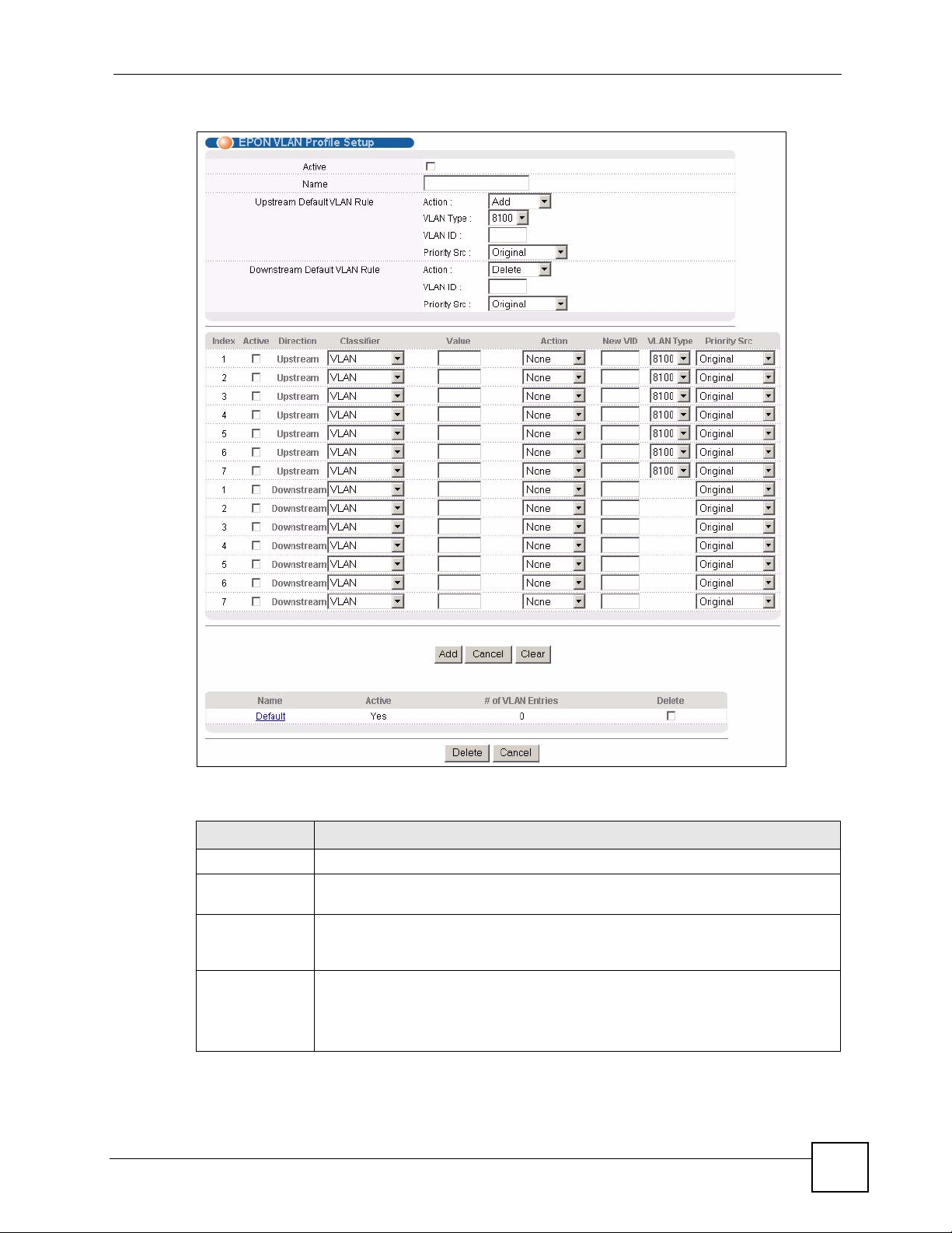
Figure 28 EPON VLAN Profile Setup
Chapter 8 VLAN Profile
The following table describes the labels in this screen.
Table 23 EPON VLAN Profile Setup
LABEL DESCRIPTION
Active Select this open to enable this VLAN profile.
Name Enter a descriptive name (up to 20 alpha-numerical characters with spaces
Upstream
Default VLAN
Rule
Action Specify the action to perform on the packets.
OMC-2301 User’s Guide
allowed) to identify this VLAN profile.
Configure the default settings for outgoing traffic (from the ONU to the OLT) that
does not match any VLAN rule below.
Select Add to insert a VLAN tag to the outgoing packets.
Select Exchange to replace the VID with the one specified in the VLAN ID field.
Select None to forward packets without any changes.
87
Page 88

Chapter 8 VLAN Profile
Table 23 EPON VLAN Profile Setup (continued)
LABEL DESCRIPTION
VLAN Type This field is applicable when you select Add or Exchange in the Action field.
VLAN ID Enter a VLAN ID (from 1 to 4094) of the packet.
Priority Src Select Original if you don’t want to change the priority of the packets.
Downstream
Default VLAN
Rule
Action Specify the action to perform on the packets.
VLAN ID Enter the VLAN ID (from 1 to 4094).
Priority Src Select Original if you don’t want to change the priority of the packets.
Index This field displays the index number for the VLAN rule.
Active Select this option to enable the VLAN rule.
Direction This field displays the direction of the traffic to which the rule applies.
Classifier Specify the packet type to check. Choices are Ethertype, IPv4 Protocol and
Value Enter the packet type value to check.
Select a standard Ethernet type code identifying the frame and indicates whether
the frame carries IEEE 802.1Q or IEEE802.1ad tag information.
For untagged frames, the system sets the VLAN type to 8100 regardless of your
setting here.
For tagged frames, the system sets the VLAN type (8100, 88A8 or 9100) that you
specify.
If you select Exchange in the Action field, this replaces the packet’s VLAN ID.
Select Priority Profile to change the packet priority based on the settings in the
priority profile configured for the ONU in the ONU Setup screen. If no priority
settings are configured for the matched packets, the TOS-COS settings in the
Priority Profile screen apply.
Configure the default settings for the incoming traffic (from the OLT to the ONU) that
does not match any VLAN rule.
Select Delete to delete a VLAN tag from the incoming packets.
Select Exchange to replace the VID with the one specified in the VLAN ID field.
Select None to send the packets without any changes.
If you select Delete, the ONU deletes the outer VLAN tag (that matches this VLAN
ID) from incoming packets.
If you select Exchange in the Action field, this replaces the packet’s VLAN ID.
Select Priority Profile to change the packet priority based on the settings in the
priority profile configured for the ONU in the ONU Setup screen. If no priority
settings are configured for the matched packets, the TOS-COS settings in the
Priority Profile screen apply.
Upstream means traffic from the ONU to the OLT while downstream traffic goes
from the OLT to the ONU.
VLAN.
Select Ethertype to check the Ethernet type of the packet.
Select IPv4 Protocol to check the IPv4 protocol number of the packet.
Select VLAN to check the VLAN ID of the packet.
If you select Ethertype in the Classifier field, enter the Ethernet type number in
hexadecimal value (0x0000 - 0xff0f). The 0x prefix is already entered for you. Refer
to Table 25 on page 95 for common Ethernet type numbers.
If you select IPv4 Protocol in the Classifier field, enter an IPv4 protocol number (1-
255). Refer to Table 26 on page 96 for common protocol numbers.
If you select VLAN in the Classifier field, enter a VID (1-4094).
88
OMC-2301 User’s Guide
Page 89

Chapter 8 VLAN Profile
Table 23 EPON VLAN Profile Setup (continued)
LABEL DESCRIPTION
Action Specify the action to perform on the packets.
Select Add to insert a new VLAN tag to the outgoing packets.
Select Delete to delete a VLAN tag from the incoming packets.
Select Exchange to replace the VID with the one specified in the VLAN ID field.
Select None to send the packets without any changes.
New VID If you select Add or Exchange in the Action field, enter the VLAN ID you want the
ONU to insert or replace.
VLAN Type This field is applicable for upstream traffic and when you select Add or Exchange
in the Action field.
Select a standard Ethernet type code identifying the frame and indicates whether
the frame carries IEEE 802.1Q or IEEE802.1ad tag information.
For untagged frames, the system sets the VLAN type to 8100 regardless of your
setting here.
For tagged frames, the system sets the VLAN type (8100, 88A8 or 9100) that you
specify.
Priority Src Select Original if you don’t want to change the priority of the packets.
Select Priority Profile to change the packet priority based on the settings in the
priority profile configured for the ONU in the ONU Setup screen. If no priority
settings are configured for the matched packets, the TOS-COS settings in the
Priority Profile screen apply.
Add After you set the fields above, click Add to insert a new profile or save the settings
to an existing profile.
Cancel Click Cancel to reset the fields.
Clear Click Clear to begin configuring this screen afresh.
Name This field displays the descriptive name of a VLAN profile.
Active This field displays whether the VLAN profile is enabled or not.
# of VLAN
Entries
Delete Select the entry(ies) that you want to remove in the Delete column and then click
Cancel Click Cancel to clear the Delete check boxes.
This field displays the number of active VLAN rules for this profile.
the Delete button.
8.4.1 VLAN Profile: Example
In the following network example, you want to set the ONUs to check VLAN tagged packets
to the OLT. If a packet has a VLAN ID of 100, the ONU adds a second tag with VID 200
before transmitting.
OMC-2301 User’s Guide
89
Page 90

Chapter 8 VLAN Profile
Figure 29 VLAN Network Example 1
100
100
200
100
200
The following figure shows the VLAN profile setting on the OLT.
Figure 30 VLAN Profile: Example 1
In the ONU Setup screen, apply the configured VLAN profile to the ONU.
8.4.2 VLAN Profile: Example 2
In the following example, you want to set the ONU to check VLAN tagged packets from the
OLT. If a packet has a VLAN ID of 200, the ONU removes the outer VLAN tag before
sending the packet to the computers. The ONU discards all untagged packets.
Figure 31 VLAN Network Example 2
100
90
100
200
200
100
OMC-2301 User’s Guide
Page 91

Chapter 8 VLAN Profile
The following figure shows settings in the VLAN Profile screen to remove the VLAN tags
from the incoming packets.
Figure 32 VLAN Profile: Example 2
In the Classifier Filter Profile screen, set the Downstream Default VLAN Filter to discard
all untagged packets on the ONU.
Figure 33 VLAN Profile: Example 2: Classifier Filter Profile
In the ONU Setup screen, apply the configured classifier filter profile and VLAN profile to
the ONU.
OMC-2301 User’s Guide
91
Page 92

Chapter 8 VLAN Profile
92
OMC-2301 User’s Guide
Page 93

CHAPTER 9
Priority Profile
This chapter describes how you can change packet priorities using the Priority Profile screen.
9.1 Priority Profile Overview
Quality of Service (QoS) refers to both a network’s ability to deliver data with minimum delay,
and the networking methods used to control the use of bandwidth. Without QoS, all traffic data
is equally likely to be dropped when the network is congested. This can cause a reduction in
network performance and make the network inadequate for time-critical application such as
video-on-demand.
To ensure QoS on packets between layer 2 (L2) and layer 3 (L3) networks, you can configure
a priority profile to map TOS (L3) precedence bits to the COS (L2) value. Each COS value is
then mapped to the physical queue you specify in the EPON Common Setup screen. The
The OMC determines the COS value of a packet using one of the following methods:
• Using the IEEE 802.1p priority level in the VLAN tag.
• Using the port’s default priority setting.
• Mapping the TOS bits.
In addition to configuring TOS-COS mappings, you can do the following to ensure QoS on the
network using a priority profile:
• Group traffic based on the Ethernet type, VLAN group or protocol number. Then assign a
VLAN priority and queue to the classified traffic.
• Associate a priority profile to a service profile.
9.2 Configuring a Priority Profile
Click Advanced Application > Priority Profile to display the configuration screen. Use this
screen to change the precedence bits (TOS-COS mappings) and VLAN priority and assign
specified packets to queues. Once you have configured a priority profile, associate it to a
service profile to apply to an ONU.
OMC-2301 User’s Guide
93
Page 94

Chapter 9 Priority Profile
Figure 34 Priority Profile
94
The following table describes the labels in this screen.
Table 24 Priority Profile
LABEL DESCRIPTION
Active Select this option to enable this profile.
Name Enter a descriptive name (up to 20 alphanumerical characters) to identify this profile.
TOS-COS
Conversion
TOS 7 - 0 Select a COS level for the corresponding TOS number. The ONU adds the COS
Index This field displays the index number.
TOS-COS mapping on the ONU ensures that quality of service is maintained as
packets go through the network.
number to the packets.
Use the EPON Common Setup screen to map the COS levels to the queues.
OMC-2301 User’s Guide
Page 95

Chapter 9 Priority Profile
Table 24 Priority Profile (continued)
LABEL DESCRIPTION
Active Select this option to enable the packet prioritization setting.
Direction Select the direction of the traffic to which the setting apply.
Classifier Specify the type of packets to group into a traffic flow.
Use Ethertype to group packets based on the Ethernet type specified in the Value
field.
Select Source IP Address to group packets based on the source IP address
specified in the IP Address field.
Select Destination IP Address to group packets based on the destination IP address
specified in the IP Address field.
Value Enter the Ethernet type number in hexadecimal value (0x0000 - 0xff0f). The 0x prefix
is already entered for you. Refer to Table 25 on page 95 for common Ethernet type
numbers.
VLAN Priority You can set the ONU to add VLAN priority settings in the VLAN header of the packet.
This ensures quality of service between multiple switching/routing devices on the
network and allows flexible prioritization.
Enter a number between 0 and 7. The bigger the number, the higher the priority.
IP Address This field is applicable if you select either Source IP Address or Destination IP
Address in the Classifier field.
Enter the source or destination IP address in dotted decimal notation. For example,
172.23.37.205.
Queue Select the queue number (0-3) to which the classified packets are sent.
Add After you set the fields above, click Add to insert a new profile or save the settings to
an existing profile.
Cancel Click Cancel to reset the fields.
Clear Click Clear to begin configuring this screen afresh.
Name This field displays the name of a profile. Click on a name to configure the profile.
Active This field displays whether the profile is enabled or not.
TOS-COS
Conversion
Delete Select the entry(ies) that you want to remove in the Delete column and then click the
Cancel Click Cancel to clear the Delete check boxes.
This field displays the TOC-to-COS mappings.
Delete button.
The following table shows some common Ethernet types and the corresponding hexadecimal
number.
Table 25 Common Ethernet Types Numbers
ETHERNET TYPE NUMBER
IP ETHII 0800
X.75 Internet 0801
NBS Internet 0802
ECMA Internet 0803
Chaosnet 0804
X.25 Level 3 0805
XNS Compat 0807
Banyan Systems 0BAD
OMC-2301 User’s Guide
95
Page 96

Chapter 9 Priority Profile
Table 25 Common Ethernet Types Numbers (continued)
ETHERNET TYPE NUMBER
BBN Simnet 5208
IBM SNA 80D5
AppleTalk AARP 80F3
Some of the most common protocol names and port numbers are:
Table 26 Common Protocol Names and Numbers
PROTOCOL NAME NUMBER
ICMP 1
IGMP 2
TCP 6
UDP 17
IPv6 over IPv4 41
9.2.1 Example: Priority Profile
In this example, the OLT sets the VLAN priority to 7 (highest priority) on AppleTalk packets
that belong to a VLAN group. The AppleTalk packets are sent out through queue 3. Thus
AppleTalk packets in a VLAN group have the highest priority and get sent first. The following
figure shows the example configuration.
Figure 35 Priority Profile: Example
96
OMC-2301 User’s Guide
Page 97

CHAPTER 10
Static MAC Forward Setup
Use these screens to configure static MAC address forwarding.
10.1 Overview
A static MAC address is an address that has been manually entered in the MAC address table.
Static MAC addresses do not age out. When you set up static MAC address rules, you are
setting static MAC addresses for a port. This may reduce the need for broadcasting.
10.2 Static MAC Forwarding Status
You can view the number of static MAC forwarding rules you configure per Ethernet port in
the Static MAC Forwarding Status screen. Click Advanced Application > Static MAC
Forwarding.
Figure 36 Static MAC Forwarding Status
The following table describes the labels in this screen.
Table 27 Static MAC Forwarding Status
LABEL DESCRIPTION
Port No This field displays the port index number.
OMC-2301 User’s Guide
97
Page 98

Chapter 10 Static MAC Forward Setup
Table 27 Static MAC Forwarding Status (continued)
LABEL DESCRIPTION
Number of
Static MA C
Static MAC
Forwarding
This field displays the number of static MAC forwarding rules you have configured for
this port.
Click the link to display a screen where you can configure a static MAC forwarding
rule.
10.3 Configuring Static MAC Forwarding
Click Advanced Applications > Static MAC Forwarding and click a Static MAC
Forwarding link to display a configuration screen. Use this screen to set the OLT to forward
packets with the specified MAC address to the selected ONU.
Figure 37 Static MAC Forwarding
The following table describes the labels in this screen.
Table 28 Static MAC Forwarding
LABEL DESCRIPTION
Port No This read-only field displays the port index number.
Active Select this check box to activate your rule. You may temporarily deactivate a rule
Name Enter a descriptive name (up to 20 printable ASCII characters) to identify this rule.
ONU Name Select the name of the ONU to which this rule applies.
MAC Address Enter the MAC address (six hexadecimal character pairs) of the device whose traffic
Add After you set the fields above, click Add to insert a new rule.
Cancel Click Cancel to reset the fields.
Clear Click Clear to begin configuring this screen afresh.
Index Click an index number to modify the settings.
Active This field displays whether this static MAC address forwarding rule is active (Yes) or
Name This field displays the descriptive name for this rule.
ONU Name This field displays the name of the ONU to which this rule is applied.
without deleting it by clearing this check box.
you want to filter.
not (No). You may temporarily deactivate a rule without deleting it.
98
OMC-2301 User’s Guide
Page 99

Chapter 10 Static MAC Forward Setup
Table 28 Static MAC Forwarding (continued)
LABEL DESCRIPTION
MAC Address This field displays the MAC address of the packets that will be forwarded.
Delete Select the entry(ies) that you want to remove in the Delete column and then click the
Cancel Click Cancel to clear the Delete check boxes.
Delete button.
OMC-2301 User’s Guide
99
Page 100

Chapter 10 Static MAC Forward Setup
100
OMC-2301 User’s Guide
 Loading...