

Page 1

G-3000 Series
802.11b/g Wireless Access Point
User’s Guide
Version 3.60
10/2006
Edition 1
www.zyxel.com
Page 2

Page 3

About This User's Guide
About This User's Guide
Intended Audience
This manual is intended for people who want to configure the ZyXEL Device using the web
configurator. A basic knowledge of TCP/IP networking concepts and topology will be helpful
but is not necessary.
This User’s Guide covers configuration of the G-3000 and G-3000H. Screens and menus for
the G-3000 are shown. Screens and menus in the G-3000 may differ slightly. See your
device
’s Quick Start Guide for instructions on how to make hardware connections.
Related Documentation
• Quick Start Guide
The Quick Start Guide is designed to help you get up and running right away. It contains
information on setting up your network and configuring for Internet access.
• Supporting Disk
Refer to the included CD for support documents.
• ZyXEL Web Site
Please refer to www.zyxel.com
certifications.
for additional support documentation and product
User Guide Feedback
Help us help you. Send all User Guide-related comments, questions or suggestions for
improvement to the following address, or use e-mail instead. Thank you!
The Technical Writing Team,
ZyXEL Communications Corp.,
6 Innovation Road II,
Science-Based Industrial Park,
Hsinchu, 300, Taiwan.
E-mail: techwriters@zyxel.com.tw
G-3000 Series User’s Guide
3
Page 4

Document Conventions
Document Conventions
Warnings and Notes
These are how warnings and notes are shown in this User’s Guide.
1 Warnings tell you about things that could harm you or your device.
" Notes tell you other important information (for example, other things you may
need to configure or helpful tips) or recommendations.
Syntax Conventions
• The G-3000 or G-3000H may be referred to as the “ZyXEL Device”, the “device”, the
“product” or the “system” in this User’s Guide.
• Product labels, screen names, field labels and field choices are all in bold font.
• A key stroke is denoted by square brackets and uppercase text, for example, [ENTER]
means the “enter” or “return” key on your keyboard.
• “Enter” means for you to type one or more characters and then press the [ENTER] key.
“Select” or “choose” means for you to use one of the predefined choices.
• A right angle bracket ( > ) within a screen name denotes a mouse click. For example,
Maintenance > Log > Log Setting means you first click Maintenance in the navigation
panel, then the Log sub menu and finally the Log Setting tab to get to that screen.
• Units of measurement may denote the “metric” value or the “scientific” value. For
example, “k” for kilo may denote “1000” or “1024”, “M” for mega may denote “1000000”
or “1048576” and so on.
• “e.g.,” is a shorthand for “for instance”, and “i.e.,” means “that is” or “in other words”.
4
G-3000 Series User’s Guide
Page 5
Document Conventions
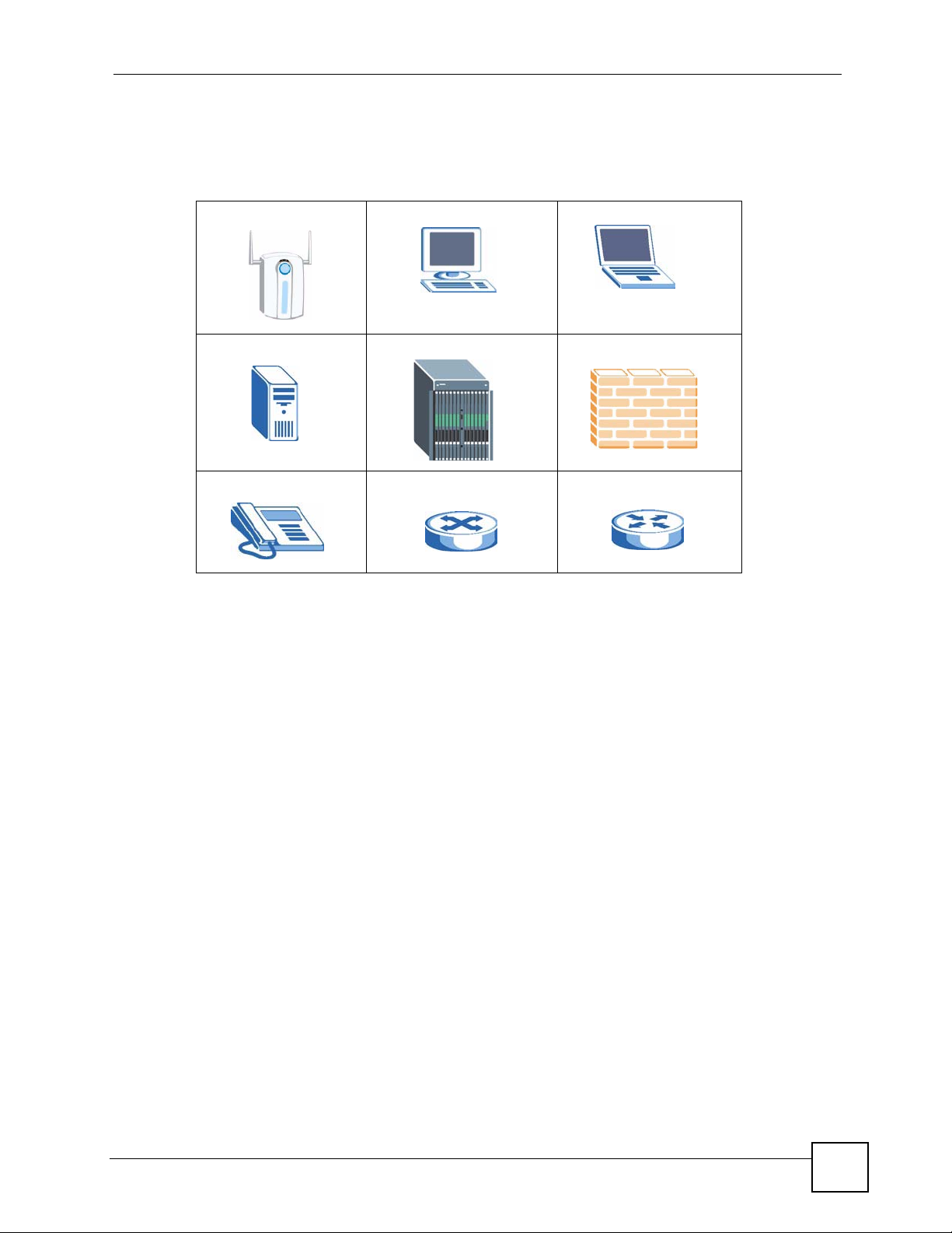
Icons Used in Figures
Figures in this User’s Guide may use the following generic icons. The ZyXEL Device icon is
not an exact representation of your device.
ZyXEL Device Computer Notebook computer
Server DSLAM Firewall
Telephone Switch Router
G-3000 Series User’s Guide
5
Page 6

Safety Warnings
Safety Warnings
1 For your safety, be sure to read and follow all warning notices and instructions.
• Do NOT use this product near water, for example, in a wet basement or near a swimming
pool.
• Do NOT expose your device to dampness, dust or corrosive liquids.
• Do NOT store things on the device.
• Do NOT install, use, or service this device during a thunderstorm. There is a remote risk
of electric shock from lightning.
• Connect ONLY suitable accessories to the device.
• ONLY qualified service personnel should service or disassemble this device.
• Make sure to connect the cables to the correct ports.
• Place connecting cables carefully so that no one will step on them or stumble over them.
• Always disconnect all cables from this device before servicing or disassembling.
• Use ONLY an appropriate power adaptor or cord for your device. Connect it to the right
supply voltage (for example, 110V AC in North America or 230V AC in Europe).
• Do NOT allow anything to rest on the power adaptor or cord and do NOT place the
product where anyone can walk on the power adaptor or cord.
• Do NOT use the device if the power adaptor or cord is damaged as it might cause
electrocution.
• If the power adaptor or cord is damaged, remove it from the power outlet.
• Do NOT attempt to repair the power adaptor or cord. Contact your local vendor to order a
new one.
• Do not use the device outside, and make sure all the connections are indoors. There is a
remote risk of electric shock from lightning.
• Antenna Warning! This device meets ETSI and FCC certification requirements when
using the included antenna(s). Only use the included antenna(s).
• If you wall mount your device, make sure that no electrical lines, gas or water pipes will
be damaged.
• The PoE (Power over Ethernet) devices that supply or receive power and their connected
Ethernet cables must all be completely indoors.
6
This product is recyclable. Dispose of it properly.
G-3000 Series User’s Guide
Page 7
Safety Warnings
G-3000 Series User’s Guide
7
Page 8

Safety Warnings
8
G-3000 Series User’s Guide
Page 9

Contents Overview
Contents Overview
Introduction ............................................................................................................................ 33
Introducing the ZyXEL Device ...................................................................................................35
Introducing the Web Configurator .............................................................................................. 41
Wizard Setup ............................................................................................................................. 45
Tutorial ....................................................................................................................................... 53
The Web Configurator ...........................................................................................................65
System Screens ........................................................................................................................ 67
Wireless Configuration ............................................................................................................. 73
Wireless Security Configuration ................................................................................................87
MESSID and SSID .................................................................................................................. 105
Other Wireless Configuration ...................................................................................................115
IP Screen ................................................................................................................................. 123
Remote Management Screens ................................................................................................ 127
Auth Server .............................................................................................................................. 141
Certificates ............................................................................................................................... 147
Log Screens ............................................................................................................................ 165
VLAN ....................................................................................................................................... 173
Maintenance ............................................................................................................................ 189
SMT and Troubleshooting ...................................................................................................199
Introducing the SMT ................................................................................................................ 201
General Setup ......................................................................................................................... 207
LAN Setup ............................................................................................................................... 209
Dial-in User Setup ................................................................................................................... 221
VLAN Setup ............................................................................................................................. 223
SNMP Configuration ................................................................................................................ 225
System Security ....................................................................................................................... 227
System Information and Diagnosis .......................................................................................... 231
Firmware and Configuration File Maintenance ........................................................................ 237
System Maintenance and Information ..................................................................................... 249
Troubleshooting ....................................................................................................................... 255
Appendices and Index ......................................................................................................... 259
G-3000 Series User’s Guide
9
Page 10

Contents Overview
10
G-3000 Series User’s Guide
Page 11

Table of Contents
Table of Contents
About This User's Guide ..........................................................................................................3
Document Conventions............................................................................................................4
Safety Warnings........................................................................................................................6
Contents Overview ...................................................................................................................9
Table of Contents.................................................................................................................... 11
List of Figures ......................................................................................................................... 21
List of Tables...........................................................................................................................29
Part I: Introduction................................................................................. 33
Chapter 1
Introducing the ZyXEL Device...............................................................................................35
1.1 Introducing the ZyXEL Device ............................................................................................ 35
1.2 Applications for the ZyXEL Device ...................................................................................... 35
1.2.1 Access Point .............................................................................................................. 36
1.2.2 Bridge / Repeater ....................................................................................................... 36
1.2.3 AP + Bridge ................................................................................................................ 37
1.2.4 MESSID (Multiple Extended Service Set IDentifier) ................................................... 38
1.3 Ways to Manage the ZyXEL Device .................................................................................... 39
1.4 Good Habits for Managing the ZyXEL Device ..................................................................... 40
Chapter 2
Introducing the Web Configurator ........................................................................................ 41
2.1 Web Configurator Overview ................................................................................................. 41
2.2 Accessing the Web Configurator ......................................................................................... 41
2.3 Resetting the ZyXEL Device ................................................................................................ 43
2.3.1 Methods of Restoring Factory-Defaults ...................................................................... 43
2.4 Navigating the Web Configurator ......................................................................................... 43
Chapter 3
Wizard Setup ........................................................................................................................... 45
3.1 Wizard Setup Overview ....................................................................................................... 45
3.1.1 Channel ...................................................................................................................... 45
G-3000 Series User’s Guide
11
Page 12

Table of Contents
3.1.2 ESS ID ....................................................................................................................... 45
3.1.3 WEP Encryption ......................................................................................................... 45
3.2 Wizard Setup: General Setup .............................................................................................. 46
3.3 Wizard Setup: Wireless LAN ............................................................................................... 46
3.4 Wizard Setup: IP Address ...................................................................................................48
3.4.1 IP Address Assignment .............................................................................................. 48
3.4.2 IP Address and Subnet Mask ..................................................................................... 48
3.5 Basic Setup Complete ......................................................................................................... 50
Chapter 4
Tutorial ..................................................................................................................................... 53
4.1 How to Configure the Wireless LAN .................................................................................... 53
4.1.1 Choosing the Wireless Mode ..................................................................................... 53
4.1.1.1 Configuring Dual WLAN Adapters .................................................................... 53
4.2 How to Configure Multiple Wireless Networks ..................................................................... 54
4.2.1 Change the Operating Mode ...................................................................................... 55
4.2.2 Configure the VoIP Network ....................................................................................... 56
4.2.2.1 Set Up Security for the VoIP Profile .................................................................. 58
4.2.2.2 Activate the VoIP Profile ................................................................................... 60
4.2.3 Configure the Guest Network ..................................................................................... 60
4.2.3.1 Set Up Security for the Guest Profile ................................................................ 61
4.2.3.2 Set up Layer-2 Isolation .................................................................................... 62
4.2.3.3 Activate the Guest Profile ................................................................................. 63
4.2.4 Testing the Wireless Networks ................................................................................... 64
Part II: The Web Configurator ............................................................... 65
Chapter 5
System Screens ...................................................................................................................... 67
5.1 System Overview ................................................................................................................. 67
5.2 Configuring General Setup ..................................................................................................67
5.3 Administrator Authentication on RADIUS ............................................................................ 68
5.4 Configuring Password ......................................................................................................... 68
5.5 Configuring Time Setting ..................................................................................................... 70
5.5.1 Resetting the Time ..................................................................................................... 71
Chapter 6
Wireless Configuration.......................................................................................................... 73
6.1 Wireless LAN Overview ....................................................................................................... 73
6.1.1 BSS ............................................................................................................................ 73
6.1.2 ESS ............................................................................................................................ 74
12
G-3000 Series User’s Guide
Page 13

Table of Contents
6.2 Wireless LAN Basics ........................................................................................................... 74
6.3 Quality of Service ................................................................................................................ 75
6.3.1 WMM QoS ..................................................................................................................75
6.3.1.1 WMM QoS Priorities ......................................................................................... 75
6.3.2 Type Of Service (ToS) ................................................................................................ 75
6.3.2.1 DiffServ ............................................................................................................. 75
6.3.2.2 DSCP and Per-Hop Behavior ........................................................................... 75
6.3.3 ToS (Type of Service) and WMM QoS ....................................................................... 76
6.4 Spanning Tree Protocol (STP) ............................................................................................. 76
6.4.1 Rapid STP .................................................................................................................. 76
6.4.2 STP Terminology ........................................................................................................ 76
6.4.3 How STP Works ......................................................................................................... 77
6.4.4 STP Port States ..........................................................................................................77
6.5 Wireless Screen Overview .................................................................................................. 78
6.6 Configuring Wireless Settings ............................................................................................. 78
6.6.1 Access Point Mode .................................................................................................... 78
6.6.2 Bridge/Repeater Mode ............................................................................................... 81
6.6.3 AP+Bridge Mode ........................................................................................................ 84
6.6.4 MESSID Mode ........................................................................................................... 85
Chapter 7
Wireless Security Configuration ........................................................................................... 87
7.1 Wireless Security Overview .................................................................................................87
7.1.1 Encryption .................................................................................................................. 87
7.1.2 Authentication ............................................................................................................ 87
7.1.3 Restricted Access ...................................................................................................... 87
7.1.4 Hide Identity ............................................................................................................... 88
7.1.5 WEP Encryption ......................................................................................................... 88
7.2 802.1x Overview .................................................................................................................. 88
7.3 EAP Authentication Overview .............................................................................................. 88
7.4 Introduction to WPA ............................................................................................................. 89
7.4.1 User Authentication ................................................................................................... 89
7.4.2 Encryption ................................................................................................................. 89
7.4.3 WPA(2)-PSK Application Example ............................................................................. 90
7.5 WPA(2) with RADIUS Application Example ......................................................................... 90
7.6 Security Modes .................................................................................................................... 91
7.7 Security Modes and Wireless Client Compatibility .............................................................. 92
7.8 Wireless Client WPA Supplicants ........................................................................................ 92
7.9 Wireless Security Effectiveness ........................................................................................... 93
7.10 Configuring Security .......................................................................................................... 93
7.10.1 Security: None ..........................................................................................................94
7.10.2 Security: No-Access ................................................................................................. 95
7.10.3 Security: WEP .......................................................................................................... 96
G-3000 Series User’s Guide
13
Page 14

Table of Contents
7.10.4 Security: 802.1x Only, 802.1x Static 64-bit, 802.1x Static 128-bit ............................ 97
7.10.5 Security: 802.1x Dynamic 64-bit or 802.1x Dynamic 128-bit ................................... 98
7.10.6 Security: WPA, WPA2, WPA-MIX or WPA2-MIX ...................................................... 99
7.10.7 Security: WPA-PSK, WPA2-PSK, WPA2-PSK-MIX ................................................ 100
7.11 Introduction to RADIUS ....................................................................................................102
7.12 Configuring RADIUS ........................................................................................................102
7.13 Configuring Local User Database .................................................................................... 104
Chapter 8
MESSID and SSID .................................................................................................................105
8.1 Wireless LAN Infrastructures ............................................................................................. 105
8.1.1 MESSID ...................................................................................................................105
8.1.2 Notes on Multiple ESS ............................................................................................. 105
8.1.3 Multiple ESS Example .............................................................................................. 105
8.1.4 Multiple ESS with VLAN Example ............................................................................ 106
8.1.5 Configuring Multiple ESSs ....................................................................................... 106
8.2 SSID .................................................................................................................................. 109
8.2.1 The SSID Screen ..................................................................................................... 109
8.2.2 Configuring SSID ...................................................................................................... 111
8.2.3 Second Rx VLAN ID ..................................................................................................113
Chapter 9
Other Wireless Configuration.............................................................................................. 115
9.1 Layer-2 Isolation Introduction .............................................................................................115
9.2 Configuring Layer-2 Isolation ..............................................................................................116
9.2.1 Layer-2 Isolation Examples .......................................................................................117
9.2.1.1 Layer-2 Isolation Example 1 ............................................................................117
9.2.1.2 Layer-2 Isolation Example 2 ............................................................................118
9.3 Configuring MAC Filter .......................................................................................................119
9.4 Configuring Roaming ......................................................................................................... 121
9.4.1 Requirements for Roaming ...................................................................................... 122
Chapter 10
IP Screen................................................................................................................................ 123
10.1 Factory Ethernet Defaults ................................................................................................ 123
10.2 TCP/IP Parameters .........................................................................................................123
10.2.1 WAN IP Address Assignment ................................................................................. 123
10.3 Configuring IP .................................................................................................................. 124
Chapter 11
Remote Management Screens............................................................................................. 127
14
11.1 Remote Management Overview ...................................................................................... 127
11.1.1 Remote Management Limitations ........................................................................... 127
G-3000 Series User’s Guide
Page 15

Table of Contents
11.1.2 System Timeout ..................................................................................................... 128
11.2 Configuring Telnet ............................................................................................................ 128
11.3 Configuring FTP ............................................................................................................... 129
11.4 WWW (HTTP and HTTPS) ............................................................................................. 129
11.5 Configuring WWW ...........................................................................................................130
11.6 HTTPS Example .............................................................................................................. 132
11.6.1 Internet Explorer Warning Messages ..................................................................... 132
11.6.2 Netscape Navigator Warning Messages ................................................................ 133
11.6.3 Avoiding the Browser Warning Messages .............................................................. 134
11.6.4 Login Screen .......................................................................................................... 134
11.7 SNMP ............................................................................................................................... 137
11.7.1 Supported MIBs ...................................................................................................... 138
11.7.2 SNMP Traps ........................................................................................................... 138
11.8 SNMP Traps .................................................................................................................... 139
11.8.1 Configuring SNMP .................................................................................................. 139
Chapter 12
Auth Server............................................................................................................................ 141
12.1 Auth Server Overview ......................................................................................................141
12.2 Internal RADIUS Server Setting ...................................................................................... 142
12.3 Trusted AP Overview .......................................................................................................144
12.4 Configuring Trusted AP ................................................................................................... 144
12.5 Trusted Users Overview .................................................................................................. 146
Chapter 13
Certificates ............................................................................................................................147
13.1 Certificates Overview ....................................................................................................... 147
13.1.1 Advantages of Certificates ..................................................................................... 148
13.2 Self-signed Certificates .................................................................................................... 148
13.3 Verifying a Certificate ....................................................................................................... 148
13.3.1 Checking the Fingerprint of a Certificate on Your Computer .................................. 148
13.4 Configuration Summary ................................................................................................... 149
13.5 My Certificates ................................................................................................................. 149
13.6 Certificate File Formats .................................................................................................... 151
13.7 Importing a Certificate ..................................................................................................... 152
13.8 Creating a Certificate ....................................................................................................... 153
13.9 My Certificate Details ....................................................................................................... 156
13.10 Trusted CAs ................................................................................................................... 159
13.11 Importing a Trusted CA’s Certificate .............................................................................. 161
13.12 Trusted CA Certificate Details ....................................................................................... 162
Chapter 14
Log Screens ..........................................................................................................................165
G-3000 Series User’s Guide
15
Page 16

Table of Contents
14.1 Configuring View Log ....................................................................................................... 165
14.2 Configuring Log Settings ................................................................................................. 167
14.3 Example Log Messages .................................................................................................. 169
14.4 Log Commands ............................................................................................................... 170
14.4.1 Configuring What You Want the ZyXEL Device to Log .......................................... 170
14.4.2 Displaying Logs ...................................................................................................... 171
14.5 Log Command Example .................................................................................................. 171
Chapter 15
VLAN ...................................................................................................................................... 173
15.1 VLAN ............................................................................................................................... 173
15.1.1 Management VLAN ID ........................................................................................... 173
15.1.2 VLAN Tagging ........................................................................................................ 173
15.2 Configuring VLAN ............................................................................................................ 174
15.2.1 VLAN ...................................................................................................................... 174
15.2.2 Configuring Management VLAN Example ............................................................. 176
15.2.3 Configuring Microsoft’s IAS Server Example ......................................................... 178
15.2.3.1 Configuring VLAN Groups ............................................................................ 179
15.2.3.2 Configuring Remote Access Policies ............................................................ 180
15.2.4 Second Rx VLAN ID Example ................................................................................ 186
15.2.4.1 Second Rx VLAN Setup Example ................................................................ 187
Chapter 16
Maintenance .......................................................................................................................... 189
16.1 Maintenance Overview .................................................................................................... 189
16.2 System Status Screen ..................................................................................................... 189
16.2.1 System Statistics .................................................................................................... 190
16.3 Association List ................................................................................................................ 191
16.4 Channel Usage ................................................................................................................ 192
16.5 F/W Upload Screen .........................................................................................................193
16.6 Configuration Screen ....................................................................................................... 195
16.6.1 Backup Configuration ............................................................................................. 196
16.6.2 Restore Configuration ........................................................................................... 196
16.6.3 Back to Factory Defaults ........................................................................................ 197
16.7 Restart Screen ................................................................................................................. 197
Part III: SMT and Troubleshooting...................................................... 199
Chapter 17
Introducing the SMT .............................................................................................................201
16
17.1 Accessing the SMT via the Console Port ........................................................................ 201
G-3000 Series User’s Guide
Page 17

Table of Contents
17.1.1 Initial Screen ..........................................................................................................201
17.2 Connect to your ZyXEL Device Using Telnet ................................................................... 202
17.3 Entering the Password .................................................................................................... 202
17.4 Changing the System Password ..................................................................................... 202
17.5 Navigating the SMT Interface .......................................................................................... 203
17.5.1 SMT Main Menu Summary .................................................................................... 204
17.6 SMT Menus Overview .................................................................................................... 205
Chapter 18
General Setup........................................................................................................................ 207
18.1 General Setup ................................................................................................................. 207
18.1.1 Procedure To Configure Menu 1 ............................................................................ 207
Chapter 19
LAN Setup.............................................................................................................................. 209
19.1 LAN Setup ....................................................................................................................... 209
19.2 TCP/IP Ethernet Setup .................................................................................................... 209
19.3 Wireless LAN Setup ........................................................................................................210
19.3.1 Configuring MAC Address Filter ............................................................................. 212
19.3.2 Configuring Roaming ............................................................................................. 214
19.3.3 Configuring Bridge Link .......................................................................................... 215
19.3.4 Configuring Layer-2 Isolation ................................................................................. 217
19.3.5 Configuring SSID Profiles ...................................................................................... 218
Chapter 20
Dial-in User Setup................................................................................................................. 221
20.1 Dial-in User Setup ........................................................................................................... 221
Chapter 21
VLAN Setup ...........................................................................................................................223
21.1 VLAN Setup ..................................................................................................................... 223
Chapter 22
SNMP Configuration.............................................................................................................225
22.1 SNMP Configuration ........................................................................................................225
Chapter 23
System Security.................................................................................................................... 227
23.1 System Password ............................................................................................................ 227
23.2 Configuring Wireless Security Profiles ............................................................................ 227
Chapter 24
System Information and Diagnosis..................................................................................... 231
G-3000 Series User’s Guide
17
Page 18

Table of Contents
24.1 System Status .................................................................................................................. 231
24.2 System Information .......................................................................................................... 233
24.2.1 System Information ................................................................................................ 233
24.2.2 Console Port Speed ............................................................................................... 234
24.3 Log and Trace .................................................................................................................. 234
24.3.1 Viewing Error Log ................................................................................................... 234
24.4 Diagnostic ........................................................................................................................ 235
Chapter 25
Firmware and Configuration File Maintenance..................................................................237
25.1 Filename Conventions ..................................................................................................... 237
25.2 Backup Configuration ......................................................................................................238
25.2.1 Backup Configuration Using FTP ........................................................................... 238
25.2.2 Using the FTP Command from the DOS Prompt ................................................... 239
25.2.3 Backup Configuration Using TFTP ......................................................................... 240
25.2.4 Example: TFTP Command ..................................................................................... 240
25.2.5 Backup Via Console Port ....................................................................................... 241
25.3 Restore Configuration ..................................................................................................... 242
25.3.1 Restore Using FTP ................................................................................................. 242
25.4 Uploading Firmware and Configuration Files .................................................................. 242
25.4.1 Firmware Upload .................................................................................................... 243
25.4.2 Configuration File Upload ....................................................................................... 243
25.4.3 Using the FTP command from the DOS Prompt Example ..................................... 244
25.4.4 TFTP File Upload ................................................................................................... 245
25.4.5 Example: TFTP Command ..................................................................................... 246
25.4.6 Uploading Via Console Port ................................................................................... 246
25.4.7 Uploading Firmware File Via Console Port ............................................................ 246
25.4.8 Example Xmodem Firmware Upload Using HyperTerminal ................................... 246
25.4.9 Uploading Configuration File Via Console Port ...................................................... 247
25.4.10 Example Xmodem Configuration Upload Using HyperTerminal ........................... 248
Chapter 26
System Maintenance and Information ................................................................................249
26.1 Command Interpreter Mode ............................................................................................ 249
26.1.1 Command Syntax ................................................................................................... 250
26.1.2 Command Usage ................................................................................................... 250
26.1.3 Brute-Force Password Guessing Protection .......................................................... 250
26.1.3.1 Configuring Brute-Force Password Guessing Protection: Example ............. 250
26.2 Time and Date Setting .....................................................................................................251
26.3 Remote Management Setup ............................................................................................ 252
26.3.1 Telnet ...................................................................................................................... 252
26.3.2 FTP ........................................................................................................................ 252
26.3.3 Web ........................................................................................................................ 252
18
G-3000 Series User’s Guide
Page 19

Table of Contents
26.3.4 Remote Management Setup .................................................................................. 253
26.3.5 Remote Management Limitations .......................................................................... 254
26.4 System Timeout ............................................................................................................... 254
Chapter 27
Troubleshooting.................................................................................................................... 255
27.1 Power, Hardware Connections, and LEDs ...................................................................... 255
27.2 ZyXEL Device Access and Login .................................................................................... 255
27.3 Internet Access ................................................................................................................ 257
Part IV: Appendices and Index ........................................................... 259
Appendix A Product Specifications.......................................................................................261
Appendix B Setting up Your Computer’s IP Address............................................................ 267
Appendix C IP Addresses and Subnetting ........................................................................... 283
Appendix D IP Address Assignment Conflicts......................................................................291
Appendix E Wireless LANs ..................................................................................................295
Appendix F Pop-up Windows, JavaScripts and Java Permissions ...................................... 309
Appendix G Importing Certificates........................................................................................ 315
Appendix H Text File Based Auto Configuration ..................................................................327
Appendix I Wireless LAN Manager ......................................................................................335
Appendix J Legal Information ...............................................................................................349
Appendix K Customer Support .............................................................................................353
Index....................................................................................................................................... 357
G-3000 Series User’s Guide
19
Page 20

Table of Contents
20
G-3000 Series User’s Guide
Page 21

List of Figures
List of Figures
Figure 1 Access Point Application .......................................................................................................... 36
Figure 2 Bridge Application .................................................................................................................... 37
Figure 3 Repeater Application ................................................................................................................ 37
Figure 4 AP+Bridge Application ............................................................................................................. 38
Figure 5 Multiple BSSs ........................................................................................................................... 39
Figure 6 Change Password Screen ........................................................................................................ 42
Figure 7 Replace Certificate Screen ....................................................................................................... 42
Figure 8 The MAIN MENU Screen of the Web Configurator .................................................................. 43
Figure 9 Wizard 1 : General Setup ......................................................................................................... 46
Figure 10 Wizard 2 : Wireless LAN Setup .............................................................................................. 47
Figure 11 Wizard 3 : IP Address Assignment ......................................................................................... 49
Figure 12 Wizard 4 : Setup Complete .................................................................................................... 51
Figure 13 Tutorial: Example MESSID Setup .......................................................................................... 54
Figure 14 Tutorial: Wireless LAN: Before ............................................................................................... 55
Figure 15 Tutorial: Wireless LAN: Change Mode ................................................................................... 56
Figure 16 Tutorial: WIRELESS > SSID .................................................................................................. 57
Figure 17 Tutorial: VoIP SSID Profile Edit .............................................................................................. 58
Figure 18 Tutorial: VoIP Security ............................................................................................................ 59
Figure 19 Tutorial: VoIP Security Profile Edit .......................................................................................... 59
Figure 20 Tutorial: VoIP Security: Updated ............................................................................................ 60
Figure 21 Tutorial: Activate VoIP Profile ................................................................................................. 60
Figure 22 Tutorial: Guest Edit ................................................................................................................. 61
Figure 23 Tutorial: Guest Security Profile Edit ........................................................................................ 62
Figure 24 Tutorial: Guest Security: Updated .......................................................................................... 62
Figure 25 Tutorial: Layer 2 Isolation ....................................................................................................... 63
Figure 26 Tutorial: Activate Guest Profile ............................................................................................... 63
Figure 27 System General Setup ........................................................................................................... 67
Figure 28 Password. ............................................................................................................................... 69
Figure 29 Time Setting ........................................................................................................................... 70
Figure 30 Basic Service set .................................................................................................................... 73
Figure 31 Extended Service Set ............................................................................................................. 74
Figure 32 DiffServ: Differentiated Service Field ...................................................................................... 76
Figure 33 Wireless: Access Point ........................................................................................................... 79
Figure 34 Bridging Example ................................................................................................................... 81
Figure 35 Bridge Loop: Two Bridges Connected to Switch .................................................................... 82
Figure 36 Bridge Loop: Bridge Connected to Wired LAN ....................................................................... 82
Figure 37 Wireless: Bridge/Repeater ..................................................................................................... 83
Figure 38 Wireless: AP+Bridge .............................................................................................................. 84
G-3000 Series User’s Guide
21
Page 22

List of Figures
Figure 39 EAP Authentication ................................................................................................................ 88
Figure 40 WPA(2)-PSK Authentication ................................................................................................... 90
Figure 41 WPA(2) with RADIUS Application Example ........................................................................... 91
Figure 42 Security .................................................................................................................................. 94
Figure 43 Security: None ........................................................................................................................ 95
Figure 44 Security: No-Access ............................................................................................................... 95
Figure 45 Security: WEP ........................................................................................................................ 96
Figure 46 Security: 802.1x Static 64-bit, 802.1x Static 128-bit .............................................................. 97
Figure 47 Security: WPA, 802.1x Dynamic 64-bit, 802.1x Dynamic 128-bit or WPA-MIX ..................... 99
Figure 48 Security:WPA2 or WPA2-MIX ............................................................................................... 100
Figure 49 Security: WPA-PSK, WPA2-PSK or WPA2-PSK-MIX ........................................................... 101
Figure 50 RADIUS ................................................................................................................................ 102
Figure 51 Local User Database ........................................................................................................... 104
Figure 52 Multiple ESS with VLAN Example ........................................................................................ 106
Figure 53 Wireless: Multiple ESS ......................................................................................................... 107
Figure 54 SSID ......................................................................................................................................110
Figure 55 Configuring SSID ...................................................................................................................111
Figure 56 Second Rx VLAN ID Example ...............................................................................................113
Figure 57 Configuring SSID: Second Rx VLAN ID Example .................................................................114
Figure 58 Layer-2 Isolation Application .................................................................................................115
Figure 59 Layer-2 Isolation Configuration Screen .................................................................................116
Figure 60 Layer-2 Isolation Example .....................................................................................................117
Figure 61 Layer-2 Isolation Example 1 ..................................................................................................118
Figure 62 Layer-2 Isolation Example 2 ..................................................................................................119
Figure 63 MAC Address Filter .............................................................................................................. 120
Figure 64 Roaming Example ................................................................................................................ 121
Figure 65 Roaming ............................................................................................................................... 122
Figure 66 IP Setup ................................................................................................................................ 124
Figure 67 Remote Management: Telnet ............................................................................................... 128
Figure 68 Remote Management: FTP .................................................................................................. 129
Figure 69 HTTPS Implementation ........................................................................................................ 130
Figure 70 Remote Management: WWW ...............................................................................................131
Figure 71 Security Alert Dialog Box (Internet Explorer) ........................................................................132
Figure 72 Security Certificate 1 (Netscape) .......................................................................................... 133
Figure 73 Security Certificate 2 (Netscape) .......................................................................................... 133
Figure 74 Example: Lock Denoting a Secure Connection) ................................................................... 135
Figure 75 Replace Certificate ............................................................................................................... 135
Figure 76 Device-specific Certificate .................................................................................................... 136
Figure 77 Common ZyXEL Device Certificate ......................................................................................136
Figure 78 SNMP Management Model .................................................................................................. 137
Figure 79 Remote Management: SNMP ..............................................................................................140
Figure 80 ZyXEL Device Authenticates Wireless Stations ................................................................... 141
Figure 81 ZyXEL Device Authenticates other AP’s .............................................................................. 142
22
G-3000 Series User’s Guide
Page 23

List of Figures
Figure 82 Internal RADIUS Server Setting Screen .............................................................................. 143
Figure 83 Trusted AP Overview ............................................................................................................ 144
Figure 84 Trusted AP Screen ............................................................................................................... 145
Figure 85 Certificates on Your Computer ............................................................................................. 148
Figure 86 Certificate Details ................................................................................................................ 149
Figure 87 My Certificates ...................................................................................................................... 150
Figure 88 My Certificate Import ............................................................................................................ 153
Figure 89 My Certificate Create ............................................................................................................ 154
Figure 90 My Certificate Details ........................................................................................................... 157
Figure 91 Trusted CAs .......................................................................................................................... 160
Figure 92 Trusted CA Import ................................................................................................................ 161
Figure 93 Trusted CA Details ............................................................................................................... 162
Figure 94 View Log ............................................................................................................................... 166
Figure 95 Log Settings ......................................................................................................................... 167
Figure 96 VLAN .................................................................................................................................... 175
Figure 97 Management VLAN Configuration Example ......................................................................... 176
Figure 98 VLAN-Aware Switch - Static VLAN ....................................................................................... 177
Figure 99 VLAN-Aware Switch ............................................................................................................. 177
Figure 100 VLAN-Aware Switch - VLAN Status .................................................................................... 177
Figure 101 VLAN Setup ........................................................................................................................ 178
Figure 102 New Global Security Group ............................................................................................... 179
Figure 103 Add Group Members ......................................................................................................... 180
Figure 104 New Remote Access Policy for VLAN Group .................................................................... 181
Figure 105 Specifying Windows-Group Condition ................................................................................ 181
Figure 106 Adding VLAN Group .......................................................................................................... 181
Figure 107 Granting Permissions and User Profile Screens ............................................................... 182
Figure 108 Authentication Tab Settings ................................................................................................ 182
Figure 109 Encryption Tab Settings ..................................................................................................... 183
Figure 110 Connection Attributes Screen ............................................................................................ 183
Figure 111 RADIUS Attribute Screen ................................................................................................... 184
Figure 112 802 Attribute Setting for Tunnel-Medium-Type .................................................................. 184
Figure 113 VLAN ID Attribute Setting for Tunnel-Pvt-Group-ID ........................................................... 185
Figure 114 VLAN Attribute Setting for Tunnel-Type .............................................................................185
Figure 115 Completed Advanced Tab ................................................................................................. 186
Figure 116 Second Rx VLAN ID Example ............................................................................................ 187
Figure 117 Configuring SSID: Second Rx VLAN ID Example .............................................................. 188
Figure 118 System Status ..................................................................................................................... 189
Figure 119 System Status: Show Statistics ........................................................................................... 190
Figure 120 Association List .................................................................................................................. 191
Figure 121 Channel Usage ................................................................................................................... 192
Figure 122 Firmware Upload ................................................................................................................ 193
Figure 123 Firmware Upload In Process .............................................................................................. 194
Figure 124 Network Temporarily Disconnected ....................................................................................194
G-3000 Series User’s Guide
23
Page 24

List of Figures
Figure 125 Firmware Upload Error ....................................................................................................... 195
Figure 126 Configuration ...................................................................................................................... 195
Figure 127 Configuration Upload Successful ....................................................................................... 196
Figure 128 Network Temporarily Disconnected ....................................................................................196
Figure 129 Configuration Upload Error ................................................................................................. 197
Figure 130 Reset Warning Message .................................................................................................... 197
Figure 131 Restart Screen ................................................................................................................... 198
Figure 132 Initial Screen ....................................................................................................................... 201
Figure 133 Login ................................................................................................................................... 202
Figure 134 Menu 23 System Security .................................................................................................. 202
Figure 135 Menu 23.1 System Security: Change Password ................................................................ 203
Figure 136 SMT Main Menu ................................................................................................................. 204
Figure 137 Menu 1 General Setup ....................................................................................................... 207
Figure 138 Menu 3 LAN Setup ............................................................................................................ 209
Figure 139 Menu 3.2 TCP/IP Setup ..................................................................................................... 209
Figure 140 Menu 3.5 Wireless LAN Setup ........................................................................................... 210
Figure 141 Menu 3.5 Wireless LAN Setup ........................................................................................... 213
Figure 142 Menu 3.5.1 WLAN MAC Address Filter .............................................................................. 213
Figure 143 Menu 3.5 Wireless LAN Setup ........................................................................................... 214
Figure 144 Menu 3.5.2 - Roaming Configuration ................................................................................ 215
Figure 145 Menu 3.5 Wireless LAN Setup ........................................................................................... 216
Figure 146 Menu 3.5.4 Bridge Link Configuration ................................................................................216
Figure 147 Menu 3.5 Wireless LAN Setup ........................................................................................... 217
Figure 148 Menu 3.5.5 - Layer-2 Isolation ............................................................................................ 218
Figure 149 Menu 3.5 Wireless LAN Setup ........................................................................................... 219
Figure 150 Menu 3.5.6 - SSID Profile Edit ........................................................................................... 219
Figure 151 Menu 14- Dial-in User Setup .............................................................................................. 221
Figure 152 Menu 14.1- Edit Dial-in User .............................................................................................. 221
Figure 153 Menu 16 VLAN Setup ......................................................................................................... 224
Figure 154 Menu 22 SNMP Configuration ............................................................................................ 225
Figure 155 Menu 23 System Security .................................................................................................. 227
Figure 156 Menu 23.5 - Security Profile Edit ........................................................................................ 228
Figure 157 Menu 24 System Maintenance ........................................................................................... 231
Figure 158 Menu 24.1 System Maintenance: Status ............................................................................ 232
Figure 159 Menu 24.2 System Information and Console Port Speed .................................................. 233
Figure 160 Menu 24.2.1 System Information: Information ................................................................... 233
Figure 161 Menu 24.2.2 System Maintenance: Change Console Port Speed ..................................... 234
Figure 162 Menu 24.3 System Maintenance: Log and Trace ............................................................... 235
Figure 163 Sample Error and Information Messages ........................................................................... 235
Figure 164 Menu 24.4 System Maintenance: Diagnostic ..................................................................... 235
Figure 165 Menu 24.5 Backup Configuration ....................................................................................... 238
Figure 166 FTP Session Example ........................................................................................................ 239
Figure 167 System Maintenance: Backup Configuration ..................................................................... 241
24
G-3000 Series User’s Guide
Page 25

List of Figures
Figure 168 System Maintenance: Starting Xmodem Download Screen ............................................... 241
Figure 169 Backup Configuration Example .......................................................................................... 241
Figure 170 Successful Backup Confirmation Screen ........................................................................... 241
Figure 171 Menu 24.6 Restore Configuration ...................................................................................... 242
Figure 172 Menu 24.7 System Maintenance: Upload Firmware .......................................................... 243
Figure 173 Menu 24.7.1 System Maintenance: Upload System Firmware .......................................... 243
Figure 174 Menu 24.7.2 System Maintenance: Upload System Configuration File ............................. 244
Figure 175 FTP Session Example ........................................................................................................ 245
Figure 176 Menu 24.7.1 as seen using the Console Port .................................................................... 246
Figure 177 Example Xmodem Upload .................................................................................................. 247
Figure 178 Menu 24.7.2 as seen using the Console Port ................................................................... 247
Figure 179 Example Xmodem Upload .................................................................................................. 248
Figure 180 Menu 24 System Maintenance ........................................................................................... 249
Figure 181 Valid CI Commands ............................................................................................................ 250
Figure 182 Menu 24.10 System Maintenance: Time and Date Setting ................................................ 251
Figure 183 Telnet Configuration on a TCP/IP Network ......................................................................... 252
Figure 184 Menu 24.11 Remote Management Control ........................................................................ 253
Figure 185 WIndows 95/98/Me: Network: Configuration ...................................................................... 268
Figure 186 Windows 95/98/Me: TCP/IP Properties: IP Address .......................................................... 269
Figure 187 Windows 95/98/Me: TCP/IP Properties: DNS Configuration .............................................. 270
Figure 188 Windows XP: Start Menu .................................................................................................... 271
Figure 189 Windows XP: Control Panel ............................................................................................... 271
Figure 190 Windows XP: Control Panel: Network Connections: Properties ......................................... 272
Figure 191 Windows XP: Local Area Connection Properties ............................................................... 272
Figure 192 Windows XP: Internet Protocol (TCP/IP) Properties .......................................................... 273
Figure 193 Windows XP: Advanced TCP/IP Properties ....................................................................... 274
Figure 194 Windows XP: Internet Protocol (TCP/IP) Properties .......................................................... 275
Figure 195 Macintosh OS 8/9: Apple Menu .......................................................................................... 276
Figure 196 Macintosh OS 8/9: TCP/IP ................................................................................................. 276
Figure 197 Macintosh OS X: Apple Menu ............................................................................................ 277
Figure 198 Macintosh OS X: Network .................................................................................................. 278
Figure 199 Red Hat 9.0: KDE: Network Configuration: Devices ......................................................... 279
Figure 200 Red Hat 9.0: KDE: Ethernet Device: General .................................................................. 279
Figure 201 Red Hat 9.0: KDE: Network Configuration: DNS ............................................................... 280
Figure 202 Red Hat 9.0: KDE: Network Configuration: Activate ........................................................ 280
Figure 203 Red Hat 9.0: Dynamic IP Address Setting in ifconfig-eth0 ............................................... 281
Figure 204 Red Hat 9.0: Static IP Address Setting in ifconfig-eth0 ................................................... 281
Figure 205 Red Hat 9.0: DNS Settings in resolv.conf ........................................................................ 281
Figure 206 Red Hat 9.0: Restart Ethernet Card ................................................................................. 281
Figure 207 Red Hat 9.0: Checking TCP/IP Properties ....................................................................... 282
Figure 208 Network Number and Host ID ............................................................................................ 284
Figure 209 Subnetting Example: Before Subnetting ............................................................................ 286
Figure 210 Subnetting Example: After Subnetting ............................................................................... 287
G-3000 Series User’s Guide
25
Page 26

List of Figures
Figure 211 IP Address Conflicts: Case A .............................................................................................. 291
Figure 212 IP Address Conflicts: Case B ............................................................................................. 292
Figure 213 IP Address Conflicts: Case C ............................................................................................. 292
Figure 214 IP Address Conflicts: Case D ............................................................................................. 293
Figure 215 Peer-to-Peer Communication in an Ad-hoc Network ......................................................... 295
Figure 216 Basic Service Set ............................................................................................................... 296
Figure 217 Infrastructure WLAN ........................................................................................................... 297
Figure 218 RTS/CTS ........................................................................................................................... 298
Figure 219 WPA(2) with RADIUS Application Example ....................................................................... 305
Figure 220 WPA(2)-PSK Authentication ............................................................................................... 306
Figure 221 Pop-up Blocker ................................................................................................................... 309
Figure 222 Internet Options: Privacy .................................................................................................... 310
Figure 223 Internet Options: Privacy .....................................................................................................311
Figure 224 Pop-up Blocker Settings ......................................................................................................311
Figure 225 Internet Options: Security ................................................................................................... 312
Figure 226 Security Settings - Java Scripting ....................................................................................... 313
Figure 227 Security Settings - Java ...................................................................................................... 313
Figure 228 Java (Sun) .......................................................................................................................... 314
Figure 229 Security Certificate ............................................................................................................. 315
Figure 230 Login Screen ...................................................................................................................... 316
Figure 231 Certificate General Information before Import .................................................................... 316
Figure 232 Certificate Import Wizard 1 ................................................................................................. 317
Figure 233 Certificate Import Wizard 2 ................................................................................................. 317
Figure 234 Certificate Import Wizard 3 ................................................................................................. 318
Figure 235 Root Certificate Store ......................................................................................................... 318
Figure 236 Certificate General Information after Import ....................................................................... 319
Figure 237 ZyXEL Device Trusted CA Screen ..................................................................................... 320
Figure 238 CA Certificate Example ...................................................................................................... 321
Figure 239 Personal Certificate Import Wizard 1 .................................................................................. 321
Figure 240 Personal Certificate Import Wizard 2 .................................................................................. 322
Figure 241 Personal Certificate Import Wizard 3 .................................................................................. 322
Figure 242 Personal Certificate Import Wizard 4 .................................................................................. 323
Figure 243 Personal Certificate Import Wizard 5 .................................................................................. 323
Figure 244 Personal Certificate Import Wizard 6 .................................................................................. 323
Figure 245 Access the ZyXEL Device Via HTTPS ............................................................................... 324
Figure 246 SSL Client Authentication ................................................................................................... 324
Figure 247 ZyXEL Device Secure Login Screen .................................................................................. 324
Figure 248 Text File Based Auto Configuration .................................................................................... 327
Figure 249 Configuration File Format ................................................................................................... 329
Figure 250 WEP Configuration File Example ....................................................................................... 330
Figure 251 802.1X Configuration File Example .................................................................................... 331
Figure 252 WPA-PSK Configuration File Example ............................................................................... 331
Figure 253 WPA Configuration File Example ....................................................................................... 332
26
G-3000 Series User’s Guide
Page 27

List of Figures
Figure 254 wlan Configuration File Example ........................................................................................ 333
Figure 255 EMS Installation Wizard: Welcome Screen ....................................................................... 336
Figure 256 EMS Installation Wizard: Choose Destination Screen ...................................................... 336
Figure 257 EMS Installation Wizard: Complete Screen ...................................................................... 337
Figure 258 Starting the SNMPc Network Manager .............................................................................. 338
Figure 259 Accessing the SNMPc Startup Settings ............................................................................ 338
Figure 260 SNMPc Task Setup Screen ............................................................................................... 339
Figure 261 Accessing the Compile Mibs Screen .................................................................................. 339
Figure 262 Compile Mibs Screen ........................................................................................................ 340
Figure 263 Add Mib files Screen .......................................................................................................... 340
Figure 264 Compile Mibs Screen ........................................................................................................ 340
Figure 265 Compile Mibs Confirm Screen ............................................................................................ 341
Figure 266 Compile Mib OK Screen .................................................................................................... 341
Figure 267 Selecting the Root Subnet ................................................................................................ 342
Figure 268 Accessing the MAP Object Properties Screen ................................................................... 342
Figure 269 MAP Object Properties: General ...................................................................................... 342
Figure 270 MAP Object Properties: Access ......................................................................................... 343
Figure 271 Device Icon ......................................................................................................................... 343
Figure 272 Accessing the Discovery/Polling Agents Screen ................................................................ 344
Figure 273 Discovery/Polling Agents Screen ....................................................................................... 344
Figure 274 Device Icon ......................................................................................................................... 345
Figure 275 MAP Object Properties: Access ......................................................................................... 345
Figure 276 WLM EMS Screen ............................................................................................................ 346
G-3000 Series User’s Guide
27
Page 28

List of Figures
28
G-3000 Series User’s Guide
Page 29

List of Tables
List of Tables
Table 1 Wizard 1 : General Setup .......................................................................................................... 46
Table 2 Wizard 2 : Wireless LAN Setup ................................................................................................. 47
Table 3 Private IP Address Ranges ....................................................................................................... 48
Table 4 Wizard 3 : IP Address Assignment ........................................................................................... 49
Table 5 Tutorial: Example Information ................................................................................................... 55
Table 6 System General Setup .............................................................................................................. 67
Table 7 Password .................................................................................................................................. 69
Table 8 Time Setting .............................................................................................................................. 71
Table 9 WMM QoS Priorities ................................................................................................................. 75
Table 10 ToS and IEEE 802.1d to WMM QoS Priority Level Mapping .................................................. 76
Table 11 STP Path Costs ....................................................................................................................... 77
Table 12 STP Port States ...................................................................................................................... 77
Table 13 Wireless: Access Point ........................................................................................................... 79
Table 14 Wireless: Bridge/Repeater ...................................................................................................... 83
Table 15 Security Modes ....................................................................................................................... 91
Table 16 Security Modes for ZyXEL Device and Windows XP Wireless Client ..................................... 92
Table 17 Wireless Security Levels ......................................................................................................... 93
Table 18 Security ................................................................................................................................... 94
Table 19 Security: No-Access ................................................................................................................ 95
Table 20 Security: No-Access ................................................................................................................ 95
Table 21 Security: WEP ......................................................................................................................... 96
Table 22 Security: 802.1x Static 64-bit, 802.1x Static 128-bit ................................................................97
Table 23 Security: 802.1x Dynamic 64-bit or 802.1x Dynamic 128-bit .................................................. 99
Table 24 Security: WPA2 or WPA2-MIX .............................................................................................. 100
Table 25 Security: WPA-PSK, WPA2-PSK or WPA2-PSK-MIX ........................................................... 101
Table 26 RADIUS ................................................................................................................................ 103
Table 27 Local User Database ............................................................................................................ 104
Table 28 Wireless: Multiple ESS .......................................................................................................... 107
Table 29 SSID .......................................................................................................................................110
Table 30 Configuring SSID ................................................................................................................... 111
Table 31 Layer-2 Isolation Configuration ..............................................................................................117
Table 32 MAC Address Filter ............................................................................................................... 120
Table 33 Roaming ................................................................................................................................ 122
Table 34 Private IP Address Ranges ................................................................................................... 123
Table 35 IP Setup ................................................................................................................................ 124
Table 36 Remote Management Overview ...........................................................................................127
Table 37 Remote Management: Telnet ................................................................................................ 128
Table 38 Remote Management: FTP ................................................................................................... 129
G-3000 Series User’s Guide
29
Page 30

List of Tables
Table 39 Remote Management: WWW ...............................................................................................131
Table 40 SNMP Traps .......................................................................................................................... 138
Table 41 SNMP Interface Index to Physical Port Mapping .................................................................. 139
Table 42 Remote Management: SNMP ............................................................................................... 140
Table 43 Internal RADIUS Server ........................................................................................................ 142
Table 44 My Certificates ...................................................................................................................... 143
Table 45 Trusted AP ............................................................................................................................ 145
Table 46 My Certificates ...................................................................................................................... 150
Table 47 My Certificate Import ............................................................................................................. 153
Table 48 My Certificate Create ............................................................................................................ 154
Table 49 My Certificate Details ............................................................................................................ 158
Table 50 Trusted CAs .......................................................................................................................... 160
Table 51 Trusted CA Import ................................................................................................................. 161
Table 52 Trusted CA Details ................................................................................................................ 163
Table 53 View Log ............................................................................................................................... 166
Table 54 Log Settings .......................................................................................................................... 168
Table 55 System Maintenance Logs .................................................................................................... 169
Table 56 ICMP Notes ........................................................................................................................... 169
Table 57 Sys log .................................................................................................................................. 170
Table 58 Log Categories and Available Settings ................................................................................. 170
Table 59 WIRELESS VLAN ................................................................................................................. 175
Table 60 Standard RADIUS Attributes ................................................................................................. 178
Table 61 System Status ....................................................................................................................... 189
Table 62 System Status: Show Statistics ............................................................................................. 190
Table 63 Association List ..................................................................................................................... 191
Table 64 Channel Usage ..................................................................................................................... 193
Table 65 Firmware Upload ................................................................................................................... 194
Table 66 Restore Configuration ........................................................................................................... 196
Table 67 Main Menu Commands ......................................................................................................... 203
Table 68 Main Menu Summary ............................................................................................................ 204
Table 69 SMT Menus Overview ........................................................................................................... 205
Table 70 Menu 1 General Setup .......................................................................................................... 207
Table 71 Menu 3.2 TCP/IP Setup ........................................................................................................ 210
Table 72 Menu 3.5 Wireless LAN Setup ...............................................................................................211
Table 73 Menu 3.5.1 WLAN MAC Address Filter ................................................................................ 214
Table 74 Menu 3.5.2 - Roaming Configuration .................................................................................... 215
Table 75 Menu 3.5.4 Bridge Link Configuration ................................................................................... 217
Table 76 Menu 3.5.5 - Layer-2 Isolation .............................................................................................. 218
Table 77 Menu 3.5.6 - SSID Profile Edit .............................................................................................. 220
Table 78 Menu 14.1- Edit Dial-in User ................................................................................................. 222
Table 79 Menu 16 VLAN Setup ........................................................................................................... 224
Table 80 Menu 22 SNMP Configuration .............................................................................................. 225
Table 81 Menu 3.5.6 - SSID Profile Edit .............................................................................................. 228
30
G-3000 Series User’s Guide
Page 31

List of Tables
Table 82 Menu 24.1 System Maintenance: Status .............................................................................. 232
Table 83 Menu 24.2.1 System Maintenance: Information ................................................................... 234
Table 84 Menu 24.4 System Maintenance Menu: Diagnostic .............................................................. 236
Table 85 Filename Conventions .......................................................................................................... 238
Table 86 General Commands for Third Party FTP Clients .................................................................. 239
Table 87 General Commands for Third Party TFTP Clients ............................................................... 240
Table 88 Brute-Force Password Guessing Protection Commands ..................................................... 250
Table 89 System Maintenance: Time and Date Setting ....................................................................... 251
Table 90 Menu 24.11 Remote Management Control ........................................................................... 253
Table 91 Hardware Specifications ....................................................................................................... 261
Table 92 Firmware Specifications ........................................................................................................ 262
Table 93 G-3000 NORTH AMERICAN PLUG STANDARDS ............................................................... 263
Table 94 G-3000 NORTH AMERICAN PLUG STANDARDS ............................................................... 263
Table 95 G-3000 EUROPEAN PLUG STANDARDS ........................................................................... 263
Table 96 G-3000 United Kingdom PLUG STANDARDS ...................................................................... 264
Table 97 G-3000 Japan PLUG STANDARDS ...................................................................................... 264
Table 98 G-3000 Australia and New Zealand plug standards ............................................................. 264
Table 99 G-3000H North American Plug Standards ............................................................................ 264
Table 100 G-3000H European Plug Standards ................................................................................... 264
Table 101 G-3000H United Kingdom Plug Standards ......................................................................... 264
Table 102 G-3000H Australia and New Zealand Plug Standards ........................................................ 265
Table 103 Power over Ethernet Injector Specifications ....................................................................... 265
Table 104 Power over Ethernet Injector RJ-45 Port Pin Assignments ................................................ 265
Table 105 Subnet Masks ..................................................................................................................... 284
Table 106 Subnet Masks ..................................................................................................................... 285
Table 107 Maximum Host Numbers .................................................................................................... 285
Table 108 Alternative Subnet Mask Notation ....................................................................................... 285
Table 109 Subnet 1 .............................................................................................................................. 287
Table 110 Subnet 2 .............................................................................................................................. 288
Table 111 Subnet 3 .............................................................................................................................. 288
Table 112 Subnet 4 .............................................................................................................................. 288
Table 113 Eight Subnets ...................................................................................................................... 288
Table 114 24-bit Network Number Subnet Planning ............................................................................ 289
Table 115 16-bit Network Number Subnet Planning ............................................................................ 289
Table 116 IEEE 802.11g ...................................................................................................................... 299
Table 117 Wireless Security Levels ..................................................................................................... 300
Table 118 Comparison of EAP Authentication Types .......................................................................... 303
Table 119 Wireless Security Relational Matrix ..................................................................................... 306
Table 120 Auto Configuration by DHCP .............................................................................................. 328
Table 121 Manual Configuration .......................................................................................................... 328
Table 122 Configuration via SNMP ...................................................................................................... 329
Table 123 Displaying the File Version .................................................................................................. 329
Table 124 Displaying the File Version .................................................................................................. 329
G-3000 Series User’s Guide
31
Page 32

List of Tables
Table 125 Displaying the Auto Configuration Status ............................................................................330
Table 126 Proprietary MIBs ................................................................................................................. 341
32
G-3000 Series User’s Guide
Page 33

PART I
Introduction
Introducing the ZyXEL Device (35)
Introducing the Web Configurator (41)
Tutorial (53)
33
Page 34

34
Page 35

CHAPTER 1
Introducing the ZyXEL Device
This chapter introduces the main applications and features of the ZyXEL Device. It also
introduces the ways you can manage the ZyXEL Device.
1.1 Introducing the ZyXEL Device
Your ZyXEL Device extends the range of your existing wired network without additional
wiring, providing easy network access to mobile users.
It is highly versatile, supporting up to eight ESSIDs simultaneously. The Quality of Service
(QoS) features allow you to prioritize time-sensitive or highly important applications such as
Vo I P.
Multiple security profiles allow you to easily assign different types of security to groups of
users. The ZyXEL Device controls network access with MAC address filtering and layer 2
isolation. It also provides a high level of network traffic security, supporting IEEE 802.1x, WiFi Protected Access (WPA), WPA2 and WEP data encryption.
Your ZyXEL Device is easy to install, configure and use. The embedded Web-based
configurator enables simple, straightforward management and maintenance.
1.2 Applications for the ZyXEL Device
The ZyXEL Device can be configured to use the following WLAN operating modes
1 AP
2 AP+Bridge
3 Bridge/Repeater
4 MESSID
Applications for each operating mode are shown below.
The G-3000 also has an extension slot where you can add a second WLAN card. With two
WLAN cards, the G-3000 can be set up with two different wireless configurations. For
example, one card could function as a bridge/repeater and the other card could be in MESSID
mode to support up to eight ESSIDs.
G-3000 Series User’s Guide
35
Page 36

Chapter 1 Introducing the ZyXEL Device
" A different channel should be configured for each WLAN interface to reduce
the effects of radio interference.
1.2.1 Access Point
The ZyXEL Device is an ideal access solution for wireless Internet connection. A typical
Internet access application for your ZyXEL Device is shown as follows. Stations A, B and C
can access the wired network through the ZyXEL Devices.
Figure 1 Access Point Application
1.2.2 Bridge / Repeater
The ZyXEL Device can act as a wireless network bridge and establish wireless links with
other APs. In the figure below, the two ZyXEL Devices (A and B) are connected to
independent wired networks and have a bridge connection (A can communicate with B) at the
same time. A ZyXEL Device in repeater mode (C) has no Ethernet connection. When the
ZyXEL Device is in bridge mode, you should enable STP to prevent bridge loops.
When the ZyXEL Device is in Bridge / Repeater mode, security between APs (the Wireless
Distribution System or WDS) is independent of the security between the wireless stations and
the AP. When WDS security is enabled, both APs must use the same pre-shared key. See
Section 6.6.2 on page 81 for more details.
Once the security settings of the two APs match one another, the WDS connection is made.
" If you do not enable WDS security in Bridge / Repeater mode, traffic between
APs is not encrypted.
36
G-3000 Series User’s Guide
Page 37

Figure 2 Bridge Application
Chapter 1 Introducing the ZyXEL Device
Figure 3 Repeater Application
1.2.3 AP + Bridge
In AP+Bridge mode, the ZyXEL Device supports both AP and bridge connection at the same
time.
G-3000 Series User’s Guide
37
Page 38

Chapter 1 Introducing the ZyXEL Device
In the figure below, A and B use X as an AP to access the wired network, while X and Y
communicate in bridge mode.
When the ZyXEL Device is in AP+Bridge mode, you must use security for both the AP and
bridge functions, or for neither. However, the security the ZyXEL Device uses between APs
(the Wireless Distribution System or WDS) is different from the security between the wireless
stations and the AP. See Chapter 6 on page 73 and Chapter 7 on page 87 for more details.
Unless specified, the term “security settings” refers to the traffic between the wireless stations
and the ZyXEL Device.
" If you do not configure security in AP+Bridge mode, traffic between the
wireless stations and the APs and traffic between the APs is not encrypted.
Figure 4 AP+Bridge Application
1.2.4 MESSID (Multiple Extended Service Set IDentifier)
MESSID allows one access point to provide several ESSs simultaneously. It basically allows
the ZyXEL Device to provide several wireless networks with different wireless and security
settings. You can then assign varying levels of privilege to different wireless clients based on
the SSIDs they use.
38
G-3000 Series User’s Guide
Page 39

Chapter 1 Introducing the ZyXEL Device
For example, you might want to set up a wireless network in your office where Internet
telephony (Voice over IP, or VoIP) users have priority. You also want a regular wireless
network for standard users, as well as a ‘guest’ wireless network for visitors. In the following
figure, VoIP_SSID users have Quality of Service (QoS) priority, SSID03 is the wireless
network for standard users, and Guest_SSID is the wireless network for guest users. In this
example, the guest user is forbidden access to the wired LAN behind the AP and can access
only the Internet.
Figure 5 Multiple BSSs
1.3 Ways to Manage the ZyXEL Device
Use any of the following methods to manage the ZyXEL Device.
• Web Configurator. This is recommended for everyday management of the ZyXEL Device
using a (supported) web browser.
• Command Line Interface. Line commands are mostly used for troubleshooting by service
engineers.
• SMT. System Management Terminal is a text-based configuration menu that you can use
to configure your device. Use Telnet to access the SMT.
• FTP for firmware upgrades and configuration backup and restore.
G-3000 Series User’s Guide
39
Page 40

Chapter 1 Introducing the ZyXEL Device
• SNMP. The device can be monitored by an SNMP manager. See the SNMP chapter in this
User’s Guide.
1.4 Good Habits for Managing the ZyXEL Device
Do the following things regularly to make the ZyXEL Device more secure and to manage it
more effectively.
• Change the password often. Use a password that’s not easy to guess and that consists of
different types of characters, such as numbers and letters.
• Write down the password and put it in a safe place.
• Back up the configuration (and make sure you know how to restore it). Restoring an
earlier working configuration may be useful if the device becomes unstable or even
crashes. If you forget your password, you will have to reset the ZyXEL Device to its
factory default settings. If you backed up an earlier configuration file, you won’t have to
totally re-configure the ZyXEL Device; you can simply restore your last configuration.
40
G-3000 Series User’s Guide
Page 41

CHAPTER 2
Introducing the Web
Configurator
This chapter describes how to access the ZyXEL Device’s web configurator and provides an
overview of its screens.
2.1 Web Configurator Overview
The web configurator is an HTML-based management interface that allows easy ZyXEL
Device setup and management via Internet browser. Use Internet Explorer 6.0 and later or
Netscape Navigator 7.0 and later versions. The recommended screen resolution is 1024 by 768
pixels.
In order to use the web configurator you need to allow:
• Web browser pop-up windows from your device. Web pop-up blocking is enabled by
default in Windows XP SP (Service Pack) 2.
• JavaScripts (enabled by default).
• Java permissions (enabled by default).
See Appendix F on page 309 if you want to make sure these functions are allowed in Internet
Explorer or Netscape Navigator.
2.2 Accessing the Web Configurator
1 Make sure your hardware is properly connected and prepare your computer or computer
network to connect to the ZyXEL Device (refer to the Quick Start Guide).
2
Launch your web browser.
3
Type "192.168.1.2" as the URL (default).
4
Type "1234" (default) as the password and click Login. In some versions, the default
password appears automatically - if this is the case, click Login.
5
You should see a screen asking you to change your password (highly recommended) as
shown next. Type a new password (and retype it to confirm) then click Apply.
Alternatively, click Ignore.
G-3000 Series User’s Guide
41
Page 42

Chapter 2 Introducing the Web Configurator
" If you do not change the password, the following screen appears every time
you login.
Figure 6 Change Password Screen
6 Click Apply in the Replace Certificate screen to create a certificate using your ZyXEL
Device’s MAC address that will be specific to this device.
Figure 7 Replace Certificate Screen
You should now see the MAIN MENU screen.
" The management session automatically times out when the time period set in
the Administrator Inactivity Timer field expires (default five minutes). Simply
log back into the ZyXEL Device if this happens.
42
G-3000 Series User’s Guide
Page 43

Chapter 2 Introducing the Web Configurator
2.3 Resetting the ZyXEL Device
If you forget your password or cannot access the web configurator, you will need to use the
RESET button. This replaces the current configuration file with the factory-default
configuration file. This means that you will lose all the settings you previously configured.
The password will be reset to 1234.
2.3.1 Methods of Restoring Factory-Defaults
You can erase the current configuration and restore factory defaults in three ways:
Use the RESET button to upload the default configuration file. Hold this button in for about
10 seconds (the lights will begin to blink). Use this method for cases when the password or IP
address of the ZyXEL Device is not known.
Use the web configurator to restore defaults (refer to Chapter 16 on page 189).
Transfer the configuration file to your ZyXEL Device using FTP. See the section on SMT
configuration for more information.
2.4 Navigating the Web Configurator
The following summarizes how to navigate the web configurator from the MAIN MENU
screen.
Click LOGOUT at any time to exit the web configurator.
Check the status bar at the bottom of the screen when you click Apply or OK to verify that the
configuration has been updated.
Figure 8 The MAIN MENU Screen of the Web Configurator
Click WIZARD SETUP for initial configuration including general setup, Wireless LAN setup
and IP address assignment.
G-3000 Series User’s Guide
43
Page 44

Chapter 2 Introducing the Web Configurator
Click the links under ADVANCED to configure advanced features such as SYSTEM
(General Setup, Password and Time Zone), WIRELESS (Wireless, SSID, Security,
RADIUS, Layer-2 Isolation, MAC Filter, Roaming and Local User Database), IP,
REMOTE MGNT (Te lnet, FTP, WWW and SNMP), AUTH SERVER
models) (Settings, Truste d AP and Trusted User), CERTIFICATES (My Certificates,
Trusted CAs), LOGS (View Log and Log Settings) and VLAN.
Click MAINTENANCE to view information about your ZyXEL Device or upgrade
configuration/firmware files. Maintenance includes Status (Statistics), Association List,
Channel Usage, F/W (firmware) Upload, Configuration (Backup, Restore and Default) and
Restart.
Click LOGOUT at any time to exit the web configurator
(not available on all
44
G-3000 Series User’s Guide
Page 45

CHAPTER 3
Wizard Setup
This chapter provides information on the Wizard Setup screens in the web configurator.
3.1 Wizard Setup Overview
The web configurator’s setup wizard helps you configure your ZyXEL Device for wireless
stations to access your wired LAN. The wizard applies configuration settings to the ZyXEL
Device’s built-in wireless card by default, even if you have installed another card.
3.1.1 Channel
A channel is the radio frequency(ies) used by IEEE 802.11b and IEEE 802.11g wireless
devices. Channels available depend on your geographical area. You may have a choice of
channels (for your region) so you should use a different channel than an adjacent AP (access
point) to reduce interference. Interference occurs when radio signals from different access
points overlap causing interference and degrading performance.
Adjacent channels partially overlap however. To avoid interference due to overlap, your AP
should be on a channel at least five channels away from a channel that an adjacent AP is using.
For example, if your region has 11 channels and an adjacent AP is using channel 1, then you
need to select a channel between 6 or 11.
The ZyXEL Device’s “Scan” function is especially designed to automatically scan for a
channel with the least interference.
3.1.2 ESS ID
An Extended Service Set (ESS) is a group of access points connected to a wired LAN on the
same subnet. An SS ID uniquely identifies each set. All access points and their associated
wireless stations in the same set must have the same SSID.
3.1.3 WEP Encryption
WEP (Wired Equivalent Privacy) encrypts data frames before transmitting over the wireless
network. WEP encryption scrambles the data transmitted between the wireless stations and the
access points to keep network communications private. It encrypts unicast and multicast
communications in a network. Both the wireless stations and the access points must use the
same WEP key for data encryption and decryption.
G-3000 Series User’s Guide
45
Page 46

Chapter 3 Wizard Setup
3.2 Wizard Setup: General Setup
General Setup contains administrative and system-related information.
The Domain Name entry is what is propagated to the DHCP clients on the LAN. If you leave
this blank, the domain name obtained by DHCP from the ISP is used. While you must enter
the host name (System Name) on each individual computer, the domain name can be assigned
from the ZyXEL Device via DHCP.
Figure 9 Wizard 1 : General Setup
The following table describes the labels in this screen.
Table 1 Wizard 1 : General Setup
LABEL DESCRIPTION
System Name It is recommended you type your computer's "Computer name".
In Windows 95/98 click Start, Settings, Control Panel, Network. Click the
Identification tab, note the entry for the Computer Name field and enter it as the
System Name.
In Windows 2000, click Start, Settings, Control Panel and then double-click
System. Click the Network Identification tab and then the Properties button.
Note the entry for the Computer name field and enter it as the System Name.
In Windows XP, click Start, My Computer, View system information and then
click the Computer Name tab. Note the entry in the Full computer name field
and enter it as the ZyXEL Device System Name.
This name can be up to 30 alphanumeric characters long. Spaces are not
allowed, but dashes "-" and underscores "_" are accepted.
Domain Name This is not a required field. Leave this field blank or enter the domain name here
if you know it.
Next Click Next to proceed to the next screen.
3.3 Wizard Setup: Wireless LAN
Use the second wizard screen to set up the wireless LAN.
46
G-3000 Series User’s Guide
Page 47

Figure 10 Wizard 2 : Wireless LAN Setup
Chapter 3 Wizard Setup
The following table describes the labels in this screen.
Table 2 Wizard 2 : Wireless LAN Setup
LABEL DESCRIPTION
Wireless LAN Setup
Name (SSID) Enter a descriptive name (up to 32 printable 7-bit ASCII characters) for the
wireless LAN.
If you change this field on the ZyXEL Device, make sure all wireless stations
use the same Name (SSID) in order to access the network.
Choose Channel ID To manually set the ZyXEL Device to use a channel, select a channel from the
drop-down list box. Open the Channel Usage screen to make sure the
channel is not already used by another AP or independent peer-to-peer
wireless network.
To have the ZyXEL Device automatically select a channel, click Scan instead.
Scan Click this button to have the ZyXEL Device automatically scan for and select a
WEP Encryption Select Disable allows all wireless computers to communicate with the access
ASCII Select this option in order to enter ASCII characters as the WEP keys.
Hex Select this option to enter hexadecimal characters as the WEP keys.
Key 1 to Key 4 The WEP keys are used to encrypt data. Both the ZyXEL Device and the
channel with the least interference.
points without any data encryption.
Select 64-bit WEP or 128-bit WEP to allow data encryption.
The preceding 0x is entered automatically.
wireless stations must use the same WEP key for data transmission.
If you chose 64-bit WEP, then enter any 5 ASCII characters or 10
hexadecimal characters ("0-9", "A-F").
If you chose 128-bit WEP, then enter 13 ASCII characters or 26 hexadecimal
characters ("0-9", "A-F").
You must configure all four keys, but only one key can be activated at any one
time. The default key is key 1.
G-3000 Series User’s Guide
47
Page 48

Chapter 3 Wizard Setup
Table 2 Wizard 2 : Wireless LAN Setup
LABEL DESCRIPTION
Back Click Back to return to the previous screen.
Next Click Next to continue.
3.4 Wizard Setup: IP Address
The third wizard screen allows you to configure IP address assignment.
3.4.1 IP Address Assignment
Every computer on the Internet must have a unique IP address. If your networks are isolated
from the Internet, for instance, only between your two branch offices, you can assign any IP
addresses to the hosts without problems. However, the Internet Assigned Numbers Authority
(IANA) has reserved the following three blocks of IP addresses specifically for private
networks.
Table 3 Private IP Address Ranges
10.0.0.0 - 10.255.255.255
172.16.0.0 - 172.31.255.255
192.168.0.0 - 192.168.255.255
You can obtain your IP address from the IANA, from an ISP or have it assigned by a private
network. If you belong to a small organization and your Internet access is through an ISP, the
ISP can provide you with the Internet addresses for your local networks. On the other hand, if
you are part of a much larger organization, you should consult your network administrator for
the appropriate IP addresses.
" Regardless of your particular situation, do not create an arbitrary IP address;
always follow the guidelines above. For more information on address
assignment, please refer to RFC 1597, Address Allocation for Private Internets
and RFC 1466, Guidelines for Management of IP Address Space.
3.4.2 IP Address and Subnet Mask
Similar to the way houses on a street share a common street name, so too do computers on a
LAN share one common network number.
Where you obtain your network number depends on your particular situation. If the ISP or
your network administrator assigns you a block of registered IP addresses, follow their
instructions in selecting the IP addresses and the subnet mask.
48
G-3000 Series User’s Guide
Page 49

Chapter 3 Wizard Setup
If the ISP did not explicitly give you an IP network number, then most likely you have a single
user account and the ISP will assign you a dynamic IP address when the connection is
established. The Internet Assigned Number Authority (IANA) reserved this block of addresses
specifically for private use; please do not use any other number unless you are told otherwise.
Let's say you select 192.168.1.0 as the network number; which covers 254 individual
addresses, from 192.168.1.1 to 192.168.1.254 (zero and 255 are reserved). In other words, the
first three numbers specify the network number while the last number identifies an individual
computer on that network.
Once you have decided on the network number, pick an IP address that is easy to remember,
for instance, 192.168.1.2, for your ZyXEL Device, but make sure that no other device on your
network is using that IP address.
The subnet mask specifies the network number portion of an IP address. Your ZyXEL Device
will compute the subnet mask automatically based on the IP address that you entered. You
don't need to change the subnet mask computed by the ZyXEL Device unless you are
instructed to do otherwise.
Figure 11 Wizard 3 : IP Address Assignment
The following table describes the labels in this screen.
Table 4 Wizard 3 : IP Address Assignment
LABEL DESCRIPTION
IP Address Assignment
Get automatically from
DHCP
Use fixed IP address Select this option if your ZyXEL Device is using a static IP address. When
G-3000 Series User’s Guide
Select this option if your ZyXEL Device is using a dynamically assigned IP
address from a DHCP server each time.
Note: You must know the IP address assigned to the ZyXEL
Device (by the DHCP server) to access the ZyXEL
Device again.
you select this option, fill in the fields below.
49
Page 50

Chapter 3 Wizard Setup
Table 4 Wizard 3 : IP Address Assignment
LABEL DESCRIPTION
IP Address Enter the IP address of your ZyXEL Device in dotted decimal notation.
Note: If you changed the ZyXEL Device's IP address, you must
use the new IP address if you want to access the web
configurator again.
IP Subnet Mask Type the subnet mask.
Gateway IP Address Type the IP address of the gateway. The gateway is an immediate neighbor
Back Click Back to return to the previous screen.
Finish Click Finish to proceed to complete the Wizard setup.
of your ZyXEL Device that will forward the packet to the destination. The
gateway must be a router on the same segment as your ZyXEL Device's LAN
or WAN port.
3.5 Basic Setup Complete
When you click Finish in the Wizard 3 IP Address Assignment screen, a warning window
display as shown. Click OK to close the window and log in to the web configurator again
using the new IP address if you change the default IP address (192.168.1.2).
You have successfully set up the ZyXEL Device. A screen displays prompting you to close the
web browser.
Click Ye s. Otherwise, click No and the congratulations screen shows next.
50
G-3000 Series User’s Guide
Page 51

Chapter 3 Wizard Setup
Figure 12 Wizard 4 : Setup Complete
Well done! You have successfully set up your ZyXEL Device to operate on your network and
access the Internet.
G-3000 Series User’s Guide
51
Page 52

Chapter 3 Wizard Setup
52
G-3000 Series User’s Guide
Page 53

CHAPTER 4
Tutorial
This chapter first provides step-by-step guidelines showing how to configure your ZyXEL
Device for an example scenario with multiple wireless networks.
4.1 How to Configure the Wireless LAN
This section shows how to choose which wireless operating mode you should use on the
ZyXEL Device.
4.1.1 Choosing the Wireless Mode
•Use Access Point operating mode if you want to allow wireless clients to access your
wired network, all using the same security and Quality of Service (QoS) settings. See
Section 1.2.1 on page 36 for details.
•Use Bridge/Repeater operating mode if you want to use the ZyXEL Device to
communicate with other access points. See Section 1.2.2 on page 36 for details.
The ZyXEL Device is a bridge when other APs access your wired Ethernet network
through the ZyXEL Device.
The ZyXEL Device is a repeater when it has no Ethernet connection and allows other APs
to communicate with one another through the ZyXEL Device.
•Use AP+Bridge operating mode if you want to use the ZyXEL Device as an access point
(see above) while also communicating with other access points. See Section 1.2.3 on page
37 for details.
•Use MBSSID operating mode if you want to use the ZyXEL Device as an access point
with some groups of users having different security or QoS settings from other groups of
users. See Section 1.2.4 on page 38 for details.
4.1.1.1 Configuring Dual WLAN Adapters
The G-3000 is equipped with dual wireless adapters. This means you can configure two
different wireless networks to operate simultaneously.
You can configure each wireless adapter separately in the WIRELESS > Wireless screen.
First select one wireless adapter and configure your settings. Then select the other wireless
adapter and follow the same procedure to configure the second network.
G-3000 Series User’s Guide
53
Page 54

Chapter 4 Tutorial
4.2 How to Configure Multiple Wireless Networks
In this example, you have been using your ZyXEL Device as an access point for your office
network (See your Quick Start Guide for information on how to set up your ZyXEL Device in
Access Point mode). Now your network is expanding and you want to make use of the
MESSID feature (see Chapter 8 on page 105) to provide multiple wireless networks. Each
wireless network will cater for a different type of user.
You want to make three wireless networks: one standard office wireless network with all the
same settings you already have, another wireless network with high Quality of Service (QoS)
settings for Voice over IP users, and a guest network that allows visitors to your office to
access only the Internet and the network printer.
To do this, you will take the following steps:
1 Change the operating mode from Access Point to MESSID and reactivate the standard
network.
2 Configure a wireless network for Voice over IP users.
3 Configure a wireless network for guests to your office.
The following figure shows the multiple networks you want to set up. Your ZyXEL Device is
marked Z, the main network router is marked A, and your network printer is marked B.
Figure 13 Tutorial: Example MESSID Setup
54
The standard network (SSID04) has access to all resources. The VoIP network (VoIP_SSID)
has access to all resources and a high Quality of Service (QoS) setting (see Section 6.3 on page
75 for information on QoS). The guest network (Guest_SSID) has access to the Internet and
the network printer only, and a low QoS setting.
G-3000 Series User’s Guide
Page 55

To configure these settings, you need to know the MAC (Media Access Control) addresses of
the devices you want to allow users of the guest network to access. The following table shows
the addresses used in this example.
Table 5 Tutorial: Example Information
Network router (A) MAC address 00:AA:00:AA:00:AA
Network printer (B) MAC address AA:00:AA:00:AA:00
4.2.1 Change the Operating Mode
Log in to the ZyXEL Device (see Section 2.2 on page 41). Click WIRELESS > Wireless. The
Wireless screen appears. In this example, the ZyXEL Device is set to Access Point operating
mode, and is currently using the SSID04 profile.
Figure 14 Tutorial: Wireless LAN: Before
Chapter 4 Tutorial
Select MESSID from the Operating Mode drop-down list box. The screen displays as
follows.
G-3000 Series User’s Guide
55
Page 56

Chapter 4 Tutorial
Figure 15 Tutorial: Wireless LAN: Change Mode
•This Select SSID Profile table allows you to activate or deactivate SSID profiles. Your
wireless network was previously using the SSID04 profile, so select SSID04 in one of the
Profile list boxes (number 3 in this example).
• Select the Index box for the entry and click Apply to activate the profile. Your standard
wireless network (SSID04) is now accessible to your wireless clients as before. You do
not need to configure anything else for your standard network.
• Clear the Enable Intra BSS Traffic check box so clients cannot access other clients on
the same wireless network (see Section 6.1.1 on page 73).
4.2.2 Configure the VoIP Network
Next, click WIRELESS > SSID. The following screen displays. Note that all of the SSID
profiles are using the security01 security profile. You cannot change this security profile
without changing the security parameters for every SSID (including SSID4, the standard
network), so you will use different security profiles for the different SSIDs.
56
G-3000 Series User’s Guide
Page 57

Figure 16 Tutorial: WIRELESS > SSID
Chapter 4 Tutorial
You will use the first SSID for the Voice over IP (VoIP) network, so select SSID1’s radio
button and click Edit. The following screen displays.
G-3000 Series User’s Guide
57
Page 58

Chapter 4 Tutorial
Figure 17 Tutorial: VoIP SSID Profile Edit
• Choose a new profile name and SSID for the VoIP network. In this example, enter
VOIP_SSID.
• Select Disable from the Enable Public SSID list box. You want only authorized company
employees to use this network, so there is no need to broadcast the SSID to wireless
clients scanning the area.
• The standard network (SSID04) is currently using the security01 profile, so use a
different profile for the VoIP network. If you used the security01 profile, anyone who
could access the standard network could access the VoIP wireless network. Select
security02 from the Security field.
• Select Voice in the QoS field to give the traffic high priority.
• Leave all the other fields at their defaults and click Apply.
4.2.2.1 Set Up Security for the VoIP Profile
Now you need to configure the security settings to use on the VoIP wireless network. Click the
Security tab.
58
G-3000 Series User’s Guide
Page 59

Figure 18 Tutorial: VoIP Security
Chapter 4 Tutorial
You already chose to use the security02 profile for this network, so select the radio button for
security02 and click Edit. The following screen appears.
Figure 19 Tutorial: VoIP Security Profile Edit
•Change the Name field to “VoIP_Security” to make it easier to remember and identify.
G-3000 Series User’s Guide
59
Page 60

Chapter 4 Tutorial
• In this example, you do not have a RADIUS server for authentication, so select WPA2PSK in the Security Mode field. WPA2-PSK provides strong security that anyone with a
compatible wireless client can use, once they know the pre-shared key (PSK). Enter the
PSK you want to use in your network in the Pre Shared Key field. In this example, the
PSK is “ThisismyWPA2-PSKpre-sharedkey”.
• Click Apply. The WIRELESS > Security screen displays. Ensure that the Profile Name
for entry 2 displays “VoIP_Security” and that the Security Mode is WPA2-PSK.
Figure 20 Tutorial: VoIP Security: Updated
4.2.2.2 Activate the VoIP Profile
You need to activate the VoIP_SSI D profile before it can be used. Click the Wireless tab. In
the Select SSID Profile table, select the VoIP_SSID profile and click Apply.
Figure 21 Tutorial: Activate VoIP Profile
Your VoIP wireless network is now ready to use. Any traffic using the VoIP_SSID profile
will be given the highest priority across the wireless network.
4.2.3 Configure the Guest Network
When you are setting up the wireless network for guests to your office, your primary concern
is to keep your network secure while allowing access to certain resources (such as a network
printer, or the Internet). For this reason, you will enable layer-2 isolation for the Guest_SSID
profile. “Layer-2 isolation” means that a client accessing the network via the Guest_SSID
profile can access only certain pre-defined devices on the network (see Section 9.1 on page
115).
60
G-3000 Series User’s Guide
Page 61

Chapter 4 Tutorial
Click WIRELESS > SSID. Select SSID02’s entry in the list and click Edit. The following
screen appears.
Figure 22 Tutorial: Guest Edit
• Choose a new SSID for the guest network. In this example, enter Guest_SSID. You can
also change the SSID profile name to Guest_SSID (although it is not required).
• The standard network (SSID04) is already using the security01 profile, and the VoIP
network is using the security02 profile (renamed VoIP_Security) so select the security03
profile from the Security field.
• Select Enable in the L2 Isolation field so clients accessing the network via the
Guest_SSID profile can access only certain pre-defined devices on the network
• Select Enable in the Enable Public SSID (MESSID Only) list box. This makes it easier
for guests to configure their computers’ wireless clients to your network’s settings.
• Leave all the other fields at their defaults and click Apply.
4.2.3.1 Set Up Security for the Guest Profile
Now you need to configure the security settings to use on the guest wireless network. Click the
Security tab.
You already chose to use the security03 profile for this network, so select security03’s entry
in the list and click Edit. The following screen appears.
G-3000 Series User’s Guide
61
Page 62

Chapter 4 Tutorial
Figure 23 Tutorial: Guest Security Profile Edit
•Change the Name field to “Guest_Security” to make it easier to remember and identify.
• Select WPA-PSK in the Security Mode field. WPA-PSK provides strong security that is
supported by most wireless clients. Even though your Guest_SSID clients do not have
access to sensitive information on the network, you should not leave the network without
security. An attacker could still cause damage to the network or intercept unsecured
communications.
• Enter the PSK you want to use in your network in the Pre Shared Key field. In this
example, the PSK is “ThisismyGuestWPApre-sharedkey”.
• Click Apply. The WIRELESS > Security screen displays. Ensure that the Profile Name
for entry 3 displays “Guest_Security” and that the Security Mode is WPA-PSK.
Figure 24 Tutorial: Guest Security: Updated
4.2.3.2 Set up Layer-2 Isolation
Configure layer-2 isolation to control the specific devices you want the users on your guest
network to access. Click WIRELESS > Layer-2 Isolation. The following screen appears.
62
G-3000 Series User’s Guide
Page 63

Figure 25 Tutorial: Layer 2 Isolation
Chapter 4 Tutorial
Enter the MAC addresses of the two network devices you want users on the guest network to
be able to access; the main network router (00:AA:00:AA:00:AA) and the network printer
(AA:00:AA:00:AA:00). Click Apply.
4.2.3.3 Activate the Guest Profile
You need to activate the Guest_SSID profile before it can be used. Click the Wireless tab. In
the Select SSID Profile table, select the check box for the second index entry and select the
Guest_SSID profile. Click Apply.
Figure 26 Tutorial: Activate Guest Profile
Your Guest wireless network is now ready to use.
G-3000 Series User’s Guide
63
Page 64

Chapter 4 Tutorial
4.2.4 Testing the Wireless Networks
To make sure that the three networks are correctly configured, do the following.
• On a computer with a wireless client, scan for access points. You should see the
Guest_SSID network, but not the VoIP_SSID network. If you can see the VoIP_SSID
network, go to its SSID Edit screen and make sure Enable Public SSID (MESSID Only)
is set to Disable.
Whether or not you see the standard network’s SSID (SSID04) depends on whether “hide
SSID” is enabled.
• Try to access each network using the correct security settings, and then using incorrect
security settings, such as the WPA-PSK for another active network. If the behavior is
different from expected (for example, if you can access the VoIP wireless network using
the security settings for the Guest_SSID wireless network) check that the SSID profile is
set to use the correct security profile, and that the settings of the security profile are
correct.
• Access the Guest_SSID network and try to access other resources than those specified in
the Layer-2 Isolation screen.
You can use the ping utility to do this. Click Start > Run... and enter “cmd” in the Open:
field. Click OK. At the c:\> prompt, enter “ping 192.168.1.10” (substitute the IP address
of a real device on your network that is not on the layer 2 isolation list). If you receive a
reply, check the settings in the WIRELESS > Layer-2 Isolation screen, and ensure that
layer 2 isolation is enabled in the Guest_SSID profile screen.
64
G-3000 Series User’s Guide
Page 65

PART II
The Web
Configurator
System Screens (67)
Wireless Configuration (73)
Wireless Security Configuration (87)
MESSID and SSID (105)
Other Wireless Configuration (115)
IP Screen (123)
Remote Management Screens (127)
Auth Server (141)
Certificates (147)
Log Screens (165)
Maintenance (189)
65
Page 66

66
Page 67

CHAPTER 5
System Screens
5.1 System Overview
This section provides information on general system setup.
5.2 Configuring General Setup
Click SYSTEM > General.
Figure 27 System General Setup
The following table describes the labels in this screen.
Table 6 System General Setup
LABEL DESCRIPTION
General Setup
System Name Type a descriptive name to identify the ZyXEL Device in the Ethernet network.
Domain Name This is not a required field. Leave this field blank or enter the domain name
G-3000 Series User’s Guide
This name can be up to 30 alphanumeric characters long. Spaces are not
allowed, but dashes "-" and underscores "_" are accepted.
here if you know it.
67
Page 68

Chapter 5 System Screens
Table 6 System General Setup
LABEL DESCRIPTION
Administrator
Inactivity Timer
System DNS Servers
First DNS Server
Second DNS Server
Third DNS Server
Apply Click Apply to save your changes.
Reset Click Reset to reload the previous configuration for this screen.
Type how many minutes a management session (either via the web
configurator or SMT) can be left idle before the session times out.
The default is 5 minutes. After it times out you have to log in with your
password again. Very long idle timeouts may have security risks.
A value of "0" means a management session never times out, no matter how
long it has been left idle (not recommended).
Select From DHCP if your DHCP server dynamically assigns DNS server
information (and the
right displays the (read-only) DNS server IP address that the DHCP assigns.
Select User-Defined if you have the IP address of a DNS server. Enter the
DNS server's IP address in the field to the right. If you chose User-Defined,
but leave the IP address set to 0.0.0.0, User-Defined changes to None after
you click Apply. If you set a second choice to User-Defined, and enter the
same IP address, the second User-Defined changes to None after you click
Apply.
Select None if you do not want to configure DNS servers. If you do not
configure a DNS server, you must know the IP address of a machine in order
to access it.
The default setting is None.
ZyXEL Device's Ethernet IP address). The field to the
5.3 Administrator Authentication on RADIUS
The administrator authentication on RADIUS feature lets a (external or internal) RADIUS
server authenticate management logins to the ZyXEL Device. This is useful if you need to
regularly change a password that you use to manage several ZyXEL Devices.
Activate administrator authentication on RADIUS in the SYSTEM > Password screen and
configure the same user name, password and RADIUS server information on each ZyXEL
Device. Then, whenever you want to change the password, just change it on the RADIUS
server.
5.4 Configuring Password
It is strongly recommended that you change your ZyXEL Device’s password. Click SYSTEM
> Password. The screen appears as shown.
If you forget your ZyXEL Device’s password, you will need to reset the device. See Section
2.3 on page 43 for details on resetting the ZyXEL Device.
" Regardless of how you configure this screen, you still use the local system
password to log in via the console port (not available on all models).
68
G-3000 Series User’s Guide
Page 69

Figure 28 Password.
Chapter 5 System Screens
The following table describes the labels in this screen.
Table 7 Password
LABEL DESCRIPTIONS
Enable Admin on
Local
Old Password Type in your existing system password (1234 is the default password).
New Password Type your new system password (up to 31 characters). Note that as you type
Retype to Confirm Retype your new system password for confirmation.
Enable Admin on
RADIUS
User Name Enter the username for this user account. This name can be up to 31 ASCII
Password Type a password (up to 31 ASCII characters) for this user profile. Note that as
Select this check box to have the device authenticate management logins to
the device.
a password, the screen displays an asterisk (*) for each character you type.
Select this (and configure the other fields in this section) to have a RADIUS
server authenticate management logins to the ZyXEL Device.
Configuring the administrator authentication on RADIUS option automatically
configures the last wireless LAN security profile and sets it to 8021x-Only.
characters long, including spaces.
you type a password, the screen displays a (*) for each character you type.
Spaces are allowed.
Note: If you are using PEAP authentication, this password field
is limited to 14 ASCII characters in length.
RADIUS Select the RADIUS server profile of the RADIUS server that is to authenticate
management logins to the ZyXEL Device.
The ZyXEL Device tests the user name and password against the RADIUS
server when you apply your settings.
• The user name and password must already be configured in the RADIUS
server.
• You must already have a RADIUS profile configured for the RADIUS
server (see Section 7.12 on page 102).
• The server must be set to Active in the profile.
G-3000 Series User’s Guide
69
Page 70

Chapter 5 System Screens
Table 7 Password
LABEL DESCRIPTIONS
Apply Click Apply to save your changes back to the ZyXEL Device.
Reset Click Reset to reload the previous configuration for this screen.
5.5 Configuring Time Setting
To change your ZyXEL Device’s time and date, click SYSTEM > Time Setting. The screen
appears as shown. Use this screen to configure the ZyXEL Device’s time based on your local
time zone.
Figure 29 Time Setting
70
G-3000 Series User’s Guide
Page 71

Chapter 5 System Screens
The following table describes the labels in this screen.
Table 8 Time Setting
LABEL DESCRIPTION
Time Protocol Select the time service protocol that your time server sends when you turn on
Time Server Address Enter the IP address or the URL of your time server. Check with your ISP/
Current Time
(hh:mm:ss)
New Time (hh:mm:ss) This field displays the last updated time from the time server.
Current Date (yyyy/
mm/dd)
New Date (yyyy/mm/
dd)
Time Zone Choose the time zone of your location. This will set the time difference
Daylight Savings Select this option if you use daylight savings time. Daylight saving is a period
Start Date (mm-dd) Enter the month and day that your daylight-savings time starts on if you
End Date (mm-dd) Enter the month and day that your daylight-savings time ends on if you
Apply Click Apply to save your changes.
Reset Click Reset to reload the previous configuration for this screen.
the ZyXEL Device. Not all time servers support all protocols, so you may have
to check with your ISP/network administrator or use trial and error to find a
protocol that works.
The main difference between them is the format.
When you select the Daytime (RFC 867) format, the ZyXEL Device displays
the day, month, year and time with no time zone adjustment. When you use
this format it is recommended that you use a Daytime timeserver within your
geographical time zone.
Time (RFC 868) format displays a 4-byte integer giving the total number of
seconds since 1970/1/1 at 0:0:0.
The default, NTP (RFC 1305), is similar to Time (RFC 868).
Select None to enter the time and date manually.
network administrator if you are unsure of this information.
This field displays the time of your ZyXEL Device.
Each time you reload this page, the ZyXEL Device synchronizes the time with
the time server.
When you select None in the Time Protocol field, enter the new time in this
field and then click Apply.
This field displays the date of your ZyXEL Device.
Each time you reload this page, the ZyXEL Device synchronizes the date with
the time server.
This field displays the last updated date from the time server.
When you select None in the Time Protocol field, enter the new date in this
field and then click Apply.
between your time zone and Greenwich Mean Time (GMT).
from late spring to early fall when many countries set their clocks ahead of
normal local time by one hour to give more daytime light in the evening.
selected Daylight Savings.
selected Daylight Savings.
5.5.1 Resetting the Time
The ZyXEL Device resets the time in the following instances:
• On saving your changes.
• When the ZyXEL Device starts up.
• 24-hour intervals after starting.
G-3000 Series User’s Guide
71
Page 72

Chapter 5 System Screens
72
G-3000 Series User’s Guide
Page 73

CHAPTER 6
Wireless Configuration
This chapter discusses how to configure the Wireless screens on the ZyXEL Device.
6.1 Wireless LAN Overview
This section introduces the wireless LAN (WLAN) and some basic scenarios.
6.1.1 BSS
A Basic Service Set (BSS) exists when all communications between wireless stations or
between a wireless station and a wired network client go through one access point (AP).
Intra-BSS traffic is traffic between wireless stations in the BSS. When intra-BSS traffic is
allowed, wireless station A and B can access the wired network and communicate with each
other. When intra-BSS traffic is blocked, wireless station A and B can still access the wired
network but cannot communicate with each other.
Figure 30 Basic Service set
G-3000 Series User’s Guide
73
Page 74

Chapter 6 Wireless Configuration
6.1.2 ESS
An Extended Service Set (ESS) consists of a series of overlapping BSSs, each containing an
access point, with each access point connected together by a wired network. This wired
connection between APs is called a Distribution System (DS). An ESSID (ESS IDentification)
uniquely identifies each ESS. All access points and their associated wireless stations within
the same ESS must have the same ESSID in order to communicate.
Figure 31 Extended Service Set
6.2 Wireless LAN Basics
See the Wireless LANs Appendix for information on the following:
• Wireless LAN Topologies
•Channel
• RTS/CTS
• Fragmentation Threshold
• Preamble Type
• IEEE 802.1x
• RADIUS
• Types of Authentication
•WPA
• Security Parameters Summary
74
G-3000 Series User’s Guide
Page 75

6.3 Quality of Service
This section discusses the Quality of Service (QoS) features available on the ZyXEL Device.
6.3.1 WMM QoS
WMM (Wi-Fi MultiMedia) QoS (Quality of Service) ensures quality of service in wireless
networks. It controls WLAN transmission priority on packets to be sent over the wireless
network.
WMM QoS prioritizes wireless traffic according to the delivery requirements of the individual
and applications. WMM QoS is a part of the IEEE 802.11e QoS enhancement to certified WiFi wireless networks.
On APs without WMM QoS, all traffic streams are given the same access priority to the
wireless network. If the introduction of another traffic stream creates a data transmission
demand that exceeds the current network capacity, then the new traffic stream reduces the
throughput of the other traffic streams.
The ZyXEL Device uses WMM QoS to prioritize traffic streams according to the VLAN or
DSCP information in each packet’s header. The ZyXEL Device automatically determines the
priority to use for an individual traffic stream. This prevents reductions in data transmission
for applications that are sensitive to latency (delay) and jitter (variations in delay).
Chapter 6 Wireless Configuration
6.3.1.1 WMM QoS Priorities
The following table describes the WMM QoS priority levels that the uses.
6.3.2 Type Of Service (ToS)
Network traffic can be classified by setting the ToS (Type Of Service) values at the data
source (for example, at the ZyXEL Device) so a server can decide the best method of delivery,
that is the least cost, fastest route and so on.
6.3.2.1 DiffServ
DiffServ is a class of service (CoS) model that marks packets so that they receive specific perhop treatment at DiffServ-compliant network devices along the route based on the application
types and traffic flow. Packets are marked with DiffServ Code Points (DSCPs) indicating the
level of service desired. This allows the intermediary DiffServ-compliant network devices to
handle the packets differently depending on the code points without the need to negotiate
paths or remember state information for every flow. In addition, applications do not have to
request a particular service or give advanced notice of where the traffic is going.
6.3.2.2 DSCP and Per-Hop Behavior
DiffServ defines a new DS (Differentiated Services) field to replace the Type of Service
(TOS) field in the IP header. The DS field contains a 2-bit unused field and a 6-bit DSCP field
which can define up to 64 service levels. The following figure illustrates the DS field.
DSCP is backward compatible with the three precedence bits in the ToS octet so that nonDiffServ compliant, ToS-enabled network device will not conflict with the DSCP mapping.
G-3000 Series User’s Guide
75
Page 76

Chapter 6 Wireless Configuration
Figure 32 DiffServ: Differentiated Service Field
DSCP
(6-bit)
The DSCP value determines the forwarding behavior, the PHB (Per-Hop Behavior), that each
packet gets across the DiffServ network. Based on the marking rule, different kinds of traffic
can be marked for different priorities of forwarding. Resources can then be allocated
according to the DSCP values and the configured policies.
Unused
(2-bit)
6.3.3 ToS (Type of Service) and WMM QoS
The DSCP value of outgoing packets is between 0 and 255. 0 is the default priority. WMM
QoS checks the DSCP value in the header of data packets. It gives the traffic a priority
according to this number.
In order to control which priority level is given to traffic, the device sending the traffic must
set the DSCP value in the header. If the DSCP value is not specified, then the traffic is treated
as best-effort. This means the wireless clients and the devices with which they are
communicating must both set the DSCP value in order to make the best use of WMM QoS. A
Voice over IP (VoIP) device for example may allow you to define the DSCP value.
The following table lists which WMM QoS priority level the ZyXEL Device uses for specific
DSCP values.
6.4 Spanning Tree Protocol (STP)
STP detects and breaks network loops and provides backup links between switches, bridges or
routers. It allows a bridge to interact with other STP-compliant bridges in your network to
ensure that only one route exists between any two stations on the network.
6.4.1 Rapid STP
The ZyXEL Device uses IEEE 802.1w RSTP (Rapid Spanning Tree Protocol) that allow faster
convergence of the spanning tree (while also being backwards compatible with STP-only
aware bridges). Using RSTP topology change information does not have to propagate to the
root bridge and unwanted learned addresses are flushed from the filtering database. In RSTP,
the port states are Discarding, Learning, and Forwarding.
6.4.2 STP Terminology
The root bridge is the base of the spanning tree; it is the bridge with the lowest identifier value
(MAC address).
76
G-3000 Series User’s Guide
Page 77

Chapter 6 Wireless Configuration
Path cost is the cost of transmitting a frame onto a LAN through that port. It is assigned
according to the speed of the link to which a port is attached. The slower the media, the higher
the cost - see the following table.
Tabl e 11 STP Path Costs
LINK SPEED
Path Cost 4Mbps 250 100 to 1000 1 to 65535
Path Cost 10Mbps 100 50 to 600 1 to 65535
Path Cost 16Mbps 62 40 to 400 1 to 65535
Path Cost 100Mbps 19 10 to 60 1 to 65535
Path Cost 1Gbps 4 3 to 10 1 to 65535
Path Cost 10Gbps 2 1 to 5 1 to 65535
RECOMMENDED
VALUE
RECOMMENDED
RANGE
ALLOWED
RANGE
On each bridge, the root port is the port through which this bridge communicates with the root.
It is the port on this switch with the lowest path cost to the root (the root path cost). If there is
no root port, then this bridge has been accepted as the root bridge of the spanning tree network.
For each LAN segment, a designated bridge is selected. This bridge has the lowest cost to the
root among the bridges connected to the LAN.
6.4.3 How STP Works
After a bridge determines the lowest cost-spanning tree with STP, it enables the root port and
the ports that are the designated ports for connected LANs, and disables all other ports that
participate in STP. Network packets are therefore only forwarded between enabled ports,
eliminating any possible network loops.
STP-aware bridges exchange Bridge Protocol Data Units (BPDUs) periodically. When the
bridged LAN topology changes, a new spanning tree is constructed.
Once a stable network topology has been established, all bridges listen for Hello BPDUs
(Bridge Protocol Data Units) transmitted from the root bridge. If a bridge does not get a Hello
BPDU after a predefined interval (Max Age), the bridge assumes that the link to the root
bridge is down. This bridge then initiates negotiations with other bridges to reconfigure the
network to re-establish a valid network topology.
6.4.4 STP Port States
STP assigns five port states (see next table) to eliminate packet looping. A bridge port is not
allowed to go directly from blocking state to forwarding state so as to eliminate transient
loops.
Table 12 STP Port States
PORT STATES DESCRIPTIONS
Disabled STP is disabled (default).
Blocking Only configuration and management BPDUs are received and processed.
Listening All BPDUs are received and processed.
G-3000 Series User’s Guide
77
Page 78

Chapter 6 Wireless Configuration
Table 12 STP Port States
PORT STATES DESCRIPTIONS
Learning All BPDUs are received and processed. Information frames are submitted to the
learning process but not forwarded.
Forwarding All BPDUs are received and processed. All information frames are received and
forwarded.
6.5 Wireless Screen Overview
The following is a list of the screens you can configure on the ZyXEL Device.
1 Configure the ZyXEL Device to operate in AP, AP+Bridge, Bridge/Repeater or
MESSID mode in the Wireless screen (see Chapter 8 on page 105 for MESSID). You
can also select SSID profiles in the Wireless screen.
2 Use the SSID screens to view and edit SSID profiles.
3 Use the Security screen to configure wireless profiles.
4 Use the RADIUS screen to configure RADIUS authentication and accounting settings.
5 Use the Layer-2 Isolation screen to prevent wireless clients associated with your
ZyXEL Device from communicating with other wireless clients, APs, computers or
routers in a network.
6 Use the MAC Filter screen to allow or restrict access to your wireless network based on
a client’s MAC address.
7 Use the Roaming screen to allow wireless stations to switch from one access point to
another as they move between the coverage areas of multiple access points in a network.
8 Use the Local User Database screen to configure a list of trusted user names and
passwords.
6.6 Configuring Wireless Settings
Click WIRELESS > Wireless. The screen varies depending upon the operating mode you
select.
6.6.1 Access Point Mode
Select Access Point as the Operating Mode to display the screen as shown next.
78
G-3000 Series User’s Guide
Page 79

Figure 33 Wireless: Access Point
Chapter 6 Wireless Configuration
The following table describes the general wireless LAN labels in this screen.
Table 13 Wireless: Access Point
LABEL DESCRIPTION
WLAN Adapter This field only appears when you have a compatible WLAN card in the ZyXEL
Device’s extension card slot.
Note: Contact your distributor for information on compatible WLAN
cards.
Select Built-in to configure settings for the ZyXEL Device’s the internal WLAN card.
Select Removable to configure settings for the ZyXEL Device’s WLAN card in the
extension card slot.
Operating Mode Select Access Point from the drop-down list.
Choose
Channel ID
Scan Click this button to have the ZyXEL Device automatically scan for and select the
Set the operating frequency/channel depending on your particular region.
To manually set the ZyXEL Device to use a channel, select a channel from the
drop-down list box. Click MAINTENANCE and then the Channel Usage tab to open
the Channel Usage screen to make sure the channel is not already used by
another AP or independent peer-to-peer wireless network.
To have the ZyXEL Device automatically select a channel, click Scan instead.
channel with the least interference.
G-3000 Series User’s Guide
79
Page 80

Chapter 6 Wireless Configuration
Table 13 Wireless: Access Point
LABEL DESCRIPTION
RTS/CTS
Threshold
Fragmentation
Threshold
SSID Profile The SSID (Service Set IDentifier) identifies the Service Set with which a wireless
(Request To Send/Clear To Send) The threshold (number of bytes) for enabling
RTS/CTS handshake. Data with its frame size larger than this value will perform the
RTS/CTS handshake. Setting this attribute to be larger than the maximum MSDU
(MAC service data unit) size turns off the RTS/CTS handshake. Setting this
attribute to zero turns on the RTS/CTS handshake. Enter a value between 800 and
2346.
The threshold (number of bytes) for the fragmentation boundary for directed
messages. It is the maximum data fragment size that can be sent. Enter a value
between 800 and 2346.
station is associated. Wireless stations associating to the access point (AP) must
have the same SSID. Select an SSID Profile from the drop-down list box.
Configure SSID profiles in the SSID screen (see Section 8.2 on page 109 for
information on configuring SSID).
Note: If you are configuring the ZyXEL Device from a computer
Hide Name
(SSID)
Enable
Breathing LED
Enable IntraBSS Traffic
Select this check box to hide the SSID in the outgoing beacon frame so a station
cannot obtain the SSID through scanning using a site survey tool.
Select this check box to enable the “breathing” LED, also known as the ZyAIR LED.
The blue ZyAIR LED is on when the ZyXEL Device is receiving power and blinks (or
breathes) when data is being transmitted to and from its wireless stations.
Clear the check box to turn this LED off even when the ZyXEL Device is on and
data is being transmitted and received.
Intra-BSS traffic is traffic between wireless stations in the same BSS.
Enable Intra-BSS traffic to allow wireless stations connected to the ZyXEL Device to
communicate with each other.
Disable Intra-BSS traffic to only allow wireless stations to communicate with the
wired network, not with each other.
connected to the wireless LAN and you change the ZyXEL
Device’s SSID or security settings, you will lose your wireless
connection when you press Apply to confirm. You must then
change the wireless settings of your computer to match the
ZyXEL Device’s new settings.
80
Note: This check box is automatically cleared (intra-BSS traffic is
blocked) if you configure an SSID to use layer-2 isolation. Reselect this check box if you want to allow intra-BSS traffic.
Enable
Spanning Tree
Control (STP)
Output Power Set the output power of the ZyXEL Device in this field. If there is a high density of
Preamble Select a preamble type from the drop-down list menu. Choices are Long, Short
(R)STP detects and breaks network loops and provides backup links between
switches, bridges or routers. It allows a bridge to interact with other (R)STP compliant bridges in your network to ensure that only one path exists between any
two stations on the network. Select the check box to activate STP on the ZyXEL
Device.
APs in an area, decrease the output power of the ZyXEL Device to reduce
interference with other APs. Select from 100% (Full Power), 50%, 25% and 12.5%.
See Appendix A on page 261 for more information on your ZyXEL Device’s output
power.
and Dynamic.
See the section on preamble for more information.
G-3000 Series User’s Guide
Page 81

Table 13 Wireless: Access Point
LABEL DESCRIPTION
802.11 Mode Select 802.11b Only to allow only IEEE 802.11b compliant WLAN devices to
associate with the ZyXEL Device.
Select 802.11g Only to allow only IEEE 802.11g compliant WLAN devices to
associate with the ZyXEL Device.
Select Mixed to allow both IEEE 802.11b and IEEE 802.11g compliant WLAN
devices to associate with the ZyXEL Device. The transmission rate of your ZyXEL
Device might be reduced.
Max. Frame
Burst
Apply Click Apply to save your changes.
Reset Click Reset to begin configuring this screen afresh.
Enable maximum frame burst to help eliminate collisions in mixed-mode networks
(networks with both IEEE 802.11g and IEEE 802.11b traffic) and enhance the
performance of both pure IEEE 802.11g and mixed IEEE 802.11b/g networks.
Maximum frame burst sets the maximum time, in microseconds, that the ZyXEL
Device transmits IEEE 802.11g wireless traffic only.
Type the maximum frame burst between 0 and 1800 (650, 1000 or 1800
recommended). Enter 0 to disable this feature.
6.6.2 Bridge/Repeater Mode
Chapter 6 Wireless Configuration
The ZyXEL Device can act as a wireless network bridge and establish wireless links with
other APs. You need to know the MAC address of the peer device, which also must be in
bridge mode.
The ZyXEL Device can establish up to five wireless links with other APs.
In the example below, when both ZyXEL Devices are in Bridge/Repeater mode, they form a
WDS (Wireless Distribution System) allowing the computers in LAN 1 to connect to the
computers in LAN 2.
Figure 34 Bridging Example
G-3000 Series User’s Guide
81
Page 82

Chapter 6 Wireless Configuration
Be careful to avoid bridge loops when you enable bridging in the ZyXEL Device. Bridge loops
cause broadcast traffic to circle the network endlessly, resulting in possible throughput
degradation and disruption of communications. The following examples show two network
topologies that can lead to this problem:
• If two or more ZyXEL Devices (in bridge mode) are connected to the same switch (as
shown next).
Figure 35 Bridge Loop: Two Bridges Connected to Switch
• If your ZyXEL Device (in bridge mode) is connected to a wired LAN while
communicating with another wireless bridge that is also connected to the same wired LAN
(as shown next).
Figure 36 Bridge Loop: Bridge Connected to Wired LAN
To prevent bridge loops, ensure that you enable STP in the Wireless screen or your ZyXEL
Device is not set to bridge mode while connected to both wired and wireless segments of the
same LAN.
82
To have the ZyXEL Device act as a wireless bridge only, click WIRELESS > Wireless and
select Bridge/Repeater as the Operating Mode.
G-3000 Series User’s Guide
Page 83

Figure 37 Wireless: Bridge/Repeater
Chapter 6 Wireless Configuration
The following table describes the labels specific to the bridge/repeater mode. See Table 13 on
page 79 for descriptions of the other fields.
Table 14 Wireless: Bridge/Repeater
LABEL DESCRIPTIONS
Operating Mode Select Bridge/Repeater in this field.
Enable WDS Security A Wireless Distribution System (WDS) is a wireless connection between two or
more APs. Select the check box to encrypt the traffic between the APs.
When you select the check box, need to configure a Pre-Shared Key (PSK) for
each peer device. The ZyXEL Device uses TKIP to encrypt traffic on the WDS
between APs.
Note: Other APs must use the same encryption method to
enable WDS security.
# This is the index number of the bridge connection.
Active Select the check box to enable the bridge connection. Otherwise, clear the
check box to disable it.
Remote Bridge MAC
Address
PSK Type a pre-shared key from 8 to 63 case-sensitive ASCII characters (including
Type the MAC address of the peer device in a valid MAC address format, that
is, six hexadecimal character pairs, for example, 12:34:56:78:9a:bc.
spaces and symbols).
G-3000 Series User’s Guide
83
Page 84

Chapter 6 Wireless Configuration
See Table 13 on page 79 for information on the other labels in this screen.
6.6.3 AP+Bridge Mode
Select AP+Bridge as the Operating Mode in the WIRELESS > Wireless screen to have the
ZyXEL Device function as a bridge and access point simultaneously. See the section on
applications for more information.
Figure 38 Wireless: AP+Bridge
84
See the tables describing the fields in the Access Point and Bridge/Repeater operating modes
for descriptions of the fields in this screen.
G-3000 Series User’s Guide
Page 85

Chapter 6 Wireless Configuration
" In AP+Bridge mode, you must use security for both the AP and bridge
functions, or for neither. If the security profile (for the traffic between the AP
and the wireless clients) is not set to use security, there is also no security for
the bridge traffic between APs. If the security profile is set to use security, you
must also configure security for the bridge connections.
6.6.4 MESSID Mode
Select MESSID as the Operating Mode to display the screen. Refer to Chapter 8 on page 105
for configuration and detailed information. See Chapter 7 on page 87 for details on the security
settings.
G-3000 Series User’s Guide
85
Page 86

Chapter 6 Wireless Configuration
86
G-3000 Series User’s Guide
Page 87

CHAPTER 7
Wireless Security Configuration
This chapter describes how to use the Security, RADIUS and Local User Database screens
to configure wireless security on your ZyXEL Device.
7.1 Wireless Security Overview
Wireless security is vital to your network to protect wireless communication between wireless
stations, access points and the wired network.
Wireless security methods available on the ZyXEL Device are data encryption, wireless client
authentication, restricting access by MAC address and hiding the ZyXEL Device’s identity.
7.1.1 Encryption
• Use WPA(2) security if you have WPA(2)-aware wireless clients and a RADIUS server.
WPA has user authentication and improved data encryption over WEP.
• Use WPA(2)-PSK if you have WPA(2)-aware wireless clients but no RADIUS server.
• If you don’t have WPA(2)-aware wireless clients, then use WEP key encrypting. A higher
bit key offers better security at a throughput trade-off. You can manually enter 64-bit or
128-bit WEP keys.
7.1.2 Authentication
WPA has user authentication and you can also configure IEEE 802.1x to use the built-in
database (Local User Database) or a RADIUS server to authenticate wireless clients before
joining your network.
• Use RADIUS authentication if you have a RADIUS server. See the appendices for
information on protocols used when a client authenticates with a RADIUS server via the
ZyXEL Device.
• Use the Local User Database if you have less than 32 wireless clients in your network. The
ZyXEL Device uses MD5 encryption when a client authenticates with the Local User
Database
7.1.3 Restricted Access
The MAC Filter screen allows you to configure the AP to give exclusive access to devices
(Allow Association) or exclude them from accessing the AP (Deny Association).
G-3000 Series User’s Guide
87
Page 88

Chapter 7 Wireless Security Configuration
7.1.4 Hide Identity
If you hide the SSID, then the ZyXEL Device cannot be seen when a wireless client scans for
local APs. The trade-off for the extra security of “hiding” the ZyXEL Device may be
inconvenience for some valid WLAN clients.
7.1.5 WEP Encryption
WEP encryption scrambles the data transmitted between the wireless stations and the access
points to keep network communications private. It encrypts unicast and multicast
communications in a network. Both the wireless stations and the access points must use the
same WEP key.
Your ZyXEL Device allows you to configure up to four WEP keys but only one key can be
enabled at any one time.
7.2 802.1x Overview
The IEEE 802.1x standard outlines enhanced security methods for both the authentication of
wireless stations and encryption key management. Authentication can be done using an
external RADIUS server.
7.3 EAP Authentication Overview
EAP (Extensible Authentication Protocol) is an authentication protocol that runs on top of the
IEEE802.1x transport mechanism in order to support multiple types of user authentication. By
using EAP to interact with an EAP-compatible RADIUS server, the access point helps a
wireless station and a RADIUS server perform authentication.
The type of authentication you use depends on the RADIUS server or the AP. The ZyXEL
Device supports EAP-TLS, EAP-TTLS, EAP-MD5 and PEAP with RADIUS. Refer to the
Types of EAP Authentication appendix for descriptions on the common types.
The following figure shows an overview of authentication when you specify a RADIUS server
on your access point.
Figure 39 EAP Authentication
The details below provide a general description of how IEEE 802.1x EAP authentication
works. For an example list of EAP-MD5 authentication steps, see the IEEE 802.1x appendix.
88
1 The wireless station sends a “start” message to the ZyXEL Device.
G-3000 Series User’s Guide
Page 89

2 The ZyXEL Device sends a “request identity” message to the wireless station for
identity information.
3 The wireless station replies with identity information, including username and password.
4 The RADIUS server checks the user information against its user profile database and
determines whether or not to authenticate the wireless station.
7.4 Introduction to WPA
Wi-Fi Protected Access (WPA) is a subset of the IEEE 802.11i standard. Key differences
between WPA and WEP are user authentication and improved data encryption.
7.4.1 User Authentication
WPA applies IEEE 802.1x and Extensible Authentication Protocol (EAP) to authenticate
wireless clients using an external RADIUS database. See later in this chapter and the
appendices for more information on IEEE 802.1x, RADIUS, EAP and PEAP.
If you don’t have an external RADIUS server you should use WPA-PSK (WPA -Pre-Shared
Key) that only requires a single (identical) password entered into each access point, wireless
gateway and wireless client. As long as the passwords match, a client will be granted access to
a WLAN.
Chapter 7 Wireless Security Configuration
7.4.2 Encryption
WPA improves data encryption by using Temporal Key Integrity Protocol (TKIP), Message
Integrity Check (MIC) and IEEE 802.1x.
Temporal Key Integrity Protocol (TKIP) uses 128-bit keys that are dynamically generated and
distributed by the authentication server. It includes a per-packet key mixing function, a
Message Integrity Check (MIC) named Michael, an extended initialization vector (IV) with
sequencing rules, and a re-keying mechanism.
TKIP regularly changes and rotates the encryption keys so that the same encryption key is
never used twice. The RADIUS server distributes a Pairwise Master Key (PMK) key to the
AP that then sets up a key hierarchy and management system, using the pair-wise key to
dynamically generate unique data encryption keys to encrypt every data packet that is
wirelessly communicated between the AP and the wireless clients. This all happens in the
background automatically.
The Message Integrity Check (MIC) is designed to prevent an attacker from capturing data
packets, altering them and resending them. The MIC provides a strong mathematical function
in which the receiver and the transmitter each compute and then compare the MIC. If they do
not match, it is assumed that the data has been tampered with and the packet is dropped.
By generating unique data encryption keys for every data packet and by creating an integrity
checking mechanism (MIC), TKIP makes it much more difficult to decode data on a Wi-Fi
network than WEP, making it difficult for an intruder to break into the network.
G-3000 Series User’s Guide
89
Page 90

Chapter 7 Wireless Security Configuration
The encryption mechanisms used for WPA and WPA-PSK are the same. The only difference
between the two is that WPA-PSK uses a simple common password, instead of user-specific
credentials. The common-password approach makes WPA-PSK susceptible to brute-force
password-guessing attacks but it’s still an improvement over WEP as it employs an easier-touse, consistent, single, alphanumeric password.
7.4.3 WPA(2)-PSK Application Example
A WPA(2)-PSK application looks as follows.
1 First enter identical passwords into the AP and all wireless clients. The Pre-Shared Key
(PSK) must consist of between 8 and 63 ASCII characters (including spaces and
symbols).
2 The AP checks each wireless client's password and (only) allows it to join the network if
the password matches.
3 The AP derives and distributes keys to the wireless clients.
4 The AP and wireless clients use the TKIP or AES encryption process to encrypt data
exchanged between them.
Figure 40 WPA(2)-PSK Authentication
7.5 WPA(2) with RADIUS Application Example
You need the IP address of the RADIUS server, its port number (default is 1812), and the
RADIUS shared secret. A WPA(2) application example with an external RADIUS server
looks as follows. “A” is the RADIUS server. “DS” is the distribution system.
1 The AP passes the wireless client’s authentication request to the RADIUS server.
2 The RADIUS server then checks the user's identification against its database and grants
or denies network access accordingly.
3 The RADIUS server distributes a Pairwise Master Key (PMK) key to the AP that then
sets up a key hierarchy and management system, using the pair-wise key to dynamically
generate unique data encryption keys to encrypt every data packet that is wirelessly
communicated between the AP and the wireless clients.
90
G-3000 Series User’s Guide
Page 91

Chapter 7 Wireless Security Configuration
Figure 41 WPA(2) with RADIUS Application Example
7.6 Security Modes
The following table describes the security modes you can configure.
Table 15 Security Modes
SECURITY MODE DESCRIPTION
None Select this to have no data encryption.
WEP Select this to use WEP encryption.
802.1x-Only Select this to use 802.1x authentication with no data encryption.
802.1x-Static64 Select this to use 802.1x authentication with a static 64bit WEP key and an
802.1x-Static128 Select this to use 802.1x authentication with a static 128bit WEP key and
802.1x-Dynamic64 Select this to use 802.1x authentication with a dynamic 64bit WEP key and
802.1x-Dynamic128 Select this to use 802.1x authentication with a dynamic 128bit WEP key
WPA Select this to use WPA.
WPA-MIX Select this to use either WPA, 802.1x authentication with a dynamic 64bit
WPA-PSK Select this to use WPA with a pre-shared key.
WPA2 Select this to use WPA2.
WPA2-MIX Select this to use either WPA2 or WPA depending on which security mode
WPA2-PSK Select this to use WPA2 with a pre-shared key.
authentication server.
an authentication server.
an authentication server.
and an authentication server.
WEP key or 802.1x authentication with a dynamic 128bit WEP key
depending on which security mode the wireless client uses.
the wireless client uses.
G-3000 Series User’s Guide
91
Page 92

Chapter 7 Wireless Security Configuration
Table 15 Security Modes
SECURITY MODE DESCRIPTION
WPA2-PSK-MIX Select this to use either WPA-PSK or WPA2-PSK depending on which
security mode the wireless client uses.
No-Access Select this to stop wireless clients from accessing the ZyXEL Device.
7.7 Security Modes and Wireless Client Compatibility
Different security modes can be configured for each SSID. However, not all security modes
are compatible with the security mode of the wireless client. The following table shows
combinations of security modes between a Windows XP wireless client and the ZyXEL
Device. Combinations of security modes not marked with a “O” or not listed may not be able
to make a connection using the SSID. Other wireless clients such as Funk Odyssey may
connect using a security combination not listed on the table.
Table 16 Security Modes for ZyXEL Device and Windows XP Wireless Client
8021
XONL
Y
8021XDYNAM
IC
WE
P
WEP
8021X-ONLY
8021XDYNAMIC
8021XSTATIC
WPA
WPA-PSK
WPA-MIX O O O
WPA2 O O O O
WPA2-PSK
WPA2-MIX
WPA2-PSKMIX
NONE O
NO ACCESS O O O O O
OO O O O
OO O O O
OO O O O
OO O O O
8021
XSTAT
IC
WPA
WPA
-PSK
OOO
OOO
OOO O
WP
AMIX
WP
A2
WP
A2PSK
WP
A2MIX
O
WPA2
-PSKMIX
O
NO
NE
NO
ACCE
SS
7.8 Wireless Client WPA Supplicants
A wireless client supplicant is the software that runs on an operating system instructing the
wireless client how to use WPA. At the time of writing, the most widely available supplicant is
the WPA patch for Windows XP, Funk Software's Odyssey client, and Meetinghouse Data
Communications' AEGIS client.
92
G-3000 Series User’s Guide
Page 93

The Windows XP patch is a free download that adds WPA capability to Windows XP's builtin "Zero Configuration" wireless client. However, you must run Windows XP to use it.
The Funk Software's Odyssey client is bundled free (at the time of writing) with the client
wireless adaptor(s).
7.9 Wireless Security Effectiveness
The following figure shows the relative effectiveness of these wireless security methods
available on your ZyXEL Device. EAP (Extensible Authentication Protocol) is used for
authentication and utilizes static WEP key exchange. It requires interaction with a RADIUS
(Remote Authentication Dial-In User Service) server either on the WAN or your LAN to
provide authentication service for wireless stations.
Table 17 Wireless Security Levels
SECURITY
LEVEL
Least
S e c u r e
Most Secure
SECURITY TYPE
Unique SSID (Default)
Unique SSID with Hide SSID Enabled
MAC Address Filtering
WEP Encryption
IEEE802.1x EAP with RADIUS Server Authentication
Wi-Fi Protected Access (WPA)
WPA2
Chapter 7 Wireless Security Configuration
If you do not enable any wireless security on your ZyXEL Device, your network is accessible
to any wireless networking device within range.
7.10 Configuring Security
" The following screens are configurable only in Access Point, AP+Bridge and
MESSID operating modes only.
Use the wireless security screens to create secure profiles. A security profile is a group of
configuration settings which can be assigned to an SSID profile in the SSID configuration
screen.
To change your ZyXEL Device’s wireless security settings, click WIRELESS > Security.
G-3000 Series User’s Guide
93
Page 94

Chapter 7 Wireless Security Configuration
Figure 42 Security
The following table describes the labels in this screen.
Table 18 Security
LABEL DESCRIPTION
Index This is the number of the security profile.
Profile Name This field displays a name given to a security profile in the Security
Security Mode This field displays the security mode this security profile uses. The last profile is
Edit Select an entry from the list and click Edit to configure security settings for that
The next screen varies according to the Security Mode you select.
7.10.1 Security: None
Select None in the Security Mode field to allow all wireless clients access to the ZyXEL
Device.
configuration screen.
automatically set to 8021x-Only if configure the Password screen’s
administrator authentication on RADIUS option.
profile.
94
G-3000 Series User’s Guide
Page 95

Chapter 7 Wireless Security Configuration
Figure 43 Security: None
The following table describes the labels in this screen.
Table 19 Security: No-Access
LABEL DESCRIPTION
Name Type a name to identify this security profile. Use up to 20 ASCII characters.
Spaces are allowed.
Security Mode Choose None in this field.
Apply Click Apply to save your changes.
Reset Click Reset to begin configuring this screen afresh.
7.10.2 Security: No-Access
Select No-Access in the Security Mode field to block all wireless access to the ZyXEL
Device.
Figure 44 Security: No-Access
The following table describes the labels in this screen.
Table 20 Security: No-Access
LABEL DESCRIPTION
Name Type a name to identify this security profile. Use up to 20 ASCII characters.
Spaces are allowed.
Security Mode Choose No-Access in this field.
G-3000 Series User’s Guide
95
Page 96

Chapter 7 Wireless Security Configuration
Table 20 Security: No-Access
LABEL DESCRIPTION
Apply Click Apply to save your changes.
Reset Click Reset to begin configuring this screen afresh.
7.10.3 Security: WEP
Select WEP in the Security Mode field to display the following screen.
Figure 45 Security: WEP
96
The following table describes the labels in this screen.
Table 21 Security: WEP
LABEL DESCRIPTION
Name Type a name to identify this security profile. Use up to 20 ASCII characters.
Spaces are allowed.
Security Mode Choose WEP in this field.
WEP Encryption Select Disable to allow wireless stations to communicate with the access points
without any data encryption.
Select 64-bit WEP or 128-bit WEP to enable data encryption.
Authentication
Method
ASCII Select this option to enter ASCII characters as the WEP keys.
Hex Select this option to enter hexadecimal characters as the WEP keys.
Select Auto, Open System or Shared Key from the drop-down list box.
The default setting is Auto.
The preceding “0x” is entered automatically.
G-3000 Series User’s Guide
Page 97

Chapter 7 Wireless Security Configuration
Table 21 Security: WEP
LABEL DESCRIPTION
Key 1 to
Key 4
Apply Click Apply to save your changes.
Reset Click Reset to begin configuring this screen afresh.
The WEP keys are used to encrypt data. Both the ZyXEL Device and the wireless
stations must use the same WEP key for data transmission.
If you chose 64-bit WEP, then enter any 5 ASCII characters or 10 hexadecimal
characters ("0-9", "A-F").
If you chose 128-bit WEP, then enter 13 ASCII characters or 26 hexadecimal
characters ("0-9", "A-F").
You must configure all four keys, but only one key can be activated at any one
time. The default key is key 1.
7.10.4 Security: 802.1x Only, 802.1x Static 64-bit, 802.1x Static 128-bit
Select 802.1x Only, 802.1x Static 64 or 802.1x Static 128 in the Security Mode field to
display the following screen.
Figure 46 Security: 802.1x Static 64-bit, 802.1x Static 128-bit
The following table describes the labels in this screen.
Table 22 Security: 802.1x Static 64-bit, 802.1x Static 128-bit
LABEL DESCRIPTION
Name Type a name to identify this security profile. Use up to 20 ASCII characters.
Security Mode Choose 802.1x Static 64 or 802.1x Static 128 in this field.
ASCII Select this option to enter ASCII characters as the WEP keys.
G-3000 Series User’s Guide
Spaces are allowed.
97
Page 98

Chapter 7 Wireless Security Configuration
Table 22 Security: 802.1x Static 64-bit, 802.1x Static 128-bit
LABEL DESCRIPTION
Hex Select this option to enter hexadecimal characters as the WEP keys.The
preceding “0x” is entered automatically.
Key 1 to Key 4 If you chose 802.1x Static 64, then enter any 5 characters (ASCII string) or 10
hexadecimal characters ("0-9", "A-F") preceded by 0x for each key.
If you chose 802.1x Static 128-bit, then enter 13 characters (ASCII string) or 26
hexadecimal characters ("0-9", "A-F") preceded by 0x for each key.
There are four data encryption keys to secure your data from eavesdropping by
unauthorized wireless users. The values for the keys must be set up exactly the
same on the access points as they are on the wireless stations.
The preceding “0x” is entered automatically. You must configure all four keys, but
only one key can be activated at any one time. The default key is key 1.
ReAuthentication
Timer
Specify how often wireless stations have to resend user names and passwords in
order to stay connected.
Enter a time interval between 10 and 9999 seconds. The default time interval is
1800 seconds (30 minutes).
Note: If wireless station authentication is done using a RADIUS
server, the reauthentication timer on the RADIUS server has
priority.
Idle Timeout The ZyXEL Device automatically disconnects a wireless station from the wireless
Authentication
Databases
Apply Click Apply to save your changes.
Reset Click Reset to begin configuring this screen afresh.
network after a period of inactivity. The wireless station needs to send the
username and password again before it can use the wireless network again.
Some wireless clients may prompt users for a username and password; other
clients may use saved login credentials. In either case, there is usually a short
delay while the wireless client logs in to the wireless network again.
This value is usually smaller when the wireless network is keeping track of how
much time each wireless station is connected to the wireless network (for
example, using an authentication server). If the wireless network is not keeping
track of this information, you can usually set this value higher to reduce the
number of delays caused by logging in again.
The default time interval is 3600 seconds (or 1 hour).
Select Local User Database Only to have the system use the internal user
account database.
Select RADIUS Only to have the system use an external RADIUS server.
Select Local first then RADIUS to have the system check the internal user
account database first, and then the external RADIUS server if there is no match.
Select RADIUS first then Local to have the system check the external RADIUS
server first, and then the internal user account database if there is no match.
7.10.5 Security: 802.1x Dynamic 64-bit or 802.1x Dynamic 128-bit
Select 8021x-Dynamic64 or 8021x-Dynamic128 in the Security Mode field to display the
following screen.
98
G-3000 Series User’s Guide
Page 99

Chapter 7 Wireless Security Configuration
Figure 47 Security: WPA, 802.1x Dynamic 64-bit, 802.1x Dynamic 128-bit or WPA-MIX
The following table describes the labels in this screen.
Table 23 Security: 802.1x Dynamic 64-bit or 802.1x Dynamic 128-bit
LABEL DESCRIPTION
Name Type a name to identify this security profile. Use up to 20 ASCII characters.
Spaces are allowed.
Security Mode Choose 8021x-Dynamic64 or 8021x-Dynamic128 in this field.
ReAuthentication
Timer
Specify how often wireless stations have to resend user names and passwords in
order to stay connected.
Enter a time interval between 10 and 9999 seconds. The default time interval is
1800 seconds (30 minutes).
Note: If wireless station authentication is done using a RADIUS
server, the reauthentication timer on the RADIUS server has
priority.
Idle Timeout The ZyXEL Device automatically disconnects a wireless station from the wired
network after a period of inactivity. The wireless station needs to enter the user
name and password again before access to the wired network is allowed.
The default time interval is 3600 seconds (or 1 hour).
Group Key
Update Timer
Apply Click Apply to save your changes.
Reset Click Reset to begin configuring this screen afresh.
The Group Key Update Timer is the rate at which the AP sends a new group key
out to all clients. The re-keying process is the WPA equivalent of automatically
changing the group key for an AP and all stations in a WLAN on a periodic basis.
Setting of the Group Key Update Timer is also supported in WPA-PSK mode.
The ZyXEL Device default is 1800 seconds (30 minutes).
7.10.6 Security: WPA, WPA2, WPA-MIX or WPA2-MIX
Select WPA, WPA2, WPA-MIX or WPA2-MIX in the Security Mode field to display the
following screen.
G-3000 Series User’s Guide
99
Page 100

Chapter 7 Wireless Security Configuration
Figure 48 Security:WPA2 or WPA2-MIX
The following table describes the labels not previously discussed
Table 24 Security: WPA2 or WPA2-MIX
LABEL DESCRIPTIONS
Name Type a name to identify this security profile. Use up to 20 ASCII characters.
Spaces are allowed.
Security Mode Choose WPA, WPA2, WPA-MIX or WPA2-MIX in this field.
ReAuthentication
Timer
Specify how often wireless stations have to resend usernames and passwords in
order to stay connected.
Enter a time interval between 10 and 9999 seconds. The default time interval is
1800 seconds (30 minutes).
Note: If wireless station authentication is done using a RADIUS
server, the reauthentication timer on the RADIUS server has
priority.
Idle Timeout The ZyXEL Device automatically disconnects a wireless station from the wired
network after a period of inactivity. The wireless station needs to enter the
username and password again before access to the wired network is allowed.
The default time interval is 3600 seconds (or 1 hour).
Group Key
Update Timer
Apply Click Apply to save your changes.
Reset Click Reset to begin configuring this screen afresh.
The Group Key Update Timer is the rate at which the AP sends a new group key
out to all clients. The re-keying process is the WPA equivalent of automatically
changing the group key for an AP and all stations in a WLAN on a periodic basis.
Setting of the Group Key Update Timer is also supported in WPA-PSK mode.
The ZyXEL Device‘s default is 1800 seconds (30 minutes).
7.10.7 Security: WPA-PSK, WPA2-PSK, WPA2-PSK-MIX
Select WPA-PSK, WPA2-PSK or WPA2-PSK-MIX in the Security Mode field to display
the following screen.
100
G-3000 Series User’s Guide
 Loading...