

Page 1

Quick Start Guide
AMG1302-T11C
Wireless N ADSL2+ Gateway
Version 3.00(ABCG.0)
Edition 1, 03/2016
User’s Guide
Default Login Details
LAN IP Address http://192.168.1.1
User Name admin
Password 1234
www.zyxel.com
Copyright © 2016 ZyXEL Communications Corporation
Page 2

IMPORTANT!
READ CAREFULLY BEFORE USE.
KEEP THIS GUIDE FOR FUTURE REFERENCE.
Screenshots and graphics in this book may differ slightly from your product due to differences in
your product firmware or your computer operating system. Every effort has been made to ensure
that the information in this manual is accurate.
Related Documentation
•Quick Start Guide
The Quick Start Guide shows how to connect the AMG1302-T11C and access the Web
Configurator. It contains information on setting up your wireless network.
•More Information
Go to support.zyxel.com to find other information on the AMG1302-T11C.
AMG1302-T11C User’s Guide
2
Page 3

Contents Overview
Contents Overview
User’s Guide .......................................................................................................................................12
Introduction .............................................................................................................................................13
Introducing the Web Configurator ...........................................................................................................18
Quick Start Wizard .................................................................................................................................. 25
Tutorials ..................................................................................................................................................32
Technical Reference ..........................................................................................................................60
Connection Status and System Info Screens .......................................................................................... 61
Broadband ...............................................................................................................................................67
Wireless LAN .......................................................................................................................................... 87
Home Networking .................................................................................................................................. 118
Static Route ...........................................................................................................................................132
Quality of Service (QoS) .......................................................................................................................137
Network Address Translation (NAT) ......................................................................................................148
Port Binding ...........................................................................................................................................158
Dynamic DNS Setup ............................................................................................................................. 161
Filters ....................................................................................................................................................163
Firewall ..................................................................................................................................................165
Parental Control .................................................................................................................................... 181
Certificate ..............................................................................................................................................184
Logs ..................................................................................................................................................... 189
Traffic Status .........................................................................................................................................191
User Account .........................................................................................................................................194
TR-069 Client ........................................................................................................................................ 195
System Settings .................................................................................................................................... 198
Time Setting .......................................................................................................................................... 199
Log Setting ........................................................................................................................................... 201
Firmware Upgrade ................................................................................................................................205
Backup/Restore and Reboot .................................................................................................................207
Remote Management ............................................................................................................................210
Diagnostic .............................................................................................................................................217
Troubleshooting .................................................................................................................................... 220
AMG1302-T11C User’s Guide
3
Page 4

Table of Contents
Table of Contents
Contents Overview ..............................................................................................................................3
Table of Contents .................................................................................................................................4
Part I: User’s Guide .........................................................................................12
Chapter 1
Introduction.........................................................................................................................................13
1.1 Overview ...........................................................................................................................................13
1.2 Ways to Manage the AMG1302-T11C ..............................................................................................13
1.3 Good Habits for Managing the AMG1302-T11C ...............................................................................13
1.4 Applications for the AMG1302-T11C .................................................................................................13
1.4.1 Internet Access ........................................................................................................................14
1.4.2 Wireless Access ......................................................................................................................14
1.5 LED (Lights) ......................................................................................................................................15
1.6 Using the WPS Button ......................................................................................................................16
1.7 The RESET Button ............................................................................................................................16
1.7.1 Using the Reset Button ............................................................................................................17
1.8 Ways to Manage the AMG1302-T11C .............................................................................................17
Chapter 2
Introducing the Web Configurator ....................................................................................................18
2.1 Overview ...........................................................................................................................................18
2.1.1 Accessing the Web Configurator .............................................................................................18
2.2 The Web Configurator Layout ...........................................................................................................21
2.2.1 Title Bar ...................................................................................................................................21
2.2.2 Main Window ...........................................................................................................................22
2.2.3 Navigation Panel .....................................................................................................................22
Chapter 3
Quick Start Wizard..............................................................................................................................25
3.1 Overview ...........................................................................................................................................25
3.2 Quick Start Setup .............................................................................................................................. 25
Chapter 4
Tutorials...............................................................................................................................................32
4.1 Overview ...........................................................................................................................................32
4.2 Setting Up Your DSL Connection ......................................................................................................32
AMG1302-T11C User’s Guide
4
Page 5

Table of Contents
4.3 IPv6 Address Configuration ..............................................................................................................35
4.4 Setting Up a Secure Wireless Network .............................................................................................35
4.4.1 Configuring the Wireless Network Settings ............................................................................. 36
4.4.2 Using WPS ..............................................................................................................................37
4.4.3 Connecting Wirelessly to your AMG1302-T11C ......................................................................41
4.5 Configuring the MAC Address Filter for Restricting Wireless Internet Access .................................. 43
4.6 Setting Up NAT Forwarding for a Game Server ................................................................................44
4.6.1 Port Forwarding .......................................................................................................................45
4.7 Configuring Firewall Rules to Allow a Specified Service ................................................................... 46
4.8 Configuring Static Route for Routing to Another Network .................................................................49
4.9 Port Binding Configuration ................................................................................................................ 51
4.9.1 Configuring ATM QoS for Multiple WAN Connections ............................................................. 51
4.9.2 Configuring Port Binding ..........................................................................................................54
4.10 Configuring QoS to Prioritize Traffic ................................................................................................ 55
4.11 Access the AMG1302-T11C from the Internet Using DDNS ...........................................................58
4.11.1 Registering a DDNS Account on www.dyndns.org ................................................................58
4.11.2 Configuring DDNS on Your AMG1302-T11C ......................................................................... 59
4.11.3 Testing the DDNS Setting ...................................................................................................... 59
Part II: Technical Reference............................................................................60
Chapter 5
Connection Status and System Info Screens ..................................................................................61
5.1 Overview ...........................................................................................................................................61
5.2 The Connection Status Screen .........................................................................................................61
5.3 The System Info Screen ....................................................................................................................62
Chapter 6
Broadband...........................................................................................................................................67
6.1 Overview ...........................................................................................................................................67
6.1.1 What You Can Do in the WAN Screens ...................................................................................67
6.1.2 What You Need to Know About WAN ......................................................................................67
6.1.3 Before You Begin .....................................................................................................................68
6.2 The Internet Connection Screen .......................................................................................................68
6.2.1 Advanced Setup ......................................................................................................................74
6.3 The More Connections Screen .........................................................................................................76
6.3.1 More Connections Edit ............................................................................................................ 77
6.3.2 Configuring More Connections Advanced Setup .....................................................................81
6.4 WAN Technical Reference ................................................................................................................82
6.4.1 Encapsulation .......................................................................................................................... 82
6.4.2 Multiplexing ..............................................................................................................................83
AMG1302-T11C User’s Guide
5
Page 6

Table of Contents
6.4.3 VPI and VCI .............................................................................................................................83
6.4.4 IP Address Assignment ........................................................................................................... 83
6.4.5 Nailed-Up Connection (PPP) ...................................................................................................84
6.4.6 NAT ..........................................................................................................................................84
6.5 Traffic Shaping ..................................................................................................................................84
6.5.1 ATM Traffic Classes .................................................................................................................85
Chapter 7
Wireless LAN.......................................................................................................................................87
7.1 Overview ...........................................................................................................................................87
7.1.1 What You Can Do in the Wireless LAN Screens .....................................................................87
7.1.2 What You Need to Know About Wireless ................................................................................88
7.1.3 Before You Start .......................................................................................................................88
7.2 The General Screen .......................................................................................................................... 88
7.2.1 No Security ..............................................................................................................................90
7.2.2 Basic (WEP Encryption) ..........................................................................................................90
7.2.3 More Secure (WPA(2)-PSK) ....................................................................................................92
7.2.4 WPA(2) Authentication ............................................................................................................. 93
7.3 The More/guest AP Screen ...............................................................................................................94
7.3.1 More/guest AP Edit ..................................................................................................................95
7.4 The MAC Authentication Screen ....................................................................................................... 96
7.4.1 MAC Address Add/Edit ...........................................................................................................97
7.5 The WPS Screen ..............................................................................................................................98
7.6 The WDS Screen ............................................................................................................................100
7.7 The WMM Screen ...........................................................................................................................101
7.8 The Scheduling Screen ................................................................................................................... 102
7.8.1 Scheduling Rule Add/Edit ...................................................................................................... 103
7.9 The Advanced Screen .....................................................................................................................103
7.10 Wireless LAN Technical Reference ...............................................................................................105
7.10.1 Wireless Network Overview .................................................................................................105
7.10.2 Additional Wireless Terms ...................................................................................................107
7.10.3 Wireless Security Overview .................................................................................................107
7.10.4 Signal Problems ..................................................................................................................109
7.10.5 BSS ..................................................................................................................................... 110
7.10.6 MBSSID ............................................................................................................................... 110
7.10.7 Wireless Distribution System (WDS) ................................................................................... 111
7.10.8 WiFi Protected Setup (WPS) ............................................................................................... 111
Chapter 8
Home Networking............................................................................................................................. 118
8.1 Overview ......................................................................................................................................... 118
8.1.1 What You Can Do in the LAN Screens .................................................................................. 118
8.1.2 What You Need To Know ....................................................................................................... 118
AMG1302-T11C User’s Guide
6
Page 7

Table of Contents
8.1.3 Before You Begin ...................................................................................................................120
8.2 The LAN Setup Screen ...................................................................................................................120
8.3 The Static DHCP Screen ................................................................................................................. 122
8.4 The IP Alias Screen ........................................................................................................................ 123
8.4.1 Configuring the LAN IP Alias Screen .....................................................................................123
8.5 The UPnP Screen ........................................................................................................................... 124
8.6 The IPv6 LAN Setup Screen ...........................................................................................................124
8.7 Home Networking Technical Reference ..........................................................................................128
8.7.1 LANs, WANs and the AMG1302-T11C ..................................................................................128
8.7.2 DHCP Setup ..........................................................................................................................128
8.7.3 DNS Server Addresses .........................................................................................................129
8.7.4 LAN TCP/IP ...........................................................................................................................129
8.7.5 RIP Setup ..............................................................................................................................130
8.7.6 Multicast ................................................................................................................................131
Chapter 9
Static Route.......................................................................................................................................132
9.1 Overview ........................................................................................................................................ 132
9.1.1 What You Can Do in the Static Route Screens ......................................................................133
9.2 The Static Route Screen .................................................................................................................133
9.2.1 Static Route Add/Edit ........................................................................................................... 133
9.3 IPv6 Static Route ............................................................................................................................. 134
9.3.1 IPv6 Static Route Edit .......................................................................................................... 135
Chapter 10
Quality of Service (QoS)...................................................................................................................137
10.1 Overview .......................................................................................................................................137
10.1.1 What You Can Do in the QoS Screens ................................................................................137
10.1.2 What You Need to Know About QoS ...................................................................................138
10.2 The Quality of Service General Screen .........................................................................................138
10.3 The Queue Screen ........................................................................................................................ 139
10.3.1 Adding a QoS Queue .........................................................................................................140
10.4 The Class Setup Screen ..............................................................................................................141
10.4.1 Class Setup Add/Edit ...........................................................................................................141
10.5 The QoS Game List Screen .........................................................................................................145
10.6 QoS Technical Reference .............................................................................................................146
10.6.1 IEEE 802.1p ........................................................................................................................146
10.6.2 IP Precedence .....................................................................................................................146
10.6.3 Automatic Priority Queue Assignment .................................................................................147
Chapter 11
Network Address Translation (NAT)................................................................................................148
11.1 Overview .......................................................................................................................................148
AMG1302-T11C User’s Guide
7
Page 8

Table of Contents
11.1.1 What You Can Do in the NAT Screens ................................................................................148
11.1.2 What You Need To Know About NAT ...................................................................................148
11.2 The NAT General Screen ..............................................................................................................149
11.3 The Port Forwarding Screen .........................................................................................................150
11.3.1 Configuring the Port Forwarding Screen ..............................................................................150
11.3.2 Port Forwarding Rule Add/Edit ............................................................................................151
11.4 The DMZ Screen ...........................................................................................................................153
11.5 The ALG Screen ............................................................................................................................153
11.6 NAT Technical Reference ..............................................................................................................154
11.6.1 NAT Definitions ....................................................................................................................154
11.6.2 What NAT Does ...................................................................................................................154
11.6.3 How NAT Works ...................................................................................................................155
11.6.4 NAT Application ...................................................................................................................155
11.6.5 NAT Mapping Types .............................................................................................................156
Chapter 12
Port Binding ......................................................................................................................................158
12.1 Overview .......................................................................................................................................158
12.1.1 What You Can Do in the Port Binding Screens ...................................................................159
12.2 The Port Binding Screen ............................................................................................................... 159
12.2.1 Port Binding Summary Screen ............................................................................................160
Chapter 13
Dynamic DNS Setup .........................................................................................................................161
13.1 Overview .......................................................................................................................................161
13.1.1 What You Can Do in the DDNS Screen ............................................................................... 161
13.1.2 What You Need To Know About DDNS ...............................................................................161
13.2 The Dynamic DNS Screen ............................................................................................................161
Chapter 14
Filters.................................................................................................................................................163
14.1 Overview ......................................................................................................................................163
14.1.1 What You Can Do in the Filter Screens ...............................................................................163
14.2 The Filter Screen ...........................................................................................................................163
Chapter 15
Firewall ..............................................................................................................................................165
15.1 Overview .......................................................................................................................................165
15.1.1 What You Can Do in the Firewall Screens ........................................................................... 165
15.1.2 What You Need to Know About Firewall ..............................................................................166
15.2 The Firewall General Screen ........................................................................................................167
15.3 The Default Action Screen ............................................................................................................ 168
15.4 The Rules Screen .........................................................................................................................169
AMG1302-T11C User’s Guide
8
Page 9

Table of Contents
15.4.1 The Rules Add Screen ........................................................................................................170
15.4.2 Customized Services ..........................................................................................................172
15.4.3 Customized Service Add/Edit .............................................................................................173
15.5 The DoS Screen ............................................................................................................................174
15.5.1 The DoS Advanced Screen .................................................................................................174
15.5.2 Configuring Firewall Thresholds ..........................................................................................175
15.6 Firewall Technical Reference ........................................................................................................176
15.6.1 Firewall Rules Overview ......................................................................................................176
15.6.2 Guidelines For Enhancing Security With Your Firewall .......................................................178
15.6.3 Security Considerations .......................................................................................................178
15.6.4 Triangle Route .....................................................................................................................178
Chapter 16
Parental Control................................................................................................................................181
16.1 Overview .......................................................................................................................................181
16.2 The Parental Control Screen .........................................................................................................181
16.2.1 Add/Edit Parental Control Rule ............................................................................................182
Chapter 17
Certificate..........................................................................................................................................184
17.1 Overview .......................................................................................................................................184
17.1.1 What You Can Do in this Chapter ........................................................................................184
17.2 What You Need to Know ...............................................................................................................184
17.3 Local Certificates ........................................................................................................................... 184
17.4 The Trusted CA Screen ................................................................................................................186
17.5 Trusted CA Import .......................................................................................................................187
17.6 View Certificate ............................................................................................................................. 188
Chapter 18
Logs ..................................................................................................................................................189
18.1 Overview ......................................................................................................................................189
18.1.1 What You Can Do in this Chapter ........................................................................................189
18.1.2 What You Need To Know .....................................................................................................189
18.2 The System Log Screen ................................................................................................................190
Chapter 19
Traffic Status.....................................................................................................................................191
19.1 Overview .......................................................................................................................................191
19.1.1 What You Can Do in this Chapter ........................................................................................191
19.2 The WAN Status Screen ............................................................................................................... 191
19.3 The LAN Status Screen .................................................................................................................192
19.4 The NAT Screen ............................................................................................................................193
AMG1302-T11C User’s Guide
9
Page 10

Table of Contents
Chapter 20
User Account ....................................................................................................................................194
20.1 Overview .......................................................................................................................................194
20.2 The User Account Screen .............................................................................................................194
Chapter 21
TR-069 Client.....................................................................................................................................195
21.1 Overview .......................................................................................................................................195
21.2 The TR-069 Client Screen ............................................................................................................195
Chapter 22
System Settings................................................................................................................................198
22.1 Overview .......................................................................................................................................198
22.1.1 What You Can Do in the System Settings Screens .............................................................198
22.2 The System Screen .......................................................................................................................198
Chapter 23
Time Setting......................................................................................................................................199
23.1 Overview .......................................................................................................................................199
23.2 The Time Setting Screen .............................................................................................................199
Chapter 24
Log Setting .......................................................................................................................................201
24.1 Overview ......................................................................................................................................201
24.2 The Log Setting Screen ................................................................................................................ 201
24.2.1 Example E-mail Log ............................................................................................................204
Chapter 25
Firmware Upgrade ............................................................................................................................205
25.1 Overview .......................................................................................................................................205
25.2 The Firmware Screen .................................................................................................................... 205
Chapter 26
Backup/Restore and Reboot............................................................................................................207
26.1 Overview .......................................................................................................................................207
26.2 The Backup/Restore Screen .........................................................................................................207
26.3 The Reboot Screen .......................................................................................................................209
Chapter 27
Remote Management........................................................................................................................210
27.1 Overview .......................................................................................................................................210
27.1.1 What You Can Do in the Remote Management Screens ....................................................210
27.1.2 What You Need to Know About Remote Management ........................................................ 211
AMG1302-T11C User’s Guide
10
Page 11

Table of Contents
27.2 The Remote MGMT Screen .......................................................................................................... 211
27.3 The SNMP Screen ........................................................................................................................212
27.3.1 Configuring SNMP ...............................................................................................................213
27.4 The Trust Domain Screen .............................................................................................................214
27.4.1 The Add Trust Domain Screen ............................................................................................215
Chapter 28
Diagnostic .........................................................................................................................................217
28.1 Overview .......................................................................................................................................217
28.1.1 What You Can Do in the Diagnostic Screens ......................................................................217
28.2 The General Screen ...................................................................................................................... 217
28.3 The DSL Line Screen .................................................................................................................... 218
Chapter 29
Troubleshooting................................................................................................................................220
29.1 Power, Hardware Connections, and LEDs ....................................................................................220
29.2 AMG1302-T11C Access and Login ...............................................................................................221
29.3 Internet Access .............................................................................................................................223
Appendix A Customer Support ........................................................................................................225
Appendix B Setting up Your Computer’s IP Address.......................................................................231
Appendix C IP Addresses and Subnetting.......................................................................................251
Appendix D Pop-up Windows, JavaScripts and Java Permissions .................................................259
Appendix E Wireless LANs..............................................................................................................266
Appendix F IPv6 ..............................................................................................................................279
Appendix G Services .......................................................................................................................289
Appendix H Legal Information .........................................................................................................293
Index ..................................................................................................................................................301
AMG1302-T11C User’s Guide
11
Page 12

PART I
User’s Guide
12
Page 13

CHAPTER 1
1.1 Overview
The AMG1302-T11C is an ADSL2+ router. By integrating DSL and NAT, you are provided with ease
of installation and high-speed, shared Internet access. The AMG1302-T11C is also a complete
security solution with a robust firewall and content filtering.
Only use firmware for your AMG1302-T11C’s specific model. Refer to the
label on the bottom of your AMG1302-T11C.
1.2 Ways to Manage the AMG1302-T11C
Introduction
Use any of the following methods to manage the AMG1302-T11C.
• Web Configurator. This is recommended for everyday management of the AMG1302-T11C using a
(supported) web browser.
• FTP for firmware upgrades and configuration backup/restore.
• TR-069. This is an auto-configuration server used to remotely configure your device.
1.3 Good Habits for Managing the AMG1302-T11C
Do the following things regularly to make the AMG1302-T11C more secure and to manage the
AMG1302-T11C more effectively.
• Change the password. Use a password that’s not easy to guess and that consists of different
types of characters, such as numbers and letters.
• Write down the password and put it in a safe place.
• Back up the configuration (and make sure you know how to restore it). Restoring an earlier
working configuration may be useful if the device becomes unstable or even crashes. If you
forget your password, you will have to reset the AMG1302-T11C to its factory default settings. If
you backed up an earlier configuration file, you would not have to totally re-configure the
AMG1302-T11C. You could simply restore your last configuration.
1.4 Applications for the AMG1302-T11C
Here are some example uses for which the AMG1302-T11C is well suited.
AMG1302-T11C User’s Guide
13
Page 14
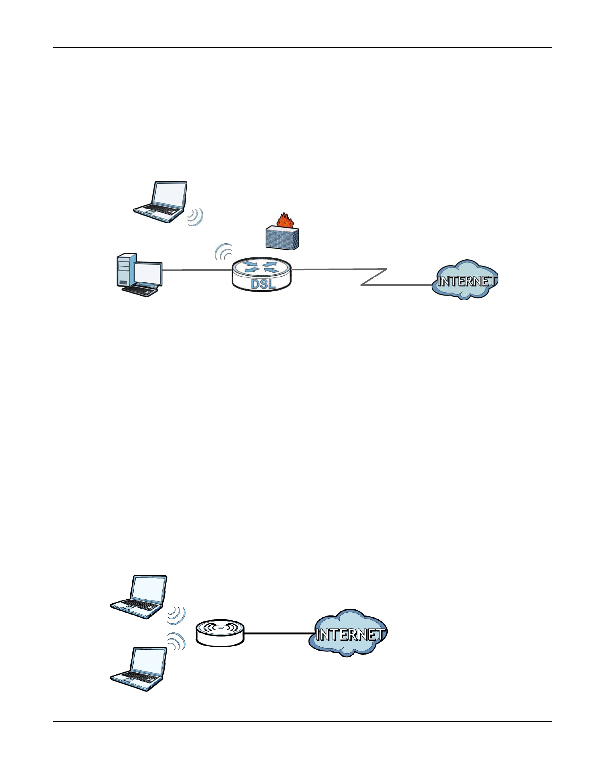
1.4.1 Internet Access
DSL
LAN WAN
Your AMG1302-T11C provides shared Internet access by connecting the DSL port to the DSL or
MODEM jack on a splitter or your telephone jack. Computers can connect to the AMG1302-T11C’s
Ethernet ports (or wirelessly).
Figure 1 AMG1302-T11C’s Router Features
You can also configure firewall and filtering feature on the AMG1302-T11C for secure Internet
access. When the firewall is on, all incoming traffic from the Internet to your network is blocked
unless it is initiated from your network. This means that probes from the outside to your network
are not allowed, but you can safely browse the Internet and download files.
Chapter 1 Introduction
Use the filtering feature to block access to specific web sites or Internet applications such as MSN or
Yahoo Messenger. You can also configure IP/MAC filtering rules for incoming or outgoing traffic.
Use QoS to efficiently manage traffic on your network by giving priority to certain types of traffic
and/or to particular computers. For example, you could make sure that the AMG1302-T11C gives
voice over Internet calls high priority, and/or limit bandwidth devoted to the boss’s excessive file
downloading.
1.4.2 Wireless Access
The ZyXEL device is a wireless Access Point (AP) for IEEE 802.11b/g/n compliant clients, such as
notebook computers or PDAs and iPads. It allows them to connect to the Internet without having to
rely on inconvenient Ethernet cables. You can set up a wireless network with WPS (WiFi Protected
Setup) or manually add a client to your wireless network.
Figure 2 Wireless Access Example
AMG1302-T11C User’s Guide
14
Page 15
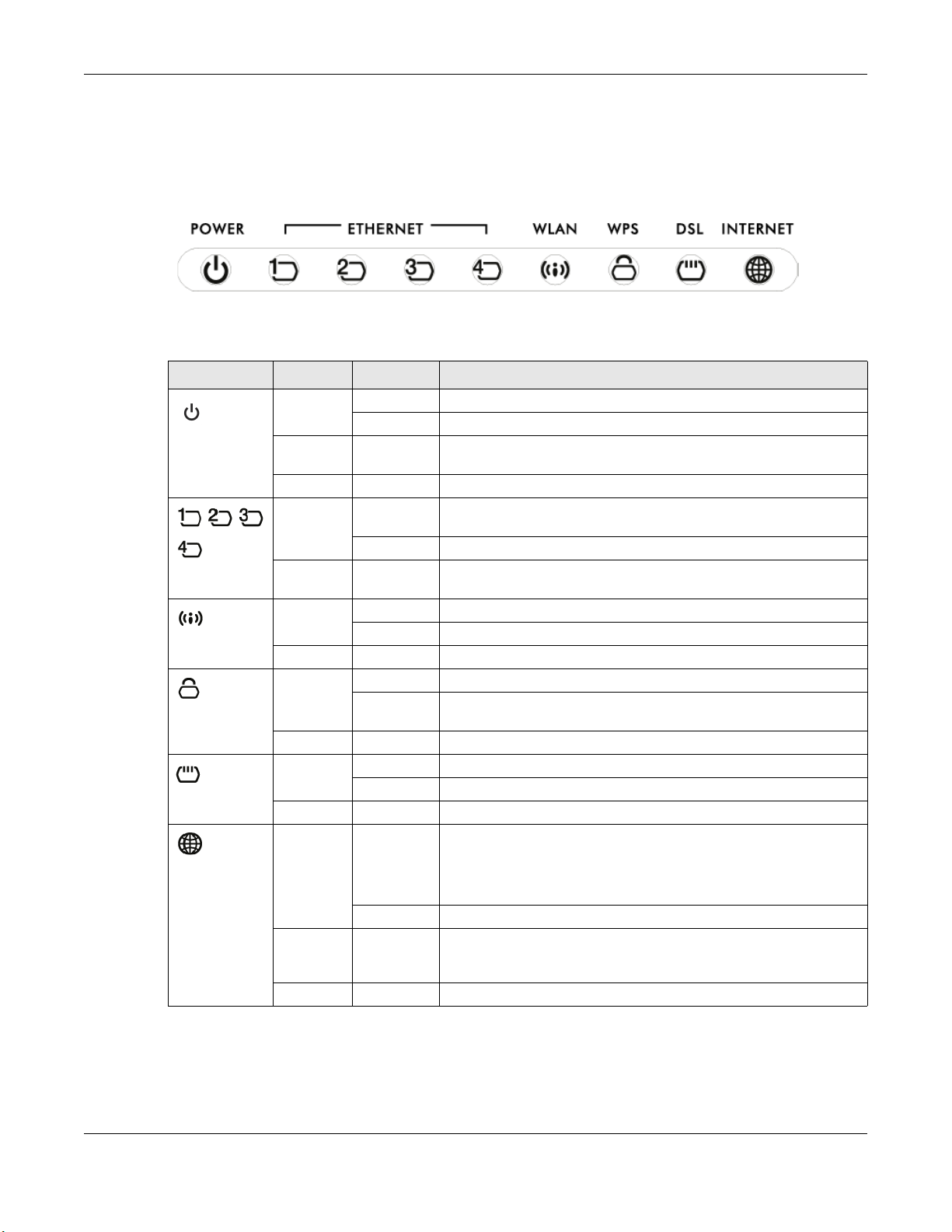
1.5 LED (Lights)
The following graphic displays the labels of the LEDs.
Figure 3 LEDs on the AMG1302-T11C
The following table describes the LEDs..
Table 1 LED Descriptions
LED COLOR STATUS DESCRIPTION
Green On The AMG1302-T11C is receiving power and ready for use.
POWER
Ethernet 1-4
WLAN
WPS
DSL
INTERNET
Red On The AMG1302-T11C detected an error while self-testing, or there
Green On The AMG1302-T11C has an Ethernet connection with a device on
Green On The wireless network is activated.
Green Blinking The AMG1302-T11C is setting up a WPS connection.
Green On The DSL line is up.
Green On The AMG1302-T11C has an IP connection but no traffic.
Red On The AMG1302-T11C attempted to make an IP connection but
Chapter 1 Introduction
Blinking The AMG1302-T11C is self-testing.
is a device malfunction.
Off The AMG1302-T11C is not receiving power.
the Local Area Network (LAN).
Blinking The AMG1302-T11C is sending/receiving data to /from the LAN.
Off The AMG1302-T11C does not have an Ethernet connection with
the LAN.
Blinking The AMG1302-T11C is communicating with other wireless clients.
Off The wireless network is not activated.
On The WPS connection is successfully made. The LED turns off after
two minuters.
Off WPS is disabled.
Blinking The AMG1302-T11C is initializing the DSL line.
Off The DSL line is down.
Your device has a WAN IP address (either static or assigned by a
DHCP server), PPP negotiation was successfully completed (if
used) and the DSL connection is up.
Blinking The AMG1302-T11C is sending or receiving IP traffic.
failed. Possible causes are no response from a DHCP server, no
PPPoE response, PPPoE authentication failed.
Off The AMG1302-T11C does not have an IP connection.
AMG1302-T11C User’s Guide
15
Page 16
Chapter 1 Introduction
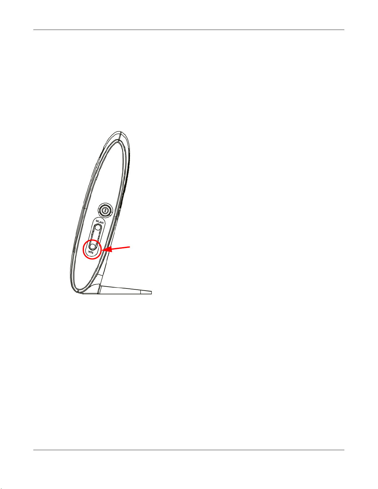
WPS
1.6 Using the WPS Button
You can also use the WPS button to quickly set up a secure wireless connection between the
AMG1302-T11C and a WPS-compatible client by adding one device at a time.
To activate WPS:
1 Make sure the POWER LED is on and not blinking.
2 Press the WPS button for 1-5 seconds and release it. See below for WPS button location.
3 Press the WPS button on another WPS-enabled device within range of the AMG1302-T11C. The
WPS LED should flash while the AMG1302-T11C sets up a WPS connection with the other wireless
device.
4 Once the connection is successfully made, the WPS LED becomes static green and turns off after
two minutes.
1.7 The RESET Button
If you forget your password or cannot access the web configurator, you will need to use the RESET
button at the back of the device to reload the factory-default configuration file. This means that you
will lose all configurations that you had previously and the user name and password will be reset to
the default.
AMG1302-T11C User’s Guide
16
Page 17

Chapter 1 Introduction
1.7.1 Using the Reset Button
1 Make sure the POWER LED is on (not blinking).
2 To set the device back to the factory default settings, press the RESET button for ten seconds or
until the POWER LED begins to blink and then release it. When the POWER LED begins to blink,
the defaults have been restored and the device restarts.
1.8 W ays to Manage the AMG1302-T11C
Use any of the following methods to manage the AMG1302-T11C.
• Web Configurator. This is recommended for everyday management of the AMG1302-T11C using a
(supported) web browser.
• FTP for firmware upgrades and configuration backup/restore.
AMG1302-T11C User’s Guide
17
Page 18
2.1 Overview
The web configurator is an HTML-based management interface that allows easy device setup and
management via Internet browser. Use Internet Explorer 8.0 and later versions, Mozilla Firefox 3
and later versions, or Safari 2.0 and later versions. The recommended screen resolution is 1024 by
768 pixels.
In order to use the web configurator, you need to allow:
• Web browser pop-up windows from your device. Web pop-up blocking is enabled by default in
Windows XP SP (Service Pack) 2.
• JavaScript (enabled by default).
• Java permissions (enabled by default).
CHAPTER 2
Introducing the Web Configurator
See Appendix D on page 259 if you need to make sure these functions are allowed in Internet
Explorer.
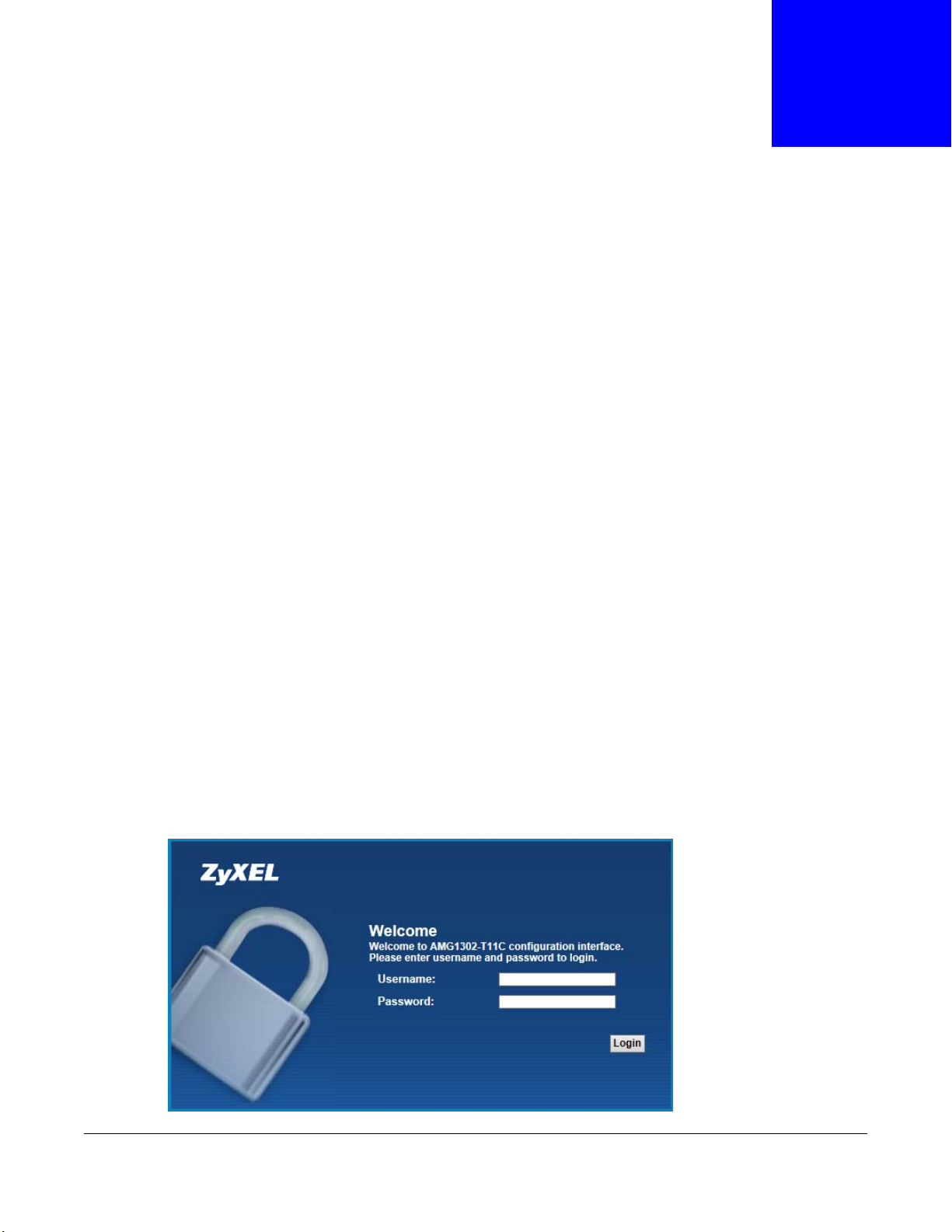
2.1.1 Accessing the Web Configurator
1 Make sure your AMG1302-T11C hardware is properly connected (refer to the Quick Start Guide).
2 Launch your web browser.
3 Type "192.168.1.1" as the URL.
4 A password screen displays. Type “admin” (default) as the username and “1234” as the password,
and click Login. If you have changed the password, enter your password and click Login.
Figure 4 Password Screen
AMG1302-T11C User’s Guide
18
Page 19
Chapter 2 Introducing the Web Configurator
Note: For security reasons, the AMG1302-T11C automatically logs you out if you do not
use the web configurator for five minutes (default). If this happens, log in again.
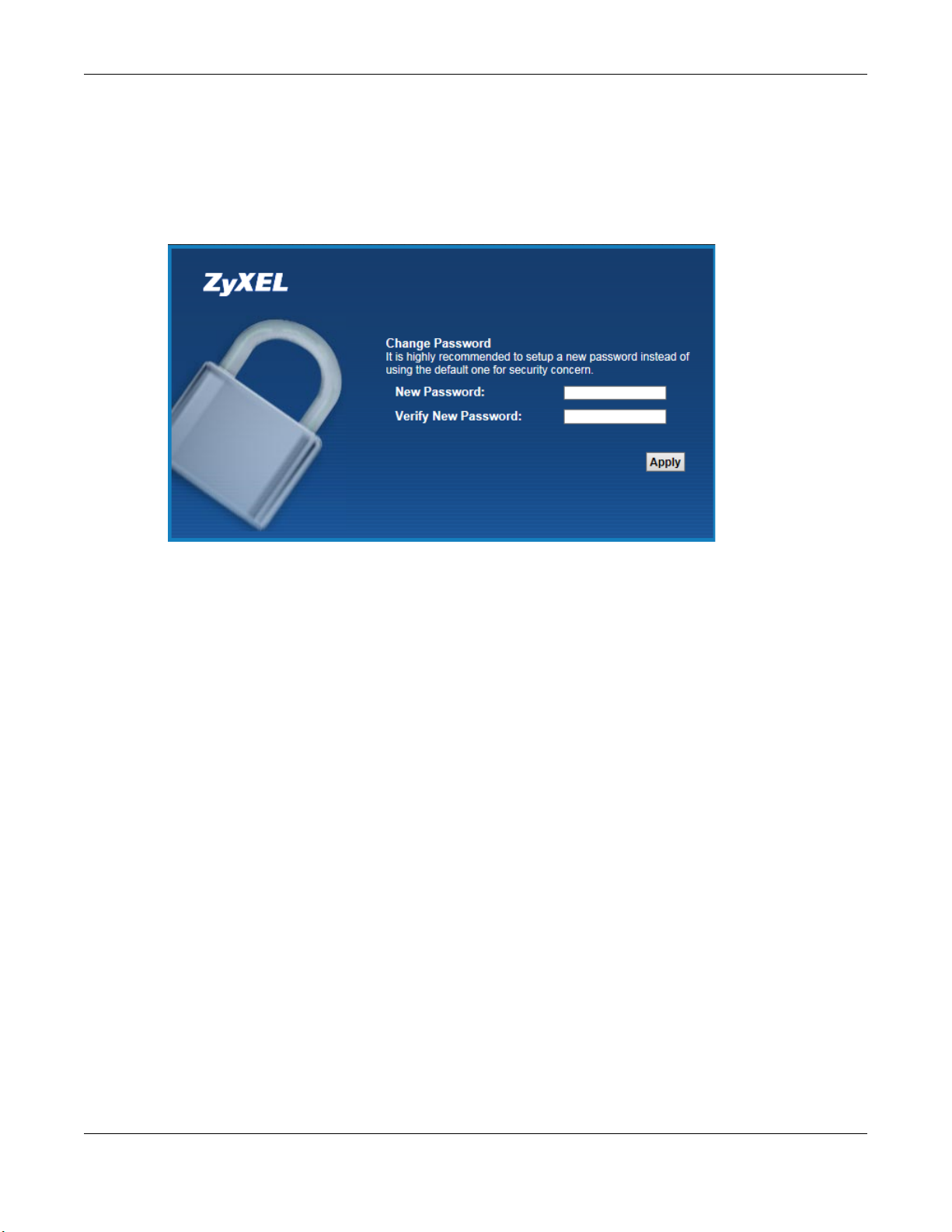
5 The following screen displays if you have not yet changed your password. It is strongly
recommended you change the default password. Enter a new password, retype it to confirm and
click Apply.
Figure 5 Change Password Screen
6 The Quick Start Wizard screen appears. You can configure basic Internet access, and wireless
settings. See Chapter 3 on page 25 for more information.
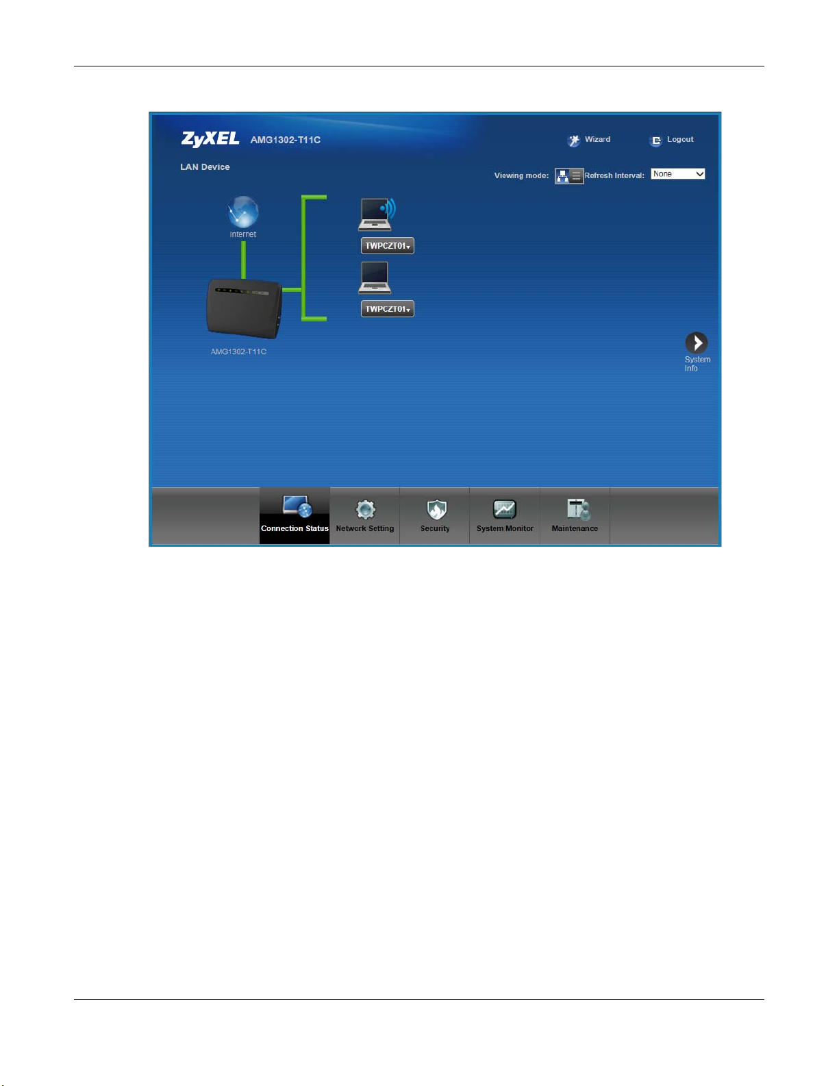
7 After you finished or closed the Quick Start Wizard screen, the Connection Status page
appears.
AMG1302-T11C User’s Guide
19
Page 20
Chapter 2 Introducing the Web Configurator
Figure 6 Connection Status
8 Click System Info to display the System Info screen, where you can view the AMG1302-T11C’s
interface and system information.
AMG1302-T11C User’s Guide
20
Page 21
Chapter 2 Introducing the Web Configurator
A
B
C
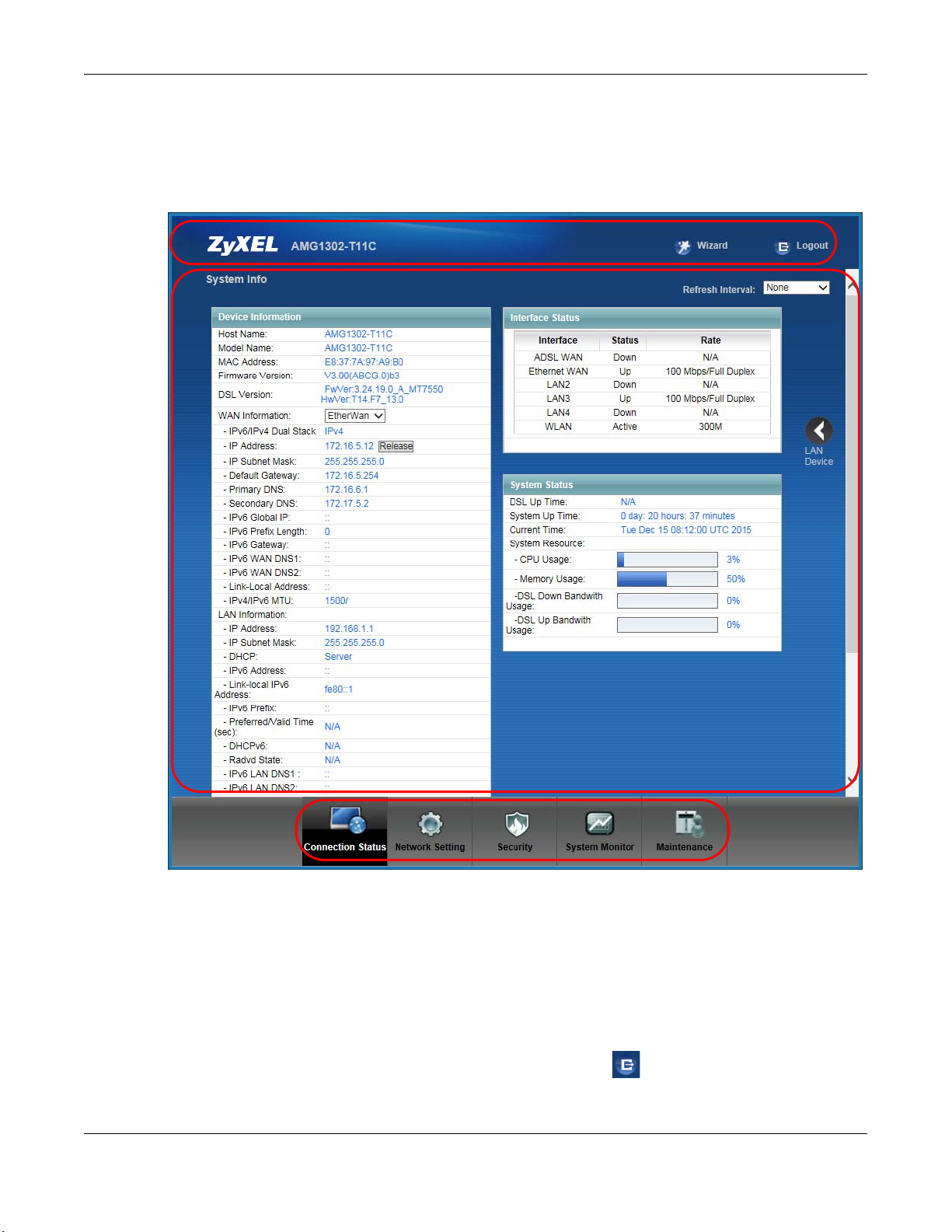
2.2 The Web Configurator Layout
Click Connection Status > System Info to show the following screen.
Figure 7 Web Configurator Layout Screen
As illustrated above, the main screen is divided into these parts:
• A - title bar
• B - main window
• C - navigation panel
2.2.1 Title Bar
The title bar shows the following icon in the upper right corner.
Click this icon to log out of the web configurator.
AMG1302-T11C User’s Guide
21
Page 22
2.2.2 Main Window
The main window displays information and configuration fields. It is discussed in the rest of this
document.
After you click System Info on the Connection Status screen, the System Info screen is
displayed. See Chapter 5 on page 62 for more information about the System Info screen.
If you click LAN Device on the System Info screen, the Connection Status screen appears. See
Chapter 5 on page 61 for more information about the Connection Status screen.
2.2.3 Navigation Panel
Use the menu items on the navigation panel to open screens to configure AMG1302-T11C features.
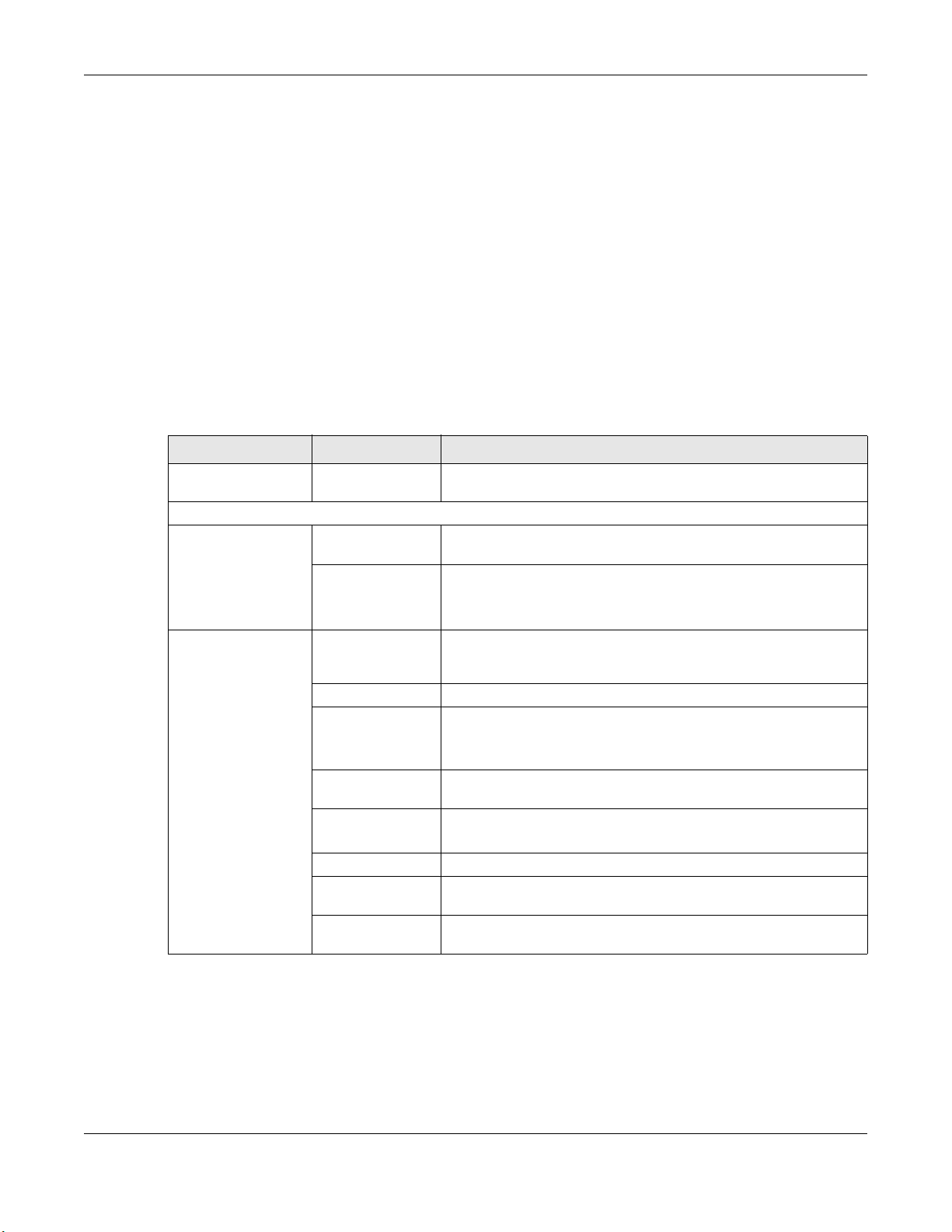
The following table describes each menu item.
Table 2 Navigation Panel Summary
LINK TAB FUNCTION
Connection Status This screen shows the network status of the AMG1302-T11C and
Network Setting
Broadband Internet
Wireless General Use this screen to turn the wireless connection on or off, specify
Chapter 2 Introducing the Web Configurator
computers/devices connected to it.
Use this screen to configure ISP parameters, WAN IP address
Connections
More Connections Use this screen to configure additional WAN connections.
More/guest AP Use this screen to configure multiple BSSs on the AMG1302-T11C.
MAC
Authentication
WPS Use this screen to use WPS (Wi-Fi Protected Setup) to establish a
WDS
WMM Use this screen to enable or disable Wi-Fi MultiMedia (WMM).
Scheduling Use this screen to configure when the AMG1302-T11C enables or
Advanced Use this screen to configure advanced wireless settings such as
assignment, DNS servers and other advanced properties.
This screen is not available when the Line Type is set to
Ethernet(ETH1) in the Internet Connection screen.
the SSID(s) and configure the wireless LAN settings and WLAN
authentication/security settings.
Use this screen to block or allow wireless traffic from wireless
devices of certain SSIDs and MAC addresses to the AMG1302T11C.
wireless connection.
Use this screen to set up Wireless Distribution System (WDS) links
to other access points.
disables the wireless LAN.
output power.
AMG1302-T11C User’s Guide
22
Page 23

Chapter 2 Introducing the Web Configurator
Table 2 Navigation Panel Summary
LINK TAB FUNCTION
Home
Networking
Static Route Static Route Use this screen to view and set up static routes on the AMG1302-
QoS General Use this screen to enable QoS and decide allowable bandwidth
NAT General Use this screen to activate/deactivate NAT.
Port Binding Port Binding Use this screen to activate/deactivate port binding, configure and
Dynamic DNS Dynamic DNS Use this screen to allow a static hostname alias for a dynamic IP
Security
Filter MAC Filter
Firewall General Use this screen to activate/deactivate the firewall.
Parental Control Parental Control
LAN Setup Use this screen to configure LAN TCP/IP settings, and other
advanced properties.
Static DHCP Use this screen to assign specific IP addresses to individual MAC
addresses.
IP Alias Use this screen to partition your LAN interface into different logical
UPnP Use this screen to enable the UPnP function.
IPv6 LAN Setup
IPv6 Static Route Use this screen to configure IPv6 static routes.
Queue Setup
Class Setup Use this screen to set up classifiers to sort traffic into different
Game List
Port Forwarding Use this screen to make your local servers visible to the outside
DMZ
ALG Use this screen to enable or disable SIP ALG.
Default Action
Rules
DoS
networks.
Use this screen to configure the IPv6 settings on the AMG1302T11C’s LAN interface.
T11C.
using QoS.
Use this screen to configure QoS queue assignment.
flows and assign priority and define actions to be performed for a
classified traffic flow.
Use this screen to give priority to traffic for specific games.
world.
Use this screen to configure a default server which receives
packets from ports that are not specified in the Port Forwarding
screen.
view port binding groups.
address.
Use this screen to configure MAC filtering rules for incoming
traffic.
Use this screen to set the default action that the firewall takes on
packets that do not match any of the firewall rules.
Use this screen to view the configured firewall rules and add, edit
or remove a firewall rule.
Use this screen to set the thresholds that the AMG1302-T11C uses
to determine when to start dropping sessions that are not fully
established (half-open sessions).
Use this screen to define time periods and days during which the
AMG1302-T11C performs parental control and/or block web sites
with the specific URL.
AMG1302-T11C User’s Guide
23
Page 24

Chapter 2 Introducing the Web Configurator
Table 2 Navigation Panel Summary
LINK TAB FUNCTION
Certificates Local Certificates Use this screen to export self-signed certificates or certification
requests and import the AMG1302-T11C’s CA-signed certificates.
Trusted CA Use this screen to save CA certificates to the AMG1302-T11C.
System Monitor
Log Log
Traffic Status WAN Use this screen to view the status of all network traffic going
LAN Use this screen to view the status of all network traffic going
NAT Use this screen to view the status of NAT sessions on the
Maintenance
Users Account Users Account Use this screen to configure the passwords your user accounts.
TR-069 Client TR-069 Client
System System Use this screen to configure management inactivity time-out
Time Setting Time Setting Use this screen to change your AMG1302-T11C’s time and date.
Log Setting Log Setting Use this screen to select which logs and/or immediate alerts your
Firmware
Upgrade
Backup/Restore Backup/Restore Use this screen to backup and restore your device’s configuration
Reboot Reboot Use this screen to reboot the AMG1302-T11C without turning the
Remote MGMT Remote MGMT Use this screen to enable specific traffic directions for specific
Diagnostic Ping Use this screen to test the connections to other devices.
Firmware Upgrade Use this screen to upload firmware to your device.
SNMP Use this screen to configure SNMP (Simple Network Management
Trust Dom a in Use this screen to view and manage a list of public IP addresses
DSL Line Use this screen to identify problems with the DSL connection.
Use this screen to view the logs for the level that you selected.
You can export or e-mail the logs.
through the WAN port of the AMG1302-T11C.
through the LAN ports of the AMG1302-T11C.
AMG1302-T11C.
Use this screen to configure the AMG1302-T11C to be managed by
an Auto Configuration Server (ACS).
setting.
device is to record. You can also set it to e-mail the logs to you.
(settings) or reset the factory default settings.
power off.
network service.
Protocol) settings.
which are allowed to access the AMG1302-T11C through a
configured service.
AMG1302-T11C User’s Guide
24
Page 25
3.1 Overview
Use the wizard setup screens to configure your system for Internet access with the information
given to you by your ISP.
Note: See the advanced menu chapters for background information on these fields.
3.2 Quick Start Setup
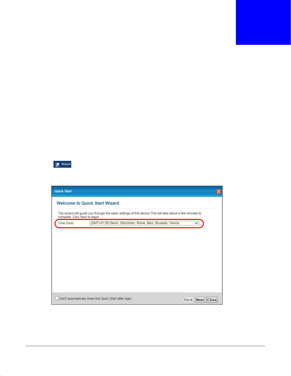
1 The Quick Start Wizard appears automatically after login. Or you can click the Wizard icon
( ) in the top right corner of the web configurator to open the quick start screens.
CHAPTER 3
Quick Start Wizard
2 Select the time zone of your location. Click Next.
Figure 8 Wizard Welcome
3 Enter your Internet access information in the wizard screen exactly as your service provider gave it
to you. Leave the defaults in any fields for which you were not given information. The screen and
fields to enter may vary depending on your current connection type.
4 Configure the field and click Next to continue.
AMG1302-T11C User’s Guide
25
Page 26
Chapter 3 Quick Start Wizard
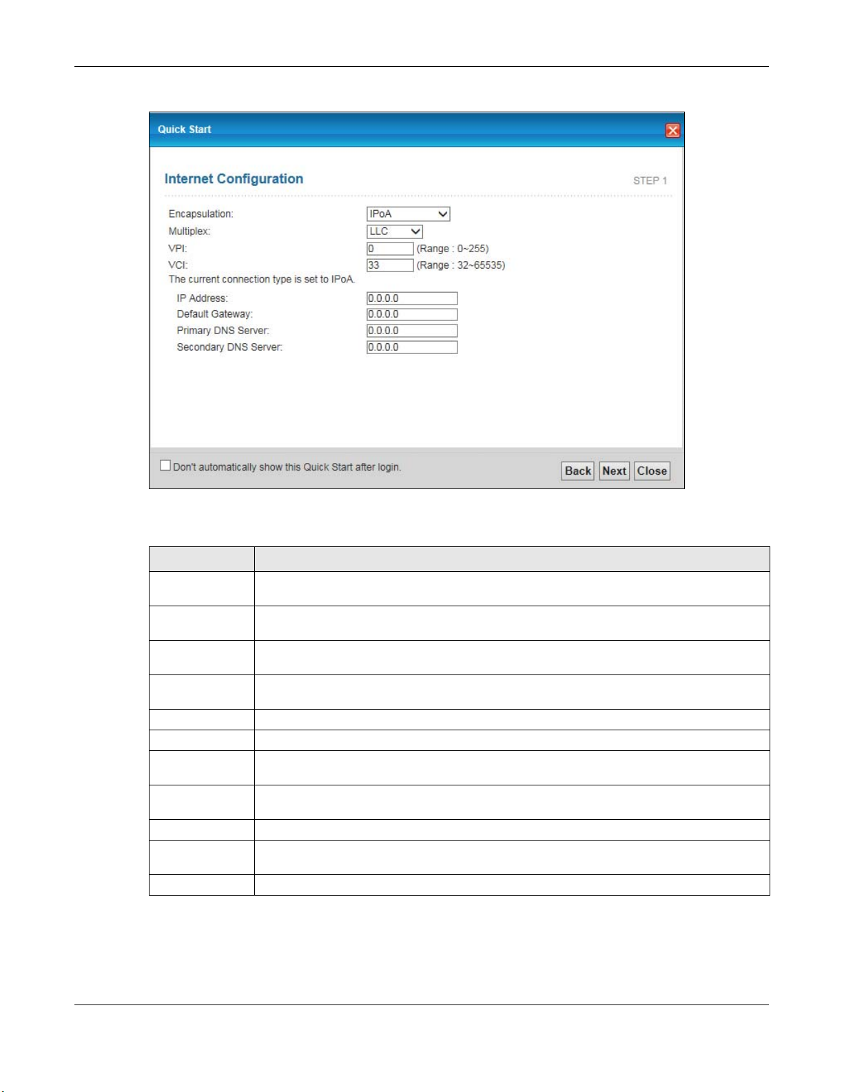
Figure 9 Internet Access Wizard Setup: IPoA Configuration
The following table describes the fields in this screen.
Table 3 Internet Access Wizard Setup: IPoA Configuration
LABEL DESCRIPTION
Encapsulation Select the encapsulation type your ISP uses from the Encapsulation drop-down list box:
IPoA, ENET ENCAP, PPPoA, or PPPoE.
Multiplex Select the multiplexing method used by your ISP from the Multiplex drop-down list box
either VC-based or LLC-based.
VPI Enter the Virtual Path Identifier (VPI) assigned to you. This field may already be
VCI Enter the Virtual Channel Identifier (VCI) assigned to you. This field may already be
IP Address Enter the IP address of the AMG1302-T11C.
Default Gateway Enter the default gateway of the ZyXEL Device.
Primary DNS
Server
Secondary DNS
Server
Back Click this to return to the previous screen without saving.
Next Click this to continue to the next wizard screen. The next wizard screen you see depends
Close Click this to close the wizard screen without saving.
configured.
configured.
Enter the primary DNS server IP address for the AMG1302-T11C.
Enter the secondary DNS server IP address for the AMG1302-T11C.
on what protocol you chose above.
Note: Virtual Path Identifier (VPI) and Virtual Channel Identifier (VCI) define a virtual
circuit.
AMG1302-T11C User’s Guide
26
Page 27
Chapter 3 Quick Start Wizard
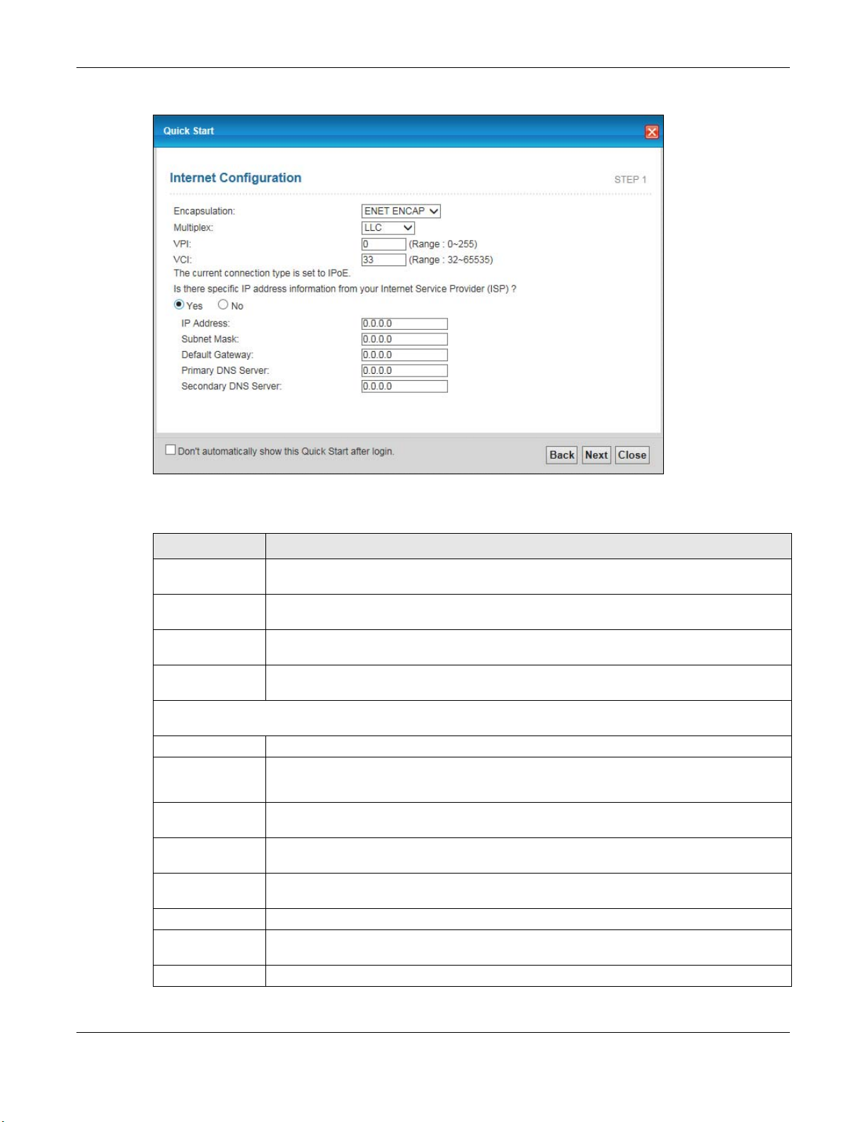
Figure 10 Internet Connection with ENET ENCAP
The following table describes the fields in this screen.
Table 4 Internet Connection with ENET ENCAP
LABEL DESCRIPTION
Encapsulation Select the encapsulation type your ISP uses from the Encapsulation drop-down list box:
IPoA, ENET ENCAP, PPPoA, or PPPoE.
Multiplex Select the multiplexing method used by your ISP from the Multiplex drop-down list box
VPI Enter the Virtual Path Identifier (VPI) assigned to you. This field may already be
VCI Enter the Virtual Channel Identifier (VCI) assigned to you. This field may already be
Select Yes to enter specific IP information from your Internet service provider.
either VC-based or LLC-based.
configured.
configured.
Enter your Internet
access information exactly as your service provider gave it to you.
IP Address Enter the IP address of the AMG1302-T11C.
Subnet Mask Enter the subnet mask in dotted decimal notation.
Refer to the appendix to calculate a subnet mask if you are implementing subnetting.
Default Gateway You must specify a gateway IP address (supplied by your ISP) when you use ENET ENCAP
Primary DNS
Server
Secondary DNS
Server
Back Click this to return to the previous screen without saving.
Next Click this to continue to the next wizard screen. The next wizard screen you see depends
Close Click this to close the wizard screen without saving.
in the Encapsulation field in the previous screen.
Enter the primary DNS server IP address for the AMG1302-T11C.
Enter the secondary DNS server IP address for the AMG1302-T11C.
on what protocol you chose above.
AMG1302-T11C User’s Guide
27
Page 28
Chapter 3 Quick Start Wizard
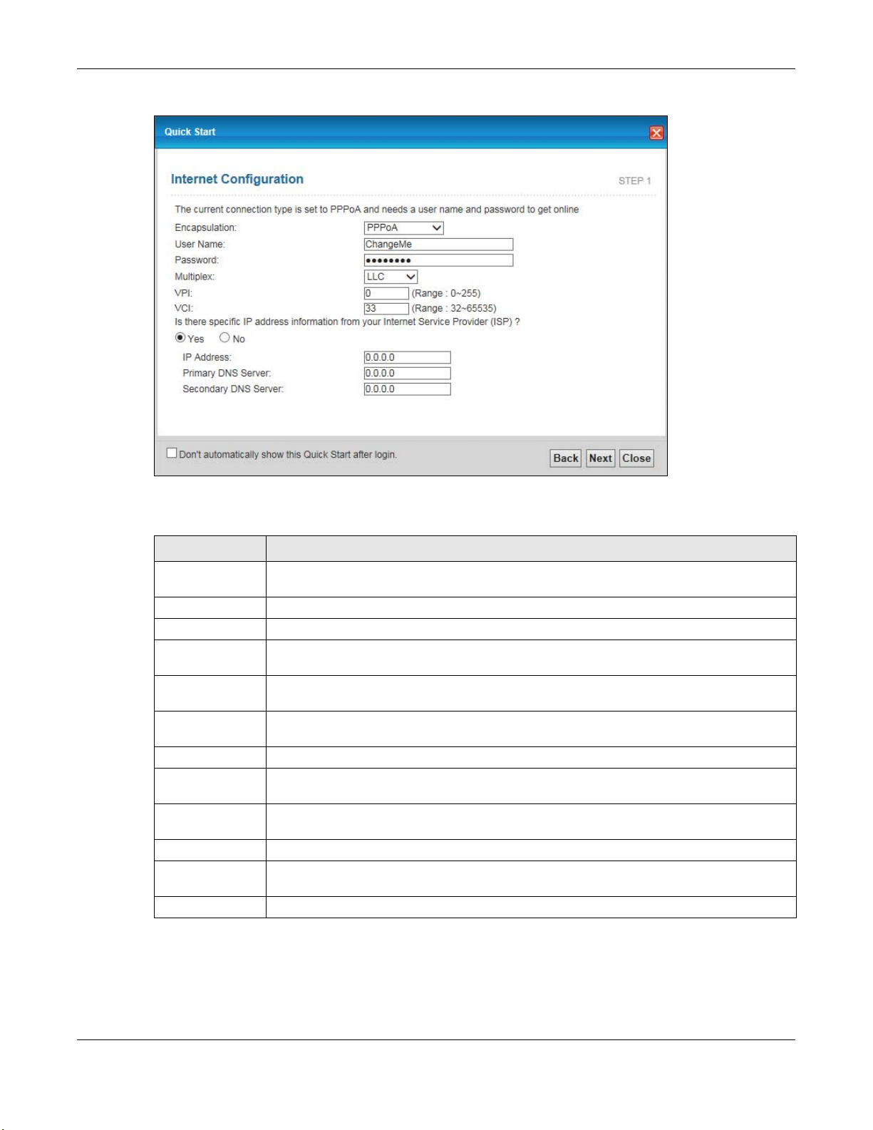
Figure 11 Internet Connection with PPPoA
The following table describes the fields in this screen.
Table 5 Internet Connection with PPPoA
LABEL DESCRIPTION
Encapsulation Select the encapsulation type your ISP uses from the Encapsulation drop-down list box:
IPoA, ENET ENCAP, PPPoA, or PPPoE.
User Name Enter the login name that your ISP gives you.
Password Enter the password associated with the user name above.
Multiplex Select the multiplexing method used by your ISP from the Multiplex drop-down list box
VPI Enter the Virtual Path Identifier (VPI) assigned to you. This field may already be
VCI Enter the Virtual Channel Identifier (VCI) assigned to you. This field may already be
IP Address Enter the IP address of the AMG1302-T11C.
Primary DNS
Server
Secondary DNS
Server
Back Click this to return to the previous screen without saving.
Next Click this to continue to the next wizard screen. The next wizard screen you see depends
Close Click this to close the wizard screen without saving.
either VC-based or LLC-based.
configured.
configured.
Enter the primary DNS server IP address for the AMG1302-T11C.
Enter the secondary DNS server IP address for the AMG1302-T11C.
on what protocol you chose above.
AMG1302-T11C User’s Guide
28
Page 29
Chapter 3 Quick Start Wizard
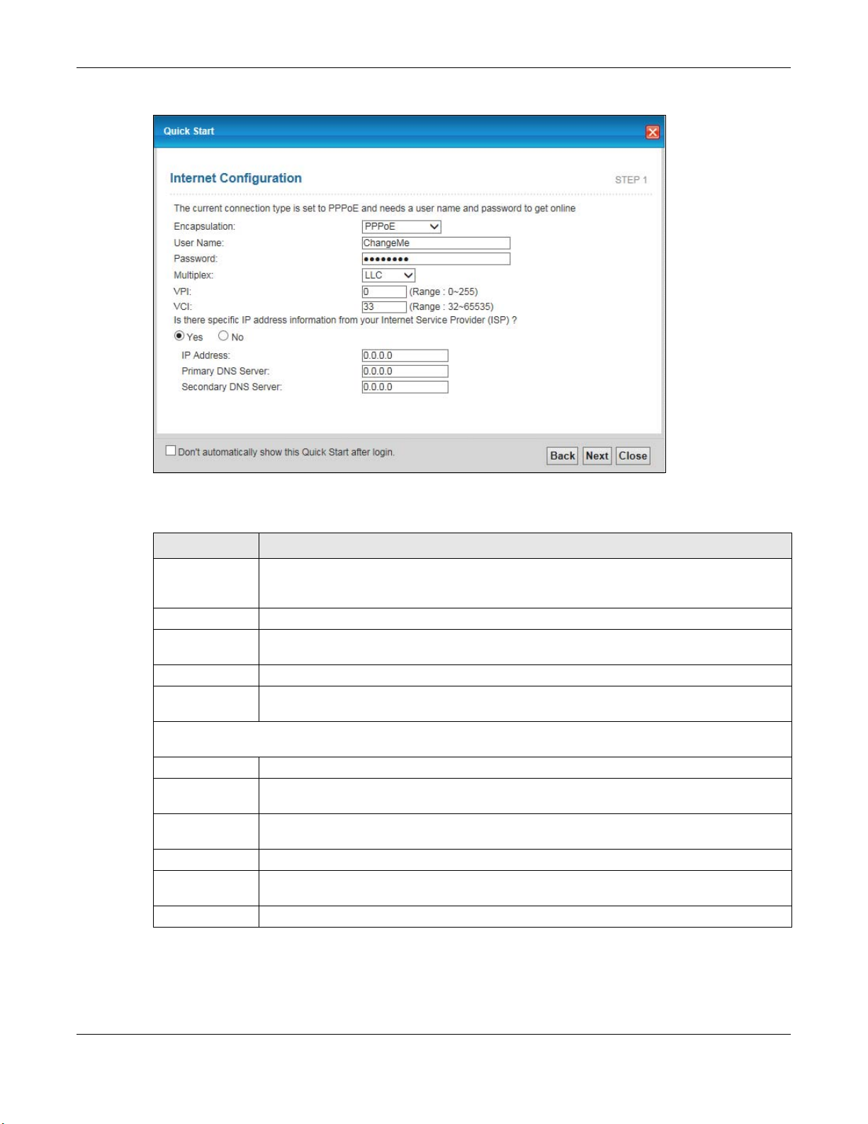
Figure 12 Internet Connection with PPPoE
The following table describes the fields in this screen.
Table 6 Internet Connection with PPPoE
LABEL DESCRIPTION
User Name Enter the user name exactly as your ISP assigned. If assigned a name in the form
user@domain where domain identifies a service name, then enter both components exactly
as given.
Password Enter the password associated with the user name above.
Multiplex Select the multiplexing method used by your ISP from the Multiplex drop-down list box
either VC-based or LLC-based.
VPI Enter the Virtual Path Identifier (VPI) assigned to you. This field may already be configured.
VCI Enter the Virtual Channel Identifier (VCI) assigned to you. This field may already be
Select Yes to enter specific IP information from your Internet service provider. Enter your Internet access
information exactly as your service provider gave it to you.
IP Address Enter the IP address of the AMG1302-T11C.
Primary DNS
Server
Secondary DNS
Server
Back Click this to return to the previous screen without saving.
Next Click this to continue to the next wizard screen. The next wizard screen you see depends on
Close Click this to close the wizard screen without saving.
configured.
Enter the primary DNS server IP address for the AMG1302-T11C.
Enter the secondary DNS server IP address for the AMG1302-T11C.
what protocol you chose above.
• If the user name and/or password you entered for PPPoE or PPPoA connection are not correct,
you are prompted to enter the correct information.
• If the Internet connection fails, check to see if your account is activated.
AMG1302-T11C User’s Guide
29
Page 30
Chapter 3 Quick Start Wizard
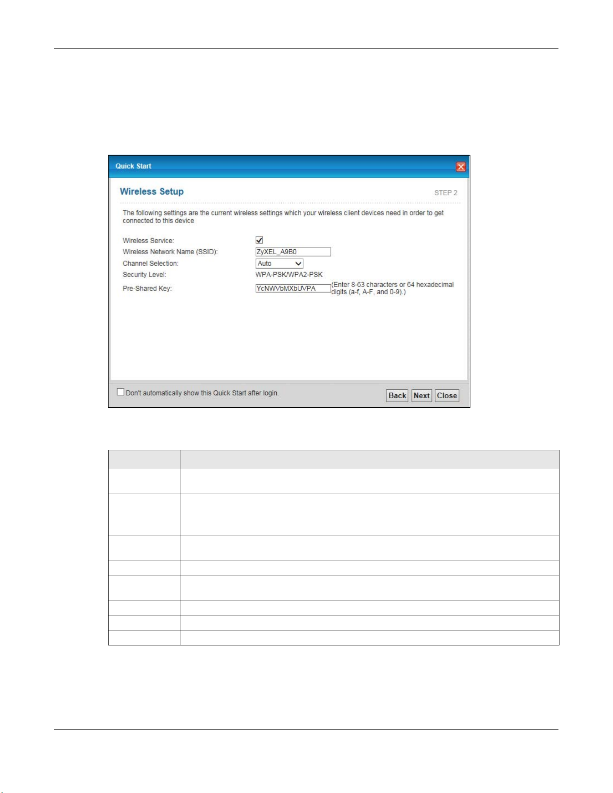
After you configure the Internet access information, use the following screen to set up your wireless
LAN.
5 Check the Wireless Service box to enable wireless connection on the ZyXEL device.
6 Configure your wireless settings in this screen. Click Next.
Figure 13 Wireless Setup
The following table describes the labels in this screen.
Table 7 Wireless Setup
LABEL DESCRIPTION
Wireless
Service
Wireless
Network
Name(SSID)
Channel
Selection
Security Level Displays the security setting. To mofidy, see Section 7.2 on page 88.
Pre-Shared Key Enter a set of characters (8 to 63 characters or 64 hexadecimal digits [a-f, A-F, and 0-9]) for
Back Click this to return to the previous screen without saving.
Next Click this to continue to the next wizard screen.
Close Click this to close the wizard screen without saving.
Click this to enable or disable the wireless service on the ZyXEL device.
Enter a descriptive name (up to 32 printable 7-bit ASCII characters) for the wireless LAN.
If you change this field on the AMG1302-T11C, make sure all wireless stations use the same
SSID in order to access the network.
The range of radio frequencies used by IEEE 802.11b/g wireless devices is called a channel.
Select a channel ID that is not already in use by a neighboring device.
the shared security key.
Note: The wireless stations and AMG1302-T11C must use the same SSID and channel ID
for wireless communication.
7 The configuration settings are saved and applied. Click Close to complete the setup.
AMG1302-T11C User’s Guide
30
Page 31

Figure 14 Results Summary
Chapter 3 Quick Start Wizard
8 Launch your web browser and navigate to www.zyxel.com. Internet access is just the beginning.
Refer to the rest of this guide for more detailed information on the complete range of AMG1302T11C features. If you cannot access the Internet, open the web configurator again to confirm that
the Internet settings you configured in the wizard setup are correct.
AMG1302-T11C User’s Guide
31
Page 32

4.1 Overview
This chapter shows you how to use the AMG1302-T11C’s various features.
• Setting Up Your DSL Connection, see page 32
• IPv6 Address Configuration, see page 35
• Setting Up a Secure Wireless Network, see page 35
• Configuring the MAC Address Filter for Restricting Wireless Internet Access, see page 43
• Setting Up NAT Forwarding for a Game Server, see page 44
• Configuring Firewall Rules to Allow a Specified Service, see page 46
• Configuring Static Route for Routing to Another Network, see page 49
• Port Binding Configuration, see page 51
• Configuring QoS to Prioritize Traffic, see page 55
• Access the AMG1302-T11C from the Internet Using DDNS, see page 58
CHAPTER 4
Tutorials
4.2 Setting Up Your DSL Connection
This tutorial shows you how to set up your Internet connection using the web configurator.
If you connect to the Internet through a DSL connection, use the information from your Internet
Service Provider (ISP) to configure the AMG1302-T11C. Do the following steps:
1 Connect the AMG1302-T11C properly. Refer to the Quick Start Guide for details on the AMG1302-
T11C’s hardware connection.
2 Connect one end of a DSL cable to the DSL port of your AMG1302-T11C. The other end should be
connected to the DSL port in your house or a DSL router/modem provided by your ISP.
3 Connect one end of Ethernet cable to an Ethernet port on the AMG1302-T11C and the other end to
a computer that you will use to access the web configuration.
4 Connect the AMG1302-T11C to a power source, turn it on and wait for the POWER LED to become
a steady green.
AMG1302-T11C User’s Guide
32
Page 33

Chapter 4 Tutorials
Account Configuration
For this example, the interface type is ADSL and the connection has the following information.
General
Mode Router
Encapsulation PPPoE
User Name 1234@DSL-Ex.com
Password ABCDEF!
Service Name My DSL
Multiplex LLC
IPv6/IPv4 Dual
Stack
PPP
Authentication
VPI 0
VCI 33
Others IP Address: Obtain IP Address Automatically
Enabled
Auto
DNS Server: Obtained From ISP
IPv6 Address: Obtain IPv6 Address Automatically
DHCP IPv6: DHCP
DHCP PD: Enable
WAN Identifier Type: EUI64
AMG1302-T11C User’s Guide
33
Page 34

Chapter 4 Tutorials
Go to Network Setting > Broadband, enter or select these values and click Apply.
This completes your DSL WAN connection setting.
AMG1302-T11C User’s Guide
34
Page 35

Chapter 4 Tutorials
IPv6
IPv6
IPv6
4.3 IPv6 Address Configuration
If the ISP’s network supports IPv6, the ISP may assign an IPv6 address to the AMG1302-T11C
automatically.
In the Network Setting > Broadband screen’s IPv6 Address configuration section, select
Obtain an IP Address Automatically. In the DHCP IPv6 field select DHCP to obtain an IPv6
address from a DHCPv6 server. In the DHCP PD field select Enable to have the AMG1302-T11C
pass the WAN prefix to LAN hosts. The LAN hosts can then use the prefix to generate their IPv6
addresses.
4.4 Setting Up a Secure Wireless Network
Thomas wants to set up a wireless network so that he can use his notebook to access the Internet.
In this wireless network, the AMG1302-T11C serves as an access point (AP), and the notebook is
the wireless client. The wireless client can access the Internet through the AP.
Thomas has to configure the wireless network settings on the AMG1302-T11C. Then he can set up
a wireless network using WPS (Section 4.4.2 on page 37) or manual configuration (Section 4.4.3 on
page 41).
AMG1302-T11C User’s Guide
35
Page 36

Chapter 4 Tutorials
EXAM
PLE
4.4.1 Configuring the Wireless Network Settings
This example uses the following parameters to set up a wireless network. In the client, choose the
AP with the SSID configured here. When prompted for a key, use the Pre-Shared Key configured
here.
SSID SecureWirelessNetwork
Security Mode WPA2-PSK
Pre-Shared Key DoNotStealMyWirelessNetwork
802.11 Mode 802.11b+g+n
1 Click Network Setting > Wireless to open the General screen. Configure the screen using the
provided parameters (see page 36). Click Apply.
2 Click Network Setting > Wireless > Advanced and make sure 802.11b+g+n is selected in the
802.11 Mode field. Click Apply.
AMG1302-T11C User’s Guide
36
Page 37

Thomas can now use the WPS feature to establish a wireless connection between his notebook and
the AMG1302-T11C (see Section 4.4.2 on page 37). He can also use the notebook’s wireless client
to search for the AMG1302-T11C (see Section 4.4.3 on page 41).
4.4.2 Using WPS
This section shows you how to set up a wireless network using WPS. WPS is a way to automatically
set up a secure wireless network connection between an AP and a notebook. Limitations of using
WPS are that is must be done two devices at a time and within two minutes. It uses the AMG1302T11C as the AP and ZyXEL NWD210N as the wireless client which connects to the notebook.
Chapter 4 Tutorials
Note: The wireless client must be a WPS-aware device (for example, a WPS USB adapter
or PCMCIA card).
There are two WPS methods to set up the wireless client settings:
• Push Button Configuration (PBC) - simply press a button. This is the easier of the two
methods.
• PIN Configuration - configure a Personal Identification Number (PIN) on the AMG1302-T11C. A
wireless client must also use the same PIN in order to download the wireless network settings
from the AMG1302-T11C.
Push Button Configuration (PBC)
1 Make sure that your AMG1302-T11C is turned on and your notebook is within the cover range of the
wireless signal.
2 Make sure that you have installed the wireless client driver and utility in your notebook.
3 Make sure wireless LAN is enabled and the wireless security mode is set to WPA-PSK2 or No
Security in the Network Setting > Wireless > General screen.
4 In the wireless client utility, go to the WPS setting page. Enable WPS and press the WPS button
(Start or WPS button).
5 Push and hold the WPS button on the AMG1302-T11C for 1-2 seconds. Alternatively, you may log
into AMG1302-T11C’s web configuration, enable WPS and click the WPS button in the Network
Setting > Wireless > WPS screen.
AMG1302-T11C User’s Guide
37
Page 38

Chapter 4 Tutorials
Note: It doesn’t matter which button (on the client or the AMG1302-T11C) is pressed
first. You must press the second button within two minutes of pressing the first
one.
The AMG1302-T11C sends the proper configuration settings to the wireless client. This may take up
to two minutes. The wireless client is then able to communicate with the AMG1302-T11C securely.
The following figure shows you an example of how to set up a wireless network and its security by
pressing a button on both AMG1302-T11C and wireless client.
AMG1302-T11C User’s Guide
38
Page 39

Example WPS Process: PBC Method
Wireless Client
The Device
SECURITY INFO
COMMUNICATION
WITHIN 2 MINUTES
Press and hold for
5 seconds
Chapter 4 Tutorials
PIN Configuration
When you use the PIN configuration method, you need to use both the AMG1302-T11C’s web config
ur at or and the wireless client’s utility.
1 Launch your wireless client’s configuration utility. Go to the WPS settings and select the PIN method
to get a PIN number.
2 Enter the PIN number in the PIN section in the Network Setting > Wireless > WPS screen on
the AMG1302-T11C.
AMG1302-T11C User’s Guide
39
Page 40

Chapter 4 Tutorials
3 Click the Start and Register buttons (or the button next to the PIN field) on both the wireless
client utility screen and the AMG1302-T11C’s WPS screen within two minutes.
The AMG1302-T11C authenticates the wireless client and sends the proper configuration settings to
the wireless client. This may take up to two minutes. The wireless client is then able to
communicate with the AMG1302-T11C securely.
The following figure shows you how to set up a wireless network and its security on a AMG1302T11C and a wireless client by using PIN method.
AMG1302-T11C User’s Guide
40
Page 41

Example WPS Process: PIN Method
Authentication by PIN
SECURITY INFO
WITHIN 2 MINUTES
Wireless Client
The Device
COMMUNICATION
Chapter 4 Tutorials
4.4.3 Connecting Wirelessly to your AMG1302-T11C
1 Right-click the wireless adapter icon which appears in the bottom right of your computer monitor.
This section describes how to connect wirelessly to your AMG1302-T11C. The connection procedure
is shown here using Windows XP as an example.
Click View Available Wireless Networks.
AMG1302-T11C User’s Guide
41
Page 42

Chapter 4 Tutorials
A
Tutorial: Status
2 Select the AMG1302-T11C’s SSID name and click Connect (A). The SSID “SecureWirelessNetwork”
is given here as an example.
Tutorial: Status
3 You are prompted to enter a password. Enter it and click Connect.
Tutorial: Status
4 You may have to wait several minutes while your computer connects to the wireless network.
5 You should now be securely connected wirelessly to the AMG1302-T11C.
Tutorial: Status
AMG1302-T11C User’s Guide
42
Page 43

Chapter 4 Tutorials
Thomas
Josephine
Congratulations! Your computer is now ready to connect to the Internet wirelessly through your
AMG1302-T11C.
Note: If you cannot connect wirelessly to the AMG1302-T11C, check you have selected
the correct SSID and entered the correct security key. If that does not work,
ensure your wireless network adapter is enabled by clicking on the wireless adapter
icon and clicking Enable.
4.5 Configuring the MAC Address Filter for Restricting Wireless Internet Access
Thomas noticed that his daughter Josephine spends too much time surfing the web and
downloading media files. He decided to prevent Josephine from accessing the Internet so that she
can concentrate on preparing for her final exams.
Josephine’s computer connects wirelessly to the Internet through the AMG1302-T11C. Thomas can
deny access to the wireless network using the MAC address of Josephine’s computer.
1 Check the MAC address (physical address) of the wireless card on Josephine’s computer using the
“ipconfig /all” command in a Command Prompt.
AMG1302-T11C User’s Guide
43
Page 44

Chapter 4 Tutorials
EXAMPLE
C:\>ipconfig /all
Ethernet adapter Wireless Network Connection:
Media State . . . . . . . . . . . : Media connected
Description . . . . . . . . . . . : Wireless USB Adapter
Physical Address. . . . . . . . . : 00-1E-52-C3-5C-1B
---------------------------SNAP!--------------------------------
2 Click Network Setting > Wireless > MAC Authentication. Select the wireless network in the
SSID field and then Deny in the MAC Restrict Mode field.
3 Enter the MAC address that you want to deny. Click OK.
Josephine will no longer be able to access the Internet wirelessly through the AMG1302-T11C.
4.6 Setting Up NAT Forwarding for a Game Server
Thomas manages a Doom server on a computer behind the AMG1302-T11C. In order for players on
the Internet (like A in the figure below) coming through the default WAN connection (PVC0) to
communicate with the Doom server, Thomas can use port forwarding.
AMG1302-T11C User’s Guide
44
Page 45

Tutorial: NAT Port Forwarding Setup
D=192.168.1.34
WAN
LAN
port 666
A
4.6.1 Port Forwarding
Thomas needs to configure the port settings and IP address on the AMG1302-T11C. Traffic should
be forwarded to port 666 of the Doom server computer which has an IP address of 192.168.1.34.
Thomas may set up the port settings by configuring the port settings for the Doom server computer
(see Section 11.3 on page 150 for more information).
Chapter 4 Tutorials
1 Activate NAT in the Network Setting > NAT > General screen. Click Apply.
2 Click Network Setting > NAT > Port Forwarding. Select PVC0 as the WAN interface and click
Add new rule.
3 Configure the screen with the following values:
Service Name Select User Define.
Start/End Ports Enter 666 as the Start and End port.
Server IP Address Enter the IP address of the Doom server (192.168.1.34 for this example).
The screen should look as follows. Click Apply.
AMG1302-T11C User’s Guide
45
Page 46

Chapter 4 Tutorials
E
XAMPLE
EXAM
PLE
4 The port forwarding settings you configured appear in the table. The AMG1302-T11C forwards port
666 traffic to the computer with IP address 192.168.1.34.
Players on the Internet then can have access to Thomas’ Doom server.
4.7 Configuring Firewall Rules to Allow a Specified Service
By default the firewall will block traffic originating from the WAN (1). However, if you are running a
server or other service, you may need to allow access from the WAN (2). The following tutorial will
show how to allow traffic from WAN to LAN if it matches a specified port number.
AMG1302-T11C User’s Guide
46
Page 47

Chapter 4 Tutorials
WAN
LAN
1
2
A
Tutorial: NAT Port Forwarding Setup
1 Click Security > Firewall and select Custom. Click Apply to save your settings.
Tutorial: Advanced > QoS
2 Click the Rules tab. In the Packet Direction field select WAN to LAN and click Add.
Tutorial: Advanced > QoS > Queue Setup
3 The Add New Firewall Rule screen will appear. Click the Edit Customized Services button to
access the following screen. Click Add and configure the following settings. In this tutorial, a
hypothetical port 123 is allowed. Click OK.
Service Name My_Service
Service Type TCP
Port Number 123
AMG1302-T11C User’s Guide
47
Page 48

Chapter 4 Tutorials
Tutorial: Advanced > QoS > Queue Setup
4 In the Add New Firewall Rule screen, select Active. In the Available Services field, select the
service you configured, My_Service. Click OK.
Tutorial: Advanced > QoS > Queue Setup
AMG1302-T11C User’s Guide
48
Page 49

Chapter 4 Tutorials
N2
B
N1
A
R
5 The firewall rule you configured appears in the table. The AMG1302-T11C allows traffic from the
WAN to LAN if it matches port 123.
4.8 Configuring Static Route for Routing to Another Network
In order to extend your Intranet and control traffic flowing directions, you may connect a router to
the AMG1302-T11C’s LAN. The router may be used to separate two department networks. This
tutorial shows how to configure a static routing rule for two network routings.
In the following figure, router R is connected to the AMG1302-T11C’s LAN. R connects to two
networks, N1 (192.168.1.x/24) and N2 (192.168.10.x/24). If you want to send traffic from
computer A (in N1 network) to computer B (in N2 network), the traffic is sent to the AMG1302T11C’s WAN default gateway by default. In this case, B will never receive the traffic.
You need to specify a static routing rule on the AMG1302-T11C to specify R as the router in charge
of forwarding traffic to N2. In this case, the AMG1302-T11C routes traffic from A to R and then R
routes the traffic to B.
AMG1302-T11C User’s Guide
49
Page 50

Chapter 4 Tutorials
N2
B
N1
A
R
This tutorial uses the following example IP settings:
Table 8 IP Settings in this Tutorial
DEVICE / COMPUTER IP ADDRESS
The AMG1302-T11C’s WAN 172.16.1.1
The AMG1302-T11C’s LAN 192.168.1.1
A 192.168.1.34
R’s N1 192.168.1.253
R’s N2 192.168.10.2
B 192.168.10.33
To configure a static route to route traffic from N1 to N2:
1 Log into the AMG1302-T11C’s Web Configurator.
2 Click Network Setting > Static Route.
3 Click Edit on a new rule in the Static Route screen.
4 Configure the Static Route Setup screen using the following settings:
4a Type 192.168.10.0 and subnet mask 255.255.255.0 for the destination, N2.
4b Select Enable and type 192.168.1.253 (R’s N1 address) in the Gateway IP Address field.
4c Enter 1 in the Metric field.
AMG1302-T11C User’s Guide
50
Page 51

Chapter 4 Tutorials
4d Click OK.
Now B should be able to receive traffic from A. You may need to additionally configure B’s firewall
settings to allow specific traffic to pass through.
4.9 Port Binding Configuration
This tutorial shows you how to configure port binding for WAN connections with different ATM QoS
settings for different types of traffic. The port binding feature is used to group each WAN connection
with specific LAN ports and WLANs. In this example ATM QoS settings are configured for a WAN PVC
for time sensitive Media-On-Demand (MOD) traffic. ATM QoS settings are also configured for
another WAN PVC for non-time sensitive data traffic.
4.9.1 Configuring ATM QoS for Multiple WAN Connections
This example shows an application for multiple WAN connections with different ATM QoS Settings.
More than one WAN connection on the AMG1302-T11C may be configured to record traffic statistics
or calculate service charges.
Three WAN connections are configured over the ADSL line:
• The connection with VPI/VCI, 0/33, is dedicated for general data transmission.
• The connection with VPI/VCI, 0/34, is dedicated for VoIP service.
• The connection with VPI/VCI, 0/35, is dedicated for Media-On-Demand (MOD) service.
To configure bandwidth for the WAN connections, access the WAN configuration Advanced Setup
screen by clicking Network Setting > Broadband. Click Advanced Setup.
AMG1302-T11C User’s Guide
51
Page 52

Chapter 4 Tutorials
EXAMPL
E
To configure bandwidth for the data connection, select UBR with PCR in the ATM QoS Type field.
Click Apply.
AMG1302-T11C User’s Guide
52
Page 53

Chapter 4 Tutorials
To configure dedicated bandwidth of 400 kbps for the VoIP connection, select CBR in the ATM QoS
Type field and enter the Peak Cell Rate as 943 (divide the bandwidth 400000 bps by 424). Click
Apply to save the settings.
To configure variable bandwidth of 2 Mbps for MOD data connection, select Realtime VBR in the
ATM QoS Type field. Set the Peak Cell Rate as 4717 (divide the bandwidth 2mbps by 424) and
set both the Sustain Cell Rate and Maximum Burst Size as 4716 (which is less than the peak
cell rate). Click Apply to save the settings.
AMG1302-T11C User’s Guide
53
Page 54

Chapter 4 Tutorials
Configured WAN connections can be viewed by clicking the More Connections tab under Network
Setting > Broadband. See the WAN Setup chapter (Chapter 6 on page 67) for more information
on configuring WAN connections and ATM QoS settings.
4.9.2 Configuring Port Binding
You can then group specific WAN PVCs with LAN ports or WLANs, so traffic from these ports is
forwarded through specific WAN PVCs. In the configuration shown below, the WAN connections set
up in the previous section are bound as follows:
Table 9 Port Binding Groups
GROUP INDEX WAN CONNECTION LAN PORT
0 PVC0 - for Data eth1, eth2, AP0
1 PVC1 - for VoIP eth3
2 PVC2 - for MOD eth4
1 Access the port binding screen by clicking Network Setting > Port Binding, and select Activated
Port Binding to turn on the port binding feature.
2 Click the Port Binding tab, specify the Group Index and select the ports to include in the port
binding group. Click Apply.
AMG1302-T11C User’s Guide
54
Page 55

Chapter 4 Tutorials
E
X
A
M
P
L
E
DSL
E-mail: Queue 1
Your computer
A colleague’s computer
Other traffic: Automatic classifier
MAC=AA:FF:AA:FF:AA:FF
3 The configured groups can be viewed by clicking the Port Binding Summary button. See the Port
Binding chapter (Chapter 12 on page 158) for more details on configuring port binding.
4.10 Configuring QoS to Prioritize Traffic
This section contains tutorials on how you can configure the QoS screen.
Let’s say you are a team leader of a small sales branch office. You want to prioritize e-mail traffic
because your task includes sending urgent updates to clients at least twice every hour. You also
upload data files (such as logs and e-mail archives) to the FTP server throughout the day. Your
colleagues use the Internet for research, as well as chat applications for communicating with other
branch offices.
In the following figure you want to configure QoS so that e-mail traffic gets the highest priority. You
can do the following:
• Configure a queue to assign the highest priority queue (1) to e-mail traffic from the LAN
interface, so that e-mail traffic would not get delayed when there is network congestion.
• Note the MAC address (AA:FF:AA:FF:AA:FF for example) of your computer and map it to queue
1.
Note: QoS is applied to traffic flowing out of the AMG1302-T11C.
Traffic that does not match this class is assigned a priority queue based on the internal QoS
mapping table on the AMG1302-T11C.
AMG1302-T11C User’s Guide
55
Page 56

Chapter 4 Tutorials
1 Click Network Setting > QoS and check Active QoS. Click Apply.
Tutorial: Advanced > QoS
2 Go to Network Setting > QoS > Queue Setup. Click the Edit icon next to an entry to configure
a queue.
3 Select Active and give it a name (Queue1 in this example). Select WAN in the Interface field and
1 in the Priority and Weight fields. Then click OK.
Tutorial: Advanced > QoS > Queue Setup
4 Go to Network Setting > QoS > Class Setup and click Add new Classifier.
5 Select Active and follow the settings as shown in the screen below. Then click OK. Note that you
have to select TCP in the IP Protocol field first, then you can configure the source port range
setting.
AMG1302-T11C User’s Guide
56
Page 57

Tutorial: Advanced > QoS > Class Setup
Chapter 4 Tutorials
AMG1302-T11C User’s Guide
57
Page 58

Chapter 4 Tutorials
w.x.y.z
a.b.c.d
http://zyxelrouter.dyndns.org
A
Interface Select From LAN.
To Queue Link this to a queue created in the Network Setting > QoS > Queue
Setup screen, which is the 1 queue created in this example.
Source MAC Address Type the MAC address of your computer - AA:FF:AA:FF:AA:FF. Type the
Source Port Range Enter the port number to which the rule should be applied - 25 for SMTP.
Protocol ID Select the IP protocol type - TCP.
This maps e-mail traffic to queue 1 created in the previous screen (see the Source Port Range
field). This also maps your computer’s MAC address to queue 1 (see the Source MAC Address
field).
Source Mac Netmask if you know it.
4.11 Access the AMG1302-T11C from the Internet Using DDNS
If you connect your AMG1302-T11C to the Internet and it uses a dynamic WAN IP address, it is
inconvenient for you to manage the device from the Internet. The AMG1302-T11C’s WAN IP address
changes dynamically. Dynamic DNS (DDNS) allows you to access the AMG1302-T11C using a
domain name.
To use this feature, you have to apply for DDNS service at www.dyndns.org.
This tutorial shows you how to:
• Registering a DDNS Account on www.dyndns.org
• Configuring DDNS on Your AMG1302-T11C
• Testing the DDNS Setting
Note: If you have a private WAN IP address, then you cannot use DDNS.
4.11.1 Registering a DDNS Account on www.dyndns.org
1 Open a browser and type http://www.dyndns.org.
2 Apply for a user account. This tutorial uses UserName1 and 12345 as the username and
password.
AMG1302-T11C User’s Guide
58
Page 59

Chapter 4 Tutorials
3 Log into www.dyndns.org using your account.
4 Add a new DDNS host name. This tutorial uses the following settings as an example.
•Hostname: zyxelrouter.dyndns.org
•Service Type: Host with IP address
• IP Address: Enter the WAN IP address that your AMG1302-T11C is currently using. You can find
the IP address on the AMG1302-T11C’s Web Configurator Status page.
Then you will need to configure the same account and host name on the AMG1302-T11C later.
4.11.2 Configuring DDNS on Your AMG1302-T11C
Configure the following settings in the Network Setting > Dynamic DNS screen.
•Select Active Dynamic DNS.
•Select www.dyndns.org in the Service Provider field.
•Type zyxelrouter.dyndns.org in the Host Name field.
• Enter the user name (UserName1) and password (12345).
Click Apply.
4.11.3 Testing the DDNS Setting
Now you should be able to access the AMG1302-T11C from the Internet. To test this:
1 Open a web browser on the computer (using the IP address a.b.c.d) that is connected to the
Internet.
2 Type http://zyxelrouter.dyndns.org and press [Enter].
3 The AMG1302-T11C’s login page should appear. You can then log into the AMG1302-T11C and
manage it.
AMG1302-T11C User’s Guide
59
Page 60

PART II
Technical Reference
60
Page 61

CHAPTER 5
Connection Status and System Info Screens
5.1 Overview
After you log into the web configurator, the Connection Status screen appears. This shows the
network connection status of the AMG1302-T11C and clients connected to it.
Use the System Info screen to look at the current status of the device, system resources and
interfaces (LAN, WAN, WLAN).
5.2 The Connection Status Screen
Use this screen to view the network connection status of the device and its clients. A warning
message appears if there is a connection problem.
If you prefer to view the status in a list, click List View in the Viewing mode selection box. You
can configure how often you want the AMG1302-T11C to update this screen in Refresh Interval.
Figure 15 Connection Status: Icon View
AMG1302-T11C User’s Guide
61
Page 62

Chapter 5 Connection Status and System Info Screens
Figure 16 Connection Status: List View
In Icon View, if you want to view information about a client, click the client’s name and then click
on Info.
In List View, you can also view the client’s information.
5.3 The System Info Screen
Click Connection Status > System Info to open this screen.
AMG1302-T11C User’s Guide
62
Page 63

Chapter 5 Connection Status and System Info Screens
Figure 17 System Info Screen
Each field is described in the following table.
Table 10 System Info Screen
LABEL DESCRIPTION
Refresh Interval Select how often you want the AMG1302-T11C to update this screen from the drop-
down list box.
Device Information
Host Name This field displays the AMG1302-T11C system name. It is used for identification.
Model Name This is the model name of your device.
AMG1302-T11C User’s Guide
63
Page 64

Chapter 5 Connection Status and System Info Screens
LABEL DESCRIPTION
MAC Address This is the MAC (Media Access Control) or Ethernet address unique to your AMG1302-
T11C.
Firmware
Version
DSL Version This is the current version of the AMG1302-T11C’s DSL modem code.
DSL Mode This is the method of encapsulation used by your ISP.
Annex Type This is the ADSL Annex Type that your AMG1302-T11C is using.
WAN Information
Select the WAN connection which you want to view and manage.
IPv6/IPv4 Dual
Stack
IP Address This field displays the current IP address of the AMG1302-T11C in the WAN.
IP Subnet Mask This field displays the current subnet mask in the WAN.
Default
Gateway
Primary/
Secondary DNS
IPv6 Global IP
IPv6 Prefix
Length
IPv6 Gateway This is the IPv6 address of the default gateway, if applicable.
IPv6 WAN
DNS1/2
Link-Local
Address
IPv4/IPv6 MTU
VPI/VCI
LAN Information
IP Address This field displays the current IP address of the AMG1302-T11C in the LAN.
IP Subnet Mask This field displays the current subnet mask in the LAN.
DHCP This field displays what DHCP services the AMG1302-T11C is providing to the LAN.
This field displays the current version of the firmware inside the device. It also shows
the date the firmware version was created. Go to the Maintenance > Firmware
Upgrade screen to change it.
This field displays whether AMG1302-T11C can run IPv4, IPv6 or both at the same time.
This is the IP address of the default gateway, if applicable.
This is the primary/secondary DNS server IP address assigned to the AMG1302-T11C.
This is the current IPv6 address of the AMG1302-T11C in the WAN. Click this to go to
the screen where you can change it.
This is the current IPv6 prefix length in the WAN.
This is the primary/secondary DNS server IPv6 address assigned to the AMG1302-T11C.
This is the link local address assigned to the AMG1302-T11C within the LAN.
This is the MTU (Maximum Transmission Unit) for IPv4 and IPv6 packets passing
through the WAN interface.
This is the Virtual Path Identifier and Virtual Channel Identifier that you entered in the
Network Setting > Broadband > Internet Connection screen.
Choices are:
Server - The AMG1302-T11C is a DHCP server in the LAN. It assigns IP addresses to
other computers in the LAN.
Relay - The AMG1302-T11C acts as a surrogate DHCP server and relays DHCP requests
and responses between the remote server and the clients.
None - The AMG1302-T11C is not providing any DHCP services to the LAN.
IPv6 Address
Link-local IPv6
Address
IPv6 Prefix This is the current IPv6 prefix in the LAN.
Preferred/Valid
Time
This is the current IPv6 address of the AMG1302-T11C in the LAN.
This is the current IPv6 link local address of the AMG1302-T11C in the LAN.
This field displays how long (in seconds) that the IPv6 address remains preferred and
how long (in seconds) that the address is valid.
AMG1302-T11C User’s Guide
64
Page 65

Chapter 5 Connection Status and System Info Screens
LABEL DESCRIPTION
DHCPv6 This field displays the status of the DHCPv6.
Radvd State This field displays whether RADVD (Router Advertisement Daemon) is enabled to have
the AMG1302-T11C send IPv6 prefix information in router advertisements periodically
and in response to router solicitations.
IPv6 LAN DNS1/2This is the first/second DNS server IPv6 address the AMG1302-T11C passes to the DHCP
WLAN Information
Status This displays whether wireless LAN is turned on or off.
SSID This is the descriptive name used to identify the AMG1302-T11C in the wireless LAN.
Channel This is the channel number used by the AMG1302-T11C now.
Security Mode This displays the type of security the AMG1302-T11C is using in the wireless LAN.
WPS Configured displays when the WPS security settings have been configured and wireless
Scheduling This displays whether WLAN scheduling is activated.
WiFi MAC This is the MAC (Media Access Control) of the WiFi interface.
Security
Firewall
Interface Status
Interface This column displays each interface the AMG1302-T11C has.
Status This field indicates whether or not the AMG1302-T11C is using the interface.
clients.
clients can connect with the device through WPS. Unconfigured displays when the
device has not been configured and wireless clients can’t establish a link with the device
through WPS.
This displays whether or not the AMG1302-T11C’s firewall is activated. Click this to go to
the screen where you can change it.
For the DSL interface, this field displays Down (line is down), Up (line is up or
connected), Initializing (line is initializing), Establishing Link (line is establishing a
link) if you're using Ethernet encapsulation and Down (line is down), Up (line is up or
connected), Idle (line (ppp) idle), Dial (starting to trigger a call) and Drop (dropping a
call) if you're using PPPoE encapsulation.
For the LAN interface, this field displays Up when the AMG1302-T11C is connected
through an Ethernet cable to a computer or a HUB. It displays Down when the
AMG1302-T11C’s Ethernet port is disconnected.
For the WLAN interface, it displays Active when WLAN is enabled or InActive when
WLAN is disabled.
Rate For the LAN interface, this displays the port speed.
For the WAN interface, this displays the DSL link rate downstream and upstream.
For the DSL interface, it displays the downstream and upstream transmission rate.
For the WLAN interface, it displays the maximum transmission rate when WLAN is
enabled or N/A when WLAN is disabled.
System Status
DSL Up Time This field displays how long the DSL connection has been active.
System Up Time This field displays how long the AMG1302-T11C has been running since it last started
up. The AMG1302-T11C starts up when you plug it in, when you restart it
(Maintenance > Reboot), or when you reset it (see Chapter 1 on page 16).
Current Time This field displays the current date and time in the AMG1302-T11C. You can change this
in Maintenance > Time Setting.
System Resource
AMG1302-T11C User’s Guide
65
Page 66

Chapter 5 Connection Status and System Info Screens
LABEL DESCRIPTION
CPU Usage This field displays what percentage of the AMG1302-T11C’s processing ability is
currently used. When this percentage is close to 100%, the AMG1302-T11C is running
at full load, and the throughput is not going to improve anymore. If you want some
applications to have more throughput, you should turn off other applications.
Memory Usage This field displays what percentage of the AMG1302-T11C’s memory is currently used.
Usually, this percentage should not increase much. If memory usage does get close to
100% and remains like that for a high period of time, the AMG1302-T11C may become
unstable and you should restart it. See Chapter 26 on page 209, or turn off the device
(unplug the power) for a few seconds.
DSL Down
Bandwidth
Usage
DSL Up
Bandwidth
Usage
This field displays what percentage of the downstream bandwidth for the AMG1302T11C’s DSL connection is currently used.
This field displays what percentage of the upstream bandwidth for the AMG1302-T11C’s
DSL connection is currently used.
AMG1302-T11C User’s Guide
66
Page 67

6.1 Overview
WAN
LAN
This chapter describes the AMG1302-T11C’s Broadband screens. Use these screens to configure
your AMG1302-T11C for Internet access.
A WAN (Wide Area Network) connection is an outside connection to another network or the
Internet. It connects your private networks (such as a LAN (Local Area Network) and other
networks, so that a computer in one location can communicate with computers in other locations.
Figure 18 LAN and WAN
CHAPTER 6
Broadband
6.1.1 What You Can Do in the WAN Screens
•Use the Internet Connection screen (Section 6.2 on page 68) to configure the WAN settings on
the AMG1302-T11C for Internet access.
•Use the More Connections screen (Section 6.3 on page 76) to set up additional Internet access
connections.
6.1.2 What You Need to Know About WAN
Encapsulation Method
Encapsulation is used to include data from an upper layer protocol into a lower layer protocol. To set
up a WAN connection to the Internet, you need to use the same encapsulation method used by your
ISP (Internet Service Provider). If your ISP offers a dial-up Internet connection using PPPoE (PPP
over Ethernet) or PPPoA, they should also provide a username and password (and service name)
for user authentication.
WAN IP Address
The WAN IP address is an IP address for the AMG1302-T11C, which makes it accessible from an
outside network. It is used by the AMG1302-T11C to communicate with other devices in other
AMG1302-T11C User’s Guide
67
Page 68

Chapter 6 Broadband
networks. It can be static (fixed) or dynamically assigned by the ISP each time the AMG1302-T11C
tries to access the Internet.
If your ISP assigns you a static WAN IP address, they should also assign you the subnet mask and
DNS server IP address(es) (and a gateway IP address if you use the Ethernet or ENET ENCAP
encapsulation method).
Multicast
Traditionally, IP packets are transmitted in one of either two ways - Unicast (1 sender - 1 recipient)
or Broadcast (1 sender - everybody on the network). Multicast delivers IP packets to a group of
hosts on the network - not everybody and not just one.
IGMP
IGMP (Internet Group Multicast Protocol) is a network-layer protocol used to establish membership
in a Multicast group - it is not used to carry user data. There are three versions of IGMP. IGMP
version 2 and 3 are improvements over version 1, but IGMP version 1 is still in wide use.
IPv6
IPv6 (Internet Protocol version 6), is designed to increase IP address space and enhance features.
The AMG1302-T11C supports IPv4/IPv6 dual stack and can connect to IPv4 and IPv6 networks. See
(Appendix F on page 279) for more information about IPv6.
Finding Out More
See Section 6.4 on page 82 for technical background information on WAN.
6.1.3 Before You Begin
You need to know your Internet access settings such as encapsulation and WAN IP address. Get this
information from your ISP.
6.2 The Internet Connection Screen
Use this screen to change your AMG1302-T11C’s WAN settings. Click Network Setting >
Broadband > Internet Connection. The screen differs by the WAN type and encapsulation you
select.
AMG1302-T11C User’s Guide
68
Page 69

Chapter 6 Broadband
Figure 19 Network Setting > Broadband > Internet Connection > Auto Sync Up
AMG1302-T11C User’s Guide
69
Page 70

Chapter 6 Broadband
Figure 20 Network Setting > Broadband > Internet Connection > Ethernet(ETH1)
AMG1302-T11C User’s Guide
70
Page 71

Chapter 6 Broadband
The following table describes the labels in this screen.
Table 11 Network Setting > Broadband > Internet Connection
LABEL DESCRIPTION
Line
Type Select the DSL mode supported by your ISP.
Use Auto Sync-Up if you are not sure which mode to choose from. The AMG1302T11C dynamically diagnoses the mode supported by the ISP and selects the best
compatible one for your connection.
Other options are ADSL2+, ADSL2, G.DMT, T1.413 and G.lite.
The AMG1302-T11C supports Ethernet(ETH1) mode. To select this mode, connect a
modem or router to the WAN port and select Ethernet(ETH1).
Note: The AMG1302-T11C reboots when transferring to and from Ethernet(ETH1)
type.
Annex Type Annexes operate in different frequencies and offer different speeds and reach (the
distance from ISP). Select the type supported by your ISP.
Available options are ANNEX A, ANNEX A/ L , ANNEX M and ANNEX A/I/J/L/M.
The following are the annex settings and standards:
• ITU G.992.1 Annex A ADSL over POTS - 12 Mbit/s downstream, 1.3 Mbit/s
upstream
• Annex I All digital mode ADSL with improved spectral compatibility with ADSL over
POTS
• ITU G.992.3 Annex J ADSL2 - 12 Mbit/s downstream, 3.5 Mbit/s
• ITU G.992.3 Annex L RE-ADSL2 - 5 Mbit/s downstream, 0.8 Mbit/s
• ITU G.992.5 Annex M ADSL2+ - 24 Mbit/s downstream, 3.5 Mbit/s upstream
This field is not available if you select Ethernet(ETH1) in the Type field.
General
Mode Select Router (default) from the drop-down list box if your ISP gives you one IP
Encapsulation Select the method of encapsulation used by your ISP from the drop-down list box.
User Name (PPPoA and PPPoE encapsulation only) Enter the user name exactly as your ISP
Password (PPPoA and PPPoE encapsulation only) Enter the password associated with the user
Service Name (PPPoE only) Type the name of your PPPoE service here.
Multiplex Select the method of multiplexing used by your ISP from the drop-down list. Choices
address only and you want multiple computers to share an Internet account. Select
Bridge when your ISP provides you more than one IP address and you want the
connected computers to get individual IP address from ISP’s DHCP server directly. If
you select Bridge, you cannot use Firewall, DHCP server and NAT on the AMG1302T11C.
Choices vary depending on the mode you select in the Mode field.
If you select Router in the Mode field, select PPPoA, IPoA, ENET ENCAP or
PPPoE.
If you select Bridge in the Mode field, method of encapsulation is not available.
assigned. If assigned a name in the form user@domain where domain identifies a
service name, then enter both components exactly as given.
name above.
are VC or LLC.
This field is not available if you select Ethernet(ETH1) in the Type field.
AMG1302-T11C User’s Guide
71
Page 72

Chapter 6 Broadband
Table 11 Network Setting > Broadband > Internet Connection (continued)
LABEL DESCRIPTION
IPv6/IPv4 Dual Stack Select IPv4 if you want the AMG1302-T11C to run IPv4 only.
Select IPv4/IPv6 to allow the AMG1302-T11C to run IPv4 and IPv6 at the same
time.
Select IPv6 if you want the AMG1302-T11C to run IPv6 only.
This field is not available when you select IPoA in the Encapsulation field.
PPP Authentication The AMG1302-T11C supports PAP (Password Authentication Protocol) and CHAP
(Challenge Handshake Authentication Protocol). CHAP is more secure than PAP;
however, PAP is readily available on more platforms.
Use the drop-down list box to select an authentication protocol for outgoing calls.
Options are:
AUTO - Your AMG1302-T11C accepts either CHAP or PAP when requested by this
remote node.
CHAP - Your AMG1302-T11C accepts CHAP only.
PAP - Your AMG1302-T11C accepts PAP only.
Virtual Circuit ID VPI (Virtual Path Identifier) and VCI (Virtual Channel Identifier) define a virtual
circuit. Refer to the appendix for more information.
VPI This option is available if you select Router in the Mode field.
The valid range for the VPI is 0 to 255. Enter the VPI assigned to you.
VCI This option is available if you select Router in the Mode field.
The valid range for the VCI is 32 to 65535 (0 to 31 is reserved for local management
of ATM traffic). Enter the VCI assigned to you.
Enable VLAN This option is available if you select Ethernet(ETH1) in the Line >Type field.
The AMG1302-T11C supports Ether WAN function: DSL users must connect an RJ11
cable to the DSL port (Default), while EtherWAN users must connect an RJ45 cable
into LAN port 1.
802.1Q VLAN ID The valid range for the VLAN ID (as assinged by your provider) is 5 to 4094.
IP Address
Obtain an IP Address
Automatically
Static IP Address
IPv6 Tunnel Mode Use IPv6 tunneling when the local network uses IPv6 and the ISP has an IPv4
Relay Server Enter the IPv4 address of a 6to4 relay server, which helps forward packets between
This option is available if you select Router in the Mode field.
A static IP address is a fixed IP that your ISP gives you. A dynamic IP address is not
fixed; the ISP assigns you a different one each time you connect to the Internet.
Select Obtain an IP Address Automatically if you have a dynamic IP address;
otherwise select Static IP Address and type your ISP assigned IP address in the IP
Address field and a gateway IP address (supplied by your ISP) below.
network. When the AMG1302-T11C has an IPv4 WAN address and you set IPv6/IPv4
Dual Stack to IPv4 and select ENET ENCAP or PPPoE in the Encapsulation
you can enable IPv6 tunneling to encapsulate IPv6 packets in IPv4 packets to cross
the ISP’s IPv4 network.
Select Disable to not allow IPv6 packets to cross IPv4 networks.
Select 6to4 to transmit IPv6 packets over an IPv4 network. A 6to4 relay router is
required to route 6to4 packets to a native IPv6 network.
Select 6rd to enable 6RD. IPv6 Rapid Deployment (6RD) is an IPv6 transitioning
process for the stateless tunneling of IPv6 over IPv4. Enable 6RD to tunnel IPv6 traffic
from the local network through the ISP’s IPv4 network.
6to4 networks and native IPv6 networks.
field,
AMG1302-T11C User’s Guide
72
Page 73

Chapter 6 Broadband
Table 11 Network Setting > Broadband > Internet Connection (continued)
LABEL DESCRIPTION
Via DHCP Option
212
Manual Select this option if you have the relay server’s IPv4 address
6rd Prefix Enter an IPv6 prefix for tunneling IPv6 traffic to the ISP’s Border Relay router and
6rd Prefix Length Enter the IPv6 prefix length.
IPv4 Mask Length Enter the IPv4 network’s subnet mask number (1~32).
Relay Server Enter the relay server’s IPv4 address.
Routing Feature
Apply as Default
Gateway
DNS Server - This section is not available when you select Bridge in the Mode field.
Primary DNS Server
Secondary DNS
Server
IPv6 Address
Obtain an IP Address
Automatically
Static IP Address Select this if you have a fixed IPv6 address assigned by your ISP.
IPv6 Address Enter the IPv6 address assigned by your ISP.
Prefix length Enter the address prefix length to specify how many most significant bits in an IPv6
IPv6 DNS
Server1/2
Select this option to have the AMG1302-T11C detect the relay server’s IP address
automatically through DHCP option 212.
The AMG1302-T11C generates a global IPv6 prefix from its IPv4 WAN address and
tunnels IPv6 traffic to the ISP’s Border Relay router to connect to the native IPv6
Internet. The local network can also use IPv4 services. The AMG1302-T11C uses its
configured IPv4 WAN IP to route IPv4 traffic to the IPv4 Internet.
connecting to the native IPv6 Internet.
An IPv6 prefix length specifies the number of most significant bits (starting from the
left) in the address that compose the network address.
Select this option to have the AMG1302-T11C use the WAN interface of this
connection as the system default gateway.
Select Obtained From IS P to have the AMG1302-T11C get the DNS server addresses
from the ISP automatically.
Select UserDefined if you have the IP address of a DNS server. Enter the DNS
server's IP address in the field to the right.
Select None if you do not want to configure DNS servers. If you do not configure a
DNS server, you must know a computer’s IP address in order to access it.
Select this option if you want to have the AMG1302-T11C use the IPv6 prefix from the
connected router’s Router Advertisement (RA) to generate an IPv6 address.
address compose the network address.
Enter the IPv6 DNS server address assigned by the ISP to have the AMG1302-T11C
use the IPv6 DNS server addresses you configured manually.
AMG1302-T11C User’s Guide
73
Page 74

Chapter 6 Broadband
Table 11 Network Setting > Broadband > Internet Connection (continued)
LABEL DESCRIPTION
DHCP IPv6 Select DHCP if you want to obtain an IPv6 address from a DHCPv6 server.
The IP address assigned by a DHCPv6 server has priority over the IP address
automatically generated by the AMG1302-T11C using the IPv6 prefix from an RA.
Select SLAAC (Stateless address autoconfiguration) to have the AMG1302-T11C use
the prefix to automatically generate a unique IP address that does not need to be
maintained by a DHCP server.
Select Auto to have the AMG1302-T11C indicate to hosts for IPv6 address generation
depending on the M/O (Managed/Other) flag values in the router advertisements
sending to hosts.
• If M flag is 1, the AMG1302-T11C will indicate to hosts to obtain network settings
(such as WAN IP, LAN prefix and DNS settings) through DHCPv6.
• If M flag is 0, the AMG1302-T11C will check O flag.
• If O flag is 1, the AMG1302-T11C will indicate to hosts to obtain DNS information
and LAN prefix through DHCPv6.
• If O flag is 0, the AMG1302-T11C will not get information through DHCPv6.
DHCP PD Select Enable to use DHCP PD (Prefix Delegation) to allow the AMG1302-T11C to
pass the IPv6 prefix information to its LAN hosts. The hosts can then use the prefix to
generate their IPv6 addresses.
WAN Identifier
Type
WAN Identifier If you selected Manual, enter the WAN Identifier in this field. The WAN identifier
Bridge and Routing mode in the same WAN
Enable Con-current
WAN
Connection (PPPoA and PPPoE encapsulation only)
Keep Alive Select Keep Alive when you want your connection up all the time. The AMG1302-
Connect on Demand Select Connect on Demand if you do not want the connection up all the time and
Max Idle Time Specify the time in seconds that elapses before the AMG1302-T11C automatically
Apply Click this to save your changes.
Cancel Click this to restore your previously saved settings.
Advanced Setup Click this to display the Advanced WAN Setup screen and edit more details of your
Select Manual to manually enter a WAN Identifier as the interface ID to identify the
WAN interface. The WAN Identifier is appended to the IPv6 address prefix to create
the routable global IPv6 address. Select EUI64 to use the EUI-64 format to generate
an interface ID from the MAC address of the WAN interface.
should be unique and 64 bits in hexadecimal form. Every 16 bit block should be
separated by a colon as in XXXX:XXXX:XXXX:XXXX where X is a hexadecimal
character. Blocks of zeros can be represented with double colons as in
XXXX:XXXX::XXXX.
Enable this if you want to use the same VPI/VCI settings in different WAN interfaces.
Select this and then choose the ports and/or SSID to bridge with the WAN interface.
• ADSL concurrent WAN uses the same VCI/PVI in both routing and bridge modes.
T11C will try to bring up the connection automatically if it is disconnected.
specify an idle time-out in the Max Idle Time field.
disconnects from the ISP.
WAN setup. Click this button again to display less fields in this screen.
6.2.1 Advanced Setup
Use this screen to edit your AMG1302-T11C's advanced WAN settings. Click the Advanced Setup
button in the Internet Connection screen. The screen appears as shown.
AMG1302-T11C User’s Guide
74
Page 75

Chapter 6 Broadband
Figure 21 Network Setting > Broadband > Internet Connection: Advanced Setup
The following table describes the labels in this screen.
Table 12 Network Setting > Broadband > Internet Connection: Advanced Setup
LABEL DESCRIPTION
RIP Direction RIP (Routing Information Protocol) allows a router to exchange routing information
RIP Version This field is not configurable if you select None in the RIP Direction field.
Multicast Multicast packets are sent to a group of computers on the LAN and are an alternative
MLD Proxy Select the version of MLD proxy (v1 or v2) to have the AMG1302-T11C act as for this
ATM QoS
ATM QoS Type Select CBR (Continuous Bit Rate) to specify fixed (always-on) bandwidth for voice or
Peak Cell Rate Divide the DSL line rate (bps) by 424 (the size of an ATM cell) to find the Peak Cell
Sustain Cell Rate The Sustain Cell Rate (SCR) sets the average cell rate (long-term) that can be
with other routers. Use this field to control how much routing information the
AMG1302-T11C sends and receives on the subnet.
Select the RIP direction from None, Both, In Only and Out Only. This field is
configurable only when you select Ethernet(ETH1) in the Type field.
Select the RIP version from RIP-1, RIP2-B and RIP2-M.
to unicast packets (packets sent to one computer) and broadcast packets (packets
sent to every computer).
Internet Group Multicast Protocol (IGMP) is a network-layer protocol used to establish
membership in a multicast group. The AMG1302-T11C supports IGMP-v1, IGMP-v2
and IGMP-v3. Select None to disable it.
connection. This allows the AMG1302-T11C to get subscription information and
maintain a joined member list for each multicast group. It can reduce multicast traffic
significantly. Select None to turn off MLD proxy.
data traffic. Select UBR With PCR (Unspecified Bit Rate) for applications that are
non-time sensitive, such as e-mail. Select Realtime VBR (real-time Variable Bit
Rate) type for applications with bursty connections that require closely controlled
delay and delay variation. Select Non-Realtime VBR (non real-time Variable Bit
Rate) type for connections that do not require closely controlled delay and delay
variation.
Rate (PCR). This is the maximum rate at which the sender can send cells. Type the
PCR here.
transmitted. Type the SCR, which must be less than the PCR. Note that system default
is 0 cells/sec.
AMG1302-T11C User’s Guide
75
Page 76

Chapter 6 Broadband
Table 12 Network Setting > Broadband > Internet Connection: Advanced Setup (continued)
LABEL DESCRIPTION
Maximum Burst
Size
PPPoE Passthrough If encapsulation type is PPPoE, select this to enable PPPoE Passthrough. In addition to
MTU
MTU The Maximum Transmission Unit (MTU) defines the size of the largest packet allowed
Maximum Burst Size (MBS) refers to the maximum number of cells that can be sent at
the peak rate. Type the MBS, which is less than 65535.
the Device’s built-in PPPoE client, you can select this to allow hosts on the LAN to use
PPPoE client software on their computers to connect to the ISP via the device. Each
host can have a separate account and a public WAN IP address.
on an interface or connection. Enter the MTU in this field.
For ENET ENCAP, the MTU value is 1500.
For PPPoE, the MTU value is 1492.
For PPPoA and RFC 1483, the MTU is 65535.
6.3 The More Connections Screen
The AMG1302-T11C allows you to configure more than one Internet access connection. To configure
additional Internet access connections click Network Setting > Broadband > More
Connections. The screen differs by the encapsulation you select. When you use the Broadband >
Internet Connection screen to set up Internet access, you are configuring the first WAN
connection.
Note: This screen is not available if you set the Line Type to Ethernet(ETH1) in the
Internet Connection screen.
Figure 22 Network Setting > Broadband > More Connections
The following table describes the labels in this screen.
Table 13 Network Setting > Broadband > More Connections
LABEL DESCRIPTION
ADSL Connections Table
# This is an index number indicating the number of the corresponding connection.
AMG1302-T11C User’s Guide
76
Page 77

Table 13 Network Setting > Broadband > More Connections (continued)
LABEL DESCRIPTION
Active This field indicates whether the connection is active or not.
Clear the check box to disable the connection. Select the check box to enable it.
Node Name This is the name you gave to the Internet connection.
VPI/VCI This field displays the Virtual Path Identifier (VPI) and Virtual Channel Identifier (VCI)
Encapsulation This field indicates the encapsulation method of the Internet connection.
Default Route
Enable
Modify The first (ISP) connection is read-only in this screen. Use the Broadband > Internet
numbers configured for this WAN connection.
This field displays whether the AMG1302-T11C use the WAN interface of this connection
as the system default gateway.
Connection screen to edit it.
Click the Edit icon to edit the Internet connection settings. Click this icon on an empty
configuration to add a new Internet access setup.
Click the Delete icon to remove the WAN connection from your connection list.
6.3.1 More Connections Edit
Chapter 6 Broadband
Use this screen to configure a connection. Click the edit icon in the More Connections screen to
display the following screen.
AMG1302-T11C User’s Guide
77
Page 78

Chapter 6 Broadband
Figure 23 Network Setting > Broadband > More Connections: Edit
The following table describes the labels in this screen.
Table 14 Network Setting > Broadband > More Connections: Edit
LABEL DESCRIPTION
General
Active Select the check box to activate or clear the check box to deactivate this connection.
Node Name Enter a unique, descriptive name of up to 13 ASCII characters for this connection.
Mode Select Router from the drop-down list box if your ISP allows multiple computers to share
an Internet account.
If you select Bridge, the AMG1302-T11C will forward any packet that it does not route to
this remote node; otherwise, the packets are discarded.
AMG1302-T11C User’s Guide
78
Page 79

Chapter 6 Broadband
Table 14 Network Setting > Broadband > More Connections: Edit (continued)
LABEL DESCRIPTION
Encapsulation Select the method of encapsulation used by your ISP from the drop-down list box.
Choices vary depending on the mode you select in the Mode field.
If you select Router in the Mode field, select PPPoA, IPoA, ENET ENCAP or PPPoE.
If you select Bridge in the Mode field, method of encapsulation is not available.
User Name (PPPoA and PPPoE encapsulation only) Enter the user name exactly as your ISP assigned.
Password (PPPoA and PPPoE encapsulation only) Enter the password associated with the user name
Service Name (PPPoE only) Type the name of your PPPoE service here.
Multiplex Select the method of multiplexing used by your ISP from the drop-down list. Choices are
IPv6/IPv4 Dual
Stack
PPP
Authentication
VPI The valid range for the VPI is 0 to 255. Enter the VPI assigned to you.
VCI The valid range for the VCI is 32 to 65535 (0 to 31 is reserved for local management of
IP Address This option is available if you select Router in the Mode field.
IP Address Enter the IP address assigned by your ISP.
Gateway IP
Address
Primary DNS Enter the primary DNS server’s address for the AMG1302-T11C.
Secondary
DNS
If assigned a name in the form user@domain where domain identifies a service name,
then enter both components exactly as given.
above.
VC or LLC.
By prior agreement, a protocol is assigned a specific virtual circuit, for example, VC1 will
carry IP. If you select VC, specify separate VPI and VCI numbers for each protocol.
For LLC-based multiplexing or PPP encapsulation, one VC carries multiple protocols with
protocol identifying information being contained in each packet header. In this case, only
one set of VPI and VCI numbers need be specified for all protocols.
Select IPv4 if you want the AMG1302-T11C to run IPv4 only.
Select IPv4/IPv6 to allow the AMG1302-T11C to run IPv4 and IPv6 at the same time.
Select IPv6 if you want the AMG1302-T11C to run IPv6 only.
This field is not available when you select IPoA in the Encapsulation field.
The AMG1302-T11C supports PAP (Password Authentication Protocol) and CHAP
(Challenge Handshake Authentication Protocol). CHAP is more secure than PAP; however,
PAP is readily available on more platforms.
Use the drop-down list box to select an authentication protocol for outgoing calls. Options
are:
AUTO - Your AMG1302-T11C accepts either CHAP or PAP when requested by this remote
node.
CHAP - Your AMG1302-T11C accepts CHAP only.
PAP - Your AMG1302-T11C accepts PAP only.
ATM traffic). Enter the VCI assigned to you.
A static IP address is a fixed IP that your ISP gives you. A dynamic IP address is not fixed;
the ISP assigns you a different one each time you connect to the Internet.
Select Obtain an IP Address Automatically if you have a dynamic IP address;
otherwise select Static IP Address and type your ISP assigned IP address in the IP
Address field and a gateway IP address (supplied by your ISP) below.
Specify a gateway IP address (supplied by your ISP).
Enter the secondary DNS server’s address for the AMG1302-T11C.
AMG1302-T11C User’s Guide
79
Page 80

Chapter 6 Broadband
Table 14 Network Setting > Broadband > More Connections: Edit (continued)
LABEL DESCRIPTION
IPv6 Address
Obtain an IP
Address
Automatically
Static IP Address Select this if you have a fixed IPv6 address assigned by your ISP.
IPv6 Address Enter the IPv6 address assigned by your ISP.
Prefix length Enter the address prefix length to specify how many most significant bits in an IPv6
IPv6 DNS
Server1/2
DHCP IPv6 Select DHCP if you want to obtain an IPv6 address from a DHCPv6 server.
DHCP PD Select Enable to use DHCP PD (Prefix Delegation) to allow the AMG1302-T11C to pass
Connection (PPPoA and PPPoE encapsulation only)
Keep Alive Select Keep Alive when you want your connection up all the time. The AMG1302-T11C
Connect on
Demand
Max Idle Time Specify the time in seconds that elapses before the AMG1302-T11C automatically
Routing Feature
Apply as Default
Gateway
NAT SUA Only is available only when you select Router in the Mode field.
Bridge and Routing mode in the same WAN
Enable Con-
current WAN
Select this option if you want to have the AMG1302-T11C use the IPv6 prefix from the
connected router’s Router Advertisement (RA) to generate an IPv6 address.
address compose the network address.
Enter the IPv6 DNS server address assigned by the ISP to have the AMG1302-T11C use
the IPv6 DNS server addresses you configured manually.
The IP address assigned by a DHCPv6 server has priority over the IP address
automatically generated by the AMG1302-T11C using the IPv6 prefix from an RA.
Select SLAAC (Stateless address autoconfiguration) to have the AMG1302-T11C use the
prefix to automatically generate a unique IP address that does not need to be maintained
by a DHCP server.
Select Auto to have the AMG1302-T11C indicate to hosts for IPv6 address generation
depending on the M/O (Managed/Other) flag values in the router advertisements sending
to hosts.
• If M flag is 1, the AMG1302-T11C will indicate to hosts to obtain network settings
(such as WAN IP, LAN prefix and DNS settings) through DHCPv6.
• If M flag is 0, the AMG1302-T11C will check O flag.
• If O flag is 1, the AMG1302-T11C will indicate to hosts to obtain DNS information and
LAN prefix through DHCPv6.
• If O flag is 0, the AMG1302-T11C will not get information through DHCPv6.
the IPv6 prefix information to its LAN hosts. The hosts can then use the prefix to generate
their IPv6 addresses.
will try to bring up the connection automatically if it is disconnected.
Select Connect on Demand if you do not want the connection up all the time and specify
an idle time-out in the Max Idle Time field.
disconnects from the ISP.
Select this option to have the AMG1302-T11C use the WAN interface of this connection as
the system default gateway.
Select SUA Only if you have one public IP address and want to use NAT. Otherwise, select
None to disable NAT.
Enable this if you want to use the same VPI/VCI settings in different WAN interfaces.
Select this and then choose the ports and/or SSID to bridge with the WAN interface.
• ADSL concurrent WAN uses the same VCI/PVI in both routing and bridge modes.
Advanced Setup Click this to display more fields in this screen to configure more details of your WAN
settings.
AMG1302-T11C User’s Guide
80
Page 81

Chapter 6 Broadband
Table 14 Network Setting > Broadband > More Connections: Edit (continued)
LABEL DESCRIPTION
Apply Click this to save your changes.
Cancel Click this to return to the previous screen without saving.
6.3.2 Configuring More Connections Advanced Setup
Use this screen to edit your AMG1302-T11C's advanced WAN settings. Click the Advanced Setup
arrow icon in the More Connections Edit screen. The screen appears as shown.
Figure 24 Network Setting > Broadband > More Connections: Edit: Advanced Setup
The following table describes the labels in this screen.
Table 15 Network Setting > Broadband > More Connections: Edit: Advanced Setup
LABEL DESCRIPTION
RIP & Multicast Setup
RIP Direction Select the RIP Direction from None, Both, In Only and Out Only.
RIP Version This field is not configurable if you select None in the RIP Direction field.
Select the RIP Version from RIP-1, RIP2-B and RIP2-M.
Multicast Internet Group Multicast Protocol (IGMP) is a network-layer protocol used to establish
membership in a multicast group. The AMG1302-T11C supports IGMP-v1, IGMP-v2 and
IGMP-v3. Select None to disable it.
ATM QoS
ATM QoS Type Select CBR (Continuous Bit Rate) to specify fixed (always-on) bandwidth for voice or data
Peak Cell
Rate
Sustain Cell
Rate
traffic. Select UBR with PCR (Unspecified Bit Rate) for applications that are non-time
sensitive, such as e-mail. Select Realtime VBR (real-time Variable Bit Rate) type for
applications with bursty connections that require closely controlled delay and delay
variation. Select Non-Realtime VBR (non real-time Variable Bit Rate) type for connections
that do not require closely controlled delay and delay variation.
Divide the DSL line rate (bps) by 424 (the size of an ATM cell) to find the Peak Cell Rate
(PCR). This is the maximum rate at which the sender can send cells. Type the PCR here.
The Sustain Cell Rate (SCR) sets the average cell rate (long-term) that can be transmitted.
Type the SCR, which must be less than the PCR. Note that system default is 0 cells/sec.
AMG1302-T11C User’s Guide
81
Page 82

Chapter 6 Broadband
Table 15 Network Setting > Broadband > More Connections: Edit: Advanced Setup (continued)
LABEL DESCRIPTION
Maximum
Burst Size
PPPoE
Passthrough
MTU
MTU The Maximum Transmission Unit (MTU) defines the size of the largest packet allowed on an
Apply Click this to save your changes.
Cancel Click this to restore your previously saved settings.
Maximum Burst Size (MBS) refers to the maximum number of cells that can be sent at the
peak rate. Type the MBS, which is less than 65535.
If encapsulation type is PPPoE, select this to enable PPPoE Passthrough. In addition to the
Device’s built-in PPPoE client, you can select this to allow hosts on the LAN to use PPPoE
client software on their computers to connect to the ISP via the device. Each host can have
a separate account and a public WAN IP address.
interface or connection. Enter the MTU in this field.
For ENET ENCAP, the MTU value is 1500.
For PPPoE, the MTU value is 1492.
For PPPoA and RFC, the MTU is 100-1500.
6.4 WAN Technical Reference
This section provides some technical background information about the topics covered in this
chapter.
6.4.1 Encapsulation
Be sure to use the encapsulation method required by your ISP. The AMG1302-T11C supports the
following methods.
6.4.1.1 ENET ENCAP
The MAC Encapsulated Routing Link Protocol (ENET ENCAP) is only implemented with the IP
network protocol. IP packets are routed between the Ethernet interface and the WAN interface and
then formatted so that they can be understood in a bridged environment. For instance, it
encapsulates routed Ethernet frames into bridged ATM cells. ENET ENCAP requires that you specify
a gateway IP address in the Gateway IP Address field in the wizard or WAN screen. You can get
this information from your ISP.
6.4.1.2 PPP over Ethernet
The AMG1302-T11C supports PPPoE (Point-to-Point Protocol over Ethernet). PPPoE is an IETF Draft
standard (RFC 2516) specifying how a personal computer (PC) interacts with a broadband modem
(DSL, cable, wireless, etc.) connection. The PPPoE option is for a dial-up connection using PPPoE.
For the service provider, PPPoE offers an access and authentication method that works with existing
access control systems (for example RADIUS).
One of the benefits of PPPoE is the ability to let you access one of multiple network services, a
function known as dynamic service selection. This enables the service provider to easily create and
offer new IP services for individuals.
AMG1302-T11C User’s Guide
82
Page 83

Operationally, PPPoE saves significant effort for both you and the ISP or carrier, as it requires no
specific configuration of the broadband modem at the customer site.
By implementing PPPoE directly on the AMG1302-T11C (rather than individual computers), the
computers on the LAN do not need PPPoE software installed, since the AMG1302-T11C does that
part of the task. Furthermore, with NAT, all of the LANs’ computers will have access.
6.4.1.3 PPPoA
PPPoA stands for Point to Point Protocol over ATM Adaptation Layer 5 (AAL5). A PPPoA connection
functions like a dial-up Internet connection. The AMG1302-T11C encapsulates the PPP session
based on RFC1483 and sends it through an ATM PVC (Permanent Virtual Circuit) to the Internet
Service Provider’s (ISP) DSLAM (Digital Subscriber Line (DSL) Access Multiplexer). Please refer to
RFC 2364 for more information on PPPoA. Refer to RFC 1661 for more information on PPP.
6.4.1.4 RFC 1483
RFC 1483 describes two methods for Multiprotocol Encapsulation over ATM Adaptation Layer 5
(AAL5). The first method allows multiplexing of multiple protocols over a single ATM virtual circuit
(LLC-based multiplexing) and the second method assumes that each protocol is carried over a
separate ATM virtual circuit (VC-based multiplexing). Please refer to RFC 1483 for more detailed
information.
Chapter 6 Broadband
6.4.2 Multiplexing
There are two conventions to identify what protocols the virtual circuit (VC) is carrying. Be sure to
use the multiplexing method required by your ISP.
VC-based Multiplexing
In this case, by prior mutual agreement, each protocol is assigned to a specific virtual circuit; for
example, VC1 carries IP, etc. VC-based multiplexing may be dominant in environments where
dynamic creation of large numbers of ATM VCs is fast and economical.
LLC-based Multiplexing
In this case one VC carries multiple protocols with protocol identifying information being contained
in each packet header. Despite the extra bandwidth and processing overhead, this method may be
advantageous if it is not practical to have a separate VC for each carried protocol, for example, if
charging heavily depends on the number of simultaneous VCs.
6.4.3 VPI and VCI
Be sure to use the correct Virtual Path Identifier (VPI) and Virtual Channel Identifier (VCI) numbers
assigned to you. The valid range for the VPI is 0 to 255 and for the VCI is 32 to 65535 (0 to 31 is
reserved for local management of ATM traffic). Please see the appendix for more information.
6.4.4 IP Address Assignment
A static IP is a fixed IP that your ISP gives you. A dynamic IP is not fixed; the ISP assigns you a
different one each time. The Single User Account feature can be enabled or disabled if you have
AMG1302-T11C User’s Guide
83
Page 84

Chapter 6 Broadband
either a dynamic or static IP. However the encapsulation method assigned influences your choices
for IP address and ENET ENCAP gateway.
IP Assignment with PPPoA or PPPoE Encapsulation
If you have a dynamic IP, then the IP Address and Gateway IP Address fields are not applicable
(N/A). If you have a Static IP Address assigned by your ISP, then they should also assign you a
Subnet Mask and a Gateway IP Address.
IP Assignment with RFC 1483 Encapsulation
In this case the IP address assignment must be static.
IP Assignment with ENET ENCAP Encapsulation
In this case you can have either a static or dynamic IP. For a static IP you must fill in all the IP
Address and Gateway IP Address fields as supplied by your ISP. However for a dynamic IP, the
AMG1302-T11C acts as a DHCP client on the WAN port and so the IP Address and Gateway IP
Address fields are not applicable (N/A) as the DHCP server assigns them to the AMG1302-T11C.
6.4.5 Nailed-Up Connection (PPP)
A nailed-up connection is a dial-up line where the connection is always up regardless of traffic
demand. The AMG1302-T11C does two things when you specify a nailed-up connection. The first is
that idle timeout is disabled. The second is that the AMG1302-T11C will try to bring up the
connection when turned on and whenever the connection is down. A nailed-up connection can be
very expensive for obvious reasons.
Do not specify a nailed-up connection unless your telephone company offers flat-rate service or you
need a constant connection and the cost is of no concern.
6.4.6 NAT
NAT (Network Address Translation - NAT, RFC 1631) is the translation of the IP address of a host in
a packet, for example, the source address of an outgoing packet, used within one network to a
different IP address known within another network.
6.5 Traffic Shaping
Traffic Shaping is an agreement between the carrier and the subscriber to regulate the average rate
and fluctuations of data transmission over an ATM network. This agreement helps eliminate
congestion, which is important for transmission of real time data such as audio and video
connections.
Peak Cell Rate (PCR) is the maximum rate at which the sender can send cells. This parameter may
be lower (but not higher) than the maximum line speed. 1 ATM cell is 53 bytes (424 bits), so a
maximum speed of 832Kbps gives a maximum PCR of 1962 cells/sec. This rate is not guaranteed
because it is dependent on the line speed.
AMG1302-T11C User’s Guide
84
Page 85

Chapter 6 Broadband
Sustained Cell Rate (SCR) is the mean cell rate of each bursty traffic source. It specifies the
maximum average rate at which cells can be sent over the virtual connection. SCR may not be
greater than the PCR.
Maximum Burst Size (MBS) is the maximum number of cells that can be sent at the PCR. After MBS
is reached, cell rates fall below SCR until cell rate averages to the SCR again. At this time, more
cells (up to the MBS) can be sent at the PCR again.
If the PCR, SCR or MBS is set to the default of "0", the system will assign a maximum value that
correlates to your upstream line rate.
The following figure illustrates the relationship between PCR, SCR and MBS.
Figure 25 Example of Traffic Shaping
6.5.1 ATM Traffic Classes
These are the basic ATM traffic classes defined by the ATM Forum Traffic Management 4.0
Specification.
Constant Bit Rate (CBR)
Constant Bit Rate (CBR) provides fixed bandwidth that is always available even if no data is being
sent. CBR traffic is generally time-sensitive (doesn't tolerate delay). CBR is used for connections
that continuously require a specific amount of bandwidth. A PCR is specified and if traffic exceeds
this rate, cells may be dropped. Examples of connections that need CBR would be high-resolution
video and voice.
Variable Bit Rate (VBR)
The Variable Bit Rate (VBR) ATM traffic class is used with bursty connections. Connections that use
the Variable Bit Rate (VBR) traffic class can be grouped into real time (VBR-RT) or non-real time
(VBR-nRT) connections.
The VBR-RT (real-time Variable Bit Rate) type is used with bursty connections that require closely
controlled delay and delay variation. It also provides a fixed amount of bandwidth (a PCR is
specified) but is only available when data is being sent. An example of an VBR-RT connection would
be video conferencing. Video conferencing requires real-time data transfers and the bandwidth
requirement varies in proportion to the video image's changing dynamics.
AMG1302-T11C User’s Guide
85
Page 86

Chapter 6 Broadband
The VBR-nRT (non real-time Variable Bit Rate) type is used with bursty connections that do not
require closely controlled delay and delay variation. It is commonly used for "bursty" traffic typical
on LANs. PCR and MBS define the burst levels, SCR defines the minimum level. An example of an
VBR-nRT connection would be non-time sensitive data file transfers.
Unspecified Bit Rate (UBR)
The Unspecified Bit Rate (UBR) ATM traffic class is for bursty data transfers. However, UBR doesn't
guarantee any bandwidth and only delivers traffic when the network has spare bandwidth. An
example application is background file transfer.
AMG1302-T11C User’s Guide
86
Page 87

7.1 Overview
This chapter describes how to perform tasks related to setting up and optimizing your wireless
network, including the following.
• Turning the wireless connection on or off.
• Configuring a name, wireless channel and security for the network.
• Using WiFi Protected Setup (WPS) to configure your wireless network.
• Setting up multiple wireless networks.
• Using a MAC (Media Access Control) address filter to restrict access to the wireless network.
• Performing other performance-related wireless tasks.
CHAPTER 7
Wireless LAN
7.1.1 What You Can Do in the Wireless LAN Screens
This section describes the AMG1302-T11C’s Network Setting > Wireless screens. Use these
screens to set up your AMG1302-T11C’s wireless connection.
•Use the General screen to enable the Wireless LAN, enter the SSID and select the wireless
security mode (Section 7.2 on page 88).
•Use the More/guest AP screen (see Section 7.3 on page 94) to set up multiple wireless
networks on your AMG1302-T11C.
•Use the MAC Authentication screen to allow or deny wireless clients based on their MAC
addresses from connecting to the AMG1302-T11C (Section 7.4 on page 96).
•Use the WPS screen (see Section 7.5 on page 98) to enable or disable WPS, generate a security
PIN (Personal Identification Number) and see information about the AMG1302-T11C’s WPS
status.
•Use the WDS screen (see Section 7.6 on page 100) to set up a Wireless Distribution System, in
which the AMG1302-T11C acts as a bridge with other ZyXEL access points.
•Use the WMM screen to enable WiFi MultiMedia (WMM) to ensure quality of service in wireless
networks for multimedia applications (Section 7.7 on page 101).
•Use the Scheduling screen (see Section 7.8 on page 102) to configure the dates/times to enable
or disable the wireless LAN.
•Use the Advanced screen to configure wireless advanced features (Section 7.9 on page 103).
You don’t necessarily need to use all these screens to set up your wireless connection. For example,
you may just want to set up a network name, a wireless radio channel and security in the General
screen.
AMG1302-T11C User’s Guide
87
Page 88

Chapter 7 Wireless LAN
7.1.2 What You Need to Know About Wireless
Wireless Basics
“Wireless” is essentially radio communication. In the same way that walkie-talkie radios send and
receive information over the airwaves, wireless networking devices exchange information with one
another. A wireless networking device is just like a radio that lets your computer exchange
information with radios attached to other computers. Like walkie-talkies, most wireless networking
devices operate at radio frequency bands that are open to the public and do not require a license to
use. However, wireless networking is different from that of most traditional radio communications in
that there a number of wireless networking standards available with different methods of data
encryption.
Finding Out More
See Section 7.10 on page 105 for advanced technical information on wireless networks.
7.1.3 Before You Start
Before you start using these screens, ask yourself the following questions. See Section 7.1.2 on
page 88 if some of the terms used here are not familiar to you.
• What wireless standards do the other wireless devices in your network support (IEEE 802.11g,
for example)? What is the most appropriate standard to use?
• What security options do the other wireless devices in your network support (WPA-PSK, for
example)? What is the strongest security option supported by all the devices in your network?
• Do the other wireless devices in your network support WPS (Wi-Fi Protected Setup)? If so, you
can set up a well-secured network very easily.
Even if some of your devices support WPS and some do not, you can use WPS to set up your
network and then add the non-WPS devices manually, although this is somewhat more
complicated to do.
• What advanced options do you want to configure, if any? If you want to configure advanced
options such as Quality of Service, ensure that you know precisely what you want to do. If you do
not want to configure advanced options, leave them as they are.
7.2 The General Screen
Use this screen to enable the Wireless LAN, enter the SSID and select the wireless security mode.
Note: If you are configuring the AMG1302-T11C from a computer connected to the
wireless LAN and you change the AMG1302-T11C’s SSID, channel or security
settings, you will lose your wireless connection when you press Apply to confirm.
You must then change the wireless settings of your computer to match the
AMG1302-T11C’s new settings.
Click Network Setting > Wireless to open the General screen.
AMG1302-T11C User’s Guide
88
Page 89

Chapter 7 Wireless LAN
Figure 26 Network Setting > Wireless > General
The following table describes the labels in this screen.
Table 16 Network Setting > Wireless > General
LABEL DESCRIPTION
Wireless Network Setup
Wireless Select Enable Wireless LAN to activate wireless LAN.
Wireless Network Settings
Wireless
Network Name
(SSID)
Hide SSID Select this check box to hide the SSID in the outgoing beacon frame so a station cannot
Client
Isolation
MBSSID/LAN
Isolation
The SSID (Service Set IDentity) identifies the service set with which a wireless device is
associated. Wireless devices associating to the access point (AP) must have the same
SSID.
Enter a descriptive name (up to 32 English keyboard characters) for the wireless LAN.
obtain the SSID through scanning using a site survey tool.
Select this to keep the wireless clients in this SSID from communicating with each other
through the AMG1302-T11C.
Select this to keep the wireless clients in this SSID from communicating with clients in
other SSIDs or wired LAN devices through the AMG1302-T11C.
Select both Client Isolation and MBSSID/LAN Isolation to allow this SSID’s wireless
clients to only connect to the Internet through the AMG1302-T11C.
AMG1302-T11C User’s Guide
89
Page 90

Chapter 7 Wireless LAN
Table 16 Network Setting > Wireless > General
LABEL DESCRIPTION
Channel
Selection
Operating
Channel
Enhanced
Multicast
Forwarding
Max. Upstream
Bandwidth
Max.
Downstream
Bandwidth
Security Level
Security Mode Select Basic (WEP) or Mo re Secure (WPA( 2) -PSK, WPA(2)) to add security on this
Set the operating channel manually by selecting a channel from the Channel Selection
list or use Auto to have it automatically determine a channel to use.
This field displays the channel the AMG1302-T11C is currently using.
Select Enable to allow the AMG1302-T11C to convert wireless multicast traffic into
wireless unicast traffic.
Specify the maximum rate for upstream wireless traffic to the WAN from this WLAN in
kilobits per second (Kbps).
Specify the maximum rate for downstream wireless traffic to this WLAN from the WAN in
kilobits per second (Kbps).
wireless network. The wireless clients which want to associate to this network must have
same wireless security settings as the AMG1302-T11C. When you select to use a security,
additional options appears in this screen.
Or you can select No Security to allow any client to associate this network without any
data encryption or authentication.
See the following sections for more details about this field.
Apply Click this to save your changes.
Cancel Click this to restore your previously saved settings.
7.2.1 No Security
Select No Security to allow wireless stations to communicate with the access points without any
data encryption or authentication.
Note: If you do not enable any wireless security on your AMG1302-T11C, your network is
accessible to any wireless networking device that is within range.
Figure 27 Wireless > General: No Security
7.2.2 Basic (WEP Encryption)
WEP encryption scrambles the data transmitted between the wireless stations and the access points
(AP) to keep network communications private. Both the wireless stations and the access points
must use the same WEP key.
AMG1302-T11C User’s Guide
90
Page 91

Chapter 7 Wireless LAN
Note: WEP is extremely insecure. Its encryption can be broken by an attacker, using
widely-available software. It is strongly recommended that you use a more
effective security mechanism. Use the strongest security mechanism that all the
wireless devices in your network support. For example, use WPA-PSK or WPA2-PSK
if all your wireless devices support it, or use WPA or WPA2 if your wireless devices
support it and you have a RADIUS server. If your wireless devices support nothing
stronger than WEP, use the highest encryption level available.
Your AMG1302-T11C allows you to configure one 64-bit or 128-bit WEP key.
In order to configure and enable WEP encryption, click Network Setting > Wireless to display the
General screen, then select Basic as the security level.
Figure 28 Wireless > General: Basic (WEP)
The following table describes the wireless LAN security labels in this screen.
Table 17 Wireless > General: Basic (WEP)
LABEL DESCRIPTION
Security Level Select Basic to enable WEP data encryption.
Security Mode This shows WEP when you set Security Level to Basic.
Generate
password
automatically
Password The password (WEP key) are used to encrypt data. Both the AMG1302-T11C and the
WEP Encryption Select 64Bits or 128Bits.
Select this option to have the AMG1302-T11C automatically generate a password. The
password field will not be configurable when you select this option.
wireless stations must use the same password (WEP key) for data transmission.
If you chose 64Bits WEP, then enter any 5 ASCII characters or 10 hexadecimal characters
("0-9", "A-F").
If you chose 128Bits WEP, then enter 13 ASCII characters or 26 hexadecimal characters
("0-9", "A-F").
This dictates the length of the security key that the network is going to use.
AMG1302-T11C User’s Guide
91
Page 92

Chapter 7 Wireless LAN
7.2.3 More Secure (WPA(2)-PSK)
The WPA-PSK security mode provides both improved data encryption and user authentication over
WEP. Using a Pre-Shared Key (PSK), both the AMG1302-T11C and the connecting client share a
common password in order to validate the connection. This type of encryption, while robust, is not
as strong as WPA, WPA2 or even WPA2-PSK. The WPA2-PSK security mode is a newer, more robust
version of the WPA encryption standard. It offers slightly better security, although the use of PSK
makes it less robust than it could be.
Click Network Setting > Wireless to display the General screen. Select More Secure as the
security level. Then select WPA-PSK or WPA2-PSK from the Security Mode list.
Figure 29 Wireless > General: More Secure: WPA(2)-PSK
The following table describes the wireless LAN security labels in this screen.
Table 18 Wireless > General: More Secure: WPA(2)-PSK
LABEL DESCRIPTION
Security Level Select More Secure to enable WPA(2)-PSK data encryption.
Security Mode Select WPA-PSK or WPA2-PSK from the drop-down list box.
Pre-Shared Key The encryption mechanisms used for WPA(2) and WPA(2)-PSK are the same. The only
difference between the two is that WPA(2)-PSK uses a simple common password,
instead of user-specific credentials.
Type a pre-shared key from 8 to 63 case-sensitive keyboard characters.
More/hide Click More to show more fields in this section. Click hide to hide them.
WPA-PSK Compatible This field appears when you choose WPA-PSK2 as the Security Mode.
Select Enable to allow wireless devices using WPA-PSK security mode to connect to
your AMG1302-T11C. The AMG1302-T11C supports WPA-PSK and WPA2-PSK
simultaneously. Otherwise, select Disable.
AMG1302-T11C User’s Guide
92
Page 93

Table 18 Wireless > General: More Secure: WPA(2)-PSK
LABEL DESCRIPTION
Group Key Update
Timer
Encryption This field displays the encryption type for data encryption.
The Group Key Update Timer is the rate at which the RADIUS server sends a new
group key out to all clients.
If you choose WPA-PSK as the security mode, the AMG1302-T11C uses TKIP for data
encryption.
If you choose WPA2-PSK as the security mode and enable WPA-PSK Compatible, the
AMG1302-T11C uses either TKIP and AES (TKIPAES MIX) for data encryption.
If you choose WPA2-PSK as the security mode but disable WPA-PSK Compatible, the
AMG1302-T11C uses AES for data encryption.
7.2.4 WPA(2) Authentication
The WPA2 security mode is currently the most robust form of encryption for wireless networks. It
requires a RADIUS server to authenticate user credentials and is a full implementation the security
protocol. Use this security option for maximum protection of your network. However, it is the least
backwards compatible with older devices.
Chapter 7 Wireless LAN
The WPA security mode is a security subset of WPA2. It requires the presence of a RADIUS server
on your network in order to validate user credentials. This encryption standard is slightly older than
WPA2 and therefore is more compatible with older devices.
Click Network Setting > Wireless to display the General screen. Select More Secure as the
security level. Then select WPA or WPA2 from the Security Mode list.
Figure 30 Wireless > General: More Secure: WPA(2)
AMG1302-T11C User’s Guide
93
Page 94

Chapter 7 Wireless LAN
The following table describes the labels in this screen.
Table 19 Wireless > General: More Secure: WPA(2)
LABEL DESCRIPTION
Security Level Select More Secure to enable WPA(2) data encryption.
Security Mode Choose WPA or WPA2 from the drop-down list box.
Authentication Server
IP Address Enter the IP address of the external authentication server in dotted decimal notation.
Port Number Enter the port number of the external authentication server.
You need not change this value unless your network administrator instructs you to do
so with additional information.
Shared Secret Enter a password (up to 31 alphanumeric characters) as the key to be shared between
More/hide Click More to show more fields in this section. Click hide to hide them.
ReAuthentication
Timer
WPA Compatible This field is only available for WPA2. Select this if you want the AMG1302-T11C to
Group Key Update
Timer
Encryption Select the encryption type for data encryption.
the external authentication server and the AMG1302-T11C.
The key must be the same on the external authentication server and your AMG1302T11C. The key is not sent over the network.
Enter how often the external authentication server requires a connected wireless client
to reauthenticate itself to the server again.
support WPA and WPA2 simultaneously.
The Group Key Update Timer is the rate at which the RADIUS server sends a new
group key out to all clients.
If you choose WPA as the security mode, the AMG1302-T11C uses TKIP for data
encryption.
If you choose WPA2 as the security mode and enable WPA-PSK Compatible, the
AMG1302-T11C uses either TKIP and AES (TKIPAES MIX) for data encryption.
If you choose WPA2 as the security mode but disable WPA-PSK Compatible, the
AMG1302-T11C uses AES for data encryption.
7.3 The More/guest AP Screen
This screen allows you to enable and configure multiple Basic Service Sets (BSSs) on the AMG1302T11C.
Click Network Setting > Wireless > More/guest AP. The following screen displays.
Figure 31 Network Setting > Wireless > More/guest AP
AMG1302-T11C User’s Guide
94
Page 95

The following table describes the labels in this screen.
Table 20 Network Setting > Wireless > More/guest AP
LABEL DESCRIPTION
# This is the index number of each SSID profile.
Active This field indicates whether this SSID is active. A yellow bulb signifies that this SSID is active. A
gray bulb signifies that this SSID is not active.
SSID An SSID profile is the set of parameters relating to one of the AMG1302-T11C’s BSSs. The SSID
(Service Set IDentifier) identifies the Service Set with which a wireless device is associated.
This field displays the name of the wireless profile on the network. When a wireless client scans for
an AP to associate with, this is the name that is broadcast and seen in the wireless client utility.
Security This field indicates the security mode of the SSID profile.
Modify Click the Edit icon to configure the SSID profile.
7.3.1 More/guest AP Edit
Use this screen to edit an SSID profile. Click the Edit icon next to an SSID in the More/guest AP
screen. The following screen displays.
Figure 32 Network Setting > Wireless > More/guest AP: Edit
Chapter 7 Wireless LAN
The following table describes the fields in this screen.
Table 21 Network Setting > Wireless > More/guest AP: Edit
LABEL DESCRIPTION
Wireless Network Setup
Wireless Select Enable Wireless LAN to activate wireless LAN.
Wireless Network Settings
AMG1302-T11C User’s Guide
95
Page 96

Chapter 7 Wireless LAN
Table 21 Network Setting > Wireless > More/guest AP: Edit
LABEL DESCRIPTION
Wireless Network Name
(SSID)
Hide SSID Select this check box to hide the SSID in the outgoing beacon frame so a station
Guest WLAN Select this to create Guest WLANs for home and external clients. Select the WLAN
Access Scenario If you select Home Guest, clients connecting to the same SSID can communicate
Max. Upstream
Bandwidth
Max. Downstream
Bandwidth
Security Level
Security Mode Select Basic (WEP) or More Secure (WPA(2)-PSK, WPA(2)) to add security on
The SSID (Service Set IDentity) identifies the service set with which a wireless
device is associated. Wireless devices associating to the access point (AP) must
have the same SSID.
Enter a descriptive name (up to 32 English keyboard characters) for the wireless
LAN.
cannot obtain the SSID through scanning using a site survey tool.
type in the Access Scenario field.
with each other directly.
If you select External Guest, clients are blocked from connecting to each other
directly.
Specify the maximum rate for upstream wireless traffic to the WAN from this WLAN
in kilobits per second (Kbps).
Specify the maximum rate for downstream wireless traffic to this WLAN from the
WAN in kilobits per second (Kbps).
this wireless network. The wireless clients which want to associate to this network
must have same wireless security settings as the AMG1302-T11C. After you select
to use a security, additional options appears in this screen.
Or you can select No Security to allow any client to associate this network without
any data encryption or authentication.
See Section 7.2.1 on page 90 for more details about this field.
OK Click OK to save your changes.
Cancel Click Cancel to exit this screen without saving.
7.4 The MAC Authentication Screen
This screen allows you to configure the AMG1302-T11C to give exclusive access to specific devices
(Allow) or exclude specific devices from accessing the AMG1302-T11C (Deny). Every Ethernet
device has a unique MAC (Media Access Control) address. The MAC address is assigned at the
factory and consists of six pairs of hexadecimal characters, for example, 00:A0:C5:00:00:02. You
need to know the MAC addresses of the devices to configure this screen.
AMG1302-T11C User’s Guide
96
Page 97

Chapter 7 Wireless LAN
Use this screen to view your AMG1302-T11C’s MAC filter settings and add new MAC filter rules.
Click Network Setting > Wireless > MAC Authentication. The screen appears as shown.
Figure 33 Network Setting > Wireless > MAC Authentication
The following table describes the labels in this screen.
Table 22 Network Setting > Wireless > MAC Authentication
LABEL DESCRIPTION
SSID Select the SSID for which you want to configure MAC filter settings.
MAC Restrict
Mode
Define the filter action for the list of MAC addresses in the MAC address table.
Select Disable to turn off MAC filtering.
Select Allow to permit access to the AMG1302-T11C. MAC addresses not listed will be
denied access to the AMG1302-T11C.
Select Deny to block access to the AMG1302-T11C. MAC addresses not listed will be allowed
to access the AMG1302-T11C.
Add new MAC
address
# This is the index number of the entry.
MAC Address This is the MAC addresses of the wireless devices that are allowed or denied access to the
Modify Click the Edit icon to change the MAC address.
Apply Click Apply to save your changes.
Cancel Click Cancel to exit this screen without saving.
Click this if you want to add a new MAC address entry to the MAC filter list below.
AMG1302-T11C.
Click the Delete icon to delete the entry.
7.4.1 MAC Address Add/Edit
Use this screen to add or edit a MAC address. Click the Add new MAC address button or the Edit
icon next to a MAC address entry in the MAC Authentication screen. The following screen
displays.
AMG1302-T11C User’s Guide
97
Page 98

Chapter 7 Wireless LAN
Figure 34 Network Setting > Wireless > MAC Authentication: Add/Edit
The following table describes the fields in this screen.
Table 23 Network Setting > Wireless > MAC Authentication: Add/Edit
LABEL DESCRIPTION
Mac Address Enter the MAC addresses of the wireless devices that are allowed or denied access to
the AMG1302-T11C in these address fields. Enter the MAC addresses in a valid MAC
address format, that is, six hexadecimal character pairs, for example,
12:34:56:78:9a:bc.
OK Click OK to save your changes.
Cancel Click Cancel to exit this screen without saving.
7.5 The WPS Screen
Use this screen to configure WiFi Protected Setup (WPS) on your AMG1302-T11C.
WPS allows you to quickly set up a wireless network with strong security, without having to
configure security settings manually. Set up each WPS connection between two devices. Both
devices must support WPS. See Section 7.10.8.3 on page 113 for more information about WPS.
Note: The AMG1302-T11C applies the security settings configured in the General screen
(see Section 7.2 on page 88). If you want to use the WPS feature, make sure you
have set the security mode to WPA-PSK, WPA2-PSK or No Security.
Click Network Setting > Wireless > WPS. The following screen displays. Select Enable and click
Apply to activate the WPS function. Then you can configure the WPS settings in this screen.
AMG1302-T11C User’s Guide
98
Page 99

Chapter 7 Wireless LAN
Figure 35 Network Setting > Wireless > WPS
The following table describes the labels in this screen.
Table 24 Network Setting > Wireless > WPS
LABEL DESCRIPTION
General
WPS Select Enable to activate WPS on the AMG1302-T11C. Otherwise, select Disable to
deactivate WPS.
Add a new device with WPS Method
Method 1 PBC Use this section to set up a WPS wireless network using Push Button Configuration
WPS Click this button to add another WPS-enabled wireless device (within wireless range of
(PBC).
the AMG1302-T11C) to your wireless network. This button may either be a physical
button on the outside of device, or a menu button similar to the WPS button on this
screen.
Note: You must press the other wireless device’s WPS button within two minutes of
pressing this button.
Method 2 PIN Use this section to set up a WPS wireless network by entering the PIN of the client into
the AMG1302-T11C.
Register Enter the PIN of the device that you are setting up a WPS connection with and click
Register to authenticate and add the wireless device to your wireless network.
You can find the PIN either on the outside of the device, or by checking the device’s
settings.
Note: You must also activate WPS on that device within two minutes to have it present its
WPS Configuration Summary
PIN to the AMG1302-T11C.
AMG1302-T11C User’s Guide
99
Page 100

Chapter 7 Wireless LAN
Table 24 Network Setting > Wireless > WPS
LABEL DESCRIPTION
AP PIN The PIN (Personal Identification Number) of the AMG1302-T11C is shown here. Enter this
PIN in the configuration utility of the device you want to connect to using WPS.
The PIN is not necessary when you use WPS push-button method.
Click the Generate New PIN button to have the AMG1302-T11C create a new PIN.
Status This displays Configured when the AMG1302-T11C has connected to a wireless network
Release
Configuration
802.11 Mode This field displays the AMG1302-T11C’s wireless mode that only allows the compliant
SSID This field displays the SSID the AMG1302-T11C is currently using.
Security This field displays the security mode the AMG1302-T11C is currently using.
Pre-Shared Key This field displays the pre-shared key the AMG1302-T11C uses when the security mode
Apply Click this to save your changes.
Cancel Click this to restore your previously saved settings.
using WPS or Enable WPS is selected and wireless or wireless security settings have
been changed. The current wireless and wireless security settings also appear in the
screen.
This displays Unconfigured if WPS is disabled and there is no wireless or wireless
security changes on the AMG1302-T11C or you click Release to remove the configured
wireless and wireless security settings.
The default WPS status is Unconfigured.
When the WPS status is Configured, click this button to remove all configured wireless
and wireless security settings for WPS connections on the AMG1302-T11C.
WLAN devices to associate with it.
is set to WPA(2)-PSK.
7.6 The WDS Screen
An AP using the Wireless Distribution System (WDS) can function as a wireless network bridge
allowing you to wirelessly connect wired network segments. The WDS screen allows you to
configure the AMG1302-T11C to connect to other APs wirelessly when WDS is enabled.
Use this screen to set up your WDS (Wireless Distribution System) links between the AMG1302T11C and other wireless APs. You need to know the MAC address of the peer device. Once the
security settings of peer sides match one another, the connection between devices is made.
Note: WDS security is independent of the security settings between the AMG1302-T11C
and any wireless clients.
Note: At the time of writing, WDS is compatible with other ZyXEL APs only. Not all models
support WDS links. Check your other AP’s documentation.
Click Network Setting > Wireless > WDS. The following screen displays.
AMG1302-T11C User’s Guide
100
 Loading...