

ZyXEL ALC-1024L User Manual

ALC1024
ADSL Line Card
Version 2.05 (DV.0) (DW.0)
August 2004
User’s Guide

ALC1024 User’s Guide
Copyright
Copyright © 2004 by ZyXEL Communications Corporation.
The contents of this publication may not be reproduced in any part or as a whole, transcribed, stored in a retrieval
system, translated into any language, or transmitted in any form or by any means, electronic, mechanical, magnetic,
optical, chemical, photocopying, manual, or otherwise, without the prior written permission of ZyXEL
Communications Corporation.
Published by ZyXEL Communications Corporation. All rights reserved.
Disclaimer
ZyXEL does not assume any liability arising out of the application or use of any products, or software described
herein. Neither does it convey any license under its patent rights nor the patent rights of others. ZyXEL further
reserves the right to make changes in any products described herein without notice. This publication is subject to
change without notice.
Trademarks
Trademarks mentioned in this publication are used for identification purposes only and may be properties of their
respective owners.
ii Copyright

ALC1024 User’s Guide
Interference Statements and Warnings
FCC
Interference Statement:
This device complies with Part 15 of the FCC rules. Operation is subject to the following two conditions:
(1) This device may not cause harmful interference.
(2) This device must accept any interference received, including interference that may cause undesired operations.
FCC Warning!
This equipment has been tested and found to comply with the limits for a Class A digital device, pursuant to Part 15
of the FCC Rules. These limits are designed to provide reasonable protection against harmful interference in a
commercial environment. This equipment generates, uses, and can radiate radio frequency energy and, if not
installed and used in accordance with the instruction manual, may cause harmful interference to radio
communications. Operation of this equipment in a residential area is likely to cause harmful interference in which
case the user will be required to correct the interference at his own expense.
Notice 1
Changes or modifications not expressly approved by the party responsible for compliance could void the user's
authority to operate the equipment.
This Class A digital apparatus complies with Canadian ICES-003.
Cet appareil numérique de la classe A est conforme à la norme NMB-003 du Canada.
CE Mark Warning:
This is a class A product. In a domestic environment this product may cause radio interference in which case the
user may be required to take adequate measures.
Taiwanese BSMI A Warning:
Certifications
Step 1. Go to www.zyxel.com.
Step 2. Select your product from the drop-down list box on the ZyXEL home page to go to that product's page.
Step 3. Select the certification you wish to view from this page.
Interference Statements and Warnings iii

ALC1024 User’s Guide
ZyXEL Limited Warranty
ZyXEL warrants to the original end user (purchaser) that this product is free from any defects in materials or
workmanship for a period of up to two years from the date of purchase. During the warranty period, and upon proof
of purchase, should the product have indications of failure due to faulty workmanship and/or materials, ZyXEL
will, at its discretion, repair or replace the defective products or components without charge for either parts or labor,
and to whatever extent it shall deem necessary to restore the product or components to proper operating condition.
Any replacement will consist of a new or re-manufactured functionally equivalent product of equal value, and will
be solely at the discretion of ZyXEL. This warranty shall not apply if the product is modified, misused, tampered
with, damaged by an act of God, or subjected to abnormal working conditions.
Note
Repair or replacement, as provided under this warranty, is the exclusive remedy of the purchaser. This warranty is
in lieu of all other warranties, express or implied, including any implied warranty of merchantability or fitness for a
particular use or purpose. ZyXEL shall in no event be held liable for indirect or consequential damages of any kind
of character to the purchaser.
To obtain the services of this warranty, contact ZyXEL's Service Center for your Return Material Authorization
number (RMA). Products must be returned Postage Prepaid. It is recommended that the unit be insured when
shipped. Any returned products without proof of purchase or those with an out-dated warranty will be repaired or
replaced (at the discretion of ZyXEL) and the customer will be billed for parts and labor. ZyXEL will ship all
repaired or replaced products to the corresponding return address, Postage Paid. This warranty gives you specific
legal rights, and you may also have other rights that vary from country to country.
iv Warranty
Customer Support
Please have the following information ready when you contact customer support.
Product model and serial number.
Warranty information.
Date that you received your device.
Brief description of the problem and the steps you took to solve it.
ALC1024 User’s Guide
LOCATION
CORPORATE
HEADQUARTERS
(WORLDWIDE)
CZECH REPUBLIC
DENMARK
FINLAND
FRANCE
GERMANY
HUNGARY
KAZAKHSTAN
NORTH AMERICA
NORWAY
POLAND
SUPPORT E-MAIL TELEPHONE1 WEB SITE METHOD
SALES E-MAIL FAX FTP SITE
support@zyxel.com.tw +886-3-578-3942 www.zyxel.com
www.europe.zyxel.com
sales@zyxel.com.tw
info@cz.zyxel.com +420 241 091 350 www.zyxel.cz
info@cz.zyxel.com
support@zyxel.dk +45 39 55 07 00 www.zyxel.dk
sales@zyxel.dk
support@zyxel.fi +358-9-4780-8411
sales@zyxel.fi
info@zyxel.fr +33 (0)4 72 52 97 97 www.zyxel.fr
+33 (0)4 72 52 19 20
support@zyxel.de +49-2405-6909-0 www.zyxel.de/
sales@zyxel.de
mailto:support@zyxel.hu +36-1-3361649 www.zyxel.hu/
mailto:info@zyxel.hu
http://zyxel.kz/support +7-3272-590-698 www.zyxel.kz/
sales@zyxel.kz
support@zyxel.com +1-800-255-4101
sales@zyxel.com
support@zyxel.no +47 22 80 61 80 www.zyxel.no
sales@zyxel.no
info@pl.zyxel.com +48-22-5286603 www.pl.zyxel.com/
+48-22-5206701
+886-3-578-2439 ftp.zyxel.com
ftp.europe.zyxel.com
+420 241 091 359
+45 39 55 07 07
www.zyxel.fi
+358-9-4780 8448
+49-2405-6909-99
+36-1-3259100
+7-3272-590-689
www.us.zyxel.com
+1-714-632-0882
+1-714-632-0858 ftp.us.zyxel.com
+47 22 80 61 81
REGULAR MAIL
ZyXEL Communications Corp.
6 Innovation Road II
Science Park
Hsinchu 300
Taiwan
ZyXEL Communications Czech s.r.o.
Modranská 621
143 01 Praha 4 – Modrany
Ceská Republika
ZyXEL Communications A/S
Columbusvej 5
2860 Soeborg
Denmark
ZyXEL Communications Oy
Malminkaari 10
00700 Helsinki
Finland
ZyXEL France
1 rue des Vergers
Bat. 1 / C
69760 Limonest
France
ZyXEL Deutschland GmbH.
Adenauerstr. 20/A2 D-52146
Wuerselen
Germany
ZyXEL Hungary
48, Zoldlomb Str.
H-1025, Budapest
Hungary
ZyXEL Kazakhstan
43, Dostyk ave.,Office 414
Dostyk Business Centre
050010, Almaty
Republic of Kazakhstan
ZyXEL Communications Inc.
1130 N. Miller St.
Anaheim
CA 92806-2001
U.S.A.
ZyXEL Communications A/S
Nils Hansens vei 13
0667 Oslo
Norway
ZyXEL Communications
ul.Emilli Plater 53
00-113 Warszawa
Poland
1
“+” is the (prefix) number you enter to make an international telephone call.
Customer Support v
ALC1024 User’s Guide
LOCATION
RUSSIA
SPAIN
SWEDEN
UKRAINE
UNITED KINGDOM
SUPPORT E-MAIL TELEPHONE1 WEB SITE METHOD
SALES E-MAIL FAX FTP SITE
http://zyxel.ru/support +7-095-542-89-29 www.zyxel.ru/
sales@zyxel.ru
support@zyxel.es +34 902 195 420 www.zyxel.es
sales@zyxel.es
support@zyxel.se +46 31 744 7700 www.zyxel.se
sales@zyxel.se
support@ua.zyxel.com +380-44-247-69-78 www.ua.zyxel.com/
sales@ua.zyxel.com
support@zyxel.co.uk +44 (0) 1344 303044
sales@zyxel.co.uk
+7-095-542-89-25
+34 913 005 345
+46 31 744 7701
+380-44-494-49-32
www.zyxel.co.uk
08707 555779 (UK only)
+44 (0) 1344 303034 ftp.zyxel.co.uk
REGULAR MAIL
ZyXEL Russia
Ostrovityanova 37a Str.
Moscow, 117279
Russia
ZyXEL Communications
Alejandro Villegas 33
1º, 28043 Madrid
Spain
ZyXEL Communications A/S
Sjöporten 4, 41764 Göteborg
Sweden
ZyXEL Ukraine
13, Pimonenko Str.
Kiev, 04050
Ukraine
ZyXEL Communications UK Ltd.,
11, The Courtyard, Eastern Road,
Bracknell, Berkshire, RG12 2XB,
United Kingdom (UK)
vi Customer Support

ALC1024 User’s Guide
Table of Contents
Copyright ...................................................................................................................................................................ii
Interference Statements and Warnings.................................................................................................................... iii
ZyXEL Limited Warranty...........................................................................................................................................iv
Customer Support .....................................................................................................................................................v
List of Figures ............................................................................................................................................................x
List of Tables............................................................................................................................................................xii
Preface ................................................................................................................................................................... xiv
ALC1024 Overview ........................................................................................................................................................................I
Chapter 1 ALC1024 Overview........................................................................................................................ 1-1
1.1 ALC1024 Overview................................................................................................................1-1
1.2 Features of the ALC1024....................................................................................................... 1-1
1.3 Default Settings ..................................................................................................................... 1-3
1.4 Front Panels .......................................................................................................................... 1-4
1.5 Hardware Specifications........................................................................................................ 1-4
1.6 Hardware Telco-50 Connector Pin Assignments................................................................... 1-5
1.7 Telco-50 Cable Telco-50 Connector Pin Assignments .......................................................... 1-7
Commands with MSC ................................................................................................................................................................... II
Chapter 2 Commands with MSC.................................................................................................................... 2-1
2.1 Command Line Interface with MSC Overview ....................................................................... 2-1
2.2 Command Shells ................................................................................................................... 2-1
2.3 Standard Shell Commands with MSC ................................................................................... 2-2
2.4 Engineer Shell Commands with MSC.................................................................................... 2-5
Chapter 3 ADSL Port Commands .................................................................................................................. 3-1
3.1 ADSL Overview ..................................................................................................................... 3-1
3.2 Configured Versus Actual Rate .............................................................................................3-1
Web Configurator with MSC .......................................................................................................................................................III
Chapter 4 Web Configurator with MSC Introduction ...................................................................................... 4-1
4.1 Web Configurator with MSC Overview .................................................................................. 4-1
4.2 Accessing the Web Configurator ........................................................................................... 4-1
4.3 Home Screen......................................................................................................................... 4-2
Table of Contents vii

ALC1024 User’s Guide
4.4 Screens Overview ................................................................................................................. 4-3
4.5 Saving Your Configuration .................................................................................................... 4-4
4.6 Navigating the Web Configurator .......................................................................................... 4-4
Chapter 5 ADSL Port Setup............................................................................................................................5-1
5.1 ADSL Port Setup Overview ................................................................................................... 5-1
5.2 ADSL Standards Overview.................................................................................................... 5-1
5.3 Downstream and Upstream................................................................................................... 5-1
5.4 Profiles .................................................................................................................................. 5-1
5.5 Interleave Delay .................................................................................................................... 5-2
5.6 Configured Versus Actual Rate ............................................................................................. 5-2
5.7 Default Settings ..................................................................................................................... 5-2
5.8 ALC Port Setup Screen ......................................................................................................... 5-2
5.9 Channels ............................................................................................................................... 5-9
5.10 ALC Port Channel Setup Screen........................................................................................... 5-9
5.11 IEEE 802.1x Authentication Introduction............................................................................. 5-12
Chapter 6 IEEE 802.1Q VLAN .......................................................................................................................6-1
6.1 IEEE 802.1Q VLAN Overview ............................................................................................... 6-1
6.2 ALC Static VLAN Setup Screen ............................................................................................ 6-1
6.3 ALC Management VLAN Edit Screen ................................................................................... 6-3
Chapter 7 Maintenance .................................................................................................................................. 7-1
7.1 Maintenance Overview.......................................................................................................... 7-1
Chapter 8 Statistics.........................................................................................................................................8-1
8.1 Statistics Overview ................................................................................................................ 8-1
8.2 Statistics Screen.................................................................................................................... 8-1
Chapter 9 Diagnostics .................................................................................................................................... 9-1
9.1 Diagnostic Overview.............................................................................................................. 9-1
9.2 Diagnostic Screen ................................................................................................................. 9-1
Chapter 10 Troubleshooting with MSC........................................................................................................... 10-1
10.1 Troubleshooting Overview................................................................................................... 10-1
10.2 Data Transmission .............................................................................................................. 10-1
10.3 Data Rate ............................................................................................................................ 10-1
10.4 Configured Settings............................................................................................................. 10-2
viii Table of Contents

ALC1024 User’s Guide
10.5 Recovering the Firmware..................................................................................................... 10-2
Index .............................................................................................................................................................................................IV
Index......................................................................................................................................................................... A
Table of Contents ix

ALC1024 User’s Guide
List of Figures
Figure 1-1 ALC1024 Front Panel...............................................................................................................................1-4
Figure 1-2 ASC1024 Front Panel ..............................................................................................................................1-4
Figure 1-3 ALC1024, ASC1024, and USER Telco-50 Pin Assignments.................................................................... 1-5
Figure 1-4 CO Telco-50 Pin Assignments..................................................................................................................1-6
Figure 1-5 IES-2000 Telco-50 Cable Telco-50 Connector Pin Assignments ............................................................. 1-7
Figure 1-6 IES-3000 Telco-50 Cable Right Telco-50 Connector Pin Assignments....................................................1-8
Figure 1-7 IES-3000 Telco-50 Cable Left Telco-50 Connector Pin Assignments......................................................1-8
Figure 2-1 Changing to the Standard Shell Commands............................................................................................2-2
Figure 3-1 Port Show Command Example................................................................................................................3-2
Figure 3-2 Linedata Command Example................................................................................................................... 3-4
Figure 3-3 Lineinfo Command Example....................................................................................................................3-4
Figure 3-4 Lineperf Command Example ...................................................................................................................3-6
Figure 3-5 List Profiles Command Example..............................................................................................................3-8
Figure 4-1 Login Screen ............................................................................................................................................ 4-1
Figure 4-2 Change Password Screen ....................................................................................................................... 4-2
Figure 4-3 Home Screen ........................................................................................................................................... 4-2
Figure 4-4 Select a Line Card....................................................................................................................................4-4
Figure 4-5 ALC Port Setup Screen............................................................................................................................ 4-5
Figure 4-6 ALC Edit Port Setup Screen.....................................................................................................................4-6
Figure 5-1 ALC Port Setup Screen............................................................................................................................ 5-3
Figure 5-2 ALC Profile Setup Screen ........................................................................................................................5-4
Figure 5-3 ALC Edit Profile Screen ...........................................................................................................................5-6
Figure 5-4 ALC Edit Port Setup Screen.....................................................................................................................5-8
Figure 5-5 ALC Port Channel Setup Screen ........................................................................................................... 5-10
Figure 5-6 ALC Edit Port Channel Setup Screen.................................................................................................... 5-11
Figure 5-7 802.1x Setup .......................................................................................................................................... 5-13
Figure 5-8 Edit 802.1x ............................................................................................................................................. 5-14
Figure 5-9 Packet Type Filter ..................................................................................................................................5-16
Figure 5-10 Packet Type Filter Edit......................................................................................................................... 5-17
Figure 5-11 MAC Filter Setup .................................................................................................................................. 5-18
x List of Figures

ALC1024 User’s Guide
Figure 5-12 MAC Filter Entry List............................................................................................................................ 5-19
Figure 5-13 MAC Filter Entry Add ........................................................................................................................... 5-20
Figure 5-14 MAC Count Filter Setup....................................................................................................................... 5-21
Figure 5-15 MAC Count Filter Edit .......................................................................................................................... 5-22
Figure 5-16 Edit Port Setup Screen ........................................................................................................................ 5-23
Figure 6-1 ALC Static VLAN Setup Screen............................................................................................................... 6-1
Figure 6-2 ALC Edit Static VLAN Screen .................................................................................................................. 6-2
Figure 6-3 ALC Management VLAN Edit Screen...................................................................................................... 6-4
Figure 7-1 Card Firmware Upgrade .......................................................................................................................... 7-1
Figure 8-1 ALC Statistics Screen............................................................................................................................... 8-1
Figure 8-2 ALC Hardware Monitor Screen................................................................................................................ 8-2
Figure 8-3 ALC Port Statistics Screen....................................................................................................................... 8-4
Figure 8-4 ALC Channel Statistics Screen................................................................................................................ 8-5
Figure 8-5 ALC 802.1Q VLAN Status Screen ........................................................................................................... 8-7
Figure 9-1 Diagnostic Screen.................................................................................................................................... 9-1
Figure 9-2 ALC Diagnostic DSL Screen.................................................................................................................... 9-2
Figure 10-1 Example Xmodem Upload ................................................................................................................... 10-3
List of Figures xi

ALC1024 User’s Guide
List of Tables
Table 1-1 ALC1024 Front Panel Ports....................................................................................................................... 1-4
Table 1-2 LED Descriptions ....................................................................................................................................... 1-4
Table 1-3 ASC1024 Front Panel Ports ......................................................................................................................1-5
Table 1-4 Hardware Telco-50 Connector Port and Pin Numbers .............................................................................. 1-6
Table 1-5 Telco-50 Cable Telco-50 Pin Assignments ................................................................................................1-8
Table 2-1 Standard Shell Commands........................................................................................................................ 2-2
Table 2-2 Engineer Shell Commands ........................................................................................................................2-6
Table 3-1 Line Performance Counters....................................................................................................................... 3-6
Table 4-1 Navigation Panel Links .............................................................................................................................. 4-3
Table 4-2 Web Configurator Screens ........................................................................................................................4-3
Table 4-3 Select a Line Card .....................................................................................................................................4-4
Table 5-1 Maximum Transfer Rates of the ADSL Ports.............................................................................................5-1
Table 5-2 ALC Port Setup .........................................................................................................................................5-3
Table 5-3 ALC Profile Setup ......................................................................................................................................5-5
Table 5-4 ALC Edit Profile.......................................................................................................................................... 5-6
Table 5-5 ALC Edit Port Setup...................................................................................................................................5-8
Table 5-6 ALC Port Channel Setup .........................................................................................................................5-10
Table 5-7 ALC Edit Port Channel Setup .................................................................................................................. 5-11
Table 5-8 802.1x Setup............................................................................................................................................5-13
Table 5-9 Edit 802.1x ...............................................................................................................................................5-14
Table 5-10 Packet Type Filter.................................................................................................................................. 5-16
Table 5-11 Packet Type Filter Edit ........................................................................................................................... 5-17
Table 5-12 MAC Filter Setup ...................................................................................................................................5-18
Table 5-13 MAC Filter Entry List .............................................................................................................................. 5-19
Table 5-14 MAC Filter Entry Add ............................................................................................................................. 5-20
Table 5-15 MAC Count Filter Setup......................................................................................................................... 5-21
Table 5-16 MAC Count Filter Edit ............................................................................................................................5-22
Table 5-17 Edit Port Setup.......................................................................................................................................5-23
Table 6-1 ALC Static VLAN Setup .............................................................................................................................6-1
Table 6-2 ALC Edit Static VLAN.................................................................................................................................6-2
xii List of Tables

ALC1024 User’s Guide
Table 6-3 ALC Management VLAN Edit .................................................................................................................... 6-4
Table 8-1 ALC Statistics............................................................................................................................................. 8-1
Table 8-2 ALC Hardware Monitor .............................................................................................................................. 8-2
Table 8-3 ALC Port Statistics..................................................................................................................................... 8-4
Table 8-4 ALC Channel Statistics.............................................................................................................................. 8-6
Table 8-5 ALC 802.1Q VLAN Status ......................................................................................................................... 8-7
Table 9-1 Diagnostic .................................................................................................................................................. 9-1
Table 9-2 ALC Diagnostic DSL .................................................................................................................................. 9-2
Table 10-1 Troubleshooting Data Transmission ...................................................................................................... 10-1
Table 10-2 Troubleshooting the SYNC-rate ............................................................................................................ 10-1
Table 10-3 Troubleshooting the Line Card’s Configured Settings........................................................................... 10-2
List of Tables xiii

ALC1024 User’s Guide
Preface
Congratulations on your purchase of the ALC1024 ADSL Line Card.
About this User’s Manual
This user’s guide gives hardware specifications and explains web configurator and command line configuration,
management and troubleshooting for the ADSL line card.
Online Registration
Register your ZyXEL product online at www.zyxel.com for free future product updates and information.
Firmware Naming Conventions
A firmware version includes the network operating system platform version, model code and release number as
shown in the following example.
Firmware Version: V2.05 (DV.0)
“V2.05” is the network operating system platform version.
“DV” is the model code.
“0” is this firmware’s release number. This varies as new firmware is released. Your firmware’s release
number may not match what is displayed in this User’s Guide.
Model codes specific to the ALC1024:
“DV” denotes the ALC1024-61.
“DW” denotes the ALC1024-63.
General Syntax Conventions
Mouse action sequences are denoted using a comma. For example, click Start, Settings, Control Panel,
Network means first you click Start, click or move the mouse pointer over Settings, then click or move
the mouse pointer over Control Panel and finally click (or double-click) Network.
“Enter” means for you to type one or more characters. “Select” or “Choose” means for you to use one of
the predefined choices.
Predefined choices are in Bold Arial font.
Button and field labels, links and screen names in are in Bold Times New Roman font.
A single keystroke is in Arial font and enclosed in square brackets. [ENTER] means the Enter, or carriage
return key; [ESC] means the Escape key and [SPACE BAR] means the Space Bar.
“e.g.,” is shorthand for “for instance”, and “i.e.,” means “that is” or “in other words”.
Naming Conventions
The ALC1024 (ADSL Line Card) may be referred to as the ALC, the line card or the card.
“ALC1024” refers to the ALC1024-61 and ALC1024-61L for ADSL over POTS (Annex A). “ALC1024”
also refers to the ALC1024-63 and ALC1024-63L for ADSL over ISDN (Annex B) versions.
Differentiation is made where needed.
The ASC1024 (ADSL Splitter Card) may be referred to as the splitter card.
xiv Preface

ALC1024 User’s Guide
“ASC1024” refers to both the ASC1024-61 for ADSL over POTS (Annex A) and the ASC1024-63 for
ADSL over ISDN (Annex B) versions. Differentiation is made where needed.
The IES-2000 or IES-3000 may be referred to as the IES.
The IES-2000 or IES-3000 may be referred to as the IES.
The MSC1000, MSC1000A or MSC1000AL (Management Switch Card) may be referred to as the switch
card or MSC.
Related Documentation
Web Configurator Online Help
Embedded web help for descriptions of individual screens and supplementary information.
IES-2000 or IES-3000 User’s Guide
Refer to the IES-2000 or IES-3000 User’s Guide for directions on installation, connections, maintenance, hardware
trouble shooting and safety warnings.
Management Switch Card User’s Guide
This user’s guide provides hardware connection details and configuration and management instructions for the
management switch card.
Glossary and ZyXEL Web Site
Please refer to www.zyxel.com for an online glossary of networking terms or the ZyXEL download library for
additional support documentation.
Preface xv


ALC1024 Overview
Part I:
ALC1024 Overview
This part introduces the general features default settings and hardware of the ADSL line card.
I


ALC1024 Overview
Chapter 1
ALC1024
This chapter introduces the ADSL line card’s general features, factory default settings and hardware.
Overview
1.1 ALC1024 Overview
The ALC1024 (ADSL Line Card) provides ADSL service for 24 subscribers over existing telephone wiring, thus
avoiding the cost and hassle of installing new wiring. ADSL allows you to extend the reach of broadband services
up to 18,000 feet. This makes the ADSL line card perfect for providing high bandwidth broadband service to
subscribers who are spread out over a large area.
The ASC1024 (ADSL Splitter Card) combines voice service and ADSL on the same telephone wiring.
WARNING
The ADSL line card has no surge protection!
The ADSL splitter card protects against power surges and lightening on the telephone lines.
Use other surge protection on the telephone lines if you do not use the ADSL splitter card!
Please contact your distributor or customer support if you have further questions (see the
customer support page for contact information).
Use this chapter’s Telco-50 connector pin assignments along with the directions and safety warnings in the
Integrated Ethernet Switch’s User’s Guide to install the cards and make the necessary connections. Install the
ADSL line card in the main chassis. Install the ADSL splitter card in the splitter chassis.
The following features, default settings and hardware specifications apply to the ADSL line card used with the
MSC (Management Switch Card).
1.2 Features of the ALC1024
ADSL Compliance
Multi-Mode ADSL standard
G.dmt (ITU-T G.992.1)
G.lite (ITU-T G.992.2)
G.hs (ITU-T G.994.1)
ANSI T1.413 issue 2
Rate adaptation support
ALC1024 Overview 1-1

ALC1024 Overview
IEEE 802.1p Priority
The line card can add IEEE 802.1p Priority tags to non priority-tagged traffic that comes in through a subscriber
port. Other IEEE 802.1p aware devices in the Ethernet network can use the tags to prioritize the traffic. The line
card itself does not apply priority-based traffic scheduling for either upstream or downstream traffic.
Multiple PVCs
The line card allows you to use different channels (also called Permanent Virtual Circuits or PVCs) for different
services or subscribers. Define channels
1
on each DSL port for different services.
IEEE 802.1x Port-based Authentication
The line card supports the IEEE 802.1x standard for centralized user authentication and accounting management
through an optional network authentication (RADIUS) server.
Protocol
Multiple Protocols over AAL5 (RFC 1483)
MAC (Media Access Control) Filter
Use the MAC filter to filter incoming frames based on MAC (Media Access Control) address(es) that you specify.
You may enable/disable the MAC filter on specific ports. You may specify up to ten MAC addresses per port.
MAC (Media Access Control) Count Filter
You can limit the number of MAC addresses that may be dynamically learned on a port. You may enable/disable
the MAC count filter on individual ports.
Static Multicast Filter
Use the static multicast filter to allow incoming frames based on multicast MAC address(es) that you specify. This
feature can be used in conjunction with IGMP snooping to allow multicast MAC address(es) that are not learned
by IGMP snooping.
IGMP Snooping
IGMP (Internet Group Management Protocol) snooping reduces multicast traffic for maximum performance.
System Monitoring
System status (link status, rates, statistics counters)
Temperatures, voltage reports and alarms.
Overheating Detection, Warning and Safegaurd
The ALM LED turns on when the line card’s internal temperature is too high and turns off when the temperature
has returned to a normal level.
1
Up to eight channels on each DSL port at the time of writing.
1-2 ALC1024 Overview

1.3 Default Settings
IEEE 802.1Q Tagged VLAN: Disabled
1.3.1 Default ADSL Settings
Encapsulation: RFC 1483
Multiplexing: LLC-based
VPI: 0
VCI: 33
Enable/Disable State: Disabled
Operational Mode: auto
1.3.2 Default Profile Settings
ALC1024 Overview
The following are the settings of the default profile.
Name: DEFVAL
Profile Status: Active
Downstream ADSL settings:
Target Signal/Noise Ratio: 6 db
Maximum Signal/Noise Ratio: 31 db
Minimum Signal/Noise Ratio: 0 db
Minimum Transmission Rate: 32 Kbps
Maximum Transmission Rate: 2048 Kbps
Upstream ADSL settings:
Target Signal/Noise Ratio: 6 db
Maximum Signal/Noise Ratio: 31 db
Minimum Signal/Noise Ratio: 0 db
Minimum Transmission Rate: 32 Kbps
Maximum Transmission Rate: 512 Kbps
ALC1024 Overview 1-3
ALC1024 Overview
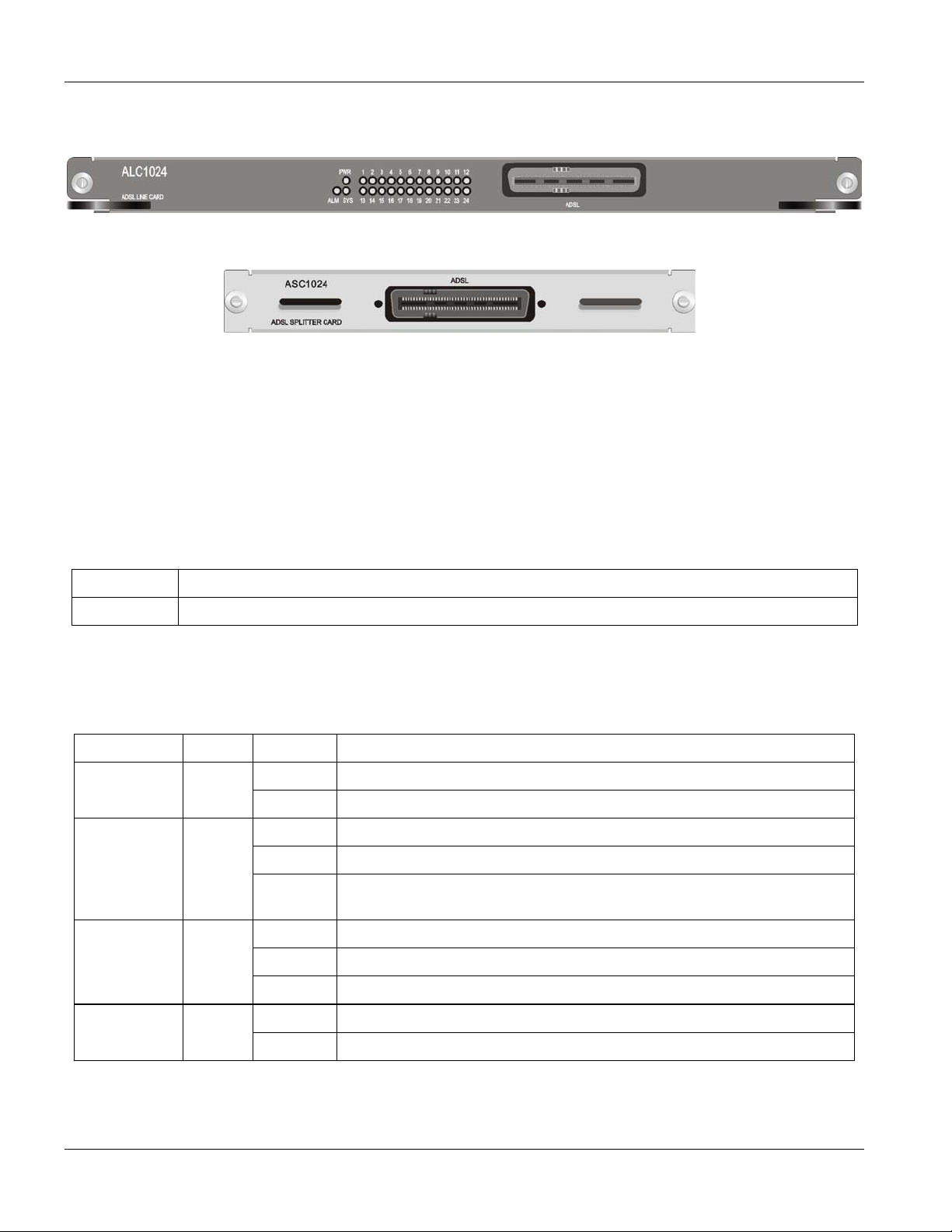
1.4 Front Panels
Figure 1-1 ALC1024 Front Panel
Figure 1-2 ASC1024 Front Panel
1.5 Hardware Specifications
These are the hardware details of the ALC1024 and ASC1024.
1.5.1 ALC1024 Ports
Table 1-1 ALC1024 Front Panel Ports
PORT DESCRIPTION
ADSL This Telco-50 connector is for connecting to the ASC1024 (ADSL Splitter Card).
1.5.2 ALC1024 LEDs
Table 1-2 LED Descriptions
LED COLOR STATUS DESCRIPTION
PWR Green On The system is up.
Off The system is off or not receiving power.
ALM Red Blinking The line card’s temperature and voltage monitoring hardware has failed.
On The line card has overheated or its voltage is out of the normal range.
Off The line card is functioning within its normal temperature and voltage
range.
SYS Green Blinking The line card is starting.
On The line card is on and functioning properly.
Off The line card is not receiving power, is not ready or has malfunctioned.
Green On The DSL link is up. ADSL (1-24)
Off The DSL link is down.
1-4 ALC1024 Overview
1.5.3 ASC1024 Ports
Table 1-3 ASC1024 Front Panel Ports
PORT DESCRIPTION
ADSL This Telco-50 connector is for connecting to the ALC1024 (ADSL Line Card).
1.5.4 Fuse Ratings
The ALC1024-61/63 uses one 5mm (D) x 20mm (L), T type, 4 amp, 250 Volt AC fuse.
The ALC1024-61L/63L uses one 5mm (D) x 20mm (L), T type, 5 amp, 250 Volt AC fuse.
1.5.5 Weight
ALC1024-61/63: 1.8 kg ALC1024-61L/63L: 2.2 kg
ASC1024: .8 kg
ALC1024 Overview
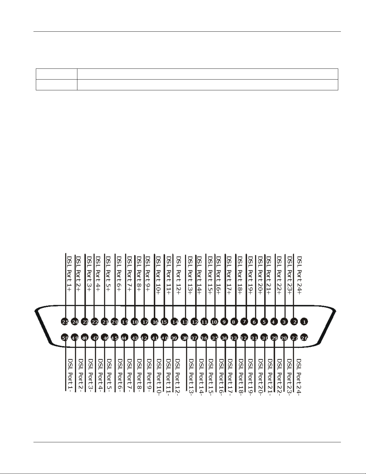
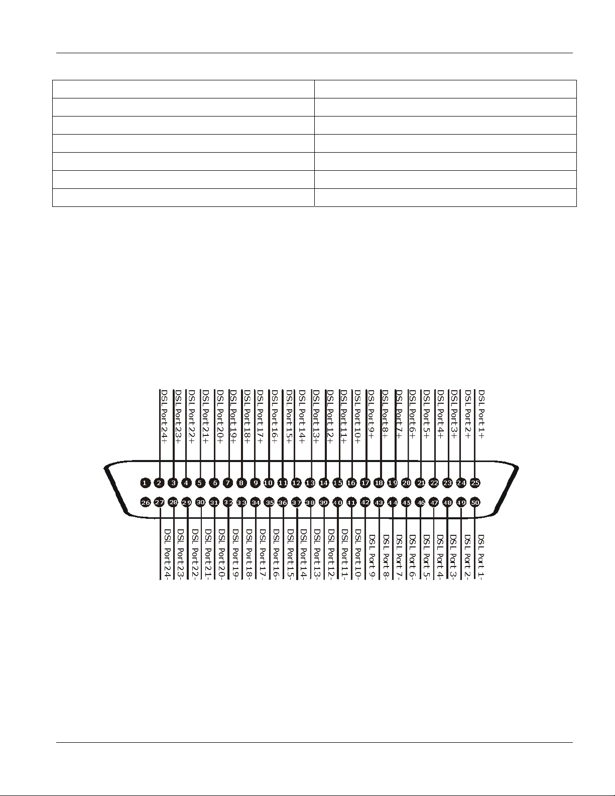
1.6 Hardware Telco-50 Connector Pin Assignments
The following diagram shows the pin assignments of the Telco-50 connectors on the ADSL line card, the ADSL
splitter card and the USER Telco-50 connectors on the IES splitter chassis’ rear panel. The pin assignments for
the IES splitter chassis with wire wrapping pins are the same as the ones shown for the Telco-50 connectors.
Figure 1-3 ALC1024, ASC1024, and USER Telco-50 Pin Assignments
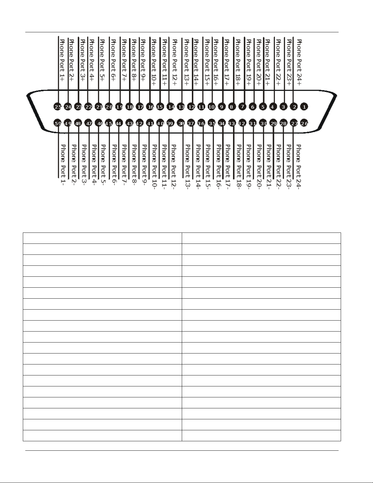
The following diagram shows the phone port pin assignments of the CO Telco-50 connectors on the splitter
chassis’ rear panel.
ALC1024 Overview 1-5
ALC1024 Overview
Figure 1-4 CO Telco-50 Pin Assignments
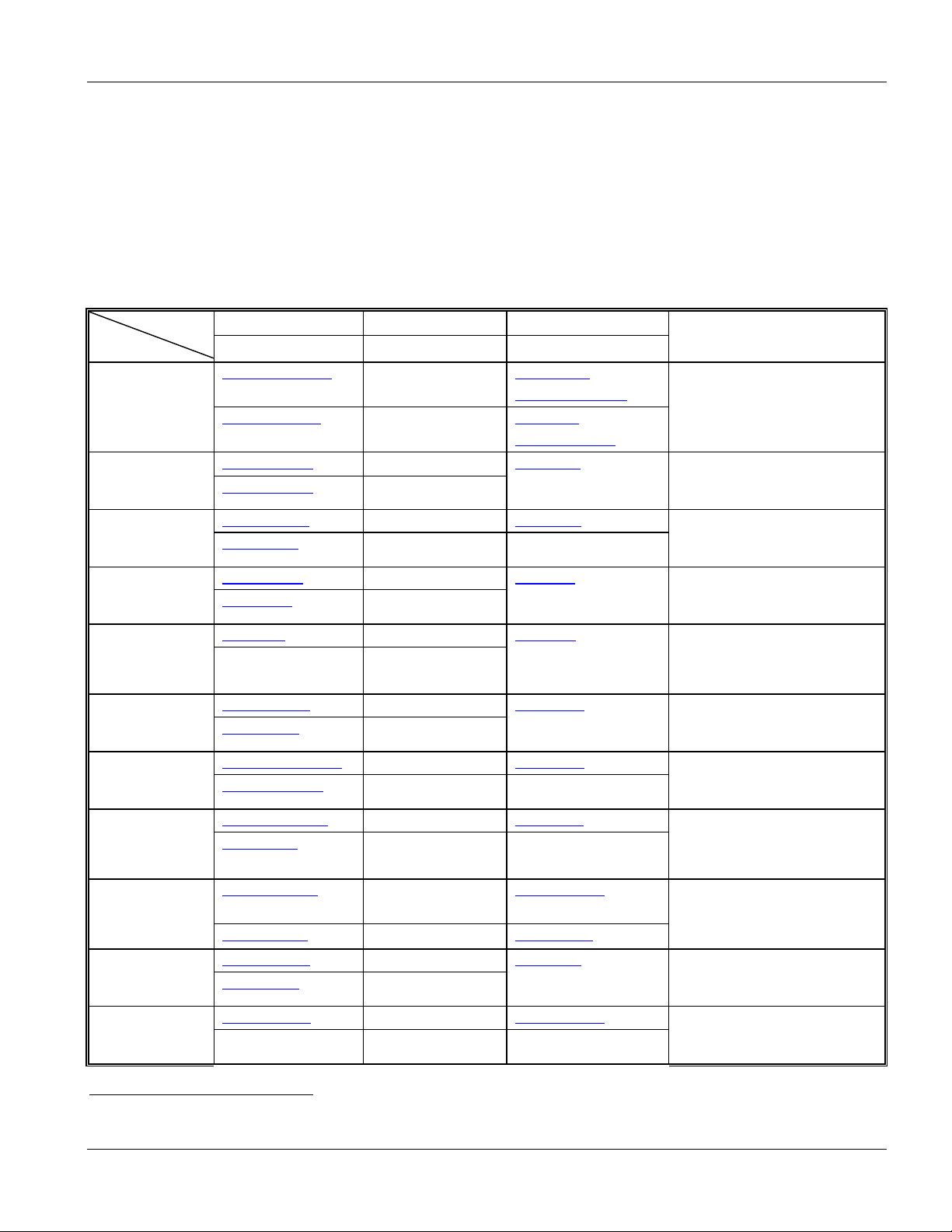
This table lists the ports and matching pin numbers for the hardware Telco-50 connectors.
Table 1-4 Hardware Telco-50 Connector Port and Pin Numbers
PORT NUMBER PIN NUMBER
1 25, 50
2 24, 49
3 23, 48
4 22, 47
5 21, 46
6 20, 45
7 19, 44
8 18, 43
9 17, 42
10 16, 41
11 15, 40
12 14, 39
13 13, 38
14 12, 37
15 11, 36
16 10, 35
17 9, 34
18 8, 33
1-6 ALC1024 Overview
ALC1024 Overview
Table 1-4 Hardware Telco-50 Connector Port and Pin Numbers
PORT NUMBER PIN NUMBER
19 7, 32
20 6, 31
21 5, 30
22 4, 29
23 3, 28
24 2, 27
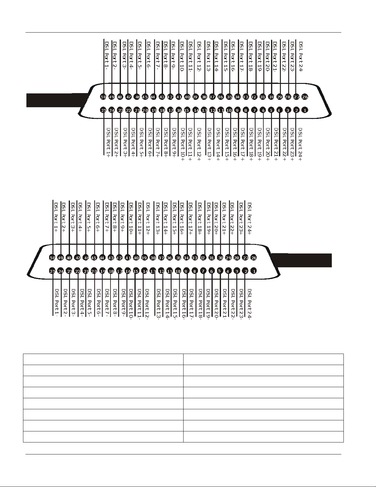
1.7 Telco-50 Cable Telco-50 Connector Pin Assignments
Use Telco-50 cables to connect the ADSL line card to the ADSL splitter card. The following diagrams show the
pin assignments that you need to have on the Telco-50 connectors on the Telco-50 cables.
See Table 1-5 for a list of the pin assignments.
1.7.1 Telco-50 Cable Telco-50 Connector Pin Assignments with the
IES-2000
Figure 1-5 IES-2000 Telco-50 Cable Telco-50 Connector Pin Assignments
1.7.2 Telco-50 Cable Telco-50 Connector Pin Assignments with the
IES-3000
The IES-3000 Telco-50 cable’s right Telco-50 connector connects to the splitter chassis card.
ALC1024 Overview 1-7
ALC1024 Overview
Figure 1-6 IES-3000 Telco-50 Cable Right Telco-50 Connector Pin Assignments
The IES-3000 Telco-50 cable’s left Telco-50 connector connects to the DSL line card.
Figure 1-7 IES-3000 Telco-50 Cable Left Telco-50 Connector Pin Assignments
Table 1-5 Telco-50 Cable Telco-50 Pin Assignments
PORT NUMBER PIN NUMBER
1 25, 50
2 24, 49
3 23, 48
4 22, 47
5 21, 46
6 20, 45
7 19, 44
1-8 ALC1024 Overview

Table 1-5 Telco-50 Cable Telco-50 Pin Assignments
PORT NUMBER PIN NUMBER
8 18, 43
9 17, 42
10 16, 41
11 15, 40
12 14, 39
13 13, 38
14 12, 37
15 11, 36
16 10, 35
17 9, 34
18 8, 33
19 7, 32
20 6, 31
ALC1024 Overview
21 5, 30
22 4, 29
23 3, 28
24 2, 27
ALC1024 Overview 1-9


Commands with MSC
Part II:
Commands with MSC
This part gives information on commands to use and how to use the web configurator to
configure and manage the ADSL line card with the Management Switch Card.
II

 Loading...