

Page 1

ZXMBWR9100
RemoteRadioUnit(2×4)
TechnicalManual
ZTECORPORATION
ZTEPlaza,KejiRoadSouth,
Hi-TechIndustrialPark,
NanshanDistrict,Shenzhen,
P .R.China
518057
Tel:(86)75526771900800-9830-9830
Fax:(86)75526772236
URL:http://support.zte.com.cn
E-mail:doc@zte.com.cn
Page 2

LEGALINFORMATION
Copyright©2006ZTECORPORATION.
Thecontentsofthisdocumentareprotectedbycopyrightlawsandinternationaltreaties.Anyreproductionordistributionof
thisdocumentoranyportionofthisdocument,inanyformbyanymeans,withoutthepriorwrittenconsentofZTECORPORATIONisprohibited.Additionally ,thecontentsofthisdocumentareprotectedbycontractualcondentialityobligations.
Allcompany ,brandandproductnamesaretradeorservicemarks,orregisteredtradeorservicemarks,ofZTECORPORA TION
oroftheirrespectiveowners.
Thisdocumentisprovided“asis”,andallexpress,implied,orstatutorywarranties,representationsorconditionsaredisclaimed,includingwithoutlimitationanyimpliedwarrantyofmerchantability ,tnessforaparticularpurpose,titleornon-infringement.ZTECORPORATIONanditslicensorsshallnotbeliablefordamagesresultingfromtheuseoforrelianceonthe
informationcontainedherein.
ZTECORPORATIONoritslicensorsmayhavecurrentorpendingintellectualpropertyrightsorapplicationscoveringthesubject
matterofthisdocument.ExceptasexpresslyprovidedinanywrittenlicensebetweenZTECORPORA TIONanditslicensee,
theuserofthisdocumentshallnotacquireanylicensetothesubjectmatterherein.
ZTECORPORATIONreservestherighttoupgradeormaketechnicalchangetothisproductwithoutfurthernotice.
UsersmayvisitZTEtechnicalsupportwebsitehttp://ensupport.zte.com.cntoinquirerelatedinformation.
TheultimaterighttointerpretthisproductresidesinZTECORPORATION.
RevisionHistory
RevisionNo.RevisionDateRevisionReason
R1.0
R1.1
02/04/2008FirstEdition
04/01/2008
Support3.5GHz
SerialNumber:sjzl20080369
Page 3

Content
Preface...............................................................i
ProductOverview..............................................1
R9100PositionintheNetwork..........................................1
R9100Appearance.........................................................2
R9100SystemStructure.................................................3
R9100Functions.............................................................3
R9100Features..............................................................4
TechnicalSpecications...................................................6
R9100EngineeringSpecications..................................6
R9100PowerSupplySpecications...............................7
R9100PowerConsumptionSpecications......................7
R9100RFPowerSpecications.....................................7
AppliedStandards..........................................................8
InternationalStandards...............................................8
LightningProofStandards............................................8
SafetyStandards........................................................9
EMCStandards...........................................................9
EnvironmentStandards..............................................10
HardwareDescription......................................13
Cabinet........................................................................13
R9100CabinetStructure............................................13
R9100InterfaceDescription........................................14
Modules.......................................................................15
ModulesConstituents.................................................15
WRFE.......................................................................15
WRFEFunctions................................................15
WRFEPerformanceSpecications........................16
WRPM......................................................................16
WRPMFunctions...............................................16
WRPMWorkPrinciple.........................................16
WDPA......................................................................17
Page 4

WDPAFunctions................................................17
WDPAWorkPrinciple.........................................17
WTRX......................................................................18
WTRXFunctions................................................18
WTRXWorkPrinciple.........................................19
Cables.........................................................................20
CablesList................................................................20
DCPowerCable.........................................................20
GroundingCable........................................................20
OpticalFiber.............................................................21
RFJumperCable.......................................................21
MainAntennaFeederSystem.........................................22
MainAntennaFeederSystemStructure........................22
AntennaStructure.....................................................24
Feeder.....................................................................24
ProtocolInterfaceDescription........................27
ASNNetworkReferenceModel.........................................27
R1Interface.................................................................29
R1InterfaceFunctions...............................................29
R1MessageFormat...................................................29
R1ProtocolStack......................................................29
MACLayerofR1ProtocolStack..........................30
PHYLayerofR1ProtocolStack...........................31
Baseband-RFInterface...................................................31
Baseband-RFInterfaceFunctions.................................31
OBSAIFrameStructure..............................................31
Baseband-RFInterfacePhysicalLayer..........................33
Figures............................................................35
Tables.............................................................37
Index..............................................................39
ListofGlossary................................................41
Page 5

PrerequisiteSkill
andKnowledge
WhatisinThis
Preface
PurposeThismanualprovidesZXMBWR9100RemoteRadioUnit(2x4)
productoverview,whichwillhelpthereadersknowtheproduct’s
function,principle,specication,features,cabinet,modules,
externalinterfacesandcables.
Intended
Audience
Manual
ThisdocumentisintendedforengineersandtechnicianswhoperformoperationactivitiesZXMBWR9100.
Tousethisdocumenteffectively ,usersshouldhaveageneralunderstandingofWiMAXsystem.Familiaritywiththefollowingis
helpful:
�WiMAXtechnology
�IEEE802.16e-Standard
�ZXMBWR9100anditsvariouscomponents
ThisManualcontainsthefollowingchapters:
Chapter
Chapter1ProductOverviewThischapterdescribesproduct’s
Chapter2Hardware
Description
Chapter3ProtocolInterface
Description
Summary
function,specication,featuresand
technicalspecications.
Thischapterdescribesproduct’smodule
functionandworkprinciple,cables’s
structureandmainantennasystem.
Thischapterdescribesproduct’sprotocol
interfaces.
ConfidentialandProprietaryInformationofZTECORPORATIONi
Page 6

ZXMBWR9100TechnicalManual
Thispageisintentionallyblank.
iiConfidentialandProprietaryInformationofZTECORPORATION
Page 7
Chapter1
ProductOverview
TableofContents:
R9100PositionintheNetwork..............................................1
R9100Appearance.............................................................2
R9100SystemStructure.....................................................3
R9100Functions................................................................3
R9100Features..................................................................4
TechnicalSpecications.......................................................6
AppliedStandards..............................................................8
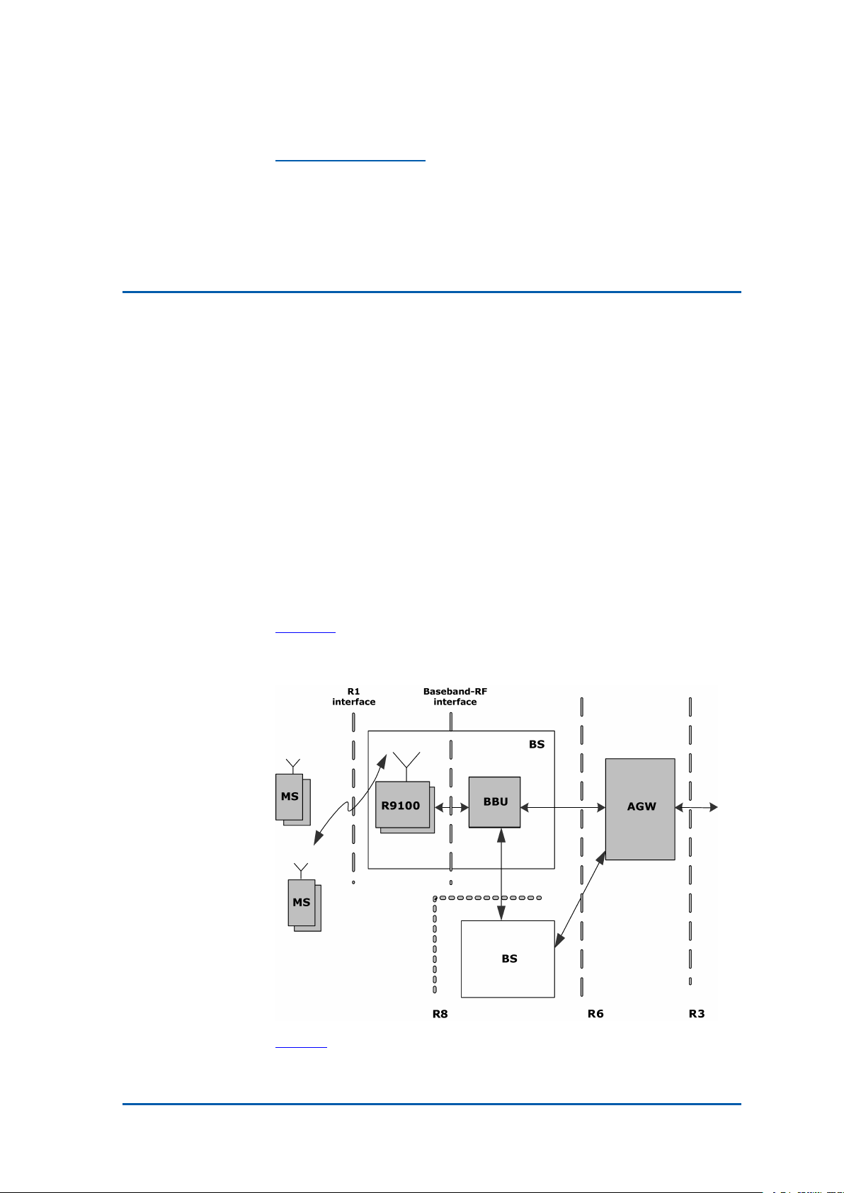
R9100Positioninthe Network
ThepositionZXMBWR9100inBaseStation(BS)isasshownin
Figure1.
FIGURE1ZXMBWR9100POSITIONINBS
Table1showsmeaningsofthenetworkelements.
ConfidentialandProprietaryInformationofZTECORPORATION1
Page 8
ZXMBWR9100TechnicalManual
TABLE1NETWORKELEMENTS
Name
AGW
BBU
BSBaseStation
MS
R9100
Meaning
AccessServiceNetworkGateWay
BasestationBasebandUnit
MobileStation
EnhancedRadioUnit(2carriers)
InterfacesofZXMBWR9100:
�Baseband-RFinterface:aninterfacebetweenR9100and
BBU,abidesbyOpenBaseStationArchitectureInitiative(OB-
SAI)RP3standard.
�R1interface:aninterfacebetweenBSandMS,abidesby
IEEE802.16e-2005protocol.
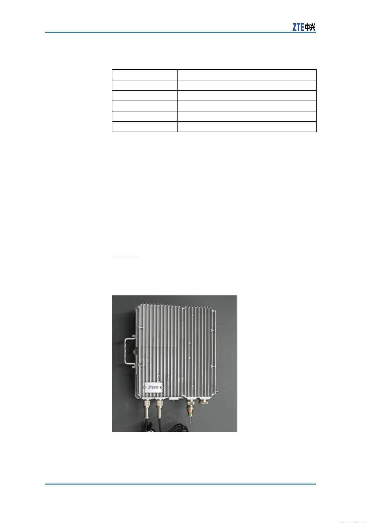
R9100Appearance
ZXMBWR9100radiounitismadeofcastaluminummetal.Itis
verysmallandexquisite.
Figure2showstheappearanceofZXMBWR9100.Thecabinet
surfaceiscoatedbysilvergraypaintthatissuitableforoutdoor
climate.
FIGURE2ZXMBWR9100APPEARANCE
2ConfidentialandProprietaryInformationofZTECORPORATION
Page 9
Chapter1ProductOverview
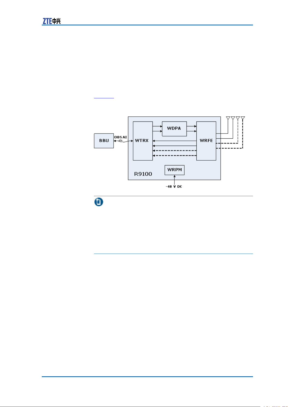
R9100SystemStructure
ZXMBWR9100isaremoteRadioFrequency(RF)unitthataccomplishestheconversionbetweentheRFsignalandbasebandsignal.
AnOpticalberisusedtoaccomplishthebasebanddatainterface
andbasebandI/Qinterface.RFcableisusedtoaccomplishthe
antennainterface.
Figure3showsZXMBWR9100systemstructure.
FIGURE3ZXMBWR9100SYSTEMSTRUCTURE
Note:
�Thereallineindicates2T×2RMultiple-InputMultipleOutput
(MIMO)andthedottedlineindicatesoptionalandsupports
2T×4RMIMO.
�FCCRFexposurestandardsrequirethatthisequipmentshould
beinstalledinsuchawayastomaintainaseparationdistance
of300cmbetweentheantennausedwiththisdeviceandall
thepersons.
�Forwardlink:WTRXreceivesforwardsignalsentbyBBUvia
anopticalinterface,performsdigitalintermediatefrequency
processingandup-conversion.WDPAperformssignalampli-
cation,thenWRFEperformsforwardltering,andnallysends
RFsignaltoairviaanantenna.
�Reverselink:WRFE
sendstoWTRXtoperformdown-conversionanddigitalintermediatefrequencyprocessingandnallysendstoBBUviaan
opticalinterface.
receivessignalfromanantenna,then
R9100Functions
AsaremoteRFunit,ZXMBWR9100performsthefollowingfunctions.
ConfidentialandProprietaryInformationofZTECORPORATION3
Page 10

ZXMBWR9100TechnicalManual
1.ForwardLinkFunctions
2.ReverseLinkFunctions
3.OtherFunctions
�ZXMBWR9100receivesIn-phaseandQuadraturephase
(I/Q)signalsfromBasestationBasebandUnit(BBU)viaopticalinterfaceforup-conversion.ZXMBWR9100Performs
RF
poweramplicationandtransmissionlteringonthere-
ceivedsignals,andthentransmitsthesignalsviaantenna.
�Providesstandingwavedetectionofantennafeederinter-
face.
�Providespowerdetectionofbasebandsignalsandantenna
feederinterface.
�Providesautomaticandmanualcalibration.
�ZXMBWR9100sendsthereceivedair-interfacesignalsto
BBUviaanopticalberafterbandpassltering.ZXMBW
R9100performslownoiseamplication,RFmixinganddigitaldown-conversiontobaseband.
�ProvidesReceivedSignalStrengthIndicator(RSSI)func-
tion.
�ProvidesAutomaticGainControl(AGC).
�Monitorsandmanagespowerampliersandpowersup-
plies.
�RegeneratesTimeDivisionDuplex(TDD)timesequence.
�Providesversionqueryandupdate.
�Supportsmeasurementsoftransmissiondelay .
�Restoresandregeneratesclocksattheberinterface.
�SupportsAISGelectricaltunableantennaandtrunknodes
monitoring.
R9100Features
ZXMBWR9100isdesignedforoutdooruse.Itisalsoapplicablein
basementsandcitysquares.
FollowingarethefeaturesofZXMBWR9100:
�ZXMBWR9100andBasebandunit(BBU)togetheraccomplish
BaseStation(BS)functions.
�Supportssinglecarriersuchas5MHz,7MHzor10MHz.
�Supports2Tx2Ror2Tx4RMultiple-InputMultiple-Output
(MIMO)technology(optional).
�SupportsWorldwideInteroperabilityforMicrowaveAccess
(WiMAX)bandclass2300MHz~2400MHzandbandclass
2490MHz2580MHzand2600MHz~2690MHzandbandclass
3400MHz~3500MHzandbandclass3500MHz~3600MHz.
4ConfidentialandProprietaryInformationofZTECORPORATION
Page 11

Chapter1ProductOverview
�Forbandclass2.3GHz,outputpowerisupto2x10W .For
bandclass2.5GHz,outputpowerisupto2x10W .Forband
class3.5GHz,outputpowerisupto2x4W.
�Workingtemperaturerangeisfrom-40°C~+55°Cand
supportsIP65shellprotectionlevel.
�Lightningprotectionlevelis15kA.
�Supportsremoteexternalmonitoringsuchasonehalf-duplex
RS232,onehalf-duplexRS485andseventrunknodesmonitoring(optional).
�TheBaseband-RFinterfacecomplieswithanOpenBaseSta-
tionArchitectureInitiative(OBSAI)standard.Supportsexible
networkingsuchasstarandchainnetworking.
�TheBaseband-RFinterfacesupportsopticalberbackup,thus
thereliabilityisincreased.
�Duetosmallsizeandlightweightprovideseasyinstallationand
maintenance.Itcanbeinstalledonpoles,wallsandracks.
�ManyZXMBWR9100scansharetheGlobalPositioningSystem
(GPS)ofbasebandpooltosavemoney.
�Externalantennaisused.Directionalantennaandomni-direc-
tionalantennaareavailable.
�Softwareremotedownloadisavailable.
�Remotecontrolboardresetisavailable.
�Supports-48VDCpowersupply.
�ComplieswiththeFCC
,CEandUnderwriterLaboratoriesInc.
(UL)certiedstandards.
�ComplieswithPart15oftheFCCRules.Operationissubject
totheconditionthatthisdevicedoesnotcauseharmfulinterference.
Caution:
Theuseriscautionedthatchangesormodicationsnotexpresslyapprovedbythepartyresponsibleforcompliancecould
voidtheuser’sauthoritytooperatetheequipment.
ConfidentialandProprietaryInformationofZTECORPORATION5
Page 12

ZXMBWR9100TechnicalManual
TechnicalSpecifications
R9100EngineeringSpecifications
Physical
Specications
PhysicalspecicationsofZXMBWR9100arelistedinTable2.
TABLE2PHYSICALSPECIFICATIONS
Name
Dimensions
Volume
Weight16.3kg(3515/16lb)
Shellprotectionlevel
ZXMBWR9100’sModules’Dimensions
WRFE(RFEfilter)
module
WRPM(Powersupply)
module
WDPA(Power
amplifier)module
WTRX(Transceiver)
module
Index
320mmx370mmx160mm(widthxheight
xdepth),i.e.,
1210/16inx149/16inx65/16in(width
xheightxdepth)
19L
IP65
200mmx230mmx25mm(widthxheight
xdepth),i.e.,
714/16inx91/16inx16/16in(widthx
heightxdepth)
80mmx250mmx40mm(widthxheightx
depth),i.e.,
32/16inx913/16inx19/16in(widthx
heightxdepth)
210mmx270mmx20mm(widthxheight
xdepth),i.e.,
84/16inx1010/16inx13/16in(widthx
heightxdepth)
210mmx330mmx25mm(widthxheight
xdepth),i.e.,
84/16inx1216/16inx16/16in(widthx
heightxdepth)
Temperature
andHumidity
Specications
6ConfidentialandProprietaryInformationofZTECORPORATION
TemperatureandhumidityspecicationsofZXMBWR9100are
listedinT able3.
TABLE3TEMPERATUREANDHUMIDITYSPECIFICATIONS
Name
Temperaturerequirement
HumidityrequirementWorkinghumidity:5%RH~95%RH
Index
Workingtemperature:-45°C~
+55°C
Storagetemperature:-45°C~
+85°C
Storagehumidity:5%RH~98%RH
Page 13

Chapter1ProductOverview
R9100PowerSupplySpecifications
Table4showsDCpowersupplyspecicationsforZXMBWR9100
torunnormally.
TABLE4POWERSUPPLYSPECIFICATIONS
Category
DC-48VDC-60VDC~-36VDC
NominalValuePowerSupplyRange
R9100PowerConsumption Specifications
Table5showsthepowerconsumptionspecicationsofZXMBW
R9100.
TABLE5POWERCONSUMPTIONSPECIFICATIONS
Name
Powerconsumption
Index
≤200W
R9100RFPowerSpecifications
Table6showsRadioFrequency(RF)powerspecicationsof
ZXMBWR9100.
TABLE6RFPOWERSPECIFICATIONS
Name
power
for2.3
GHz
power
for2.5
GHz
Output
power
for3.5
GHz
Carrier
Single
Double
Single
Double
Single
Double
ConfidentialandProprietaryInformationofZTECORPORATION7
Output
Power
10W Output
2x10W
10W Output
2x10W
4W
2x4W
PowerStep
0.5dB±15dB
Dynamic
Range
Page 14

ZXMBWR9100TechnicalManual
AppliedStandards
InternationalStandards
TheZXMBWR9100complieswiththefollowinginternationalstandards:
1.InstituteofElectricalandElectronicsEngineers(IEEE)Stan-
2.InstituteofElectricalandElectronicsEngineers(IEEE)Stan-
3.WorldwideInteroperabilityforMicrowaveAccess(WiMax)Fo-
4.WorldwideInteroperabilityforMicrowaveAccess(WiMAX)
5.WorldwideInteroperabilityforMicrowaveAccess(WiMAX)Fo-
6.OpenBaseStationArchitectureInitiative(OBSAI)Reference
dard802.16-2004,IEEEStandardforLocalandMetropolitan
AreaNetworks-Part16:AirInterfaceforFixedWirelessAccessSystems.
dard802.16-2005,Part16:AirInterfaceforFixedandMobile
BroadbandWirelessAccessSystems.
TM
rum
Forum
ment(PICS)Proforma.
rum
Point3SpecicationVersion3.0.
MobileRadioConformanceTests(MRCT).
TM
MobileProtocolImplementationConformanceState-
TM
MobileSystemProle.
LightningProofStandards
TheZXMBWR9100complieswiththefollowinglightningproof
standards:
1.InternationalElectrotechnicalCommission(IEC
(1995)ProtectionagainstLightningElectromagneticImpulse
PartI:GeneralPrinciples.
2.InternationalElectrotechnicalCommission(IEC)61643-1
(1998)SurgeProtectivedevicesconnectedtolow-voltage
powerdistributionsystems.
3.InternationalTelecommunicationsUnion(ITU
PrinciplesofProtectionagainstOvervoltageandOvercurrent.
4.InternationalTelecommunicationsUnion(ITU)-TK.27(1996)
BondingCongurationsandEarthingInsideaT elecommunicationBuilding.
5.EuropeanTelecommunicationStandard(ETS
EquipmentEngineering;Earthingandbondingoftelecommunicationequipmentintelecommunicationcentres.
)300253(2004)
)61312-1
)-TK.11(1993)
8ConfidentialandProprietaryInformationofZTECORPORATION
Page 15

Chapter1ProductOverview
SafetyStandards
TheZXMBWR9100complieswiththefollowingsafetystandards:
1.InternationalElectrotechnicalCommission(IEC)60950Safety
ofinformationtechnologyequipmentincludingElectricalBusinessEquipment.
2.InternationalElectrotechnicalCommission(IEC)60215Safety
requirementforradiotransmittingequipment.
3.CanadianStandardsAssociation(CAN/CSA)-C22.2No1-M94
Audio,VideoandsimilarElectronicEquipment.
4.CanadianStandardsAssociation(CAN/CSA)-C22.2No950-95
SafetyofInformationT echnologyEquipmentincludingElectricalBusinessEquipment.
5.UniversityofLimerick(UL)1419StandardforProfessional
VideoandAudioEquipment.
6.73/23/ElectricalandEletronicsCommission(EEC)LowVoltage
Directive.
7.UniversityofLimerick(UL)1950SafetyofinformationtechnologyequipmentincludingElectricalBusinessEquipment.
8.InternationalElectrotechnicalCommission(IEC)60529Classicationofdegreesofprotectionprovidedbyenclosure(IP
Code).
9.GOST30631-99.GeneralRequirementstomachines,instrumentsandotherindustrialarticlesonstabilitytoexternalmechanicalimpactswhileoperating.
10.GOST12.2.007.0-75.Electro-technicaldevices.Thegeneral
safetyrequirements.
EMCStandards
TheZXMBWR9100complieswiththefollowingEMCstandards:
1.IECSpecialInternationalCommitteeonRadioInterference
(CISPR)22(1997):Limitsandmethodsofmeasurementof
radiodisturbancecharacteristicsofinformationtechnology
equipment.
2.EN301489-1Part1:Commontechnicalrequirements.
3.InternationalElectrotechnicalCommission(IEC)61000-6-1:
1997:ElectromagneticCompatibility(EMC)-Part6:Generic
standards-Section1:Immunityforresidential,commercial
andlight-industrialenvironments.
4.InternationalElectrotechnicalCommission(IEC)61000-6-3:
1996:ElectromagneticCompatibility(EMC)-Part6:Generic
standards-Section3:missionstandardforresidential,commercialandlightindustrialenvironments.
5.InternationalElectrotechnicalCommission(IEC)61000-4-2
(1995):ElectromagneticCompatibility(EMC)-Part4:T est-
ConfidentialandProprietaryInformationofZTECORPORATION9
Page 16

ZXMBWR9100TechnicalManual
6.InternationalElectrotechnicalCommission(IEC)61000-4-3
7.InternationalElectrotechnicalCommission(IEC)61000-4-4
8.InternationalElectrotechnicalCommission(IEC)61000-4-5
9.InternationalElectrotechnicalCommission(IEC)61000-4-6
10.InternationalT elecommunicationsUnion(ITU)-TRecommen-
11.GOSTR51318.22-99:Electromagneticcompatibilityoftech-
12.GOST30429-96:Electromagneticcompatibilityoftechnical
ingandmeasurementtechniques-Section2:Electrostatic
dischargeimmunitytest.
(1995):ElectromagneticCompatibility(EMC)-Part4:T esting
andmeasurementtechniques-Section3:Radiated,radio-frequencyelectromagneticeldimmunitytest.
(1995):ElectromagneticCompatibility(EMC)-Part4:T esting
andmeasurementtechniques-Section4:Electricalfast
transient/burstimmunitytest.
(1995):Electro-MagneticCompatibility(EMC
ingandmeasurementtechniques-Section5:Surgeimmunity
test.
(1996):Electro-MagneticCompatibility(EMC)-Part4:
Testingandmeasurementtechniques-Section6:Immunity
tocontacteddisturbances,inducedbyradiofrequencyelds.
dationK.20:ResistibilityofT elecommunicationSwitching
EquipmenttoOvervoltagesandOvercurrents.
nicalequipment.Man-madenoisefrominformationalequipment.Limitsandtestmethods.
equipment.Man-madenoisefromequipmentandapparatus
usedtogetherwithservicereceiversystemsofcivilapplication.Limitsandtestmethods.
)-Part4:T est-
EnvironmentStandards
TheZXMBWR9100complieswiththefollowingenvironmentstandards:
1.InternationalElectrotechnicalCommission(IEC
greesofprotectionprovidedbyenclosure(IPcode)".
2.InternationalElectrotechnicalCommission(IEC)60721-3-1:
Classicationofenvironmentalconditions-Part3:Classicationofgroupsofenvironmentalparametersandtheirseverities-Section1:Storage
3.InternationalElectrotechnicalCommission(IEC)60721-3-2:
Classicationofenvironmentalconditions-Part3:Classicationofgroupsofenvironmentalparametersandtheirseverities-Section2:T ransportation.
4.InternationalElectrotechnicalCommission(IEC)60721-3-3
(1994):Classicationofenvironmentalconditions-Part3:
Classicationofgroupsofenvironmentalparametersandtheir
severities-Section3:Stationaryuseatweatherprotected
locations.
5.EuropeanTelecommunicationStandard(ETS
EquipmentEngineering(EE);Environmentalconditionsand
)60529"De-
)300019-2-1:
10ConfidentialandProprietaryInformationofZTECORPORATION
Page 17

Chapter1ProductOverview
environmentaltestsfortelecommunicationsequipment;Part
2-1,SpecicationofenvironmentaltestsStorage.
6.EuropeanTelecommunicationStandard(ETS)300019-2-2:
EquipmentEngineering(EE
);Environmentalconditionsand
environmentaltestsfortelecommunicationsequipment;Part
2-2,SpecicationofenvironmentaltestsT ransportation.
7.EuropeanTelecommunicationStandard(ETS)300019-2-3:
EquipmentEngineering(EE);Environmentalconditionsand
environmentaltestsfortelecommunicationsequipment;Part
2-3,SpecicationofenvironmentaltestsT ransportationStationaryuseatweather-protectedlocations.
8.InternationalElectrotechnicalCommission(IEC)60068-2-1
(1990):Environmentaltesting-Part2:Tests.T estsA:Cold.
9.InternationalElectrotechnicalCommission(IEC)60068-2-2
(1974):Environmentaltesting-Part2:T ests.T estsB:Dry
heat.
10.InternationalElectrotechnicalCommission(IEC)60068-2-6
(1995):Environmentaltesting-Part2:Tests-TestFc:
Vibration(sinusoidal).
11.GOST15150-69:Machines,instrumentsandotherindustrial
articles.Applicationsfordifferentclimaticregions.Categories,
operating,storageandtransportationconditionsincompliance
withtheenvironmentalfactors.
12.GOST23088-80:Electronicequipment.Requirementsto
packingandtransportationandtestmethods.
ConfidentialandProprietaryInformationofZTECORPORATION11
Page 18

ZXMBWR9100TechnicalManual
Thispageisintentionallyblank.
12ConfidentialandProprietaryInformationofZTECORPORATION
Page 19

Chapter2
HardwareDescription
TableofContents:
Cabinet............................................................................13
Modules...........................................................................15
Cables.............................................................................20
MainAntennaFeederSystem.............................................22
Cabinet
R9100CabinetStructure
Figure4showsthecabinetstructureofZXMBWR9100.
FIGURE4ZXMBWR9100CABINETSTRUCTURE
1.Cabinet
2.BottomPanel
3.Handle
ConfidentialandProprietaryInformationofZTECORPORATION13
Page 20

ZXMBWR9100TechnicalManual
R9100InterfaceDescription
ShortDescriptionTheZXMBWR9100ishighlyintegrated.Onlyfourmodulesare
usedandmanyexternalinterfacesareavailableonthepanel.The
powerinterfaceconnectswiththeWRPMmodule,RFantennainterfaceconnectswiththeWRFEmoduleandBDS-RFSOpticalFiber
interfacesconnectwiththeWTRXmodule.
ZXMBWR9100
External
Interfaces
ExternalinterfacesarelocatedontheZXMBWR9100bottomplate.
Figure5showsthepositionoftheinterfacesontheZXMBWR9100
panel.
FIGURE5ZXMBWR9100EXTERNALINTERFACES
1.BDS-RFSOpticalFiber(LC1/2)
2.AntennaInterfaceStandardGroup
(AISG)
3.MonitoringInterface(MON)
Interface
Description
able7ListsthedescriptionoftheexternalinterfacesofZXMBW
T
R9100cabinet.
TABLE7ZXMBWR9100EXTERNALINTERFACEDESCRIPTION
Interface
BDS-RFSFiberOptical
(LC1/2)
AntennaInterface
StandardGroup(AISG)
MonitoringInterface
(MON)
PowerInterface(DCIN)
Description
ThisinterfaceconnectstheODF.
Thisisthetestinterface.TheIndoorAISG
controlcableconnectstheWTRXboard.
TheoutdoorAISGcontrolcableconnects
theantennaforadjustingtheazimuthof
theantenna.
Themonitoringcableconnectsbetween
theMONinterfaceonthecabinetwiththe
variousmonitoringdevices.
-48VDCpowercableconnectsbetweenDC
INandthepowersource.
4.PowerInterface(DCIN)
5.RFAntennaInterface(Port2/3)
6.RFAntennaInterface(Port0/1)
14ConfidentialandProprietaryInformationofZTECORPORATION
Page 21

Chapter2HardwareDescription
Interface
RFAntennaInterface
(Port2/3)
RFAntennaInterface
(Port0/1)
Description
TheRFcableconnectstheAntennawith
theport2/3ofthecabinet.
TheRFcableconnectstheAntennawith
theport0/1ofthecabinet.
Modules
ModulesConstituents
TheZXMBWR9100iscomposedofWRFE,WRPM,WDPA,and
WTRXmodules.Thephysicaldescriptionofthesemodulesare
givenbelow.
�WiMAXRFFrontEndFilter(WRFE)
ThedimensionofWRFEmoduleis200mmX230mmX25mm
(widthXheightXdepth),excludingconnector .
�WiMAXRRUPowerModule(WRPM)
ThedimensionofWRPMmoduleis80mmX250mmX40mm
(widthXheightXdepth),excludingconnector .
�WiMAXDigitalPowerAmplier(WDPA)
ThedimensionofWDPAmoduleis210mmX270mmX20mm
(widthXheightXdepth),excludingconnector .
�WiMAXT ransmitter&Receiver(WTRX)
ThedimensionofWTRXmoduleis210mmX330mmX25mm
(widthXheightXdepth),excludingconnector .
WRFE
WRFEFunctions
ShortDescriptionTheWRFEmoduleistheWiMAXRFFrontEndFiltermoduleof
ZXMBWR9100.
TheWRFE
�TransfersRF
�FiltersRFsignals.
�ProvideslightningproofforRF
�Isolatesuplinkanddownlinkasthereceivingandtransmitting
powerisdifferent.
moduleperformsthefollowingfunctions.
signaltoantenna.
unit.
ConfidentialandProprietaryInformationofZTECORPORATION15
Page 22

ZXMBWR9100TechnicalManual
WRFEPerformanceSpecifications
ShortDescriptionThefollowingdescribestheperformancespecicationsofthe
WRFEmodule.
WRFEPerfor-
manceSpeci-
cations
Table8liststheperformancespecicationsofWRFEmodule.
TABLE8WRFEPERFORMANCESPECIFICATIONS
Index
Frequencyrange
2300MHz~2400MHz
2490MHz~2580MHz
2600MHz~2690MHz
3400MHz~3500MHz
3500MHz~3600MHz
Range
WRPM
WRPMFunctions
ShortDescriptionInZXMBWR9100,theWiMAXRRUPowerModule(WRPM)isre-
sponsibleforpowersupplyconversion.TheWRPMmoduleisoptionalinsystemconguration.
TheWRPMmoduleperformsthefollowingfunctions.
�Powersupplyconversion
�Lightningproof
�EMIltering
�Powersupplymanagementandalarm.
WRPMWorkPrinciple
ShortDescriptionThefollowingdescribestheworkprincipleofWRPMmodule.
16ConfidentialandProprietaryInformationofZTECORPORATION
Page 23

Chapter2HardwareDescription
WRPMWork
Principle
DescriptionTheWRPMmoduleconsistsofanEMIlteringunit,protectionunit,
Figure6showstheworkprincipleblockdiagramofWRPMmodule.
FIGURE6WRPMWORKPRINCIPLE
DC-DCconversionunitandalarmmonitoringunit.Thefunctionof
eachcomponentisintroducedbelow.
�EMIlteringunitprovideslteringfunction.
�Protectionunitprovidesover-voltageorunder-voltagepro-
tection.
�DC-DCconversionunitprovidespowersupplyconversion.
�Alarmmonitoringunitreportstheunder-voltage,over-volt-
ageandover-currentalarms.
WDPA
WDPAFunctions
ShortDescriptionInZXMBWR9100,theWiMAXDigitalPowerAmplier(WDPA)
moduleampliestheRFpower .
TheWDPA
�RFamplication
�VSWRmeasurement
�Alarmreporting
WDPAWorkPrinciple
ShortDescriptionThefollowingdescribestheworkingprincipleofWiMAXDigital
PowerAmplier(WDPA)module.
moduleperformsthefollowingfunctions:
ConfidentialandProprietaryInformationofZTECORPORATION17
Page 24

ZXMBWR9100TechnicalManual
WDPAWork
Principle
DescriptionTheWDPAmoduleconsistsofanampliercircuit,circulator ,cou-
Figure7showstheworkprincipleblockdiagramofWDPAmodule.
FIGURE7WDPAWORKPRINCIPLE
pler ,powersupply ,alarmreportingunitandLNA
eachunitisdescribedbelow.
�AmpliercircuitprovidesthemainRFamplicationchannel.
�Circulatorseparatesthereceivingandsendingsignals.
�CouplerextractstheRFsignaltransmittedbybasestation.It
isresponsibleformonitoringandmeasuringRFsignal.
�Powersupplyunitprovidespowersupplyforeachunit.
�Alarmreportingunitreportsthetemperature,high/low
powerandstandingwavealarms.
�LowNoiseAmplier(LNA)ampliesthereceivedsignals.
.Thefunctionof
WTRX
WTRXFunctions
ShortDescriptionInZXMBWR9100,theWiMAXTransmitter&Receiver(WTRX)
moduleisusedforRFup/down-conversion.
TheWTRXmoduleperformsthefollowingfunctions:
�BasebandRFclockextracting,restoringanddistributing
�RRUcentralizedmonitoring
�Digitalintermediatefrequencyprocessing
�RFsmallsignalup/down-conversion
�Powersupplygeneration
�SupportsOBSAI-RP3interface.
18ConfidentialandProprietaryInformationofZTECORPORATION
Page 25

WTRXWorkPrinciple
Chapter2HardwareDescription
WTRXWork
Principle
DescriptionTheWTRXmoduleconsistsofanOpticalberinterfacecircuit,In-
Figure8showstheworkprincipleblockdiagramofWTRXmodule.
FIGURE8WTRXWORKPRINCIPLE
termediatefrequencyprocessingcircuit,Clockprocessingcircuit,
processingcircuit,Centralizedmonitoringcircuit,andPower
RF
supplyprocessingcircuit.Thefunctionofeachunitisdescribed
below.
�OpticalberinterfacecircuitinterfaceswithBBU
supportsopticalberloopbacknetworkingandopticalber
concatenatingnetworking.Theframepackingandunpacking
inopticalberarealsosupported.
�IntermediatefrequencyprocessingcircuitandRFpro-
cessingcircuitaccomplishestheforwardtransmission
process;receivesbasebandsignal,performsup-conversion
andsendstopoweramplierafteramplication.Italso
performsstandingwavecheckingatantennafeederinterface,
forwardautomaticcalibrationandmanualcalibration.
Thecircuitalsoaccomplishesthereversereceivingprocess;
receivesRFWiMAXsignalinreversedirection;performspass
bandltering,lownoiseamplication,RFfrequencymixingand
digitaldown-conversiontobasebandrate.Afteropticalinterfaceprocessing,thesignalistransmittedtoBasestationBasebandUnit(BBU)viaanOpenBaseStationArchitectureInitiative(OBSAI)protocol.ItalsoperformsthereverseReceived
SignalStrengthIndicator(RSSI)measurementandAutomatic
GainControl(AGC).
�Clockprocessingcircuitrestores,converts,anddistributes
theclocks.Italsoreportsthetemperature,low/highpower ,
andstandingwavealarms.
�Centralizedmonitoringcircuitmonitorsandmanagesthe
powersupply,versionandelectronicadjustingantenna.It
monitorstheexteriordevicesviatrunkingnodeandRS232
RS485.ItalsoregeneratestheTDDtimesequences.
,andit
or
ConfidentialandProprietaryInformationofZTECORPORATION19
Page 26

ZXMBWR9100TechnicalManual
�Powersupplyprocessingcircuitprovidespowersupplyfor
Cables
CablesList
TheZXMBWR9100usesthefollowingcablesaccordingtotheapplications:
�PowerSupplycable
�Groundingcable
�Opticalber
�RFJumper
eachunit.
DCPowerCable
CurrentlyZXMBWR9100supports-48VDCpowersupplyonly.
ThepowercabledirectlyconnectsDCinputpowersourcewithDC
INinterfaceatZXMBWR9100cabinetbottom.
Figure9showsthestructureof-48VDCpowercable.
FIGURE9ZXMBWR9100DCPOWERCABLESTRUCTURE
GroundingCable
Thegroundingcableismadeof10mm
preventioncable.Circularunsheathedcrimpingconnectors(lug)
areusedatbothends(AandB).
Figure10showsthestructureofgroundingcable.
2
yellow/greenburning-
20ConfidentialandProprietaryInformationofZTECORPORATION
Page 27

FIGURE10GROUNDINGCABLESTRUCTURE
OpticalFiber
Chapter2HardwareDescription
OpticalFiber
Structure
DescriptionThefollowingdescribessomeofthekeypointsrelatedtothephys-
Figure11showstheopticalberstructureusedinZXMBWR9100.
FIGURE11ZXMBWR9100OPTICALFIBERSTRUCTURE
icalstructureofthebercable.
�ThecableisasinglemodeberwithLC/PC-DLC/PCconnector .
�Thesheathusuallyisblack.Thetwocorewiresareyellowand
blue.
�Thesheathdiameteris7mm.
RFJumperCable
RFjumpercableisusedtotransfersignalsbetweenZXMBW
R9100cabinetandantenna,betweenZXMBWR9100cabinetand
mainfeedercable,andbetweenmainfeedercableandantenna.
ThelengthoftheRFjumpercableisdeterminedaccordingtothe
actualsituation.
WhenthedistancebetweenantennaandZXMBWR9100cabinetis
lessandtheadoptedfeedercableisof1/2in.then,thejumpercableisnotused,ratherZXMBWR9100cabinetisdirectlyconnected
withthefeedercableandfeedercableisconnectedtotheantenna.
Iftheadoptedfeedercableisof7/8in.or5/4in.thenjumperis
used.Figure12showstheRFjumpercable.
ConfidentialandProprietaryInformationofZTECORPORATION21
Page 28

ZXMBWR9100TechnicalManual
FIGURE12RFJUMPERCABLE
MainAntennaFeeder System
MainAntennaFeederSystem Structure
Themainantennafeedersystemconsistsoftheequipmentsrelatedtoantennaandfeeder .
Figure13illustratesatypicalstructureofthemainantennafeeder
system.
22ConfidentialandProprietaryInformationofZTECORPORATION
Page 29

FIGURE13MAINANTENNAFEEDERSYSTEMSTRUCTURE
Chapter2HardwareDescription
1.LightningRod
2.Antenna
3.Antennajumpers
4.Lightningproofgroundingclip
5.Mainfeedercable
6.Irontower
7.Cablingrack
8.Cabinetjumper
9.Cabinet
Note:
�SinceRFtransmissionpowerofZXMBWR9100isrelatively
weak,theantennaisinstallednearertothecabinet.Itusually
adoptsself-carriedfeedercable.1/2″or7/8"feedercables
areadoptedonlywhentheantennaisfarfromthecabinet.
�Usually,thenumberofantennasrangebetweentwotofour .
ConfidentialandProprietaryInformationofZTECORPORATION23
Page 30

ZXMBWR9100TechnicalManual
AntennaStructure
Antennaisanimportantradioequipmentadoptedtotransmitand
receiveelectromagneticwave.Antennaisdividedintoomniantennaanddirectionalantennabyradiationdirection;accordingto
polarizationmode,antennacanbedividedintosingle-polarized
antennaandbi-polarizationantenna.Figure14illustratestheap-
pearanceofomniantennaanddirectionalantenna.
FIGURE14THEAPPEARANCEOFOMNIANTENNAANDDIRECTIONALANTENNA
Feeder
ThefeederisusedtoreceiveandtransmitradioRFsignalsbetween
theantennaandtheZXMBWR9100.Therearemanytypesof
feedercablessuchas1/2inchand7/8inchfeedercable.
WhenthedistancebetweentheZXMBWR9100cabinetandantennaisless,then1/2inchfeedercableisused.Inthiscase,
ZXMBWR9100cabinetisdirectlyconnectedtothe1/2inchfeeder
and1/2inchfeedercableisconnectedtoantenna.
WhenthedistancebetweentheZXMBWR9100cabinetandantennaismore,then7/8inchfeedercableisused.Inthiscase,
ZXMBWR9100cabinetisrstconnectedtothejumper ,then
jumperisconnectedto7/8inchfeedercable,and7/8inchfeeder
24ConfidentialandProprietaryInformationofZTECORPORATION
Page 31

Chapter2HardwareDescription
cableisagainconnectedtojumperandlastlyjumperisconnected
toantenna.
TheantennamayhaveNtypeorDINtypeinterface.Thefeeder
isadaptedtofemaleandmaleNconnectors.Usuallybothends
ofthedeliveredfeederaremaleNconnectortofacilitateon-site
installation.
ConfidentialandProprietaryInformationofZTECORPORATION25
Page 32

ZXMBWR9100TechnicalManual
Thispageisintentionallyblank.
26ConfidentialandProprietaryInformationofZTECORPORATION
Page 33

Chapter3
ProtocolInterface Description
TableofContents:
ASNNetworkReferenceModel.............................................27
R1Interface.....................................................................29
Baseband-RFInterface.......................................................31
ASNNetworkReference Model
ThefollowingdescribestheAccessServiceNetwork(ASN)network
referencemodel.TheASNnetworkreferencemodeldeveloped
bytheWiMAX(WorldwideInter-operabilityforMicrowaveAccess)
NWG(NetWorkGroup)isshowninFigure15.
ConfidentialandProprietaryInformationofZTECORPORATION27
Page 34

ZXMBWR9100TechnicalManual
FIGURE15ASNNETWORKREFERENCEMODEL
TheinterfaceofFigure15aredescribedinT able9.
TABLE9INTERFACESDESCRIPTION
Interface
Name
R1
R3
R4
R6
R7
R8
Description
AirinterfacebetweentheterminalandtheRRU.
TheinterfacebetweentheAGW(ASN-GW,Access
ServiceNetworkGateWay)andtheCN.
InterfacebetweenASNs,i.e.theinterfacebetween
AGWs.Itimplementssomeswitching-related
signalingandestablisheddatachanneltomaintain
dataintegrityduringswitching.
TheinterfacebetweentheAGWandtheBS.
InternalinterfaceoftheAGW.Itisselective.It
dividestheAGWintostrategyjudgmentfunction
andimplementingfunction.
InterfacebetweenBSs.
28ConfidentialandProprietaryInformationofZTECORPORATION
Page 35

Chapter3ProtocolInterfaceDescription
R1Interface
R1InterfaceFunctions
TheR1interfaceperformsthefollowingfunctions:
�Co-operateswiththeBasestationBasebandUnit(BBU)to
performmeasurement,management,andcontrolofradio
resources.
�ReceivesandtransmitsRFsignals.
R1MessageFormat
DescriptionFigure16illustratesmanagementmessageformatoftheR1inter-
faceofMediaAccessControl(MAC)Layer .
FIGURE16R1MESSAGEFORMAT
ThemanagementmessagesofMACLayerarepresentedinMAC
ProtocolDataUnit(PDU)payload.Allmanagementmessagesof
MACLayerarecomposedofaninitialeld"ManagementMessage
Type"and"ManagementMessagePayload".Thelengthofthe
"ManagementMessageType"is8bit;thetypeofthemanagementmessagedependsontherequirementsofanairinterface
protocolinIEEE802.16.
TheMACmanagementmessagesinbasicconnection,broadcast
connection,andinitialdistance-testingconnectionarenotdivided
intochipsorboundintopackets.ButtheMACmanagementmessagesintheprimarymanagementconnectioncanbedividedinto
chipsorboundintopackets.
R1ProtocolStack
OverviewFigure17illustratesaschematicdiagramofR1InterfaceProtocol
Stack.
ConfidentialandProprietaryInformationofZTECORPORATION29
Page 36

ZXMBWR9100TechnicalManual
FIGURE17R1INTERFACEPROTOCOLSTACK
TheR1interfaceprotocolstackincludesMACLayerandPHYLayer .
MACLayerofR1ProtocolStack
DescriptionMAClayerofR1protocolstackcontainsthreesub-layers(fromtop
tobottom);Service-SpecicConvergenceSub-layer(CS),MAC
CommonPartSub-layer(MACCPS
1.Service-SpecicConvergenceSub-layer(CS)
DifferentprotocolinterfacesprovidedifferentCSspecications.
ThefunctionofService-SpecicConvergenceSub-layer(CS)
istoconvert/maptheexternaldatareceivedbytheConvergenceSub-layerServiceAccessPoint(CSSAP)intoMACServiceDataUnit(MACSDU)andsendittotheMACCPSthrough
theMACServiceAccessPoint(MACSAP).Theotherfunction
ofthislayeristosortexternalSDUsassociatedwithsuitable
ServiceFlowIdentier(SFID),ConnectionIdentier(CID)and
PayloadHeaderSuppression(PHS).
2.MACCommonPartSub-layer(MACCPS)
MACCPSdoesnotneedtoanalyzetheloadinformationofthe
CS.
MACCPSrealizesthecorefunctionoftheMAClayerincludingbandwidthdistribution,connectionestablishmentandconnectionmaintenance.ItreceivesdataofdifferentCSlayers
throughMACSAPandsortthembasedondifferentMACconnection.QualityofService(QoS)isappliedindatatransmissionandschedulingofphysicallayer .
Data,PHYcontrolinformationandstatisticalinformationbetweentheMACCPSandPHYistransmittedthroughPHYSAP .
3.SecuritySub-layer
MACcontainsanindependentsecuritysub-layertoprovideauthentication,securitykeyexchangeandrealizeencryption.
)andSecuritySub-layer .
30ConfidentialandProprietaryInformationofZTECORPORATION
Page 37

Chapter3ProtocolInterfaceDescription
PHYLayerofR1ProtocolStack
DescriptionThePHYlayerofR1protocolstackcontainsmultipleregulations.
Eachregulationcorrespondstoaspecicfrequencyrangeandapplication.
ThePHYlayerofR1protocolstackisbasedonthemodulating
modeofOrthogonalFrequencyDivisionMultiplexing(OFDM).
Baseband-RFInterface
Baseband-RFInterfaceFunctions
TheZXMBWR9100baseband-RFinterfaceperformsthefollowing
functions:
�Datatransmissionfromber-opticalinterfaces
�DownlinkI/QdatasignalsfromtheBasestationBaseband
Unit(BBU).
�UplinkI/QsignalsreceivedbytheZXMBWR9100.
�Exchangeofcontrolsignaling
�ZXMBWR9100runningstatusmeasurementsignalingand
measurementresultfeedback.
�Resetsignalingandexecutionfeedbackofallboardsinthe
R01P .
�Linktest,alarmreportandprocessingbetweentheZXMBW
R9100andtheBBU
�Interactionofcongurationsignaling
�I/Qchannelconguration.
�Frequencypointinitiationandreallocation.
�RFpowerconguration,timelyreportoflaunchedpower ,
andreportofReceivedSignalStrengthIndicator(RSSI)
measurement.
�Congurationandre-congurationofenvironmentmoni-
toringthreshold.
.
OBSAIFrameStructure
OverviewThethreelayersofanOpenBaseStationArchitectureInitiative
(OBSAI)frameareMessageFrame,MessageGroup(MG)andMasterFrame.
MessageFrameMessageFrameisthebasicunitofanOBSAI.Thetotallength
oftheframeis19bytes,andiscomposedofaddress,type,time
stamp(T-Stamp)andpayload.
ConfidentialandProprietaryInformationofZTECORPORATION31
Page 38

ZXMBWR9100TechnicalManual
Figure18illustratesmessageframeformat.
FIGURE18MESSAGEFRAMEFORMAT
Table10showsthelengthofeachpartofamessageframe.
TABLE10MESSAGEFRAME’SFIELDLENGTH
FieldNameLength(bits)
Address
Type5
13
6
128
MessageGroup
Timestamp(T-Stamp)
Payload
Totallength152(19bytes)
EachMGcontainsM_MGpiecesofmessageandK_MGpiecesof
(MG)
IDLEcode.ThenumberofbytesinaMGisM_MG*19+K_MG
=21*19+1=400(Bytes).
Figure19illustratesthestructureofMG.
FIGURE19MESSAGEGROUPSTRUCTURE
ARP3framecontainsN_MGpiecesofMGandthelengthis(I*
N_MG*(M_MG*19bytes+K_MG*1)).Iistheratelevel(1,2,
4).TherecommendedstandardsareM_MG=21,K_MG=1and
N_MG=1920.
MasterFrameThenumberofbytesinaMasterFrame(10ms)areI*1920*
400=I*768000(Bytes),whereI=1,2,4.
OBSAIsupports3kindsofratelevels:1x,2x,and4x.Figure20
illustratesframeformatundereachratelevel.
32ConfidentialandProprietaryInformationofZTECORPORATION
Page 39

Chapter3ProtocolInterfaceDescription
FIGURE20MASTERFRAMEFORMAT
Themasterframeunderthe3ratelevelsis10ms.Thelinerateis:
(I*768000/10ms)*8*10/8=I*768Mbps.For1x,2xand4x,
therateare768Mbps,1536Mbpsand3072Mbpsrespectively.
Theusualopticalmodulesareof1.25Gand2.5Gandcannot
suittheabovevalues.Therefore,thestandardrateofOBSAIis
adjustedtoM_MG=42,K_MG=2,N_MG=768torealizethe1x
rateof614.4Mbps,2xrateof1228.8Mbpsand4xrateof2457.6
Mbps.Therefore,transmissioncanberealizedin1.25Gand2.5
Gopticalmodules.
Baseband-RFInterfacePhysical Layer
OverviewThephysicallayerofthebaseband-RFinterfaceisbasedondiffer-
entialsignalingtechnology.Differentialsignalingwithclockdata
recoverycircuitprovideshigh-speedserialdatatransmissionbetweentheRFandbasebandmodules.Italsohelpsreducepower
consumptionandincreasessystemreliability.
FeaturesThefeaturesofthebaseband-RFinterfacephysicallayerare:
�AdaptiveModulationandCoding(AMC)
�Fastchannelfeedback
�Mutiple-inMultiple-out(MIMO)
�Multipleantennasonsenderandreceivers
�Increasedspectralefciency
�HybridAutomaticRepeatRequest(HARQ)
�Adjustsautomaticallytochannelconditions
�Addsredundancyonlywhenneeded
�Receiversavesfailedtransmissionattemptstohelpfuture
decoding
ConfidentialandProprietaryInformationofZTECORPORATION33
Page 40

ZXMBWR9100TechnicalManual
Thispageisintentionallyblank.
34ConfidentialandProprietaryInformationofZTECORPORATION
Page 41

Figures
Figure1ZXMBWR9100PositioninBS...................................1
Figure2ZXMBWR9100Appearance......................................2
Figure3ZXMBWR9100SystemStructure..............................3
Figure4ZXMBWR9100CabinetStructure............................13
Figure5ZXMBWR9100ExternalInterfaces..........................14
Figure6WRPMWorkPrinciple.............................................17
Figure7WDPAWorkPrinciple.............................................18
Figure8WTRXWorkPrinciple.............................................19
Figure9ZXMBWR9100DCPowerCableStructure.................20
Figure10GroundingCableStructure....................................21
Figure11ZXMBWR9100OpticalFiberStructure....................21
Figure12RFJumperCable.................................................22
Figure13MainAntennaFeederSystemStructure..................23
Figure14Theappearanceofomniantennaanddirectional
antenna...........................................................24
Figure15ASNNetworkReferenceModel..............................28
Figure16R1MessageFormat.............................................29
Figure17R1InterfaceProtocolStack...................................30
Figure18MessageFrameFormat........................................32
Figure19MessageGroupStructure.....................................32
Figure20MasterFrameFormat...........................................33
ConfidentialandProprietaryInformationofZTECORPORATION35
Page 42

ZXMBWR9100TechnicalManual
Thispageisintentionallyblank.
36ConfidentialandProprietaryInformationofZTECORPORATION
Page 43

Tables
Table1NetworkElements....................................................2
Table2PhysicalSpecications..............................................6
Table3TemperatureandHumiditySpecications....................6
Table4PowerSupplySpecications......................................7
Table5PowerConsumptionSpecications.............................7
Table6RFPowerSpecications............................................7
Table7ZXMBWR9100ExternalInterfaceDescription.............14
Table8WRFEPerformanceSpecications..............................16
Table9InterfacesDescription.............................................28
Table10MessageFrame’sFieldLength.................................32
ConfidentialandProprietaryInformationofZTECORPORATION37
Page 44

ZXMBWR9100TechnicalManual
Thispageisintentionallyblank.
38ConfidentialandProprietaryInformationofZTECORPORATION
Page 45

Index
A
AGC.............................4,19
AMC................................33
B
BBU....................2–4,19,31
BS.....................................2
C
CAN/CSA............................9
CE.....................................5
CID.................................30
CISPR................................9
CS...................................30
E
EE...................................11
EMC.................................10
EMI.................................16
ETS.............................8,10
F
FCC...................................5
H
HARQ..............................33
I
IEC..............................8–10
IEEE............................8,29
ITU..............................8,10
L
LNA.................................18
MIMO.................................3
MS....................................2
O
OBSAI........................19,31
OBSAI-RP3.......................18
P
PHS.................................30
PHY............................30–31
PICS..................................8
R
R9100................................2
RF...............4,15,18–19,29
RRU.................................18
RS232.............................19
RS485.............................19
RSSI..........................19,31
S
SFID................................30
T
TDD.................................19
U
UL.................................5,9
W
WDPA...................15,17–18
WiMAX...............................8
WRFE......................3,15–16
WRPM.........................15–16
WTRX...............3,15,18–19
M
MAC...........................29–30
MACCPS..........................30
MACSDU.........................30
MG..................................32
ConfidentialandProprietaryInformationofZTECORPORATION39
Page 46

ZXMBWR9100TechnicalManual
Thispageisintentionallyblank.
40ConfidentialandProprietaryInformationofZTECORPORATION
Page 47

ListofGlossary
AGW-AccessServiceNetworkGateWay
AISG-AntennaInterfaceStandardsGroup
ASN-AccessServiceNetwork
BBU-BaseBandUnit
BBU-BaseBandUnit
BS-BaseStation
CN-CoreNetwork
EMI-ElectromagneticInterference
GPS-GlobalPositioningSystem
LNA-LowNoiseAmplier
MAC-MediaAccessControl
MG-MessageGroup
MIMO-Multiple-InputMultiple-Output
MS-MobileStation
OBSAI-OpenBaseStationArchitectureInitiative
OFDM-OrthogonalFrequencyDivisionMultiplexing
PDU-ProtocolDataUnit
QoS-QualityofService
Theperformancespecicationofacommunicationschannelorsystem.QOSmaybequantitativelyindicatedbychannelorsystem
performanceparameters,suchassignal-to-noiseratio(S/N),bit
errorratio(BER),messagethroughputrate,andcallblockingprobability.QOSisasubjectiveratingoftelephonecommunications
qualityinwhichlistenersjudgetransmissionsbyqualiers,such
asexcellent,good,fair ,poor ,orunsatisfactory .
RF-RadioFrequency
RRU-RemoteRadioUnit
RSSI-ReceivedSignalStrengthIndicator
Themeasuredpowerofareceivedsignal.
TDD-TimeDivisionDuplex
Atransmissionmethodthatusesonlyonechannelfortransmitting
andreceiving,separatingthembydifferenttimeslots.Noguard
bandisused.Thisincreasesspectralefciencybyeliminatingthe
bufferband,butalsoincreasesexibilityinasynchronousapplications.Forexample,iflesstrafctravelsupstream,thetimeslice
forthatdirectioncanbereduced,andreallocatedtodownstream
trafc.
VSWR-VoltageStandingWaveRatio
WDPA-WiMAXDigitalPowerAmplier
ConfidentialandProprietaryInformationofZTECORPORATION41
Page 48

ZXMBWR9100TechnicalManual
WiMAX-WorldwideInteroperabilityforMicrowaveAccess
WRFE-WiMAXRFFrontEndFilter
WRPM-WiMAXRRUPowerModule
WTRX-WiMAXTransmitter&Receiver
42ConfidentialandProprietaryInformationofZTECORPORATION
 Loading...