

Page 1

ZXG10-BTS
Base T ransceiver St ation
Technical Manual
Version 2.9
ZTE CORPORATION
ZTE Plaza, Keji Road South,
Hi-Tech Industrial Park,
Nanshan District, Shenzhen,
P. R. China
518057
Tel: (86) 755 26771900 800-9830-9830
Fax: (86) 755 26772236
URL: http: //support.zte.com.cn
E-mail: doc@zte.com.cn
Page 2

LEGAL INFORMATION
Copyright © 2005 ZTE CORPORATION.
The contents of this document are protected by copyright laws and international treaties. Any reproduction or distribution of
this document or any portion of this document, in any form by any means, without the prior written consent of ZTE
CORPORATION is prohibited. Additionally, the contents of this document are protected by contractual confidentiality
obligations.
All company, brand and product names are trade or service marks, or registered trade or service marks, of ZTE
CORPORATION or of their respective owners.
This document is provided “as is”, and all express, implied, or statutory warranties, representations or conditions are
disclaimed, including without limitation any implied warranty of merchantability, fitness for a particular purpose, title or noninfringement. ZTE CORPORATION and its licensors shall not be liable for damages resulting from the use of or reliance on
the information contained herein.
ZTE CORPORATION or its licensors may have current or pending intellectual property rights or applications covering the
subject matter of this document. Except as expressly provided in any written license between ZTE CORPORATION and its
licensee, the user of this document shall not acquire any license to the subject matter herein.
The contents of this document and all policies of ZTE CORPORATION, including without limitation policies related to sup port
or training are subject to change without notice.
Revision History
Date Revision No. Serial No. Description
2006/07/11 R1.2 sjzl20052373
Page 3
ZTE CORPORATION
Values Your Comments & Suggestions!
Your opinion is of great value and will help us improve the quality of our product
documentation and offer better services to our customers.
Please fax to: (86) 755-26772236; or mail to Publications R&D Department, ZTE
CORPORATION, ZTE Plaza, A Wing, Keji Road South, Hi-Tech Industrial Park,
Shenzhen, P. R. China 518057.
Thank you for your cooperation!
Document
Name
Product
Version
Equipment Installation Date
Your
evaluation of
this
documentation
Your
suggestions for
improvement
of this
documentation
ZXG10-BTS (V2.9) Base Transceiver Station Technical Manual
V2.9
Presentation:
(Introductions, Procedures, Illustrations, Completeness, Level of Detail, Organization,
Appearance)
Good Fair Average Poor Bad N/A
Accessibility:
(Contents, Index, Headings, Numbering, Glossary)
Good Fair Average Poor Bad N/A
Intelligibility:
(Language, Vocabulary, Readability & Clarity, Technical Accuracy, Content)
Good Fair Average Poor Bad N/A
Please check the suggestions which you feel can improve this documentation:
Improve the overview/introduction Make it more concise/brief
Improve the Contents Add more step-by-step procedures/tutorials
Improve the organization Add more troubleshooting information
Include more figures Make it less technical
Add more examples Add more/better quick reference aids
Add more detail Improve the index
Other suggestions
__________________________________________________________________________
__________________________________________________________________________
__________________________________________________________________________
__________________________________________________________________________
__________________________________________________________________________
# Please feel free to write any comments on an attached sheet.
Document
Revision Number
R1.2
If you wish to be contacted regarding your comments, please complete the following:
Name Company
Postcode Address
Telephone E-mail
Page 4

This page is intentionally blank.
Page 5

Content s
About this Technical Manual.....................................................................xi
Purpose of this Technical Manual............................................................................. xi
Typographical Conventions.....................................................................................xii
Mouse Operation Conventions................................................................................xiii
Safety Signs.........................................................................................................xiv
How to Get in Touch ............................................................................................. xv
Customer Support ................................................................................................................. xv
Documentation Support ......................................................................................................... xv
Chapter 1..................................................................................... 1
System Architecture...................................................................................1
System Description................................................................................................. 1
System Background ................................................................................................................1
Standards Followed .................................................................................................................2
Main Functions ........................................................................................................................3
Working Principles of System................................................................................... 5
Hardware Architecture ............................................................................................6
Software Architecture.............................................................................................. 9
Controller & Maintenance Module (CMM) ................................................................................ 10
FUC ...................................................................................................................................... 13
CHP ...................................................................................................................................... 14
CIP .......................................................................................................................................15
System Features .................................................................................................. 15
Chapter 2...................................................................................17
Technical Indices..................................................................................... 17
Working Band ...................................................................................................... 17
Physical Indices .................................................................................................... 19
Dimensions, Color and Structure ............................................................................................ 19
Weight of Integrated Equipment and Weight Bearing Requirements of Equipment Room Ground
............................................................................................................................................19
Power Supply of Equipment................................................................................... 20
Page 6

Voltage .................................................................................................................................20
Power Consumption ..............................................................................................................20
Environmental Conditions...................................................................................... 21
Temperature and Humidity Requirements .............................................................................. 21
Grounding Requirements ....................................................................................................... 21
Atmospheric Pressure Requirements ......................................................................................21
Lighting ................................................................................................................................ 21
Air Pollution...........................................................................................................................21
Interface Indices................................................................................................... 21
Abis Interface Indices ............................................................................................................21
Um Interface Indices .............................................................................................................22
Capacity Indices ................................................................................................... 24
Clock Indices........................................................................................................ 25
Reliability Indices.................................................................................................. 25
Chapter 3...................................................................................27
Interfaces and Communications............................................................. 27
Overview ............................................................................................................. 27
Interfaces ............................................................................................................ 28
Abis Interface ........................................................................................................................ 28
Um Interface.........................................................................................................................31
Inter-Rack Cascaded Interface of Same Site ........................................................................... 33
Interface with External Environment Monitoring System.......................................................... 34
Interfaces of Tower Amplifier System .....................................................................................34
Man-Machine Interface (MMI) ................................................................................................35
Protocol Overview................................................................................................. 35
Um Interface Physical Layer................................................................................................... 35
LapD Protocol ........................................................................................................................ 48
LapDm Protocol ..................................................................................................................... 50
RR/MM/CM Protocol...............................................................................................................53
Chapter 4...................................................................................55
System Functions.................................................................................... 55
Overview ............................................................................................................. 55
Major RF Functions ............................................................................................... 55
High Receiving Sensitivity ......................................................................................................56
Flexible Configuration ............................................................................................................56
Easy O&M ............................................................................................................................. 56
Diversity Receiving ................................................................................................................56
Frequency Hopping ...............................................................................................................56
Page 7

Power Control .......................................................................................................................57
Baseband Processing ............................................................................................ 57
Signaling Processing ............................................................................................. 57
Wireless Link Management Function ....................................................................................... 57
Dedicated Channel Management Function ..............................................................................64
Public Channel Management Function..................................................................................... 78
TRX Management Function ....................................................................................................83
O&M.................................................................................................................... 86
Parameter Configuration ........................................................................................................ 87
Alarm and Status Reporting ...................................................................................................87
Online Software Loading ........................................................................................................88
Ultra Distance Coverage ........................................................................................ 89
Chapter 5...................................................................................91
Networking Modes and System Configurations..................................... 91
Networking Modes ................................................................................................ 91
System Configuration............................................................................................ 93
Number and Types of Sites .................................................................................................... 93
Base Station Configuration Principles ...................................................................................... 94
Expansion Configuration ........................................................................................................97
Configuration Example...........................................................................................................97
Appendix A..............................................................................107
Normative References........................................................................... 107
Appendix B..............................................................................109
Abbreviations ........................................................................................ 109
Appendix C..............................................................................115
Method for CDU TX Input Crossing Combiner...................................... 115
Appendix D.............................................................................117
FCC STATEMENT .................................................................................... 117
Appendix E...............................................................................119
CE STATEMENT ...................................................................................... 119
Page 8

Figures........................................................................................121
Tables .........................................................................................123
Page 9

This page is intentionally blank.
Page 10

Page 11

About this Technical Manual
The ZXG10 is a proprietary GSM mobile communication system of ZTE
Corporation. It consists of the ZXG10-MSS Mobile Switching Subsystem
and the ZXG10-BSS Base Station Subsystem. The ZXG10-BSS Base
Station Subsystem provides and manages radio transmission in GSM, and
it is composed of the ZXG10-BSC Base Station Controller and the ZXG10BTS Base Transceiver Station.
The ZXG10-BTS (V2.9) is ZTE’s second generation product upgraded from
the ZXG10-BTS (V2.3). As an indoor BTS, it features large capacity,
compactness, high reliability, high cost performance ratio, comprehensive
functions, and powerful service support capability.
Purpose of this Technical Manual
The ZXG10-BTS (V2.9) Base Transceiver Station Technical Manual
introduces the working principles, functions and technical features of the
ZXG10-BTS (V2.9), and gives users a comprehensive idea about the
technical features of the ZXG10-BTS (V2.9).
The complete set of manuals is listed as follows:
ZXG10-BTS (V2.9) Base Transceiver Station Guide to Documentation
ZXG10-BTS (V2.9) Base Transceiver Station Technical Manual
ZXG10-BTS (V2.9) Base Transceiver Station Hardware Manual
ZXG10-BTS (V2.9) Base Transceiver Station Installation Manual
ZXG10-BTS (V2.9) Base Transceiver Station System Test Manual
ZXG10-BTS (V2.9) Base Transceiver Station Maintenance Manual Routine
Maintenance
ZXG10-BTS (V2.9) Base Transceiver Station Maintenance Manual
Emergency Maintenance
ZXG10-BTS (V2.9) Base Transceiver Station Maintenance Manual
Troubleshooting
This manual comprises the following five chapters:
Confidential and Proprietary Information of ZTE CORPORATION xi
Page 12

ZXG10-BTS (V2.9) Technical Manual
Chapter 1, System Architecture, describes the background, the standards
followed, major functions and the general structure of both the software
and hardware of the ZXG10-BTS (V2.9). Thus users may have a general
idea about the system.
Chapter 2, Technical Indices, describes the performance indices of the
ZXG10-BTS (V2.9).
Chapter 3, Interfaces and Communications, describes the external
interfaces and major interface protocols of the ZXG10-BTS (V2.9).
Chapter 4, System Functions, describes the system functions of the
ZXG10-BTS (V2.9).
Chapter 5, Networking and System Configuration, details various
networking modes, connections and configurations of the ZXG10-BTS
(V2.9).
Appendix A, Normative References, introduces the normative references
used in this manual.
Appendix B, Abbreviations, lists all the abbreviations used in the manual
for users’ reference.
Appendix C, Method for CDU TX Input Crossing Combiner, describes how
to deal with CDU TX input crossing a combiner.
Appendix D, FCC STATEMENT.
Appendix E, CE STATEMENT.
Typographical Conventions
ZTE documents employ with the following typographical conventions.
xii Confidential and Proprietary Information of ZTE CORPORATION
Page 13
About this Technical Manual
TABL E 1 TYPOGRAPHICAL CONVENTIONS
Typeface Meaning
Italics
“Quotes” Links on screens.
Bold Menus, menu options, function names, input fields, radio
CAPS Keys on the keyboard and buttons on screens and company
Constant width
[ ] Optional parameters
{ }
| Select one of the parameters that are delimited by it
References to other guides and documents.
button names, check boxes, drop-down lists, dialog box
names, window names.
name.
Text that you type, program code, files and directory names,
and function names.
Mandatory parameters
Note: Provides additional information about a certain topic.
Checkpoint: Indicates that a particular step needs to be
checked before proceeding further.
Tip: Indicates a suggestion or hint to make things easier or
more productive for the reader.
Indicates some supplementary comments to the content.
Mouse Operation Conventions
TABL E 2 MOUSE OPERATION CONVENTIONS
Typeface Meaning
Click Refers to clicking the primary mouse button (usually the left
mouse button) once.
Double-click Refers to quickly clicking the primary mouse button (usually
the left mouse button) twice.
Right-click Refers to clicking the secondary mouse button (usually the
right mouse button) once.
Drag Refers to pressing and holding a mouse button and moving the
mouse.
Confidential and Proprietary Information of ZTE CORPORATION xiii
Page 14
ZXG10-BTS (V2.9) Technical Manual
Safety Signs
TABL E 3 SAFETY SIGNS
Safety Signs Meaning
Danger: Indicates an imminently hazardous situation, which if
not avoided, will result in death or serious injury. This signal
word should be limited to only extreme situations.
Warning: Indicates a potentially hazardous situation, which if
not avoided, could result in death or serious injury.
Caution: Indicates a potentially hazardous situation, which if not
avoided, could result in minor or moderate injury. It may also
be used to alert against unsafe practices.
Erosion: Beware of erosion.
Electric shock: There is a risk of electric shock.
Electrostatic: The device may be sensitive to static electricity.
Microwave: Beware of strong electromagnetic field.
Laser: Beware of strong laser beam.
No flammables: No flammables can be stored.
No touching: Do not touch.
No smoking: Smoking is forbidden.
xiv Confidential and Proprietary Information of ZTE CORPORATION
Page 15

About this Technical Manual
How to Get in Touch
The following sections provide information on how to obtain support for
the documentation and the software.
Customer Support
If you have problems, questions, comments, or suggestions regarding
your product, contact us by e-mail at support@zte.com.cn. You can also
call our customer support center at (86) 755 26771900 and (86) 8009830-9830.
Documentation Support
ZTE welcomes your comments and suggestions on the quality and
usefulness of this document. For further questions, comments, or
suggestions on the documentation, you can contact us by e-mail at
doc@zte.com.cn; or you can fax your comments and suggestions to (86)
755 26772236. You can also explore our website at http:
//support.zte.com.cn, which contains various interesting subjects like
documentation, knowledge base, forum and service request.
Confidential and Proprietary Information of ZTE CORPORATION xv
Page 16

This page is intentionally blank.
Confidential and Proprietary Information of ZTE CORPORATION xvi
Page 17

Chapter 1
System Architecture
This chapter describes the background, the standards followed, major
functions, system features, working principles and the general structure of
both the software and hardware of the ZXG10-BTS (V2.9).
System Description
System Background
The ZXG10-BTS (V2.9), an indoor type macro cell BTS, is ZTE’s second
generation BTS product.
Apart from the advantages from the ZXG10-BTS (V1A), the ZXG10-BTS
(V2.9) features large capability (single cabinet holding twelve 40WTRXs),
compactness (the size similar to overseas 6-carrier unit), high reliability,
high cost performance ratio, comprehensive functions, and powerful
service support capability (supporting GPRS/EDGE data service function
and ARM adaptive multi rate voice service).
Note: AMR, which is the voice coding scheme of 3GPP, has eight rate modes
including 4.75, 5.15, 5.90, 6.70, 7.40, 7.95, 10.20 and 12.20. They can
adaptively change coding rates from terminals and networks respectively according
to different channel quality reports, which reduce influences caused by fading error
of channels, data congestion and delay, improve voice quallities to the maximum
extent. In order to implement smooth transition from GSM to 3G, the GSM
network need provide AMR-support to realize switching the roaming of mobile
phones between 2G and 3G network.
The ZXG10-BTS (V2.9) is not only applied to the large and medium-sized
cities with heavy traffic and the districts with heavy traffic in medium and
small-sized cities, like busy business districts and airports, but also to the
districts with little traffic in medium and small cities and rural areas. In
addition, proper network planning can make it applicable to different zones
like mountains, hills and expressways.
Development of the ZXG10 BTS(V2.9) enriches ZTE’s series of BTS
products and enables the system with more flexible networking modes,
thus producing stronger market competitiveness.
Confidential and Proprietary Information of ZTE CORPORATION 1
Page 18

ZXG10-BTS (V2.9) Technical Manual
Figure 1 shows the ZXG10-BTS (V2.9) in a GSM network.
FIGURE 1 BTS IN GSM NETWORK
MS
OMC
X.25 LAN
MSC/VLR AUC HLR
MS
MS
MS
Um
Um
BTS
BTS
BTS
BTS
Satellite
Satellite
Antenna
Satellite
Satellite
Antenna
Abis
Satellite Antenna
Abis
Satellite Antenna
BSC
BSC
A口
Gb
GGSN
PDN
MSC
PSTN
ISDN
PSPDN
PLMN
SGSN
SGSN
GGSN
Other PLMNs
TE
In a GSM network, the ZXG10-BTS (V2.9) is the radio transceiver for the
GSM BSS. It is controlled by BSC and serves in a certain cell.
BTS is connected to BSC through the Abis interface. It helps BSC
implement radio resources management, radio transmission with MS and
relevant control functions through the Um interface. In addition, it
implements the layer-1 and layer-2 protocols on the radio link and related
control functions.
Standards Followed
The ZXG10-BTS (V2.9) is compatible with integrated GSM900/1800/1900.
It adopts the GSM Phase II standard, capable of smooth upgrading to
Phase II+.
Its radio frequency (RF) interface complies with ETSI TS 101 087 Version
5.0.0 GSM05.05 and GSM11.21.
2 Confidential and Proprietary Information of ZTE CORPORATION
Page 19

Chapter 1 - System Architecture
Its Abis interface complies with the ITU-T G.703/ITU-T G.704 interface
standards.
Its high/low temperature indices comply with the specifications in
GSM11.21.
In terms of radio services, it complies with the following protocols and
specifications.
GSM03.60 General Packet Radio Service (GPRS) Service description
GSM03.64 General Packet Radio Service (GPRS) Overall description of the
GPRS radio interface
GSM04.04 Technical Specification Group GSM/EDGE Radio Access Network
Layer 1 General requirements
GSM04.06 Mobile Station - Base Station System (MS - BSS) interface Data
Link (DL) layer specification
GSM04.08 Mobile radio interface layer 3 specification
GSM04.60 General Packet Radio Service (GPRS) Mobile Station (MS) Base Station System (BSS) interface Radio Link Control/ Medium Access
Control (RLC/MAC) protocol
GSM05.02 Multiplexing and multiple access on the radio path
GSM05.08 Radio subsystem link control
GSM08.58 Base Station Controller - Base Transceiver Station (BSC - BTS)
interface Layer 3 specification
The EMC complies with the ETSI 301489-8 and the R&TTE Directive
1999/5/EC.
Main Functions
The ZXG10-BTS (V2.9) has the following functions:
It supports GSM Phase I/ GSM Phase II/GSM Phase II + standards.
It supports multiple service functions:
FS: Full rate voice service
EFS: Enhanced full rate voice service
HS: Half rate voice service
AFS: Adaptive full rate voice service
AHS: Adaptive half rate voice service
F9.6: 9.6kbit/s full rate data service
F4.8: 4.8kbit/s full rate data service
F2.4: ≤2.4kbit/s full rate data service
Confidential and Proprietary Information of ZTE CORPORATION 3
Page 20

ZXG10-BTS (V2.9) Technical Manual
GPRS/EDGE: GPRS/EDGE packet data service
It supports the GSM900, EGSM900, GSM850, GSM1800 and GSM1900
systems. Modules of different bands can be inserted in the same
cabinet. It also supports EDGE carrier module ETRM and common
carrier module TRM to be inserted in the same cabinet.
It supports CS1 ~ CS4 encoding modes of GPRS and MCS1 ~ MCS9
channel encoding modes of EGPRS, and it can adjust the channel
encoding mode dynamically according to the monitoring and
measurement results.
It supports space diversity, frequency diversity, time diversity,
polarization diversity, and maximum ratio combination diversity
technologies.
The receiving end adopts the Viterbi soft decision algorithm, improving
the channel decoding performance and increasing the system receiving
sensitivity and anti-interference capability.
It supports frequency hopping, improving the system capability against
Rayleigh fading.
It supports DTX, decreasing transmitter power, lowering total
interference level of air signals.
It supports calculation of timing advance TA.
It supports cells covered with a maximum 120 kilometers in radius.
It calculates the time advance amount.
It supports two types of power output, 40W and 80W, in the bands
GSM900 and EGSM900. It supports 40 W output in the GSM1800,
GSM1900 and GSM850 bands.
A single cabinet (40 W) supports 12 TRXs, and can be expanded to 36
TRXs at the same site. One site supports S12/12/12 expansion.
A single (80 W) supports 6 TRXs, and can be expanded to 18 TRXs at
the same site. One site supports S6/6/6 expansion.
Star, chain and tree networking modes of the Abis interface are
supported.
The Abis interface implements E1 transmission through satellite link.
Unidirectional transmission delay of the Abis interface is 260 ms.
The Abis interface supports 1: 4 TEI multiplexing of LapD signaling.
That is, it can multiplex four pieces of LapD signaling to one 64 Kbit/s
signaling timeslot through TEI
When multiple BTSs are cascaded, the automatic crossover protection
function is provided for the Abis interface link when any BTS is
powered off.
It supports preprocessing of the measurement reports of the BTS.
It supports base station power control: static, level-6; dynamical,
level-15.
It supports all paging modes specified in GSM.
It supports synchronous handover, asynchronous handover, pseudo-
synchronous handover, and pre-synchronous handover.
4 Confidential and Proprietary Information of ZTE CORPORATION
Page 21
Chapter 1 - System Architecture
The Um interface supports A51/A52 encryption algorithm.
It has an overall timely alarm system.
It supports fan alarms and internal cabinet temperature alarms.
It supports inputs for 10 pairs of external environment trunk nodes,
and outputs for 2 pairs of trunk nodes.
It provides a transparent channel for the operation and maintenance of
the external intelligent equipment.
It supports unattended BS and automatic alarm function.
It provides power supply and alarm for the built-in tower amplifier
system.
It supports Common BCCH.
Carriers of different frequency bands can be used in a cell. They share
the same BCCH and are responsible for different services.
Working Principles of System
The working principle diagram of ZXG10-BTS (V2.9) is shown in Figure 2.
FIGURE 2 WORKING P RINCIPLE DIAGRAM OF ZXG10-BTS (V2.9)
Cont roll er & M ai ntenanc e U nit
Baseband Processor
Power Dist ribution Unit
Abis
Interface
B
S
C
-48V or +24VDC
Data Li nk
System Clock
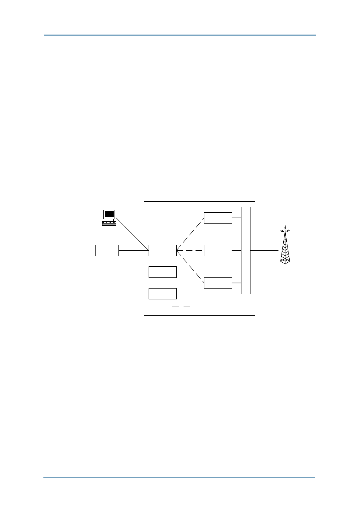
The ZXG10-BTS (V2.9) system includes the controller & maintenance unit,
base band processor (BBP), RF unit, antenna feeder processor and power
distribution unit.
Baseband
Modulated S ignal
RF Demodulation
Signal
Control Si gnal
System Clock
Antenna Feeder Process or
RF Unit
RF Signal
Um Int erface
In the downlink direction, the BTS receives the data from BSC, including
voice and signaling data. Here, the signaling data are sent to the control,
operation & maintenance unit for processing. The voice data are first sent
to the base band processor for processing such as rate conversion,
encryption and interleaving, sent to the RF unit to be modulated to highfrequency signals, and then finally transmitted via the antenna feeder
processor.
Confidential and Proprietary Information of ZTE CORPORATION 5
Page 22
ZXG10-BTS (V2.9) Technical Manual
In the uplink direction, the antenna feeder processor receives RF signals
from MS, and sends them to the RF unit to convert them into digital
signals. Then, the signals are sent to the base band processor for rate
conversion, decryption and de-interleaving. Finally, after being converted
to the code pattern suitable for long-distance transmission, the signals are
sent to BSC through the Abis interface.
Hardware Architecture
The ZXG10-BTS (V2.9) consists of the controller & maintenance module
(CMM), transceiver module (TRM), antenna feeder equipment module
(AEM), fan control modules (FCM)and power distribution module (PDM).
The hardware architecture of the ZXG10-BTS (V2.9) is shown in Figure 3.
FIGURE 3 HARDWARE ARCHITECTURE OF ZXG10-BTS (V2.9)
ZXG10-BTS(V2)
MMI
Abis
BSC
Interface
CMM
PDM
FCM
Internal Communication Bus
TRM1
TRM2
.
.
.
TRM12
A
E
M
Um
Interface
The main functions of each module are as follows:
1. CMM
CMM implements Abis interface processing, BTS operation &
maintenance, clock synchronization and generation, internal/external
alarm collection and processing and other functions.
2. TRM
TRM controls and processes the radio channels; transmits and receives
the radio channel data; modulates and demodulates the baseband
signals on the radio carrier; and transmits and receives radio carriers
in the GSM system.
The TRM is divided into three units by function:
i. Transceiver Processing Unit (TPU)
6 Confidential and Proprietary Information of ZTE CORPORATION
Page 23

Chapter 1 - System Architecture
The TPU implements all functions of baseband data processing of all
full-duplex channels on a TDMA frame, and the conversion between
LapDm protocol and LapD protocol. It supports GPRS packet data
service functions, CS1, CS2, CS3, CS4 coding modes, MCS1, MCS2,
MCS3, MCS4, MCS5, MCS6, MCS7, MCS8 and MCS9 coding modes,
and 8PSK modulation modes.
ii. Radio Carrier Unit (RCU)
RCU modulates baseband signals to carrier signals and up-converts
frequency. At the same time, it down-converts the frequency of
received carrier signals. In addition, it can control the power
statically and dynamically in the downlink direction as required in
GSM specifications.
iii. Power Amplifier Unit (PAU)
PAU amplifies the power of the radio carrier to provide the BS
equipment with sufficient transmission power.
3. AEM
AEM implements the combination/distribution of air signals. It is
composed of three types of combiner/distribution units.
i. Combiner Distribution Unit (CDU)
CDU supports one 2-in-1 combiner unit and one 1-to-4 distribution
unit. It has two low noise amplifiers with extended receiving output
and one built-in duplexer.
ii. Receiver Distribution Unit (RDU)
RDU supports one 1-to-4 distribution unit and has two low-noise
amplifiers with extended receiving output and one receiving filter.
iii. Combiner Extension Unit (CEU)
CEU supports two 1-to-2 power distribution units and two 2-in-1
combiner units.
Through the combination of CDU, RDU and CEU, AEM provides
various site configurations for ZXG10-BTS (V2.9).
4. FCM
In the thermal design of the ZXG10-BTS (V2.9), one fan layer with two
fans is installed on each carrier shelf to ensure the system to work
normally since the carrier shelf is the major heat source.
FCM collects and monitors the temperature in the carrier shelf and use
the fans to dissipate the heat out of the cabinet.
5. PDM
PDM distributes the DC power supply (-48 V) to the modules, and
provides overload open-circuit protection and filtering of the basic
power input.
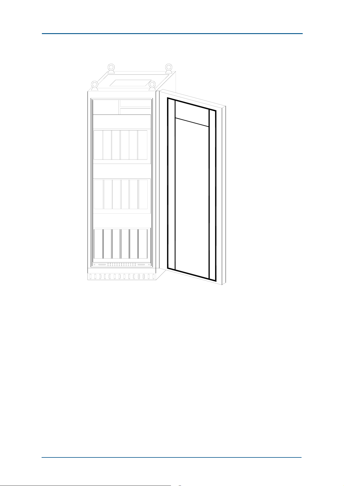
Figure 4 shows the positions of modules in a fully configured 40 W
single cabinet.
Confidential and Proprietary Information of ZTE CORPORATION 7
Page 24
ZXG10-BTS (V2.9) Technical Manual
FIGURE 4 SINGLE CABIN ET (40 W) IN FULL CONFIGURATION
P D M
A
E
M
A
E
M
A
E
M
C M M
C M M
T
T
T
T
R
R
M/
M/
E
E
T
T
R
R
M
M
T
T
R
R
M/
M/
E
E
T
T
R
R
M
M
T
T
R
R
M/
M/
E
E
T
T
R
R
M
M
R
R
M/
E
T
R
M
T
R
M/
E
T
R
M
T
R
M/
E
T
R
M
A
M/
E
E
T
M
R
M
635421
T
R
A
M/
E
E
T
M
R
M
612345
T
R
A
M/
E
E
T
M
R
M
635421
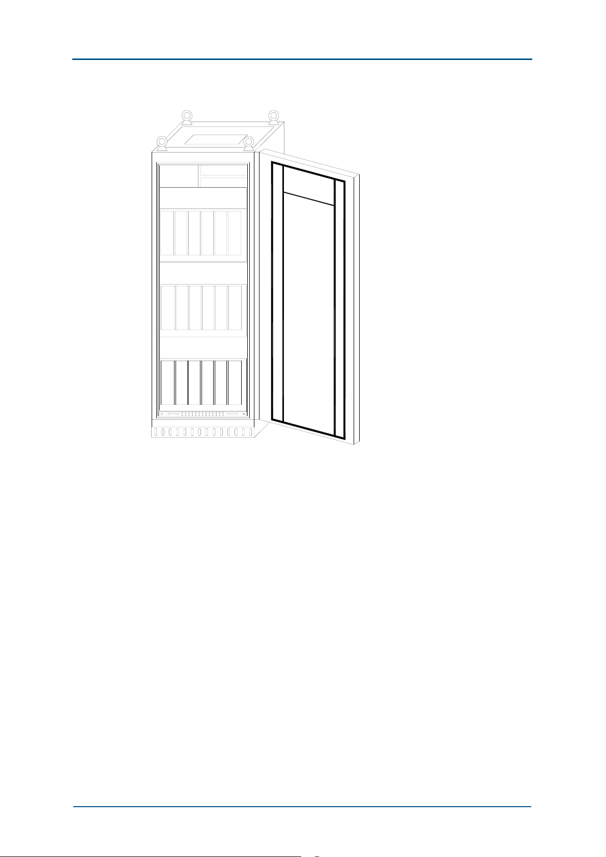
Figure 5 shows a fully configured 80 W single cabinet with TRM modules
consisting of two types of modules: STRU and SPA.
8 Confidential and Proprietary Information of ZTE CORPORATION
Page 25
Chapter 1 - System Architecture
FIGURE 5 SINGLE CABIN ET (80 W) IN FULL CONFIGURATION
P D M
A
E
M
1
A
E
M
A
E
M
C M M
C M M
S
S
S
S
P
T
A
R
G
G
S
S
T
P
R
A
G
G
23 45 61
S
S
P
T
A
R
G
G
A
P
T
E
A
R
M
G
G
5623 4
S
S
A
P
T
E
A
R
M
G
G
S
S
A
P
T
E
A
R
M
G
G
5 623 41
Software Architecture
In software design, the ZXG10-BTS (V2.9) adopts modular and
hierarchical concepts to facilitate future development and maintenance.
The software is distributed on boards.
There is little correlation between various software. The board software is
independent in function and associates with each other through the
internal interfaces.
The core software can be downloaded from the background, facilitating
service upgrade and version maintenance. It also provides external
interfaces, through which the software can be maintained, BTS information
can be collected, and BTS local tests can be performed.
The internal software of ZXG10-BTS (V2.9) is divided into four parts: CMM
(Controller & Maintenance Module), FUC (Frame Unit Controller), CHP
(Channel Codec Module) and CIP (Carrier Interface Processor).
Confidential and Proprietary Information of ZTE CORPORATION 9
Page 26

ZXG10-BTS (V2.9) Technical Manual
Different software platforms are adopted for the software according to
their functions, as shown in Figure 6.
FIGURE 6 SOFTWARE COMPOSITION AND MODULE DIVISION OF ZXG10-BTS (V2.9)
CMM
Software
System
FUC
CHP
CIP
Controller & Maintenance Module (CMM)
CMM is the control & maintenance module of the ZXG10-BTS (V2.9).
Its main functions are as follows:
BTS status management.
BTS configuration management
BTS equipment management
BTS monitoring management
BTS test management
BTS database management
Supporting local operation and management (O&M) function, including
local parameter configurations and alarm query
The CMM software is designed in layers, as shown in Figure 7.
10 Confidential and Proprietary Information of ZTE CORPORATION
Page 27
Chapter 1 - System Architecture
FIGURE 7 MODULE S TRUCTURE OF CMM SOFTWARE
APP
LMU
DBS
OSS
RUNCTRL
RUNSPT
PSOS+
BSP
O&M
LNKCTRL
LNKDRV
Hardware
The whole CMM software is divided into five layers,
1. Hardware
The physical platform on which the CMM software is running.
2. BSP (board-level support package)
BSP initializes CMM boards and provides drivers for the relevant parts
of the equipment. It provides consistent operation interfaces for the
specific details of the upper-level encapsulated hardware equipment
and simplifies the OSS design.
3. pSOS + operating system
It is a real-time multi-task operating system for commercial purposes
and with superior performance. The operating system has been
successfully applied to the next-generation BTS.
4. Operation support system (OSS) layer
in particular:
i. RUNSPT
It is the core layer of the OSS.
It is a dispatch system of the state machine, providing process
dispatch, process communication, memory management, timer
management, process monitoring and exceptional capture.
ii. RUNCTRL
It is the operation control layer of the system.
Confidential and Proprietary Information of ZTE CORPORATION 11
Page 28

ZXG10-BTS (V2.9) Technical Manual
It includes the system control module and implements the poweron sequence for application processes. In addition, this layer
includes some miscellaneous functions of the operating system
such as redirection of the printing messages.
iii. LNKDRV
It is the device driver.
Working with BSP, LNKDRV provides equipment-independent
drivers for LNKCTR. At the same time, this part also includes a
frame number synchronization module, implementing the frame
number synchronization between active/standby CMMs, active
CMMs of the master rack and the secondary rack, and master CMM
and TRMs.
iv. LNKCTRL
It is the communication link control layer module.
It consists of multiple communication link control modules, like
LapD, HDLC, LMComm.
LapD communication link control module
LapD is the communication link control module of the Abis interface.
HDLC communication link control module
HDLC is the communication link control module inside the rack.
They all communicate in a point-to-point way.
There are three types of communication links: CCComm, CMComm
and CTComm.
CCComm: The CCComm is the auxiliary communication link
between the master CMM of the master rack and that of the slave
rack. Physically, it is a 2 M PCM line, which facilitates the
centralized data collection of LMU.
CMComm: As the communication link between the active CMM and
the standby CMM, it implements the data synchronization between
the active CMM and standby CMM. Physically, it uses 1 M HW.
CTComm: As the communication link between the active CMM and
1 ~ 12 TRMs of its racks, the CTComm implements the parameter
configuration of TRM and alarm collection. Physically, it uses a 64
Kbit/s timeslot in 4 M HW.
LMComm
Foreground/background link control module with RS232 as its
physical interface. It is a self-defined point-to-point link control
protocol and character-oriented single-bit stop and wait protocol.
5. APP layer:
It is the application layer, consisting of three parts:
i. O&M
As the core of the application layer, it receives the O&M messages
of the Abis interface and implements parameter configuration,
status and alarm management, software version management,
equipment test and external alarm collection.
12 Confidential and Proprietary Information of ZTE CORPORATION
Page 29

Chapter 1 - System Architecture
ii. DBS
The whole application layer is designed with the database as a core.
The database coordinates to assign configuration parameters and
also synchronizes data between the active and standby CMMs and
the foreground and background.
iii. LMU
It is the local O&M unit, including two parts: foreground agent and
background operation interface.
It works with the database synchronization module to complete the
local parameter configuration, equipment status and alarm
collection. It also includes operating interface of equipment test to
implement test functions of the local BTS.
The system tool part is a series of developer-oriented tools for
system diagnosis and test to rapidly locate faults.
FUC
FUC (Frame Unit Controller)
The FUC software module is located in the TPU of the TRM module. It
processes the radio signaling over every radio carrier and signaling on the
BSC interface and manages all channels. Its major functions are as follows:
1. Responsible for processing and converting GSM signaling protocols,
including the layer-2 protocol LAPD with BSC, the layer-2 protocol
HDLC with CMM, the layer-2 protocol LAPDm with the Um interface and
the layer-3 radio resources management protocol of GSM.
2. Responsible for the TDMA multi-frame framing on the Um interface,
frame number (FN) receiving, frequency hopping calculation and
management & control over CHP.
3. It also manages BTS and loads the FUC software and DCP program. It
supports global packet switching services (GPRS or PS for short).
The whole FUC software can be divided into two layers: system
software and application, as shown in Figure 8.
Confidential and Proprietary Information of ZTE CORPORATION 13
Page 30
ZXG10-BTS (V2.9) Technical Manual
FIGURE 8 FUC SOFTWARE MODULE STRUCTURE
APP
OAMM
RUNCTRL
RUNSPT
RSM
OSS
LNKCTR
LNKDR
PSOS+
BSP
LMA
Hardware
The concept of virtual operating system is adopted for the system software.
Based on the commercial operating system pSOS+, the running support
layer RUNSPT of the limited state machine is oriented to make the
application irrelevant with the actual real-time operating system, simplify
the application implementation and improve the application grafting.
RUNCTRL implements the power-on boot sequence of system’s modules
and some auxiliary functions of the operating system. It collects and
redirects the output messages.
The drivers are also designed with a hierarchical structure, including
equipment-dependent and equipment-independent drivers. All
communications within the current equipment adopt the address transfer
mode to reduce the overhead of the memory block copies.
The application layer contains the operation and maintenance module
(OAMM), radio signaling processing module (RSM) and local O&M agent
module (LMA).The OAMM configures and manages the software,
parameters, status and alarms of the TPU board. The RSM can be divided
into the FURRM (Radio Resource Management Module), PAGCHM (Paging
Access Channel Message Processing Module) and FHM (Frequency Hopping
Module).These modules implement the signaling flows of circuit switched
service and packet switched service according to the GSM protocol, and
they support frequency hopping. LMA is used in system debugging.
CHP
CHP (Channel Codec Module)
The CHP software module is located in the TPU of the TRM in the system.
14 Confidential and Proprietary Information of ZTE CORPORATION
Page 31

Chapter 1 - System Architecture
It implements all baseband channel processing and some corresponding
control functions, including channel encoding, channel decoding and
demodulation.
CIP
CIP (Carrier Interface Unit)
The CIP software module is located in the TPU of the TRM in the system.
The functions of CIP software are GMSK (GSM modulation mode), 8PSK
(EDGE modulation mode), software modulation, power control and the
collection and handling of AEM, amplifier, RCU and fan alarm information.
System Features
The ZXG10-BTS (V2.9) has the following features:
1. High jumping-off point in technology
The ZXG10 BTS (V2.9) starts from the new generation of GSM
technology, and the standards of GSM Phase II are adopted. It can be
upgraded to GSM Phase II+ smoothly.
2. Advanced functions, complete services and flexible configuration
It meets GSM specification requirements, and can be configured as
required by users.
It supports GPRS/EDGE data service functions and AMR voice service.
It supports multiple bands, mixed insertion of modules of different
bands, and mixed insertion of modules of different services.
It supports 40 W and 80 W configurations.
Frequency hopping is supported.
3. Large capacity
A single rack supports a maximum of 12 TRXs.
Each station supports a maximum expansion of 36 TRXs.
Each station supports a maximum expansion of S12/12/12.
4. Beautiful appearance and compact structure
The ZXG10 BTS (V2.9) is designed in a rack-type modular structure
with simple appearance, compact structure, superior electromagnetic
shielding performance and good internal ventilation and heat sinking.
Both the front door and back door of the rack can be opened to
facilitate maintenance.
5. Modular design in software/hardware.
The hardware of the ZXG10 BTS (V2.9) has a modular design, making
it possible to use fewer types of boards and modules, thus enhancing
Confidential and Proprietary Information of ZTE CORPORATION 15
Page 32

ZXG10-BTS (V2.9) Technical Manual
board integration, facilitating project installation and maintenance, and
improving the reliability of the system.
6. Advanced software radio technology.
The ZXG10 BTS (V2.9) uses software radio technology to ensure the
long-term reliable operation of the RF parts and improve the batch
consistency and mass productivity of equipment.
7. Flexible and reliable Abis interface
Advanced flow control algorithms and variable rate signaling link
technology are used so that multiple logical signaling links can be
configured on the 64 Kbit/s physical link to fully share the bandwidth.
An E1 can be shared by 15 carriers (under special configuration).
When multiple BTSs are cascaded, the automatic crossover protection
function is provided for the Abis interface link when any BTS is
powered off.
8. Secure and reliable power supply system.
The primary power supply supports -48 V supply; the secondary power
supply with a distributed design is integrated in various modules,
improving the reliability of the system.
9. Perfect environment monitoring capability
Providing inputs for 10 pairs of external environment trunk nodes, and
outputs for 8 pairs of trunk nodes.
10. Good heat design
A fan layer is designed on the carrier shelf of each layer and can hold
two fans, monitoring and collecting the temperature inside the carrier
shelf, thus automatically adjusting the rotational speed of the fans.
Each layer of the carrier shelf has a separate ventilation duct, and heat
is dissipated out of the rack through the common duct of the rack.
11. Convenient local operation and maintenance
It adopts a standard RS232 interface to connect with the local
operation and maintenance terminal to spare special cables.
The local operation and maintenance terminal is easy to learn and use
since it is consistent with the OMCR interface.
Perfect local operation and maintenance
Rapid and reliable online software upgrade.
16 Confidential and Proprietary Information of ZTE CORPORATION
Page 33

Chapter 2
Technical Indices
This chapter describes the system indices and external interfaces of the
ZXG10-BTS (V2.9).
Working Band
1. Working frequency band
The ZXG10-BTS (V2.9) can support 900 MHz, extended 900 MHz, 850
MHz, 1800 MHz and 1900 MHz by being configured with different
functional modules.
i. 900 MHz band
Uplink (transmitted by MS and received by BS) frequency range:
890 MHz ~ 915 MHz
Downlink (transmitted by BS and received by MS) frequency range:
935 MHz ~ 960 MHz
ii. Extended 900 MHz band
Uplink (transmitted by MS and received by BS) frequency range:
880 MHz ~ 915 MHz
Downlink (transmitted by BS and received by MS) frequency range:
925 MHz ~ 960 MHz
iii. 850MHz band
Uplink (transmitted by MS and received by BS) frequency range:
824 MHz ∼849 MHz
Downlink (transmitted by BS and received by MS) frequency range:
869 MHz ∼894 MHz
iv. 1,800 MHz band
Uplink (transmitted by MS and received by BS) frequency range:
1,710 MHz ~ 1,785 MHz
Downlink (transmitted by BS and received by MS) frequency range:
1,805 MHz ~ 1,880 MHz
Confidential and Proprietary Information of ZTE CORPORATION 17
Page 34

ZXG10-BTS (V2.9) Technical Manual
v. 1,900 MHz band
Uplink (transmitted by MS and received by BS) frequency range:
1,805 MHz ~ 1,910 MHz
Downlink (transmitted by BS and received by MS) frequency range:
1,930 MHz ~ 1,990 MHz
2. Channel interval
The interval between two adjacent channels in any band is 200 kHz.
3. Channel configuration
All channels are configured with the same interval.
i. 900 MHz band
The channel number is in the range of 1 ~ 124. There are 124
frequency bands in all.
The relationship between the channel numbers and frequency band
nominal central frequency is illustrated as follows:
Fu (n) = 890 + 0.2 × n (MHz), uplink
Fd (n) = Fu (n) + 45 (MHz), downlink
Here, 1 ≤ n ≤ 124, n is a channel number, or an ARFCN (Absolute
Radio Frequency Channel Number).
ii. Extended 900 MHz band
The channel number is in the range of 0 ~ 124 and 975 ~ 1023.
There are 174 frequency bands in all.
The relationship between the channel numbers and frequency band
nominal central frequency is illustrated as follows:
Fu (n) = 890 + 0.2 × n (MHz), 0 ≤ n ≤ 124
Fu (n) = 890 + 0.2 × (n - 1024) (MHz), 975 ≤ n ≤ 1023
Fd (n) = Fu (n) + 45 (MHz)
iii. 850 MHz band
The channel number is in the range of 128 ~ 251. There are 124
frequency bands in all.
The relationship between the channel numbers and frequency band
nominal central frequency is illustrated as follows:
Fu (n) = 824.2 + 0.2 × (n - 128) (MHz)
Fd (n) = 869.2 + 0.2 × (n – 128) (MHz)
128 ≤ n ≤ 251
iv. 1,800 MHz band
The channel number is in the range of 512 ~ 885. There are 374
frequency bands in all.
The relationship between the channel numbers and frequency band
nominal central frequency is illustrated as follows:
Fu (n) = 1710.2 + 0.2 × (n - 512) (MHz)
18 Confidential and Proprietary Information of ZTE CORPORATION
Page 35

Chapter 2 - Technical Indices
Fd (n) = Fu (n) + 95 (MHz)
512 ≤ n ≤ 885
v. 1,900 MHz band
The channel number is in the range of 512 ~ 811. There are 300
frequency bands in all.
The relationship between the channel numbers and frequency band
nominal central frequency is illustrated as follows:
Fu (n) = 1850.2 + 0.2 × (n - 512) (MHz)
Fd (n) = Fu (n) 80 (MHz)
512 ≤ n ≤ 811
4. Duplex transceiving interval
i. 900 MHz band
The duplex transceiving interval is 45 MHz.
ii. Extended 900 MHz band
The duplex transceiving interval is 45 MHz.
iii. 850 MHz band
The duplex transceiving interval is 45 MHz.
iv. 1,800 MHz band
The duplex transceiving interval is 95 MHz.
v. 1,900 MHz band
The duplex transceiving interval is 80 MHz.
Physical Indices
Dimensions, Color and Structure
Rack dimensions (H × W × D) (excluding the base):
1,600 mm × 600 mm × 550 mm (H × W × D)
Its color is light grey (ZX-P02*02).
It is a welded-style rack with doors that can be opened to both sides.
Weight of Integrated Equipment and
Weight Bearing Requirements of
Equipment Room Ground
The maximal static weight of a single rack is 270 kg.
Confidential and Proprietary Information of ZTE CORPORATION 19
Page 36

ZXG10-BTS (V2.9) Technical Manual
The weight bearing capacity of the equipment room ground should be
1,200 kg/m
2.
Power Supply of Equipment
Voltage
Nominal working voltage: -48 VDC
Range: -57 VDC ~ -40 VDC
Power Consumption
The maximal power consumption of each module is as follows:
TRM: 160 W
TRM: 175 W
CMM: 16 W
Fan: 60 W
CDU or RDU: 5 W
The power consumption of the integrated equipment in full configuration is
less than 2,200 W.
Heat in the rack is from the TRM and AEM in the carrier plug-in shelf.
The heat consumption distribution of each module:
TRM: 120 W
ETRM: 135 W
AEM: 45 W
CMM (two): 20 W
Fan and other parts: 30 W
Under full configuration:
Without ETRM, the heat consumption of each carrier shelf, 600 W;
integrated equipment, less than 2,200 W
With ETRM, the heat consumption of each carrier shelf (fan included),
600 W; integrated equipment, less than 2,350 W
20 Confidential and Proprietary Information of ZTE CORPORATION
Page 37

Chapter 2 - Technical Indices
Environmental Conditions
Temperature and Humidity Requirements
Working temperature: -5 ºC ~ 45 ºC
Relative humidity: 10% ~ 90 %, no condensation
Grounding Requirements
The case of the rack should be grounded well, with the grounding
resistance less than 5 ohm.
Atmospheric Pressure Requirements
1.08 × 10⁵ pa ~ 5.1 × 10⁴ pa (-500 mm ~ +500 mm)
Lighting
Direct sunshine should be avoided to prevent the circuit boards and other
components from aging and deforming. The average illumination should be
300x ~ 450lx and no glare should exist.
Air Pollution
Erosive gases, smog and smoking are prohibited in the equipment room.
Interface Indices
Abis Interface Indices
The Abis interface adopts the standard E1 interface.
The performance of the Abis interface meets the requirements specified by
ITU-T G.703 and ITU-T G.704. Details are as follows:
1. Basic requirements
i. Nominal bit rate: 2,048 Kbit/s
-6
ii. Bit rate tolerance: ± 50 × 10
iii. Signal code pattern: HDB3
2. Electrical features
i. Pulse shape: rectangular
ii. Nominal peak voltage of pulse (mark):
2.37 V (75 ohm, a pair of coaxial cables).
Confidential and Proprietary Information of ZTE CORPORATION 21
Page 38

ZXG10-BTS (V2.9) Technical Manual
3 V (120 ohm, a pair of symmetrical cables).
iii. Peak voltage when without pulse (vacant number):
0±0.237 V (75 ohm, one pair of coaxial cables).
0.3 V (120 ohm, a pair of symmetrical cables).
iv. Nominal pulse duration: 244 ns
v. The amplitude ratio between the positive pulse and the negative
pulse
The amplitude ratio of positive and negative pulses is at the
intermediate point in pulse duration: superior than 0.955 ~ 1.05
Positive and negative pulse duration ratio at half nominal pulse
amplitude: superior than 0.95 ~ 1.05
vi. Digital signal jittering features (1UI = 488ns):
1.5 UI (peak-peak value, 20 Hz ~ 100 kHz).
0.2 UI (peak-peak value, 18 Hz ~ 100 kHz).
vii. Input impedance features
Corresponding to the nominal bit rate (2,048 Kbit/s) 2.5% ~ 5%;
that is, when it is 51.2 Kbit/s ~ 102.4 Kbit/s, echo attenuation ≥
12 dB.
Corresponding to the nominal bit rate (2,048 Kbit/s) 5% ~ 100%;
that is, when it is 102.4 Kbit/s ~ 2,048 Kbit/s, echo attenuation ≥
18 dB.
Corresponding to the nominal bit rate (2,048 Kbit/s) 100% ~ 150%;
that is, when it is 2,048 Kbit/s ~ 3072 Kbit/s, echo attenuation ≥
14 dB.
Um Interface Indices
Main indices are as follows:
1. Wireless channel
Co-channel interference protection ratio C/I ≥ 9 dB (static).
Interference protection ratio of the adjacent channels ≥ - 9 dB
Interference protection ratio the second adjacent channel ≥ -43 dB
The wireless channel selection adopts the shared signaling channel
mode.
2. Wireless RF modulation mode
It adopts gauss minimal shift keying (GMSK) to perform modulation.
BT = 0.3 and the modulation coefficient is 1.35.
3. Performance of the transmitter
i. Phase error of the transmitter
The phase error of the transmitter is the error between the actual
phase and the theoretical one.
22 Confidential and Proprietary Information of ZTE CORPORATION
Page 39

Chapter 2 - Technical Indices
The root mean square of the BS phase error is not greater than
5°and the peak value is not over 20°.
ii. Frequency error of the transmitter
The frequency error of the transmitter is the error between the
actual frequency and the theoretical one.
The BS frequency error is not over 0.05 ppm.
iii. Average transmitted carrier power (requirement for the power
amplifier output)
40 W or 80 W.
It is provided with the 6-level static power control function. Based
on the maximum output power, it can adjust downwards 6 power
levels with the step of 2dB ± 1.0dB. At the same time, BS has the
downlink power control function. Based on the set power level, it
can decrease the power from level zero to level-15 with the step of
2dB ± 1.5dB.
iv. Transmitted RF carrier power/time envelop
Compliant with GSM 11.21 and GSM 05.05.
v. The inter-modulation attenuation of the transmitter
Compliant with GSM 11.21 and GSM 05.05.
vi. The inter-modulation attenuation in BSS
Compliant with GSM 11.21 and GSM 05.05.
vii. Transmitted adjacent channel power
Compliant with GSM 11.21 and GSM 05.05.
viii. Spurious emission of the transmitter
Compliant with GSM 11.21 and GSM 05.05.
4. Performance of the transmitter
i. The static layer-1 function of the transmitter (nominal error rate)
The static first layer functions of the receiver are the floorboard of
such functions of RF part, multiplexing and multi-addressing,
equalizer de-encryption, de-interleaving and the channel encoding.
The static layer-1 function is signified by the nominal error rate (bit
error rate (BER)) before channel decoding.
Compliant with GSM 11.21 and GSM 05.05.
ii. Static referential sensitivity level
The static referential sensitivity level means that when inputting a
standard test signal under the static environment, the FER, RBER
or BER performance of the data, generated after modulation and
channel decoding, meets the specified requirements when the level
is configured as the referential sensitivity level.
Compliant with GSM 11.21 and GSM 05.05.
iii. Multi-path referential sensitivity
Confidential and Proprietary Information of ZTE CORPORATION 23
Page 40

ZXG10-BTS (V2.9) Technical Manual
A standard testing signal is inputted in the multi-path environment.
When the level is set as the reference sensitivity level, the data
generated after modulation and channel encoding have the FER,
RBER or BER performance that can satisfy the requirements
specified.
Compliant with GSM 11.21 and GSM 05.05.
iv. Referential interference level (interference and suppression of the
same frequency and adjacent channels).
The referential interference level means the capability that the
transmitter receives the expected modulation signal not over the
given degraded quantity, which is caused by the unexpected
modulation signal on the same carrier frequency (inference of the
same channel) or any adjacent carrier frequency (inference of the
adjacent channel).
Compliant with GSM 11.21 and GSM 05.05.
v. Block and spurious response suppression
The block and spurious response suppression is to test the
capability that the BSS transmitter receives the GSM modulation
signal when interferential signal exists.
Compliant with GSM 11.21 and GSM 05.05.
vi. Inter-modulation suppression
This index is for measuring the linear degree of the RF part of the
transmitter. It indicates, when two or multiple unexpected signals
which are relative to the expected signal in frequency exist, the
transmitter’s capability of receiving the respected modulation signal
is not over the given degraded quantity.
Compliant with GSM 11.21 and GSM 05.05.
vii. AM suppression
AM suppression means the transmitter’s capability of receiving the
expected modulation signals is not over the given degraded
quantity when an unexpected modulation signal exists.
Compliant with GSM 11.21 and GSM 05.05.
viii. Spurious emission
The spurious emission is the emission on the frequencies except
that of the RF channel of the transmitter and adjacent frequencies.
Compliant with GSM 11.21 and GSM 05.05.
Capacity Indices
A single rack holds twelve 40 W carriers or six 80 W carriers when
configured to the full capacity.
A site supports three racks, thirty-six 40 W carriers or eighteen 80 W
carriers at most.
24 Confidential and Proprietary Information of ZTE CORPORATION
Page 41

Chapter 2 - Technical Indices
Clock Indices
It provides a two-level clock, whose indices are as follows:
-9
Clock accuracy: ±1.0×10
Pull in range: ±1.0×10
Maximum frequency bias: 1 × 10
Initial maximum frequency bias: 1×10
-9
-9
/day
-7
Reliability Indices
MTBF (Mean Time Between Failure) (hour): 6.3 ~ 104 hours
Mean Time To Repairs (MTTR): 0.57 hours
Availability ratio A (%): 99.9991%
Annual average interruption time of the system (hour): 0.080 hours
The product successfully passed the CE certification. The personal safety,
electromagnetic security, EMC and guarantee of the wireless frequency
spectrum comply with international standards.
Confidential and Proprietary Information of ZTE CORPORATION 25
Page 42

ZXG10-BTS (V2.9) Technical Manual
This page is intentionally blank.
26 Confidential and Proprietary Information of ZTE CORPORATION
Page 43

Chapter 3
Interfaces and
Communications
This chapter details different external interfaces of the ZXG10-BTS (V2.9)
and different interface protocols.
Overview
Figure 9. Illustrates the positions of the main interfaces of the ZXG10BTS(V2.9)in the system.
FIGURE 9 EXTERNAL INTERFACE POSITIONS OF ZXG10-BTS (V2.9)
M Interface
Moni t or ing
Ext er nal
System
MS MS
Abis Interface
B Interface
BTS BTSBSC
MMI Interface
LMT
Um Interface
Tower Amplifier
System Interface
Amplifier
System
Tower
Apart from the Abis and Um interfaces, the ZXG10-BTS (V2.9) has the
cascaded interface (B interface) between BTSs, interface (M interface) with
Confidential and Proprietary Information of ZTE CORPORATION 27
Page 44

ZXG10-BTS (V2.9) Technical Manual
the external environment monitoring system, interface of the tower
amplifier system and the local O&M interface.
The Abis interface is a communication interface between BTS and BSC.
The Um interface is the interface between BTS and MS. The B interface is
actually an extension of the Abis interface. The M interface between BTS
and the monitoring system of the external environment provides a
transparent path for the O&M of the ZXG10-BTS (V2.9).The tower
amplifier system provides the power supply and the alarm interfaces. The
man-machine interface (MMI) is an interface between the local O&M
terminal (LMT) and BTS.
Interfaces
Abis Interface
The Abis interface is defined as an interface between BSC and BTS.
The Abis interface sends the signal from the BSC to the BTS, usually the
standard E1 signal of PCM 2M.The unbalanced input mode of 75 ohm
coaxial cable is adopted for it to implement access through the
transmission equipment digital microwave, fiber transmission (SDH and
PDH) and satellite link.
Physically, an E1 interface is adopted as the Abis interface, and it is
connected with the thin coaxial cable & D-socket.
Protocols on the Abis interface are hierarchical, and the protocol hierarchy
of circuit service is shown in Figure 10. The Abis interface does not process
the packet service protocol, and it is transparent for the packet signaling.
FIGURE 10 C IRCUIT SERVICE P ROTOCOL LAYERED STRUCTURE OF ABIS INTERFACE
Abis Interface
RR
BTSM
LAPD
Sig.L1
BTSM
LAPD
Sig.L2
BTS
BSC
On the Abis interface, the circuit service protocols fall into three layers:
28 Confidential and Proprietary Information of ZTE CORPORATION
Page 45

Chapter 3 - Interfaces and Communications
1. Layer-1 (physical layer) is the PCM digital link at the rate of 2,048
Kbit/s.
2. Layer-2 (data link layer) is based on the LAPD.
3. Layer-3 transparently transmits the layer-3 messages on the A
interface and manages radio resources.
The protocols related to the Abis interface are as follows:
GSM 08.52 presents the basic principles and rules of other specifications
for the Abis interface and how the service functions are divided between
BSC and BTS.
GSM 08.54 specifies the physical structure of the Abis interface.
GSM 08.56 specifies the data link layer protocol for the Abis interface.
GSM08.58 stipulates the layer-3 protocols of the Abis interface.
GSM 12.21 specifies the O&M message transmission mechanism on the
Abis interface.
Confidential and Proprietary Information of ZTE CORPORATION 29
Page 46

ZXG10-BTS (V2.9) Technical Manual
The data format of Abis interface can be flexibly configured. Configuration
examples of the Abis interface are shown in Figure 11.
FIGURE 11 T IMESLOT CONFIGURATION EXAMPLES OF ABIS I NTERFACE
0 1 2 3 4 5 6 7 0 1 2 3 4 5 6 7
TS0
SYNC TS0 SYNC
TS1 TCH0 TCH1 TCH2 TCH3 TS1 TCH0 TCH1 TCH2 TCH3
TS2 TCH4 TCH5 TCH6 TCH7 TS2 TCH4 TCH5 TCH6 TCH7
TS3 TCH0 TCH1 TCH2 TCH3 TS3 TCH0 TCH1 TCH2 TCH3
TS4 TCH4 TCH5 TCH6 TCH7 TS4 TCH4 TCH5 TCH6 TCH7
TS5 TCH0 TCH1 TCH2 TCH3 TS5 TCH0 TCH1 TCH2 TCH3
TS6 TCH4 TCH5 TCH6 TCH7 TS6 TCH4 TCH5 TCH6 TCH7
TS7 TCH0 TCH1 TCH2 TCH3 TS7 TCH0 TCH1 TCH2 TCH3
TS8 TCH4 TCH5 TCH6 TCH7 TS8 TCH4 TCH5 TCH6 TCH7
TS9 TCH0 TCH1 TCH2 TCH3 TS9 TCH0 TCH1 TCH2 TCH3
TS10 TCH4 TCH5 TCH6 TCH7 TS10 TCH4 TCH5 TCH6 TCH7
TS11 TCH0 TCH1 TCH2 TCH3 TS11 TCH0 TCH1 TCH2 TCH3
TS12 TCH4 TCH5 TCH6 TCH7 TS12 TCH4 TCH5 TCH6 TCH7
TS13 TCH0 TCH1 TCH2 TCH3 TS13 TCH0 TCH1 TCH2 TCH3
TS14 TCH4 TCH5 TCH6 TCH7 TS14 TCH4 TCH5 TCH6 TCH7
TS15 TCH0 TCH1 TCH2 TCH3 TS15 TCH0 TCH1 TCH2 TCH3
TS16 TCH4 TCH5 TCH6 TCH7 TS16 TCH4 TCH5 TCH6 TCH7
TS17 TCH0 TCH1 TCH2 TCH3 TS17 TCH0 TCH1 TCH2 TCH3
TS18 TCH4 TCH5 TCH6 TCH7 TS18 TCH4 TCH5 TCH6 TCH7
TS19 FUL TS19 TCH0 TCH1 TCH2 TCH3
TS20 FUL TS20 TCH4 TCH5 TCH6 TCH7
TS21 FUL TS21 TCH0 TCH1 TCH2 TCH3
TS22 FUL TS22 TCH4 TCH5 TCH6 TCH7
TS23 FUL TS23 TCH0 TCH1 TCH2 TCH3
TS24 EAM3 TS24 TCH4 TCH5 TCH6 TCH7
TS25 EAM2 TS25 FUL
TS26 EAM1 TS26 FUL
TS27 EAM0 TS27 FUL
TS28 O&M3 TS28 FUL
TS29 O&M2 TS29 FUL
TS30 O&M1 TS30 FUL
TS31 O&M0 TS31 FUL
An O&M timeslot on the Abis interface is multiplexed in each site, and the
O&M signaling at different sites occupies the fixed timeslot on the Abis
interface. At initialization, the OMM reads the ID signal from the rack top,
and specifies the timeslot of the BS O&M information in the Abis interface
according to the ID. For the ID description, refer to ZXG10-BTS (V2.9)
Base Transceiver Station Hardware Manual.
30 Confidential and Proprietary Information of ZTE CORPORATION
Page 47

Chapter 3 - Interfaces and Communications
For example, the site that is directly connected to BSC occupies the TS 30
Link A for O&M signaling, while the level-1 cascaded site occupies the TS
28 Link A for O&M signaling. The rest may be deduced by analogy. If the
previous-level faulty E1 interface is bridged, the next-level site can identify
the O&M channel corresponding to the site. The level of the site can be
read out on the DIP switch on the CMM board.
The Abis interface is provided with four timeslots: TRM service timeslot
TCH, TRM signaling timeslot FUL, O&M timeslot and the environment
monitoring transparent channel EAM.
The Abis interface processing is as follows:
1. Transparently transmit the TCH, FUL, O&M and EAM between cascaded
sites.
2. In the downlink direction in the same site, the service TCH and
signaling FUL are transparently transmitted to each TRM. The Q&M will
be transparently switched to the QMC interface of CMM in each rack.
The CMM will identify the O&M signaling according to TEI. EAM will be
transparently transmitted by the main rack.
3. In the uplink direction in the same site, the service TCH is transmitted
transparently, the TRM signaling FUL in the same rack is compressed
and packed in the CMM, the O&M timeslot is multiplexed based on TEI,
and the EAM timeslot is transmitted transparently in the master rack.
Um Interface
The Um interface is the interface between BTS to MS, an important
external interface of the BTS.
In the PLMN, MS connects the fixed part of the network via a radio channel
to enable subscribers to access communication services.
To interconnect the MS and BTS, a series of stipulations are provided for
signal transmission over the radio channel, and a set of standards is set up.
This set of specifications about signal transmission over radio channel is
the Um interface.
The Ums interface is designed with a hierarchical model. The circuit
service protocol hierarchy is shown in Figure 12, and the packet service
protocol hierarchy is shown in Figure 13. The packet service protocol is
implemented at the BSC side, and only physical layer is discussed here.
Confidential and Proprietary Information of ZTE CORPORATION 31
Page 48

ZXG10-BTS (V2.9) Technical Manual
FIGURE 12 C IRCUIT SERVICE P ROTOCOL HIERARCHY OF THE UM INTERFACE
CM
MM
Um Interface
RR
LAPDm
Sig.L1 Sig.L1
MS
RR
LAPDm
BTS
FIGURE 13 P ACKET SERVICE PROTOCOL STACK STRUCTURE OF THE UM INTERFACE
MS
application
IP/X.25
SNDCP
LLC
RLC
MAC
GSM RF
BSS SGSN
relay
RLC
MAC
GSM RF
BSSGP
Network
Service
L1bis
relay
SNDCP
LLC
BSSGP
Network
Service
L1bis
Um
Gb
On the Um interface, the circuit service protocols fall into three layers:
The first layer is the physical layer and also the underlying layer. It
consists of various channels and provides the basic wireless channels for
upper-level message transmission.
The second layer is the data link layer and also the medium layer, with the
LapDm adopted. It comprises various data transmission structures and
controls data transmission.
The third layer (L3) is the highest layer. It comprises various messages
and programs and provides service control.L3 consists of three sub-layers:
radio resource management (RR), mobility management (MM) and
connection management (CM).
The relevant protocols of the Um interface are as follows:
32 Confidential and Proprietary Information of ZTE CORPORATION
Page 49

Chapter 3 - Interfaces and Communications
GSM 04.03 describes the channel structure and access capability of the
Um interface.
GSM 04.04 specifies the physical layer structure of the Um interface.
GSM 04.05 specifies the data link layer protocol for the Um interface.
GSM 04.08 stipulates the layer-3 protocols of the Um interface.
Inter-Rack Cascaded Interface of Same
Site
The inter-rack star connection is supported at the same site (one site
supports three BTS racks at most).
The data interface between racks also employs the standard PCM 2M E1
signal to transfer service, TRM signaling, inter-rack O&M signaling and FN
(Frame Number).Service signaling and TRM signaling will be transparently
transmitted, while O&M and FN will be transmitted via the time division
HDLC link.
The inter-rack data interface format is shown in Figure 14.
FIGURE 14 I NTER-RACK DATA INTERFACES INSIDE A SITE
Inter-rack Downlink Interface Inter-rack Uplink Interface
0 1 2 3 4 5 6 7 0 1 2 3 4 5 6 7
TS0 SYNC TS0 SYNC
TS1 CC_COM TS1 CC_COM
TS2 FN TS2 The same as Abis interface
TS3 FN
TS4 The same as Abis interface
TS5 The same as Abis interface
TS6 The same as Abis interface
TS7 The same as Abis interface
.
.
.
TS15 The same as Abis interface TS15 The same as Abis interface
TS16 The same as Abis interface TS16 The same as Abis interface
TS17 The same as Abis interface TS17 The same as Abis interface
TS18 The same as Abis interface TS18 The same as Abis interface
.
.
.
TS31 O&M timeslot TS31 O&M timeslot
TS14 The same as Abis interface
.
.
.
.
.
.
.
.
.
Confidential and Proprietary Information of ZTE CORPORATION 33
Page 50

ZXG10-BTS (V2.9) Technical Manual
After CMM is powered on, it reads the ID signal to locate the position of
the O&M TS. The master rack generates and outputs FN and SYNCLK while
the slave rack receives them. The rack category is read by the CMM from
the rack top ID signal.
The inter-rack FN will be transmitted and broadcasted via the HDLC
protocol, the inter-rack O&M TS via the HDLC protocol and inter-rack
communication (CC_COM) via the HDLC protocol. Details are introduced as
follows:
In the downlink direction, the CMM will transparently switch the O&M
timeslot of the Abis interface to the processor of this board and other
racks of the same site. The CMM will identify the O&M according to TEI.
In the uplink direction, CMM compresses the O&M TSs of this rack and the
next rack to send to the upper-level CMM. Thus, the master rack
compresses the O&M messages of three racks into one O&M message for
reporting to the BSC.
Interface with External Environment
Monitoring System
The external environment monitoring equipment provides two types of
interfaces: One is in the serial port communication mode based on RS232,
and the other is in the communication mode that directly reflects the
alarm status in the backbone node mode.
The DB25 pin socket is adopted at the rack top of the ZXG10-BTS (V2.9)
to access the backbone node alarm status signal. The CMM can collect 10
pairs of backbone nodes for input and provide two pairs of backbone nodes
for output in the ZXG10-BTS (V2.9).
In addition, it provides one RS232 interface at the top of the ZXG10-BTS
(V2.9), which acts as an EAM transparent path to BSC for external
environment monitoring equipment.
Interfaces of Tower Amplifier System
During installation of the tower amplifier for BTS, the interfaces of the
tower amplifier system should be reserved, including the tower amplifier
power interface and the tower amplifier alarm interface. In general, they
are interfaces for providing the DC feed and alarm monitoring, and the
alarm is detected from the DC current.
BTS can provide +12 V power supply and up to 300 mA current for the
tower amplifier system via the power interface.
The tower amplifier alarm is accessed to the backbone node in the BTS
through the backbone node alarm mode, and it is monitored by the BTS.
When two lines of the backbone node in BTS are connected or connected
at a low resistance, it indicates there is alarm output for the tower
amplifier, and Alarm is ON. When two lines of the backbone node in BTS
34 Confidential and Proprietary Information of ZTE CORPORATION
Page 51

Chapter 3 - Interfaces and Communications
are not connected or connected at a high resistance, it indicates there is
no alarm output for the tower amplifier, and Alarm is OFF.
The tower amplifier power interface is located on the rack top, and one
BTS rack can provide 3 tower amplifier power interfaces.
Man-Machine Interface (MMI)
The MMI is a serial communication interface between the BTS and local
O&M terminal.
It is realized by the 10-BaseT network interface or RS 232 interface
between the CMM and local O&M terminal.
It can be connected to the serial interface of a local O&M terminal
computer or network interface through the ETP interface of the CMM panel.
Protocol Overview
For the ZXG10-BTS (V2.9), there are two important external interfaces:
Abis interface and Um interface.
The LapD, LapDm and RR/MM/CM protocols are processed on the two
interfaces. The three protocols are discussed in light of the actual system
conditions.
Um Interface Physical Layer
Timeslot
The multiple access technology enables several subscribers to share one
channel. It consists of FDMA (Frequency Division Multiple Access), TDMA
(Time Division Multiple Access) and CDMA (Code Division Multiple Access).
In the GSM system, the air interface employs a mix of FDMA and TDMA
technologies. The interval of the carrier channels is 200 kHz. A carrier is
divided into eight timeslots. Each TS, 15/26ms (about 577µs), serves as a
channel, so a carrier supports eight mobile subscribers at the same time.
Figure 15 shows a channel in the GSM system in terms of time domain and
frequency domain.
Confidential and Proprietary Information of ZTE CORPORATION 35
Page 52

ZXG10-BTS (V2.9) Technical Manual
FIGURE 15 T IMESLOTS IN THE TIME AND FREQUENCY DOMAIN
Frequency
200kHz
012 34 5 6
15/26ms
Timeslot
78
Time
TDMA Frame Structure
In the GSM system, each carrier has eight timeslots. Eight adjacent
Timeslots form a basic unit, called a TDMA frame. Several TDMA frames
form a multi-frame, as shown in Figure 16.
FIGURE 16 S CHEMATIC DIAGRAM OF THE FRAME STRUCTURE
48
0
Frame
2046 2047
494950
24 25
1
Frames=(
BCCH
CCCH
SDCCH
3060/13 ms )
50
0
TCH
SACCH/T
FACCH
1Multiframe=26TDMA
0
1
1 Hyper Frame=2048 Super Frames=2715648 TDMA
1
1 Super Frame= 1326 TDMA Frames
0
1
0
1
Frames=120
2
2
ms 1Multiframe=51TDMA
24 25
TDMA Frame=8 BP=120/26 ms
1
0
1
3456
2
The GSM circuit service has two kinds of multi-frames: 26-frame multiframe and 51-frame multi-frame.
26-frame multi-frame: It contains 26 TDMA frames, with a period 120 ms,
used for traffic channel and associated control channel.
51-frame multi-frame: It contains 51 TDMA frames, with a period
3,060/13 ms (about 235ms), used for control channel.
36 Confidential and Proprietary Information of ZTE CORPORATION
7
Page 53

Chapter 3 - Interfaces and Communications
Multiple multiframes constitute a super frame, which is a continuous 51 ×
26 TDMA frame. The period of the super frame is 1326 TDMA frames, i.e.,
6.12s.
A hyper frame consists of 2,048 super frames and its period is 12,533.76 s.
Each period of a hyper frame contains 2,715,648 TDMA frames, that is,
the TDMA FNs (Frame Numbers) range from 0 to 2,715,647.
Compared to the 26 multi-frame and 51-frame multi-frame structures in
the circuit service, the multi-frame structure consisting of 52 TDMA frames
is introduced in the GPRS system. Mapping of logical channels on all
PDCHs (Packet Data Channels) is based on such a frame structure, as
shown in Figure 17.
FIGURE 17 S CHEMATIC DIAGRAM OF THE 52-MULTIFRAME STRUCTURE
52 M ultifra m e s
B0 B1 B2 B3TTB4 IB5 B6 B7 B8 B9 B1 0 B 1 1 I
B0 B11 BLO CK ~: ;T: Fra m e for P TC CH; I: Idle Fram e
The multiframe structure of PDCH contains 12 blocks, each consisting of
four consecutive TDMA frames. There are also two idle TDMA frames and
another two for the Packet Time advance Control CHannel (PTCCH),
making a total of 52 TDMA frames.
In the packet service, the basic composition unit of all packet logical
channels except the PRACH (Packet Random Access Channel) and
PTCCH/U is block.
In a 52 multi-frame, the occupation order of 12 blocks is like this: B0, B6,
B3, B9, B1, B7, B4, B10, B2, B8, B5 and B11.
CS Logic Channel
Channels are divided into physical channels and logic channels.
The timeslot is a basic physical channel. The logical channels are defined
differently depending on the message types transmitted between the BTS
and MS. The logical channels are mapped to the physical channels for the
purpose of transmission.
By type, the logical channels are classified into CS and PS channels. By
function, they are classified into traffic channels and control channels.
1. Traffic channel (TCH)
TCHs, which carry encoded voice signals or subscriber data, include
TCH/FS (TCH/Full Speed) and TCH/HS (TCH/Half Speed).
i. Voice TCH
Confidential and Proprietary Information of ZTE CORPORATION 37
Page 54

ZXG10-BTS (V2.9) Technical Manual
TCH/FS: The full speed speech TCH, with a total rate up to
22.8Kbit/s
TCH/HS: Half speed speech TCH, with a total rate up to 11.8Kbit/s
ii. Data TCH
TCH/F9.6: 9.6Kbit/s full-rate data traffic channel
TCH/F4.8: 4.8Kbit/s full-rate data traffic channel
TCH/H4.8: 4.8Kbit/s half-rate data traffic channel
TCH/F2.4: ≤ 2.4Kbit/s full-rate data traffic channel
TCH/H2.4: ≤ 2.4Kbit/s half-rate data traffic channel
2. Control channel (CCH)
Control channels carry signaling or synchronization data, and they can
be divided into three types: broadcasting channel, common control
channel and dedicated control channel.
i. BCH
Designed to broadcast various messages to MS, broadcasting
channel is a kind of point-to-multipoint unidirectional downlink CCH
(that is, unidirectional transmission from BS to MS), including three
kinds of channels:
FCCH: Frequency calibration channel, carrying information used in
MS frequency calibration.
SCH: Synchronization channel, carrying identification information of
MS frame synchronization and BTS (Base Transceiver Station)
BCCH: Broadcasting control channel, used to send cell information;
In every BTS, there is always a transceiver with such a channel to
broadcast system information to all MSs in this cell.
ii. Common control channel
As a point-to-multipoint bi-directional CCH, CCCH is shared by MSs
in the network. There are three types of such channels:
PCH: Paging channel, used by BTS to page MS (down channel).
RACH: Random access channel, used by MS to apply for random
network-access, that is, for dedicated control channel (up channel).
AGCH: Access granted channel, used by BTS to answer the MS
random access request, that is. to assign a dedicated control
channel or directly a TCH (down channel).
iii. Dedicated control channel
Dedicated control channel is a point-to-point bi-directional CCH. It
is allocated by the BTS to MS to fulfill point-to-point transmission
between BTS and MS.
SDCCH: Stand-alone DCCH, used to transmit channel allocation
information and other relevant information; It consists of:
SDCCH/8: Stand-alone dedicated control channel
SDCCH/4: The stand-alone dedicated control channel combined with
BCCH /CCCH
38 Confidential and Proprietary Information of ZTE CORPORATION
Page 55

Chapter 3 - Interfaces and Communications
SACCH: Slow Associated Control CHannel, working together with a
traffic channel or an SDCCH to transmit specific information in the user
information, such as power and frame adjustment control information
and measurement data; This channel can be divided into the following
types:
SACCH/TF: SACCH associated with TCH/F
SACCH/TH: SACCH associated with TCH/H
SACCH/C4: SACCH associated with SACCH/C4
SACCH/C8: SACCH associated with SACCH/C8
FACCH: Short for fast associated control channel, used in combination
with a TCH to carry the same signals as SDCCH, but FACCH will be
allocated only if no SDCCH is allocated. Connection is realized via the
frame borrowed by TCH (stolen frame) to transmit such instructions as
“handover”. FACCH comes in the following types:
FACCH/F: Fast Associated Control CHannel/Full Rate
FACCH/H: Fast Associated Control CHannel/Half Rate;
TCH/F and SACCH are generally allocated in pairs. The combination of
TCH/F and SACCH is represented as TACH/F.
3. Channel Combination
In practice, logic channels of different types are usually mapped to the
same physical channel, which is called channel combination.
Following are nine channel combinations:
i. TCHFull (Traffic CHannel Full-rate): TCH/F + FACCH/F + SACCH/TF
ii. TCHHalf (Traffic CHannel Half rate): TCH/H (0, 1) + FACCH/H (0, 1)
+ SACCH/TH (0, 1)
iii. TCHHalf2 (Traffic CHannel Half rate 1): TCH/H (0, 0) + FACCH/H (0,
1) + SACCH/TH (0, 1) + TCH/H (1, 1)
iv. SDCCH (Stand-alone Dedicated Control CHannel): SDCCH/8 (0, …,
7) + SACCH/C8 (0, …, 7)
v. MainBCCH (Main Broadcasting Control Channel): FCCH + SCH +
BCCH + CCCH
vi. BCCHCombined (Broadcasting Control CHannel Combined): FCCH +
SCH + BCCH + CCCH + SDCCH/4 (0, …, 3) + SACCH/C4 (0, …, 3)
vii. BCH (Broadcasting CHannel): FCCH + SCH + BCCH
viii. BCCHwithCBCH (Cell Broadcasting CHannel): FCCH + SCH + BCCH
+ CCCH + SDCCH/4 (0, …, 3) + SACCH/C4 (0, …, 3) + CBCH
ix. SDCCHwithCBCH (Slow Dedicated CCH): SDCCH + SACCH + CBCH
Among the above channel combinations, CCCH = PCH + RACH +
AGCH.CBCH: Only downlink channels are available, carrying cell
broadcast information and sharing the physical channel with SDCCH.
Each cell broadcasts an FCCH and an SCH. The basic combination in
the downlink direction includes an FCCH, an SCH, a BCCH and a
CCCH (PCH + AGCH), allocated strictly to TN0 of BCCH carrier
configured for a cell, as shown in Figure 18.
Confidential and Proprietary Information of ZTE CORPORATION 39
Page 56

ZXG10-BTS (V2.9) Technical Manual
FIGURE 18 S CHEMATIC DIAGRAM OF 51-FRAME CHANNEL STRUCTURE
BCCH+CCCH
(Downlink)
BCCH+CCCH
(Uplink)
8 SDCCH/8
(Downlink)
8 SDCCH/8
(Uplink)
BCCH+CCCH
+4SDCCH/4
(Downlink)
BCCH+CCCH
+4SDCCH/4
(Uplink)
SF B C
R R R R R R R R R R R R R R R R R R R R R R R R R R R R R R R
D0 D1 D2 D3 D4 D5 D6 D7 A0 A1 A2 A3
D0 D1 D2 D3 D4 D5 D6 D7 A4 A5 A6 A7 III
A1 A2 A3 III
A5 A6 A7 III
SF B C SF C C SF D0 D1 SF D2 D3 ISF A0 A1
SF B C SF C C SF D0 D1 SF D2 D3 ISF A2 A3
D3D3R R
F:FCCH S:SCH
B:BCCH C:CCCH(CCCH=PCH+AGCH+RACH)
R:RACH D:SDCCH
A:SACCH/C I:idle
R R
51 Frame
SF C C SF C C SF C C I
R R R R R R R R R R
(a) FCCH+SCH+BCCH+CCCH
D0 D1 D2 D3 D4 D5 D6 D7 A0
D0 D1 D2 D3 D4 D5 D6 D7 A4
(b) SDCCH/8(0,...,7)+SACCH/C8(0,...,7)
A2 A3
A0 A1
R R R R R R R R R R R R R R R R R R R R R R R
R R R R R R R R R R R R R R R R R R R R R R R
(c) FCCH+SCH+CCCH+SDCCH/4(0,...,3)+SACCH/C4(0,...,3)
D0 D1
D0 D1
SF C C
R R R R R R R R R R
III
D2D2SF
SF
For the half-rate voice channel combination, each timeslot has two
half-rate sub-channels and corresponding SACCH, with 26TDMA
frames as the multi-frame. The frame structure is shown in Figure
19.
FIGURE 19 S TRUCTURE OF THE HAL F-RATE V OICE CHANNEL
26 Frames
H0H
H
1
H
0
1
H0H0H
H1H
1
0
H
H1H
0
S
H
1
1
H0H
H1H
0
0
H0H
H1H1H
0
0
1
S
H
H
1
0
1
4. Channel arrangement in the cell
Given below are several examples of channel combination in a cell (in
the brackets are sub-channels).
i. Channel combination in a small-capacity cell with only one TRX
TN0: FCCH + SCH + BCCH + CCCH + SDCCH/4 (0, …, 3) +
SACCH/C4 (0, …, 3)
TN1 ~ 7: TCH/F + FACCH/F + SACCH/TF
ii. Channel combination in a medium-capacity cell with four TRXs
One TN0 group: FCCH + SCH + BCCH + CCCH
Two SDCCH/8 (0, …, 7) + SACCH/C8 (0, …, 7)
29 TCH/F + FACCH/F + SACCH/TF
iii. Channel combination in a large-capacity cell with 12 TRXs
40 Confidential and Proprietary Information of ZTE CORPORATION
Page 57

Chapter 3 - Interfaces and Communications
One TN0 group: FCCH + SCH + BCCH + CCCH
One TN2 group, one TN4 group and one TN6 group: BCCH + CCCH
Five SDCCH/8 (0, …, 7) + SACCH/C8 (0, …, 7)
87 TCH/F + FACCH/F + SACCH/TF
PS Logic Channel
By function, packet logical channels are divided into packet data
transmission channel (PDTCH) and packet control channel (PCCH).
1. PDTCH
Unlike the circuit service, all PDTCHs in the packet service are
unidirectional; that is, the up link and down link are independent of
each other.
PDTCHs include PDTCH/U (uplink) and PDTCH/D (downlink).
PDTCHs carry user data. They are allocated temporarily to a specific
MS or a group of MSs. In multi-timeslot mode, an MS can use at most
eight PDTCHs at the same time.
PDTCH/U is used by MS to send packet data to the network and
PDTCH/D is used by the MS to receive packet data from the network.
2. PCCH
PCCHs are listed in Table 4.
TABL E 4 PCCH
Name Classification
Packet random access channel (PRACH) (uplink)
PCCH
Packet Common
Control Channel
(PCCCH)
Packet Broadcast
Control Channel
(PBCCH)
Packet dedicated
control channel
Packet paging channel (PPCH) (downlink)
Packet access granted channel (PAGCH) (downlink)
Packet notification channel (PNCH) (downlink)
PBCCH (downlink)
Packet Associated Control Channel (PACCH)
Packet time lead control channel (PTCCH/U) (uplink)
Packet time lead control channel (PTCCH/U)
(downlink)
i. Packet Common Control Channel (PCCCH)
PRACH sends packet access burst pulse and extended access burst
pulse or responds to BSS paging.
PPCH is used for both CS paging and PS paging, but CS paging is only
applicable to MS level-A and level-B.PPCH also uses paging group and
can support DRX.
Confidential and Proprietary Information of ZTE CORPORATION 41
Page 58

ZXG10-BTS (V2.9) Technical Manual
Before an MS sends a packet, PAGCH allocates one or more PDTCHs to
the MS for packet transfer. When the MS already works in the packet
transmission mode, the resources allocated can also be transferred in
the PACCH.
PNCH is used for notifying the MS of PTM-M calls. The DRX mode is
necessary for monitoring PNCH.
ii. Packet Broadcast Control Channel (PBCCH)
PBCCH broadcasts the PSI (Packet System Information) and the
parameters carried by PSI determine the mapping of all kinds of
channels on the multi-frames.
If no PBCCH is allocated, the information can also be transferred
over the BCCH.BCCH will clearly indicate whether the cell supports
packet data service. If the cell supports packet data service and
PBCCH is available, then the combined configuration information on
the PBCCH will be presented.
iii. Packet dedicated control channel
The PACCH transmits signaling information, such as confirmation and
power control. It also carries resource allocation and reallocation
messages, which can be used to allocate PDTCH capacity or add new
PACCH in the future. When an MS is making packet transmission, it
can page via PACCH and enter the circuit switching mode. The PACCH
is dynamically allocated to the physical channel which carries PDTCH.
It is a bidirectional channel.
PTCCH/U transfers the random access burst pulse and estimates the
time advance amount of an MS in the packet transmission mode.
The period of PTCCH/U is 8 52-multiframes, including 16 PTCCH/U subchannels. The PTCCH/U sub-channel number possessed by each MS is
determined by the TAI (Time Advance Index) obtained by the MS in
resource allocation.
Figure 1-6 shows the mapping of PTCCH/U on the physical channel.
PTCCH/D is used to correct the time lead of several MSs.
One PTCCH/D corresponds to several PTCCH/U.
PTCCH/D is interleaved on four bursts.
Figure 20 shows the mapping of PTCCH/D on the physical channel.
42 Confidential and Proprietary Information of ZTE CORPORATION
Page 59

Chapter 3 - Interfaces and Communications
FIGURE 20 M APPING OF PTCCH ON THE PHYSICAL CHANNEL
52-multiframe number n:
uplink TAI=0 TAI=1
B0 B1 B2 0 B3 B4 B5 1 B6 B7 B8 2 B9 B10 B11 3
downlink TA-message 1 TA-message 1
52-multiframe number n+1:
uplink TAI=2 TAI=3
B0 B1 B2 4 B3 B4 B5 5 B6 B7 B8 6 B9 B10 B11 7
downlink TA-message 1 TA-message 1
52-multiframe number n+2:
uplink TAI=4 TAI=5
B1B0 B2 8 B3 B4 B69B5 B7 B8 10 B9 B10 B11 11
downlink TA-message 2 TA-message 2
52-multiframe number n+3:
uplink TAI=6 TAI=7
B0 B1 B2
downlink TA-message 2 TA-message 2
52-multiframe number n+4:
uplink TAI=8 TAI=9
B0 B1 B2
downlink TA-message 3 TA-message 3
52-multiframe number n+5:
uplink TAI=10 TAI=11
B0 B1 B2 20 B3 B4 B5 21 B6 B7 B8 22
downlink TA-message 3 TA-message 3
52-multiframe number n+6:
uplink TAI=12 TAI=13
B0 B1 B2 24 B3 B4 B5 25 B6 B7 B8 26 B9 B10 B11 27
downlink TA-message 4 TA-message 4
52-multiframe number n+7:
uplink TAI=14 TAI=15
B0 B1 B2 B3 B4 B5 B6 B7 B8 B9 B10 B11 31302928
downlink TA-message 4 TA-message 4
12
B3 B4 B5
16
B3 B4 B5 17 B6 B7 18 B9 B10 B11 19
13
B6 B7
B8 14
B8
B9 B10
B9
B10 B11 23
B11 15
B0~B11=Radio blocks
Idle frames are numbered from 1 to 31 [odd numbers]
PTCCH frames are numbered from 0 to 30 [even numbers]
All packet logical channels are mapped on a certain physical channel
(PDCH).
Confidential and Proprietary Information of ZTE CORPORATION 43
Page 60

ZXG10-BTS (V2.9) Technical Manual
Physical channels are shared in the unit of block; that is, the type of
logical channel to which each block on a PDCH belongs may change from
block to block. Channel type is the message type ID contained in the head
of a block (except for PRACH).
For each PDCH allocated to the MS, MS will be allocated with an USF
(Uplink State Flag).
On the network, the USF controls the multiplexing of radio blocks of
multiple MSs on the PDCH.
USF is at the head of each downlink radio block and points to the next
uplink radio block.
If the MS finds its own USF at the head of a downlink block of a PDCH,
then the MS can use the B
the PDCH. If the network permits, the MS can also use three consecutive
blocks.
In the downlink, the MS reads every downlink block in the allocated PDCH
and judges whether the block belongs to itself according to TFI (the ID
allocated to the MS).
(if X ≠ 11) or B0 (if X = 11) uplink block in
X+1
Burst Pulse Sequence
Burst pulse sequence refers to the information bit stream sent by the BTS
or MS in any TS.
A burst period is a timeslot, which is about 577 µs, containing 156.25 bits.
Different bits are differentiated by BNs (Bit Numbers), for example BN = 0,
1, …, or 156.
The transmission time of burst pulse within a timeslot depends on the BN.
The transmission starts from the low bit, that is, from BN0.
Figure 21 shows the time-amplitude of the burst pulse sequence. It
indicates the acceptable restriction range. The constant amplitude lasts
147 bits, that is, 142 information bits plus two 2.5bits on both sides.
44 Confidential and Proprietary Information of ZTE CORPORATION
Page 61

Chapter 3 - Interfaces and Communications
FIGURE 21 T IME-AMPLITUDE OF THE NORMAL BURST
Level (dB)
+4
+1
-1
-6
-30
-70
or
-36dBm
1
1
0
0
One Burst Period(7500/13µ s)
147 bit
7056 / 13
1
1
0
0
88
t(µs)
A training sequence is a given bit sequence of the receiver.
GSM defines eight types of different training sequences. Messages
obtained from the transmission training sequence enable the receiver to
accurately locate the useful signals in the receiving window and the
distortion during transmission. These messages are important for high
quality demodulation.
These eight different types of training sequences are used by the adaptive
equalizer circuit at the receiving end as a reference for delay
compensation. TSC (Training Sequence Code) ranges from 0 to 7,
representing 8 different types of training sequences. As for broadcasting
and control channels, TSC should be equal to the BCC (BS Color Code).
Training sequence bits (from BN61, BN62 to BN86) are listed in Table 5.
TABL E 5 TRAINING SEQUENCE IN GSM
TSC Hexadecimal
0 970897 00100101110000100010010111
1 B778B7 00101101110111100010110111
2 10EE90E 01000011101110100100001110
3 11ED11E 01000111101101000100011110
4 6B906B 00011010111001000001101011
5 13AC13A 01001110101100000100111010
6 29F629F 10100111101100010100111111
7 3BC4BBC 11101111000100101110111100
Confidential and Proprietary Information of ZTE CORPORATION 45
Binary
BN61 ~ BN86
Page 62

ZXG10-BTS (V2.9) Technical Manual
Five types of bursts are defined on the Um interface, as shown in Figure
22.
1. Normal burst
Normal Burst (NB) is applied to general traffic channels and dedicated
control channels.
The information bits of NB are divided into two groups, each containing
58 bits. Fifty-seven bits of the group are data, and the remained bit is
the stealing flag, indicating that this data is subscriber data or
signaling (they are the bits closest to the training sequence on both
sides). A 26-bit training sequence is inserted between the two
segments of information. The 3-bit 0-code tail bits are added to both
sides of the information segment. Up to 8.25 bits time is left at the end
of NB, and it serves only as a protection segment between adjacent
timeslots without transmitting any signal. This is necessary for the MS
to raise or lower the transmitting power, to avoid the interference
between adjacent timeslots.
FIGURE 22 B URST TYPES
Normal Burst(NB)
Frequency Burst
Synchronization
(SB)
Burst
Access Burst (AB)
(FB)
1
TDMA Frame
1 2 3 4 5 6 7
0
TB
Information Bit
3
TB
3
Encryption
TB
Information Bit
3
TB
Synchronization Sequence
TB
8
Encryption
58
39
41
= 8 BP = 120/26 ms
Training
Sequence
26
Fixed Bit
142
Training Sequence
64
Information Bit
36
Encryption Information Bit
TB
3
58
Encryption
Information Bit
39
68.25
GP
GP
TB
8.25
3
TB: Tail Bit
GP
TB
8.25
3
Guard Period
GP:
GP
TB
8.25
3
2. Access burst
Access burst pulse sequence (AB) is used in the uplink direction,
transmitted on the RACH channel, and enables the mobile subscriber to
apply to BS for network access.
AB is the only short Burst defined in GSM.
The AB contains 41 bits of synchronization sequence (also a kind of
training sequence), 36 bits of information, 8 tail bits at the beginning,
and 3 tail bits at the end. The tail bits at the beginning are called as
extension tail bits, whose states are as follows: (BN0, BN1, …, BN7) =
(0, 0, 1, 1, 1, 0, 1, 0).The three bits at the end are all “0”.
Synchronization sequence can be used for modulate bits.
Generally, the bit states of the synchronization sequence are:
(BN8,BN9,…,BN48)=(0,1,0,0,1,0,1,1,0,1,1,1,1,1,1,1,1,0,0,1,1,0,0,1,1
,0,1,0,1,0,1,0,0,0,1,1,1,1,0,0,0).
46 Confidential and Proprietary Information of ZTE CORPORATION
Page 63

Chapter 3 - Interfaces and Communications
The bit states of the synchronization sequence “TS1” are:
(BN8,BN9,…,BN48)=(0,1,0,1,0,1,0,0,1,1,1,1,1,0,0,0,1,0,0,0,0,1,1,0,0
,0,1,0,1,1,1,1,0,0,1,0,0,1,1,0,1).
The bit states of the synchronization sequence “TS2” are:
(BN8,BN9,…,BN48)=(1,1,1,0,1,1,1,1,0,0,1,0,0,1,1,1,0,1,0,1,0,1,1,0,0
,0,0,0,1,1,0,1,1,0,1,1,1,0,1,1,1).
3. Synchronization burst
Synchronization burst pulse sequence (SB) is transmitted on the SCH
in the downlink direction, and is used to capture the starting
synchronization of MS.
Like AB, SB is the first sequence in the downlink direction that needs to
be demodulated. Therefore, its training sequence is longer than that of
NB.
The training sequence of SB is called extension training sequence,
which is stand-alone and functions to keep MS aware which training
sequence has been chosen by BTS.
4. Frequency correction burst (FB)
Frequency correction burst (FB) is used to correct the carrier frequency
of the MS.
All its 148 bits are set to 0 so that the modulated signal will be a pure
sine wave, with its frequency higher than the carrier 1625/24kHz or
about 67.7 kHz.
5. Dummy burst
Dummy burst pulse sequence (DB) is chiefly used to fill in vacancies,
and its format is exactly the same as that of NB.
For the 26 bits of the training sequence of DB, the three tail bits at the
beginning and end are the same as those of NB. The 58 hybrid bits on
both sides of the training sequence arranged as follows:
(BN3, BN4, ..., BN60) = (1, 1, 1, 1, 1, 0, 1, 1, 0, 1, 1, 1, 0, 1, 1, 0, 0,
0, 0, 0, 1, 0, 1, 0, 0, 1, 0, 0, 1, 1, 1, 0, 0, 0, 0, 0, 1, 0, 0, 1, 0, 0, 0, 1,
0, 0, 0, 0, 0, 0, 0, 1, 1, 1, 1, 1, 0, 0)
(BN87, BN88, ..., BN144) = (0, 1, 1, 1, 0, 1, 0, 0, 1, 0, 1, 0, 0, 0, 1, 1,
0, 0, 1, 1, 0, 0, 1, 1, 1, 0, 0, 1, 1, 1, 1, 0, 1, 0, 0, 1, 1, 1, 1, 1, 0, 0, 0,
1, 0, 0, 1, 0, 1, 1, 1, 1, 1, 0, 1, 0, 1, 0)
Radio Block Structure
In the packet service, all packet logical channels other than PRACH and
PTCCH/U are composed of RLC/MAC blocks.
AB is used on PRACH and PTCCH/U, and the radio block consisting of four
NBs is used on all the other packet logical channels.
In some special cases, some information on the PACCH/U is composed of
four continuous ABs.
The radio block structure is shown in Figure 23.
Confidential and Proprietary Information of ZTE CORPORATION 47
Page 64

ZXG10-BTS (V2.9) Technical Manual
FIGURE 23 S TRUCTURE OF THE RADIO BLOCK
RLC /MA C Block
MAC Header
MAC Header
RLC
Hdr
RLC /MA C Block
RLC/MAC Signalling information
RLC/MAC Control Block
RLC Data spare
RLC Data Block
A block is carried by four NBs composed of the MAC header, RLC data
block or RLC/MAC control block.
The MAC header contains different control fields for uplink and downlink
directions and has a fixed length of 8 bits. The RLC header contains
different control fields for uplink and downlink directions but has an
indefinite length. The RLC data block contains the data from the upper
layer, and the RLC/MAC control block contains an RLC/MAC control
message.
LapD Protocol
LapD (link access procedure of “D” channel) is a data link procedure for
signaling transmission between BTS(V2.9) and BSC, with the purpose of
using the D channel to transmit messages between respective Layer-3
entities.
LapD is a point-to-multipoint communication protocol that employs the
frame structure.
In ZXG10-BTS(V2.9), LapD implements the following functions:
1. Providing one or multiple data connections in the D channel
The data link connections are identified by the DLCIs in the respective
frames. DLCI consists of the TEI (Terminal Equipment Identifier) and
SAPI (Service Access Point Identifier), indicating the service and entity
that are accessed.
2. Delimitation, location and transparency of the frame
3. Sequence control, ensuring sequential transmission of the frames
4. Error detection
5. Error recovering
6. Notifying the management entity of the un-recoverable error
48 Confidential and Proprietary Information of ZTE CORPORATION
Page 65

Chapter 3 - Interfaces and Communications
7. Traffic control
Functions 1, 2 and 4 hereof are completed automatically by the hardware,
while functions 3, 5, 6 and 7 are implemented via the software.
In ZXG10-BTS(V2.9), LapD is mainly realized in the LapD module of RSL.
The position of the LapD module in RSL is shown in Figure 24.
FIGURE 24 P OSITION OF THE LAP D MODULE
OAMM FUR R M
LapD Module
P hys ica l L a ye r
BSC
The LapD module communicates with the physical layer and L3.The L3
protocol is processed in FURRM.
OAMM configures the parameters such as TEI and values of the timer
necessary for the LapD module to run.
The LapD module provides the FURRM with two information transmission
modes: I-frame multi-frame operation and UI frame operation.
1. I-frame multi-frame operation
The L3 message is sent in the information frame mode which requires
the confirmation from the receiver. This mode provides a whole set of
control mechanism for error recovering and flow control, the
establishment mechanism and release mechanism for multi-frame
operations.
The I-frame structure is shown in Figure 25, including the flag
sequence, address field, control field, information field and check field.
FIGURE 25 I-FRAME STRUCTURE OF LAPD
1 0-260 2 1
Address
flag
SAPI TEI N(S) N(R)
Control Information FCS flag
Confidential and Proprietary Information of ZTE CORPORATION 49
Page 66

ZXG10-BTS (V2.9) Technical Manual
The address field contains SAPI and TEI. It performs addressing for
different units via TEI in the Abis interface link. Generally, a unit has
multiple functional entities, and the logical physical links between
different functional entities are identified by the functional address
SAPI. LapD supports three kinds of information: Signaling (including
short messages), O&M and LapD layer management information. Links
of the three kinds of information are distinguished by SAPI.SAPI=0
represents the signaling link, SAPI=62 represents the O&M link, and
SAPI=63 represents the management link of the LapD layer.
In the control field, N (S) represents the sending serial number and the
I frame’s serial number currently sent by the sending end; N (R)
represents the receiving serial number, the expected sending serial
number of the next I frame. N (R) is used to predict the instruction
from the receiving end.
FCS (Frame Check Sequence) is used for error code detection.
Flag is the beginning and the end token of a frame, namely, an 8-bit
font containing six consecutive 1s.
2. UI frame operation
The L3 message is sent in the no-serial-number frame mode, and the
receiver is not required to send the received confirmation after
receiving the UI frame. This operation mode does not provide a flow
control or error recovering mechanism.
The UI frame structure is shown in Figure 26. It is made up of the
address field, control field and information field.
FIGURE 26 UI FRAME STRUCTURE OF LAPD
Address Control Information
TEISAPI
000 P 0011
The address field contains SAPI and TEI. In the address field, P
represents the query bit, and if this bit is set to 1, it means requiring
the response frame from the opposite-end peer entity.
LapDm Protocol
In GSM, LapDm is a data link protocol for signaling transmission between
MS and BTS (V2.9), with the purpose of using the Dm channel to transmit
messages for respective entities of Layer 3 via the radio interface. LapDm
is based on LapD, with some simplification and modification.
In the ZXG10-BTS(V2.9), LapDm implements the following functions:
50 Confidential and Proprietary Information of ZTE CORPORATION
Page 67

Chapter 3 - Interfaces and Communications
1. In a Dm channel, providing a point-to-point data link connection and
multiple services for the upper layer. The data link connections are
identified by the DLCIs in the respective frames. The DLCI only
contains SAPI, indicating the service that is accessed.
2. Supporting the identification of diversified frame types.
3. Supporting the transparent transmission of the L3 message between
respective L3 entities.
4. Sequence control, to maintain the sequence of respective frames
connected via data link.
5. Checking the format and operation errors in the data link layer.
6. Notifying the L3 entities to process the unrecoverable errors.
7. Flow control
8. Supporting access of the burst solution mode after the RACH channel
access is instantly assigned.
In the ZXG10-BTS(V2.9), LapDm is implemented in the LapDm module of
RSL.
The position of LapDm module in RSL is shown in Figure 27.
FIGURE 27 L APDM MODULE
OAMM FURRM
LapD Module
Physical Layer
The LapDm module communicates with the physical layer and L3.The L3
protocol is processed in FURRM.OAMM configures the value of the timer
necessary for LapDm module to run.
The LapDm module provides the FURRM with two information transmission
modes: UI frame operation and I-frame multi-frame operation. In terms of
frame structure, LapDm cancels the frame delimiter flag (FLAG) and the
FCS (Frame Check Sequence).In LapDm, the synchronization scheme of
the radio interface can be used to transmit the boundary message without
the corresponding start frame or end frame flags. The transmission
scheme provided by the physical layer of the Um interface boasts the error
check function, so frame check sequence (FCS) is not used for LapDm.
1. I-frame multi-frame operation
Confidential and Proprietary Information of ZTE CORPORATION 51
Page 68

ZXG10-BTS (V2.9) Technical Manual
The L3 message is sent in the information frame mode which requires
the confirmation from the receiver. This mode provides a whole set of
control mechanism for error recovering and flow control, the
establishment mechanism and release mechanism for multi-frame
operations.
The I frame structure of is shown in Figure 28.
FIGURE 28 I-FRAME STRUCTURE OF LAPD M
SAPI N(S) N(R)
Address Control Information
The I-frame in LapDm is made up of the address field, control field and
information field.
The address field contains the SAPI (Service Access Point Identifier). At
the radio interface, LapDm supports two kinds of information:
Signaling and short message service. These two kinds of information
links are distinguished by the SAPI.SAPI=0 represents the signaling
link, and SAPI=3 represents the short message link.
In the LapDm frame, the maximum length of the information on all the
TCHs is 23 bytes, and that on the SACCH is 21 bytes. This difference is
because each SACCH block has two special bytes: Time advance
amount and transmitting power control. Since the maximal length of
the frame on the radio interface is of 21 or 23 bytes which cannot
meet the need of most signaling, segmentation and regrouping need
to be defined in LapDm. Thus an “additional” bit is used to distinguish
the last packet frame from other frames. Thanks to this mechanism,
there will be no restriction to fix the packet length on the radio path,
with the only exception that these messages must be transmitted on
other interfaces, namely, 260 bytes mentioned in the radio interface
specification.
In the control field, N (S) represents the sending serial number and the
I frame’s serial number currently sent by the sending end; N (R)
represents the receiving serial number, the expected sending serial
number of the next I frame. N (R) is used to predict the instruction
from the receiving end.
2. UI frame operation
The L3 message is sent in the no-serial-number frame mode, and the
receiver is not required to send the received confirmation after
receiving the UI frame. This operation mode does not provide a flow
control or error recovering mechanism.
The UI frame structure of is shown in Figure 29:
52 Confidential and Proprietary Information of ZTE CORPORATION
Page 69

Chapter 3 - Interfaces and Communications
FIGURE 29 UI FRAME STRUCTURE OF LAPD M
Address Control Information
SAPI
000 P 0011
The UI frame in LapDm is made up of the address field, control field
and information field. The address field contains the SAPI. In the
address field, P represents the query bit; and if this bit is set to 1, it
means requiring the response frame from the opposite-end peer entity.
RR/MM/CM Protocol
The RR/MM/CM protocol, consisting of CM, MM and RR sub-layers, is
responsible for control and management. It packets and arranges the
information of the subscriber and system control process into the
designated logical channels according to certain protocols.
1. CM layer: Responsible for communication management, including
establishing a connection between subscribers, maintaining and
releasing a call; it further includes CC (Call Control), SSM (Subjoin
Service Management) and SMS (Short Message Service).
2. MM layer: Mobility and security management, that is, the necessary
processing when the MS initiates location update
3. RR layer: Radio resource management, including establishing and
releasing connection between the MS and MSC during the call process
In the ZXG10-BTS (V2.9), the radio resource management module and
paging module of RSL are used to implement the RR/MM/CM protocol, and
perform the processing of transparent and non-transparent messages in
L3.
Transparent message: The ZXG10-BTS (V2.9) is responsible for
forwarding this kind of messages, without any analysis or change.
Non-transparent message: They are only transmitted between the BSC
and The ZXG10-BTS (V2.9), and the ZXG10-BTS(V2.9) performs
corresponding processing according to the specific message content.
1. Um interface
The signaling on the Um interface includes all messages of RR, MM and
CM, and most of the messages are transparent to The ZXG10BTS(V2.9).
The L3 message structure on the Um interface is shown in Figure 30.
Confidential and Proprietary Information of ZTE CORPORATION 53
Page 70

ZXG10-BTS (V2.9) Technical Manual
FIGURE 30 L3 MESSAGE STRUCTURE ON THE UM INTERFACE
TI flag
0 Type
The protocol indicator is used to indicate the protocol type (RR, CM or SMS.). TI,
a transaction identifier, is used to distinguish multiple concurrent CM connections.
The message type indicates the function of the L3 message.
Information unit (mandatory)
Information unit (optional)
Protocol indicator
2. Abis interface
On the Abis interface, most of the radio interface signaling messages
are transmitted transparently in L3.It performs management over the
physical and logical equipment of BTS (V2.9), including equipment
start, release, parameter control and performance monitoring, thus
ensuring normal communication services. It divides the managed
objects into four types: radio link layer, dedicated channel, control
channel and transceiver.
The message structure of L3 on the Abis interface is shown in Figure
31
FIGURE 31 M ESSAGE STRUCTURE OF L3 ON THE ABIS INTERFACE
Message discriminator T
Type
Channel number
Link identifier
Other information cell
The message discriminator indicates the message type (management message of
the radio link layer, management message of the dedicated channel, management
message of the common channel or management message of TRX).
T indicates whether it is a transparent message. The message type indicates the
function of the L3 message. The channel number indicates the channel
combination type as well as marks the timeslot number.
The link flag contains the contents like SAPI and so on.
54 Confidential and Proprietary Information of ZTE CORPORATION
Page 71

Chapter 4
System Functions
This chapter discusses the functions of the ZXG10-BTS (V2.9), including
FR, baseband processing, signaling processing and O&M.
Overview
The BTS receives the management and controls from BSC, and works with
the BSC to manage radio resources and radio network, control the
establishment, connection and disconnection of the radio connections
between MS and BTS, control the access, handover and paging of MS,
provide voice coding, transcoding and rate adaptation functions, provide
the adaptation and interconnection functions of GPRS services, and
implement the operation and maintenance functions of the BSS.
BTS has the following four major functions to implement the above service
functions:
1. RF function: Implementing the radio connection between MS and BS
2. Baseband processing function: Providing voice coding, transcoding and
rate adaptation.
3. Signaling processing function: Based on the BSC instructions,
controlling the establishment, connection and disconnection of the
radio connections between MS and BTS, and controlling the access,
handover and paging of MS,
4. O&M function: Providing O&M agents for BSC, and implementing
radio resources and radio network management and the O&M function
for BSS
Major RF Functions
The RF function of the BTS meets the requirements of the GSM 05.05
protocol, featuring the advantages of high sensitivity, flexible configuration
and easy O&M,
Confidential and Proprietary Information of ZTE CORPORATION 55
Page 72

ZXG10-BTS (V2.9) Technical Manual
High Receiving Sensitivity
The static receiving sensitivity of the BTS reaches up to -112 dBm. The
high sensitivity guarantees the uplink channel performance of the BTS,
and is one of the prerequisites for a wide coverage of the BTS.
Flexible Configuration
The BTS supports 1 ~ 36 carriers per site in omnidirectional coverage or
directional coverage. It can support 1 ~ 3 sector configuration mode,
which can be selected by the user as required .Through the adjustment of
front-end gain (such as tower amplifier and low-noise amplifier), the loss
in different length of feeder of the BTS can be compensated to guarantee
consistent receiving system gain.
Easy O&M
The RF part of the BTS can be controlled remotely through OMCR, to
change the transmitting power, transmitting/receiving frequency and more.
The alarm signals generated from the RF part are reported to OMCR, so
that the operators at the background can control the operation of the RF
part and know about the operation statuses.
Diversity Receiving
The BTS provides the diversity receiving function.
The diversity receiving is implemented by two sets of independent
receiving equipment working at the same time.
The receiving equipment includes the antenna, tower top amplifier
(optional), feeder, divider and receiver.
The application of the diversity receiving function enhances the anti-fading
capability of the BTS receiver, enabling excellent receiving performance of
the BTS even in complex radio transmission environment.
Frequency Hopping
Frequency hopping is another important measure to enhance BTS
performance, which not only improves the anti-fading capability in the
downlink channels, but strengthens the communication security.
The BTS supports two working modes: Hopping or no hopping.
With hopping on, the transceiver changes working frequencies according
to a certain hopping sequence, while with hopping off, the transceiver
locks a specified working frequency.
56 Confidential and Proprietary Information of ZTE CORPORATION
Page 73

Chapter 4 - System Functions
Power Control
The BTS can provide static power control, dynamic power control and idle
timeslot transmitting shutoff functions.
The static power control enables the user to adjust the BTS coverage. The
static power control range is up to 12 dB, 2dB per step.
The dynamical power control means that the BSC can adjust the BTS
transmit power according to the distance between mobile subscribers and
BS. The dynamical power control range is up to 30dB, 2dB per step.
In case of idle timeslot, since there is no downlink signal, the BSC
commands the BTS to shut off the transmitting power of that timeslot.
These power control functions above increase the efficiency of the BTS
transmitter and reliability of the power amplifier, and minimize the
transmitter interference.
Baseband Processing
The baseband processing implements the function of the physical layer on
the Um interface, processing all full-duplex channel baseband data on one
TDMA frame.
In the downlink direction, the baseband processing involves rate
adaptation, channel coding and interweaving, encryption, and generation
of TDMA burst pulse;
In the uplink direction, it involves digital demodulation, decryption,
deinterleaving, channel decoding and rate adaptation.
Signaling Processing
The BTS signaling processing implements the following two functions:
1. Interconnection between the MS and BSS/NSS on the Um interface
layer
2. Management of some radio resources under control of the BSC
Specifically, the BTS signaling processing functions are wireless link layer
management function, dedicated channel management function, common
channel management function and TRX management function.
Wireless Link Management Function
This function supports the following procedures:
Confidential and Proprietary Information of ZTE CORPORATION 57
Page 74

ZXG10-BTS (V2.9) Technical Manual
1. Link establishment indication procedure: The BTS informs the BSC that
a multi-frame mode link initiated by MS is set up successfully through
this procedure. Through this indication, the BSC establishes an SCCP
link to the MSC.
2. Link establishment request procedure: With this procedure, the BSC
requests to establish a multi-frame mode link on a radio path.
3. Link release request procedure: With this procedure, the BSC requests
the BTS to release a radio link.
4. Link release indication procedure: With this procedure, the BTS gives
the BSC an indication that the MS-originated radio link has been
released.
5. Transparent forwarding procedure of the Um interface L3 message in
the acknowledgment mode: With this procedure, the BSC requests the
BTS to forward a Um interface L3 message transparently in the
acknowledgment mode.
6. Transparent receiving procedure of the Um interface L3 message in the
acknowledgment mode: With this procedure, the BTS instructs the BSC
to receive a Um interface L3 message transparently in the
acknowledgment mode.
7. Transparent forwarding procedure of the Um interface L3 message in
the non-acknowledgment mode: With this procedure, the BSC requests
the BTS to forward a Um interface L3 message transparently in the
non-acknowledgment mode.
8. Transparent receiving procedure of the Um interface L3 message in the
non-acknowledgment mode: With this procedure, the BTS instructs the
BSC to receive a Um interface L3 message transparently in the nonacknowledgment mode.
9. Link error indication procedure: With this procedure, the BTS gives the
BSC an indication that the radio link layer gets abnormal.
Link Establishment
The link establishing flow originated by MS is shown in Figure 32.
58 Confidential and Proprietary Information of ZTE CORPORATION
Page 75

Chapter 4 - System Functions
FIGURE 32 P ROCEDURE OF ESTABLISHING AN MS-ORIGINATED LINK
MS LAPD FURRM
(SABM)
Dm_DL_EST_IND
DL_DATA_REQ (EST IND)
Set Timer
MPH_CHPI ndToRR
SYNCHRONIZED)
kill Timer
DL_DATA_REQ(CONN FAIL IND )
(CHP
HPIMan
LAPD
DL_DATA_IND
(EST IND)
(CONN FAIL IND)
BSC OAMM
The BTS gives the BSC an indication that one multi-frame-mode L2 link
has been established on the wireless path.
During the paging, the GSM04.08 message PAGING RESPONSE will be
contained in DL_EST_IND and sent to the BTS.
After the FURRM module sends the EST IND message, if the current
channel is the TCH activated in the service mode, the synchronization
timer will be enabled to wait for the synchronization between CHP and TC.
If the synchronization is not implemented till the timer expires, the FURRM
sends the CONN FAIL IND message to the BSC, to wait for the BSC to
release the channel where the conversation cannot be established
normally.
The link establishing flow originated by the BSC is shown in Figure 33.
Confidential and Proprietary Information of ZTE CORPORATION 59
Page 76

R
ZXG10-BTS (V2.9) Technical Manual
FIGURE 33 E STABLISHING A BSC-ORIGINATED LINK
MS LAPDm FURRM
Dm_DL_EST_
REQ
(SABM)
(UA)
Dm_DL_EST_C
ONF
DL_DATA_IND (EST REQ)
DL_DATA_REQ (EST_CONF)
HPIMa
LAPD
BSC OAMM
(EST REQ)
(EST CONF)
The BSC request the BTS to establish a link for point-to-point transmission
(SAPI=3) on the wireless path.
A failure of link establishment is shown in Figure 34.
FIGURE 34 L INK ESTABLISHING FAILURE
MS LAPDm FURRM
Dm_DL_EST
(SABM)
_REQ
Dm_DL_REL_IND
Dm_MDL_ER
_IND
DL_DATA_IND (EST REQ)
DL_DATA_REQ (REL IND)
DL_DATA_REQ (ERR IND)
HPIMa
LAPD
BSC OAMM
(EST REQ)
(REL IND)
(ERR IND)
When the link connection fails, the FURRM will receive the
Dm_DL_REL_IND and Dm_MDL_ERROR_IND primitives from the data link
layer, and the latter one will record the cause “Timer T200 expires for
N200 + 1 times: Execution released abnormally”. The FURRM places this
cause in the ERROR REPORT message and reports it to the BSC.
Link Release
The link releasing procedure originated by an MS is shown in Figure 35.
60 Confidential and Proprietary Information of ZTE CORPORATION
Page 77

Chapter 4 - System Functions
FIGURE 35 L INK RELEASE ORIGINATED BY MS
MS LAPDm FURRM
(DISC)
Dm_DL_REL_IND
(UA)
HPIMan
DL_DATA_REQ (REL IND)
LAPD
BSC OAMM
(REL IND)
The BTS gives the BSC an indication that the link-layer connection has
been released on the wireless path.
If the link layer is in idle mode, the BTS returns DM frame to MS but not
notifies the BSC.
The releasing procedure required by a BSC is shown in Figure 36.
FIGURE 36 L INK RELEASING PROCEDURE REQUIRED BY A BSC
MS LAPDm FURRM HPIMan LAPD
BSC OAM
(DISC)
(UA or DM)
Dm_DL_REL_REQ
Dm_DL_REL_CO
NF
DL_DATA_IND (REL REQ)
DL_DATA_REQ (REL CONF)
A failure of link release is shown in Figure 37.
(REL REQ)
(REL CONF)
Confidential and Proprietary Information of ZTE CORPORATION 61
Page 78

ZXG10-BTS (V2.9) Technical Manual
FIGURE 37 L INK RELEASE FAILURE
MS LAPDm FURRM
Dm_DL_REL_REQ
(DISC)
Dm_DL_REL_IND
Dm_MDL_ERR_IND
HPIMan
DL_DATA_IND (REL REQ)
DL_DATA_REQ (REL IND)
DL_DATA_REQ (ERR IND)
LAPD
BSC OAMM
(REL REQ)
(REL IND)
(ERR IND)
The BSC requests the release of one multi-frame-mode link layer
connection (SAPI=3) on the wireless path.
The BTS sends the DISC frame and starts the timer T200 at the same time.
If the UA or DM frame is not received when T200 expires, the DISC will be
resent and the resending times will increase by one. If the failure persists,
the Dm_DL_RELEASE_INDICATION and MDL_ERROR_INDICATION
primitives from the data link layer will be received in L3. The latter
primitive records the failure cause: “Timer T200 expires for N200 + 1
times: Execution released abnormally”.
Sending and Receiving of Transparent L3 Message in
Acknowledgment Mode
The transmitting is shown in Figure 38.
FIGURE 38 S ENDING A TRANSPARENT L3 MESSAGE IN THE ACKNOWLEDGMENT M ODE
MS LAPDm FURRM
(I frames)
(RR frames)
Dm_DL_DATA_REQ
DL_DATA_IND (DATA REQ)
The BSC requests to send a acknowledgment mode L3 transparent
message to the MS.
HPIMan
LAPD
BSC OAMM
(DATA REQ)
62 Confidential and Proprietary Information of ZTE CORPORATION
Page 79

Chapter 4 - System Functions
The DATA REQ message contains the complete acknowledgment mode L3
transparent message. At the time when the BTS sends the I frame, the
BTS starts timer T200 and records the I frame resend times N200. When
T200 expires for N200 times or the REJ frame is received, the BTS sends
the ERROR IND message to the BSC.
The receiving is shown in Figure 39.
FIGURE 39 R ECEIVING A TRANSPARENT L3 MESSAGE IN THE ACKNOWLEDGMENT M ODE
MS LAPDm FURRM HPIMan LAPD
(I frames)
(RR frames)
Dm_DL_DATA
_IND
DL_ DATA_REQ ( DATA I ND)
(DATA IND)
BSC OAMM
The BSC transfers to the BSC with the acknowledgment mode L3
transparent message that is received from MS. The DATA IND message
contains the complete acknowledgment mode L3 transparent message.
Transmission and Receiving of Transparent L3 Message
in Non-Acknowledgment Mode
The procedure of transmitting a L3 transparent message from the BSC is
shown in Figure 40.
FIGURE 40 T RANSMITTING A L3 TRANSPARENT MESSAGE IN THE NON-ACKNOWLEDGMENT
MODE
MS LAPD FURRM
Dm_DL_UNIT
(UI frames)
DATA _REQ
HPIman
DL_DATA_IND
(UNIT DATA REQ)
LAPD
(UNIT DATA REQ)
BSC OAMM
The BSC requests to send a transparent L3 message in the nonacknowledgment mode to the MS.
UNIT DATA REQ message contains the complete non-acknowledgment
mode L3 transparent message.
Confidential and Proprietary Information of ZTE CORPORATION 63
Page 80

ZXG10-BTS (V2.9) Technical Manual
The procedure of transmitting a L3 transparent message from the MS is
shown in Figure 41.
FIGURE 41 R ECEIVING A L3 TRANSPARENT MESSAGE IN THE NON-ACKNOWLEDGMENT
MODE
MS LAPD FURRM
(UI frames)
Dm_DL_UNIT
DATA_IND
HPIMan
DL_DATA_REQ
(UNIT DATA IND)
LAPD
(UNIT DATA IND)
BSC OAMM
The BSC transfers to the BSC with the non-acknowledgment mode L3
transparent message that is received from MS.
UNIT DATA IND message contains the complete non-acknowledgment
mode L3 transparent message.
Dedicated Channel Management Function
This function supports the following procedures:
1. Channel activation procedure: This procedure allows the BSC to make
the BTS activate a dedicated channel for an MS. When the channel is
activated successfully, the BSC has the MS handed over to this channel
through an assignment command or handover command.
2. Channel mode change procedure: With this procedure, the BSC
requests the BTS to change the mode of an activated channel.
3. Handover detection procedure: This procedure is used by the target
BTS and target BSC to detect the access of a handed-over MS.
4. Start encryption procedure: This procedure is used to start the
encryption procedure stipulated by the TS GSM 04.08.
5. Measurement report procedure: It includes the mandatory basic
measurement report procedure and optional preprocessed
measurement report procedure. These two procedures are used by the
BTS to report all the parameters related to the handover decisions to
the BSC.
6. SACCH deactivation procedure: This procedure is used by the BSC to
deactivate the TRX related SACCH according to the requirements of the
channel release procedure in the TS GSM 04.08.
7. Radio channel release procedure: With this procedure, the BSC
instructs the BTS to release a radio link that is not used any longer.
8. MS power control procedure: With this procedure, the BSS controls the
transmitting power of the MS related to a specific activated channel.
64 Confidential and Proprietary Information of ZTE CORPORATION
Page 81

Chapter 4 - System Functions
9. BS power control procedure: With this procedure, the BSS controls the
transmitting power of the activated channel in the TRX.
10. Connection failure procedure: With this procedure, the BTS gives the
BSC an indication that an activated dedicated channel has been
disconnected.
11. Physical environment content request/acknowledgement procedure:
With this procedure, the BSC obtains the physical parameters of a
specified channel, which usually occurs before a channel change is
decided. This procedure is optional.
12. SACCH fill-in information change procedure: With this procedure, the
BSC instructs the BTS to change the fill-in information (system
message) on a specific SACCH.
Channel Establishment
1. Channel activation
The procedure of activating a channel successfully is shown in Figure
42.
FIGURE 42 C HANNEL ACTIVATED SUCCESSFULLY
MS
MS
LAPD FURRM
MPH_RRCmdToC
MPH_CHPIndToRR
(CHP CHAN ACTIV
Dm_PH_CONN_IND
(if chan activated)
RESPONSE (ACK)
DL_DATA_REQ (CHAN ACTIV ACK)
DL_DATA_IND (CHAN ACTIV)
HP (CHP CHAN
HPIMa
ACTIV)
LAPD
(CHAN ACTIV)
(CHAN ACTIV ACK)
A channel activation failure is shown in Figure 43.
BSC OAMM
Confidential and Proprietary Information of ZTE CORPORATION 65
Page 82

ZXG10-BTS (V2.9) Technical Manual
FIGURE 43 C HANNEL ACTIVATION FAILE D
MS LAPDm FURRM
DL_DATA_IND (CHAN ACTIV)
MPH_RRCmdToC
HP (CHP CHAN
MPH_CHPIndToRR(CHP
CHAN ACTIV RESP
(NACK))
HPIMa
ACTIV)
DL_DATA_REQ (CHAN
ACTIV NACK)
LAPD
(CHAN ACTIV)
(CHAN ACTIV NACK)
BSC OAMM
The TRX detects the MS random access request on the RACH, and
activates a channel for the MS.
The BSC decides to use which channel, and sends the CHAN ACTIV
message to the TRX to enable that channel. This message contains the
activation reason (immediate assignment, allocation,
asynchronous/synchronous and additional allocation), channel ID and
complete channel description (full/half rate, voice/data, code/rate
adaptation, frequency hopping sequence, key, etc.).If there is
encrypted information, it uses the encryption activation mode.
When the FURRM module receives the CHAN ACTIV message, it sends
related information unit (activation reason, etc.) contents to the CHP
for processing through the HPIMan module, and reports the results to
the BSC when the response arrives.
When the channel is activated, the TRX responds with the CHAN ACTIV
ACK message that contains the number of the current frame with the
BTS. The BSC uses this frame number to decide the Starting Time
parameter in the immediate assignment message that will be then sent
to the MS side.
If the TRX cannot activate the channel, it will return the CHAN ACTIV
NACK message that contains the failure cause. The reason may be
O&M interference (channel blocked, for example), no resource (no
voice encoder, for example), equipment error, channel activated, etc.
2. Handover
The handover flow is shown in Figure 44.
66 Confidential and Proprietary Information of ZTE CORPORATION
Page 83

T
T
Chapter 4 - System Functions
FIGURE 44 H ANDOVER
MS LAPDm FURRM
( HANDO
CMD)
(PHY INFO)
(HANDO
COM)
Dm_DL_DATA_R
EQ ( HANDO
CMD)
Dm_DL_RANDO
M ACCESS_I ND
(HANDO
ACCESS)
Dm_DL_UNIT
DATA_REQ
(PHY INFO)
Dm_DL_EST_IND
(correct L2 frame)
Dm_DL_DATA_IN
D (HANDO COM)
HPIMan
DL_DATA_IND (DATA REQ
(RR HANDO CMD))
CHP RET NORM
ACTIV
DL_DATA_REQ (HANDO DET)
3105
DL_DATA_REQ (EST IND)
remark
(end)
DL_DATA _R EQ (DATA IND
(HANDO COM))
Repeat
Ny1 ti mes
3105, Ny1
LAPD
(DATA REQ (RR
HANDO CMD))
(HANDO DET)
(EST IND)
(DATA IND
(HANDO COM))
BSC OAMM
DL_DATA_REQ (CONN FAIL IND)
(CONN FAIL IND)
The handover enables an MS in the dedicated mode to move into another
channel of another cell.
When the BSC receives the HANDO REQ message from the MSC, the BSC
enables the new channel activation procedure. The CHAN ACTIV message
sent to the TRX contains Handover Reference, which will be used to detect
the Handover Access message from MS.
When the channel for handover is activated, the FURRM uses the CHP RET
NORM ACTIV message to notify the CHP to resume the normal mode.
The FURRM should save the Handover Reference in the CHAN ACTIV
message, to compare it with the Handover Reference in the Handover
Access message that is sent by the LAPDm.
The (RR) HANDOVER COMMAND message is sent on the active DCCH. This
transparent message contains new channel characteristics, power
command, physical channel establish procedure indication, handover
reference, time lead (optional) and encryption mode setting (optional).It
also controls whether to connect MS first in synchronous activation mode.
About the physical channel establishment, in case of synchronous
handover, when MS is to be connected on the allocated channel, it will
Confidential and Proprietary Information of ZTE CORPORATION 67
Page 84

ZXG10-BTS (V2.9) Technical Manual
send four (RR) HANDOVER ACCESS messages on the active DCCH in one
access burst, whose content is the handover reference information unit.
The BTS starts message transmission immediately over the active channel
in the specified mode. The message is encrypted if there is an encryption
indication. If there are MS power and time lead, or only MS power, the
BTS will use the parameter to start the send on SACCH. When the BTS
receives one access burst with correct handover reference or one correct
decoding frame, the BTS starts the normal receiving procedure on the
active channel and SACCH, and starts the handover detection procedure
that is sent to the BSC. The measured access burst delay is contained in
the HANDO DET message.
In asynchronous handover, when MS is connected to the allocated channel,
the first half procedure is the same as that in the synchronous handover
(see above).When the HANDO DET message is sent, the BTS sends the
(RR) PHY INFO message to MS in non-acknowledgement mode on the
active signaling channel, and starts T3105 at the same time. If T3105
expires before a correct decoding frame is received, the message will be
resent. If no correct decoding frame is not received when the message has
been resent for Ny1 times, the BTS will send to the BSC a CONNECTION
FAILURE message with the cause “Handover access failed”. When the
message is received, the network side will disconnect the new channel.
Then, it enters the RR session release procedure to release the channel
and link.
Pseudo-synchronous cell case: Same to the synchronous case. When the
bottom connection is established, the MS returns a (RR) HANDOVER
COMPLETE message (transparent) on the active DCCH. If the bottom
connection fails, the MS returns a HANDOVER FAILURE message. When
the message is received, the network side will disconnect the new channel
and enter the RR session release procedure.
The two parameters T3105 and Ny1 are sent by the OAMM module to the
FURRM during the system initialization.
Remarks: Same to the link establishment. For the service mode TCH
channel, the synchronous message is waited for after the link
establishment.
Channel Mode Change
1. Mode modification
The successful mode modification is shown in Figure 45.
68 Confidential and Proprietary Information of ZTE CORPORATION
Page 85

E
Chapter 4 - System Functions
FIGURE 45 M ODE MODIFIED S UCCESSFULLY
MS LAPDm FURRM
(CHAN MOD
MODIFY)
Dm_DL_
DATA_REQ
(CHAN MODE
MODIFY)
DL_DATA_IND (MODE MODIFY)
MPH_RRCmdToCHP
(CHP MODE
MODIFY)
DL_DATA_IND (DATA REQ
(CHAN MODE MODIFY))
MPH_CHPIndToRR
(CHP MODE
MODIFY RESP)
DL_DATA_REQ (MODE
Set Timer
MPH_CHPIndToRR
(CHP SYNCHRONIZED)
kill Timer
HPIMan
MODIFY ACK)
LAPD
(MODE MODIFY)
DATA REQ (CHAN
MODE MODIFY)
BSC OAMM
DL_DATA_REQ (CONN FAIL IND)
DL_ DATA_IND
(CHAN MODE
MODIFY ACK)
DL_ DATA _REQ (DATA REQ
(CHAN MODE MODIFY ACK))
MODE MODIFY ACK)
The failed mode modification is shown in Figure 46.
(CONN FAIL IND)
DATA REQ (CHAN
Confidential and Proprietary Information of ZTE CORPORATION 69
Page 86

ZXG10-BTS (V2.9) Technical Manual
FIGURE 46 M ODE MODIFICATION FAILED
MS LAPDm FURRM
DL_DATA_IND (MODE MODIFY)
MPH_RRCmdToCHP
(CHP MODE
MODIFY)
MPH_CHPIndToRR
(CHP MODE
MODIFY RESP)
HPIMa
DL_DATA_REQ (MODE
MODIFY NACK)
LAPD
(MODE MODIFY)
BSC OAMM
The BSC requests to change the channel mode of an activated channel.
The BSC sends a MODE MODIFY to the BTS to trigger the
reconfiguration of the BTS. When the BTS receives the message, it
modifies the encoding and decoding algorithms (the CHP module
implements this operation), and modifies the inband mode of the BTSTRAU frame. After it changes into the new mode, the BTS returns a
MODE MODIFY ACK message. If the TRX cannot change the mode for
some reasons, it returns a MODE MODIFY NACK message.
If the response message indicates the successful mode change and the
TCH channel changes into the service mode, the FURRM starts the
timer to wait for the CHP SYNCHRONIZED message for the
synchronization between CHP and TC. If the message is not received
when the timer expires, it sends the CONN FAIL IND message to the
BSC.
At the same time, the BSC sends a (RR) CHANNEL MODE MODIFY
message that contains the new mode to be used to trigger the
reconfiguration of the MS. When it is implemented, the MS responds
with the (RR) CHANNEL MODE MODIFY ACKNOWLEDGE message to the
BSC through the BTS. If the MS does not support the channel to be
modified, it will keep its original mode, and place related information in
the CHANNEL MODE MODIFY ACKNOWLEDGE message. These two are
transparent messages.
2. Connection allocation
The procedure of connection assignment is shown in Figure 47.
70 Confidential and Proprietary Information of ZTE CORPORATION
Page 87

Chapter 4 - System Functions
FIGURE 47 C ONNECTION ASSIGNMENT
MS LAPD FURRM
Old channel
Old channel New channel
(ASSIGN
CMD)
(ASSIGN
FAI L)
(ASSIGN
COMP)
Dm_DL_DATA_RE
Q (ASSIGN CMD)
Dm_DL_DATA_IN
D (ASSIGN FAIL)
Dm_DL_DATA_IN
D (ASSIGN
COMP)
HPIMa
DL_DATA_IND (DATA REQ
(ASSIGN CMD))
DL_DATA _R EQ (D ATA I ND
(ASSIGN FAIL))
DL_ DATA _R EQ (D ATA I ND
(ASSIGN COMP))
LAPD
DATA REQ
(ASSIGN CMD)
DATA IND
(ASSIGN FAIL)
DATA IND
(ASSIGN COMP)
BSC OAMM
The wireless link is changed in the same cell.
The BSC commands the BTS activation through a simple
request/acknowledgement procedure (see the CHAN ACTIV and CHAN
ACTIV ACK of the “access” procedure).Once the BTS is activated, the
BSC commands the MS to perform channel change through the (RR)
ASSIGNMENT COMMAND message. When the MS changes its settings
according to the new information and establishes a new signaling link,
the MS sends a (RR) ASSIGNMENT COMPLETE message to the BSC. If
the MS cannot implement the connection allocation for some reasons,
it will send the (RR) ASSIGNMENT FAILURE message on the original
channel.
The FURRM transfers transparently the (RR) ASSIGNMENT COMMAND,
(RR) ASSIGNMENT COMPLETE and (RR) ASSIGNMENT FAILURE
messages.
Encryption
The encryption is shown in Figure 48.
Confidential and Proprietary Information of ZTE CORPORATION 71
Page 88

ZXG10-BTS (V2.9) Technical Manual
FIGURE 48 E NCRYPTION
MS LAPD FURRM HPIMa LAPD
DL_DATA_IND (ENCR CMD)
MPH_RRCmdToCHP
(CIPH MODE CMD)
(CIPH MODE COM)
Dm_DL_DATA_
REQ (CIPH
MODE CMD)
Dm_DL_DATA_IND
(CIPH MODE COM)
(CHP START
DECRYPTION)
MPH_CHPIndToRR
(CHP CRYPTION
RESP (ACK))
MPH_RRCmdToCHP
(CHP START
ENCRYPTION)
DL_DATA _R EQ (D ATA R EQ
(CIPH MODE COM))
(ENCR CMD)
DATA REQ (CIPH
MODE COM)
BSC OAMM
To set an encryption mode for the network means specifying whether the
transmission needs to be encrypted and which algorithm should be used.
This procedure is initiated after the BSC receives the CIPHER MODE
COMMAND message from the MSC. The ENCR CMD message that is sent
by the BSC to the TRX and related channel contains all information to be
selected, loading user data, encryption equipment and the complete (RR)
CIPH MODE CMD message that is sent to the MS.
When the ENCR CMD is received, the TRX sends the (RR) CIPH MODE CMD
to the MS in the non-encryption mode, and begins the decryption at the
same time (the CHP implements this operation).The BTS, at this time,
actually sends configurations in the old mode, and receives configurations
in the new mode.
When the MS receives the (RR) CIPH MODE CMD, it will be configured into
the complete new mode, and sends the (RR) CIPH MOD COM to the BTS.
Whenever the BTS receives a correctly decoded message (in the new
mode), it indicates that the MS has been correctly changed into the new
mode. Only after that, the BTS fully changes into the new mode, and the
sending is also in the new mode (the CHP implements this operation).
If the TRX cannot implement encryption according to the ENCR CMD
requirement for some reasons, the CHP sends the CHP CYPTION
RESPONSE (NACK) message to the FURRM, and then the FURRM returns
an ERROR REPORT message, with the cause “Encryption algorithm cannot
be executed” for example.
If the (RR) CIPH MODE CMD message is considered wrong, the MS returns
a (RR) RR STATUS message with the cause “Protocol error unspecified”
and perform no operation after that.
72 Confidential and Proprietary Information of ZTE CORPORATION
Page 89

C
Chapter 4 - System Functions
Channel Release
1. SACCH deactivation
The procedure of SACCH deactivation is shown in Figure 49.
FIGURE 49 SACCH DEACTIVATION
MS LAPD FURRM HPIMa LAPD
(CHAN REL)
Dm_DL_DATA_REQ
(CHAN REL)
(CHP DEACT SACCH)
DL_ DATA _I ND (DATA
REQ(CHAN REL))
DL_DATA_IND (DEACT SACCH)
MPH_RRCmdToCHP
DATA REQ
(CHAN REL)
(DEACT SACCH)
BSC OAMM
The BSC releases the SACCH in the BTS according to the (RR)
CHANNEL RELEASE procedure.
When the BSC sends the (RR) CHANNEL RELEASE, it sends the DEACT
SACCH message to the BTS, to command the BTS to stop transmitting
the downlink SACCH frame.
The FURRM module sends the related information in the DEACT SACCH
message to the CHP for processing.
2. Wireless channel release
The wireless channel release procedure is shown in Figure 50.
FIGURE 50 W IRELESS CHANNEL RELEASE
MS LAPD FURRM HPIMan LAPD
DL_DATA_IND (RF CHAN REL)
MPH_RRCmdTo
HP (CHP RF
CHAN REL)
MPH_CHPIndToRR (CHP
RF CHAN REL ACK)
DL_DATA_REQ
(RF CHAN REL ACK)
(RF CHAN REL)
(RF CHAN
REL ACK)
BSC OAMM
Confidential and Proprietary Information of ZTE CORPORATION 73
Page 90

ZXG10-BTS (V2.9) Technical Manual
The BSC releases a wireless link that is not used any longer.
When an activated wireless channel is not used any longer, the BSC
will send a RF channel release message (RF CHAN REL) to the related
TRX and channel. The CHP module processes the channel release.
When the related resources are released, the BTS returns a RF channel
release acknowledgement message (RF CHAN REL ACK) to the BSC. If
the CHP cannot release the channel successfully, the FURRM will send
the ERROR REPORT message to the BSC.
SACCH Procedure
1. Measurement report
The data from the MS and BTS measurement results are processed by
the BSC and will be used for the transmission power control and
handover preparation.
The MS measurement result is in the (RR) MEASurement REPort
message and will be reported once every SACCH block (480 ms), or if
the SACCH is being used by other signaling, reported once every two
SACCH blocks (960 ms).The TRX measures the level and quality of the
received signals in the current uplink channel. The average time is the
period of one SACCH block. The (RR) MEASurement REPort message
that is sent by the MS to the BTS contains the measurement results for
the dedicated channel and adjacent cells.
The BTS and MS measurement results form basic original data that
must be transmitted on the Abis interface. See “Basic measurement
report” for details. In addition, the BTS and BSC also support
preprocessing for these basic measurement data in BTS, to lessen the
signaling load on the Abis interface. See “Measurement report
preprocessing” for details.
The FURRM receives the CHP measurement report ahead of the MS
measurement report. As a result, when the FURRM triggers group
sending of the Abis MEAS RESULT according to the CHP measurement
report, the problem of timing adjustment arises.
The basic measurement report is shown in Figure 51.
FIGURE 51 B ASIC MEASUREMENT REPORT
MS LAPD FURRM
(MEAS REP)
Dm_DL_UNIT
DATA_REQ
(MEAS REP)
MPH_CHPIndToRR
(CHP MEAS IND)
MPH_RRCmdToCHP
(CHP SET TA)
HPIMa
DL_DATA_REQ (MEAS RES)
LAPD
BSC OAMM
(MEAS RES)
74 Confidential and Proprietary Information of ZTE CORPORATION
Page 91

Chapter 4 - System Functions
The BTS reports the basic wireless measurement results (GSM 05.08
and GSM 05.05) that are generated by the MS and TRX.
This procedure is a default procedure, unless another plan
(preprocessing, as described below) is used.
The TRS places these results in the MEAS RES message and reports to
the BSC. The sending of this message is synchronous with the
receiving of the SACCH block from the MS. If this uplink SACCH block
does not contain the measurement report from the MS (in case of short
messages, for example), the MEAS RES that is sent by the BTS will
indicate this.
The procedure of measurement report preprocessing is shown in Figure
52.
FIGURE 52 M EASUREMENT REPORT PREPROCESSING
MS LAPD FURRM
(MEAS REP)
Dm_DL_UNIT
DATA_REQ
(MEAS REP)
MPH_CHPIndToRR
(CHP MEAS IND)
(CHP SET TA)
HPIMa
DL_DATA_REQ (PREPROC
MEAS RES)
LAPD
(PREPROC
MEAS RES)
BSC OAMM
The BTS first preprocesses the MS measurement report, and then
sends it together with the BTS measurement result to the BSC through
the PREPROC MEAS RES message.
2. Power control
The MS power control is shown in Figure 53.
FIGURE 53 MS POWER C ONTROL
MS LAPD FURRM
HPIMa
DL_DATA_IND (MS POWER
CONTRO L)
LAPD
(MS POWER
CONTROL)
BSC OAMM
MPH_RRCmdToCHP
(CHP SET MS
POWER)
The BSC sets the MS power control parameters according to the TRX
requirement.
The initial parameters are set in the CHAN ACTIV message by the BSC.
If these parameters are to be changed, the BSC will send the MS
POWER CONTROL message to the TRX.
Confidential and Proprietary Information of ZTE CORPORATION 75
Page 92

ZXG10-BTS (V2.9) Technical Manual
The BTS power control is optional, which is indicated by the
parameters in the MS POWER CONTROL or CHAN ACTIV message. By
changing the frame header of the power level L1 that is sent to the MS,
the TRX tries to control the power control parameter within certain
range according to the message requirement (the CHP module
implements this operation).
When the BTS is executing the MS power control, the BSC can change
the MS power parameters during the connection (caused by a level
change of the MS power for example).
The MS POWER CONTROL and CHAN ACTIV messages must contain an
MS-allowed maximum power value.
The procedure of BS power control executed by the BSC is shown in
Figure 54.
FIGURE 54 BS POWER C ONTROL
MS LAPDm FURRM
MPH_RRCmdToC
HP(CHP SET BS
POWER)
HPIMa
DL_DATA_IND (BS POWER
CONTRO L)
LAPD
(BS POWER
CONTROL)
BSC OAMM
This optional procedure can have the BSC set the TRX transmission
power level or the parameter that the TRX uses to control the TRX
transmission power.
The initial parameters are set in the CHAN ACTIV message by the BSC.
If these parameters are to be changed, the BSC will send the BS
POWER CONTROL message to the TRX.
The BTS power control is optional, which is indicated by the
parameters in the BS POWER CONTROL or CHAN ACTIV message. By
changing the transmission power, the TRX tries to control the power
control parameter within a certain range according to the message
requirement (the CHP module implements this operation).
The maximum power of the TRX is determined by the network design
specifications, but the BSC can specify a smaller maximum power
value in the BS POWER CONTROL and CHAN ACTIV messages.
3. Physical environment request/acknowledgement
The procedure of physical environment request/acknowledgement is
shown in Figure 55.
76 Confidential and Proprietary Information of ZTE CORPORATION
Page 93

Chapter 4 - System Functions
FIGURE 55 P HYSICAL ENVIRONMENT REQUEST/ACKNOWLEDGEMENT
MS LAPD FURRM
HPIMa
DL_ DATA_IND (PHYS
CONTEXT REQ)
DL_DATA_REQ (PHYS
CONTEXT CONF)
LAPD
(PHYS CON-TEXT
(PHYS CON-TEXT
BSC OAMM
REQ)
CONF)
This optional procedure enables the BSC to obtain the physical
environment information before the channel change.
The physical environment information can be sent to a new TRX (which
may be in another cell).
The PHY CONTEXT CONF message to be returned by the BTS to the
BSC contains the MS/BS power and TA that are obtained from the
channel , and the BTS does not process the physical environment
information temporarily.
4. SACCH fill-in information change
The procedure of modifying the SACCH fill-in information is shown in
Figure 56.
FIGURE 56 P ROCEDURE OF MODIFYING SACCH FILL-IN I NFORMATION
MS LAPDm FURRM
(SYS INFO TYPE
5/6/5bis/5ter)
MPH_RRCmdToCHP
(CHP SET/STOP
SACCH INFO )
HPIMan
DL_ DATA_IND (SACCH INFO
MODIFY)
LAPD
(SACCH INFO
MODIFY)
BSC OAMM
The BSC instructs the BTS that the new system message (<RR>
System Information Type 5/5bis/5ter/6) will change the original
system message that is filled in the SACCH.
The SACCH fill-in information in the SACCH INFO MODIFY message will
be sent in the specified channel, till the channel is released or changed
by another SACCH INFO MODIFY message.
When the BTS receives the SACCH INFO MODIFY message, it takes out
the system message (<RR> System Information Type 5/5bis/5ter/6)
and sends to the CHP module to change the original system
information. If there is no system message content, it indicates that
such system messages will stop being sent on this channel.
Confidential and Proprietary Information of ZTE CORPORATION 77
Page 94

ZXG10-BTS (V2.9) Technical Manual
Public Channel Management Function
This function supports the following procedures:
1. MS channel request procedure: This procedure is triggered when the
TRX detects the random access of an MS.
2. Paging procedure: This procedure is used to page an MS in the
specified paging sub-channel. It is used for the mobile called, and is
started by the MSC through the BSC. The BSC determines the paging
team according to the IMSI of the called MS. The value of the paging
team and the MS IMSI are sent to the BTS.
3. Immediate assignment procedure: With this procedure, the BSC
immediately assigns a dedicated channel to the MS that just accesses
the BTS.
4. Deletion indication procedure: With this procedure, the BTS gives the
BSC an indication that an immediate assignment message is deleted
due to overload on the AGCH.
5. CCCH overload indication procedure: With this procedure, the BTS
indicates to the BSC the load of the specified CCCH.
6. Broadcast information change procedure: With this procedure, the BSC
indicates to the BTS the new system messages broadcast on the BCCH.
7. Short message cell broadcast procedure: With this procedure, the BSC
requests the BTS to send the cell broadcast short message.
Access Request
The access request is shown in Figure 57.
FIGURE 57 ACCESS REQUEST
MS LAPD FURRM
Dm_DL_RANDOM
ACCESS_IND
(CHAN REQ)
When the TRX receives the MS random access request, it sends the
channel request message to the BSC.
HPIMan
DL_DATA_REQ (CHAN RQD)
LAPD
BSC OAMM
(CHAN RQD)
The CHAN RQD message contains the Request Reference parameter (MSselected random number, low-order bit of the TDMA frame number) and
access burst pulse sequence measurement delay.
78 Confidential and Proprietary Information of ZTE CORPORATION
Page 95

Chapter 4 - System Functions
Immediate Assignment
The procedure of immediate assignment is shown in Figure 58.
FIGURE 58 I MMEDIATE ASSIGNMENT PROCEDURE
MS LAPD FURRM PAGCHM LAPD
DL_DATA_IND (IMM ASS CMD)
PAG_ DATA_REQ
(RR) imm
(PAG IMM ASS)
(IMM ASS CMD)
BSC OAMM
The immediate assignment message is transmitted in the downlink CCCH
(AGCH) channel.
The immediate assignment message that is from the network side may be
(RR) IMMEDIATE ASSIGNMENT, (RR) IMMEDIATE ASSIGNMENT
EXTENDED or (RR) IMMEDIATE ASSIGNMENT REJECT. On the Abis
interface, it is contained in the IMM ASS CMD message, which contains
complete the “immediate assignment” message and where the “paging
mode” unit is set as “unchanged”. When this message is received, the
FURRM sends it to the PAGCHMan sub-module of the PAGCHM module.
That sub-module places the message in the buffer. When the trigger is
received from the ISR, the PAGCHDaemon sub-module of the PAGCHM
module forms the messages in the waiting queue into the (RR) IMMEDIATE
ASSIGNMENT EXTENDED or (RR) IMMEDIATE ASSIGNMENT REJECT
message and sends to the CHP. Before the sending, the BTS changes the
“paging mode”.
If no channel can be assigned, the BSC sends the (RR) IMMEDIATE
ASSIGNMENT REJECT on the same CCCH timeslot where the channel
request message is received.
If the downlink CCCH is overloaded, the FURRM sends the DELETE IND
message to the BSC, notifying that an IMM ASS CMD command is deleted.
Paging
The paging procedure is shown in Figure 59, and the MS paging response
is shown in Figure 60.
Confidential and Proprietary Information of ZTE CORPORATION 79
Page 96

ZXG10-BTS (V2.9) Technical Manual
FIGURE 59 P AGING
MS LAPD FURRM
PAG REQ) TYPE
FIGURE 60 P AGING RESPONSE
MS LAPD FURRM
(SABM)
(PAG RES)
Dm_DL_EST_IND
(RR PAG RES)
PAGCHM
DL_DATA_IND (PAG
PAG_DATA_REQ
(PAG PAG CMD)
PAGCHM
DL_DATA_REQ (EST IND)
LAPD
LAPD
(PAG CMD)
(EST IND)
BSC OAMM
PAGING
BSC OAMM
Page an MS in the specified paging sub-channel.
The PAG CMD message contains the MS ID (TMSI or IMSI) and paging
sub-channel number, or additional call-related channel combination that is
indicated to the MS and will be used for follow-up processing.
The (RR) PAGing REQuest type 1/2/3 messages are buffered by the
PAGCHMan sub-module of the PAGCHM module. The PAGCHDaemon submodule combines and sends them, and calculates the correct DRX (paging
message arrangement) paging block to correctly transmit them.
When the MS receives the (RR) PAGing REQuest message and is allowed
to access the network, it triggers the immediate assignment procedure.
The main signaling link establishment is triggered by SABM, and the
SABM’s information fields contain the (RR) PAGing RESponse message.
Short Message Cell Broadcast
The short message cell broadcast procedure is shown in Figure 61 and
Figure 62.
80 Confidential and Proprietary Information of ZTE CORPORATION
Page 97

T
P
Chapter 4 - System Functions
FIGURE 61 P ROCEDURE OF SHORT M ESSAGE CELL BROADCAST REQUEST
MS LAPD FURRM HPIMa LAPD
DL_ DATA_IND (SMS
BROADCAST REQ)
MPH_CBCHMsg
CBCH block n
oCHP
BROAD-CAST
BSC OAMM
(SMS
REQ)
FIGURE 62 P ROCEDURE OF SHORT M ESSAGE CELL BROADCAST COMMAND
MS LAPD FURRM
CBCH page
MPH_CBCHMsgBlkToCH
HPIMa
DL_ DATA_IND (SMS
BROADCAST CMD)
LAPD
(SMS BROAD- CAST CMD)
BSC OAMM
The BSC sends the Short Message Service Cell Broadcast messages to the
BTS.
These messages are sent by the BSC to the BTS with the SMS
BROADCAST REQ or SMS BROADCAST CMD message. In these two
messages, the BSC considers the CBCH capacity and then queues, repeats
and transmits the messages. The BSC also splits the SMS Cell Broadcast
message on the air interface. The difference between the two messages is
that, the SMS BROADCAST CMD message can request broadcasting of a
complete cell broadcast message (sent in every message by pages) and
the BTS splits it into blocks. For the SMS BROADCAST REQ message, it has
been split by the BSC, 23 bytes per block.
With the SMS BROADCAST CMD message, the BSC can set the BTS
broadcast to the default mode. When there are no other messages to be
broadcast in this mode, the BTS will send a default message.
Broadcast Information 1 Change Procedure
The procedure of broadcast information 1 change is shown in Figure 63.
Confidential and Proprietary Information of ZTE CORPORATION 81
Page 98

ZXG10-BTS (V2.9) Technical Manual
FIGURE 63 B ROADCAST INFORMATION 1 CHANGE PROCEDURE
MS LAPDm FURRM HPIMan LAPD
DL_ DATA_IND (BCCH INFO) (BCCH INFO)
(PAG SET CCCH Para.)
(SYS INFOTYPE
1/2/2bis/2ter/ 3/4/7/8)
MPH_
RRCmdToCHP
(CHP SET/STOP
BCCH INFO)
(CHP SET CCCH
Para.)
BSC PAGCH
The BSC indicates to the BTS that the new system messages (like (RR)
System Information Type 1/2/2bis/2ter 3/4/7/8) will be broadcast on the
BCCH.
When the BTS receives the BCCH INFO message, the FURRM module will
send the CHP SET BCCH INFORMATION message to the CHP if there is any
system message. Then, the CHP sends it to the MS. If there is no system
message, the FURRM module will send the CHP STOP BCCH INFORMATION
message to the CHP, indicating to stop sending these system messages to
the MS.
For easy observation of the system message sending, the TRU panel of the
BTS has a signal indicator marked as “MOD”.
System Information Type 1 contains the RACH control parameter and cell
configurations, and System Information Type 2 contains the RACH control
parameter and BCCH configurations of adjacent cells. The System
Information Type 2bis and System Information Type 2ter are optional
messages, containing the BCCH extended configurations of the adjacent
cells. System Information Type 3 contains the location area ID, cell ID and
other cell information, and System Information Type 4 contains the RACH
control information, location area ID, cell ID and other information. The
System Information Type 7 and System Information Type 8 contain cell
reselection parameters.
The FURRM takes out three parameters (BS_PA_MFRMS,
BS_AG_BLKS_RES and CCCH_CONF) from the Control Channel Description
information unit of the System Information Type 3 message, and sends
them to the CHP and PAGCHM modules.
Broadcast Information 2 (SACCH FILL) Change
Procedure
The broadcast information 2 (SACCH FILL) change procedure is shown in
Figure 64.
82 Confidential and Proprietary Information of ZTE CORPORATION
Page 99

Chapter 4 - System Functions
FIGURE 64 B ROADCAST INFORMATION 2 (SACCH FILL) CHANGE PROCEDURE
MS LAPDm FURRM
(SYS INFO TYP E 5/6/5bis)
DL_ DATA_IND (SACCH FILL)
MPH_ RRCmdToCHP
(CHP SET/STOP
SACCH FILL )
HPIMa
LAPD
BSC OAMM
(SACCH FILL)
The BSC indicates to the BTS that the new system information ((RR)
System Information Type 5/6/5bis/5ter) will be sent in the downlink
SACCH as fill-in information, generally when channel connection starts
(especially after a handover) and the channel changes.
When the FURRM receives the SACCH FILL message, it takes out the
information unit and sends it to the CHP module for the system message
transmission. If it does not receive the message, it indicates that the
system message sending will stop.
The System Information Type 5 contains the adjacent cell BCCH frequency
table. The System Information Type 5bis and System Information Type
5ter contain adjacent cell BCCH extended configuration information. The
System Information Type 6 contains the location area ID and cell ID.
When the fill-in information uploaded in the SACCH needs to be changed,
the BSC will send a SACCH INFO MODIFY message to the BTS. The SACCH
fill-in information in this message will be transmitted in the specified
channel, till the channel is released or changed by another SACCH INFO
MODIFY message.
TRX Management Function
This function supports the following procedures:
1. Radio resource indication procedure: With this procedure, the BTS
gives the BSC an indication of interference level on the idle dedicated
channel of each TRX.
2. Flow control procedure: The FUC indicates overload of this TRX to the
BSC, including the following possible causes: CCCH overload, ACCCH
overload and processor overload.
3. Error report procedure: With this procedure, the BTS reports to the
BSC the detected downlink message error that cannot be reported with
other procedures.
Radio Resource Indication
The radio resource indication is shown in Figure 65.
Confidential and Proprietary Information of ZTE CORPORATION 83
Page 100

ZXG10-BTS (V2.9) Technical Manual
FIGURE 65 R ADIO RESOURCE INDICATION
MS LAPD FURRM HPIMa LAPD
MPH_CHPIndToRR
(CHP MEAS IND)
DL_ DATA_REQ (RF RES IND )
Period value
(RF RES IND)
BSC OAMM
It notifies the BSC the interference level of the idle channel of one TRX.
The interference level value of the idle channel is provided by the CHP,
and reported in the CHP MEASUREMENT INDICATION message, just like
the measurement report. This message is reported once every 102 frames
(51 multiframes) or 104 frames (26 multiframes).
Load Management
1. Load indication
The procedure of load indication on the common channel is shown in
Figure 66.
FIGURE 66 P ROCEDURE OF LOAD INDICATION ON PUBLIC CHANNEL
MS PAGCHM FURRM
PAG_DATA_IND
(PAG PCH LOAD
IND)
MPH_CHPIndToRR
(CHP RACH LOAD
DL_ DATA_REQ (CCCH LOAD IND)
DL_ DATA_REQ (CCCH LOAD IND) (CCCH LOAD IND)
IND)
HPIMa
LAPD
Period value & threshold
(CCCH LOAD IND)
BSC OAMM
The BTS gives the BSC the load information in a specific CCCH timeslot,
mainly involving RACH and PCH loads.
The CHP calculates the exact load on the RACH. The PAGCHM
calculates the load on the PCH. The thresholds and sending period are
configured in the OAMM.
2. General overload
84 Confidential and Proprietary Information of ZTE CORPORATION
 Loading...