

Zte ZXG10-OB06 Technical Manual

ZXG10-OB06
Integrated Outdoor GSM Base S tation
Technical Manual
V ersion 1.0
ZTE CORPORATION
ZTE Plaza, Keji Road South,
Hi-Tech Industrial Park,
Nanshan District, Shenzhen,
P. R. China
518057
Tel: (86) 755 26771900 800-9830-9830
Fax: (86) 755 26772236
URL: http://support.zte.com.cn
E-mail: doc@zte.com.cn

LEGAL INFORMATION
Copyright © 2005 ZTE CORPORATION.
The contents of this document are protected by copyright laws and international treaties. Any reproduction or distribution of
this document or any portion of this document, in any form by any means, without the prior written consent of ZTE
CORPORATION is prohibited. Additionally, the contents of this document are protected by contractual confidentiality
obligations.
All company, brand and product names are trade or service marks, or registered trade or service marks, of ZTE
CORPORATION or of their respective owners.
This document is provided “as is”, and all express, implied, or statutory warranties, representations or conditions are
disclaimed, including without limitation any implied warranty of merchantability, fitness for a particular purpose, title or noninfringement. ZTE CORPORATION and its licensors shall not be liable for damages resulting from the use of or reliance on
the information contained herein.
ZTE CORPORATION or its licensors may have current or pending intellectual property rights or applications covering the
subject matter of this document. Except as expressly provided in any written license between ZTE CORPORATION and its
licensee, the user of this document shall not acquire any license to the subject matter herein.
The contents of this document and all policies of ZTE CORPORATION, including without limitation policies related to support
or training are subject to change without notice.
Revision History
Date Revision No. Serial No. Description
03/07/2006 R1.3 sjzl20060069 For Customers - English
ZTE CORPORATION
Values Your Comments & Suggestions!
Your opinion is of great value and will help us improve the quality of our
product documentation and offer better services to our customers.
Please fax to: (86) 755-26772236; or mail to Publications R&D
Department, ZTE CORPORATION, ZTE Plaza, A Wing, Keji Road South,
Hi-Tech Industrial Park, Shenzhen, P. R. China 518057.
Thank you for your cooperation!
Document
Name
ZXG10-OB06 (V1.0) Integrated Outdoor GSM Base Station Technical Manual
Product
Version
V1.0
Document
Revision Number
R1.3
Equipment Installation Date
Presentation:
(Introductions, Procedures, Illustrations, Completeness, Level of Detail, Organization,
Appearance)
Good Fair Average Poor Bad N/A
Accessibility:
(Contents, Index, Headings, Numbering, Glossary)
Good Fair Average Poor Bad N/A
Your evaluation
of this
documentation
Intelligibility:
(Language, Vocabulary, Readability & Clarity, Technical Accuracy, Content)
Good Fair Average Poor Bad N/A
Your
suggestions for
improvement
of this
documentation
Please check the suggestions which you feel can improve this documentation:
Improve the overview/introduction Make it more concise/brief
Improve the Contents Add more step-by-step procedures/tutorials
Improve the organization Add more troubleshooting information
Include more figures Make it less technical Add more examples
Add more/better quick reference aids Add more detail Improve the index
Other suggestions
___________________________________________________________________________
___________________________________________________________________________
___________________________________________________________________________
___________________________________________________________________________
___________________________________________________________________________
# Please feel free to write any comments on an attached sheet.
If you wish to be contacted regarding your comments, please complete the following:
Name Company
Postcode Address
Telephone E-mail

This page is intentionally blank.

Content s
About this Manual .....................................................................................ix
Purpose of this Manual ........................................................................................... ix
What is in this Manual ............................................................................................. x
Typographical Conventions...................................................................................... x
Mouse Operation Conventions................................................................................. xi
Safety Signs.......................................................................................................... xi
How to Get in Touch ..............................................................................................xii
Customer Support ..................................................................................................................xii
Documentation Support ..........................................................................................................xii
Chapter 1........................................................................................ 1
System Architecture...................................................................................1
System Introduction ...............................................................................................1
Standards ...............................................................................................................................3
System Features .....................................................................................................................4
System Working Principle ........................................................................................ 7
Hardware Structure ................................................................................................9
Control & Maintenance Module (CMM) ....................................................................................11
Transceiver Module (TRM) ..................................................................................................... 11
Antenna Equipment Module (AEM) .........................................................................................12
Backplane Transmission Module (BTM) ................................................................................... 15
Transmission Management Module (TMM) ..............................................................................15
Heat Exchanger (HEX) ........................................................................................................... 16
Power Module (PWM) ............................................................................................................16
Software Architecture............................................................................................ 16
Chapter 2...................................................................................... 23
Technical Specifications.......................................................................... 23
Physical Characteristics ......................................................................................... 23
Voltage and Power................................................................................................ 24
Environmental Characteristics................................................................................ 24
Requirement for Cleanliness ..................................................................................25
Lightning Protection and Grounding........................................................................ 26

Interface Specifications ......................................................................................... 26
Abis Interface ........................................................................................................................26
Um Interface.........................................................................................................................28
Capacity .............................................................................................................. 30
Clock ................................................................................................................... 30
Reliability ............................................................................................................. 31
Chapter 3...................................................................................... 33
Interfaces and Protocols......................................................................... 33
Overview .............................................................................................................33
Interfaces ............................................................................................................ 34
Um Interface.........................................................................................................................34
Abis Interface ........................................................................................................................35
Inter-Cabinet Cascaded Interface of Same Site ....................................................................... 40
Tower Amplifier System Interfaces ......................................................................................... 42
Man-Machine Interface (MMI) ................................................................................................42
Protocol Introduction............................................................................................. 43
LAPD Protocol........................................................................................................................ 43
LAPDm Protocol..................................................................................................................... 46
RR/MM/CM Protocol...............................................................................................................50
Chapter 4...................................................................................... 54
System Functions.................................................................................... 54
Overview .............................................................................................................54
Major RF Functions ............................................................................................... 55
High Receiving Sensitivity ......................................................................................................55
Flexible Configuration ............................................................................................................55
Easy O&M .............................................................................................................................55
Diversity Receiving ................................................................................................................55
Frequency Hopping ...............................................................................................................56
Power Control .......................................................................................................................56
Baseband Processing ............................................................................................ 56
Signaling Processing ............................................................................................. 57
Wireless Link Management Function ....................................................................................... 57
Dedicated Channel Management Function ..............................................................................64
Common Channel Management Function ............................................................................... 81
TRX Management Function ....................................................................................................88
O&M.................................................................................................................... 92
Parameter Configuration ........................................................................................................ 92
Alarm and Status Reporting ...................................................................................................93
Online Software Loading ........................................................................................................94
Ultra-distance Coverage ........................................................................................ 95

Chapter 5...................................................................................... 98
Networking Modes and System Configurations..................................... 98
Networking Modes ................................................................................................ 98
Star Networking Mode ...........................................................................................................98
Chain Networking Mode ......................................................................................................... 99
Tree Networking Mode...........................................................................................................99
System Configuration.......................................................................................... 100
Number and Types of Sites .................................................................................................. 100
BTS Configuration Principles................................................................................................. 102
Expansion ........................................................................................................................... 106
Configuration Examples ....................................................................................................... 106
Appendix A .................................................................................117
Pertinent Standards .............................................................................. 117
Appendix B .................................................................................119
Abbreviations ........................................................................................ 119
Appendix C .................................................................................125
Figures................................................................................................... 125
Appendix D.................................................................................127
Tables..................................................................................................... 127
Appendix E ................................................................................. 129
Index...................................................................................................... 129

This page is intentionally blank.

Confidential and Proprietary Information of ZTE CORPORATION ix
About this Manual
Purpose of this Manual
This manual introduces the working principle, functions and technical
features of ZXG10-OB06 (V1.0) Base Transceiver Station. It enables the
user to have an all-around understanding of the technical features of the
ZXG10-OB06 (V1.0).
In this manual ZXG10-OB06 is also referred as OB06.
The whole documents’ set include:
• ZXG10-OB06 (V1.0) Integrated Outdoor GSM Base Station Guide to
Documentation
• ZXG10-OB06 (V1.0) Integrated Outdoor GSM Base Station Technical
Manual
• ZXG10-OB06 (V1.0) Integrated Outdoor GSM Base Station Hardware
Manual
• ZXG10-OB06 (V1.0) Integrated Outdoor GSM Base Station Installation
Manual
• ZXG10-OB06 (V1.0) Integrated Outdoor GSM Base Station
Maintenance Manual-Routine Maintenance
• ZXG10-OB06 (V1.0) Integrated Outdoor GSM Base Station
Maintenance Manual-Emergency Handling
• ZXG10-OB06 (V1.0) Integrated Outdoor GSM Base Station
Maintenance Manual-Troubleshooting

ZXG10-OB06 (V1.0) Integrated Outdoor GSM Base Station Technical Manual
x Confidential and Proprietary Information of ZTE CORPORATION
What is in this Manual
This manual includes five chapters:
Section Summary
Chapter 1, System
Architecture
Introduces the background, the standards followed, major
functions, system features, working principles, and the
general structure of both software and hardware of ZXG10OB06 (V1.0).
Chapter 2, Technical
Specifications
Introduces the technical specifications of modules and
components of the ZXG10-OB06 (V1.0).
Chapter 3, Interfaces and
Protocols
Describes the different external interfaces and protocols of
ZXG10-OB06 (V1.0).
Chapter 4, System Functions Explains the functions of ZXG10-OB06 (V1.0), including RF,
baseband processing, signaling processing, O&M and Ultradistance coverage.
Chapter 5, Networking Modes
and System Configuration
Introduces networking modes, system configurations, and
networking examples of ZXG10-OB06 (V1.0).
Appendix A, Pertinent
Standards
Lists the standards appeared in the manual.
Appendix B, Abbreviations Lists all the abbreviations used in the manual.
Appendix C, Figures Lists all the figures appeared in the manual.
Appendix D, Tables Lists all the tables appeared in the manual.
Appendix E, Index Lists the important words appeared in the manual.
Typographical Conventions
ZTE documents employ the following typographical conventions.
TABLE 1 – TYPOGRAPHICAL CONVENTIONS
Typeface Meaning
Italics
References to other guides and documents.
“Quotes” Links on screens.
Bold Menus, menu options, input fields, radio button names, check
boxes, drop-down lists, dialog box names, window names
Bold, with first
letter capitalized
Keys on the keyboard and buttons on screens
Constant width
Text that you type, program code, files and directory names,
and function names
[ ] Optional parameters
{ }
Mandatory parameters

About this Manual
Confidential and Proprietary Information of ZTE CORPORATION xi
Typeface Meaning
| Select one of the parameters that are delimited by it
Note: Provides additional information about a certain topic.
Checkpoint: Indicates that a particular step needs to be checked
before proceeding further.
Tip: Indicates a suggestion or hint to make things easier or
more productive for the reader.
Mouse Operation Conventions
TABLE 2 – MOUSE OPERATION CONVENTIONS
Typeface Meaning
Click Refers to clicking the primary mouse button (usually the left
mouse button) once.
Double-click Refers to quickly clicking the primary mouse button (usually the
left mouse button) twice.
Right-click Refers to clicking the secondary mouse button (usually the right
mouse button) once.
Drag Refers to pressing and holding a mouse button and moving the
mouse.
Safety Signs
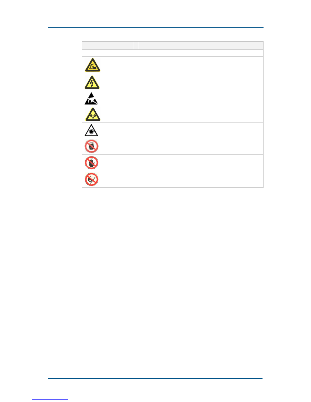
TABLE 3 – SAFETY SIGNS
Safety Signs Meaning
Danger: Indicates an imminently hazardous situation, which if
not avoided, will result in death or serious injury. This signal
word should be limited to only extreme situations.
Warning: Indicates a potentially hazardous situation, which if
not avoided, could result in death or serious injury.
Caution: Indicates a potentially hazardous situation, which if not
avoided, could result in minor or moderate injury. It may also
be used to alert against unsafe practices.
Note: Indicates a potentially hazardous situation, which if not
avoided, could result in injuries, equipment damage or
ZXG10-OB06 (V1.0) Integrated Outdoor GSM Base Station Technical Manual
xii Confidential and Proprietary Information of ZTE CORPORATION
Safety Signs Meaning
interruption of services.
Erosion: Beware of erosion.
Electric shock: There is a risk of electric shock.
Electrostatic: The device may be sensitive to static electricity.
Microwave: Beware of strong electromagnetic field.
Laser: Beware of strong laser beam.
No flammables: No flammables can be stored.
No touching: Do not touch.
No smoking: Smoking is forbidden.
How to Get in Touch
The following sections provide information on how to obtain support for
the documentation and the software.
Customer Support
If you have problems, questions, comments, or suggestions regarding
your product, contact us by e-mail at support@zte.com.cn. You can also
call our customer support center at (86) 755 26771900 and (86) 8009830-9830.
Documentation Support
ZTE welcomes your comments and suggestions on the quality and
usefulness of this document. For further questions, comments, or
suggestions on the documentation, you can contact us by e-mail at
doc@zte.com.cn; or you can fax your comments and suggestions to (86)
755 26772236. You can also explore our website at
http://support.zte.com.cn, which contains various interesting subjects like
documentation, knowledge base, forum and service request.

Confidential and Proprietary Information of ZTE CORPORATION 1
Chapter 1
System Architecture
This chapter describes the background, the standards followed, major
functions, system features, working principles and the general structure of
both software and hardware of ZXG10-OB06 (V1.0).
System Introduction
System Background
ZXG10-OB06 is one of the ZXG10-BTS series of base transceiver stations,
and is an integrated outdoor BTS for GSM. A single cabinet supports six
carriers at the maximum.
In one system, it integrates the following:
• Transmission functions
• Power supply
• Environment monitoring and temperature control
It is useful to install in either of the following two conditions:
• The cost of a standard equipment room is too high.
• There is no equipment room at the site, for example, in the
countryside or in the remote areas.
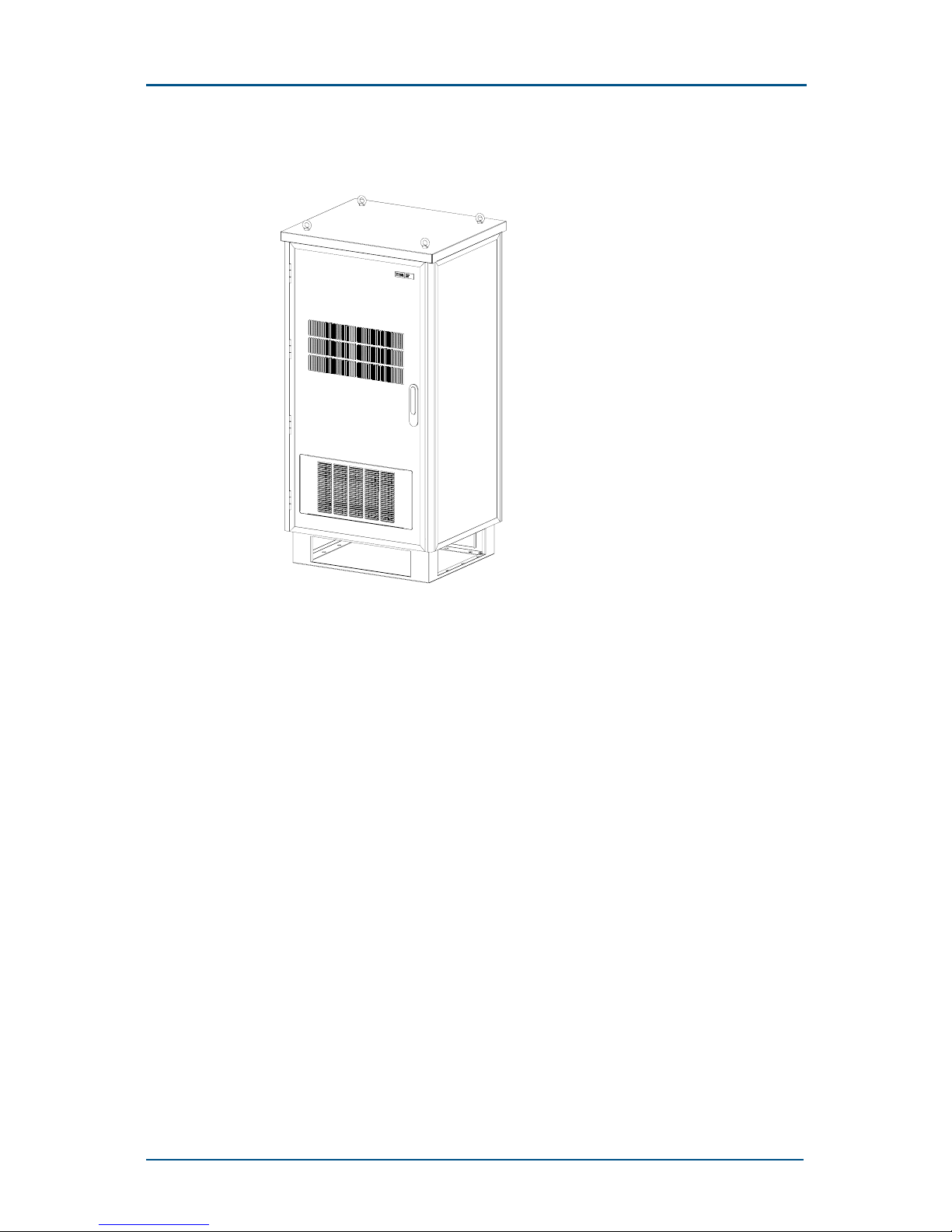
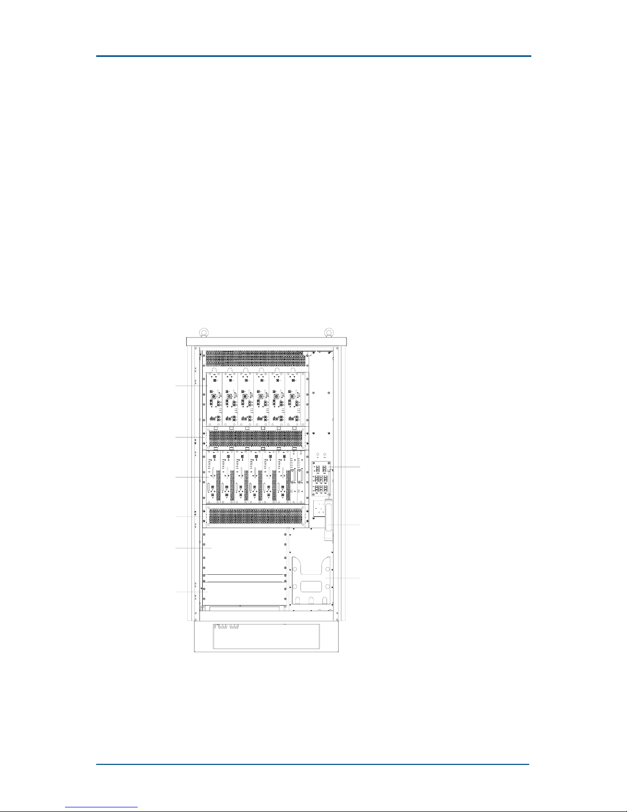
Figure 1 shows the whole ZXG10-OB06 appearance.
ZXG10-OB06 (V1.0) Integrated Outdoor GSM Base Station Technical Manual
2 Confidential and Proprietary Information of ZTE CORPORATION
FIGURE 1 – ZXG10-OB06 APPEARANCE
ZXG10-OB06 is located between BSC and MS in the GSM/GPRS network. It
connects to the BSC through Abis interface and to MS through Um
interface.
The ZXG10-OB06 provides the following functions:
• Serving as a radio transceiver for a cell
• Interaction between the BSC and a radio channel
• Wireless transmission with the MS and the related controlling function

Chapter 1 - System Architecture
Confidential and Proprietary Information of ZTE CORPORATION 3
Figure 2 shows the ZXG10-OB06 position (V.1.0) in a GSM/GPRS Network.
FIGURE 2 – ZXG10-OB06 P OSITION IN GSM/GPRS N ETWORK
SGSN
GGSN
PLMN
GGSN
SGSN
MSC
Internet
HLR
AUC
MSC/VLR
Gb
OMC
A
A
OB06
Gb
Um
BSC
ZTE
Abis
BTS
MS
BSC
OB06
ZTE
Abis
Um
MS
PDN
PSTN
ISDN
PSPDN
PLMN
Standards
ZXG10-OB06 complies with the following standards:
• Standards for RF interface:
• ETSI TS 101 087 (V5.0.0)
• GSM 05.05
• GSM 11.21
• ITUT-T G.703/G.704 standard Abis interface
• GSM 11.21 high/low temperature specifications
In terms of radio services, it complies with the following protocols and
specifications:
• GSM 03.60 General Packet Radio Service (GPRS)
• GSM 03.64 General Packet Radio Service (GPRS) Overall GPRS radio
interface description
• GSM 04.04 Technical Specification Group GSM/EDGE Radio Access
Network Layer 1 General requirements

ZXG10-OB06 (V1.0) Integrated Outdoor GSM Base Station Technical Manual
4 Confidential and Proprietary Information of ZTE CORPORATION
• GSM 04.06 Mobile Station – Base Station System (MS – BSS) interface
Data Link Layer (DLL) specification
• GSM 04.08 Mobile radio interface layer 3 specification
• GSM 04.60 General Packet Radio Service (GPRS) Mobile Station – Base
Station System (MS - BSS) interface Radio Link Control / Medium
Access Control (RLC/MAC) protocol.
• GSM 05.02 Multiplexing and multiple access on the radio path
• GSM 05.08 Radio subsystem link control
• GSM 08.58 Base Station Controller – Base Transceiver Station (BSC –
BTS interface Layer 3 specification
• ETSI 301 489-8 EMC specification
• R&TTE Directive 1995/5/EC
System Features
The ZXG10-OB06 (V1.0) is a compact outdoor BTS with a high capacity. A
single cabinet can support up to six carriers.
The main features of ZXG10-OB06 are as follows:
• Compatible with the following GSM Phases:
• GSM Phase I
• GSM Phase II
• GSM Phase II+
• GSM Frequencies:
• Support GSM900, EGSM900, GSM850, GSM1800, GSM1900
systems.
• Support different frequency band modules inserted in the same
cabinet.
• Provide the following TCH services:
• TCH/FS: Full-rate voice traffic channel
• TCH/HS: Half-rate voice traffic channel
• TCH/EFS: Enhanced full-rate voice traffic channel
• TCH/F9.6: 9.6 Kbps full-rate data traffic channel
• TCH/F4.8: 4.8 Kbps full-rate data traffic channel
• TCH/F2.4: 2.4 Kbps full-rate data traffic channel
• Able to operate in adverse outdoor environment:
• Cabinet features a framework of double-layer section aluminum
and a base of bended aluminum alloy plate. They are good in
erosion resistance and electric condition.
• Possess IP55 protection Level.

Chapter 1 - System Architecture
Confidential and Proprietary Information of ZTE CORPORATION 5
• Provide high-performance electromagnetic shielding and good heat
dissipation. Both front and back doors opens to facilitate maintenance.
• Features direct heat dissipation by wind. It uses fans of high wind
pressure and large wind capacity. Thus, it ensures quick and effective
heat dissipation for the modules.
• Features modular software/hardware design to enhance integration,
facilitate installation and maintenance and improve the system
reliability.
• Provide diversity receiving function. Main diversity technologies are as
follows:
• Space diversity
• Frequency diversity
• Time diversity
• Polarization diversity
• Receiving end adopts the Viterbi soft-decision algorithm. It improves
the channel decoding performance and increases the system receiving
sensitivity and anti-interference capability.
• Support frequency hopping. It improves the system capability against
Rayleigh fading.
• Support discontinuous transmission (DTX) mode. Transmit only the
comfort noise in the voice non-activated period. This reduces the
transmitter power and general interference level in the air signaling.
• Calculate time advance.
• Support configurations with 40 W or 80 W power consumption for
GSM900 and EGSM900 systems and 40 W for GSM1800, GSM1900 and
GSM850 systems.
• Support six TRXs per ZXG10-OB06 BTS for 40 W configuration for the
GMSK mode and 50 W for the 8PSK mode. It also supports S6/6/6
extension of 18 TRXs at the same site.
• Support three TRXs per ZXG10-OB06 BTS for 80 W configuration for
the GMSK mode and 50 W for the 8PSK mode. It also supports S3/3/3
extension of nine TRXs at the same site.
• Support star, chain and tree configuration of Abis interfaces.
• Support satellite transmission links of Abis interfaces, with the
unidirectional transmission delay of Abis interfaces being 260 ms.
• Support LAPD signaling one for four Terminal Equipment Identifier (TEI)
multiplex of Abis interfaces. That is, having pieces of LAPD-signaling
multiplexed into one 64 Kbps signaling time slot though TEI.
• Provide automatic crossover protection function for the Abis interface
link when any one of the cascaded ZXG10-OB06 BTSs is powered off.
• Support pre-processing of ZXG10-OB06 measurement reports.
• Support BS power control of statically six levels and dynamically 15
levels.
• Support all paging modes defined in GSM specifications.

ZXG10-OB06 (V1.0) Integrated Outdoor GSM Base Station Technical Manual
6 Confidential and Proprietary Information of ZTE CORPORATION
• Support synchronous, asynchronous, pseudo- synchronous and pre-
synchronous handovers.
• Provide functions as protection and electromagnetic filtration. The
power system features the following:
• AC input and DC output (over-voltage/under-voltage) protection
It keeps DC output until the temperature is more than -20°C and
cut it off when the temperature falls below -20°C.
• Lightening/surge prevention
• Burst interference resistance
• Cycle drop prevention
• Conduction interference resistance
• Anti-electromagnetic radiation functions
• Power system contains external high-capacity batteries. It provides a
function for management of secondary power down and batteries.
• Uses standard RS232 interface for connection with the local operation
and maintenance terminal. It also provides rapid and reliable online
software upgrade.
• Possess prompt alarm system for the following:
• Unattended BS
• Power supply
• Built-in tower amplifier system
• Support EDGE service hence has a higher data transmission rate by
means of 8PSK modulation.
• Support A51/A52 encryption algorithm at Um interface.
• Support ultra-distance coverage with a radius of 35 km ~ 120 km.
System Working Principle
ZXG10-OB06 (V1.0) system is composed of following units:
• Operation and maintenance unit
• Baseband processor
• RF unit
• Antenna feeder processor
• Transmission unit
• Power unit
• Heat exchanger
Chapter 1 - System Architecture
Confidential and Proprietary Information of ZTE CORPORATION 7
The working principle of the system is as follows:
• Downlink:
i. The ZXG10-OB06 receives data from BSC, including voice and
signaling data.
ii. The transmission unit sends signaling data to the operation &
maintenance unit for processing.
iii. The voice data are then sent to baseband processor for processing
of rate conversion, encryption and interleaving.
iv. Data are then sent to RF unit for modulation to high-frequency
signals.
v. Finally, data are then transmitted through the antenna feeder
processor.
• Uplink:
i. The antenna feeder processor receives the RF signals from the MS.
It then sends these signals to the RF unit to convert into digital
signals.
ii. The signals are then transmitted to baseband processor for rate
signals conversion, decryption and de-interleaving.
iii. After conversion to the code pattern, suitable for long-distance
transmission, the signals are sent to the BSC through the Abis
interface.
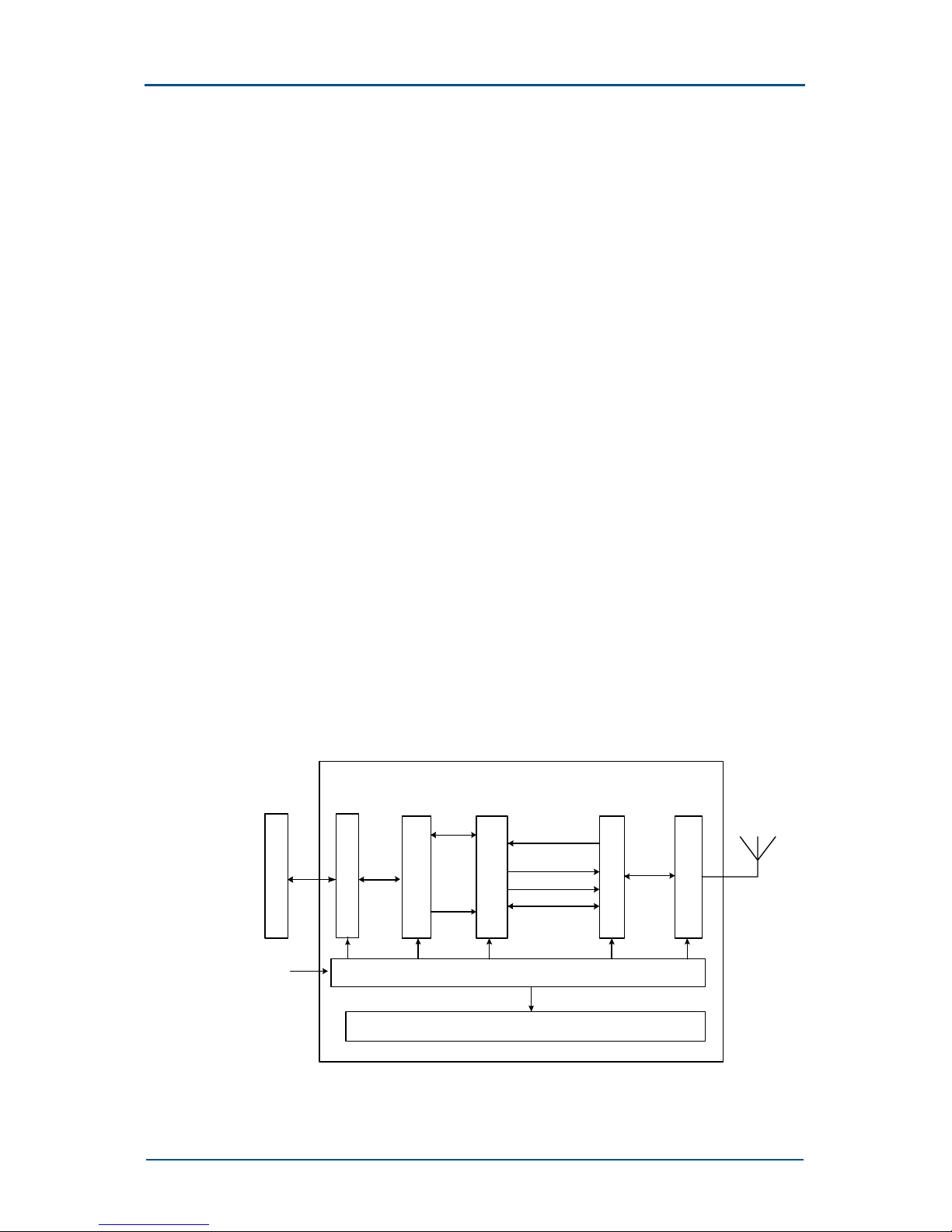
Figure 3 demonstrates the working principle of ZXG10-OB06 (V1.0).
FIGURE 3 – WORKING P RINCIPLE OF ZXG10-OB06 (V1.0)
ZXG10-OB06
Operation &
mainte nanc e unit
Baseband
proces sing unit
RF unit
Antenna
proces sing unit
Power unit
Heat exchanger
AC input
Data link
System
clock
RF demodulation
signal
Baseband
modulation signal
System clock
Control signal
RF signal
Um interface
Transmi ssion unit
BSC
Abis
ZXG10-OB06 (V1.0) Integrated Outdoor GSM Base Station Technical Manual
8 Confidential and Proprietary Information of ZTE CORPORATION
Hardware Structure
The ZXG10-OB06 (V1.0) hardware consists of the following units:
• Control and Maintenance Module (CMM)
• Transceiver Module (TRM)
• Antenna Equipment Module (AEM)
• Backplane Transmission Module (BTM)
• Heat Exchanger (HEX)
• Power Module (PWM)
Figure 4 shows the layout of the ZXG10-OB06 system.
FIGURE 4 – LAYOUT OF ZXG10-OB06 SYSTEM
1
2
3
4
5
6
7
8
9
1. AEM
2. AEM fan subrack
3. Transceiver Module
4. FDM fan subrack

Chapter 1 - System Architecture
Confidential and Proprietary Information of ZTE CORPORATION 9
5. Power Module
6. Transmission subrack
7. PDM breaker
8. Emergency light
9. Battery box
ZXG10-OB06 (V1.0) Integrated Outdoor GSM Base Station Technical Manual
10 Confidential and Proprietary Information of ZTE CORPORATION
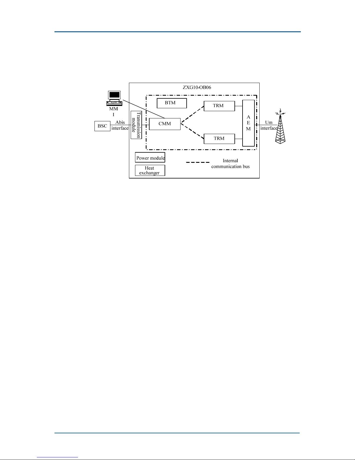
Figure 5 shows the hardware structure of the ZXG10-OB06.
FIGURE 5 – HAR DWARE STRUCTURE OF ZXG10-OB06 (V1.0)
Control & Maintenance Module (CMM)
CMM performs the following functions:
• Abis interface processing
• BTS operation & maintenance
• Clock synchronization and generation
• Internal/external alarm collection and processing
Transceiver Module (TRM)
TRM performs the following functions:
• Controls and processes the radio channels
• Transmit and receive the radio channel data
• Modulates and demodulates the baseband signals on the radio carrier
• Transmit and receives radio carriers in the GSM system.
TRM divides into three units by function:
• Transceiver Process Unit (TPU)
• Radio Carrier Unit (RCU)
• Power Amplifier Unit (PAU)

Chapter 1 - System Architecture
Confidential and Proprietary Information of ZTE CORPORATION 11
Transceiver Process Unit (TPU)
TPU implements the following functions:
• All functions of baseband data processing of all duplex channels on
TDMA frame.
• Conversion between LAPDm and LAPD protocols.
• Provide GPRS data service.
• Support CS1, CS2, CS3 and CS4 encoding modes.
Radio Carrier Unit (RCU)
RCU functions are as follows:
• Modulates baseband signals to carrier signals and up-converts
frequency.
• Down-coverts the frequency of received carrier signals.
• Controls the power statically and dynamically in the downlink direction
as required by GSM specifications.
Power Amplifier Unit (PAU)
• PAU amplifies the power of the radio carrier to provide the BS
equipment with sufficient transmission power.
• In GSM900 or EGSM900 bands, ZXG10-OB06 features a transceiver
unit with an output power of 80 W. This unit consists of two modules:
• Super Transceiver Module for GSM/EGSM 900 (STRG): It fulfills the
functions of the TPU and RCU.
• Super Power Amplifier for GSM/EGSM 900 (SPAG): Accomplishes
the functions of the PAU.
Antenna Equipment Module (AEM)
AEM accomplishes functions of duplex and distribution of air signals.
ZXG10-OB06 provides two units:
• Combiner Distribution Unit (CDU)
• Combiner Extension Unit (CEU)
AEM can provide the ZXG10-OB06 (V1.0) with different configurations
through combinations.
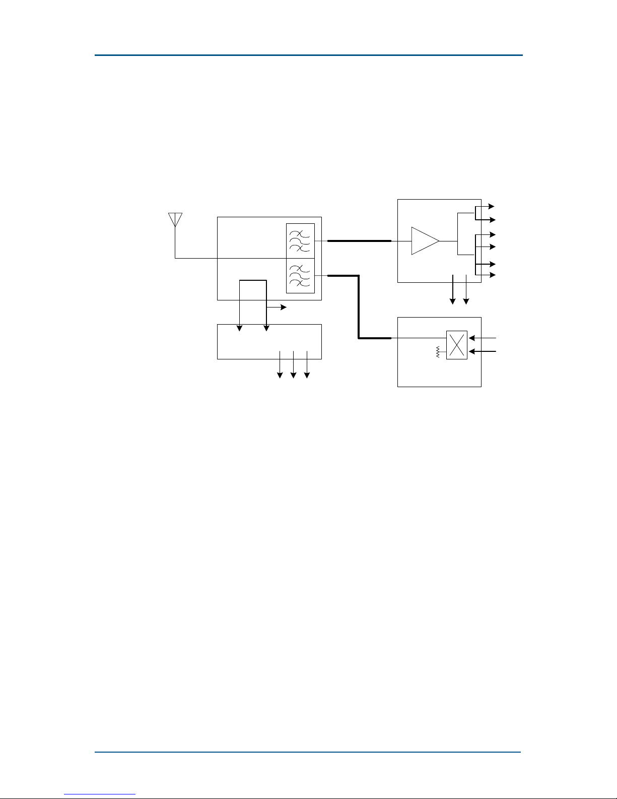
Combiner Distribution Unit (CDU)
CDU consists of four parts:
• Broadband combiner
• RX/TX duplexer
ZXG10-OB06 (V1.0) Integrated Outdoor GSM Base Station Technical Manual
12 Confidential and Proprietary Information of ZTE CORPORATION
• VSWR detection circuit
• Low Noise Amplifier (LNA) (including splitter)
Figure 6 shows the working principles of CDU.
FIGURE 6 – PRINCIPLES OF CDU
VSWR
ANT
Forward
Backward
Alarm
Rx/Tx duplexer
Rx_in
Tx_out
RX1
RX2
RX3
RX4
ERX1
ERX2
LNA_Splitter
Alarm
TX1
TX2
50ohm
Broadband combiner
RTE
CDU supports the following units:
• One 2-in-1 combiner
• One 1-to-4 low-noise amplifier with two extended receiving output
terminals
• One built-in duplexer
The combiner combines signals from multiple transmitters to one output
terminal.
The bidirectional coupler provides the test circuit with the SWR detection
and TX power monitoring functions. The control circuit implements the
SWR output.
The TX filter provides band-pass filtering for all TX output ports to avoid
interferences by TX frequencies on the RX frequencies.
The RX filter also acts as a band-pass filter. It provides suppression on the
interference beyond the RX band, especially the interference of the TX
band.
Chapter 1 - System Architecture
Confidential and Proprietary Information of ZTE CORPORATION 13
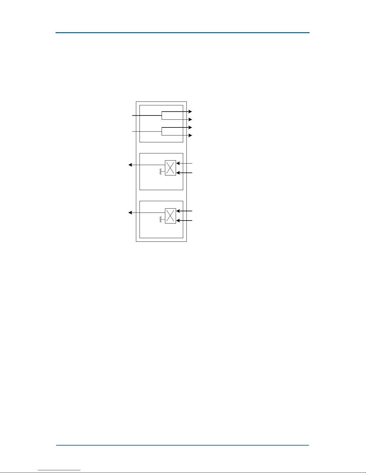
Combiner Extension Unit (CEU)
CEU consists of two 2-in-1 combiners and two 1-to-2 splitters. Figure 7
shows the structure of CEU.
FIGURE 7 – CEU STRUCTURE
To CDU TX1
RX1
RX2
RX3
RX4
ERX1
ERX2
Rx_Splitter
TX1
TX2
50ohm
Hybird_combiner
To CDU TX2
TX3
TX4
50ohm
Hybird_combiner
It can work together with CDU to constitute a 4-in-1 combiner/splitter.
Backplane Transmission Module (BTM)
BTM is responsible for transmitting messages between CMM, TRM and AEM.
At the same time, it provides interfaces for inputting and outputting
external signals.
Transmission Management Module (TMM)
TMM can be a product manufactured by a third party. In ZXG10-OB06,
there is a standard 19-inch 3U-high shelf for accommodation transmission
devices such as SDH and microwave.
Heat Exchanger (HEX)
HEX is composed of four key components as follows:
• Internal circulation fan
• External fan
• Heat exchanging chip
• Heater

ZXG10-OB06 (V1.0) Integrated Outdoor GSM Base Station Technical Manual
14 Confidential and Proprietary Information of ZTE CORPORATION
To ensure the normal operation, it must maintain the suitable temperature
of the system. HEX performs heat dissipation in high temperatures and
heating in low temperatures.
Power Module (PWM)
The PWM accomplishes lightning protection and rectification/filtration of AC
power. It also provides a function of overload/short circuit protection.
Power Distribution Module (PDM) is a sub-module of PWM and provides the
functions below:
• It outputs AC 220 V power to the heater of HEX and the maintenance
socket.
• Power plug-in box converts AC power to -48 V DC power for the CMM,
TRM/ETRM, TMM and fan of HEX.
Software Architecture
In software design, ZXG10-OB06 (V1.0) adopts modular and hierarchical
concepts to facilitate development and maintenance. The modules are
independent in function with each other and associates with each other
through the internal interfaces.
The core software can be downloaded from the background (OMCR),
facilitating service upgrade and version maintenance. It also provides
external interfaces to perform the following functions:
• To maintain the software
• To collect OB06 information
• To perform OB06 local tests
The internal software of ZXG10-OB06 (V1.0) is composed of four parts:
• Control & Maintenance Module (CMM)
• Frame Unit Controller (FUC)
• Channel Processing Module (CHP)
• Carrier Interface Processor (CIP)
Chapter 1 - System Architecture
Confidential and Proprietary Information of ZTE CORPORATION 15
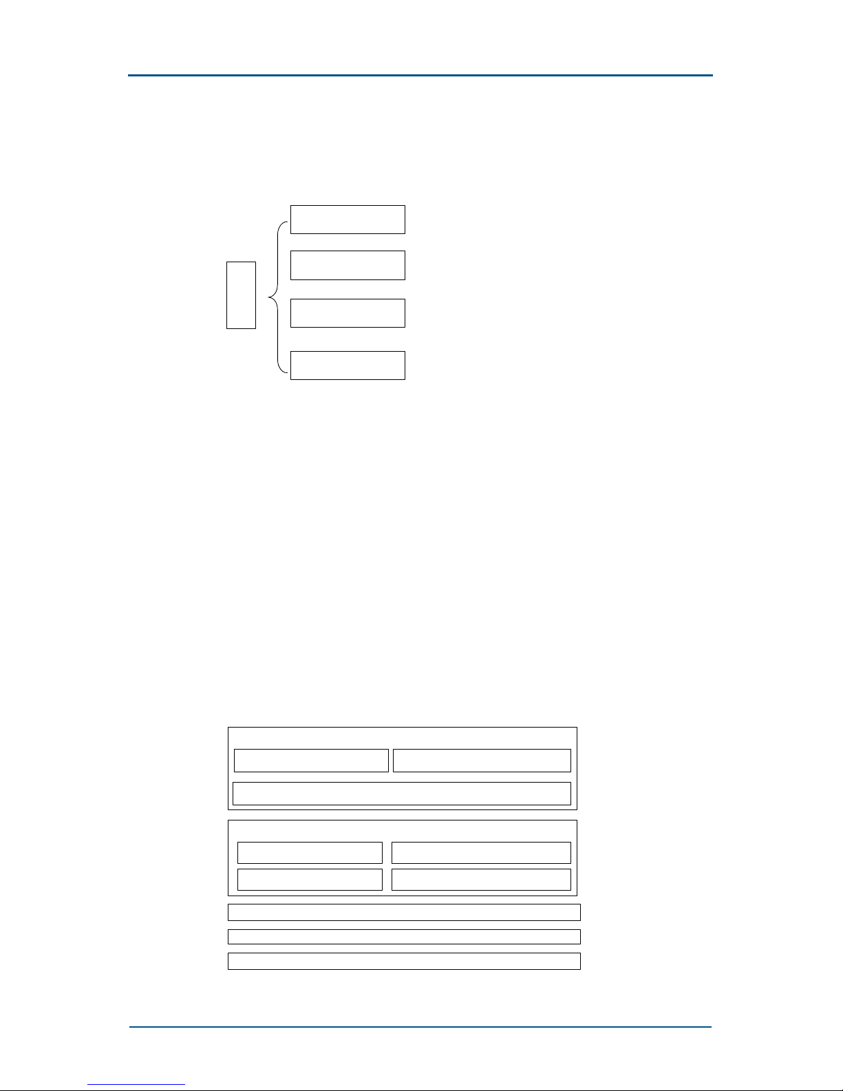
Software supports different platforms according to their function as shown
in Figure 8.
FIGURE 8 – SOFTWARE MODULES OF ZXG10-OB06 (V1.0)
System
software
CMM software module
FUC software module
CHP software module
CIP software module
Control & Maintenance Module (CMM)
The CMM of ZXG10-OB06 (V1.0) provides the following functions:
• Status management
• Configuration management
• Device management
• Monitoring management
• Test management
• Database management
• Supporting local O&M functions, including local parameter configuration
and alarm query
Figure 9 shows the layers of CMM software.
FIGURE 9 – CMM SOFTWARE MODULE STRUCTURE.
APP
pSOS+
Hardware
BSP
LMU
O&M
DBS
RUNCTRL
LNKDRV
LNKCTRL
RUNSPT
OSS

ZXG10-OB06 (V1.0) Integrated Outdoor GSM Base Station Technical Manual
16 Confidential and Proprietary Information of ZTE CORPORATION
The five layers, from bottom-to-top are as follows:
Hardware
The physical platform on which the CMM software runs.
Board-level Support Package (BSP)
BSP initializes CMM boards and provides drivers for the relevant parts of
the equipment. It provides consistent operation interfaces for the specific
details of the upper-level encapsulated hardware equipment and simplifies
the Operation Support System.
pSOS+ Operating System
It is a real-time multi-task operating system for commercial purposes and
with superior performance. The operating system has been successfully
applied to the next-generation BTS.
Operation Support System (OSS)
This layer consists of the following parts:
• RUNSPT: It is the core layer of OSS and a dispatch system, and
provides following functions:
• Process dispatch
• Process communication
• Memory management
• Timer management
• Process monitoring and abnormality capture
• RUNCTRL: It is the operation control layer of the system. It includes
the system control module and implements the power-on sequence for
application processes. In addition, the layer includes some
miscellaneous functions of the operating system such as redirection of
the printing messages.
• LNKDRV: It is the device driver and provides equipment independent
drivers for LNKCTR while working with BSP. This part also includes a
frame number synchronization module, which implements the frame
number synchronization between the following:
• Active/standby CMMs
• Active CMMs of the base and the extension cabinet
• Master CMM and TRMs
• LNKCTRL: It is the communication link control layer module and
consists of the following:
• LAPD communication link control module: LAPD is the
communication link control module of the Abis interface.
• HDLC communication link control module: HDLC is the
communication link control module inside the cabinet. They all
communicate in a point-to-point way.

Chapter 1 - System Architecture
Confidential and Proprietary Information of ZTE CORPORATION 17
Link Description
CCComm It is the auxiliary communication link between the master CMM of
the master rack and that of the extension cabinet. Physically, it is
a 2 M PCM line, which facilitates the centralized data collection of
LMU.
CMComm It is the communication link between the active and standby
CMMs. It implements the data synchronization between the CMMs.
It is 1 MHz HW-cable in actuality.
CTComm It is Foreground/background link control module with RS232 as its
physical interface. It is a self-defined point-to-point link protocol
and character-oriented single-bit stop and wait protocol.
• LMComm: Foreground/background link control module with RS232
as its physical interface. It is self-defined point-to-point link control
protocol and character-oriented single-bit stop and wait protocol.
APP layer
It is the application layer. It consists of three parts:
• O&M: As the core of the application layer, it receives the O&M
messages of the Abis interface and implements the following:
• Parameter configuration
• Status and alarm management
• Software version management
• Device test
• External alarm collections
• Data Base Subsystem (DBS): The application layer is designed with the
database as a core. The database coordinates assign configuration
parameters. It also synchronizes data between the active and standby
CMMs and between the foreground and the background.
• Local Maintenance Unit (LMU): It is the local O&M unit, including
foreground and background operation interface. It works with the
database synchronization module to complete the local parameter
configuration, equipment status and alarm collection. It also includes
operating interface of equipment test to implement test functions of
the local BTS. The system tool is a series of developer-oriented tools
for system diagnosis and test for the rapid location of faults.
Frame Unit Controller (FUC)
FUC software module is located in the TPU of the TRM module. It
processes radio signaling over every radio carrier and signaling on BSC
interface and manages all channels. Its major functions are as follows:

ZXG10-OB06 (V1.0) Integrated Outdoor GSM Base Station Technical Manual
18 Confidential and Proprietary Information of ZTE CORPORATION
• Processes and converts GSM signaling protocols, including the
following:
• Layer-2 protocol LAPD with BSC
• Layer-2 protocol HDLC with CMM
• Layer-2 protocol LAPDm with Um interface
• Layer-3 radio resources management protocol of GSM
• Responsible for the following:
• TDMA multi-frame framing of Um interface
• Frame number (FN) receiving
• Frequency hopping calculation
• Management & control over CHP
• Manages ZXG10-OB06 and loads DSP program
• Supports packet switching services (GPRS or PS)
Channel Processing Module (CHP)
CHP software module is located in the TPU of the TRM.
It implements all baseband channel processing and some corresponding
control functions, including channel encoding/decoding and demodulation.
Carrier Interface Processor (CIP)
CIP software module is located in the TPU of the TRM.
The functions of CIP software are as follows:
• GMSK (GSM modulation mode).
• 8PSK (EGPRS modulation mode).
• Software modulation.
• Power control.
• Collection and handling of AEM, amplifier, RCU and fan alarm
information.
 Loading...