

Zte ZXG10-BS30 Installation Manual

ZXG10-BS30
Compact Outdoor BTS
Installation Manual
Version 1.5
ZTE CORPORATION
ZTE Plaza, Keji Road South,
Hi-Tech Industrial Park,
Nanshan District, Shenzhen,
P. R. China
518057
Tel: (86) 755 26771900 800-9830-9830
Fax: (86) 755 26772236
URL: http://support.zte.com.cn
E-mail: doc@zte.com.cn

LEGAL INFORMATION
Copyright © 2006 ZTE CORPORATION.
The contents of this document are protected by copyright laws and international treaties. Any reproduction or
distribution of this document or any portion of this document, in any form by any means, without the prior written
consent of ZTE CORPORATION is prohibited. Additionally, the contents of this document are protected by
contractual confidentiality obligations.
All company, brand and product names are trade or service marks, or registered trade or service marks, of ZTE
CORPORATION or of their respective owners.
This document is provided “as is”, and all express, imp lied, or statutory warranties, representations or condition s
are disclaimed, including without limitation any implied warranty of merchantability, fitness for a particular purpose,
title or non-infringement. ZTE CORPORATION and its licensors sha ll not be liable for damages resulting from the
use of or reliance on the information contained herein.
ZTE CORPORATION or its licensors may have current or pending intellectual property rights or applications
covering the subject matter of this document. Except as expressly provided in any writte n license between ZTE
CORPORATION and its licensee, the user of this docum ent shall not acquire any license to the subject matter
herein.
The contents of this document and all poli cies of ZTE CORPORATION, including without lim itation policies related to
support or training are subject to change without n otice.
Revision History
Date Revision No. Serial No. Purpose
10-Aug-06 R1.0
sjzl20061196
English – For Customers
ZTE CORPORATION
Values Your Comments & Suggestions!
Your opinion is of great value and will help us improve the quality of our product
documentation and offer better services to our customers.
Please fax to: (86) 755-26772236; or mail to Documentation R&D Department,
ZTE CORPORATION, ZTE Plaza, A Wing, Keji Road South, Hi-Tech Industrial Park,
Shenzhen, P. R. China 518057.
Thank you for your cooperation!
Document
Name
ZXG10-BS30 (v1.5) Compact Outdoor BTS Hardware Installation Manual
Product Version V 1.5
Document Revision
Number
R1.0
Equipment Installation Date
Presentation:
(Introductions, Procedures, Illustrations, Completeness, Level of Detail, Organization,
Appearance)
Good Fair Average Poor Bad N/A
Accessibility:
(Contents, Index, Headings, Numbering, Glossary)
Good Fair Average Poor Bad N/A
Your evaluation
of this
documentation
Intelligibility:
(Language, Vocabulary, Readability & Clarity, Technical Accuracy, Content)
Good Fair Average Poor Bad N/A
Your
suggestions for
improvement of
this
documentation
Please check the suggestions which you feel can improve this documentation:
Improve the overview/introduction Make it more concise/brief
Improve the Contents Add more step-by-step procedures/tutorials
Improve the organization Add more troubleshooting information
Include more figures Make it less technical
Add more examples Add more/better quick reference aids
Add more detail Improve the index
Other suggestions
# Please feel free to write any comments on an attached sheet.
If you wish to be contacted regarding your comments, please complete the following:
Name Company
Postcode Address
Telephone E-mail

This page is intentionally blank.

Contents
About this Manual............................................................. i
Purpose................................................................................ i
Intended Audience .................................................................i
Prerequisite Skill and Knowledge.............................................. i
What is in this Manual ............................................................i
Related Documentation.......................................................... ii
Conventions ........................................................................ iii
How to Get in Touch............................................................. iv
Chapter 1..........................................................................1
Safety Instructions ..........................................................1
Overview ....................................................................... 1
Safety Symbols...............................................................1
Toxicant .............................................................................. 3
Electrical Safety.................................................................... 3
Antistatic ............................................................................. 4
Battery................................................................................ 5
Electromagnetic Radiation ...................................................... 6
Working at Heights ...............................................................6
Fans ...................................................................................7
High Temperature................................................................. 7
Plugging/Unplugging a Module ................................................ 8
Do Not’s .............................................................................. 8
Chapter 2..........................................................................9
Overview .......................................................................... 9
Equipment Installation and Commissioning Flow .................. 9
Equipment Parameters ........................................................ 11
Hardware Installation Flow ................................................... 13
Chapter 3........................................................................17

Installation Preparations...............................................17
Inspection on Installation Environment............................. 17
Inspection on Indoor Installation Environment.........................17
Inspection on Outdoor Environment .......................................18
Power Supply Requirements ........................................... 18
Safety Instructions ..............................................................18
Grounding and Lightning Protection Requirements....................19
Tools and Meter Requirements .............................................. 19
Unpacking and Inspection .............................................. 20
Unpacking Preparations........................................................ 20
Unpacking Instructions......................................................... 20
Chapter 4........................................................................23
Cabinet Installation .......................................................23
Cabinet Types .............................................................. 23
TSME.................................................................................24
DPM ..................................................................................25
STM .................................................................................. 26
HDSL................................................................................. 26
PWM or PWMD .................................................................... 27
HTM ..................................................................................29
Cabinet Installation Methods........................................... 30
Cabinet Installation on a Pole................................................30
Cabinet Installation on a Wall................................................ 35
Plugging / Unplugging a Module.............................................39
Chapter 5........................................................................43
Power and Grounding Cables Installation ....................43
Power Interface ............................................................ 43
AC Input Power Interface .....................................................43
DC Input Power Interface .....................................................44
DC Output Power Interface ...................................................45
Equipment Grounding .......................................................... 45
Chapter 6........................................................................49
Internal Cables Installation...........................................49
Backplane Interfaces ..................................................... 49
Site ID............................................................................... 51

Internal RF Cables for Single Cabinet ..................................... 57
Internal RF Cables for Dual Cabinets...................................... 58
Internal Signal Cables.......................................................... 59
Chapter 7........................................................................73
External Cables Installation ..........................................73
Chapter 8........................................................................83
Antenna Feeder System Installation.............................83
Antenna Feeder System Composition ............................... 83
Installation Accessories........................................................ 91
Antenna Feeder System Installation Flow.......................... 95
Engineering preparation....................................................... 96
Antenna Installation .......................................................... 100
Testing the Antenna Feeder System..................................... 116
Chapter 9......................................................................119
Hardware Installation Check.......................................119
Cabinet Checking .............................................................. 119
Cables Checking ............................................................... 119
Sockets, Plugs and Locking pieces checking .......................... 120
Labels Checking................................................................ 120
On-site Environment ......................................................... 120
Antenna Feeder System ..................................................... 121
Chapter 10....................................................................123
Power–ON/OFF Test....................................................123
Power-ON Check............................................................... 123
Power-ON Procedure ......................................................... 123
Power-OFF Procedure ........................................................ 124
Appendix A...................................................................125
Packing, Storage and Transportation..........................125
Packing ........................................................................... 125
Storage ........................................................................... 126
Transportation.................................................................. 127
Appendix B...................................................................129
CE Statement ...............................................................129

Appendix C ...................................................................131
Abbreviation.................................................................131
Figures..........................................................................133
Tables...........................................................................137
Index............................................................................139

This page is intentionally blank.


Confidential and Proprietary Information of ZTE CORPORATION i
About this Manual
Purpose
This manual describes the overall structure, basic parameters,
configurations and installation methods of ZXG10-BS30 (V1.5).
Intended Audience
This document is intended for engineers and technicians who
perform hardware installation for ZXG10-BS30 (V1.5).
Prerequisite Skill and Knowledge
To use this document effectively, users should have a general
understanding of wireless telecommunications technology.
Familiarity with the following is helpful:
ZXG10-BS30 (V1.5) system and its various components
What is in this Manual
This Manual contains the following chapters:
T ABLE 1 – CHAPTER S UMMARY
Chapter Summary
Chapter 1, Safety
Instructions
Describes the safety signs and their
meanings
Chapter 2, Overview Describes the installation and
commissioning flow of the BS30 (V1.5)
Chapter 3, Installation
Preparations
Describes the installation environment
check, tools requirements, documents
preparation, unpacking and inspection.
Chapter 4, Cabinet
Installation
Describes the internal module structure
and cabinet installation.
Chapter 5, Power and Describes the power and grounding cables

ZXG10-BS30 (V1.5) Compact Outdoor BTS Hardware Installation Manual
ii Confidential and Proprietary Information of ZTE CORPORATION
Chapter Summary
Grounding Cables
Installation
installation
Chapter 6, Internal
Cable Installation
Describes the back plane interfaces , RF
cable and signal cable installation
Chapter 7, External
Cable Installation
Describes the external cables including,
tail fiber, E1cable, power cables and main
contact point alert cable
Chapter 8, Antenna
Feeder System
Installation
Describes the antenna feeder system
composition and installation
Chapter 9, Hardware
Installation Check
Describes the system debugging check
after hardware installation
Chapter 10, Power –
ON/OFF
Describes the module plugging
/unplugging and power – ON/OFF methods
Appendix A Describes the packing methods, storage
conditions and transportation of the
equipment
Appendix C
CE Statement
Appendix B List of telecom industry abbreviations
Related Documentation
The following documentation is related to this manual:
ZXG10-BS30 (V1.5) Compact Outdoor BTS Technical Manual
ZXG10-BS30 (V1.5) Compact Outdoor BTS Hardware Manual
ZXG10-BS30 (V1.5) Compact Outdoor BTS Maintenance
Manual (Routine Maintenance)
ZXG10-BS30 (V1.5) Compact Outdoor BTS Maintenance
Manual (Emergency Handling)
ZXG10-BS30 (V1.5) Compact Outdoor BTS Maintenance
Manual (Trouble shooting)
ZXG10-BS30 (V1.5) Compact Outdoor BTS Guide to
Documentation
About this Manual
Confidential and Proprietary Information of ZTE CORPORATION iii
Conventions
ZTE documents employ the following typographical conventions.
T ABLE 2 - TYPOGRAPHICAL CONVENTIONS
Typeface Meaning
Italics References to other Manuals and documents.
“Quotes” Links on screens.
Bold Menus, menu options, function names, input
fields, radio button names, check boxes, dropdown lists, dialog box names, window names.
CAPS Keys on the keyboard and buttons on screens
and company name.
Constant width
Text that you type, program code, files and
directory names, and function names.
[ ] Optional parameters.
{ } Mandatory parameters.
| Select one of the parameters that are delimited
by it.
Note: Provides additional information about a
certain topic.
Checkpoint: Indicates that a particular step needs
to be checked before proceeding further.
Tip: Indicates a suggestion or hint to make things
easier or more productive for the reader.
T ABLE 3 - MOUSE O PERATION CONVENTIONS
Typeface Meaning
Click Refers to clicking the primary mouse button (usually
the left mouse button) once.
Double-click Refers to quickly clicking the primary mouse button
(usually the left mouse button) twice.
Right-click Refers to clicking the secondary mouse button
(usually the right mouse button) once.
Drag Refers to pressing and holding a mouse button and
moving the mouse.
Typographical
Conventions
Mouse
Operation
Conventions

ZXG10-BS30 (V1.5) Compact Outdoor BTS Hardware Installation Manual
iv Confidential and Proprietary Information of ZTE CORPORATION
How to Get in Touch
The following sections provide information on how to obtain
support for the documentation and the software.
If you have problems, questions, comments, or suggestions
regarding your product, contact us by e-mail at
support@zte.com.cn. You can also call our customer support
center at (86) 755 26771900 and (86) 800-9830-9830.
ZTE welcomes your comments and suggestions on the quality
and usefulness of this document. For further questions,
comments, or suggestions on the documentation, you can
contact us by e-mail at doc@zte.com.cn; or you can fax your
comments and suggestions to (86) 755 26772236. You can also
browse our website at http://support.zte.com.cn, which contains
various interesting subjects like documentation, knowledge base,
forum and service request.
Customer
Support
Documentation
Support

Confidential and Proprietary Information of ZTE CORPORATION 1
Chapter 1
Safety Instructions
This chapter explains the safety symbols and safety measures to
observe during routine maintenance.
Overview
It is important to read safety instructions before operation and
maintenance of ZXG10-BS30 equipment. These instructions are
supplementary to any local safety regulations in place. In case of
any conflict, local safety regulations shall prevail.
Maintenance personnel should have preliminary knowledge
about safety operations and must have received training on ZTE
equipment maintenance and operations.
Observe related equipment precautions and special safety
instructions during maintenance, provided by ZTE.
Some important safety instructions are discussed in the chapter.
ZTE shall not bear any liabilities incurred by violation of
universal safety operation requirements, or violation of safety
standards for designing, manufacturing and equipment usage.
Safety Symbols
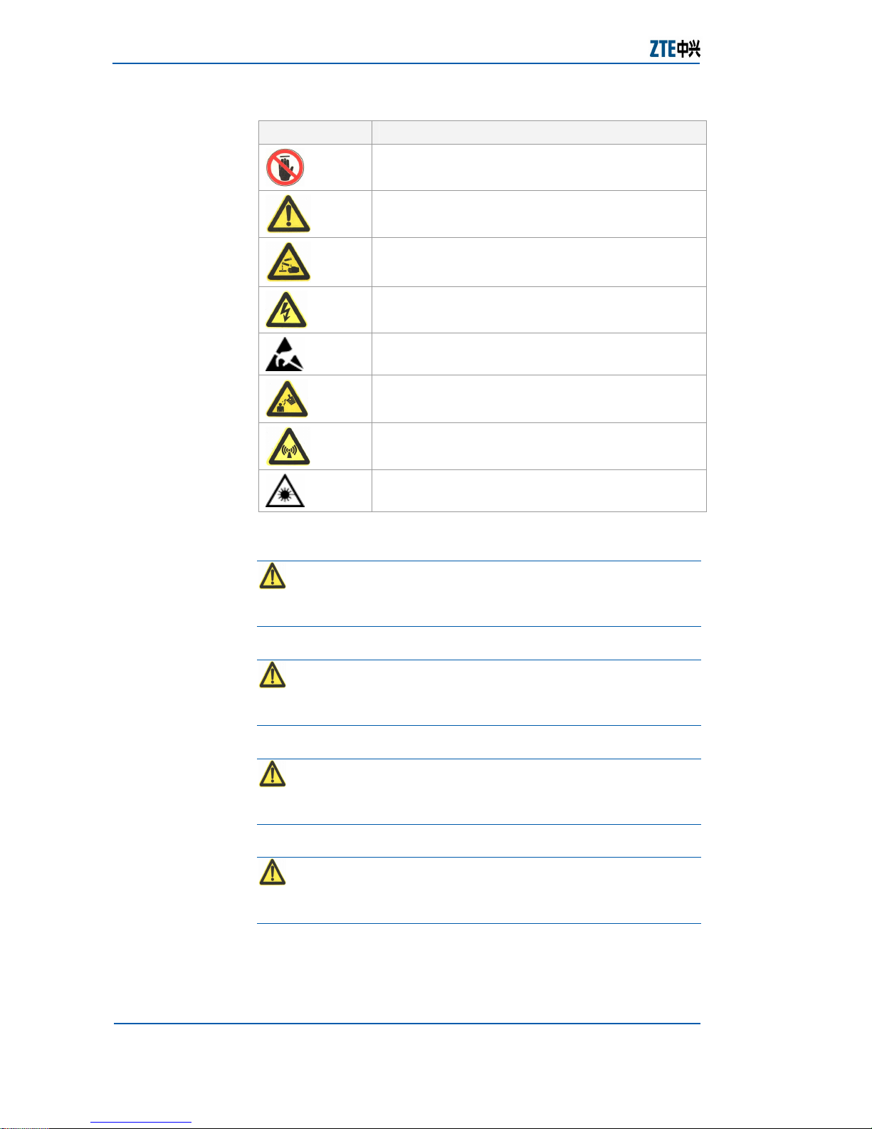
Table 4 lists general safety symbols used in the manual.
T ABLE 4 – GENERAL S AFETY SYMBOLS
Safety Symbol Meaning
No smoking: Smoking is forbidden.
No Flammables: No flammable materials can be
stored.
ZXG10-BS30 (V1.5) Compact Outdoor BTS Hardware Installation Manual
2 Confidential and Proprietary Information of ZTE CORPORATION
Safety Symbol Meaning
No touching: Do not touch.
Universal alarm: General safety precaution.
Erosion: Beware of erosion.
Electric shock: There is a risk of electric shock.
Electrostatic: Device may be sensitive to static
electricity.
High temperature: Surface is hot and may cause
personal injury if touched.
Microwave: Beware of strong electromagnetic field.
Laser: Beware of strong laser beam.
Universal alarm symbols comprises of four levels: Danger,
warning, caution and note in descending of criticality.
Danger: Indicates an imminently hazardous situation,
which, if not avoided, could result in death or serious injury.
Limit its use to only extreme situations.
Warning: Indicates a hazardous situation, which, if not
avoided, could result in serious injuries, equipment damages or
interruption of major services.
Caution: Indicates a potentially hazardous situation, which,
if not avoided, could result in moderate injuries, equipment
damages or partial service interruption.
Note: Indicates helpful information that if ignored, could
result in minor injuries, equipment damages or partial service
interruption.
Every safety symbol has a text description of its safety level and
a detailed description of its contents.
Chapter 1 - Safety Instructions
Confidential and Proprietary Information of ZTE CORPORATION 3
Toxicant
Warning: Beryllia is a toxic chemical commonly used in
transistors and base stations components, such as power
amplifier circuit and hybrid combiner circuit. Do not make direct
contact with these components.
Broken, ruptured or squashed beryllia components produce
beryllia powder, which is extremely harmful to human skin and
mucous membrane.
Beryllia components are dangerous only when they are broken,
so they need a lot of care while installing and disposing.
While disposing beryllia components, comply with local
regulations of chemical or special waste disposal.
In case of any accident or any physical contact involving beryllia,
rinse the wound with water and rush to a hospital for proper
treatment.
Personnel exposed to such components must have complete
knowledge about precautionary measures to avoid any hazards.
Warning: Some components in base station contain
chemicals like hydrochloride. These components release toxic
gas when burnt.
Do not burn components to prevent toxic gas release after
combustion. Dispose off according to the local regulations of
chemical or special waste disposal.
Electrical Safety
Warning: In high DC and AC voltage operation, use special
purpose tools.
Danger: Direct or indirect contact with high DC or AC
voltage through any moist object may result in serious injury.
AC equipment installation must comply with the local safety
regulations.
Personnel responsible for AC equipment installation must have
proper qualification in high DC and AC power.
Do not wear a watch, chain, bracelet, ring or any other
conductive objects while working with high voltages.
Prevent moisture from entering the equipment while working in
a moist environment.
Beryllia
Hydro Chloride
Tools
High Voltage
ZXG10-BS30 (V1.5) Compact Outdoor BTS Hardware Installation Manual
4 Confidential and Proprietary Information of ZTE CORPORATION
Note: Never install or uninstall power cables while they are
live because when touched with a conductor may produce sparks,
resulting in fire or damage to eyes.
Shut down the power supply before installing or uninstalling a
power cable.
Connect cables according to the labels and instructions given in
installation and hardware manuals.
Warning: Drilling in the cabinet without prior permission is
prohibited.
Unnecessary drilling can damage cables inside the cabinet. The
metal pieces blown due to drilling can cause short circuits in the
circuit board.
While drilling in the cabinet, wear gloves and move aside cables
in the cabinet. Protect eyes from metal pieces blowing while
drilling.
Clean the cabinet after drilling.
Danger: Do not perform high voltage and tower operations
in thunderstorm.
Thunderstorm produces a strong electromagnetic field in the
atmosphere, so avoid all tower and high voltage operations.
Take lightning protection measures by grounding the equipment
to prevent any damage.
Antistatic
Note: Static electricity produced by human body can
damage sensitive components on the circuit board, such as large
integrated circuits (ICs).
Friction caused by human body is the root cause of electrostatic
charge accumulation. In dry weather, the static charge carried
by human body can be up to 30 kV and can remain in human
body for a long time. Person carrying static charge can damage
a component by touching and hence transferring the charge to
the component.
To prevent human static charge from damaging sensitive
components, wear antistatic wrist strap and ground its other end
before touching the equipment or holding a plug board, circuit
board, IC chip etc.
To prevent accidental electric shock, serially connect the
connection cable between the wrist and grounding point with a
resistor above 1 MΩ. A resistor above 1 MΩ is enough to
discharge static voltage.
Power Cables
Drilling
Lightning
Chapter 1 - Safety Instructions
Confidential and Proprietary Information of ZTE CORPORATION 5
Check antistatic wrist strap regularly and never use a cable
other than the original cable that comes along with the wrist
strap.
Static-sensitive module or board should not touch the objects
that can carry static electricity. For example, friction caused by
package bags, transfer box and transfer belt made from
insulation plastic, may cause electrostatic shock to the
components because they can transfer static charge from human
body or floor.
Keep the static-sensitive module or board in anti-static bag
during storage and transportation.
Ground the test device to discharge the static charge before use.
Do not place the module or board near strong magnetic field,
such as cathode-ray tube of the monitor. Keep it at least 10 cm
away.
Battery
Danger: A short-circuited battery can be harmful to
human body. Although common batteries have low voltage, but
instant powerful current caused by short circuit can release a
great amount of energy.
Prevent metal objects to short circuit the battery, for example,
short circuit caused by mishandling the operation tools. If
possible, cut the battery supply before any operation.
Danger: Do not use any unsealed lead-acid battery,
because the gases released by the battery may erode the
equipment or cause fire. Fix the battery and place it horizontally.
Select a ventilated place for the battery having proper fire
protection measures because a battery can release combustible
gases. To prevent high temperature due to sunshine, equip the
battery room with sun-screening curtains.
Danger: Very high temperature of the battery may cause
deformation, damage or acid liquid overflow.
If the battery temperature exceeds 60 ºC, check acid liquid
overflow in the battery.
If acid liquid has overflowed, dispose off according to the local
regulations of chemical or special waste disposal.
Danger: If acid liquid overflows, absorb and neutralize it
as soon as possible.
Short Circuit
Harmful Gases
High
Temperature
Acid Liquids
ZXG10-BS30 (V1.5) Compact Outdoor BTS Hardware Installation Manual
6 Confidential and Proprietary Information of ZTE CORPORATION
Take special care of the acid liquids while moving a soaked
battery. If acid liquid overflows, use NaHCO3, Na2CO3 or
Na2CO3.10H2O to neutralize and absorb it.
Substances used for absorption and neutralization of acid liquids
must conform to battery manufacturers’ instructions.
Electromagnetic Radiation
An antenna of a device generates electromagnetic radiations.
The safety requirement might not be sufficient at a place too
near to the antenna. Personnel with proper training and relevant
qualifications must install and maintain the equipment.
Equipment radiation design shall comply with IEEE C95.1-1991.
Warning: Operating on high intensity RF equipment can
seriously affect human body.
During installation and maintenance of the antenna on a tower
mounted with several antennas from different operators, there
must be mutual agreement to shutdown the transmission.
Warning: During installation and servicing operations
around the operating antenna, keep adequate distance from the
antenna.
Do not unplug the transmitter output feeder connector or the
antenna feeder cable connector while the transmitter is
operating.
Shut down the transmitter before unplugging the feeder cable
connector or working beside the transmitter antenna.
Working at Heights
Warning: While working at heights, prevent objects from
falling down.
Working at heights should conform to local national service
regulation requirements, such as:
All personnel working at heights must undergo proper
training.
Prevent operation machinery and tools from falling down.
Wear helmet and safety belt as a safety precaution.
Wear cold-protection clothes in cold areas.
Check all hoisting equipment before working at heights.
Chapter 1 - Safety Instructions
Confidential and Proprietary Information of ZTE CORPORATION 7
Warning: Do not stay or walk under the hoisted weight.
To move, replace or dismantle heavy equipment, make sure that
appropriate facilities are available.
Personnel to perform hoisting tasks must have proper training.
Check hoisting tools and make sure they are firmly fixed on
support frame or walls.
Check the ladder if it is in good condition for use. Do not
overweight the ladder.
Before climbing on a ladder, make sure that someone is holding
it. Adopt proper safety measures when there is a tilt over 5 m, 3
m for an upright ladder or when used in dangerous operation
environment. Expand A-type ladder, completely.
Ideally, a ladder tilt is of 75 degrees. Bottom ends of the ladder
should not be slippery. Place the ladder firmly on a flat area. Do
not place it over the objects that can slide or move, such as
cartons and stones.
Always face the ladder while climbing it. Keep the center of
gravity within the ladder edges. Hold the ladder with one hand
and make sure to place both feet on the ladder. Do not climb
beyond last four steps. Ladder used to climb onto a roof should
be at least 1 m above the eave.
Fans
Warning: Keep fingers or body away from the running fan
blades. Do not use any tool on the fan before it is powered off
and fan blades stop.
When replacing parts, put screws, tools and parts in a safe place.
If they fall into the running fan, they can damage the fan or
other devices.
While working with devices near the fan, keep fingers or devices
away from the fan to avoid human injury or damage to devices.
High Temperature
Warning: Surface temperature of some components is
very high. Do not touch it.
Hoisting
Weights
Using Ladders

ZXG10-BS30 (V1.5) Compact Outdoor BTS Hardware Installation Manual
8 Confidential and Proprietary Information of ZTE CORPORATION
Plugging/Unplugging a Module
Note: Do not plug a board with force as it might bend the
pins at the backplane. Insert the board along the slot.
While holding a board in hand, keep hands off the board circuits,
components, connectors and wiring.
Do Not’s
Note: Do not conduct internal maintenance or equipment
debugging without prior permission.
Replacing parts or changing equipment may incur extra danger,
therefore, do not replace parts or change the equipment without
prior permission. To ensure safety and incase of any queries
contact local ZTE office or ZTE Customer Care Center.

Confidential and Proprietary Information of ZTE CORPORATION 9
Chapter 2
Overview
This chapter describes the installation and commissioning flow of
ZXG10-BS30 (V1.5) which makes the installation personnel to
have a complete understanding of the installation process.
Physical parameters of ZXG10-BS30 (V1.5) such as size, weight,
humidity and temperature also explained in this chapter.
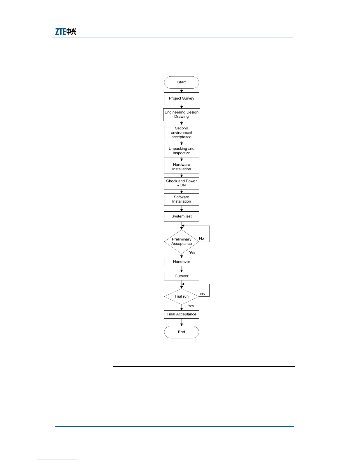
Equipment Installation and
Commissioning Flow
Equipment installation and commissioning flow indicates the
entire process from start (Project survey) to end (final
acceptance) as shown in Figure 1.
Project Survey
Environment survey should be conducted in the site address
according to the information collected from network planning
and provide related data for design and construction.
Engineering Design Drawing
Engineering design drawing should be done by the
professional institutes such as Posts and Telecommunication
Design Institutes according to the project survey results.
Second Environment Acceptance
Before starting the formal construction, implement the
second environmental acceptance according to ZXG10-BS30
(V1.5) Environment Acceptance Report and fill the report on
time. Engineering party should start the construction only
after the site environment as per the requirements.
Unpacking and Inspection
When equipment is delivered to the site, installation team
should determine the time for unpacking according to the
engineering preparation. Unpacking and inspection should be

ZXG10-BS30 (V1.5) Compact Outdoor BTS Hardware Installation Manual
10 Confidential and Proprietary Information of ZTE CORPORATION
carried out jointly by the installation team and ZTE. If any
party does the unilateral unpacking then that party is liable
for any damage to boards/parts or short shipment found
during unpacking.
Hardware Installation
Hardware installation should be done only under the
guidance of relevant professionals. It involves steps like
Positioning, Base installation, Cabinet installation and
Antenna feeder system installation.
Check and Power – ON
Conduct necessary inspection and power – ON the equipment
after completing the hardware installation.
Software Installation
Install the corresponding software and set the related
parameters.
System Test
Conduct a comprehensive test on the system to check the
system performance. If the test fails, continue further
adjustment until the requirement is met by the system.
Handover and Cutover
Handover the equipment to the user when normal operation
of the equipment is ensured.
Trial run
Equipment is in trial run phase for first several months after
the equipment is commissioned for operation. During this
period ZTE should be responsible for offering complete
technical support to the user.
Final Acceptance
If equipment stability and requirements are met by the
system; user and ZTE should conduct a joint acceptance test
to the equipment and sign the final acceptance certificate.
Note: Refer to the contract terms for details about project
survey, engineering design drawing, handover, cutover, trial run
and final acceptance.
Chapter 2 - Overview
Confidential and Proprietary Information of ZTE CORPORATION 11
F IGURE 1 – EQUIPMENT I NSTALLATION AN D C OMMISSIONING F LOW
Equipment Parameters
Dimensions
Dimension of the integrated equipment not including the
base (Height x Weight x Depth) is 500 mm x 400 mm x 284
mm.
ZXG10-BS30 (V1.5) Compact Outdoor BTS Hardware Installation Manual
12 Confidential and Proprietary Information of ZTE CORPORATION
Dimension of the cabinet base (Height x Weight x Depth) is
65mm x 360mm x 182.5mm.
Weight
Weight of the equipment with full configuration is
approximately 39kg.
Weight distribution of each cabinet part is as given below:
Parts Weight in kg
Cabinet main body 17
Transceiver for Station Module supports
EDGE (TSME)
8
Duplexer Module (DPM) 8
Heating Module (HTM) 1
SDH Transmission Module (STM) 2
Power Module (PWM) 2.5
Fan 0.5
Power Supply
ZXG10-BS30 (V1.5) supports power supply of 220 V AC and
-48 V DC.
220 V AC power supply
f Allowed voltage fluctuation range: 130 V to 300 V
f Allowed frequency fluctuation range: 45 Hz to 65 Hz
f Output voltage: -48 V DC (-60 V DC to -40 V DC
f Maximum output current: >6 A
f Adjustable current limited value: 8 A adjustable
f Maximum output power: 400 W
-48 V DC power supply
f Allowed voltage fluctuation range: -60 V DC to -40 V DC
Power Consumption
f Heating Module (HTM) power consumption: 300 W
f Total power consumption of the equipment(excluding
HTM): 260 W
f Transceiver Station Module supports EDGE (TSME): 160
W
f Duplexer Module (DPM): 15 W
f Power Module (PWM): 40 W
f Transmission Equipment (T150): 35 W
f Fan unit: 10 W
Others

Chapter 2 - Overview
Confidential and Proprietary Information of ZTE CORPORATION 13
f Ambient temperature outside the cabinet: -40
0
C to 55 0C
f Temperature inside the cabinet: ≤ 15
0
C
f Protection level: Protection level of the cabinet is IP55
f Maximum wind speed: 50 m/s
f Atmospheric pressure: 70 kPa to 106 KPa
f Mechanical Intensity: Mechanical intensity meets ETSI EN
301 489-1, ETSI EN 301 489-8 and Measurement
Methods of Electromagnetic Compatibility for 900/1800
MHz TDMA Digital Cellular Telecommunications System
Part 2: Base Station and Ancillary Equipment (YD/T
1139-2001).
f Safety: Safety meets Safety of Information Technology
Equipment (GB 4943-1995) standard.
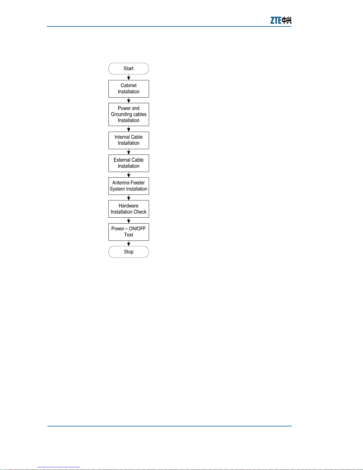
Hardware Installation Flow
ZXG10-BS30 (V1.5) can be installed in various methods which
include installation on walls or supportive poles depending upon
the geographic environment. Installation on the wall is simple
and low cost but it is applicable only if there is an existing wall.
Installation on a supportive pole is applicable only when a pole is
setup. Hardware installation flow is shown in Figure 2.
ZXG10-BS30 (V1.5) Compact Outdoor BTS Hardware Installation Manual
14 Confidential and Proprietary Information of ZTE CORPORATION
F IGURE 2 – HARDWARE I NSTALLATION F LOW
Cabinet Installation
Cabinet installation includes installing the cabinet on the
walls and supportive poles. For details refer Chapter 4
Cabinet Installation.
Power and Grounding cables Installation
Power and Grounding cables installation includes power and
ground cable interfaces. For details refer Chapter 5 Power
and Grounding Cables Installation
.
Internal Cable Installation
Internal cables for ZXG10-BS30 (V1.5) are connected before
delivery to avoid connecting them on the site. Cable
connections can be changed according to the connection
relationship. For details refer Chapter 6 Internal Cables
Installation
.
External Cable Installation
Chapter 2 - Overview
Confidential and Proprietary Information of ZTE CORPORATION 15
External cable installation includes O and M interface, cables
connected between the racks and E1 interface. For details
refer Chapter 7 External Cables Installation
.
Antenna Feeder System Installation
Antenna feeder system installation includes poles, iron tower,
jumpers, antenna and feeder installation and connection. For
details refer Chapter 8 Antenna Feeder System Installation
.
Hardware Installation Check
After hardware installation it is necessary to debug and
check before the final commissioning and operation. For
details refer Chapter 9 Hardware Installation Check
.
Power – ON/OFF Test
This includes plugging / unplugging a module and Power -
ON/OFF of the equipment. For details refer Chapter 10
Power–ON/OFF Test
.
Hardware installation is a critical step in the whole installation
process. So hardware installation should be done only under the
guidance of well trained and experienced professionals.
Note: Non-professionals should maintain or debug the
interior of any equipment only if instructed by the professionals
on the site.
Replacing any parts or altering the equipment might result in
unexpected danger. Make sure not to replace any parts or
alter the equipment without any authorization.
Electrostatic: Wear an antistatic wrist strap when
installing and maintaining the equipment.

ZXG10-BS30 (V1.5) Compact Outdoor BTS Hardware Installation Manual
16 Confidential and Proprietary Information of ZTE CORPORATION
This page is intentionally blank.
 Loading...