

Zte ZXG10 BS21 Maintenance Manual

ZXG10 BS21
Compact Out door BTS for GSM
Maintenance Manual
V ersion 2.2
ZTE CORPORATION
ZTE Plaza, Keji Road South,
Hi-Tech Industrial Park,
Nanshan District, Shenzhen,
P. R. China
518057
Tel: (86) 755 26771900 800-9830-9830
Fax: (86) 755 26772236
URL: http://support.zte.com.cn
E-mail: doc@zte.com.cn

LEGAL INFORMATION
Copyright © 2005 ZTE CORPORATION.
The contents of this document are protected by copyright laws and international treaties. Any reproduction or distribution of
this document or any portion of this document, in any form by any means, without the prior written consent of ZTE
CORPORATION is prohibited. Additionally, the contents of this document are protected by contractual confidentiality
obligations.
All company, brand and product names are trade or service marks, or regis tered trade or service marks, of ZTE
CORPORATION or of their respective owners.
This document is provided “as is”, and all express, implied, or statutory warranties, representations or conditions are
disclaimed, including without limitatio n any implied warranty of merchantability, fitness f or a p a rticular purpose, title or noninfringement. ZTE CORPORATION and its lice nsors shall not be liable for damages resulting from the use of or reliance on
the information contained herein.
ZTE CORPORATION or its licensors may have current or pending intellectual property rights or applications covering the
subject matter of this document. Except as expressly provided in any written license between ZTE CORPORATIO N and its
licensee, the user of this document shall n ot acquire any license to the subject matter herein.
The contents of this document and all policies of ZTE CORPORATION, including without limitation policies related to support
or training are subject to change without notice.
Revision History
Date Revision No. Serial No. Description
05/17//2005 R1.0 sjzl20051442
05/19/2007 R1.1 sjzl20051442 Updated
ZTE CORPORATION
Values Your Comments & Suggestions!
Your opinion is of great value and will help us improve the quality of our
product documentation and offer better services to our customers.
Please fax to: (86) 755-26772236; or mail to Publications R&D
Department, ZTE CORPORATION, ZTE Plaza, A Wing, Keji Road South,
Hi-Tech Industrial Park, Shenzhen, P. R. China 518057.
Thank you for your cooperation!
Document
Name
ZXG10 BS21 (V2.2) Compact Outdoor BTS for GSM Maintenance Manual
Product
Version
V2.2
Document
Revision Number
R1.1
Equipment Installation Date
Presentation:
(Introductions, Procedures, Illustrations, Completeness, Level of Detail, Organization,
Appearance)
Good Fair Average Poor Bad N/A
Accessibility:
(Contents, Index, Headings, Numbering, Glossary)
Good Fair Average Poor Bad N/A
Your evaluation
of this
documentation
Intelligibility:
(Language, Vocabulary, Readability & Clarity, Technical Accuracy, Content)
Good Fair Average Poor Bad N/A
Your
suggestions for
improvement
of this
documentation
Please check the suggestions which you feel can improve this documentation:
Improve the overview/introduction Make it more concise/brief
Improve the Contents Add more step-by-step procedures/tutorials
Improve the organization Add more troubleshooting information
Include more figures Make it less technical Add more examples
Add more/better quick reference aids Add more detail Improve the index
Other suggestions
___________________________________________________________________________
___________________________________________________________________________
___________________________________________________________________________
___________________________________________________________________________
___________________________________________________________________________
# Please feel free to write any comments on an attached sheet.
If you wish to be contacted regarding your comments, please complete the following:
Name Company
Postcode Address
Telephone E-mail

This page is intentionally blank.

Content s
About this Maintenance Manual ...............................................................xi
Purpose of this Maintenance Manual........................................................................ xi
Typographical Conventions.....................................................................................xii
Mouse Operation Conventions................................................................................xiii
How to Get in Touch .............................................................................................xiii
Customer Support .................................................................................................................xiii
Documentation Support ......................................................................................................... xiii
Chapter 1........................................................................................ 1
Maintenance Security.................................................................................1
Overview ...............................................................................................................2
Symbol Description................................................................................................. 2
Toxic Substances.................................................................................................... 4
Beryllia ...................................................................................................................................4
Hydrochloride..........................................................................................................................4
Electrical Safety...................................................................................................... 5
Tools ......................................................................................................................................5
High Voltage ...........................................................................................................................5
Power Cord .............................................................................................................................5
Drilling ....................................................................................................................................5
Thunder ..................................................................................................................................6
Antistatic ............................................................................................................... 6
Storage Battery ...................................................................................................... 7
Short Circuit ............................................................................................................................ 8
Hazardous Gases .................................................................................................................... 8
High Temperature ...................................................................................................................8
Acid Liquid ..............................................................................................................................8
Storage Battery Replacement ..................................................................................................9
Electromagnetic Radiation ....................................................................................... 9
Working at Heights ............................................................................................... 10
Hoisting Heavy Objects..........................................................................................................10
Using Ladders .......................................................................................................................10
Fans .................................................................................................................... 11

High Temperature ................................................................................................ 11
Board Plugging/Unplugging ................................................................................... 11
Do-Nots ............................................................................................................... 12
Chapter 2...................................................................................... 13
Maintenance Overview............................................................................ 13
Categories of Daily Maintenance............................................................................. 14
Common Maintenance Methods ............................................................................. 14
Precautions on Daily Maintenance .......................................................................... 16
Chapter 3...................................................................................... 19
Routine Maintenance .............................................................................. 19
Daily Routine Maintenance .................................................................................... 20
Viewing Current Alarms .........................................................................................................20
Viewing Alarms in Each Module .............................................................................................. 22
Viewing Current Notification Information ................................................................................ 25
Viewing Real-time Attributes of a Carrier ................................................................................ 29
Creating Daily Performance Report......................................................................................... 30
Creating a Daily Traffic Report................................................................................................ 35
Weekly Routine Maintenance ................................................................................. 39
Viewing History Alarms ..........................................................................................................39
Collecting Alarm Frequency Statistics ..................................................................................... 44
Analyzing Performance Report ............................................................................................... 48
Monthly Routine Maintenance ................................................................................ 48
Creating Monthly Performance Report ....................................................................................48
Collecting Statistics of Bad Cells ............................................................................................. 53
Analyzing and Processing Reports ..........................................................................................57
Generating Monthly Operation Report..................................................................................... 58
Biannual Routine Maintenance ............................................................................... 58
Checking BS21 AC Power ...................................................................................................... 59
Checking Running Status of Heat Exchanger........................................................................... 60
Checking Dust-Proof Status ................................................................................................... 60
Checking Running Status of CMM Module ...............................................................................61
Checking Running Status of ETRM Module .............................................................................. 64
Checking Running Status of ECDU Module .............................................................................. 67
Measuring Amplifier Output Power ......................................................................................... 69
Measuring SWR of Antenna Feeder ........................................................................................ 69
Calibrating Clock ................................................................................................................... 71
Checking Fastness of Antennae and Towers ............................................................................ 72
Checking Obliquity of Directional Antennae ............................................................................. 72
Checking whether Antenna Feeder Connectors and Lightning Protection Grounding Kit are
Waterproof............................................................................................................................74

Checking E1 Interfaces ..........................................................................................................75
Checking Antenna Feeder Interfaces ......................................................................................76
Checking Whether Lightning Protection Arrester is in Good Condition .......................................76
Checking whether Grounding Cable is Reliable ........................................................................78
Grounding Resistance Test..................................................................................................... 78
Checking Running Status of Transmission Equipment.............................................................. 79
Checking Running Status of UPS ............................................................................................79
Chapter 4...................................................................................... 81
Notification and Handling ....................................................................... 81
Summary of Notification Information ...................................................................... 82
No Traffic Notification in BS Cell ............................................................................. 82
Chapter 5...................................................................................... 85
Alarms and Handling............................................................................... 85
Summary of Alarms.............................................................................................. 86
CMM Alarms......................................................................................................... 90
CMM Power Failure ................................................................................................................ 90
LAPD Long-Time Link Disconnection .......................................................................................91
CMM's FLASH Programming Failure ........................................................................................ 92
HW Long Time Link Disconnection .......................................................................................... 92
Power Over/Under-Voltage Alarms ......................................................................................... 93
Clock Exceptions (13M, FCLK, SYNCLK).................................................................................. 93
Software Accumulative Frame Number Inconsistent with Hardware Accumulative Frame Number
............................................................................................................................................94
Alarms of Communication Link to Main Rack...........................................................................95
Alarm with Communication Link between Master Rack and Left/Right Slave Rack ..................... 95
E1 Carrier Wave Receiving Alarm (A, D and E interfaces) ........................................................96
Out-of-Frame Alarm at Receiving End of E1 interfaces (A, D and E interfaces).......................... 97
Forward Slip Code Indication at Transmitting End of E1 Interfaces (A, D and E interfaces) ........97
Backward Slip Code Indication at Transmitting End of E1 Interfaces (A, D and E Interfaces) ..... 98
Forward Slip Code Indication at Receiving End of E1 Interfaces (A, D and E Interfaces) ............99
Backward Slip Code Indication at Receiving End of E1 Interfaces (A, D and E Interfaces) ........100
ETRM Alarm ....................................................................................................... 101
Dry Contact Alarm ............................................................................................................... 101
LNA (Low Noise Amplifier) Alarm.......................................................................................... 102
Power Alarm for Tower Mounted Amplifier ............................................................................102
AEM SWR Minor Alarm ........................................................................................................ 103
AEM SWR Major Alarm ........................................................................................................ 103
AEM Power Alarm ................................................................................................................ 104
AEM Type Alarm.................................................................................................................. 104
AEM Not-in-Position Alarm ................................................................................................... 105
TPU’s CHP DSP0 Initialization Failure ....................................................................................105

TPU’s CHP DSP1~3 Initialization Failure ................................................................................ 106
RFAD6620 Initialization Failure ............................................................................................. 107
RFAD6620 Resource Unavailable .......................................................................................... 107
CIP Resource Unavailable .................................................................................................... 108
TPU’s FLASH MEMORY Error ................................................................................................. 109
WATCHDOG Overflow in TPU’s CHP DSP0............................................................................. 109
WATCHDOG Overflow in TPU’s CHP DSP1~3 ........................................................................110
WATCHDOG Overflow in FUC ............................................................................................... 111
Parameter Configuration Error in TPU’s Channel 0~7 ............................................................ 111
Inconsistent Cell Parameter Configuration............................................................................. 112
Inconsistent FUC Software Versions ..................................................................................... 112
Inconsistent CHP Software Versions .....................................................................................113
Temporary No Response from FUC’s L3 Software.................................................................. 113
Disconnected LAPD Link between FUC and BSC ....................................................................114
Interrupted Communication between CMM and FUC ............................................................. 115
TPU’s CIP Initialization Failure .............................................................................................. 116
CIP Parameter Configuration Error ....................................................................................... 116
WATCHDOG Overflow in TPU’s CIP ....................................................................................... 117
Inconsistent CIP Software Versions ...................................................................................... 117
Alarm with Clock between TPU and CMM .............................................................................. 118
TPU Power Alarm ................................................................................................................ 119
TPU Frame Number Alarm ................................................................................................... 119
Receiving RF Local Oscillator PLL1~2 out of Lock .................................................................. 120
Transmitting RF Local Oscillator PLL1~2 out of Lock .............................................................. 121
52 M Reference Clock PLL Out of Lock .................................................................................. 121
Transmitting IF Local Oscillator PLL Out of Lock..................................................................... 122
PA Voltage SWR Alarm ........................................................................................................ 123
PA Overheat Minor Alarm..................................................................................................... 123
PA Overheat Major Alarm .................................................................................................... 124
PA Output Power Alarm ....................................................................................................... 124
PAS Power Amplifier Power Supply Over-voltage Alarm......................................................... 125
PAS Power Amplifier Power Supply Under-voltage Alarm ....................................................... 125
DLRC_AL Downward Link Check Error .................................................................................. 126
Chapter 6.................................................................................... 127
Troubleshooting .................................................................................... 127
Summary of Common Problems .......................................................................... 128
List of Major Faults.............................................................................................. 129
Troubleshooting Procedure of Components Failures ............................................... 129
Troubleshooting at BS Commissioning Stage......................................................... 130
BS Works Normally but Mobile Phone Has no Signals or Cannot Access Network .................... 130
Handling of SWR Major Alarms............................................................................................. 132

Poor Conversation Quality at BS........................................................................................... 134
Troubleshooting in BS Maintenance Stage............................................................. 137
Shrinkage of BS Coverage ................................................................................................... 137
Cell Carrier not Occupied ..................................................................................................... 140
LAPD Broken-Link of BS Carrier............................................................................................ 142
BS in Normal Status but BS Handover Is Abnormal............................................................... 147
Handling Lightning-Stricken BS Faults .................................................................................. 149
MS Signal is not Stable in Idle State .....................................................................................151
Unstable MS Signal in Conversation...................................................................................... 153
TCH Assigned with Low Success Ratio and Calls Are Difficult to Get through ........................... 154
MS Echo during Conversation............................................................................................... 156
Troubleshooting in BS Cutover and Expansion Stages............................................ 158
Unidirectional Mobile Phone Calls .......................................................................................... 158
SDCCH Occupied too Long ................................................................................................... 160
Call Drop Rate in Cell Rises Suddenly ................................................................................... 163
Chapter 7.................................................................................... 167
Collection of Maintenance Experience.................................................. 167
Reference for Wireless Parameters Adjustment during Commissioning .................... 168
Adjusting List of Adjacent Cells and List of Carrier-Sense Frequencies .................................... 168
Adjusting Wireless Parameters ............................................................................................. 170
Others ................................................................................................................................171
Analysis of Bird928 Mobile Phone’s Failure to Access Network................................. 172
Configuration Method for Intra-Cell Handover ....................................................... 174
Appendix A .................................................................................175
Replacement of Modules and Parts ...................................................... 175
Overview ........................................................................................................... 175
CMM Replacement .............................................................................................. 176
ETRM Replacement............................................................................................. 177
AEM Replacement............................................................................................... 178
PSM Replacement............................................................................................... 179
Power Lightning Protection Module Replacement ................................................... 180
Backplane Replacement ...................................................................................... 181
Heat Exchanger Replacement .............................................................................. 182
Trunk Cable Replacement.................................................................................... 183
RF Cable Replacement ........................................................................................ 184
Antenna Feeder Lightning Arrester replacement .................................................... 185
Cabinet-Bottom 1/2 Soft Jumper Replacement...................................................... 187
Tower Top 1/2” Soft Jumper Replacement ............................................................ 188
Feeder Connectors Replacement .......................................................................... 190

Tower Amplifier Replacement .............................................................................. 191
Antenna Replacement ......................................................................................... 192
Appendix B .................................................................................195
Common Maintenance Tables............................................................... 195
Daily Maintenance Record Table........................................................................... 195
Weekly Maintenance Record Table ....................................................................... 196
Monthly Maintenance Record Table ...................................................................... 197
Biannual Maintenance Record Table ..................................................................... 198
Emergency Failure Record Table .......................................................................... 199
Appendix C .................................................................................201
Use of Common Instruments and Meters ............................................ 201
SAGEM (OT35) Test Mobile Phone........................................................................ 201
Basic Functions ................................................................................................................... 201
Operation Description .......................................................................................................... 202
Engineering Test Mode of ZTE289 Mobile Phone .................................................... 211
Key Description ................................................................................................................... 211
How to Enter Engineering Mode ........................................................................................... 211
How to Close Engineering Mode ........................................................................................... 211
Instructions of Engineering Mode Menu ................................................................................ 211
BIRD Power Meter .............................................................................................. 214
BIRD Power Meter Components ...........................................................................................214
Usage .................................................................................................................................215
HP8954E Spectrum Analyzer ............................................................................... 217
Components ....................................................................................................................... 218
Usage .................................................................................................................................218
Antenna Feeder Tester (SITE MASTER S332B) ...................................................... 222
Procedure for Testing SWR .................................................................................................. 222
Test Procedure of DTF ......................................................................................................... 223
Appendix D.................................................................................225
Operation Maintenance Quality Indexes of Certain Telecom Network
(Wireless Part)...................................................................................... 225
Abbreviations .............................................................................227
Figures........................................................................................233
Tables .........................................................................................235

Confidential and Proprietary Information of ZTE CORPORATION xi
About this Maintenance
Manual
ZXG10 BS21 (V2.2) Base Station Transceiver Station Maintenance Manual
describes maintenance safety, routine maintenance items and methods,
handling of alarm and notification information, handling of common faults
and maintenance experience of the ZXG10 BS21 (V2.2). The manual
serves as a reference manual in the maintenance and fault handling of the
ZXG10 BS21 (V2.2) equipment.
The complete set of manuals is listed below:
ZXG10 BS21 (V2.2) Compact Outdoor BTS for GSM Guide to
Documentation
ZXG10 BS21 (V2.2) Compact Outdoor BTS for GSM Technical Manual
ZXG10 BS21 (V2.2) Compact Outdoor BTS for GSM Hardware Manual
ZXG10 BS21 (V2.2) Compact Outdoor BTS for GSM Installation Manual
ZXG10 BS21 (V2.2) Compact Outdoor BTS for GSM Maintenance Manual
Purpose of this Maintenance
Manual
Chapter 1, Maintenance Security, presents the meanings of the signs used
in this manual. It also covers some safety precautions related to the
installation procedure, such as precautions against high voltage,
thunderstorms and overhead operations.
Chapter 2, Maintenance Overview, introduces daily maintenance
categories, common maintenance methods and some precautions on
maintenance of ZXG10 BS21 (V2.2) base station controllers.
Chapter 3, Routine Maintenance, explains routine maintenance items of
the ZXG10 BS21 (V2.2) base station controller equipment and details
instrument requirements, check methods and fault handling of individual
maintenance items; among them, the version of the OMCR interface
diagram is the software OMCRV2.52.02a for the time being.

ZXG10 BS21 (V2.2) Compact Outdoor BTS for GSM Maintenance Manual
xii Confidential and Proprietary Information of ZTE CORPORATION
Chapter 4, Notification and Handling, provides notification messages
related to the ZXG10 BS21 (V2.2) base station controller in the ZXG10BSS base station subsystem so that the system maintenance personnel
can have a clear understanding of notification messages in the system,
including meanings causes and handling of notification messages.
Chapter 5, Alarms and Handling, covers the alarm information in the
ZXG10-BSS Base Station Subsystem related to ZXG10 BS21 (V2.2), in
order for system maintenance personnel to have a clear idea about the
alarm messages given by the system, including their meaning, cause and
way of handling.
Chapter 6, Troubleshooting, gives an introduction to the universal
methods for the common faults of the ZXG10 BS21 (V2.2), including fault
symptoms, source, analysis, location and troubleshooting.
Chapter 7, Collection of Maintenance Experience, provides some
experience derived from project maintenance for your reference.
Appendix A, Replacement of Modules and Parts, describes the procedure
for and precautions on the replacement of modules and backplanes.
Appendix B, Common Maintenance Tables, lists forms used in routine
maintenance.
Appendix C, Use of common Instruments and Meters, introduces the
instructions on common instruments and meters used for maintaining the
ZXG10 BS21 (V2.2) transceiver station.
Appendix D, Operation Maintenance Quality Indexes of Certain Telecom
Network (Wireless Part), describes the telecommunication network
operation maintenance quality indexes (wireless part) as required by a
certain carrier for your reference.
Typographical Conventions
ZTE documents employ the following typographical conventions.
TABLE 1 TYPOGRAPHICAL CONVENTIONS
Typeface Meaning
Italics References to other guides and documents; parameter values
“Quotes” Links on screens
Bold Menus, menu options, input fields, radio button names, check
boxes, drop-down lists, dialog box names, window names
Bold, with first
letter capitalized
Keys on the keyboard and buttons on screens and company
name
Constant width
Text that you type, program code, files and directory names,
and function names
About this Maintenance Manual
Confidential and Proprietary Information of ZTE CORPORATION xiii
Typeface Meaning
[ ] Optional parameters
{ }
Mandatory parameters
| Select one of the parameters that are delimited by it
Note: Provides additional information about a certain topic
Checkpoint: Indicates that a particular step needs to be checked
before proceeding further
Tip: Indicates a suggestion or hint to make things easier or
more productive for the reader
Mouse Operation Conventions
TABLE 2 MOUSE OPERATION CONVENTIONS
Typeface Meaning
Click Refers to clicking the primary mouse button (usually the left
mouse button) once.
Double-click Refers to quickly clicking the primary mouse button (usually the
left mouse button) twice.
Right-click Refers to clicking the secondary mouse button (usually the right
mouse button) once.
Drag Refers to pressing and holding a mouse button and moving the
mouse.
How to Get in Touch
The following sections provide information on how to obtain support for
the documentation and the software.
Customer Support
If you have problems, questions, comments, or suggestions regarding
your product, contact us by e-mail at support@zte.com.cn. You can also
call our customer support center at (86) 755 26771900 and (86) 8009830-9830.
Documentation Support
ZTE welcomes your comments and suggestions on the quality and
usefulness of this document. For further questions, comments, or

ZXG10 BS21 (V2.2) Compact Outdoor BTS for GSM Maintenance Manual
xiv Confidential and Proprietary Information of ZTE CORPORATION
suggestions on the documentation, you can contact us by e-mail at
doc@zte.com.cn; or you can fax your comments and suggestions to (86)
755 26772236. You can also explore our website at
http://support.zte.com.cn, which contains various interesting subjects like
documentation, knowledge base, forum and service request.

Confidential and Proprietary Information of ZTE CORPORATION 1
Chapter 1
Maintenance Security
In this chapter, you will learn about:
Safety regulations to be observed
Instructions on the safety symbols
ZXG10 BS21 (V2.2) Compact Outdoor BTS for GSM Maintenance Manual
2 Confidential and Proprietary Information of ZTE CORPORATION
Overview
To avoid any accident, please carefully read safety instructions in this
chapter before conducting any maintenance operation on the ZXG10 BS21
(V2.2) device. If there are local safety specifications to be followed, the
safety instructions here shall only serve as a supplement to the local
safety specifications. If there is any conflict between them, the local safety
specifications shall prevail.
Maintenance personnel of the ZTE BS21 (V2.2) device should have the
basic safe operation knowledge, pass the relevant technical training,
correctly grasp the device operation and maintenance methods as well as
obtain the corresponding qualification.
During operation and maintenance on the ZTE BS21 (V2.2) device, please
strictly observe the equipment precautions and special safety instructions
provided by ZTE Corporation.
In addition, the safety instructions listed in this manual are only those
calling for special attentions of users provided by ZTE. ZTE Corporation
shall not be liable for any behavior against the general safe operation
requirements or against the safety standards for the design, production
and use of the equipment.
Symbol Description
Safety symbols quoted in this manual are shown in Table 3, prompting
users to follow safety instructions during equipment maintenance.
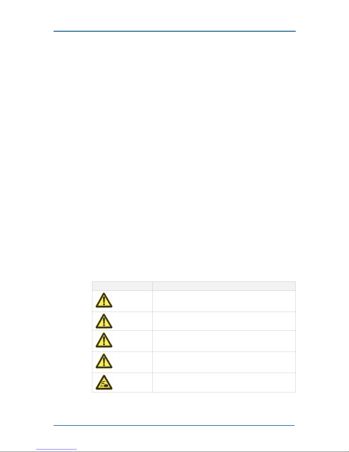
TABLE 3 SAFETY SIGNS
Safety Signs Meaning
Danger: Indicates an imminently hazardous situation, which if
not avoided, will result in death or serious injury. This signal
word should be limited to only extreme situations.
Warning: Indicates a potentially hazardous situation, which if
not avoided, could result in death or serious injury.
Caution: Indicates a potentially hazardous situation, which if not
avoided, could result in minor or moderate injury. It may also
be used to alert against unsafe practices.
Note: Indicates a potentially hazardous situation, which if not
avoided, could result in injuries, equipment damage or
interruption of services.
Erosion: Beware of erosion.
Chapter 1 - Maintenance Security
Confidential and Proprietary Information of ZTE CORPORATION 3
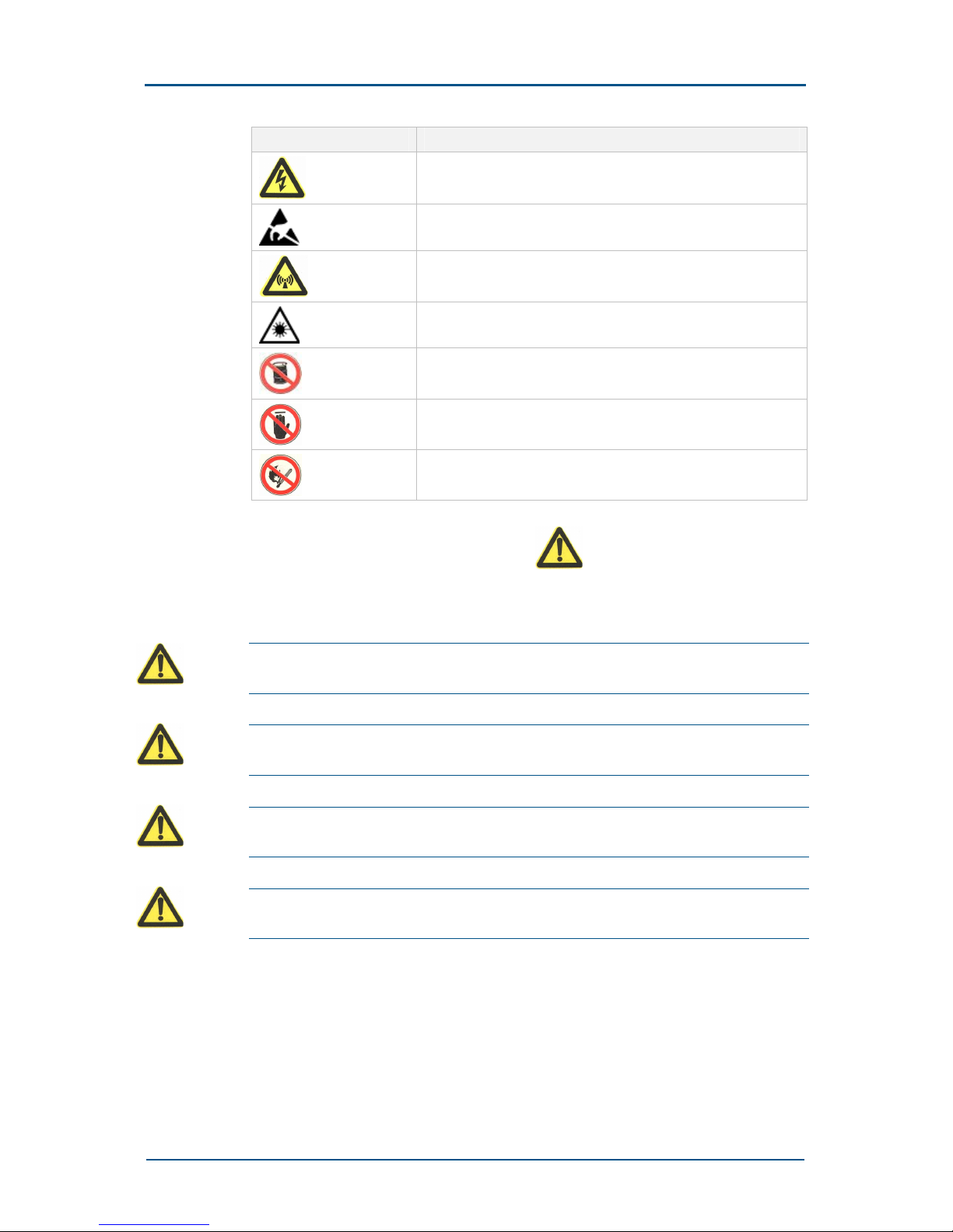
Safety Signs Meaning
Electric shock: There is a risk of electric shock.
Electrostatic: The device may be sensitive to static electricity.
Microwave: Beware of strong electromagnetic field.
Laser: Beware of strong laser beam.
No flammables: No flammables can be stored.
No touching: Do not touch.
No smoking: Smoking is forbidden.
Among them, universal alarm symbol adopts four grades. Based on
the descending order of the danger degree, they are: danger, warning,
caution and notes. Their respective formats and meanings are described
as below.
Danger: This sign means that personal death or major accidents such as
equipment damage or breakdown may occur if you ignore this safety warning.
Warning: This sign means that there may be a major or serious accident,
equipment damage or interruption of key services if you ignore this safety warning.
Caution: This sign means that serious injury or death, equipment damage or
interruption of some services may occur if you ignore this safety warning.
Notes: This sign means that an injury, equipment damage or interruption of local
services may occur if you ignore this safety warning.
To the right of a safety sign is a text indicating its safety level. Under the
sign is the detailed safety description.
ZXG10 BS21 (V2.2) Compact Outdoor BTS for GSM Maintenance Manual
4 Confidential and Proprietary Information of ZTE CORPORATION
Toxic Substances
Beryllia
Warning: Beryllia is a type of toxic chemical existing in the transistor and other
components. The power amplifier circuit and AEM circuit in the base station contain
Beryllia, so it is advised not to touch these components directly under any
circumstances.
Beryllium oxide dusts may be produced when a component containing
beryllium oxide is broken, frictionized or bruised. They may seriously hurt
human skin and membrane even life safety.
Beryllium oxide may hurt human bodies only when components containing
beryllium oxide are damaged. Therefore, be sure to take care when
replacing or handling such components and boards and avoid any
mechanical damage.
Do not discard components containing beryllium oxide randomly. Please
observe local regulations to make chemical treatment or special waste
material treatment for components containing beryllium oxide.
If you suspect that beryllium oxide has entered your skin or been
absorbed in your body, please thoroughly rinse the skin wound with water
and then see the doctor immediately.
The personnel contacting or handing such components should understand
the characteristics of such components and take the corresponding
preventive measures.
Hydrochloride
Warning: Chemicals containing hydrochloride have to be used in some
components of the BS21 (V2.2) device. Burning these components will generate
toxic gas.
Do not burn the components and take preventive measures to avoid
inhaling toxic gas.
Do not discard components containing hydrochloride randomly. Please
observe local regulations to make chemical treatment or special waste
material treatment for components containing hydrochloride.
Chapter 1 - Maintenance Security
Confidential and Proprietary Information of ZTE CORPORATION 5
Electrical Safety
Tools
Warning: Be sure to use special tools rather than common tools for high-voltage
and AC operations.
High Voltage
Danger: High voltage is hazardous. Direct or indirect contact with high voltage or
mains supply through a wet object could result in fatal danger.
Do follow the local safety regulations to install any AC power equipment.
Personnel who that installs AC devices must be qualified for high-voltage
and AC operations.
During operation, it is strictly forbidden to wear any conductive articles
such as watch, chain and ring.
Please prevent water from entering the equipment during operation and
maintenance in damp environments.
Power Cord
Notes: Do not install or remove power cables with power on. Contact of the power
cable with any conductor will generate electric spark or electric arc, which may
cause fire or eye injury.
Do turn off the power supply before connecting or disconnecting a power
cable.
Before connection, make sure the connecting cable and its label suit the
actual installation requirements.
Drilling
Warning: It is not allowed to drill the cabinet without permission.
Unqualified drilling could damage the wiring and cables inside the cabinet.
Additionally, metal pieces inside the cabinet created by the drilling could
result in a shorted circuit board.
When it is necessary to drill holes in the cabinet in some special cases,
please wear insulated protective gloves and move away the cables in the
ZXG10 BS21 (V2.2) Compact Outdoor BTS for GSM Maintenance Manual
6 Confidential and Proprietary Information of ZTE CORPORATION
cabinet before drilling. Take care to protect your eyes during drilling.
Flying metal scraps may harm your eyes. In addition, please promptly
clean and clear metal scraps after drilling.
Thunder
Danger: Operations concerned with high-voltage, AC, iron tower or mast are
strictly forbidden in thunderstorms.
Thunderstorms would give rise to a strong electromagnetic field in the
atmosphere. So, the equipment should be earthed and protected in time
against lightning strike.
Antistatic
Notes: The static electricity produced by the human body could damage the static-
sensitive components on the circuit board, such as large-scale integrated circuits
(IC).
Friction caused by human body’s activities is a source of accumulation of
static charge. When it is dry, the static voltage a human body carries may
be as high as 30kV, and may stay a long while. An operator with static
may cause damage to a device when in touch with it due to the discharge
from the device.
To avoid any damage to sensitive devices by human body static, an
operator should wear an antistatic wrist strap before touching devices,
plug-in boards, circuit boards and IC chips, and well ground the other end
of the antistatic wrist strap.
The cable between the wrist and the ground must be connected in series
with a more than 1M ohm resistance to protect operators from electric
shock. The static discharge from a 1M ohm-plus resistance is sufficiently
low.
Check the antistatic wrist strap regularly. Do not replace the cable of the
wrist strap with any other cable.
Static-sensitive board should not be in touch with any objects carrying
static electricity or easy to generate static electricity. For example, friction
of the package, conveyor box and conveyor belt made of insulation
materials will make the components statically electrified. These
components will discharge static electricity when touching human body or
the ground, thus being damaged.
Static-sensitive boards can only touch high quality discharging materials
such as static-protective packages. Use static-protective packages on
boards during storage and transportation.
Chapter 1 - Maintenance Security
Confidential and Proprietary Information of ZTE CORPORATION 7
Discharge the static electricity before connecting a measurement device
with a board. The measurement device should first be grounded.
Keep boards at least 10cm away from strong DC magnetic fields such as
the cathode-ray tube of a monitor.
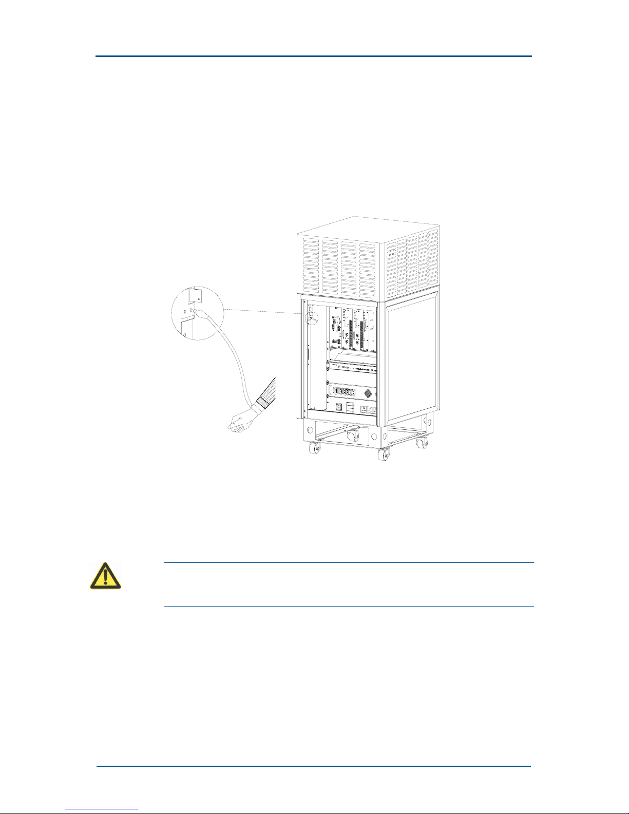
Figure 1 shows how to properly put on antistatic wrist straps.
FIGURE 1 CORRECTLY PUTTING ON ANTISTATIC WRIST STRAP
Storage Battery
If the BS21 is equipped with UPS, please pay due attention to the correct
use and maintenance of storage batteries.
Danger: Before battery-related operations, make sure you have carefully read the
safety precautions on carrying the battery and learned the correct battery
connection method.
Nonstandard operations on the battery will result in great danger. During
operation, short circuit or electrolyte spill/ drain of the batteries must be
prevented, As electrolyte spill will pose potential threat to the equipment
and erode the metal objects and circuit boards, thus damaging the
equipment and causing short circuits to the circuit board.
To ensure safety, please pay attentions to the following points before
battery installation and maintenance:
ZXG10 BS21 (V2.2) Compact Outdoor BTS for GSM Maintenance Manual
8 Confidential and Proprietary Information of ZTE CORPORATION
1. Handle the battery with care. Do not vibrate it violently.
2. Do not wear any object that contains metal, such as watch, chain,
bangle or ring.
3. Use special-purpose insulation tools.
4. Use eye-protecting devices and take preventive measures.
5. Use rubber gloves and aprons that protect against electrolyte overflow.
6. Always keep the front of the pole up during battery transportation. Do
not put it upside down or tilted.
Short Circuit
Danger: Battery short circuit may harm human bodies. Although battery voltage is
generally low, the transient current caused by short circuits will release high
energy.
Prevent metal objects from causing short circuit to the battery, such as
short circuits caused by improper use of operation tools. If allowed, please
first stop battery power supply before making other operations.
Hazardous Gases
Danger: Do not use unsealed LA batteries. Gases released by batteries may burn
or corrode the equipment. Batteries should be fixed and horizontally placed.
Batteries may release inflammable gases during working. Keep sound
ventilation and take fireproof measures where the batteries are placed. To
prevent high temperature caused by exposure to sunlight, windows of the
battery room should be installed with sun shields.
High Temperature
Danger: High temperature may distort and damage the battery or cause overflow
of acid liquid.
If the battery temperature is higher than 60oC, check whether there is any
acid liquid overflow.
If the acid liquid overflows, handle it promptly and properly.
Acid Liquid
Danger: If the acid liquid overflows, promptly and properly absorb and neutralize
the liquid.
Chapter 1 - Maintenance Security
Confidential and Proprietary Information of ZTE CORPORATION 9
When moving a leaking battery, pay attention to potential harms that may
be caused by the acid liquid. Once acid liquid overflow is detected, the
following materials may be used to absorb and neutralize the liquid:
NaHCO
3
, Na2CO3 and Na2CO3-10H2O.
Use manufacturer-recommended materials to absorb and neutralize the
acid liquid.
Storage Battery Replacement
After the storage battery group has run for a long time, its internal
resistance of one or more monomers will increase due to drifting of its
internal parameters. If serious, the monomer becomes an old battery. The
common preventative method and solution to this problem is to recharge
the batter group with high voltage so as to activate its interior. In some
cases, one monomer still cannot be activated after times of recharges, so
it cannot be used any longer and need be replaced.
Since the battery production conditions of different types, batches and by
different manufacturers are different, the internal parameters must be
different too. Therefore, it is required that the monomers of the battery
group should be of the same type, batch and from the same manufacturer
when it is replaced. In this way it is ensured that the parameters are
consistent and the battery group can be used for a long time.
Danger: Operation and maintenance personnel should not replace the specified
batteries with ones of different types. Otherwise, explosions may occur.
Electromagnetic Radiation
Since the antenna of operating equipment generates electromagnetic
radiation, if you are too close to the antenna, your safety may be
endangered. The equipment can be installed and maintained only by
professionals with adequate training and relevant qualifications. The
radiation design of the equipment complies with the IEEE C95.1-1991
standard.
Warning: The high intensity microwave may affect your body health when you
operate on the high-intensity RF equipment.
When close installation and maintenance operations are conducted to a
certain antenna in an iron tower or mast mounted with many transmitter
antennas, collaboration must be prepared so that the transmitter of the
antenna is shut down.
Warning: When conducting installation and servicing operations around the
operating antenna, keep adequate distance from the antenna.
ZXG10 BS21 (V2.2) Compact Outdoor BTS for GSM Maintenance Manual
10 Confidential and Proprietary Information of ZTE CORPORATION
Do not unplug the connector of the transmitter output feeder or of the
antenna feeder cable when the transmitter is operating.
Power off the corresponding transmitter when you need to unplug the
connector of the feeder cable or to work beside the transmitter antenna.
Working at Heights
Warning: When working at heights, take care to prevent objects from falling.
Working at heights should conform to the related national service
regulation requirements:
Operators working at heights must have been specially trained.
Take care of the operation machinery and tools to prevent them from
falling.
Take safety precautions, and wear helmet and safety belt.
In cold areas, wear cold-protection clothes before working at heights.
Before working at heights, check all hoisting equipment.
Hoisting Heavy Objects
Warning: Do not walk about right under the boom and hoisted objected when
heavy objects are hoisted.
When disassembling heavy equipment, or moving and replacing
equipment, make sure there are facilities of proper hoisting capability.
Personnel engaged in the hoisting work must have received relevant
trainings. The tools used for hoisting must have been inspected to ensure
they are tightly fixed on the weight-bearing object or the wall. Use brief
hoisting commands to prevent misoperations.
Using Ladders
Before using ladders, make sure they are in good condition and can be
used through inspection. Over-weight is forbidden during the use of
ladders.
When a ladder tilts more than 5 meters, or a straight two-foot ladder tilts
over 3 meters or when operations are conducted in a dangerous
environment, it is required to have the ladder supported or take other
security measures. A-shape ladders should be fully unfolded when used.
Chapter 1 - Maintenance Security
Confidential and Proprietary Information of ZTE CORPORATION 11
The proper tilt angle for ladders is 75°; the broader foot should always be
put downside or protective measures be taken at the bottom of the ladder
to prevent sliding. Ladders should be put at steady places instead of on
carton boxes, stones or other slippery objects.
Ladder-climbers should face the ladder; when working on tilted ladders,
they should keep their body barycenter within the edges of the ladder. It
is advisable to hold the ladder tightly with one hand and two feet stepping
fast, that is to say, with 3 parts of the body in contact with the ladder to
ensure security and reduce risks. It is suggested that the last 4 rails
should be left un-mounted as the limit of the climbing height. If work need
be carried out on the roof, the ladder should be at least 1 meter higher
than the eaves against which the ladder leans.
Fans
Warning:
Keep your fingers or body off any dangerous parts of the fan that is still
running.
Make sure not to stick your fingers or any tool into the running fan in case any
damage or injury done to the device or the human body.
While replacing the related parts, be sure to put away the parts, screws
and tools. Make sure they will not fall into the working fan and damage the
fan or related devices.
When replacing the devices around the fan, do not put your finger or a
board in the fan, to avoid damage to the equipment or your finger.
High Temperature
Warning: The surface temperature of some devices is quite high, so do not touch
them in case of being scalded.
Board Plugging/Unplugging
Notes:
Never plug a board too hard, so as not to deform the pins on the backplane.
Plug a board along the slot to avoid short circuit due to touch with the circuit of
the adjacent board.
ZXG10 BS21 (V2.2) Compact Outdoor BTS for GSM Maintenance Manual
12 Confidential and Proprietary Information of ZTE CORPORATION
When holding a board, keep your hands off the board circuit, components,
connectors and cable trough.
Do-Nots
Notes: Do not perform maintenance or debugging inside the equipment, unless a
qualified person is present for your help.
Replacing any parts or altering the equipment might result in unexpected
danger. Therefore, be sure not to replace any parts or alter the equipment
unless otherwise authorized.
To ensure your safety, if you have any question, please contact ZTE
Corporation.

Confidential and Proprietary Information of ZTE CORPORATION 13
Chapter 2
Maintenance Overview
In this chapter, you will learn about:
Categories of daily maintenance
Common maintenance methods
Precautions on daily maintenance

ZXG10 BS21 (V2.2) Compact Outdoor BTS for GSM Maintenance Manual
14 Confidential and Proprietary Information of ZTE CORPORATION
Categories of Daily Maintenance
Daily maintenance of the BS21 (V2.2) device can be divided into routine
maintenance, handling of notification information and alarm information as
well as troubleshooting.
1. Routine maintenance
Routine maintenance refers to daily and periodic maintenance to check
the running conditions of the equipment periodically and handle faults
in time. The routine maintenance is intended to find hidden troubles,
prevent accidents, locate faults in time and handle faults as early as
possible.
2. Notification information handling
Notification information handling refers to a process ranging from the
analysis of various notification messages arising from the running of
the system, judgment on whether there is anything abnormal to
appropriate handling.
3. Alarm information handling
Alarm information handling refers to the process ranging from the
analysis of various alarm messages that occur during the running of
the system, judgment on whether there is anything abnormal to
appropriate handling.
4. Troubleshooting
Troubleshooting is a process of analyzing, handling and resolving any
fault that is discovered.
Common Maintenance Methods
Some methods need to be adopted to locate faults during daily
maintenance. The common maintenance methods are as follows:
1. Alarm and operation log view
Alarm and operation log view is the first method to be adopted when a
fault is detected by maintenance personnel. It is implemented through
the alarm management and operation log view interface of the BSS
operation & maintenance subsystem OMCR.
Through the alarm management interface, we can observe and analyze
alarm messages reported from each NE such as the current alarm,
history alarm and general notification. In this way, we can detect any
fault during network running in time and then locate, isolate and
remove it.
By viewing operation logs in user management, we can investigate
modifications on system parameters, locate the relevant responsible
terminal and operator as well as detect faults caused by individual
operations in time.

Chapter 2 - Maintenance Overview
Confidential and Proprietary Information of ZTE CORPORATION 15
2. Indicator status analysis
Indicator status analysis is a frequently adopted method when a fault
is detected by maintenance personnel. With this method, we can locate
and remove faults by observing the indicator status on each board
panel in the rack.
This method requires maintenance personnel to be familiar with the
indicator status and meaning of each board.
3. Performance analysis
It is implemented through the performance management interface of
the BSS operation & maintenance subsystem OMCR. Through this
interface, maintenance personnel can implement performance
management and signaling tracing on the BSS system.
Through the performance management interface, users can create all
kinds of performance measurement tasks, product various
performance reports and grasp the performance indexes of the BSS
system, such as the traffic of each cell, congestion situation of SDCCH
and TCH, successful and failed switchover. By analyzing such
information, maintenance personnel can discover load allocation
situation in the network in time so as to adjust network parameters to
enhance network performances.
Through the signaling tracing interface, we can trace signaling involved
in BSS (including Gb interface signaling), thus facilitating consulting of
different signaling flows in the debugging and maintenance processes
as well as detecting problems in the signaling cooperation process.
4. Analyzing with instruments and meters
This method allows maintenance personnel to locate, analyze and
remove faults with the testing mobile, frequency spectrograph,
signaling analyzer, power meter and site master during base station
maintenance.
5. Plugging and pressing
When detecting a board fault, we can loosen the fixation screw in the
front panel and plug or unplug the board and external interface
connector. In this way, we can remove faults caused by poor contact
or processor faults.
In addition, we can also remove faults caused by poor contact by
pressing the cable connector after power-off.
6. Comparing and swapping
Comparing indicates to compare a possible faulty board with a board at
the similar position in the system (for example: a board at the same
slot in a multi-module system) from aspects such as the running status,
jumper and connection cables. We can judge whether the board fails
through comparison.
Swapping indicates to replace a possible faulty board with a standby
part or another board of the same type running normally in the system.
We can judge whether the board actually fails according to whether the
fault disappears after board replacement. It should be noted that no
matter the comparison or replacement method is adopted, the board

ZXG10 BS21 (V2.2) Compact Outdoor BTS for GSM Maintenance Manual
16 Confidential and Proprietary Information of ZTE CORPORATION
unplugging/plugging operation should be performed in accordance with
the relevant description in Appendix
A of this manual.
7. Isolating
When a part of the system fails, it can be isolated from other relevant
boards or racks to judge whether the fault is caused by mutual
influence. For example, the often-used isolating method is to remove
CMM module or transmission faults by self-looping the E1 interface of
the CMM module.
8. Self-test method
It refers to fault judgment through self-test after the system or module
is powered on again. Generally, by powering on common modules for
self-test, we can find the indicators on the panel will flash regularly,
from which we can judge whether there are any problems in the
modules.
Generally, during actual operation, the above methods and accumulated
experiences of maintenance personnel are combined to remove faults in
the maintenance process.
Precautions on Daily
Maintenance
Please pay attention to the following points during daily maintenance:
1. Normal temperature, humidity and a clean and tidy environment
should be kept for the equipment room, and the equipment room
should be dampproof and free of dust, rodents and insects.
2. The primary power of the system should be stable and reliable.
Periodic check should be performed on the system ground and
lightning-protection ground. Especially before thunderstorm seasons
and after thunderstorms, the lightning-protection system should be
checked to guarantee that the facilities are in sound conditions.
3. A perfect equipment room maintenance system should be formulated
to standardize daily work of the maintenance personnel. Detailed logs
should be prepared to record the daily running, version, data change,
upgrade and troubleshooting of the system for the convenience of fault
analysis and handling. In addition, shift records should be made to
differentiate individual responsibilities.
4. It is prohibited to play online games or surf on the Internet at the PC
terminal or install, operate or copy any software irrelevant to the
system in the PC terminal. It is forbidden to use PC terminals for other
purposes.
5. Right-based NMS (Network Management System) passwords should be
set, managed strictly and modified periodically. Such passwords are
available to the maintenance personnel only.
 Loading...