

Zte NetNumen U31 R06 Hardware Installation Manual

NetNumen™U31R06
UniedElementManagementSystem
HardwareInstallationGuide
Version:V12.14.30
ZTECORPORATION
No.55,Hi-techRoadSouth,ShenZhen,P .R.China
Postcode:518057
Tel:+86-755-26771900
Fax:+86-755-26770801
URL:http://support.zte.com.cn
E-mail:support@zte.com.cn

LEGALINFORMATION
Copyright©2014ZTECORPORATION.
Thecontentsofthisdocumentareprotectedbycopyrightlawsandinternationaltreaties.Anyreproductionor
distributionofthisdocumentoranyportionofthisdocument,inanyformbyanymeans,withoutthepriorwritten
consentofZTECORPORATIONisprohibited.Additionally,thecontentsofthisdocumentareprotectedby
contractualcondentialityobligations.
Allcompany,brandandproductnamesaretradeorservicemarks,orregisteredtradeorservicemarks,ofZTE
CORPORATIONoroftheirrespectiveowners.
Thisdocumentisprovided“asis”,andallexpress,implied,orstatutorywarranties,representationsorconditions
aredisclaimed,includingwithoutlimitationanyimpliedwarrantyofmerchantability,tnessforaparticularpurpose,
titleornon-infringement.ZTECORPORATIONanditslicensorsshallnotbeliablefordamagesresultingfromthe
useoforrelianceontheinformationcontainedherein.
ZTECORPORA TIONoritslicensorsmayhavecurrentorpendingintellectualpropertyrightsorapplications
coveringthesubjectmatterofthisdocument.ExceptasexpresslyprovidedinanywrittenlicensebetweenZTE
CORPORATIONanditslicensee,theuserofthisdocumentshallnotacquireanylicensetothesubjectmatter
herein.
ZTECORPORA TIONreservestherighttoupgradeormaketechnicalchangetothisproductwithoutfurthernotice.
UsersmayvisittheZTEtechnicalsupportwebsitehttp://support.zte.com.cntoinquireforrelatedinformation.
TheultimaterighttointerpretthisproductresidesinZTECORPORATION.
RevisionHistory
RevisionNo.RevisionDateRevisionReason
R1.02014-12-20Firstedition
SerialNumber:SJ-20141121 113158-006
PublishingDate:2014-12-20(R1.0)
SJ-20141121113158-006|2014-12-20(R1.0)ZTEProprietaryandCondential

Contents
Chapter1InstallationFlow........................................................................1-1
Chapter2InstallationPreparations..........................................................2-1
2.1EnvironmentCheck............................................................................................2-1
2.2T oolsPreparation...............................................................................................2-2
2.3RequiredDocuments..........................................................................................
Chapter3UnpackingandCheckingEquipment.....................................
Chapter4RemovingCabinetDoors.........................................................4-1
Chapter5CabinetInstallation...................................................................5-1
5.1InstallingtheCabinetontheAdjustableBase.......................................................5-2
5.2InstallingtheCabinetontheFloor.....................................................................
Chapter6InstallationofExternalPowerCablesandGrounding
Cables.....................................................................................................
6.1PowerSupplySystemofaCabinet......................................................................6-1
6.2CablingRequirements........................................................................................6-3
6.3InstallingPowerCablesandGroundingCables....................................................
Chapter7AssemblyInstallationinaCabinet..........................................
7.1InstallinganE4140Shelf....................................................................................7-1
7.2InstallingBoards................................................................................................
7.2.1RemovingaBlankPanel...........................................................................7-4
7.2.2InstallingaBoard.....................................................................................7-6
2-5
3-1
5-18
6-1
6-7
7-1
7-3
Chapter8InstallationofInternalPowerCablesandGrounding
Cables.....................................................................................................8-1
8.1PowerSupplySysteminaCabinet......................................................................8-1
8.2InstallingCablesforanE4140Shelf....................................................................8-3
Chapter9SignalCableInstallation..........................................................9-1
9.1SignalCableInstallationRequirements................................................................9-1
9.2SettingJumpersandDIPSwitchesoftheUniedPDU........................................
9.3InstallingtheNetworkCables..............................................................................9-8
Chapter10CabinetAccessoryInstallation............................................10-1
10.1InstallingtheCabinetSideDoor......................................................................10-1
10.2InstallingtheFrontandRearDoors.................................................................10-3
Chapter11PeripheralDeviceInstallation..............................................11-1
I
SJ-20141121113158-006|2014-12-20(R1.0)ZTEProprietaryandCondential
9-4

11.1InstallingTerminalDevices...............................................................................11-1
11.2AlarmBoxInstallation......................................................................................11-2
11.2.1InstallingtheAlarmBox.........................................................................11-2
11.2.2ConnectingCables(ACPowerSupply)...................................................
11.2.3ConnectingCables(DCPower)..............................................................11-6
11-4
Chapter12InstallationInspection..........................................................12-1
12.1CheckingtheCabinets....................................................................................12-1
12.2CheckingtheAssembliesintheCabinets.........................................................12-2
12.3CheckingthePowerCablesandGroundingCables..........................................
12.4CheckingtheSignalCables............................................................................12-3
12.5CheckingtheOtherauxiliaryDevices...............................................................
Chapter13SystemPower-On.................................................................
13.1PoweringontheCabinet.................................................................................13-1
13.2PoweringontheE4140Shelves......................................................................
Chapter14SiteClean-Up.........................................................................
12-2
12-3
13-1
13-3
14-1
AppendixAMakingaPowerCableandaGroundingCable.................A-1
AppendixBMakingaNetworkCable......................................................
B-1
Figures.............................................................................................................I
Tables.............................................................................................................V
Glossary.......................................................................................................VII
II
SJ-20141121113158-006|2014-12-20(R1.0)ZTEProprietaryandCondential

Chapter1
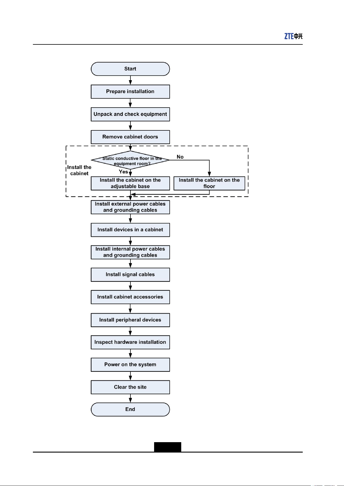
InstallationFlow
Beforestartinghardwareinstallation,youshallcompletecorrespondingpreparations,such
aspreparingconstructionconditions,checkinginstallationenvironment,andunpacking
andinspectinggoods,sothatthelaterinstallationprocesscanbesmoothandefcient.
Forthehardwareinstallationow,seeFigure1-1.
1-1
SJ-20141121113158-006|2014-12-20(R1.0)ZTEProprietaryandCondential
NetNumen™U31R06HardwareInstallationGuide
Figure1-1HardwareInstallationFlow
1-2
SJ-20141121113158-006|2014-12-20(R1.0)ZTEProprietaryandCondential

Chapter2
InstallationPreparations
Youmustknowtheprocedureforinstallingthehardware,andhaveknowledgeonsystem
networkstructure,powersupply,cableconnection,andhardwaremaintenance.
Beforeinstallation,youneedtochecktheenvironmentandpreparerequiredtoolsand
documents.
TableofContents
EnvironmentCheck....................................................................................................2-1
ToolsPreparation.......................................................................................................
RequiredDocuments..................................................................................................2-5
2.1EnvironmentCheck
Beforeinstallation,itisnecessarytochecktheequipmentroomtoensurethatthe
environmentmeetstheoperatingrequirementsoftheequipment.
2-2
Note:
Itisnotallowedtoinstalltheequipmentiftheinstallationenvironmentisunsatisfactory.
lArchitecturalconditions
Checkthesize,height,load-bearingcapacity,andlayoutoftheequipmentroom.
lEnvironmentalconditions
Checkillumination,air-conditioning,ventilation,antistaticmeasures,shockproof
measures,lightningprotectionmeasures,andre-ghtingdevicesoftheequipment
room.
lPowersupplyconditions
CheckACpowersupplyfacilities,DCpowersupplyfacilities,andaccumulator
batteries.
lGroundingconditions
Theequipmentroommusthavegoodgroundingconditions.Groundresistancemust
meetlocaltechnicalrequirements.Ingeneral,groundresistancecannotbegreater
than1Ω.
lAuxiliarydevices
2-1
SJ-20141121113158-006|2014-12-20(R1.0)ZTEProprietaryandCondential
NetNumen™U31R06HardwareInstallationGuide
CheckDigitalDistributionFrames(DDF),cabletrays,andcabledistributionframes.
lOtherfacilities
Checkworkbenches,poweroutlets,alarmboxes,andotherperipheraldevices.
Foradetailedenvironmentalchecklist,refertoEnvironmentAcceptanceReportofCore
NetworkProducts.
2.2ToolsPreparation
Foralistofthetoolsandmetersthatmustbepreparedbeforeinstallation,refertoT able
2-1.
Note:
Instrumentsandmetersaresubjecttolocalstandards.Thepicturesinthetablearefor
referenceonly.
Themeterscannotbeusedunlessstrictlycalibratedandprovenqualied.
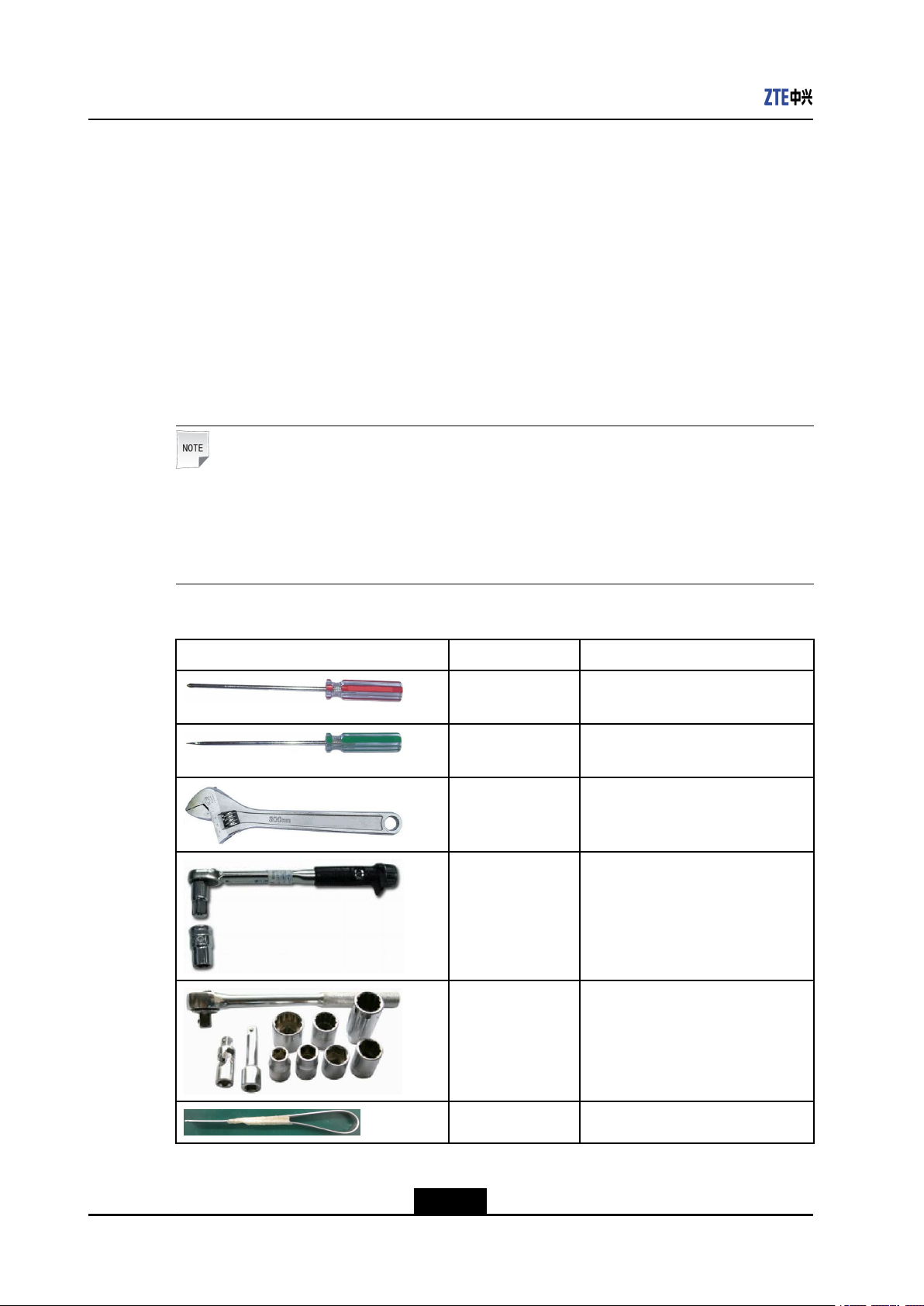
Table2-1ToolsandMeters
PictureNamePurpose
Crossheadscrew-
driver
Flatheadscrew-
driver
AdjustablewrenchTightensbolts.
TorquewrenchTightensbolts.
SocketwrenchsetLoosensortightensfastenerstoad-
Tightenscrossheadscrews.
Tightensatheadscrews.
justthelevelofthecabinet.
Floating-nutdriverInstallsoatingnuts.
2-2
SJ-20141121113158-006|2014-12-20(R1.0)ZTEProprietaryandCondential
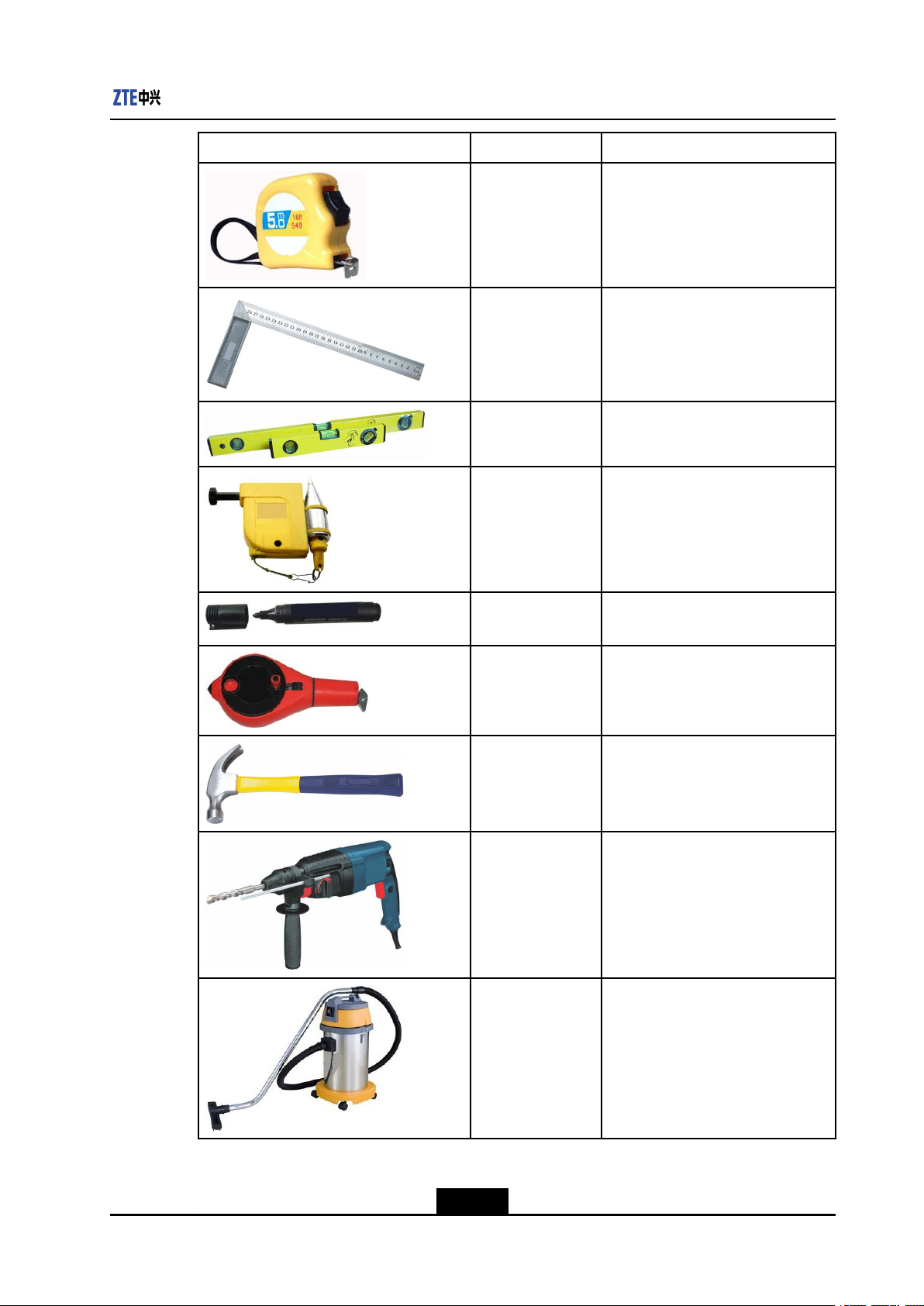
PictureNamePurpose
TapemeasureMeasureslength.
AnglesquareMeasureslengthordrawsrightan-
SpiritlevelChecksthelevelofadjustable
PlumblineChecksverticaldeviationofacabi-
Chapter2InstallationPreparations
gles.
basesandcabinets.
net.
MarkerpenMarksthepositionsofdrilledholes
ontheoor.
PowdermarkerMarkslinesonthegroundtode-
terminethepositionwhereasocket
boltisinstalled.
ClawhammerInstallssocketboltsandopens
woodencases.
PercussiondrillDrillsholes.
VacuumcleanerCleansinstallationholesandthe
oor.
2-3
SJ-20141121113158-006|2014-12-20(R1.0)ZTEProprietaryandCondential
NetNumen™U31R06HardwareInstallationGuide
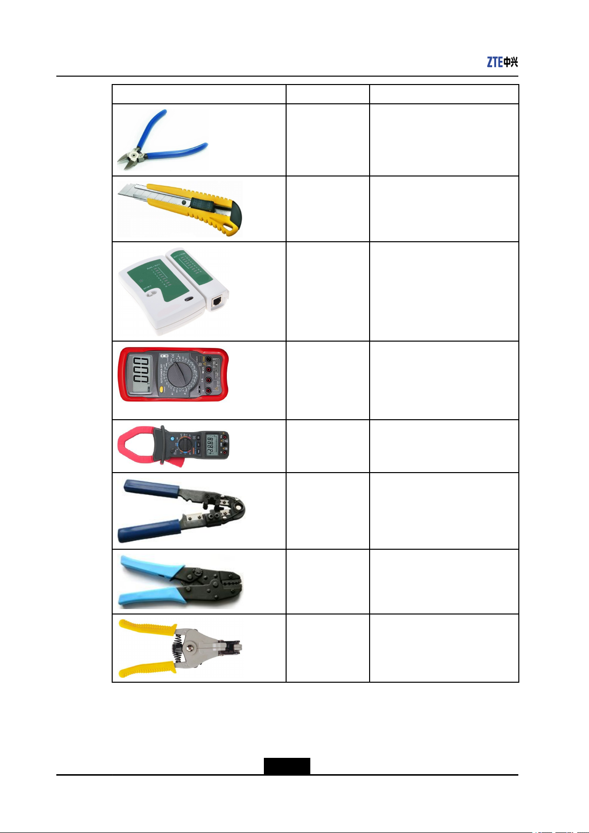
PictureNamePurpose
DiagonalpliersPrunescabletiesandcutspacking
strapsofcartons.
PaperknifeCutsadhesivetapesoncartons.
Networkcable
Testsnetworkcables.
tester
MultimeterT eststheinsulationconditionofcab-
inets,connectionconditionofca-
bles,andelectricperformancein-
dexesofdevices,suchasvoltage,
current,andelectricresistance.
Currentclampme-
ter
Measuresthecurrentinacableun-
dertheconditionthattheloadingop-
erationisnotinterrupted.
Crystalheadcrimp-
ingpliers
Crimpscrystalheadsofnetworkca-
bles.
Coaxial-cable
crimpingpliers
Crimpsthemetalsheathattheend
ofacoaxialcable.
WirestrippersStripsoffthecablesheath.
2-4
SJ-20141121113158-006|2014-12-20(R1.0)ZTEProprietaryandCondential
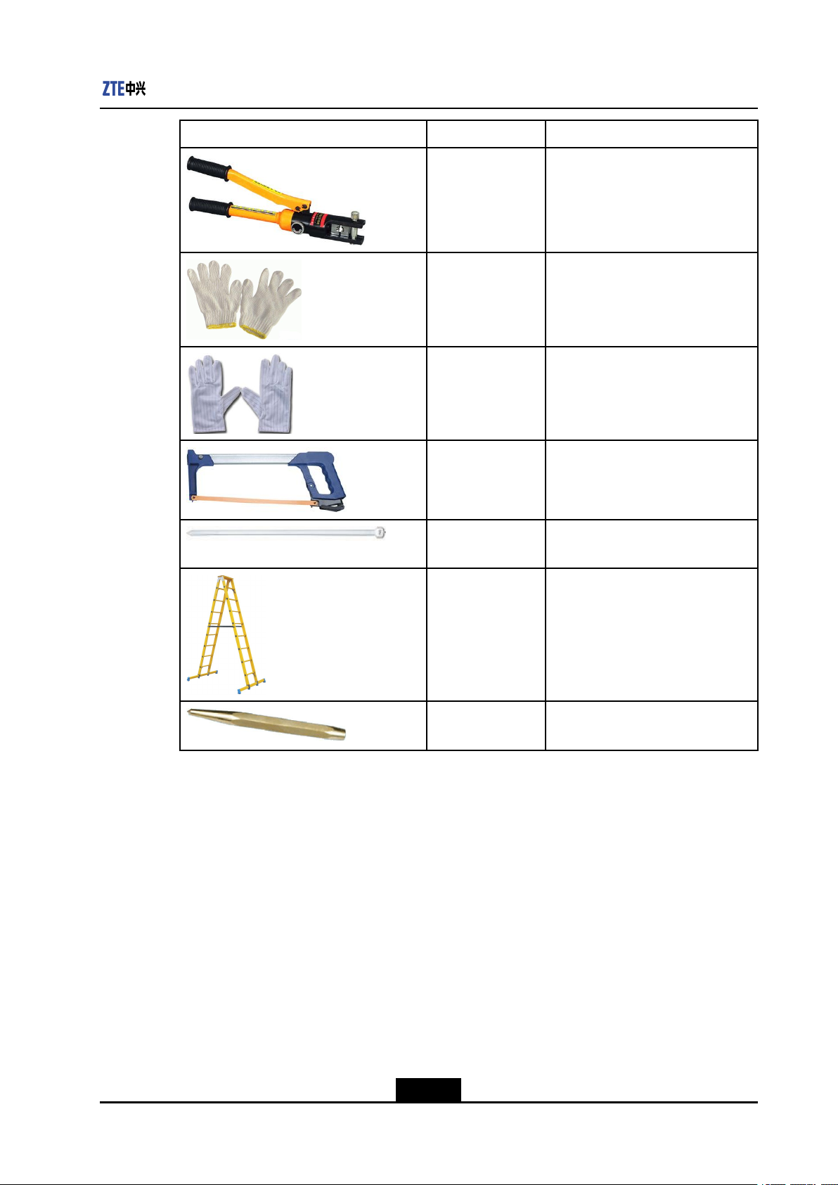
PictureNamePurpose
HydraulicpliersCrimpsO-typeterminalsandJGter-
WorkglovesUsedduringinstallation.
Anti-staticglovesUsedduringinstallation.
HacksawCutswoodoorormetal.
Chapter2InstallationPreparations
minals.
2.3RequiredDocuments
CabletieTiesuppowercables,protective
groundingwires,andsignalcables.
LadderUsedforworkingatheights.
PunchUsedtolocateadrillbitformaking
anindentationattheholelocation.
Thefollowingdocumentsmustbepreparedbeforeinstallation:
lEngineeringdesigndocumentsandpackinglists
lManualsshippedwiththeproducts
lUnpackingInspectionGuideofCoreNetworkProducts
lEnvironmentAcceptanceReportofCoreNetworkProducts
lCoreNetworkProductHardwareInstallationQualityStandard
2-5
SJ-20141121113158-006|2014-12-20(R1.0)ZTEProprietaryandCondential

NetNumen™U31R06HardwareInstallationGuide
Thispageintentionallyleftblank.
2-6
SJ-20141121113158-006|2014-12-20(R1.0)ZTEProprietaryandCondential

Chapter3
UnpackingandChecking
Equipment
Thisproceduredescribeshowtounpackwoodencases,cartons,andtheboardpackage.
Forhowtocountandcheckequipment,refertoUnpackingInspectionGuideofCore
NetworkProducts.
lAwoodencaseisusedtopackacabinet.
lAcartonisusedtopackboards,terminalequipment,andcables.
Prerequisite
Aatheadscrewdriver,aclawhammer,diagonalpliers,apaperknife,antistaticgloves(or
anESDwriststrap)areready .
Steps
1.CheckthetotalnumberofequipmentinaccordancewiththePackingList,andthen
verifythattheouterpackingiscomplete.
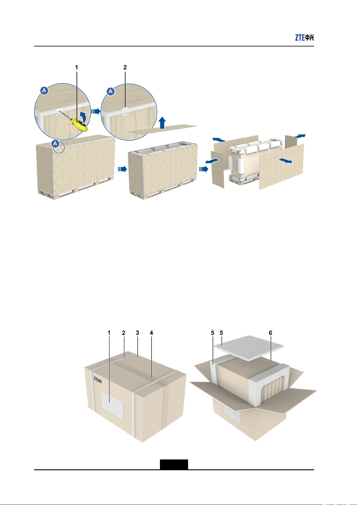
2.Removetheouterpackingofthewoodencase.
a.Movethewoodencasewithaforktrucktothecabinetinstallationsiteinthe
equipmentroom.
b.Openalltonguepieceswithaatheadscrewdriver,removetheuppercoverofthe
case,andthenremovethesideboards,seeFigure3-1.
3-1
SJ-20141121113158-006|2014-12-20(R1.0)ZTEProprietaryandCondential
NetNumen™U31R06HardwareInstallationGuide
Figure3-1UnpackingaWoodenCase
1.Flatheadscrewdriver2.Tongue
c.Takeouttheequipmentlist,technicaldocuments,andtoolsforequipment
installationfromPackage1.
d.Makethebottomofthecabinetdownwards.
e.Removefoamcornerprotectors,foamedgeprotectors,andplasticpackage.
3.Removetheouterpackingofthecarton,seeFigure3-2.
a.Cutthepackingstrapsofacartonbyusingdiagonalpliers.
b.Cuttheadhesivetapessealingthecarton.
c.Openthecarton,andthentakeoutthefoamboardandboardboxes.
Figure3-2RemovingtheOuterPackingofaCarton
1.Cartonlabel2.Packingstrap3.Carton
3-2
SJ-20141121113158-006|2014-12-20(R1.0)ZTEProprietaryandCondential
Chapter3UnpackingandCheckingEquipment
4.Adhesivetape5.Foamboard6.Boardbox
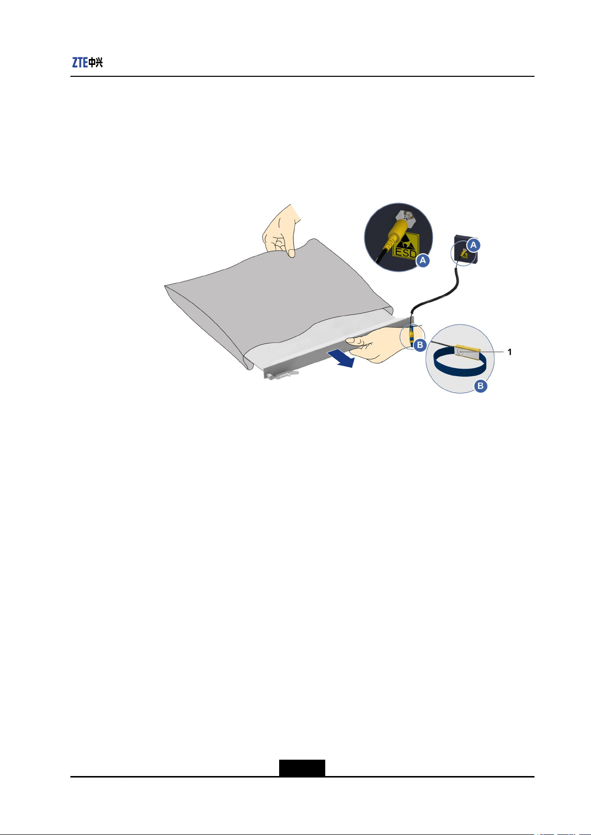
4.Removetheboardpackage.
a.Wearantistaticgloves(oranESDwriststrap).
b.Removetheboardpackage,seeFigure3-3.
Figure3-3RemovingtheBoardPackage
1.ESDwriststrap
c.Fortheboardthatisnotinstalledimmediately,putitbackinitsoriginalpackage,
andthensealthepackage.
5.Checktoensurethattheequipmentisingoodconditionandthequantityiscorrect
beforeequipmenthand-overandstorage.
–EndofSteps–
3-3
SJ-20141121113158-006|2014-12-20(R1.0)ZTEProprietaryandCondential

NetNumen™U31R06HardwareInstallationGuide
Thispageintentionallyleftblank.
3-4
SJ-20141121113158-006|2014-12-20(R1.0)ZTEProprietaryandCondential
Chapter4
RemovingCabinetDoors
Thecabinetisdeliveredwithfrontandreardoorsinstalled.Tofacilitateinstallationofthe
accessoriesinthecabinet,youneedtoremovethefrontandreardoors.Thisprocedure
describeshowtoremovethecabinetdoors.
Note:
Thefrontdoorandthereardoorcanberemovedinthesameway.Removingthefront
doorisusedasanexampleinthisprocedure.
Prerequisite
Acrossheadscrewdriverisready.
Steps
1.Openthedoorlock,andthenopenthecabinetdoor,seeFigure4-1.
Figure4-1OpeningtheDoorLock
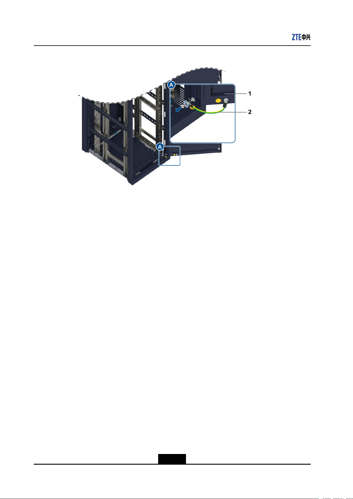
2.Disconnecttheendofthegroundingcableonthecabinetbyusingacrosshead
screwdriver(itisrecommendedthatonlytheendconnectedtothecabinetis
disconnected),seeFigure4-2.
4-1
SJ-20141121113158-006|2014-12-20(R1.0)ZTEProprietaryandCondential
NetNumen™U31R06HardwareInstallationGuide
Figure4-2DisconnectingtheGroundingCable
1.Cabinetdoor2.Groundingcable
3.Installthescrewsbacktothecabinettoavoidlosingthem.
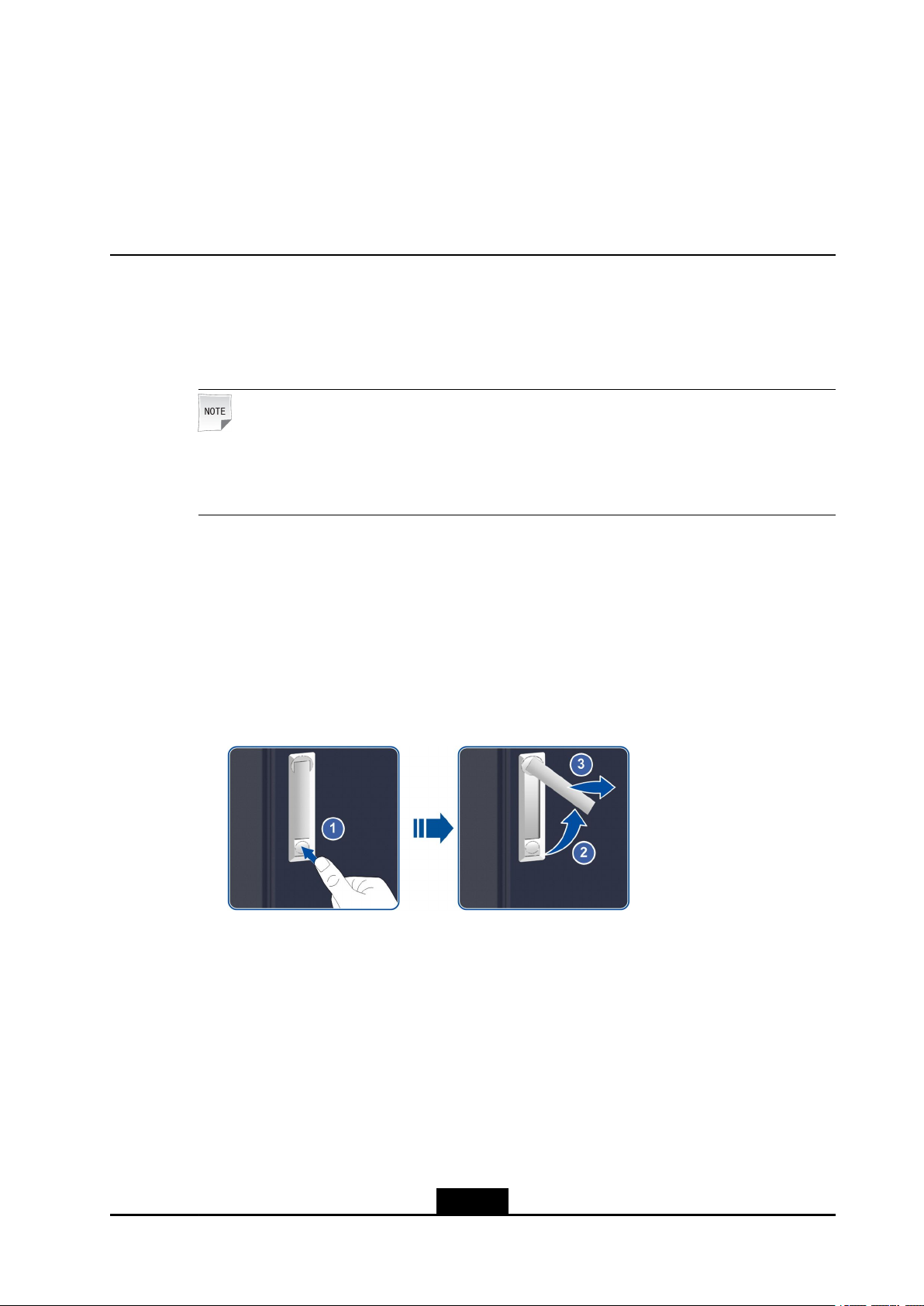
4.Disassemblethecabinetdoor,seeFigure4-3.
a.Holdthedoorwithyourrighthand.
b.Pulldownthespringpinlocatedinthemiddlepartofthedoorwithyourlefthand,
andthenhangthespringpininthegapononesideofthedoor.
c.Pulldownthespringpinontheupperpartofthedoor.
d.Liftthedoorupwards,andthenmovethedooroutwards.
4-2
SJ-20141121113158-006|2014-12-20(R1.0)ZTEProprietaryandCondential
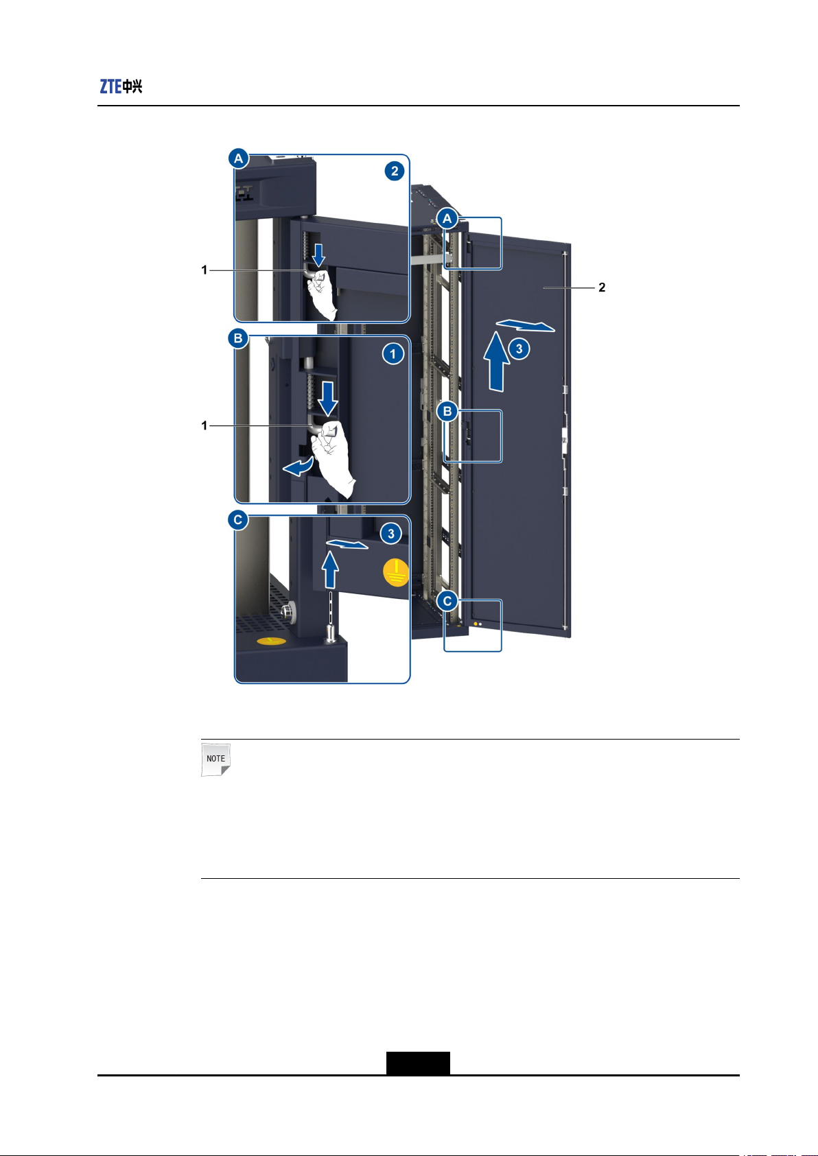
Figure4-3DisassemblingtheCabinetDoor
Chapter4RemovingCabinetDoors
1.Springpin2.Frontdoor
Note:
Putthecabinetatasafeplace.
Ensurethatthelockofthecabinetdoorisopened,whichpreventsthelockrodonthe
lowerpartofthedoorfrombeingdistortedbecauseofpressure.
–EndofSteps–
4-3
SJ-20141121113158-006|2014-12-20(R1.0)ZTEProprietaryandCondential

NetNumen™U31R06HardwareInstallationGuide
Thispageintentionallyleftblank.
4-4
SJ-20141121113158-006|2014-12-20(R1.0)ZTEProprietaryandCondential
Chapter5
CabinetInstallation
Forselectingthecabinetinstallationmodeinaccordancewiththeequipment-room
conditions,refertoT able5-1.
Table5-1SolutionsforInstallingtheCabinet
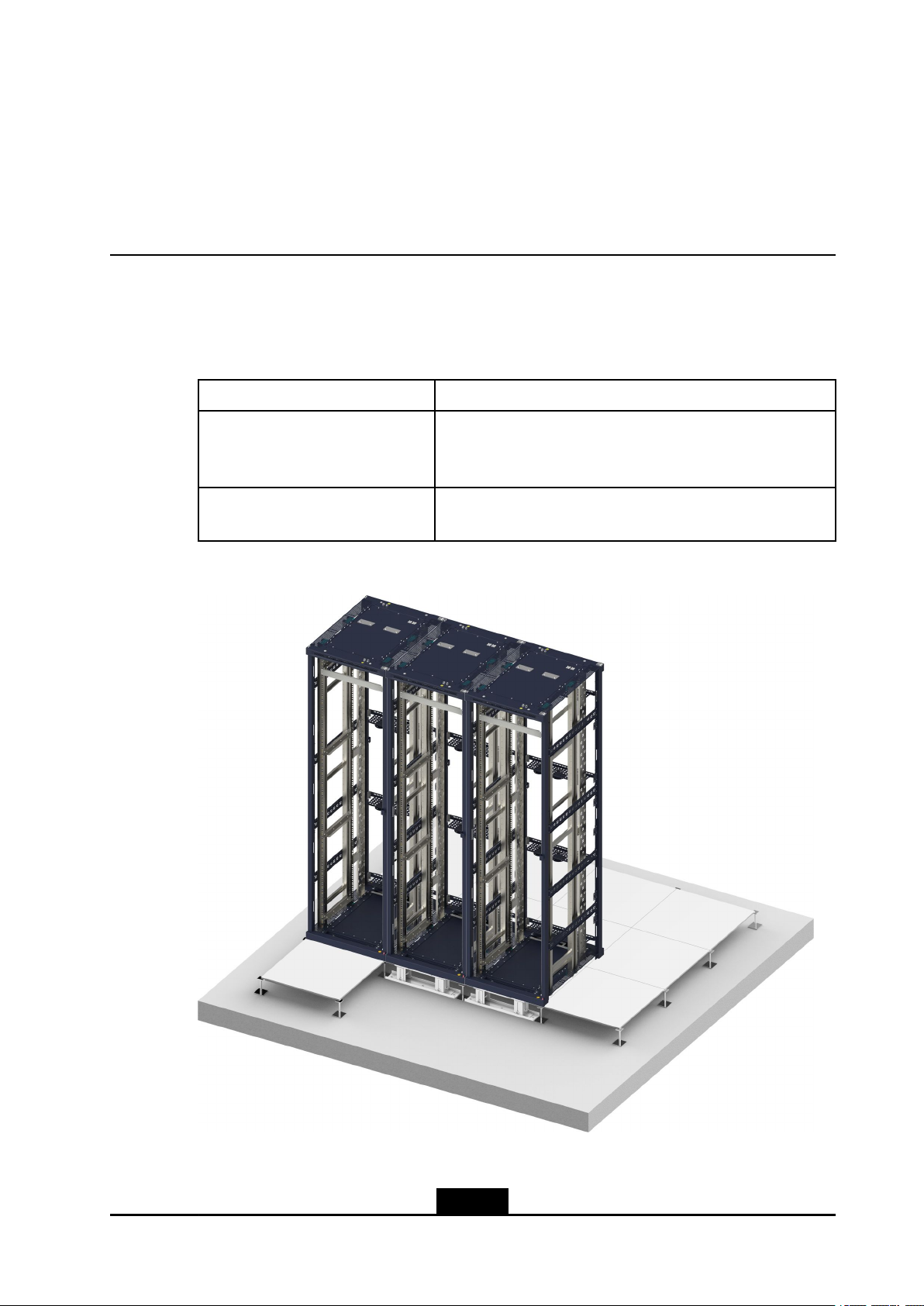
EquipmentRoomConditionInstallationSolution
Theequipmentroomhasstatic
conductiveoor.
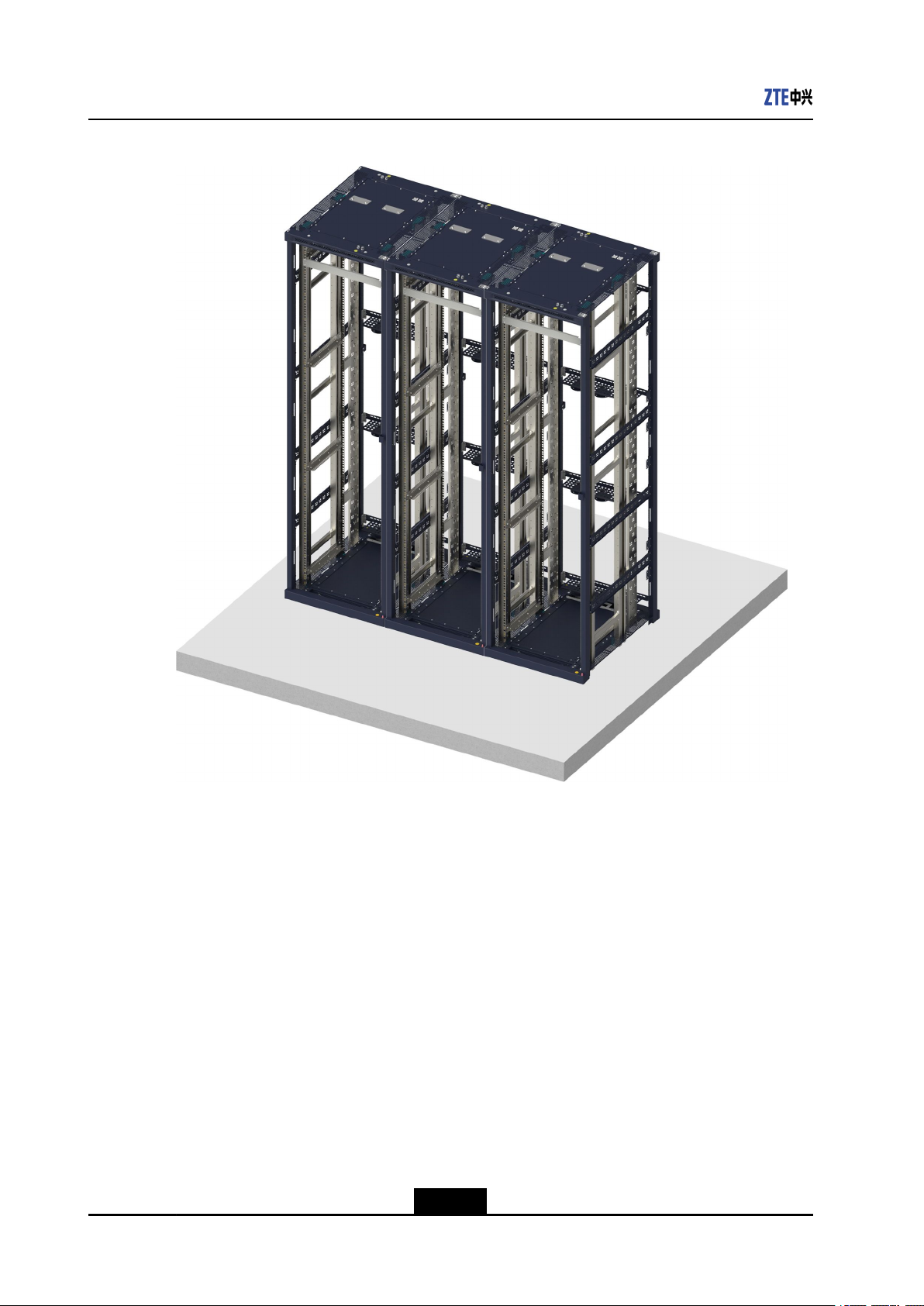
Theequipmentroomhasnostatic
conductiveoor.
Figure5-1InstallingtheCabinetontheAdjustableBase
Installthecabinetontheadjustablebase.Usetheadjustable
basetoinstallthecabinetontheconcreteoorofthe
equipmentroom,seeFigure5-1.
Installthecabinetontheoor.Installthecabinetdirectlyon
theconcreteooroftheequipmentroom,seeFigure5-2.
5-1
SJ-20141121113158-006|2014-12-20(R1.0)ZTEProprietaryandCondential
NetNumen™U31R06HardwareInstallationGuide
Figure5-2InstallingtheCabinetontheFloor
TableofContents
InstallingtheCabinetontheAdjustableBase.............................................................5-2
InstallingtheCabinetontheFloor............................................................................5-18
5.1InstallingtheCabinetontheAdjustableBase
Thisproceduredescribeshowtoinstallthecabinetontheadjustablebase.
Adjustthebaseheightandmountthebasetomakeitssurfaceinlevelwiththestatic
conductiveoor.
5-2
SJ-20141121113158-006|2014-12-20(R1.0)ZTEProprietaryandCondential

Chapter5CabinetInstallation
Note:
Ensurethattheengineeringoverthecabinet(suchascabletrayinstallation)iscompleted,
sothatdustormetalscrapswillnotdropintothecabinetfromthetopduringthecabinet
installationprocess.
Prerequisite
lTherelateddesigndocumentsareready.
lThedrillingtemplate(providedwiththecabinet)isready.
lTheadjustablebases,AN01socketboltsareready.
lInstrumentssuchascrossheadscrewdriver,tapemeasure,anglesquare,spiritlevel,
powdermarker,markerpen,percussiondrill,vacuumcleaner,adjustablespanner,
torquespanner,socketspanner,clawhammer,punch,multimeter,andladderare
ready.
lSpacershims,insulatinggaskets,M12×90bolts(anM12×90boltcontainsaspring
washer,agasket,andaninsulatingwasher),M12×35bolts(anM12×35boltcontains
aspringwasherandagasket)areready.
Context
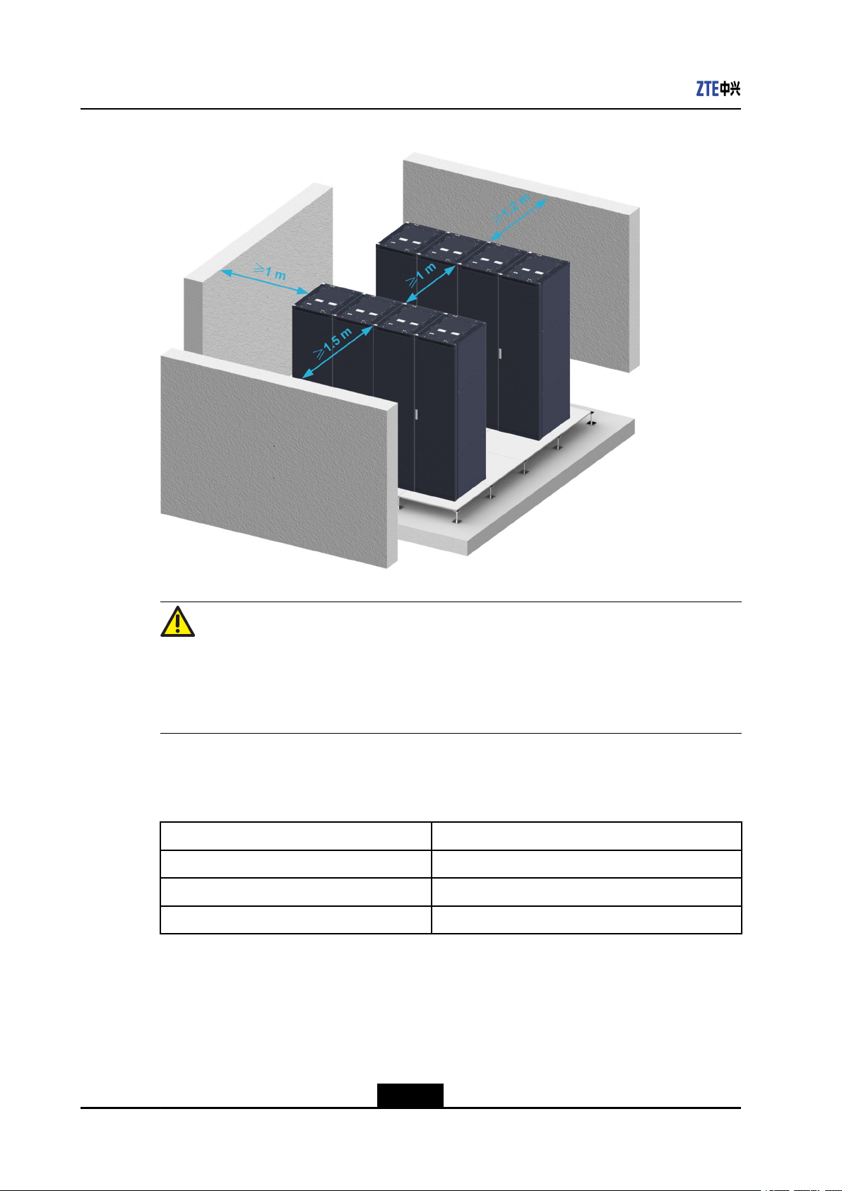
Fortheinstallationpositionofthecabinetintheequipmentroom,seeFigure5-3.
5-3
SJ-20141121113158-006|2014-12-20(R1.0)ZTEProprietaryandCondential
NetNumen™U31R06HardwareInstallationGuide
Figure5-3InstallationPositionoftheCabinet
Caution!
Themountingpositionoftheadjustablebaseshouldnotconictwiththeframeworkof
thestaticconductiveoor.Ifacollisionisunavoidable,removetheoorframeworkatthe
collidingposition.
Adjustablebasesfallintothreetypes.Fortypesoftheadjustablebase,refertoTable5-2.
Table5-2AdjustableHeights
AdjustableBaseTypeAdjustableHeights
TypeA160mm-240mm
TypeB240mm-390mm
TypeC390mm-690mm
Thethreetypesofadjustablebaseshavethesamestructure.Fortheoverviewofan
adjustablebaseoftypeA,seeFigure5-4.
5-4
SJ-20141121113158-006|2014-12-20(R1.0)ZTEProprietaryandCondential
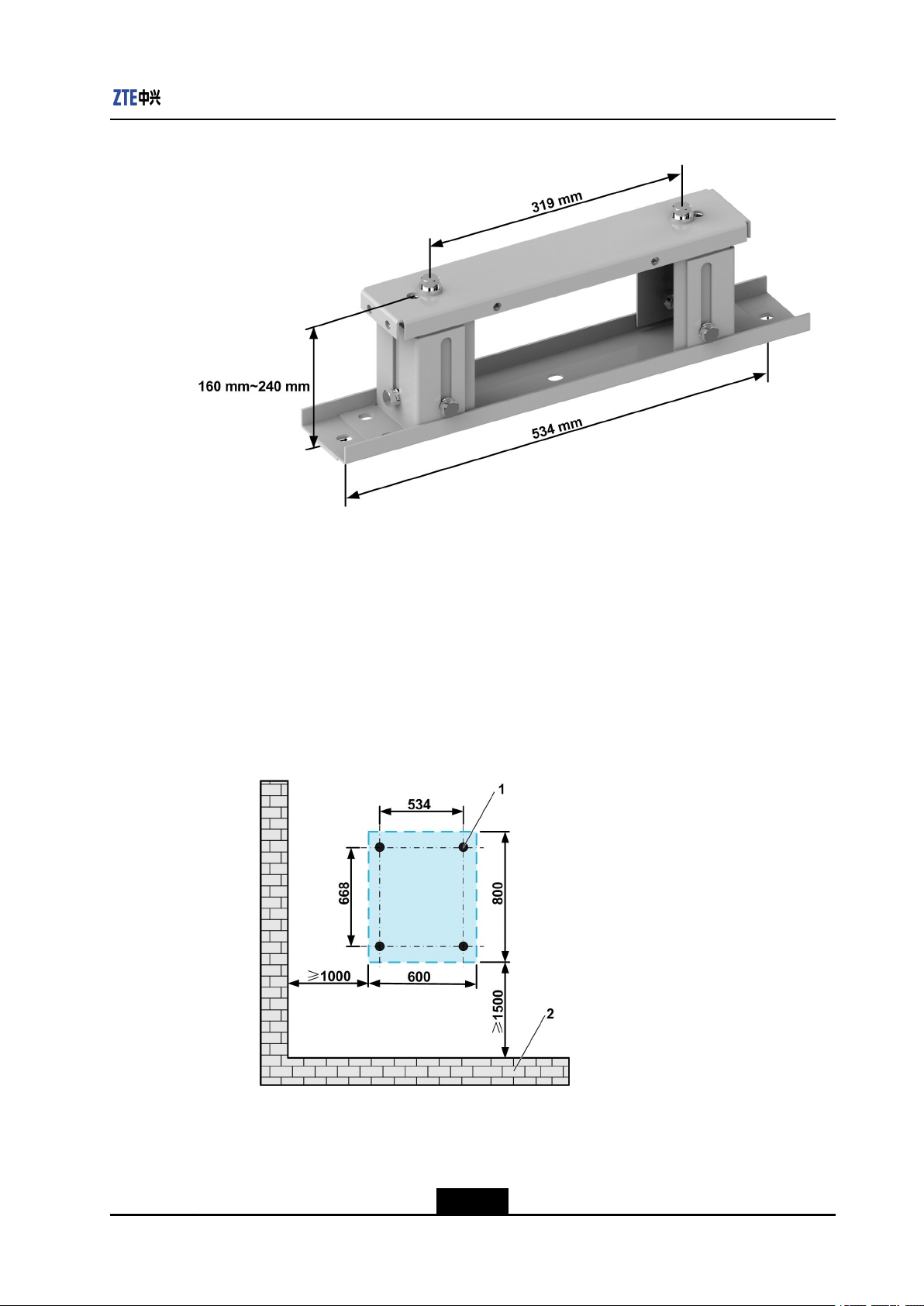
Figure5-4AdjustableBaseofTypeA
Chapter5CabinetInstallation
Steps
Positioningtheadjustablebase
1.Removethestaticconductiveooranditsbracesattheplacewherethecabinetisto
beinstalled.
2.Drawlinesbyusingmeasurementtoolsandline-drawingtoolstomarktheinstallation
holesfortheadjustablebase.
lForthepositionofholesforinstallingasinglecabinet,seeFigure5-5.
Figure5-5MarkingHolesforInstallingaSingleCabinet(Unit:mm)
1.Installationhole2.Wall
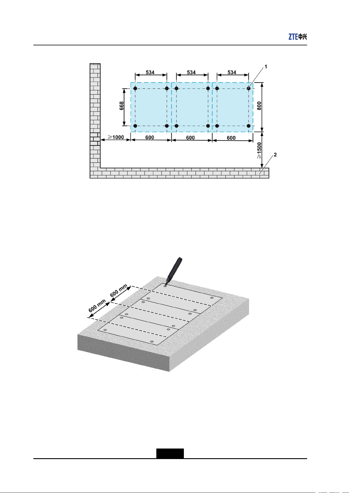
lFortheinstallationholesofsocketboltsfortheadjustablebasestoinstallmultiple
cabinets,seeFigure5-6.
5-5
SJ-20141121113158-006|2014-12-20(R1.0)ZTEProprietaryandCondential
NetNumen™U31R06HardwareInstallationGuide
Figure5-6MarkingHolesforInstallingMultipleCabinets(Unit:mm)
1.Installationhole2.Wall
3.Putthedrillingtemplateonthemarkedpositions.Iftheholesonthetemplatematch
theinstallationholesmarkedinstep2.,markallinstallationholesforthebasebyusing
amarkerpen,seeFigure5-7.
Iftheholesdonotmatch,adjusttheholessothatthelinesdrawninstep2.arecorrect.
Figure5-7MarkingInstallationHolesUsingtheDrillingTemplate
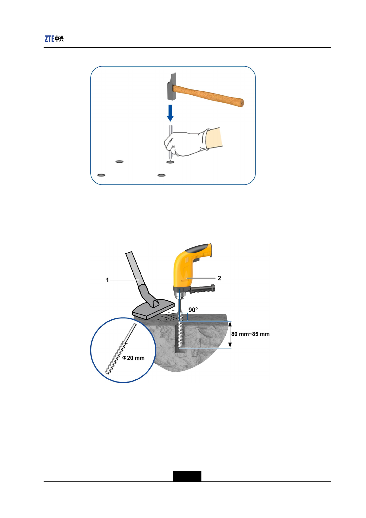
4.Inaccordancewiththepositionofthesocketboltmarkedontheoor,makean
indentationattheholelocationrstbyusingapunchtohelplocatethedrillbit,see
Figure5-8.
5-6
SJ-20141121113158-006|2014-12-20(R1.0)ZTEProprietaryandCondential
Chapter5CabinetInstallation
Figure5-8DrillingIndentations
5.Adjustthescalethatdeterminesthedepthofthehole,andthenpressthepercussion
drilldownwardverticallytodrillholes.Usethevacuumcleanertoremovethedust
insideandoutsidetheholes,seeFigure5-9.
Figure5-9DrillingaHole
1.Vacuumcleaner2.Percussiondrill
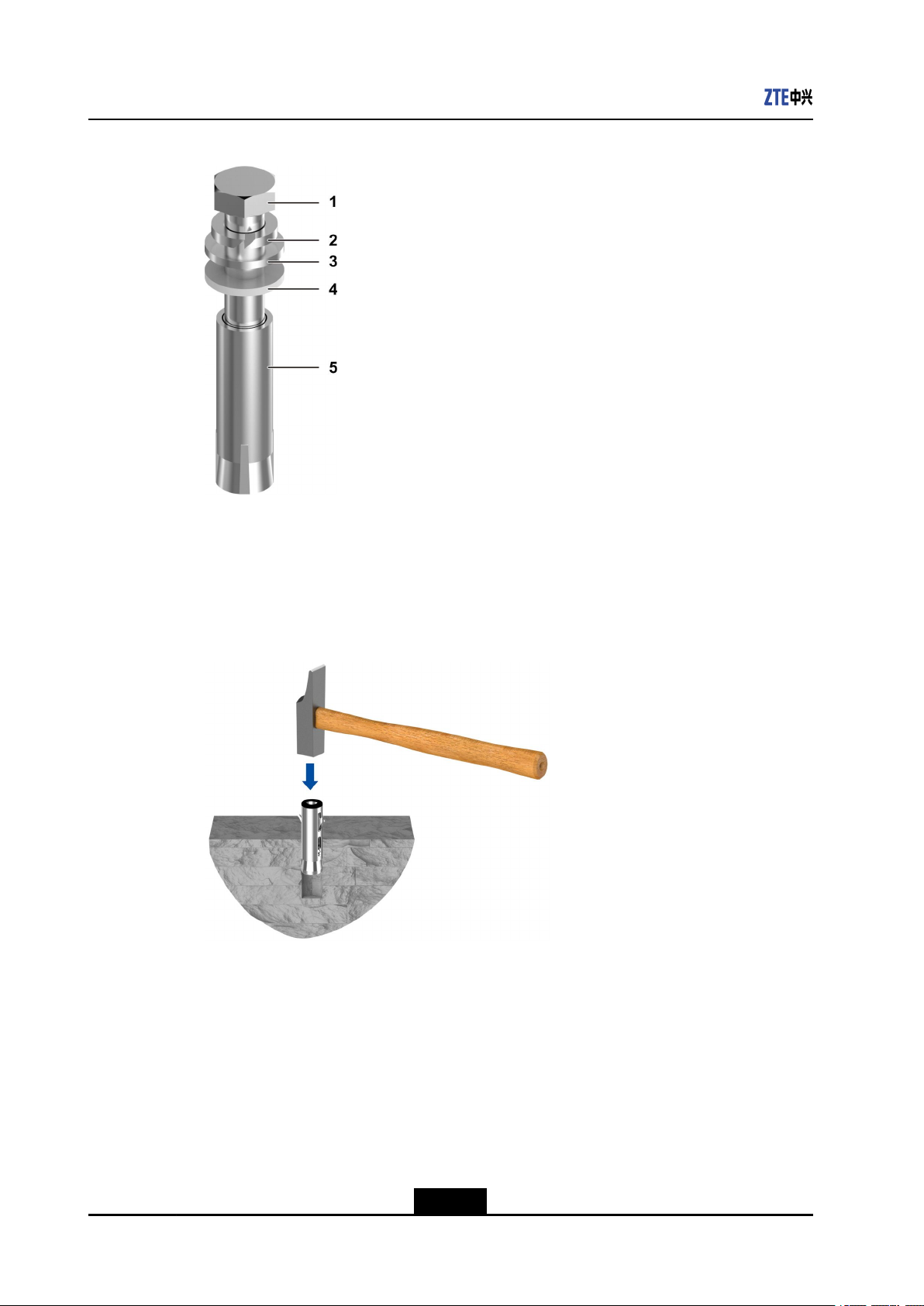
6.Removethebolt,springwasher,insulatingwasher,andgasketoftheAN01socket
bolt.
FortheoverviewofAN01socketbolt,seeFigure5-10.
5-7
SJ-20141121113158-006|2014-12-20(R1.0)ZTEProprietaryandCondential
NetNumen™U31R06HardwareInstallationGuide
Figure5-10AN01SocketBolt
1.M12×90bolt
2.Springwasher
3.Gasket
4.Insulatingwasher
5.Expansiontube
7.Installthesocketboltverticallyintothehole.Hammerthesocketboltbyusingthe
clawhammeruntiltheexpansiontubeenterstheholecompletely,seeFigure5-1 1.
Figure5-11HammeringaSocketBolt
Mountingtheadjustablebase
8.Measuretheheightbetweentheconcreteoorandthesurfaceofthestaticconductive
oorbyusingatapemeasure.
9.Adjusttheadjustablebasetomakethescaleindicationonthebaseequaltotheheight
ofthestaticconductiveoor,seeFigure5-12.
Thetighteningtorqueofaheight-lockingboltshouldreach40N·m.
5-8
SJ-20141121113158-006|2014-12-20(R1.0)ZTEProprietaryandCondential
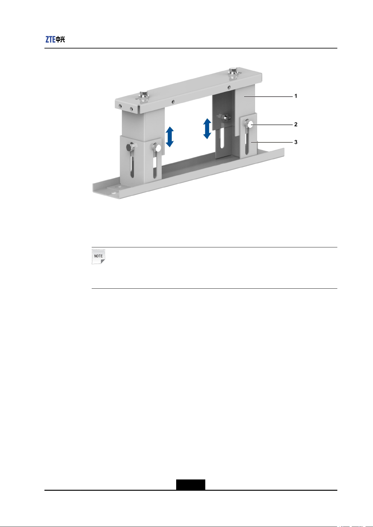
Figure5-12AdjustingtheHeightofanAdjustableBase
Chapter5CabinetInstallation
1.Movablebracket2.Height-locking
M12×25bolt
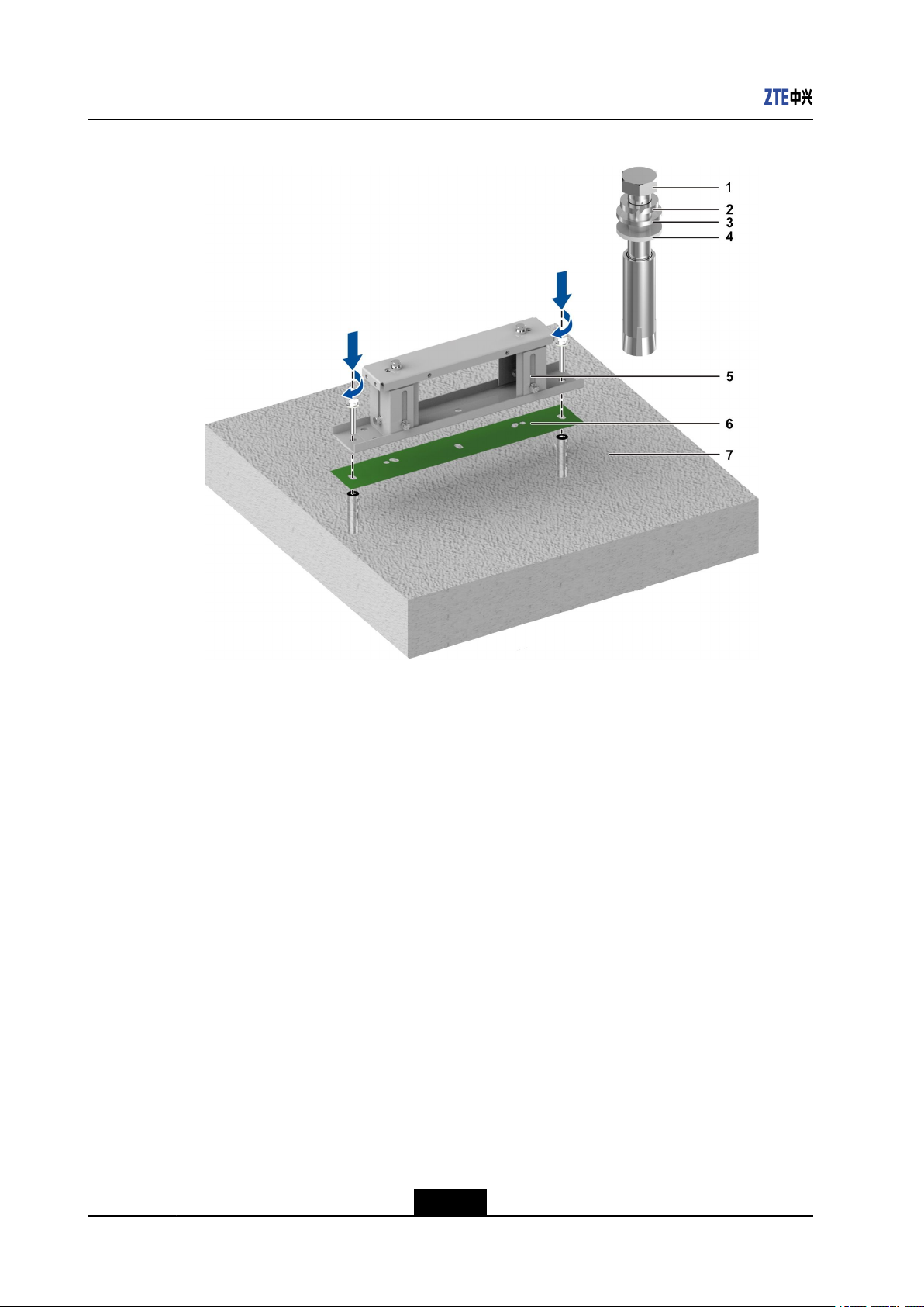
10.Securetheadjustablebase,seeFigure5-13.
Note:
Thetighteningtorqueofaboltshouldreach75N·m.
3.Fixedbracket
5-9
SJ-20141121113158-006|2014-12-20(R1.0)ZTEProprietaryandCondential
NetNumen™U31R06HardwareInstallationGuide
Figure5-13SecuringanAdjustableBase
1.M12×90bolt
2.Springwasher
3.Gasket
4.Insulatingwasher
5.Adjustablebase
6.Insulatinggasket
7.Concretefloor
11.RemoveM12×35boltsfromtheadjustablebasebyusinganadjustablewrench.
Removespringwashersandgasketsfromthebolts,seeFigure5-14.
5-10
SJ-20141121113158-006|2014-12-20(R1.0)ZTEProprietaryandCondential
 Loading...