

Zte NCN 52 Quick Start Manual
NCN 52 Series HD Semi-dome IP Camera Quick Start Guide
Add: 4/F,W1-A,Bldg,Gaoxin S.1th Ave.,Hi-Tech Park,Nanshan District,Shenzhen,PRC ZIP Code:518057 Website: http://www.ztenv.com.cn E-mail:0049001000@zte.com.cn/ wang.guofu@zte.com.cn
Tel:(86) 755 26525680-2503 / (86) 755-400-8866755 FAX:(86) 755 26520574 Serial No.: SJ-20120528174826-001
1
The quick guide is for quick installing this produc t. For details, please refer to the camera’s User Manual.
Installation Guide
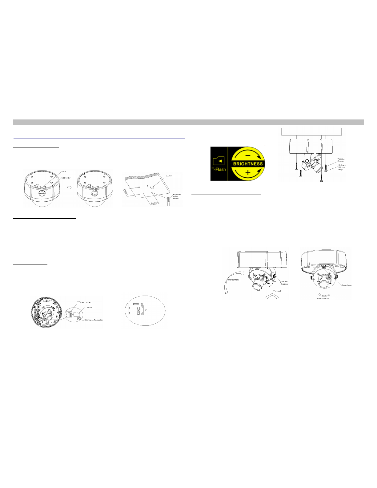
Lead cables through ceiling or side of the semi-dome camera according to the installation condition. If from side
of camera, unscrew the screw on the side and remove the thin wall of the line outlet with pliers and debur it, as
shwon in
1. Outgoing Line Mode
Figure 1.
Figure 1 Outgoing from Side Figure 2 Install Expansion Screw Sleeve
Drill four Φ6 holes (center distance of holes are 90*86.8mm) with an impact drill on the mounting p late. Press four
Φ6 screw sleeves into the holes (supplied with accessories); If lead cables through ceiling, drill an outlet first.
The location of outlet should be determined appropriately based on the bottom case of the semi-dome camera,
as shown in Figure 2.
2 Install expansion screw sleeve
Connect cables, including video, alarm, power, audio, and network cables, by tags as per Figure 16 and Table 1.
3 Connect Cables
To install TF card, please perform the following steps: 1) Open the bottom cover; 2) Place TF card on PCB
flatly; 3) Insert TF card into the TF card socket as in the direction of arrow , as shown in
4 Install TF Card
Figure 3.
To pull out TF card, please perform the following steps: 1) Push the TF card in the direction of the arrow,
then release; 2) Take the TF card out at about 1cm from TF card socket, as shown in Figure 4.
Figure 3 Install TF Card and Adjust Brightness Figure 4 Pull out TF Card
For HD manual zoom color semi-dome IP camera, it is required to adjust brightness. To do so, please perform
the following steps: Adjust brightness regulator is as shown in
5 Adjust Brightness
Figure 3. Adjust the regulator to proper position,
clockwise to increase the brightness, counterc lockwise to decrease, as shown in Figure 5.
Figure 5 TF Card Installation and Brightness Adjustment Figure 6 Bottom Case Installation
Take the four O-shape silicone rings (Spec: D8*2.5) and the four tapping screws (Spec: BA4*25) out from the
accessory bag, put the four silicone rings onto the four tapping screws, and then pass them through the four
holes on the bottom case and aim them at the four expansion screw sleeves on the ceiling, fasten them with
cross screw driver, as shown in Figure.
6 Lock the bottom case onto ceiling
(1) Aim the lens at the target direction, r otate it in horizontal (0-3600) and vertical (±60 0) direction s respectively to
adjust, and then tighten the thumb screws at both s i des of the U-shape bracket, as shown in
7 Adjust HD Semi-dome IP Camera from Three-axis
Figure 7.
Figure 7 Three-axis Adjustment Figure 8 Adjust Optical Axis of Lens
(2) Confirm the image formed is exactly consistent with actual observed scene, if any inversion or deflection,
loosen the thumb screws and rotate the camera to adjust the opt ical axis w ithin 360
0
till the image is totally fit
with the actual situation, then tighten the two screw s, as shown in Figure 8.
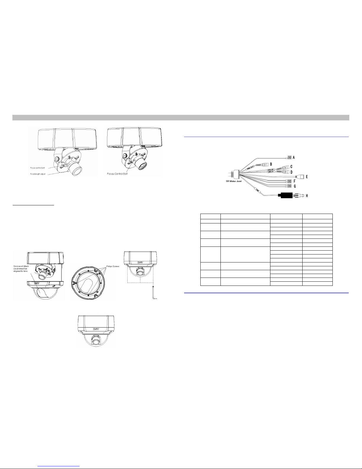
For manual zoom lens, the focal length of lens is required to be adjusted. To adjust it, perform the following:
Loosen the focus control bolt, then adjust the focal length to an appropriate position by rotating the focal length
adjusting bolt toward “T” or “W”, tighten the focus control bolt, then loosen the focal length adjust bolt and rotate
the focusing ring clock/counterclock-wise till the optimum image effect is obtained, as shown in
8 Adjust Lens
Figure 9.
NCN 52 Series HD Semi-dome IP Camera Quick Start Guide
Add: 4/F,W1-A,Bldg,Gaoxin S.1th Ave.,Hi-Tech Park,Nanshan District,Shenzhen,PRC ZIP Code:518057 Website: http://www.ztenv.com.cn E-mail:0049001000@zte.com.cn/ wang.guofu@zte.com.cn
Tel:(86) 755 26525680-2503 / (86) 755-400-8866755 FAX:(86) 755 26520574 Serial No.: SJ-20120528174826-001
2
Figure 9 Adjust Focal Length of Manual Zoom Lens Figure 10 Focus Control of Fixed-Focal Lens
For fixed-focal lens, just performing focusing adjustment is enough. To do it, perform the following: loosen the
focus control bolt and rotate the focusing ring clock/counterclockwise till the optimum image effect is obtained
and tighten the bolt, as shown in Figure 10.
Try the lower cover onto the bottom case; confirm that the black cover aligning to the lens exactly, as shown in
9 Install Bottom Case
Figure 11. If not, loosen the four Philips screws on the lower cover (do not remov e them) with a cross screwdriver,
as shown in Figure 12. Then turn the transparent cover with hand to make the black cover aligning to the lens,
then tighten the four Philips screws. Use the Torx T20 screwdriver which is supplied in the accessory bag to
mount the lower cover onto the bottom case, tighten the thr ee hex capt ive screws, as shown in Figure 13. Finally,
tear off the protective film from the transparent cover. Now the installation of camera is completed, as shown in
Figure 14.
Figure 11 Black Cover Aligning to Lens Figure 12 Rotate Black Cover Figure 13 Install Lower Cover
Figure 14 Camera Installed
The wiring diagram of NCN 52 HD Semi-dome IP camera cables, including ground, power, audio/ vide o, net work,
and alarm, etc. is as shown in
Wiring Instruction
Figure 15. Table 1 lists the detailed connection of these cables.
Figure 15 Wiring Diagram
Table 1 Connection Description
Mark
Name (Symbol)
Pin
Color of core wire
A
Protective (GNDP)
GNDP
Red-White
B
Power (X24)
(POWER DC12V)
12V_IN
Red
GND
Black
C
Audio output (X21)
(AUDIO_OUT)
AO
Purple
GND
Black and white
D
Audio Input (X21)
(AUDIO_IN)
AI
Yellow
GND
Pink
E
Network interface (X23)
TX+(1) TX-(2)
RX+(3) RX-(6)
TX+
Orange-white
TX-
Orange
RX+
Green
RX-
Green-white
F
Alarm Input (X21)
GND
Brown-white
DI
Brown
G
Alarm output (X21)
DO
Gray
COM
Blue-white
H
Video output (X21)
(VIDEO)
GND
Black
VO
White
IP Address:192.168.1.2
Initial Setup
User Name: admin
Password: 12345
 Loading...