

Page 1

ZXC10-BTSB I2(V1.0)
cdma2000 System
Base Transceiver St ation
Installation Manual
ZTE CORPORATION
Page 2

ZXC10-BTSB I2(V1.0) cdma2000 System Base Transceiver Station
Installation Manual
Manual Version 20050401-R1.0
Product Version V1.0
Copyright © 2005 ZTE Corporation
All rights reserved.
No part of this documentation may be excerpted, reproduced, translated, annotated or
duplicated, in any form or by any means without the prior written permission of ZTE
Corporation.
* * * *
ZTE CORPORATION
ZTE Plaza, Keji Road South, Hi-Tech Industrial Park, Nanshan District, Shenzhen, P.R.China
Website: http://www.zte.com.cn
Postcode: 518057
Customer Support Center: (+86755) 26771900 800-9830-9830
Fax: (+86755) 26770801
Email: support@zte.com.cn
* * * *
Page 3
FAX: 0086-755-26770160
Suggestions and Feedback
To improve the quality of ZTE product documentation and offer better services to our customers, we hope
you can give us your suggestions and comments on our documentation and fax this form to
+86-755-26770160; or mail to “Marketing center 3rd floor ZTE Plaza, Keji Road South, Hi-Tech Industrial
Park, Nanshan District, Shenzhen, P. R. China”. Our postcode is 518057.
Document name ZXC10-BTSB I2(V1.0) cdma2000 System Base Transceiver Station Installation Manual
Product version V1.0 Document version 20050401-R1.0
Equipment installation time
Your information
Name Company
Postcode Company address
Telephone E-mail
Presentation: How is information presented? (Introductions, procedures, illustrations, others)
F Good F Fair F Average F Poor F Bad
Your evaluation
of this
documentation
Your su g g e s t i o n s
for improvement
of this
documentation
Your other
suggestions on
ZTE product
documentation
Accessibility: Can you find the information you want? (Table of contents, Index, headings, numbering,
others)
F Good F Fair F Average F Poor F Bad
Intelligibility: Can you understand it when you find it? (Language, vocabulary, readability, others)
F Good F Fair F Average F Poor F Bad
Presentation:
Accessibility:
Intelligibility:
Page 4

Page 5

FAX: 0086-755-26770160
Preface
About This Manual
This manual introduces the hardware installation flow and method of the ZXC10
BTSB I2.
It is one of the manuals of the CDMA cellular mobile communication system of ZTE.
This manual is intended to provide basic installation operation guide to the engineering
staff that install the ZXC10 BTSB I2 of ZTE. Operation and maintenance staff of the
equipment can also use it as reference.
Standardized hardware installation is the basis for the normal and stable operation of
the BS and is thus important in the project engineering. To guide the hardware
installation of ZXC10 BTSB I2, this manual is arranged in the order of engineering
installation. This manual first briefs the equipment composition, which enables the
engineering staff to have an overall understanding of the ZXC10 BTSB of ZTE. Then it
details the installation flow of the equipment and the installation check.
How to Use This Manual
This manual comprises 15 chapters:
Chapter 1 Overview of BTS Installation briefs the equipment installation and
commissioning flow, the hardware installation flow and the hardware installation
precautions for the BTS system.
Chapter 2 Installation Preparation
installation, including installation environment check, and preparation for tools,
instruments and technical documentation.
Chapter 3 Unpacking Inspection describes unpacking, acceptance and handover of
the goods.
Chapter 4 Installing the Cabinets describes the installation of the BTSB cabinet, and
the layout, connection and fixing of multiple cabinets.
Chapter 5 Power System Installation
BTSB power system.
introduces the preparations prior to the BTSB
describes the installation procedure of the
-i-
Page 6

Chapter 6 Installing the Grounding System describes the installation procedure of
the BTSB grounding system.
Chapter 7 Installing the Cabinet Internal Cables introduces the types of BTSB
cabinet internal cables, and describes the installation procedure of them.
Chapter 8 Installing the Trunk Cables describes the installation procedure of the
BTSB trunk cables, and explains how to prepare the E1 cables and how to convert the
75 Ω trunk cables into the 120 Ω trunk cables.
Chapter 9 Installing the Monitoring System introduces the composition of the
monitoring system and describes its installation procedure.
Chapter 10 Installing the Main Antenna Feeder System describes the installation
preparation, the installation flow and the specific installation procedure of the main
antenna feeder system, and explains how to check and test the antenna feeder and how
to conduct waterproof treatment on the connector.
Conventions
Chapter 11 Installing the GPS Antenna Feeder System
preparation, the installation flow and the specific installation procedure of the GPS
antenna feeder system.
Chapter 12 Installing the Board describes the types and functions of boards used in
the BTSB system, and how to install and replace them.
Chapter 13 Hardware Installation Check describes the hardware installation check
requirements of the BTSB system.
Chapter 14 Power-on/Power-off
the detailed power-on and power-off operation procedures.
Appendix A gives an abbreviation form.
Describing notational conventions, keyboard operation convention, mouse operation
convention and four safety signs.
1. Notational conventions
describes the check prior to the BTSB power-on, and
describes the installation
Angular brackets "<and>" identify names of keys and buttons, and the
information typed by an operator from a terminal. Square brackets "[and]"
indicate a man-machine interface, menu item, data list, or field name. The
Page 7
symbol "-->" separates a multi-level menu, e.g., [File --> New --> Folder]
indicates the [Folder] menu item under the [New] submenu of the menu [File].
2. Keyboard operation conventions
Format Description
Character within angular
brackets
<key 1+key 2>
<key 1, key 2>
Indicating a key or button name, e.g., <Enter>, <Tab>,
<Backspace>, and <a>
Indicating to hold several keys down at the same time. For
example, <Ctrl+Alt+A> indicates to hold down “Ctrl”, “Alt”
and “A” three keys
Press Key 1 first. Then release Key 1 and press Key 2. For
example, <Alt, F> indicates to press and release <Alt> key, and
then press <F> key
3. Mouse operation conventions
Format Description
Click Refers to clicking the primary mouse button (usually the left
mouse button) once
Double-click Refers to quickly clicking the primary mouse button (usually the
left mouse button) twice
Right-click Refers to clicking the secondary mouse button (usually the right
mouse button) once
Drag Refers to pressing and holding a mouse button and move the
mouse
4. Signs
Four eye-catching signs are used in this manual to emphasize important and
critical information.
Note,
Caution, Warning, and Danger:
Used to
indicate the precautions during the operation.
Statement: The actual product may differ from what is described in this
manual due to frequent update of ZTE products and fast development of
technologies. Please contact the local ZTE office for the latest updating
information of the product.
Page 8

Page 9

FCC & IC STATEMENT
Before using this CDMA ZXC10 BTSB I219 and BTSB I208, read this important RF energy
awareness and control information and operational instructions to ensure compliance with the
FCC and IC RF exposure guidelines.
NOTICE: Working with the equipment while in operation, may expose the technician to RF
electromagnetic fields that exceed FCC rules for human exposure. Visit the FCC website at
www.fcc.gov/oet/rfsafety
Changes or modifications to this unit not expressly approved by the party responsible for
compliance will void the user’s authority to operate the equipment. Any change to the equipment
will void FCC and IC grant.
This equipment has been tested and found to comply with the limits for a Class A digital device,
pursuant to the FCC and IC Rules. This equipment generates, uses and can radiate radio frequency
energy and, if not installed and used in accordance with the instructions, may cause harmful
interference to radio communications. However, there is no guarantee that interference will not
occur in a particular installation.
A PNALE Antenna with a maximum gain of 17dBi is authorized for use with this unit. Outside
antennas must be positioned to observe minimum separation of 2.6M (8.528 feet.) for 800MHz
unit and 1.6M (5.248 feet.) for 1900MHz unit from all users and bystanders. For the protection of
personnel working in the vicinity of outside (uplink) antennas, the following guidelines for
minimum distances between the human body and the antenna must be observed.
The installation of an antenna must be such that, under normal conditions, all personnel cannot
come within 2.6M (8.528 feet.)for 800MHz unit and 1.6M (5.248 feet.) for 1900MHz unit from
the outside antenna. Exceeding this minimum separation will ensure that the worker or bystander
does not receive RF-exposure beyond the Maximum Permissible Exposure according to section
1.1310 i.e. limits for Controlled Exposure.
to learn more about the effects of exposure to RF electromagnetic fields.
Page 10

Page 11

FAX: 0086-755-26770160
Contents
1 Overview of BTS Installation...................... ... .. ... .. ................................... ... .. .............................................i
1.1 Overview........................................................................................................................................1-1
1.2 Hardware Installation Flow............................................................................................................ 1-4
1.3 Precautions ..................................................................................................................................... 1-6
2 Installation Preparation..........................................................................................................................2-1
2.1 Installation Environment Inspection .............................................................................................. 2-1
2.1.1 Inspection of the Equipment Room Building...................................................................... 2-1
2.1.2 Inspection of the Indoor Environment ................................................................................2-2
2.1.3 Inspection of Power Supply ................................................................................................2-3
2.1.4 Electromagnetic Radiation Protection Requirements..........................................................2-4
2.1.5 Grounding Inspection .......................................................................................................... 2-4
2.1.6 Inspection of the Installation Environment for the Outdoor Antenna Feeder System.........2-5
2.1.7 Safety Inspection ................................................................................................................. 2-6
2.1.8 Inspection of Corollary Equipment ..................................................................................... 2-6
2.2 Preparation of Tools and Instruments............................................................................................. 2-7
2.3 Preparation of Technical Documents .............................................................................................2-8
3 Unpacking Inspection.............................................................................................................................3-1
3.1 Checking the Goods against the Packing List ................................................................................3-1
3.2 Unpacking the Wooden Box........................................................................................................... 3-2
3.2.1 Wooden Box Structure ........................................................................................................ 3-2
3.2.2 Unpacking ...........................................................................................................................3-2
3.2.3 Inspecting the Rack Outside View ...................................................................................... 3-3
3.3 Unpacking the Carton .................................................................................................................... 3-3
-i-
Page 12

3.3.1 Carton ................................................................................................................................. 3-3
3.3.2 Unpacking........................................................................................................................... 3-4
3.3.3 Inspecting the Boards ......................................................................................................... 3-4
3.4 Goods Acceptance and Handover.................................................................................................. 3-4
4 Installing the Cabinets............................................................................................................................ 4-1
4.1 External Structure of the BTS Cabinet .......................................................................................... 4-1
4.2 Cabinet Layout .............................................................................................................................. 4-2
4.3 Installing a Single BTS Cabinet..................................................................................................... 4-3
4.3.1 Installation Flow of a Single Cabinet.................................................................................. 4-3
4.3.2 Installation Procedure of a Single Cabinet.......................................................................... 4-4
4.4 Connecting and Fixing Multiple Cabinets .....................................................................................4-8
4.5 Cabinet Installation Requirements............................................................................................... 4-10
5 Power Supply System Installation......................................................................................................... 5-1
5.1 Introduction to Power Cables ........................................................................................................ 5-1
5.2 Installation Flow of Power Cables................................................................................................. 5-2
5.3 Cable Installation Procedure.......................................................................................................... 5-2
6 Installing the Grounding System........................................................................................................... 6-1
6.1 Overview of the BTS Grounding System ...................................................................................... 6-1
6.2 Installing the BTS Grounding System ........................................................................................... 6-2
6.2.1 Installing the Outdoor Grounding Copper Bar ................................................................... 6-2
6.2.2 Installing the Feeder Grounding Clip ................................................................................. 6-3
6.2.3 Installing the Indoor Lightning Arrester ............................................................................. 6-6
7 Installing the Cabinet Internal Cables . .. ... .. ... .. ... ... .. ... .. ... .. ... ................................... ... .. ... .. ... .. .............. 7-1
7.1 Overview of the Internal Cable Installation................................................................................... 7-1
7.1.1 Configuration Types of BTS............................................................................................... 7-1
7.1.2 Precautions for Installing the RF Cables on the Front Panel .............................................. 7-1
Page 13

7.2 Installing the Cables for the Single-carrier BTS and the Two-Carrier BTS ................................... 7-3
7.2.1 Installing the RF Cables for a Single-carrier Single-sector BTS......................................... 7-3
7.2.2 Installing the RF Cables for a Single-carrier Two-sector BTS............................................ 7-6
7.2.3 Installing the RF Cables for a Single-carrier Three-sector BTS ......................................... 7-9
7.2.4 Installing the RF Cables for a Two-carrier Three-sector BTS........................................... 7-14
7.2.5 Connecting the Backplane Signal Cables for the Rack of a Single-carrier or Two-carrier
BTS ............................................................................................................................................ 7-17
7.3 Installing the Cables for the BTS of Three Carriers and Above................................................... 7-17
7.3.1 Installing the RF Cables for a Three-carrier Three-sector BTS ........................................ 7-18
7.3.2 Installing the RF Cables for a Four-carrier Three-sector BTS .......................................... 7-23
7.3.3 Connecting the Jumper Cables Between the Basic Cabinet and the Extended Cabinet.... 7-28
7.3.4 Connecting the Backplane Signal Cables of the BTS Rack .............................................. 7-29
7.4 T1 Cabke ......................................................................................................................................7-31
7.4.1 Functions ...........................................................................................................................7-31
7.4.2 Connection Position of Two Ends, Wiring and Signal Flow Direction of Cable ..............7-31
7.4.3 Function ............................................................................................................................ 7-32
7.4.4 Connection Positions of Both Ends, Cabling and Signal Flow Direction of Cables.........7-32
8 Installing the Trunk Cables....................................................................................................................8-1
8.1 Installing the Trunk Cables ............................................................................................................ 8-1
8.2 Preparing the T1 cables ..................................................................................................................8-1
9 Installing the Monitoring System ..........................................................................................................9-5
9.1 Composition of the Monitoring System ......................................................................................... 9-5
9.2 Installing the Monitoring System ................................................................................................... 9-5
9.2.1 Installing the Indoor Smog Sensor ...................................................................................... 9-5
9.2.2 Installing the Indoor Temperature/Humidity Sensor...........................................................9-6
10 Installing the Main Antenna Feeder System.....................................................................................10-1
10.1 Installation Preparation for the Antenna Feeder System ............................................................ 10-1
Page 14

10.1.1 Preparations for Installation Staff ................................................................................... 10-2
10.1.2 Installation Environment Inspection ............................................................................... 10-2
10.1.3 Safety Measures Inspection ............................................................................................ 10-3
10.1.4 Preparation of Installation Tools..................................................................................... 10-3
10.2 Structure of the Antenna Feeder System.................................................................................... 10-4
10.3 Installation Content and Flow.................................................................................................... 10-5
10.3.1 Technical Parameters for Antenna Installation ............................................................... 10-6
10.3.2 Antenna Installation Flow............................................................................................... 10-6
10.4 Installing the Antenna Parts ....................................................................................................... 10-7
10.4.1 Determining the Antenna Installation Position ............................................................... 10-7
10.4.2 Handling and Hoisting the Antenna................................................................................ 10-8
10.4.3 Installing and Adjusting the Directional Antenna........................................................... 10-9
10.4.4 Installing and Adjusting the Omni Antenna.................................................................. 10-12
10.4.5 Connecting and Sealing the Jumper and the Antenna................................................... 10-12
10.4.6 Installing the Feeder Window....................................................................................... 10-13
10.4.7 Installing the Feeders .................................................................................................... 10-14
10.4.8 Installing the Indoor Jumpers ....................................................................................... 10-25
10.5 Checking and Testing the Antenna Feeders ............................................................................. 10-25
10.6 Waterproof Treatment for the Connectors ............................................................................... 10-25
11 Installing the GPS Antenna Feeder System.......................................................................................11-1
11.1 Installation Preparation for the Antenna Feeder System............................................................ 11-1
11.2 Structure of the Antenna Feeder System .................................................................................... 11-2
11.3 Installation Flow ........................................................................................................................ 11-2
11.4 Installing the Parts ..................................................................................................................... 11-3
11.4.1 Preparing the GPS Coaxial Cable Connectors ................................................................ 11-3
11.4.2 Installing the GPS Lightning Arrester............................................................................. 11-4
12 Installing the Boards .......................................................................................................................... 12-1
Page 15

12.1 Board Types and Functions of BTS ...........................................................................................12-1
12.2 Introduction to Main BTS Modules ...........................................................................................12-4
12.2.1 RFE Module .................................................................................................................... 12-4
12.2.2 HPA .................................................................................................................................12-6
12.2.3 TRX................................................................................................................................. 12-8
12.3 Installing and Replacing Boards .............................................................................................. 12-10
12.4 Introduction to BDS Plug-in Shelves .......................................................................................12-13
13 Hardware Installation Check.............................................................................................................13-1
13.1 Cabinet Check ............................................................................................................................ 13-1
13.2 Check of cabling rack.................................................................................................................13-2
13.3 Laying, Binding and Identification of Cables ............................................................................13-2
13.4 Installation Check in terms of power cables and ground wires..................................................13-3
13.5 Check of T1 Cable Installation................................................................................................... 13-5
13.6 Sensor Installation Check...........................................................................................................13-5
13.7 Installation Check of Connections inside a Cabinet...................................................................13-6
13.8 Installation Check of Indoor 1/2" Jumpers.................................................................................13-6
13.9 Installation and Check of Lightning Arrester .............................................................................13-7
13.10 Installation and Check of Lightning Arrester Rack.................................................................. 13-7
13.11 Installation and Check of Main Feeder and GPS Feeder..........................................................13-7
13.12 Installation and Check of Feeder Windows and Waterproof Bend of the Main Feeder ...........13-9
13.13 Installation and Check of Three-way Feeder Card.................................................................13-10
13.14 Installation and Check of Outdoor 1/2" Jumpers ................................................................... 13-10
13.15 Installation and Check of an Antenna .................................................................................... 13-11
13.16 Check of the Standing Wave Ratio of a Feeder ...................................................................... 13-13
13.17 Check of Indoor/Outdoor Environment ................................................................................. 13-13
14 Power-on/Power-off.............................................. ... .. ... .. ... .. ... .. ... ................................... .....................14-1
14.1 Check before Power-on.............................................................................................................. 14-1
Page 16

14.1.1 Check of External Connections of the rack .................................................................... 14-1
14.1.2 Check of Rack Inside...................................................................................................... 14-1
14.2 Power-on Procedures ................................................................................................................. 14-2
14.3 Power-off Procedures ................................................................................................................ 14-3
Appendix A Abbr eviations....................................................................................................................... A-1
Page 17

FAX: 0086-755-26770160
List of Figures
Fig. 1.1-1 Overall Structure of the BTSB I2 Rack with the BDS Plug-in Shelf ............................... 1-2
Fig. 1.1-2 Schematic Diagram of the BTS Equipment Installation................................................... 1-3
Fig. 1.2-1 Hardware Installation Flow ..............................................................................................1-5
Fig. 3.2-1 Structure of the Wooden Box............................................................................................3-2
Fig. 3.3-1 Packing Box of the Module ..............................................................................................3-4
Fig. 4.1-1 Outside View and Dimensions of the Rack ......................................................................4-2
Fig. 4.2-1 Layout of Equipment inside the ZXC10-BTSB I2 Equipment Room..............................4-3
Fig. 4.3-1 Assembly of the BTS Rack Base...................................................................................... 4-4
Fig. 4.3-2 Fixing the Base with the Rack ..........................................................................................4-5
Fig. 4.3-3 Installation Holes of the BTS Rack ..................................................................................4-6
Fig. 4.3-4 Fixing the Rack................................................................................................................. 4-7
Fig. 4.3-5 Installing the Rack Baffle Plates....................................................................................... 4-8
Fig. 4.4-1 Enlarged View of the Cable Hole Cover Plate.................................................................. 4-9
Fig. 4.4-2 Assembling the Connecting Bars on the Cabinet Top ...................................................... 4-9
Fig. 4.4-3 Effect Diagram of Two Cabinets Installed......................................................................4-10
Fig. 5.1-1 BDS Power Cable Installation on BTSB .......................................................................... 5-1
Fig. 5.2-1 Installation Flow of RFS Power ....................................................................................... 5-2
Fig. 5.3-1 RFS Power Cabling .......................................................................................................... 5-3
Fig. 5.3-2 BDS Power Cabling ......................................................................................................... 5-3
Fig. 5.3-3 Connection between Busbar and Backplane.....................................................................5-4
Fig. 5.3-4 Connecting Power Cable (1)............................................................................................. 5-5
Fig. 5.3-5 Connecting Power Cable (2)............................................................................................. 5-6
Fig. 6.1-1 Wiring for the BTS Ground..............................................................................................6-2
-i-
Page 18

Fig. 6.2-1 Profile of the Grounding Copper Bar............................................................................... 6-3
Fig. 6.2-2 Structure of the Grounding Clip....................................................................................... 6-4
Fig. 6.2-3 Wrapping the Grounding Wire of the Grounding Clip with Waterproof Tape................. 6-5
Fig. 6.2-4 Installing the Lightning Arrester Frame ........................................................................... 6-7
Fig. 7.1-1 Structure of the RF Cables on the Front Panel of the Rack.............................................. 7-2
Fig. 7.2-1 RF Cable Connection on the Front Panel of the Rack for the Single-carrier Single-sector
BTS...................................................................................................................................................... 7-4
Fig. 7.2-2 Front Panel Wiring for the Rack of the Single-carrier Single-sector BTS with the BDS
Plug-in Shelf ........................................................................................................................................ 7-5
Fig. 7.2-3 RF Cable Connection on the Front Panel of the Rack for the Single-carrier Two-sector
BTS...................................................................................................................................................... 7-7
Fig. 7.2-4 Front Panel Wiring for the Rack of the Single-carrier Two-sector BTS with the BDS
Plug-in Shelf ........................................................................................................................................ 7-8
Fig. 7.2-5 Circuitry on the Front Panel of the Rack for the Single-carrier Three-sector BTS........ 7-10
Fig. 7.2-6 Front Panel Wiring for the Rack of the Single-carrier Three-sector BTS ...................... 7-11
Fig. 7.2-7 Front Panel Wiring for the Rack of the Single-carrier Three-sector BTS with the
EBDS-HS Part of the EBDS Hybrid Shelf ........................................................................................ 7-12
Fig. 7.2-8 Circuitry on the Front Panel of the Rack for the Two-carrier Three-sector BTS ........... 7-14
Fig. 7.2-9 Front Panel Wiring for the Rack of the Two-carrier Three-sector BTS ......................... 7-15
Fig. 7.3-1 Circuitry on the Front Panel of the Rack for the Three-carrier Three-sector BTS......... 7-19
Fig. 7.3-2 Front Panel Wiring for the Rack of the Three-carrier Three-sector BTS ....................... 7-20
Fig. 7.3-3 Circuitry on the Front Panel of the Rack for the Four-carrier Three-sector BTS........... 7-24
Fig. 7.3-4 Front Panel Wiring for the Rack of the Four-carrier Three-sector BTS......................... 7-25
Fig. 7.3-5 Structure of the LINK Cable .......................................................................................... 7-30
Fig. 7.3-6 LINK Cable Structure .................................................................................................... 7-30
Fig. 7.4-1 100ΩT1 Cable Diagram................................................................................................. 7-31
Fig. 7.4-1 Terminals of the 100Ω Cable ......................................................................................... 7-33
Fig. 7.4-2 120 Ω Cable ................................................................................................................... 7-34
Page 19

Fig. 7.4-3 120 Ω T1 Conversion Cable ........................................................................................... 7-35
Fig. 7.4-4 BTS Rack-top Interface Board .......................................................................................7-35
Fig. 8.2-1 Assembly Drawing of the CC4Y-J32 Coaxial Cable Connector ......................................8-2
Fig. 8.2-2 Coaxial Connector of the DDF .........................................................................................8-3
Fig. 8.2-3 Assembly Drawing of the Coaxial Cable Connector of DDF........................................... 8-4
Fig. 9.2-1 Installing the Smog Sensor Base ......................................................................................9-6
Fig. 9.2-2 Installing the Temperature/Humidity Sensor.................................................................... 9-7
Fig. 10.2-1 Typical Structure of the Antenna Feeder System of Three-sector BTS ........................ 10-5
Fig. 10.3-1 Antenna Installation Flow ............................................................................................ 10-7
Fig. 10.4-1 Hoisting an Antenna ..................................................................................................... 10-9
Fig. 10.4-2 Installing the Kathrein Antenna .................................................................................. 10-11
Fig. 10.4-3 Adjusting the Pitch Angle of the Antenna .................................................................. 10-12
Fig. 10.4-4 Structure of the Feeder Window................................................................................. 10-14
Fig. 10.4-5 Structure of a BTS Feeder .......................................................................................... 10-15
Fig. 10.4-6 Cutting Tool for the 7/8" Feeder Connector ...............................................................10-16
Fig. 10.4-7 Cutting the Feeder with a Cutter.................................................................................10-17
Fig. 10.4-8 Checking the Cutting Length of the Feeder................................................................10-17
Fig. 10.4-9 Expand the External Conductor of the Feeder with a Tube Expander........................ 10-17
Fig. 10.4-10 Connecting the Front Part and the Back Part of the Feeder Connector .................... 10-18
Fig. 10.4-11 Fixing the Front Part and the Back Part of the Feeder Connector ............................ 10-18
Fig. 10.4-12 Hoisting the Feeder to the Tower..............................................................................10-21
Fig. 10.4-13 Three-feeder Clip......................................................................................................10-22
Fig. 10.4-14 Method 1 of Introducing Feeders into the Equipment Room ................................... 10-23
Fig. 10.4-15 Method 2 of Introducing Feeders into the Equipment Room ................................... 10-23
Fig. 10.6-1 Wrap the Waterproof Adhesive Tapes (1) ................................................................... 10-26
Fig. 10.6-2 Wrap the Waterproof Adhesive Tapes (2) ................................................................... 10-26
Fig. 10.6-3 Wrap the Waterproof Adhesive Tapes (3) ................................................................... 10-27
Page 20

Fig. 11.2-1 Structure of the GPS Antenna Feeder System.............................................................. 11-2
Fig. 11.4-1 Stripping the GPS Coaxial Cable ................................................................................. 11-3
Fig. 11.4-2 Welding the Pins of the GPS Connector....................................................................... 11-3
Fig. 11.4-3 Structure of the N-J7A Cable Assembly....................................................................... 11-4
Fig. 12.2-1 Panel of RFE Modules ................................................................................................. 12-5
Fig. 12.2-2 Structure of the HPA Front Panel ................................................................................. 12-7
Fig. 12.2-3 Structure of the TRX Front Panel................................................................................. 12-9
Fig. 12.3-1 Connectors on the Rear of the Boards and Modules .................................................. 12-11
Fig. 12.3-2 Front Panel of the Boards and Modules..................................................................... 12-12
Fig. 12.4-1 Slot Diagram of the BDS Plug-in Shelf ..................................................................... 12-13
Page 21

FAX: 0086-755-26770160
List of Tables
Table 2.1-1 DC Power Indexes for the Normal Operation of BTS ................................................... 2-3
Table 2.1-2 Power Consumption Indexes for the Normal Operation of BTS ................................... 2-4
Table 2.2-1 Tools Needed..................................................................................................................2-7
Table 2.2-2 Instruments Needed........................................................................................................2-8
Table 7.2-1 Front Panel Wiring of the Rack for the Single-carrier Single-sector BTS ..................... 7-6
Table 7.2-2 Front Panel Wiring of the Rack for the Single-carrier Two-sector BTS ........................ 7-9
Table 7.2-3 Front Panel Wiring of the Rack for the Single-carrier Three-sector BTS ....................7-13
Table 7.2-4 Front Panel Wiring of the Rack for the Two-carrier Three-sector BTS .......................7-16
Table 7.3-1 Wiring List of the Front Panel for the 1# Three-carrier BTS Cabinet.......................... 7-20
Table 7.3-2 Wiring List of the Front Panel for the 1# Four-carrier BTS Cabinet ........................... 7-26
Table 7.3-3 Wiring List of the Cables from 1# Multi-carrier BTS Cabinet to 2# Multi-carrier BTS
Cabinet ............................................................................................................................................... 7-28
Table 7.3-4 IDs of the LINK Directions..........................................................................................7-30
Table 7.4-1 100ΩT1 Cable Wiring and Signal Flow Direction.......................................................7-31
Table 7.4-1 Identifiers of the Location & Signal Flow Direction at Both Ends of the 100Ω Cable 7-33
Table 7.4-2 End B Braiding Pair Sequence of the 120 Ω T1 Conversion Cable ............................. 7-35
Table 9.2-1 Terminal Connection of the Smog Sensor Cable Connector.......................................... 9-6
Table 9.2-2 Terminal Connection of the Temperature/Humidity Sensor Cable Connector............... 9-7
Table 10.4-1 Model and Dimensions of the Feed Window........................................................... 10-14
Table 12.2-1 Description of the Interfaces on the RFE Panel .........................................................12-6
Table 12.2-2 Description of the Interfaces on the HPA Front Panel ............................................... 12-8
Table 12.2-3 Description of the TRX RF Interfaces ..................................................................... 12-10
-i-
Page 22

Page 23

FAX: 0086-755-26770160
1 Overview of BTS Installation
Summary
1.1 Overview
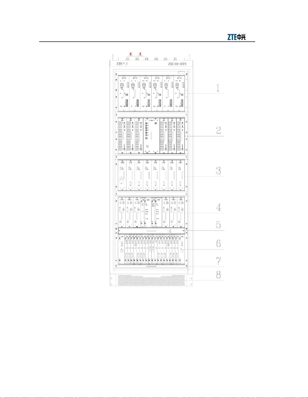
The integrated rack of ZXC10-BTSB comprises five layers each with an insertion box.
From top down, they are the RFE, HPA, power, TRX layer and BDS layers, as shown
in Fig. 1.1-1.
This part describes:
● Hardware installation flow of the BTS system;
● Installation precautions of the BTS system.
1-1
Page 24
ZXC10-BTS (V5.4) Installation Manual
1. RFE plug-in shelf base 2. HPA plug-in shelf 3. PSMD/PSMC plug-in shelf 4. TRX plug-in shelf
5. Fan plug-in shelf 6. BDS plug-in shelf 7. Dust filtering plug-in shelf 8. Base
Fig. 1.1-1 Overall Structure of the BTSB I2 Rack with the BDS Plug-in Shelf
The installation of the BTS system comprises the following parts:
1-2
Page 25
Chapter Error! Style not defined. Err
or! Style not defined.
1. The installation of the BTS cabinet, including the rack installation, the internal
cable installation, and the board installation and the DIP switch setting;
2. The installation of the power system to provide -48V operating power for the
system;
3. The installation of the grounding system to provide the protection ground for the
parts of the BTS equipment;
4. The installation of the antenna system, including the antenna positioning and
installation, jumper installation, feeder installation, and antenna feeder system
check and test;
5. The installation of the GPS system, including the installation of the GPS and the
feeder;
6. The installation of the trunk cable, including the connection of the cables and the
preparation of the connectors;
7. The installation of the monitoring system, including the installation of the
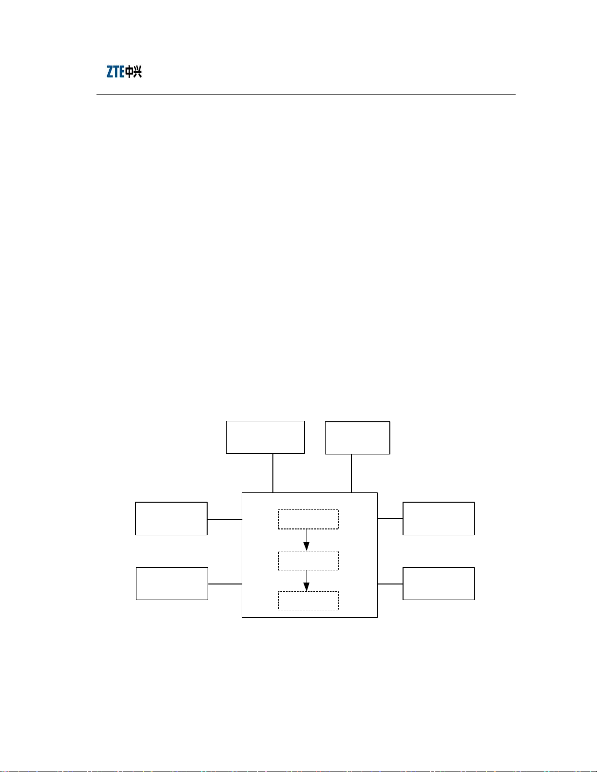
BTS system installation is shown in Fig. 1.1-2.
Install the power
supply system
Install the
grounding system
temperature/humidity sensor and the environment sensor.
Install the
GPS system
Install the BTS cabinet
Install the rack
Install the
internal cables
Ins tall the boards
Fig. 1.1-2 Schematic Diagram of the BTS Equipment Installation
Install the
antenna sy stem
Ins tall the
trunk cables
Ins tall the
alarm syst em
1-3
Page 26

ZXC10-BTS (V5.4) Installation Manual
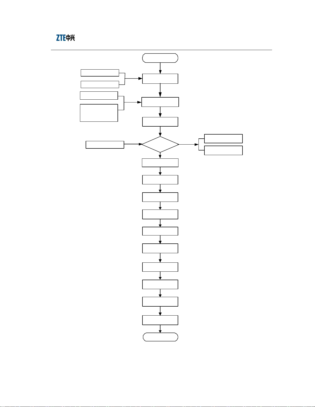
1.2 Hardware Installation Flow
The normal operation of the ZXC10-BTSB I2 equipment is closely related to the
quality of the installation engineering. The equipment must be installed in a systematic
and standardized way, which helps to remove the equipment stability problems caused
by improper installation and improve the reliability of the system.
This manual focuses on the step-by-step installation method and procedure of the BTS
and its parts. It provides details to enable users to finish the equipment installation.
The indoor installation of the ZXC10-BTS focuses on the rack installation, the indoor
cable preparation and routing. Please follow carefully the steps below:
1. Fix the rack base to the rack;
2. Position the rack;
3. Mark and drill holes for bolts;
4. Fix the cabinet;
5. Install the power cable on the rack top;
6. Install the temperature and humidity sensor on the set top;
7. Install the T1 cable;
8. Install boards and modules inside the rack;
9. Connect the RF cable at the rack front.
The detailed hardware installation flow of the BTS system is as shown in Fig. 1.2-1.
This manual describes the specific installation procedure by chapters according to this
flow.
1-4
Page 27
Chapter
Start
Error! Style not defined. Err
or! Style not defined.
Survey Report
Project design documents
Environment
Accept ance R eport
Cabling racks, power
supply system,
grounding system and
auxiliary facilities
Pack in g l is t
Project installation
preparati on
Ch eck t he engin eering
conditions
Unpacking In sp ecti on
Check the goods
for consistency
Yes
Instal l t he cab inets
Install the power
supply system
Install the
grounding system
Inst all th e
intern al cab les
No
Goods Error
Feed back Fo rm
Goods R epl acem ent
Application Form
Inst all th e
trunk cables
Install the
monitoring system
Instal l t he m ain
antenna feeder syst em
Install the
GPS system
Instal l t he b oards
Hardware
installation check
End
Fig. 1.2-1 Hardware Installation Flow
1-5
Page 28

ZXC10-BTS (V5.4) Installation Manual
1.3 Precautions
Precautions for the BTS hardware installation:
1. Take careful precautions for the safety of yourself and the equipment during the
installation;
2. Avoid hot plugging/unplugging during module installation;
3. Never install the antenna feeder system in case of lightning;
4. Check whether the lightning arrester is in proper contact before the
thunderstorm season every year. In case any lightning arrester is damaged,
replace it immediately;
5. Lock the cabinet door in time when the cabinet is installed.
1-6
Page 29

FAX: 0086-755-26770160
2 Installation Preparation
Summary
This part describes:
● Environment check prior to the BTS installation;
● Tool and instrument preparation prior to the BTS
installation;
● Technical document preparation prior to the BTS
installation.
2.1 Installation Environment Inspection
Conduct the environment inspection prior to the installation. The basic inspection items
are as follows:
Before the project installation, the customer should prepare the equipment room, power
supply and grounding cable, and provide necessary facilities for the project
implementation. The area and height of the equipment room should satisfy the
requirements of the equipment layout. Otherwise, reconstructions are required to
eliminate the hidden dangers in the installation, operation and maintenance of the
equipment.
2.1.1 Inspection of the Equipment Room Building
The items for the equipment room building inspection are as follows:
1. The civil engineering of the equipment room and corridor has been completed,
and the wall is fully dry.
2. The height and width of the doors in the equipment room should not cause any
inconvenience for transporting the equipment. Usually, the height of the main
doors in the equipment room should be no less than 2.2 meters, and the width
should be no less than 1 meter. The net height of the equipment room should be
2-1
Page 30

ZXC10-BTS (V5.4) Installation Manual
no less than 3 meters. The equipment room should have a sufficient area for the
equipment with extra free space. For ease of operation and maintenance of the
equipment, the space gap for opening the front door should be no less than 1
meter, and the space gap at the rack rear should be no less than 0.8 meter.
2
3. The equipment room floor can bear the weight over 450kg/m
;
4. The wall and ceiling of the equipment room should not chalk or peel off and
should be free of dust accumulation. Fire-retardant materials should be used for
decoration.
5. The shock-proof design of the equipment room should be one degree higher than
the local anti-seismic requirements. Generally, the equipment room should be
able to bear the earthquake of 7 on the Ritcher Scale. Otherwise, shock-proof
reinforcement measures must be adopted for the equipment.
6. Air-conditioning facilities should be provided to maintain desired temperature
and humidity in the equipment room.
7. Lightning screen or lightning arrester should be installed for the places in the
equipment room vulnerable to the lightning. Outdoor metal pipelines should be
grounded when led into the equipment room.
2.1.2 Inspection of the Indoor Environment
The inspection of the indoor equipment room environment covers the inspection of
humidity, temperature, air pressure, antistatic protection, anti-interference requirement,
air conditioning, ventilation, dust proof, rodent proof, fire protection, lighting, and
drainage facilities.
1. Requirements for the ambient temperature and humidity
Operating temperature: -5°C ~ +55°C
Relative humidity: 15% ~ 93%.
2. Requirements for the equipment room floor
The level difference per square meter of the floor should not be more than 2mm.
3. Cleanness
Cleanness is related to the amount of dust and harmful gases in the air. The
equipment room should meet the following cleanness requirements:
2-2
Page 31

Chapter
● There should be no explosive, conductive, magnetic or corrosive dust in the
equipment room.
● The dust (diameter more than 5µm) density should be no more than 3×10
3
granules/m
.
Error! Style not defined.
Error! Style not defined.
4
● No corrosive metal or gas that is harmful to insulations, such as SO
equipment rooms.
● The equipment room should be always kept clean, with the doors and windows
properly sealed.
4. Lighting
The equipment room should be equipped with three types of lighting facilities:
common lighting, guaranteed lighting and emergency lighting.
5. Fire-proof requirements
The paint and decoration materials in the equipment room should be fire-proof.
The cabling holes through the wall should be filled with fire-retardant materials.
Fire-fighting devices should be equipped at the appropriate positions.
2.1.3 Inspection of Power Supply
Inspect that the power supply of the equipment room meets the power consumption
requirement of the BTS.
Power Supply Range
2.1.3.1
2, NH3
. in the
Power Consumption
2.1.3.2
Please see Table 2.1-1 for the DC power Indexes for the normal operation of
ZXC10-BTSB I2 (supporting 24V DC power).
Table 2.1-1 DC Power Indexes for the Normal Operation of BTS
Item DC Power
Nominal value -48V
Voltage fluctuation range -40~-57V
Power supply and power consumption: The power consumption of ZC10-BTS refers to
the overall power consumption when the operating voltage is -48V and the output
power of each power amplifier is 20W, as shown Table 2.1-2.
2-3
Page 32

ZXC10-BTS (V5.4) Installation Manual
Table 2.1-2 Power Consumption Indexes for the Normal Operation of BTS
Configuration Operating Voltage Power Consumption Remarks
Single-carrier
single-sector
Single-carrier
two-sector
Single-carrier
three-sector
Two-carrier
single-sector
Two-carrier
two-sector
Two-carrier
three-sector
Three-carrier
three-sector
Four-carrier
three-sector
-48V 850W
-48V 1150W
-48V 1400W
-48V 1100W
-48V 1650W
-48V 2200W
-48V 3600W
-48V 4400W
Tot a l po w er
consumption of two
racks
Tot a l po w er
consumption of two
racks
2.1.4 Electromagnetic Radiation Protection Requirements
GB8702-88, "Electromagnetic Radiation Protection Regulations" of the People's
Republic of China specifies:
1. Public radiation: For twenty-four hours in a day, the average power density of
electromagnetic radiation (for six consecutive minutes) is < 0.4W/m
3000MHz).
2. Professional radiation: For eight work hours in a day, the average power density
of electromagnetic radiation (for six consecutive minutes) is < 2W/m
~ 3000MHz).
2.1.5 Grounding Inspection
The grounding regulations and resistance requirements (including the lightning
protection requirements) are as follows:
The communication equipment should be well grounded for reliable operation. Good
grounding ensures lightning protection and interference resistance. The grounding
2-4
2
(30MHz ~
2
(30MHz
Page 33

Chapter
cables in the equipment room should be routed in a radiating or flat way. Three
independent grounding cables should be used. The protection ground of the DC power
distribution system, the work ground of the power system and the lightning protection
ground.
The grounding resistance of the BTS should be less than 5Ω. The engineering requires
the grounding resistance to be the smallest possible. The magnitude of grounding
resistance is affected by grounding post resistance, leading wire resistance, contact
resistance between the grounding post and soil, and soil type of. The greatest impact on
grounding resistance comes from soil type. In areas with poor soil conditions, some
resistance-reducing agent (such as propenamide) may be added around the grounding
stake to meet the requirements. Changes in temperature will also cause variations in
resistance. In cold areas, the impact of temperature on the resistance may be reduced
by burying the stake deeply into the ground. Grounding stakes are usually made of
galvanized materials, in proper size. The connection cables from the grounding stake to
the equipment should adopt copper-sheathed wires of good conductivity (core wire
2
section area less than 50mm
, and length as short as possible). If necessary, anti-erosion
protection can be provided to the grounding connection parts to guarantee
low-resistance connection.
Error! Style not defined.
Error! Style not defined.
The working ground refers to the loop formed through the earth to transmit energy and
information. For instance, the 3-phase AC power supply neutral line ground and the
positive battery ground are both working grounds. This grounding approach can resist
electromagnetic interference and crosstalk.
The protection ground refers to the grounding of the metal shell of the power supply
equipment to prevent hazards to human body due to power leakage.
In addition, the ground for lightning protection should be used to prevent lightning
strike from damaging the equipment and to protect the safety of lives and properties.
2.1.6 Inspection of the Installation Environment for the Outdoor Antenna Feeder
System
1. Check whether the height and the size of the feeder window comply with the
requirements of the BTS equipment and the engineering design drawing.
2. Check the height, weight bearing and grounding of the outdoor cabling rack
against the engineering design.
2-5
Page 34

ZXC10-BTS (V5.4) Installation Manual
3. Check the height, weight bearing and grounding of the indoor cabling rack
against the engineering design.
4. Check the height, diameter, weight bearing, wind resistance, grounding,
lightning protection and position of the antenna embracing pole of the BTS on
the roof. Make sure they comply with the BTS equipment requirements and the
engineering design drawing.
5. Check the height, diameter, weight bearing, wind resistance, grounding,
lightning protection and position of the antenna embracing pole of the BTS on
the iron tower. Make sure they comply with the BTS equipment requirements
and the engineering design drawing.
2.1.7 Safety Inspection
Appropriate fire-fighting devices should be equipped in the equipment room, such as a
certain quantity of portable powder fire-extinguishers. As for the large equipment room,
a complete set of automatic fire-fighting system should be equipped. No inflammable
or explosive articles should be placed in the equipment room.
1. Storage of flammable and explosive materials in the equipment room is strictly
prohibited and necessary firefighting equipment must be installed.
2. Different outlets in the equipment room should bear noticeable marks, and
dynamic electricity and lighting electricity should be noticeably differentiated.
3. The equipment room should be far from high-voltage power lines, strong
magnetic fields, strong electric sparks, or other factors that may threaten the
security of the equipment room.
4. Reserved holes in the floors should be covered with safety cover plates.
5. Proper lightning protection facilities should be in place before leading the power
lines and transmission lines into the equipment room.
2.1.8 Inspection of Corollary Equi pment
Inspect the following according to configuration requirements specified in the contract:
1. Check whether the external power supply and the power cable connecting the
racks are ready;
2. Check whether the T1 cable connecting the BTS and the BSC is ready.
2-6
Page 35

Chapter
2.2 Preparation of Tools and Instruments
A number of tools and instruments are to be used during the BTS installation process.
Prepare the tools and instruments as per Table 2.2-1 and Table 2.2-2.
Error! Style not defined.
Error! Style not defined.
Category Name
Special tools
Concrete drilling tools
General-purpose tools
Measurement tools
Protection tools
Table 2.2-1 Tools Needed
One feeder connector knife
One wire skinner for 100Ω coaxial cables
One crimping pliers for 100Ω coaxial cables
One multi-functional crimping pliers
One multimeter
One SiteMaster VSWR tester
Earth resistance tester
One electric percussion drill
Several drill bits
One cleaner
One power terminal block (at least three 2-phase sockets and three
3-phase sockets, with the power capacity more than 15A)
Philips screwdrivers (4”, 6” and 8” each)
Flathead screwdrivers (4”, 6” and 8” each)
Adjustable wrenches (6”, 8”, 10” and 12” each)
Dual-purpose spanners (17” and 19”)
One set of socket wrench
One 5kg nail hammer
One 300W iron
One 40W iron
One roll of solder wire
One 50m tape measure
One 5m steel tape
One 400mm level bar
One angle meter
One compass
Level bar
Plumb
Antistatic wrist strap
Safety helmet, slip-proof glove
2-7
Page 36

ZXC10-BTS (V5.4) Installation Manual
Category Name
One hacksaw (with several saw blades)
One pair of sharp-nose pliers (8”)
One pair of diagonal pliers (8”)
One pair of slip joint pliers (8")
One pair of vices (8”)
One needle file set (medium sized)
Small tools
Auxiliary tools
Tweezers
One paintbrush
One pair of scissors
One hot blower
One solder sucker
One pair of hydraulic pliers
Crowbar
Pulley block
Rope
Ladder
Forklift
Table 2.2-2 Instruments Needed
Instrument Name Manufacturer
Spectrum analyzer (needed in some
special cases)
Base station tester SITE MASTER
Test-purpose MS Qualcomm
Compass
Multimeter
Field strength tester (needed in some
special cases)
HP
2.3 Preparation of Technical Documents
The technical documents to be prepared before the commissioning of the equipment
are as follows:
1. Project Survey Report, BTS System Project Design and Engineering Drawing,
and Environment Acceptance Repo rt.
The Project Survey Report should be completed by the engineering staff sent by
the equipment supplier during the onsite survey. If engineering staff cannot
2-8
Page 37

Chapter
conduct the survey in time, he should entrust the equipment user to fill in the
report and mail it back after the survey for the preparation of engineering
materials.
The BTS System Project Design and Engineering Drawing should be completed
by the design party entrusted by the equipment user, and its copy should be
provided by the equipment user to the equipment supplier before equipment
delivery.
The Environment Acceptance Report is used for the first engineering
environment inspection during the project survey. If the environment is found to
fail the inspection, the equipment user is requested to make improvement and
solve the problem. The second environment inspection is conducted before the
engineering starts.
2. ZXC10-BTSB I2 (V1.0) cdma2000 System Base Transceiver Station Installation
Manual; ZXC10-BTSB I2 (V1.0) cdma2000 System Base Transceiver Station
Technical Manual; ZXC10-BTSB I2 (V1.0) cdma2000 System Base Transceiver
Station Hardware Manual; ZXC10-BTSB I2 (V1.0) cdma2000 System Base
Transceiver Station Maintenance Manual.
Error! Style not defined.
Error! Style not defined.
3. Installation Acceptance Report and Test Acceptance Report.
The Installation Acceptance Report and Test Acceptance Report are the
engineering materials for acceptance after the BTS commissioning. They are
provided by the equipment supplier to the equipment user at the time of delivery.
They should be completed properly after the commissioning of the BTS.
2-9
Page 38

Page 39

FAX: 0086-755-26770160
3 Unpacking Inspection
Summary
This part describes:
● Unpacking of the BTS equipment;
● Inspection of the BTS equipment.
3.1 Checking the Goods against the Packing List
1. Check the Delivery Checklist of ZTE Corporation.
2. Unpacking inspection is conducted by the Project Supervising Committee and
representatives from the user. First, check the total number of goods, the
intactness of the packing boxes, and check whether the arrival place is the actual
installation place against the packing list number attached to the packing boxes;
3. If the goods are intact, unpack and inspect the goods. There should be a packing
list in each box, and the engineering supervisor should check the goods against
the packing list. The Unpacking Inspection Report is placed in the packing box
numbered 1#. First open the 1# packing box and take out the Unpacking
Inspection Report. Check the total number of the goods against the inspection
list and record it for filing.
4. During the unpacking inspection process, if there is any short and wrong
shipment or goods damage, you should contact the ZTE headquarters.
5. The packing boxes of ZTE comprise two types: wooden box and carton. Use
different tools to open the boxes accordingly on the site.
Caution:
The ZXC10-BTSB I2 equipment is relatively expensive. During transportation, it
should be well packaged, with clear waterproof and quake-resistant marks. Handle the
equipment with care and protect it from sunshine and rain.
3-1
Page 40

ZXC10-BTS (V5.4) Installation Manual
3.2 Unpacking the Wooden Box
3.2.1 Wooden Box Structure
The wooden boxes are generally used for packing heavy goods like rack.
The structure of the BTS rack packing box is as shown in Fig. 3.2-1.
860mm
3.2.2 Unpacking
ZXC10 -BT S
cabinet
2060mm
Net we ight
Gross weight
Size
Com pany : ZTE CORPO RATI ON
m
m
0
6
8
Fig. 3.2-1 Structure of the Wooden Box
1. Prepare tools such as nail hammer, pliers, flathead screwdrivers, and crowbar;
2. First skin the packing sheet iron. Insert a flat-tip screwdriver into the slit
between the box and the front cover board to make it loose; then insert the
crowbar to unclench the cover board.
3. Keep the box on end and the legs downward, and pull the rack out of the box.
Make sure not to remove the antistatic bag of the rack before pulling the rack
out.
4. Remove the packing adhesive tape of the rack.
Note: The BTS rack is equipped with casters for easy movement. However, you
should control the moving direction with your hands during the move to avoid
damage to the rack or emergencies.
3-2
Page 41

Chapter
3.2.3 Inspecting the Rack Outside View
Put the rack vertically on the solid ground. The rack should be erected upright without
tilting. Visually there is no dent, bump, scratches, peel, bubbling, stains or other similar
damaged signs. The captive screws should not be loose, missing or misplaced. The
installation slots for plug-in shelves are intact and the slot guide rails are not missing,
damaged or broken. All fittings and accessories required for rack installation are
complete. The labels of installation slots are intact and eligible. The busbar, the exhaust
fan and the installation positions are not damaged or deformed. There is no rack
surface paint flake-off or scratches.
3.3 Unpacking the Carton
3.3.1 Carton
Caution:
Error! Style not define
d.
Error! Style not defined.
1. Avoid taking any circuit board out of the antistatic bags during the unpacking and
acceptance. Do not open the antistatic bags until the board is to be mounted into the
rack. In addition, avoid damaging any antistatic bag and keep it for future use when
storing spare boards and packing the faulty boards for repair.
2. When the equipment is moved from a colder and drier place to a hotter and
damper place, wait for 30 minutes before unpacking the equipment. Otherwise,
moisture may appear on the surface of the equipment and cause damage.
3. Properly recycle the desiccants lest children may eat them by accident. Cartons are
generally used to pack circuit boards and terminal equipment.
The circuit boards are placed in the anti-static protective bags during transportation.
Before unpacking the boards, take proper anti-static protective measures to avoid
damages. In addition, attention should be paid to the ambient temperature. Usually
some desiccant is placed in the anti-static protective bag to absorb moisture and keep
the bag dry.
The packing box of a module is shown in Fig. 3.3-1.
3-3
Page 42

ZXC10-BTS (V5.4) Installation Manual
ZXC10-BTS Cabinet Component
Net weight :
Gross weigh t :
Size :
Com pany: ZT E CORPORAT ION
Fig. 3.3-1 Packing Box of the Module
3.3.2 Unpacking
Take the following steps to unpack a carton:
1. Use the diagonal pliers to cut the straps.
2. Use a paper knife to cut the adhesive tape along the slits on the box covers. Note
that the cut should not be too deep and damage the goods inside.
3. Count the quantity and types of boards inside the carton against the packing list
attached and sign for the acceptance with the customer on site.
3.3.3 Inspecting the Boards
Check the boards against the delivery list and contact the equipment supplier in time if
any incompliance is found.
3.4 Goods Acceptance and Handover
After goods acceptance both parties should sign the Unpacking Inspection Report for
confirmation, after which the goods should be handed over to the customer if they are
to be kept by the customer after acceptance as per the contract terms. Each party should
hold a copy of the Unpacking Inspection Report and the Project Supervisor should
feedback the Acceptance Conclusion of the Report to be archived by the equipment
supplier.
3-4
Page 43

FAX: 0086-755-26770160
4 Installing the Cabinets
Summary
This part describes:
● External structure of the BTS cabinet;
● Installation procedure of a single BTS cabinet;
● Arrangement of the BTS cabinets;
● Connection and fixation between BTS cabinets;
● Standard of installing the BTS cabinets.
4.1 External Structure of the BTS Cabinet
At present there is only one type of BTS cabinet: Welded cabinet. The BTS rack has a
fully-closed shielded structure, as shown in Fig. 4.1-1.
Dimensions of the rack: 700mm (W) × 600mm (D) × 1800mm (H).
Dimensions of the base: 700mm (W) × 600mm (D) × 100 mm (H).
4-1
Page 44

ZXC10-BTS (V5.4) Installation Manual
Front door
Base
4.2 Cabinet Layout
The principles of rack layout should be observed in designing the rack installation
positions, since the installation of the ZXC10-BTSB I2 rack needs to satisfy the heat
dissipation and maintenance space requirements. Fig. 4.2-1 shows how to arrange the
equipment inside the equipment room.
1. The rack arrangement should fully take into account the direction from the
feeder to the BTS. The feeder should be as short as possible provided that its
curvature is guaranteed.
2. At least 1m passage should be reserved before the rack.
3. At least 0.8m space should be reserved after the rack for maintenance.
4. Keep a rack position at one side of the rack for future capacity expansion, and
keep the other side at least 0.1m away from the wall.
Fig. 4.1-1 Outside View and Dimensions of the Rack
4-2
Page 45

Chapter
4000
Feeder hole lo cat ion
Error! Style not defined.
Error! Style not defined.
Air
conditioner
AC
Fig. 4.2-1 Layout of Equipment inside the ZXC10-BTSB I2 Equipment Room
4.3 Installing a Single BTS Cabinet
4.3.1 Installation Flow of a Single Cabinet
CDMA
equipment
DC
31.4961
BTS
4000
Storage battery pack
23.622
23.62227.559127.5591
Tra nsmission
The base installation mode is adopted for the BTS cabinet, that is, the cabinet is
installed on the adjustable base provided by ZTE.
When there is no antistatic floor available in the equipment room, the base and the rack
can be mounted directly on the ground. If there is antistatic floor in the equipment
room, angle-steel supports should be prepared by the manufacturers according to the
mounting hole location drawing of the BTS rack and the floor height measured. The
base and rack are then mounted on the support in the same way as fixing the rack onto
the cement ground.
Below is the cabinet installation flow of the ZXC10-BTSB I2, which should to be
strictly followed.
1. Assemble the cabinet base.
2. Marking/positioning.
4-3
Page 46

ZXC10-BTS (V5.4) Installation Manual
3. Drill holes and fix the expansion bolts.
4. Fix the cabinet.
5. Check the cabinet installation.
6. Install the bottom baffles of the cabinet.
4.3.2 Installation Procedure of a Single Cabinet
Below is the procedure of installing a single cabinet on the base.
Base Structure
4.3.2.1
Assemble the rack base:
1. Dimensions of the base
Each base is provided with two supports and four baffle plates. Its dimensions
are:
700mm (W) × 600mm (D) × 100mm (H).
Fixing the Base
4.3.2.2
2. Fig. 4.3-1 shows the assembly of the base and its components.
1. Support B 2. Screw M5×16 3. Front baffle plate 4. Rear baffle plate 5. Support A 6. Side plate
Fig. 4.3-1 Assembly of the BTS Rack Base
As shown in Fig. 4.3-2, fix the base and the rack in the following procedure:
4-4
Page 47

Chapter
1. Remove the four legs at the bottom of the rack and add a washer to the inner
side of the bolt and nut of each leg, screw the legs back in position and adjust
the leg height of the rack to about 50mm evenly.
2. Lean the rack slight towards one side, insert one support of the base into the gap
between two washers on the legs of the rack, screw tight the two nuts of the legs
and then fix the support at one side of the base with the rack.
3. Lean the rack slightly towards the other side and perform the same operations as
above to fix the support of the base at the other side with the rack.
4. Pay attention to the upper and lower positions of the U-shaped fixing holes on
the base.
Rack
Ga sk et
Error! Style not defined.
Error! Style not defined.
Positioning the Base
4.3.2.3
Leg
Base
Fig. 4.3-2 Fixing the Base with the Rack
First follow the installation engineering design drawing to determine the installation
position of the rack in the equipment room. If there is no such drawing, the rack must
be positioned with the permission of the user. You may mark on the cement floor
according to the dimensions as shown in Fig. 4.3-3, or place the rack in the preset place,
and mark the mounting holes.
4-5
Page 48

ZXC10-BTS (V5.4) Installation Manual
Floor area
of t he rack
4xM12
anchor bolts
Fig. 4.3-3 Installation Holes of the BTS Rack
Drill holes by taking the following steps:
1. Before drilling, use a sample drill bit to drill a hole at the hole position to help
position the right drill bit. If you use the M12 expansion bolt, you should use the
Φ14 percussion drill bit.
2. The hole depth is the tube length of the expansion bolt plus the length of the bit.
After the hole depth is determined, fix the locating rod of the percussion drill;
3. When drilling, it is recommended that one person drill the holes and the other
clean dust with a cleaner;
4. Put an expansion bolt in the drilled hole and hammer it in with a rubber hammer.
Fix the bolt with its nut and then remove the nut to get ready for the rack
installation. Make sure that the expansion bolt must be securely fixed. If not, the
rack cannot be securely installed.
4.3.2.4 Fixing the Cabinet
Fix the cabinet as follows:
Move the rack mounted with a base gently to the installation position, push the
U-shaped fixing holes on the base into the bolts, and fix the four corners of the rack to
the four bolts with flat washers, spring washers and nuts, as shown in Fig. 4.3-4. Adjust
the legs to keep the rack vertical.
4-6
Page 49

Chapter
M12
anchor bolt
Error! Style not defined.
Error! Style not defined.
Rack Installation Check
4.3.2.5
Fig. 4.3-4 Fixing the Rack
The rack installation check covers the following aspects:
1. Levelness: Since the floor may be uneven, it is necessary to check the levelness
of the rack after installation. Put the level bar on the level section of the rack
front and side to see if the level vial is centered. If not, it shows the rack is not
installed horizontally. In that case, adjust the legs between the rack and the base
at the four corners of the rack bottom. In the case the floor is uneven and there is
big error, use gaskets to adjust the rack levelness;
2. Verticality: Check the rack verticality with a plumb. The verticality error
between the rack bottom and the rack top should be less than 3mm;
3. Stability: The rack should stand still when you push the upper part of the rack
with your hands;
4. Check the corners in the rack. There should be no metallic scraps or wires left
during the installation, and the rack interior should be clean without any
sundries;
5. All screws are tightened with flat washer and spring washers installed in the
correct sequence.
4-7
Page 50

ZXC10-BTS (V5.4) Installation Manual
Installing the Baffle Plate at the Rack Bottom
4.3.2.6
After the rack is installed, fix the baffle plates on the four sides of the rack bottom.
When installing the baffle plates, install the plates on both sides first and then the plates
on the front and the rear, as shown in Fig. 4.3-5.
Rear baffle
Front baffle
M5x16
combination screw
Fig. 4.3-5 Installing the Rack Baffle Plates
Insulation Test
4.3.2.7
Conduct the grounding test of the cabinet according to the requirements specified in
Section 2.1.5.
4.4 Connecting and Fixing Multiple Cabinets
This section describes the installation and fixation of multiple cabinets for the
multi-carrier BTS.
When two cabinets are required to be closely placed to each other and keep flush,
remove the cable hole cover plates on the cabinet side panels that contact with each
other for the purpose of cabling, as shown in Fig. 4.4-1.
Side p la t e
4-8
Page 51

Chapter
Fig. 4.4-1 Enlarged View of the Cable Hole Cover Plate
Next, connect and fix the two cabinets with the connecting bars on the set top, as
shown in Fig. 4.4-2.
Error! Style not defined.
Error! Style not defined.
Fig. 4.4-2 Assembling the Connecting Bars on the Cabinet Top
When two cabinets are required but they are not to be closely placed to each other, use
the upper cabling mode. For the detailed installation method, please refer to the
assembly diagram of multiple cabinets shown in Fig. 4.4-3.
4-9
Page 52

ZXC10-BTS (V5.4) Installation Manual
Fig. 4.4-3 Effect Diagram of Two Cabinets Installed
4.5 Cabinet Installation Requirements
The installation of the ZXC10-BTSB I2 rack should satisfy the requirements for
equipment heat dissipation and maintenance space. Therefore, the rack installation
position design should meet the rack layout requirements. The cabinet installation
criteria are as follows:
1. The layout of the cabinets should take into consideration the direction from the
feeder to the BTS. The feeder should meet the bending radian requirement and
be as short as possible.
2. There must be an aisle no less than 1m wide in the cabinet front.
3. There must be maintenance room no less than 0.8m in the cabinet rear.
4. A rack space should be reserved at one side of the cabinet for future system
expansion, and the other side is away from the wall at least 0.1m.
5. When the system is expanded to three carriers and four carriers, two cabinets are
required. If they are placed side by side, it is necessary to remove the cable hole
cover plates on the side panel of the cabinets that contact each other to ease the
4-10
Page 53

Chapter
cabinet internal cabling. Two angle supports should be used on the set top to
connect the two cabinets firmly.
6. When the system is expanded to three carriers and four carriers, two cabinets are
required. If they are not placed close to each other, the upward cabling mode
should be adopted. The specific cabling should comply with the installation
engineering standards.
Error! Style not defined.
Error! Style not defined.
4-11
Page 54

Page 55

FAX: 0086-755-26770160
5 Power Supply System Installation
Summary:
z Power cables of BTSB
z Installation method of the BTSB power supply
z Installation procedure of the BTSB power supply
5.1 Introduction to Power Cables
The DC power supply cables consist of the -48V cable (black), grounding cable (blue)
and protection grounding cable (yellow green). The connector of the BDS power cable
on BTSB is shown in Fig. 5.1-1.
Fig. 5.1-1 BDS Power Cable Installation on BTSB
The diameter of the main power cable should be calculated by the actual capacity. The
specifications of the three commonly used BTSB power cables are:
2
1. Black with the cross section area as 25 mm
5-1
(working grounding cable).
Page 56

ZXC10-BTS (V5.4) Installation Manual
2. Blue with the cross section area as 25 mm2 in section area (-48V).
3. Yellow green with the cross section area as 35 mm
cable).
5.2 Installation Flow of Power Cables
The power cable installation flow is shown in Fig. 5.2-1.
Power cabling in the
leading from the
distribution frame
Connecting to the filter on
cabinet
Power cable
the cabinet
2
(protection grounding
Fig. 5.2-1 Installation Flow of RFS Power
5.3 Cable Installation Procedure
The power supply is led into the filters by the power cables, distributed to the busbars
on the two sides of the cabinet by PD, and then led to the backplane of each plug-in
box by the busbars, As show Fig. 5.3-1.
5-2
Page 57

Chapter
Error! Style not defined. Error!
Style not defined.
Fig. 5.3-1 RFS Power Cabling
Fig. 5.3-2 BDS Power Cabling
The connection between the busbar and backplane through the -48V power cable is
shown in Fig. 5.3-3.
5-3
Page 58

ZXC10-BTS (V5.4) Installation Manual
Locating key
1
4
2
5
3
6-core power connector
for backplane
6
Fig. 5.3-3 Connection between Busbar and Backplane
Blue
Yellow
Black
Black
Lug for busbar
-48V
GNDP
GND
- 48
VGND
End B of the power cable on the busbar usually has been connected before delivery. If
the backplane of the plug-in box has been installed, the End A of the cable has been
connected to the backplane. Only when the equipment capacity is to be expanded or the
backplane is to be replaced, the power cables need to be connected on site.
1. Connection between the DC distribution cabinet and the DC distribution panel
The PE grounding bar of the DC distribution cabinet must be reliably connected
to the protective grounding bar provided by the carrier through the yellow/green
wire with the copper core, plastic insulation layer and the same diameter as the
power cable.
The two -48V terminal blocks of the DC distribution cabinet should be reliably
connected to the -48V DC negative busbars of the active/standby DC
distribution panels respectively. The GND terminal blocks of the DC distribution
cabinet should be reliably connected to the -48V DC positive busbars of the
active/standby DC distribution panels respectively.
If there is no DC distribution cabinet, PE wiring terminals of the cabinets must
be reliably connected with the protective terminal blocks provided by the carrier.
The power cables led out from -48 V and GND wiring terminals of each cabinet
are directly connected to the -48V DC negative busbar and -48V DC positive
busbar of the DC distribution panel.
2. Connection between the DC distribution cabinet and the cabinet
Connect one end of the -48V power cable (blue, 16 mm2) to the -48V wiring
terminal on the filter of the cabinet, and the other end to the -48V busbar of the
DC distribution cabinet.
5-4
Page 59

Chapter
Connect one end of the -48V grounding cable (black, 16 mm2) to the GND
wiring terminal on the filter of the cabinet, and the other end to the GND busbar
of the DC distribution cabinet.
Connect the Protection Earth wire (PE) (yellow green, 25 mm2): one end is
connected to the PE wiring terminal on the P power supply of the cabinet, and
the other end to the PE busbar of the DC distribution cabinet.
3. Intra-module cabinet cascading
In the same module, the GND wiring terminals of each cabinet should be
connected with each other via a shorted cable.
4. Precautions for connecting power cables
While fixing the lug at one end of the DC distribution frame, add the flat washer
and spring washer to make sure that the lug is reliably fixed and that the cable
and wiring bar are in good contact to minimize the contact resistance. For details,
see Fig. 5.3-4.
Error! Style not defined. Error!
Style not defined.
1-Copper bar
2-Plain washer
3-Nut
4-Bolt
5-Cable
6-Spring washer
Fig. 5.3-4 Connecting Power Cable (1)
When installing lugs, if two or more cables need to be installed on one wiring
post, the lugs should be crossed or installed in a back-to-back way, instead of
o
being overlapped. If they must be overlapped, they should be bent into 45
o
before installation. Note that the big lug should be put under the small one.
90
or
It is recommended to adopt this method in all the places where the lugs need to
be installed. For details, see Fig. 5.3-5.
5-5
Page 60

ZXC10-BTS (V5.4) Installation Manual
45º or 50º bending connection
Cross
connection
Back-to-back
connection
1-Copper bar
2-Plain washer
3-Nut
4-Bolt
5-Cable
6-Spring washer
Fig. 5.3-5 Connecting Power Cable (2)
5-6
Page 61

FAX: 0086-755-26770160
6 Installing the Grounding System
Summary
This part describes:
● Installation method of the BTS grounding system;
● Installation procedure of the BTS grounding system.
6.1 Overview of the BTS Grounding System
The purpose of grounding is to ensure the safety of human body and equipment and to
improve the capability of the equipment to resist electromagnetic interference.
The grounding system consists of indoor part, outdoor part and underground ground
grid of the building.
As to the engineering, the user is responsible for the basic ground grid construction of
the grounding system, the grounding engineering of the iron tower and the building,
and the provision of the connecting point for the indoor and the outdoor grounding
2
copper bars to connect the ground grid via separate 50mm
6.1-1.
The wire of the indoor rack PGND (protection ground) is connected to the indoor
grounding copper bar, as shown in Fig. 6.1-1.
The wire of the BTS rack –48VGND (working ground) is connected to the working
ground terminal of the BTS DC power rack.
To ground the lightning arrester, connect it to the outdoor grounding copper bar with a
wire. And to ground the feeder, connect each feeder to the outdoor grounding copper
bar through a grounding clip before it enters the equipment room, as shown in Fig.
6.1-1.
This section describes the grounding of the BTS equipment and the installation of the
grounding device accessories required for the BTS installation. It covers the
wires, as shown in Fig.
6-1
Page 62

ZXC10-BTS (V5.4) Installation Manual
installation of the grounding copper bar, the feeder grounding clip and the lightning
arrester.
Iron tower
platform
Feeder
grounding clip
Feeder
Light ning
Gro undin g ca ble
of the Lighting
arrester frame
Outdoor
gro un din g ba r
Grounding
cable 50mm
arrester frame
Indoor
gro un din g ba r
2
Fig. 6.1-1 Wiring for the BTS Ground
6.2 Installing the BTS Grounding System
DC power frame
B
T
S
Prote ction ground of any equipm ent
(including ca bling racks) inside the
equipment room shall be connected
to the indoor grounding bar .
Gr o un din g
cable 35mm
Other equipment
2
U
6.2.1 Installing the Outdoor Grounding Copper Bar
The outdoor grounding copper bar is used for lightning protection grounding. It is
usually installed on the wall outside the feeder window. The best place for it is right
6-2
Page 63

Chapter
under the feeder window or on the rainproof wall of the feeder well on the roof top. In
principle, it is better to put it close to the feeder window.
During the practical installation, first determine the installation position of the
grounding copper bar by following the engineering design drawing, and then install the
grounding copper bar on the wall with the expansion bolts. See Fig. 6.2-1 for the
structure of the grounding copper bar.
Error! Style not defined. Error!
Style not defined.
Fig. 6.2-1 Profile of the Grounding Copper Bar
6.2.2 Installing the Feeder Grounding Clip
Caution:
No installation of grounding clip should be performed in case of any lightning strike,
lest bodily injury may be incurred.
When installing the grounding clip, keep the feeder at the joint of the grounding clip
and the feeder straight.
6.2.2.1 Grounding Principles of Main Feeders
1. Usually, each main feeder should be grounded with grounding clips at least at
three positions: on the tower platform, at the place where the main feeder leaves
the tower for the outdoor cabling rack, and before the cable enters the equipment
room. When the main feeder is over 60m, grounding clips should be added in
the middle of it. Generally, a grounding clip is installed on the feeder every 20m.
6-3
Page 64

ZXC10-BTS (V5.4) Installation Manual
2. The antenna feeder system, antenna support and new cabling rack installed on
the roof top should be welded to the lightning protection grid of the building.
The feeder should also be grounded at three positions: where it leaves the
antenna embracing pole, where it leaves the roof top, and where it enters the
equipment room.
3. When the main feeder enters the equipment room from the roof top along the
wall, the outdoor cabling ladder provided by the network operator must be
grounded. If not, urge the network operator to finish it as soon as possible.
Installing the Grounding Clip
6.2.2.2
1. Prepare the tools: Paper cutter, flathead screwdrivers, wrench and sharp-nose
pliers.
2. Select a proper installation position for the grounding clip. And cut open the
sheath of the 7/8" feeder to the size of the grounding clip. The structure of the
grounding clip is as shown in Fig. 6.2-2
Grounding end
3. Lead the grounding wire of the feeder lightning grounding clip to the ground
Locking spring plate
of the grounding cable
Feeder
Grounding cable
Ext ernal copper
core of th e feeder
Cop per sheet of
the grounding cable
Fig. 6.2-2 Structure of the Grounding Clip
grid. No reverse direction is allowed. The angle formed by the grounding wire
and the main feeder should not be more than 15°C. No reverse folding is
allowed.
In the case the antenna feeder system is installed on the tower, the grounding
wire of the grounding clip should be led downward along the tower body.
6-4
Page 65

Chapter
In the case the antenna feeder system is installed on the roof top, the grounding
wire of the grounding clip should be led close to the building lightning
protection grid.
4. Before installing the grounding clip, wrap the grounding wire at the grounding
clip end that is close to the grounding wire copper sheet with the waterproof
adhesive tape, as shown in Fig. 6.2-3. This can improve the sealing effect and
prevent the rain from falling into the feeder interior along the grounding wire.
Fig. 6.2-3 Wrapping the Grounding Wire of the Grounding Clip with Waterproof Tape
Error! Style not defined. Error!
Style not defined.
5. Clamp the feeder external conductor with the grounding wire copper sheet and
the locking spring plate, so that the grounding wire copper sheet and the feeder
external conductor are fully meshed.
6. Take the following steps to conduct the waterproof treatment to the joint of the
grounding clip and the feeder:
1) First wrap the waterproof adhesive tapes and then wrap the PVC tapes.
2) To wrap the waterproof adhesive tapes, apply them layer by layer from bottom
to top first, then from top to bottom once again, and finally from bottom to top
thrice, that is, wrap three layers of them. During the process, make sure the
upper layer overlaps the lower layer by about half the width of the tapes.
7. The grounding end of the grounding clip can be connected to the main tower
body or the outdoor cabling rack (connected to the lightning protection grid of
the building) on the roof top. Remove paint and oxide within the radius of about
13mm at the connection place, and cover the clean area with antioxidant to
ensure good electric contact. When the grounding end is connected, paint
another coat of antirust paint.
8. Before the main feeder enters the room, the grounding end of the grounding clip
can be connected to the outdoor grounding bar.
6-5
Page 66

ZXC10-BTS (V5.4) Installation Manual
6.2.3 Installing the Indoor Lightning Arrester
For the wide-band lightning arrester that need not be grounded separately, you may
directly connect it in serial to the place between the main feeder and the indoor set top
jumper. During the installation, the lightning arrester and indoor equipment as the
cabling rack should be insulated.
For the lightning arrester that need be grounded, a lightning arrester frame should be
provided. Please refer to the assembly instructions provided by the supplier for the
assembling of the lightning arrester frame. The installation steps are as follows:
1. Install the lightning arrester on its frame in advance.
During the installation, please note that the connectors at both ends of the
lightning arrester are different: One end is a DIN male connector (DIN-M) and
the other is a DIN female connector (DIN-F). Make sure that the DIN-M
connector of all the lightning arresters installed on the frame are in the same
direction, and the DIN-F connector of all the lightning arresters are in the same
direction. The lightning arrester should be securely installed on the frame and in
close contact with the frame.
2. Fix the assembled lightning arrester to the cabling rack.
Plan the installation position carefully to make both the main feeder and the set
top jumper easily be connected to the lightning arrester and to enable easy
cabling.
The lower part of the lightning arrester frame that is secured to the cabling rack
can be adjusted according to the width of the cabling rack.
When the lightning arrester frame is installed on the cabling rack, make sure that
its DIN-M connector points to the main feeder and its DIN-F connector points to
the connection line from the jumper to the rack.
3. The lightning arrester is installed indoor. Its grounding wire should be connected
to the outdoor grounding copper bar and should not contact with the conductor
of the indoor cabling rack. The lightning arrester frame is insulated from the
cabling rack.
The installation of the lightning arrester frame is as shown in Fig. 6.2-4.
6-6
Page 67

Chapter
Error! Style not defined. Error!
Style not defined.
Ant enna feeder
lightning arrester
Lightning
arrest er frame
Jumper
Fig. 6.2-4 Installing the Lightning Arrester Frame
Fixing plate of the
li ght in g arrest er
Jumper
Feeder window
GPS Lightning
arrest er
Wall
Antenna
fee d e r
GPS feeder
Grounding cable of the lightning
arrester frame (to connect th e
outdoor grounding bar)
Insu lation
sl eeve
6-7
Page 68

Page 69

FAX: 0086-755-26770160
7 Installing the Cabinet Internal Cables
Summary
This part describes:
● Configuration types of BTS and precautions of the
installation of the front panel RF cables;
● Cable installation in BTS single-carrier and two-carrier
configurations;
● Cable installation in BTS three-carrier above
configurations.
7.1 Overview of the Internal Cable Installation
7.1.1 Configuration Types of BTS
A macro BTS can be configured in various ways, e.g., single-carrier three-sector,
two-carrier three-sector and four-carrier three-sector as required by the installation
environment and traffic conditions.
The RFE model varies with the BTS configuration and the number/length of
connection lines configured for the front panel of the rack. The following sections
describe the typical configurations: Single-carrier single-sector, single-carrier
two-sector, single-carrier three-sector, and two-carrier three-sector.
7.1.2 Precautions for Installing the RF Cables on the Front Panel
The front panel of the BTS rack uses RF cables to transmit the uplink and downlink RF
signals between RFE, HPA and TRX. N-type interfaces and SMA interfaces are use.
During the cable installation, make sure to align the cables to the interfaces and screw
them tight.
Generally, the RF cables have been deployed for a new base station and what needs to
do is only take the feeder connectors out of the cabling trough on the front panel and
7-1
Page 70

ZXC10-BTS (V5.4) Installation Manual
connect them to the RF interfaces on the front panel. However, re-cabling is required
for a base station to be expanded in capacity. Note that the RF cables are attached with
labels at both ends. The details are as follows:
1. The upper end (DIN connector) of the 1/2'' feeder from the RF front end to the
rack top has been installed to the rack top before factory delivery, so the onsite
installation only involves its lower end. During the installation, remove
dustproof cap from the lower end (N-type connector) of the feeder, hold the
lower end and slightly push the middle part of the feeder so that the feeder bends
naturally and its lower port aligns to the ANT port on the front panel of RFE,
and then fasten the screw cap. Please be noted that during the installation you
should align both the port and the screw cap to smoothly screw tight the 1/2''
feeder because it is short and has a certain rigidity.
2. Fig. 7.1-1 shows the structure of the RF connection lines between RFE, HPA
and TRX. The cables have all been deployed for the rack before factory delivery
if the base station is newly built. During the installation, open the baffle of the
cabling slot on the front panel and take out the connectors (SMA) and connect
them to the corresponding positions against the labels on the cables. For the
specific content of these labels, please refer to the information about "End A
Direction" and "End B Direction" given in Table 7.2-1, Table 7.2-2, Table 7.2-3
and Table 7.2-4 concerning the "Front Panel Wiring List" of multiple
configurations. Please also be noted that you should check the connectors
against the cable labels once again after installing them.
Label
Label
Fig. 7.1-1 Structure of the RF Cables on the Front Panel of the Rack
3. Some additional RFE, HPA and TRX modules are needed for a base station
requiring capacity expansion. The RF cables connecting them need onsite
connection. To do so, you should select the RF connection cables according to
the configuration requirements of the base station to be expanded, deploy the
feeders tidily and bind them securely inside the cabling troughs in accordance
7-2
Page 71

Chapter
Error! Style not defined. Error! Style
not defined.
with the route requirements as regulated in the cabling diagram, and then
connect them one by one as instructed by their labels.
4. A load of 50Ω should be matched to each port that does not connect any RF
cable.
5. The cabling should be neat and in order, and no cable should be damaged during
the bundling or cutting of their cable ties.
7.2 Installing the Cables for the Single-carrier BTS and the
Two-Carrier BTS
7.2.1 Installing the RF Cables for a Single-carrier Single-sector BTS
1. Connecting the RF cables
Fig. 7.2-1 shows how to connect the RF cables on the front panel of the rack for
the single-carrier single-sector BTS.
Omni
RFE- DU P
ANT
TEST
HPA
RX1
RX2
RX3
RX4
HPA
RFOU T
RFI N
TRX
RX1
RX2TX
Omni
RFE- DIV
ANT
TEST
RX1
RX2
RX3
RX4
7-3
Page 72

ZXC10-BTS (V5.4) Installation Manual
Fig. 7.2-1 RF Cable Connection on the Front Panel of the Rack for the Single-carrier Single-sector
BTS
2. Cabling of the front panel
Fig. 7.2-2 shows the wiring of the front panel for the rack of the single-carrier
single-sector BTS.
7-4
Page 73

Chapter
9/B
1/ B 2/ B
Error! Style not defined. Error! Style
not defined.
1/ A
3/A
6/B
7/B
2/A
4/A
5/ A
6/ A
7/A
9/A
3/ B
5/ B
8/A
4/B
8/B
10/A
Connected to the
接前门板
接前门板接地螺柱
gro un din g bo lt of
接地螺柱
the front door
Fig. 7.2-2 Front Panel Wiring for the Rack of the Single-carrier Single-sector BTS with the BDS Plug-in Shelf
7-5
Page 74

ZXC10-BTS (V5.4) Installation Manual
3. The wiring of the front panel is further described in Table 7.2-1.
Table 7.2-1 Front Panel Wiring of the Rack for the Single-carrier Single-sector BTS
No.
RFE RF cables
1 RFE/01-250 (220) 250 (220) BTS-RFE-RFE1-ANT BTS - set top
2 RFE/02-220 220 BTS-RFE-RFE2-ANT BTS - set top
RF03 RF cables
3 RF03/01-530 530 BTS-RFE-RFE1-TEST BTS-HPA-BTM-RFE1
4 RF03/02-460 460 BTS-RFE-RFE2-TEST BTS-HPA-BTM-RFE2
RF01 RF cables
5 RF01/07-1050 1050 BTS-RFE-RFE1-RX1 BTS-TRX-TRX1-RX1
6 RF01/08-1200 1200 BTS-RFE-RFE2-RX1 BTS-TRX-TRX1-RX2
RF06 RF cables
7 RF06/01-260 260 BTS-RFE-RFE1-HPA BTS-HPA-HPA1-RF-OUT
8 RF06/04-800 800 BTS-HPA-HPA1-RF-IN BTS-TRX-TRX1-TX
MS test antenna
9 MS-860 860 BTS-HPA-BTM-ANT BTS - set top
Grounding cables of the door
10 JDX 250 Grounding screw of the
Cable Name and
Code
Length (mm) End A Direction End B Direction
Grounding screw of the
BTS grounding shelf
front door
7.2.2 Installing the RF Cables for a Single-carrier Two-sector BTS
1. Connecting the RF cables
Fig. 7.2-3 shows the circuitry on the front panel of the rack for the single-carrier
two-sector BTS.
7-6
Page 75

Chapter
Error! Style not defined. Error! Style
not defined.
A-ANT
RFE-DUP
ANT
TEST
HPA
RX1
RX2
RX3
RX4
HPA
RFOUT
RFIN
TRX
RX1
RX2
TX
A-ANT-DIV
RFE-DIV
ANT
TEST
RX1
RX2
RX3
RX4
B-ANT
RFE-DUP
ANT
TEST
HPA
RX1
RX2
RX3
RX4
HPA
RFOUT
RFIN
TRX
RX1
RX2TX
B-ANT-DIV
RFE-DIV
ANT
TEST
RX1
RX2
RX3
RX4
Fig. 7.2-3 RF Cable Connection on the Front Panel of the Rack for the Single-carrier Two-sector BTS
2. Cabling of the front panel
Fig. 7.2-4 shows the wiring of the front panel for the rack of the single-carrier
two-sector BTS.
7-7
Page 76

ZXC10-BTS (V5.4) Installation Manual
17/ B
1/B2/B 3/B4/B
1/ A
5/A
11/ A
9/B
15/ A 16/A
11/B
12/ B
9/A
13 / B
14/ B
2/A
3/A
6/A
7/ A
12/ A 13/ A
10/ B
10 / A
4/A
8/ A
14 / A
17/ A
5/ B
6/B
7/B
8/ B
16/ B
15 / B
18/ A
Fig. 7.2-4 Front Panel Wiring for the Rack of the Single-carrier Two-sector BTS with the BDS Plug-in Shelf
3. The wiring of the front panel is further described in Table 7.2-2.
7-8
Connect ed to t he
接前门板
groundin g bo lt of
接前门板接地螺柱
接地螺柱
the front door
Page 77

Chapter
Table 7.2-2 Front Panel Wiring of the Rack for the Single-carrier Two-sector BTS
Error! Style not defined. Error! Style
not defined.
No.
RFE RF cables
1 RFE/01(02)
2 RFE/02-220 220 BTS-RFE-RFE2-ANT BTS - set top
3 RFE/01(02)
4 RFE/02-220 220 BTS-RFE-RFE4-ANT BTS - set top
RF03 RF cables
5 RF03/01-530 530 BTS-RFE-RFE1-TEST BTS-HPA-BTM-RFE1
6 RF03/02-460 460 BTS-RFE-RFE2-TEST BTS-HPA-BTM-RFE2
7 RF03/03-380 380 BTS-RFE-RFE3-TEST BTS-HPA-BTM-RFE3
8 RF03/04-390 390 BTS-RFE-RFE4-TEST BTS-HPA-BTM-RFE4
RF01 RF cables
9 RF01/07-1050 1050 BTS-RFE-RFE1-RX1 BTS-TRX-TRX1-RX1
10 RF01/08-1200 1200 BTS-RFE-RFE2-RX1 BTS-TRX-TRX1-RX2
11 RF01/09-1300 1300 BTS-RFE-RFE3-RX1 BTS-TRX-TRX2-RX1
12 RF01/10-1450 1450 BTS-RFE-RFE4-RX1 BTS-TRX-TRX2-RX2
RF06 RF cables
13 RF06/01-260 260 BTS-RFE-RFE1-HPA BTS-HPA-HPA1-RF-OUT
14 RF06/02-370 370 BTS-RFE-RFE3-HPA BTS-HPA-HPA2-RF-OUT
15 RF06/04-800 800 BTS-HPA-HPA1-RF-IN BTS-TRX-TRX1-TX
Cable Name and
Code
-250(220)
-250(220)
Length
(mm)
250(220) BTS-RFE-RFE1-ANT BTS - set top
250(220) BTS-RFE-RFE3-ANT BTS - set top
End A Direction End B Direction
16 RF06/05-930 930 BTS-HPA-HPA2-RF-IN BTS-TRX-TRX2-TX
MS test antenna
17 MS-860 860 BTS-HPA-BTM-ANT BTS - set top
Grounding cables of the door
18 JDX 250 Grounding screw of
the BTS frame
Grounding screw of the front
door
7.2.3 Installing the RF Cables for a Single-carrier Three-sector BTS
1. Connecting the RF cables
7-9
Page 78

ZXC10-BTS (V5.4) Installation Manual
Fig. 7.2-5 shows the circuitry on the front panel of the rack for the single-carrier
three-sector BTS.
A-ANT A-ANT B-ANT B-ANT C-ANT C-ANT
RFE-DUP
ANT
TEST
HPA
RX1
RX2
RX3
RX4
HPA
RF-OUT
RF-IN
TRX
RX1
RX2
TX
RFE-DIV
ANT
TEST
RX1
RX2
RX3
RX4
RFE-DUP
ANT
TEST
HPA
RX1
RX2
RX3
RX4
HPA
RF-OUT
RF-IN
TRX
RX1
RX2
TX
RFE-DIV
ANT
TEST
RX1
RX2
RX3
RX4
RFE-DUP
ANT
TEST
HPA
RX1
RX2
RX3
RX4
HPA
RF-OUT
RF-IN
TRX
RX1
RX2
TX
RFE-DIV
Fig. 7.2-5 Circuitry on the Front Panel of the Rack for the Single-carrier Three-sector BTS
ANT
TEST
RX1
RX2
RX3
RX4
2. Cabling of the front panel
Fig. 7.2-6 shows the wiring of the front panel for the rack of the single-carrier
three-sector BTS. Fig. 7.2-7 shows the wiring for the BTS rack with the
EBDS-HS.
7-10
Page 79

Chapter
Error! Style not defined. Error! Style
not defined.
25 / B
1/B 2/B
1/A
7/ A
3/ B
2/A
3/ A
8/ A
13 / A 14/ A 15 / A
16/A 17/A
13/B 14/B 15/B
22/ A 23/A 24/ A
9/ A
4/B
18/A 19/A
7/ B
8/B
9/B
10/B
11/B
12/ B
4/A
10/ A
25/A
5/B
5/A
11 / A
6/B
6/ A
12/A
20/ A 21/ A
16/B
17/ B
22/ B
20/ B
18 / B
21 / B
19/ B
23/B 24/B
26/A
Connected to the
grounding bolt of
接前门 板接地螺 柱
the fr ont door
Fig. 7.2-6 Front Panel Wiring for the Rack of the Single-carrier Three-sector BTS
7-11
Page 80

ZXC10-BTS (V5.4) Installation Manual
25/B
1/B 2/ B
1/A
7/A
13/A
16/A
13/B
22/A
3/B 5/B
2/A
3/A
8/A
9/A
17/A
14/B
15/B
23/A
24/A
4/B 6/B
4/A
10/A
14/A
18/A
19/A
25/A
7/B
8/B
9/B
10/B
11/B
12/B
11/A
20/A
6/A
12/A
15/A
21/A
5/A
16/B
17/B
22/B
18/B
19/B
23/B
20/B
21/B
24/B
26/A
Connected to
the grounding
接前门板接地螺柱
bolt of the
front door
Fig. 7.2-7 Front Panel Wiring for the Rack of the Single-carrier Three-sector BTS with the
EBDS-HS Part of the EBDS Hybrid Shelf
7-12
Page 81

Chapter
Error! Style not defined. Error! Style
3. The wiring of the front panel is further described in Table 7.2-3.
Table 7.2-3 Front Panel Wiring of the Rack for the Single-carrier Three-sector BTS
not defined.
No. Cable Name and Code
RFE RF cables
1 RFE/01(02) -250(220) 250(220) BTS-RFE-RFE1-ANT BTS - set top
2 RFE/02-220 220 BTS-RFE-RFE2-ANT BTS - set top
3 RFE/01(02) -250(220) 250(220) BTS-RFE-RFE3-ANT BTS - set top
4 RFE/02-220 220 BTS-RFE-RFE4-ANT BTS - set top
5 RFE/01(02) -250(220) 250(220) BTS-RFE-RFE5-ANT BTS - set top
6 RFE/02-220 220 BTS-RFE-RFE6-ANT BTS - set top
RF03 RF cables
7 RF03/01-530 530 BTS-RFE-RFE1-TEST BTS-HPA-BTM-RFE1
8 RF03/02-460 460 BTS-RFE-RFE2-TEST BTS-HPA-BTM-RFE2
9 RF03/03-380 380 BTS-RFE-RFE3-TEST BTS-HPA-BTM-RFE3
10 RF03/04-390 390 BTS-RFE-RFE4-TEST BTS-HPA-BTM-RFE4
11 RF03/05-510 510 BTS-RFE-RFE5-TEST BTS-HPA-BTM-RFE5
12 RF03/06-600 600 BTS-RFE-RFE6-TEST BTS-HPA-BTM-RFE6
RF01 RF cables
13 RF01/07-1050 1050 BTS-RFE-RFE1-RX1 BTS-TRX-TRX1-RX1
14 RF01/08-1200 1200 BTS-RFE-RFE2-RX1 BTS-TRX-TRX1-RX2
15 RF01/09-1300 1300 BTS-RFE-RFE3-RX1 BTS-TRX-TRX2-RX1
16 RF01/10-1450 1450 BTS-RFE-RFE4-RX1 BTS-TRX-TRX2-RX2
17 RF01/11-1400 1400 BTS-RFE-RFE5-RX1 BTS-TRX-TRX3-RX1
18 RF01/12-1370 1370 BTS-RFE-RFE6-RX1 BTS-TRX-TRX3-RX2
RF06 RF cables
19 RF06/01-260 260 BTS-RFE-RFE1-HPA BTS-HPA-HPA1-RF-OUT
20 RF06/02-370 370 BTS-RFE-RFE3-HPA BTS-HPA-HPA2-RF-OUT
21 RF06/03-480 480 BTS-RFE-RFE5-HPA BTS-HPA-HPA3-RF-OUT
22 RF06/04-800 800 BTS-HPA-HPA1-RF-IN BTS-TRX-TRX1-TX
23 RF06/05-930 930 BTS-HPA-HPA2-RF-IN BTS-TRX-TRX2-TX
24 RF06/06-1050 1050 BTS-HPA-HPA3-RF-IN BTS-TRX-TRX3-TX
MS test antenna
25 MS-860 860 BTS-HPA-BTM-ANT BTS - set top
Grounding cables of the door
26 JDX 250 Grounding screw of the
Length
(mm)
End A Direction End B Direction
Grounding screw of the
BTS frame
front door
7-13
Page 82

ZXC10-BTS (V5.4) Installation Manual
7.2.4 Installing the RF Cables for a Two-carrier Three-sector BTS
1. Connecting the RF cables
Fig. 7.2-8 shows the circuitry on the front panel of the rack for the two-carrier
three-sector BTS.
f1:A-ANT f1:B-ANTf2:A-ANT f2:B-ANT
RFE- DUP
ANT
TEST
RX1
RX2
RX3
RX4
HPA
RFE- DUP
ANT
TEST
RX1
RX2
RX3
RX4
RFE- DUP
ANT
HPA
TEST
RX1
RX2
RX3
RX4
HPA
f1
A
HPA
RFOUT
RFI N
HPA
RFOUT
RFI N
HPA
RFOUT
RFI N
RFE- DUP
ANT
TEST
RX1
RX2
RX3
RX4
f2
ACB
HPA
RFOUT
RFI N
f1:C-ANT f2:C-ANT
RFE- DUP
ANT
HPA
TEST
RX1
RX2
RX3
RX4
HPA
RFE- DUP
ANT
TEST
RX1
RX2
RX3
RX4
HPA
CB
HPA
RFOUT
RFI N
HPA
RFOUT
RFI N
f1 f2
TRX
TX
ACBA
TRX
RX1
RX2
RX1
RX2
TX
TRX
TX
TRX
RX1
RX2
RX1
RX2
TX
TRX
RX1
RX2
TX
CB
TRX
RX1
RX2
TX
Fig. 7.2-8 Circuitry on the Front Panel of the Rack for the Two-carrier Three-sector BTS
2. Cabling of the front panel
7-14
Page 83

Chapter
Fig. 7.2-9 shows the wiring of the front panel for the rack of the two-carrier
three-sector BTS.
Error! Style not defined. Error! Style
not defined.
1/B
37/B
1/A 2/A 3/A 4/A 5/A 6/A
7/A
13/A 14/A 15/A 16/A
19/A
25/A
13/ B 15/ B 17/B 14/B 16/B
31/A 32/A 33/A
3/ B 4/ B 5/ B 6 / B
2/B
8/A
9/A
20/ A
21/ A
27/ A
26/A
7/B
8/B
9/B
10/B
11/B
12/B
10/ A 11/ A
22/ A
28/ A
37/A
17 / A 1 8/A
23/ A
29/A
34/A 35/A
12/A
24/A
30/A
18/B
36/A
19/B 25/B
21/B 27/B
23/B 29/ B
22/B 28/B
20/B 26/B
31/ B
24/B
32/B 33/B
34/B 35/B 36/B
30/B
38 / A
Connected to the
grounding bolt of
接前 门板 接地螺柱
the front door
Fig. 7.2-9 Front Panel Wiring for the Rack of the Two-carrier Three-sector BTS
7-15
Page 84

ZXC10-BTS (V5.4) Installation Manual
3. The wiring of the front panel is further described in Table 7.2-4.
Table 7.2-4 Front Panel Wiring of the Rack for the Two-carrier Three-sector BTS
No.
RFE RF cables
1 RFE/01(02)
2 RFE/01(02)
3 RFE/01(02)
4 RFE/01(02)
5 RFE/01(02)
6 RFE/01(02)
RF03 RF cables
7 RF03/01-530 530 BTS-RFE-RFE1-TEST BTS-HPA-BTM-RFE1
8 RF03/02-460 460 BTS-RFE-RFE2-TEST BTS-HPA-BTM-RFE2
9 RF03/03-380 380 BTS-RFE-RFE3-TEST BTS-HPA-BTM-RFE3
10 RF03/04-390 390 BTS-RFE-RFE4-TEST BTS-HPA-BTM-RFE4
11 RF03/05-510 510 BTS-RFE-RFE5-TEST BTS-HPA-BTM-RFE5
12 RF03/06-600 600 BTS-RFE-RFE6-TEST BTS-HPA-BTM-RFE6
RF01 RF cables
19 RF01/07-1050 1050 BTS-RFE-RFE1-RX1 BTS-TRX-TRX1-RX1
20 RF01/08-1200 1200 BTS-RFE-RFE2-RX1 BTS-TRX-TRX1-RX2
21 RF01/09-1300 1300 BTS-RFE-RFE3-RX1 BTS-TRX-TRX2-RX1
22 RF01/10-1450 1450 BTS-RFE-RFE4-RX1 BTS-TRX-TRX2-RX2
23 RF01/11-1400 1400 BTS-RFE-RFE5-RX1 BTS-TRX-TRX3-RX1
24 RF01/12-1370 1370 BTS-RFE-RFE6-RX1 BTS-TRX-TRX3-RX2
25 RF01/17-1330 1330 BTS-RFE-RFE1-RX2 BTS-TRX-TRX4-RX1
26 RF01/18-1500 1500 BTS-RFE-RFE2-RX2 BTS-TRX-TRX4-RX2
27 RF01/09-1300 1300 BTS-RFE-RFE3-RX2 BTS-TRX-TRX5-RX1
28 RF01/09-1300 1300 BTS-RFE-RFE4-RX2 BTS-TRX-TRX5-RX2
29 RF01/15-1100 1100 BTS-RFE-RFE5-RX2 BTS-TRX-TRX6-RX1
30 RF01/07-1050 1050 BTS-RFE-RFE6-RX2 BTS-TRX-TRX6-RX2
RF06 RF cables
13 RF06/01-260 260 BTS-RFE-RFE1-HPA BTS-HPA-HPA1-RF-OUT
Cable Name and
Code
-250(220)
-250(220)
-250(220)
-250(220)
-250(220)
-250(220)
Length
(mm)
250(220) BTS-RFE-RFE1-ANT BTS - set top
250(220) BTS-RFE-RFE2-ANT BTS - set top
250(220) BTS-RFE-RFE3-ANT BTS - set top
250(220) BTS-RFE-RFE4-ANT BTS - set top
250(220) BTS-RFE-RFE5-ANT BTS - set top
250(220) BTS-RFE-RFE6-ANT BTS - set top
End A Direction End B Direction
7-16
Page 85

Chapter
Error! Style not defined. Error! Style
not defined.
No.
14 RF06/03-480 480 BTS-RFE-RFE2-HPA BTS-HPA-HPA4-RF-OUT
15 RF06/02-370 370 BTS-RFE-RFE3-HPA BTS-HPA-HPA2-RF-OUT
16 RF06/02-370 370 BTS-RFE-RFE4-HPA BTS-HPA-HPA5-RF-OUT
17 RF06/03-480 480 BTS-RFE-RFE5-HPA BTS-HPA-HPA3-RF-OUT
18 RF06/01-260 260 BTS-RFE-RFE6-HPA BTS-HPA-HPA6-RF-OUT
31 RF06/04-800 800 BTS-HPA-HPA1-RF-IN BTS-TRX-TRX1-TX
32 RF06/05-930 930 BTS-HPA-HPA2-RF-IN BTS-TRX-TRX2-TX
33 RF06/06-1050
34 RF06/06-1050 1050 BTS-HPA-HPA4-RF-IN BTS-TRX-TRX4-TX
35 RF06/05-930 930 BTS-HPA-HPA5-RF-IN BTS-TRX-TRX5-TX
36 RF06/04-800 800 BTS-HPA-HPA6-RF-IN BTS-TRX-TRX6-TX
MS test antenna
37 MS-860 860 BTS-HPA-BTM-ANT BTS - set top
Grounding cables of the door
38 JDX
Cable Name and
Code
Length
(mm)
1050
250
End A Direction End B Direction
BTS-HPA-HPA3-RF-IN BTS-TRX-TRX3-TX
Grounding screw of the
BTS frame
Grounding screw of the
front door
7.2.5 Connecting the Backplane Signal Cables for the Rack of a Single-carrier or
Two-carrier BTS
The internal signal cables at the BTS rack’s backplane are: transit cable from rack top
to GPS antenna of GCM board, T1 transit cable from rack top to DSM board, LVDS
cable, HPA unit cable and BTM cable.
The ZXC10-BTSB I2 backplane cables are ready connected and tested before rack
delivery and it’s unnecessary to lay them over again during installation. For easier
expansion, the backplane cables are already laid out for the configuration of two
carriers and three sectors. For just in case, check if the cables are fast connected before
the rack is powered on. If there is a need to shoot a trouble while commissioning for
expansion purpose, the backplane indications and signal cable labels may be checked
for any connection error or cable problem.
7.3 Installing the Cables for the BTS of Three Carriers and Above
Two BTS cabinets should be combined for the BTSB I2 configuration of three carriers
and above: One basic cabinet (1#) that accommodates the GCM, DCM and SNM
modules, and one extended cabinet (2#).For easier expansion, all backplane cables for
the BTS of three carriers and above are deployed as required by the four-carrier
7-17
Page 86

ZXC10-BTS (V5.4) Installation Manual
three-sector configuration, while the front panel cabling can be either for three-carrier
three-sector configuration or four-carrier three-sector configuration.
7.3.1 Installing the RF Cables for a Three-carrier Three-sector BTS
1. Connecting the RF cables
Fig. 7.3-1 shows the circuitry on the front panel of the rack for the three-carrier
three-sector BTS.
7-18
Page 87

Chapter
HPA
ANT
TEST
RX2
RX4
RX3
f1:C-ANT
RX1
RF E- COM-DUP
Error! Style not defined. Error! Style
not defined.
HPA
ANT
TEST
RX2
RX4
RX3
RX1
RFE- COM-DUP
HPA
ANT
TEST
RX2
RX4
RX3
f1:A-ANT f1:B-ANT
f1:C-ANT
RX1
RFE - C OM- DUP
HPA1
HPA2
RFE-COM
COM
HPA
RX2
RX4
RX3
RX1
ANT
TEST
RF E- CO M-DUP
HPA1
HPA2
RFE - C OM
COM
CB
RF OU T
RFIN
HPA
RF I N
RFOUT
HPA
RFOUT
A
RFIN
HPA
f1
RFOUT
RF I N
CB
HPA
RFOUT
RFI N
HPA
RF I N
ACB
HPA
RFOUT
f2
CBA
f1
CB
ACBA
RX2
RX1
TRX
TX
RX2
RX1
TRX
TX
RX 2
RX 1
TRX
TX
RX2
RX1
TRX
TX
RX2
RX1
TRX
TX
RX2
RX1
TRX
TX
Extended cabinet (No. 2)
HPA
ANT
TEST
RX2
RX4
RX3
RX1
RFE-COM-DUP
HPA1
HPA2
RFE-COM
COM
RFO U T
RFIN
HPA
RFIN
HPA
RFOUT
RX2
RX1
TRX
TX
RX2
RX1
TRX
TX
Basic cabinet (No. 1)
HPA
ANT
TEST
RX2
RX4
RX3
f1:A-ANT f1:B-ANT
RX1
RF E- C OM- DUP
Fig. 7.3-1 Circuitry on the Front Panel of the Rack for the Three-carrier Three-sector BTS
RF OUT
A
RFI N
HPA
f1
f1 f2
RX2
RX1
TRX
TX
7-19
Page 88

ZXC10-BTS (V5.4) Installation Manual
2. Cabling of the front panel
Fig. 7.3-2 shows the wiring of the front panel for the rack of the three-carrier
three-sector BTS.
Wiring of the No. 1 three-carrier BTS
Wiring of t he No. 2 three-carrier BTS
bolt of the front door
Connected to the grounding
bolt of the front door
Connected to the grounding
Fig. 7.3-2 Front Panel Wiring for the Rack of the Three-carrier Three-sector BTS
3. The wiring of the front panel is further described in Table 7.3-1.
Table 7.3-1 Wiring List of the Front Panel for the 1# Three-carrier BTS Cabinet
7-20
Page 89

Chapter
Error! Style not defined. Error! Style
not defined.
No. Cable Name and
Code
RFE RF cables
1 RFE/01(02)
-250(220)
2 RFE/01(02)
-250(220)
3 RFE/01(02)
-250(220)
RF08 RF cables
4 RF08/01-850 850 1#BTS-RFE-RFE1-RX3 1#BTS - set top ANT2 - RFE
5 RF08/05-1600 1600 1#BTS-TRX-TRX1-RX2 1#BTS – set top ANT2 -
6 RF08/08-2000 2000 1#BTS-TRX-TRX4-RX2 1#BTS – set top ANT2 -
7 RF08/03-1300 1300 1#BTS-RFE-RFE3-RX3 1#BTS - set top ANT4 - RFE
8 RF08/07-1900 1900 1#BTS-TRX-TRX2-RX2 1#BTS – set top ANT4 -
9 RF08/06-1700 1700 1#BTS-TRX-TRX5-RX2 1#BTS – set top ANT4 -
10 RF08/02-950 950 1#BTS-RFE-RFE5-RX3 1#BTS – set top ANT6 -
11 RF08/08-2000 2000 1#BTS-TRX-TRX3-RX2 1#BTS – set top ANT6 -
12 RF08/04-1450 1450 1#BTS-TRX-TRX6-RX2 1#BTS – set top ANT6 -
RF07 RF cables
13 RF07 50.5 1#BTS-RFE-RFE1-HPA 1#BTS-RFE-RFE2-COM
14 RF07 50.5 1#BTS-RFE-RFE3-HPA 1#BTS-RFE-RFE4-COM
15 RF07 50.5 1#BTS-RFE-RFE5-HPA 1#BTS-RFE-RFE6-COM
RF06 RF cables
16 RF06/02-370 370 1#BTS-RFE-RFE2-HPA1 1#BTS-HPA-HPA1-RF-OUT
17 RF06/09-400 400 1#BTS-RFE-RFE2-HPA2 1#BTS-HPA-HPA4-RF-OUT
18 RF06/03-480 480 1#BTS-RFE-RFE4-HPA1 1#BTS-HPA-HPA2-RF-OUT
19 RF06/08-320 320 1#BTS-RFE-RFE4-HPA2 1#BTS-HPA-HPA5-RF-OUT
20 RF06/10-600 600 1#BTS-RFE-RFE6-HPA1 1#BTS-HPA-HPA3-RF-OUT
21 RF06/07-180 180 1#BTS-RFE-RFE6-HPA2 1#BTS-HPA-HPA6-RF-OUT
22 RF06/04-800 800 1#BTS-HPA-HPA1-RF-IN 1#BTS-TRX-TRX1-TX
23 RF06/05-930 930 1#BTS-HPA-HPA2-RF-IN 1#BTS-TRX-TRX2-TX
24 RF06/06-1050 1050 1#BTS-HPA-HPA3-RF-IN 1#BTS-TRX-TRX3-TX
25 RF06/06-1050 1050 1#BTS-HPA-HPA4-RF-IN 1#BTS-TRX-TRX4-TX
Length
(mm)
250 (220) 1#BTS-RFE-RFE1-ANT 1#BTS – set top ANT1
250 (220) 1#BTS-RFE-RFE3-ANT 1#BTS - set top ANT3
250 (220) 1#BTS-RFE-RFE5-ANT 1#BTS - set top ANT5
End A Direction End B Direction
TRX
TRX
TRX
TRX
RFE
TRX
TRX
7-21
Page 90

ZXC10-BTS (V5.4) Installation Manual
No. Cable Name and
Code
26 RF06/05-930 930 1#BTS-HPA-HPA5-RF-IN 1#BTS-TRX-TRX5-TX
27 RF06/04-800 800 1#BTS-HPA-HPA6-RF-IN 1#BTS-TRX-TRX6-TX
RF01 RF cables
28 RF01/07-1050 1050 1#BTS-RFE-RFE1-RX1 1#BTS-TRX-TRX1-RX1
29 RF01/17-1330 1330 1#BTS-RFE-RFE1-RX2 1#BTS-TRX-TRX4-RX1
30 RF01/09-1300 1300 1#BTS-RFE-RFE3-RX1 1#BTS-TRX-TRX2-RX1
31 RF01/09-1300 1300 1#BTS-RFE-RFE3-RX2 1#BTS-TRX-TRX5-RX1
32 RF01/11-1400 1400 1#BTS-RFE-RFE5-RX1 1#BTS-TRX-TRX3-RX1
33 RF01/15-1100 1100 1#BTS-RFE-RFE5-RX2 1#BTS-TRX-TRX6-RX1
Grounding cables of the door
34 JDX
RFE RF cables
35 RFE/01(02)
-250(220)
36 RFE/01(02)
-250(220)
37 RFE/01(02)
-250(220)
RF08 RF cables
38 RF08/01-850 850 2#BTS-RFE-RFE1-RX3 2#BTS - set top ANT2 - RFE
39 RF08/01-850 850 2#BTS-RFE-RFE1-RX4 2#BTS - set top ANT2 - RFE
40 RF08/05-1600 1600 2#BTS-TRX-TRX1-RX2 2#BTS – set top ANT2 -
41 RF08/03-1300 1300 2#BTS-RFE-RFE3-RX3 2#BTS - set top ANT4 - RFE
42 RF08/03-1300 1300 2#BTS-RFE-RFE3-RX4 2#BTS - set top ANT4 - RFE
43 RF08/07-1900 1900 2#BTS-TRX-TRX2-RX2 2#BTS – set top ANT4 -
44 RF08/02-950 950 2#BTS-RFE-RFE5-RX3 2#BTS – set top ANT6 -
45 RF08/02-950 950 2#BTS-RFE-RFE5-RX4 2#BTS – set top ANT6 -
46 RF08/08-2000 2000 2#BTS-TRX-TRX3-RX2 2#BTS – set top ANT6 -
RF06 RF cables
47 RF06/01-260 260 2#BTS-RFE-RFE1-HPA1 2#BTS-HPA-HPA1-RF-OUT
48 RF06/09-400 400 2#BTS-RFE-RFE3-HPA1 2#BTS-HPA-HPA2-RF-OUT
49 RF06/03-480 480 2#BTS-RFE-RFE5-HPA1 2#BTS-HPA-HPA3-RF-OUT
50 RF06/04-800 800 2#BTS-HPA-HPA1-RF-IN 2#BTS-TRX-TRX1-TX
Length
(mm)
250
250(220) 2#BTS-RFE-RFE1-ANT 2#BTS to set top ANT1
250(220) 2#BTS-RFE-RFE3-ANT 2#BTS - set top ANT3
250(220) 2#BTS-RFE-RFE5-ANT 2#BTS - set top ANT5
End A Direction End B Direction
Grounding screw of the
BTS frame
Grounding screw of the front
door
TRX
TRX
RFE
RFE
TRX
7-22
Page 91

Chapter
Error! Style not defined. Error! Style
not defined.
No. Cable Name and
Code
51 RF06/05-930 930 2#BTS-HPA-HPA2-RF-IN 2#BTS-TRX-TRX2-TX
52 RF06/06-1050 1050 2#BTS-HPA-HPA3-RF-IN 2#BTS-TRX-TRX3-TX
RF01 RF cables
53 RF01/07-1050 1050 2#BTS-RFE-RFE1-RX1 2#BTS-TRX-TRX1-RX1
54 RF01/09-1300 1300 2#BTS-RFE-RFE3-RX1 2#BTS-TRX-TRX2-RX1
55 RF01/20-1600 1600 2#BTS-RFE-RFE5-RX1 2#BTS-TRX-TRX3-RX1
Grounding cables of the door
56 JDX
Length
250
(mm)
End A Direction End B Direction
Grounding screw of the
BTS frame
Grounding screw of the front
door
7.3.2 Installing the RF Cables for a Four-carrier Three-sector BTS
1. Connecting the RF cables
Fig. 7.3-3 shows the circuitry on the front panel of the rack for the four-carrier
three-sector BTS.
7-23
Page 92

ZXC10-BTS (V5.4) Installation Manual
HPA1
HPA2
RFE - C OM
COM
CB
RFOUT
RF I N
HPA
RX1
CB
RX2
TRX
TX
HPA
ANT
f1:C-ANT
f1:A-ANTf1:B-ANT
TEST
RF E- C OM-D UP
HP A1
RF E- CO M
COM
HPA
ANT
TEST
RFE-COM-DUP
HPA1
RFE -COM
COM
HPA
ANT
TEST
RFE-COM-DUP
HP A1
RF E- C OM
COM
RX2
RX4
RX3
RX1
HPA2
RX2
RX4
RX3
RX1
HPA2
RX2
RX4
RX3
RX1
HPA2
f2
RFO UT
RFIN
HPA
ACB
RFIN
RFOUT
HPA
RFOU T
RFIN
HPA
RF I N
RFOUT
HPA
A
RFOU T
RFIN
HPA
f1
CB
RFOUT
RFIN
HPA
f1 f2
RX1
RX2
TRX
TX
RX1
ACBA
CB
RX2
TRX
TX
RX1
RX2
TRX
TX
RX2
RX1
TRX
TX
RX1
RX2
TRX
TX
RX1
RX2
TRX
TX
Extended cabinet (No. 2)
HPA
RX2
RX4
RX3
RX1
ANT
f1:C-ANT
f1:A-ANT f 1:B-ANT
TEST
RF E- CO M-DUP
HPA1
HPA2
RFE-CO M
COM
HPA
ANT
TEST
RX2
RX4
RX3
RX1
RFE - C OM- DUP
HPA1
HPA2
RFE-CO M
COM
HPA
ANT
RX2
RX4
RX3
RX1
TEST
RFE-COM-DUP
f2
RFOUT
RFI N
HPA
RFI N
ACB
RFOU T
HPA
RFOUT
RFI N
HPA
RFIN
HPA
RFOU T
RFOUT
A
RFIN
HPA
f1
f1 f2
RX1
RX2
TRX
TX
ACBA
RX1
RX2
TRX
TX
RX1
RX2
TRX
TX
RX2
RX1
TRX
TX
Basic cabinet (No. 1)
RX2
RX1
TRX
TX
Fig. 7.3-3 Circuitry on the Front Panel of the Rack for the Four-carrier Three-sector BTS
7-24
Page 93

Chapter
2. Cabling of the front panel
Fig. 7.3-4 shows the wiring of the front panel for the rack of the four-carrier
three-sector BTS.
Error! Style not defined. Error! Style
not defined.
Wiring of the No. 1 four-carrier BTS Wiring of the No. 2 four-carrier BTS
1/B
1/A
31 / A
32 / A
4/ A
5/ A
19/B
25/A
31/B
6/B
4载频1#BTS布线示意图
4/B 5/B 6/ B 7/B
2/B
2/A
16/ B
16/A
19/A
20/A
35/B33/B
14/B10/ B
3/B
3/ A
17/B
17/A
21/A
33/A
34/A
8/A
9/A 13/A
22/A
36/A
32/B
7/ B 11/B
35/ A
12/A
4载频2#B T S布线示意图
12/B 13/B 14/B 15/B8/B 9/ B 10/B 11/B
18/ B
18 / A
23/ A
24/ A
24/B23/B21/B 20/B 22/ B
30/A29/A28/A27/A26/ A
34/ B
36/B
15/ B
41/B 42/B 43/B 44/B
38/B
38/A
53/A
68/A
69/A
41/A
42/A
56/B
62/A 66/ A64/A63 / A 65/A 67/ A
68/B
43/B
39/B 40/ B
39/A 40/ A
53/B
56/A
57/A 46/ A
70/B
72/ B 69/B 73/ B
47/B
70/A
71/A
45/A
54/A
54/B
59/A
49/B 50/B 51/B 52/B45/B 46/ B 47/B 48/B
55/B
55/A
58/A
72/A
73/A
49/A
50/A
71/B
60/A
61/A
61/B59/B57/B60/B58/ B
52/B48/B44/ B51/B
25/B
27/B26/B 29/B28/B
30/B
62/B
63/B
37/ A
前
接
面
板
接
地
螺
bolt of the front door
钉
Connected to the grounding
65/B64/ B 67/B66/ B
74 / A
前
接
面
板
接
地
螺
钉
bolt of the front door
onnected to the gr ounding
Fig. 7.3-4 Front Panel Wiring for the Rack of the Four-carrier Three-sector BTS
3. The wiring of the front panel is further described in Table 7.3-2.
7-25
Page 94

ZXC10-BTS (V5.4) Installation Manual
Table 7.3-2 Wiring List of the Front Panel for the 1# Four-carrier BTS Cabinet
No. Cable Name and
Code
RFE RF cables
1 RFE/01(02)
-250(220)
2 RFE/01(02)
-250(220)
3 RFE/01(02)
-250(220)
RF08 RF cables
4 RF08/01-850 850 1#BTS-RFE-RFE1-RX3 1#BTS – set top ANT2 - RFE
5 RF08/01-850 850 1#BTS-RFE-RFE1-RX4 1#BTS – set top ANT2 - RFE
6 RF08/05-1600 1600 1#BTS-TRX-TRX1-RX2 1#BTS – set top ANT2 - TRX
7 RF08/08-2000 2000 1#BTS-TRX-TRX4-RX2 1#BTS – set top ANT2 - TRX
8 RF08/03-1300 1300 1#BTS-RFE-RFE3-RX3 1#BTS - set top ANT4 - RFE
9 RF08/03-1300 1300 1#BTS-RFE-RFE3-RX4 1#BTS - set top ANT4 - RFE
10 RF08/07-1900 1900 1#BTS-TRX-TRX2-RX2 1#BTS – set top ANT4 - TRX
11 RF08/06-1700 1700 1#BTS-TRX-TRX5-RX2 1#BTS – set top ANT4 - TRX
12 RF08/02-950 950 1#BTS-RFE-RFE5-RX3 1#BTS – set top ANT6 - RFE
13 RF08/02-950 950 1#BTS-RFE-RFE5-RX4 1#BTS – set top ANT6 - RFE
14 RF08/08-2000 2000 1#BTS-TRX-TRX3-RX2 1#BTS – set top ANT6 - TRX
15 RF08/04-1450 1450 1#BTS-TRX-TRX6-RX2 1#BTS – set top ANT6 - TRX
RF07 RF cables
16 RF07 50.5 1#BTS-RFE-RFE1-HPA 1#BTS-RFE-RFE2-COM
17 RF07 50.5 1#BTS-RFE-RFE3-HPA 1#BTS-RFE-RFE4-COM
18 RF07 50.5 1#BTS-RFE-RFE5-HPA 1#BTS-RFE-RFE6-COM
RF06 RF cables
19 RF06/02-370 370 1#BTS-RFE-RFE2-HPA1 1#BTS-HPA-HPA1-RF-OUT
20 RF06/09-400 400 1#BTS-RFE-RFE2-HPA2 1#BTS-HPA-HPA4-RF-OUT
21 RF06/03-480 480 1#BTS-RFE-RFE4-HPA1 1#BTS-HPA-HPA2-RF-OUT
22 RF06/08-320 320 1#BTS-RFE-RFE4-HPA2 1#BTS-HPA-HPA5-RF-OUT
23 RF06/10-600 600 1#BTS-RFE-RFE6-HPA1 1#BTS-HPA-HPA3-RF-OUT
24 RF06/07-180 180 1#BTS-RFE-RFE6-HPA2 1#BTS-HPA-HPA6-RF-OUT
25 RF06/04-800 800 1#BTS-HPA-HPA1-RF-IN 1#BTS-TRX-TRX1-TX
26 RF06/05-930 930 1#BTS-HPA-HPA2-RF-IN 1#BTS-TRX-TRX2-TX
27 RF06/06-1050 1050 1#BTS-HPA-HPA3-RF-IN 1#BTS-TRX-TRX3-TX
28 RF06/06-1050 1050 1#BTS-HPA-HPA4-RF-IN 1#BTS-TRX-TRX4-TX
29 RF06/05-930 930 1#BTS-HPA-HPA5-RF-IN 1#BTS-TRX-TRX5-TX
Length
(mm)
250(220) 1#BTS-RFE-RFE1-ANT 1#BTS – set top ANT1
250(220) 1#BTS-RFE-RFE3-ANT 1#BTS - set top ANT3
250(220) 1#BTS-RFE-RFE5-ANT 1#BTS - set top ANT5
End A Direction End B Direction
7-26
Page 95

Chapter
Error! Style not defined. Error! Style
not defined.
No. Cable Name and
Code
30 RF06/04-800 800 1#BTS-HPA-HPA6-RF-IN 1#BTS-TRX-TRX6-TX
RF01 RF cables
31 RF01/07-1050 1050 1#BTS-RFE-RFE1-RX1 1#BTS-TRX-TRX1-RX1
32 RF01/17-1330 1330 1#BTS-RFE-RFE1-RX2 1#BTS-TRX-TRX4-RX1
33 RF01/09-1300 1300 1#BTS-RFE-RFE3-RX1 1#BTS-TRX-TRX2-RX1
34 RF01/09-1300 1300 1#BTS-RFE-RFE3-RX2 1#BTS-TRX-TRX5-RX1
35 RF01/11-1400 1400 1#BTS-RFE-RFE5-RX1 1#BTS-TRX-TRX3-RX1
36 RF01/15-1100 1100 1#BTS-RFE-RFE5-RX2 1#BTS-TRX-TRX6-RX1
Grounding cables
of the door
37 JDX
RFE RF cables
38 RFE/01(02)
-250(220)
39 RFE/01(02)
-250(220)
40 RFE/01(02)
-250(220)
RF08 RF cables
41 RF08/01-850 850 2#BTS-RFE-RFE1-RX3 2#BTS - set top ANT2 - RFE
42 RF08/01-850 850 2#BTS-RFE-RFE1-RX4 2#BTS - set top ANT2 - RFE
43 RF08/05-1600 1600 2#BTS-TRX-TRX1-RX2 2#BTS – set top ANT2 - TRX
44 RF08/08-2000 2000 2#BTS-TRX-TRX4-RX22 2#BTS – set top ANT2 - TRX
45 RF08/03-1300 1300 2#BTS-RFE-RFE3-RX3 2#BTS - set top ANT4 - RFE
46 RF08/03-1300 1300 2#BTS-RFE-RFE3-RX4 2#BTS - set top ANT4 - RFE
47 RF08/07-1900 1900 2#BTS-TRX-TRX2-RX2 2#BTS – set top ANT4 - TRX
48 RF08/06-1700 1700 2#BTS-TRX-TRX5-RX2 2#BTS – set top ANT4 - TRX
49 RF08/02-950 950 2#BTS-RFE-RFE5-RX3 2#BTS – set top ANT6 - RFE
50 RF08/02-950 950 2#BTS-RFE-RFE5-RX4 2#BTS – set top ANT6 - RFE
51 RF08/08-2000 2000 2#BTS-TRX-TRX3-RX2 2#BTS – set top ANT6 - TRX
52 RF08/04-1450 1450 2#BTS-TRX-TRX6-RX2 2#BTS – set top ANT6 - TRX
RF07 RF cables
53 RF07 50.5 2#BTS-RFE-RFE1-HPA 2#BTS-RFE-RFE2-COM
54 RF07 50.5 2#BTS-RFE-RFE3-HPA 2#BTS-RFE-RFE4-COM
55 RF07 50.5 2#BTS-RFE-RFE5-HPA 2#BTS-RFE-RFE6-COM
RF06 RF cables
56 RF06/02-370 370 2#BTS-RFE-RFE2-HPA1 2#BTS-HPA-HPA1-RF-OUT
Length
(mm)
250
250(220) 2#BTS-RFE-RFE1-ANT 2#BTS - set top ANT1
250(220) 2#BTS-RFE-RFE3-ANT 2#BTS - set top ANT3
250(220) 2#BTS-RFE-RFE5-ANT 2#BTS - set top ANT5
End A Direction End B Direction
Grounding screw of the
BTS frame
Grounding screw of the front
door
7-27
Page 96

ZXC10-BTS (V5.4) Installation Manual
No. Cable Name and
Code
57 RF06/09-400 400 2#BTS-RFE-RFE2-HPA2 2#BTS-HPA-HPA4-RF-OUT
58 RF06/03-480 480 2#BTS-RFE-RFE4-HPA1 2#BTS-HPA-HPA2-RF-OUT
59 RF06/08-320 320 2#BTS-RFE-RFE4-HPA2 2#BTS-HPA-HPA5-RF-OUT
60 RF06/10-600 600 2#BTS-RFE-RFE6-HPA1 2#BTS-HPA-HPA3-RF-OUT
61 RF06/07-180 180 2#BTS-RFE-RFE6-HPA2 2#BTS-HPA-HPA6-RF-OUT
62 RF06/04-800 800 2#BTS-HPA-HPA1-RF-IN 2#BTS-TRX-TRX1-TX
63 RF06/05-930 930 2#BTS-HPA-HPA2-RF-IN 2#BTS-TRX-TRX2-TX
64 RF06/06-1050 1050 2#BTS-HPA-HPA3-RF-IN 2#BTS-TRX-TRX3-TX
65 RF06/06-1050 1050 2#BTS-HPA-HPA4-RF-IN 2#BTS-TRX-TRX4-TX
66 RF06/05-930 930 2#BTS-HPA-HPA5-RF-IN 2#BTS-TRX-TRX5-TX
67 RF06/04-800 800 2#BTS-HPA-HPA6-RF-IN 2#BTS-TRX-TRX6-TX
RF01 RF cables
68 RF01/07-1050 1050 2#BTS-RFE-RFE1-RX1 2#BTS-TRX-TRX1-RX1
69 RF01/17-1330 1330 2#BTS-RFE-RFE1-RX2 2#BTS-TRX-TRX4-RX1
70 RF01/09-1300 1300 2#BTS-RFE-RFE3-RX1 2#BTS-TRX-TRX2-RX1
71 RF01/09-1300 1300 2#BTS-RFE-RFE3-RX2 2#BTS-TRX-TRX5-RX1
72 RF01/11-1400 1400 2#BTS-RFE-RFE5-RX1 2#BTS-TRX-TRX3-RX1
73 RF01/15-1100 1100 2#BTS-RFE-RFE5-RX2 2#BTS-TRX-TRX6-RX1
Grounding cables
of the door
74 JDX
Length
(mm)
250
End A Direction End B Direction
Grounding screw of the
BTS frame
Grounding screw of the front
door
7.3.3 Connecting the Jumper Cables Between the Basic Cabinet and the
Extended Cabinet
Table 7.3-3 shows the wiring of the jumper cables between the basic cabinet and the
extended cabinet.
Table 7.3-3 Wiring List of the Cables from 1# Multi-carrier BTS Cabinet to 2# Multi-carrier BTS Cabinet
No. Cable Name and
Code
F-LINK-003 cable
1 F-LINK-003 Depends on the
10M cable
2 10M cable suite Depends on the
Length (mm) End A Direction End B Direction
project
project
1# set top reserved
IO
1# set top GPS2 2# set top GPS2
7-28
2# set top reserved IO
Page 97

Chapter
Error! Style not defined. Error! Style
not defined.
No. Cable Name and
Code
RF cables
3 RF cable suite Depends on the
4
RF cable suite
5
RF cable suite
6
RF cable suite
7
RF cable suite
8
RF cable suite
9
RF cable suite
10
RF cable suite
11
RF cable suite
12
RF cable suite
13
RF cable suite
14
RF cable suite
Length (mm) End A Direction End B Direction
project
1#BTS – set top
1#BTS – set top
1#BTS – set top
1#BTS - set top
1#BTS - set top
1#BTS – set top
1#BTS – set top
1#BTS – set top
1#BTS – set top
1#BTS – set top
1#BTS – set top
1#BTS – set top
ANT2 - RFE
ANT2 - RFE
ANT2 - TRX
ANT2 - TRX
ANT4 - RFE
ANT4 - RFE
ANT4 - TRX
ANT4 - TRX
ANT6 - RFE
ANT6 - RFE
ANT6 - TRX
ANT6 - TRX
2#BTS – set top ANT2 - TRX
2#BTS – set top ANT2 - TRX
2#BTS - set top ANT2 - RFE
2#BTS - set top ANT2 - RFE
2#BTS – set top ANT4 - TRX
2#BTS – set top ANT4 - TRX
2#BTS - set top ANT4 - RFE
2#BTS - set top ANT4 - RFE
2#BTS – set top ANT6 - TRX
2#BTS – set top ANT6 - TRX
2#BTS – set top ANT6 - RFE
2#BTS – set top ANT6 - RFE
7.3.4 Connecting the Backplane Signal Cables of the BTS Rack
For three-carrier BTS and four-carrier BTS, the extended rack does not contain the
GCM and the DSM. Therefore, the signal transmission is made from the basic rack to
the extended rack through the rack top jumpers.
1. Connecting the backplane clock cables of the basic rack
Fig. 7.3-5 Structure of the LINK Cable
The structure of the backplane clock cable (LINK cable) in the basic rack is
shown in Fig. 7.3-5.
7-29
Page 98

ZXC10-BTS (V5.4) Installation Manual
Fig. 7.3-5 Structure of the LINK Cable
Table 7.3-4 IDs of the LINK Directions
Cable Name and Code To End A To End B
LINK cable 1#BTS-BBDS4-X70(CLK_MBTS)
LINK cable 2#BTS-BBDS4-X70(CLK_SBTS)
1#BTS rack
top-MBDS_SBDS
2#BTS rack
top-MBDS_SBDS
The LINK cables distribute the IP extension cascade clock and control signals (one for
MBTS output and one for SBTS input) to rack top for cabinet combination purpose.
Definition of signals:
I_30M+_MBTS I_30M-_MBTS: The 30M differential MLVDS digital clock
from MBTS_CDM input to the SBTS rack
I_CHIP+_MBDS I_CHIP-_MBDS: The 16CHIP differential MLVDS clock
from MBDS_GCM output to RIM of SBDS
I_PP2S+_MBDS I_PP2S-_MBDS: The PP2S differential MLVDS clock from
MBDS_GCM output to RIM of SBDS
2. Clock signal jumpers between racks
The structure of the DB9 clock cable LINK between the basic and extended
racks is shown in Fig. 7.3-6.
Fig. 7.3-6 LINK Cable Structure
The backplane LINK cable of the extended multi-carrier rack is the rack top
jumper.
7-30
Page 99

Chapter
Error! Style not defined. Error! Style
not defined.
7.4 T1 Cabke
7.4.1 Functions
Abis interface adopts T1 cable as the 100Ω coaxial cable and connects the T1 interface
of board DSM to set top. The characteristic resistance of T1 cable is consistent with the
input and output resistance of the line transceiver set by the transceiver of board T1.
7.4.2 Connection Position of Two Ends, Wiring and Signal Flow Direction of
Cable
One end of the T1 cable is connected with the D-shape 44-core connector on the
backplane of BDS frame, while the other end is fixed on the transfer installation hole
of set top.
When DSM is configured as 100ΩT1, a D-shape 44-core connector is adopted on the
backplane of BDS frame. 8-channel T1 is supported; meanwhile extended 8-channel
T1 is provided. The system supports maximum 16-channel T1.
End B1
End B2
End B3
End B4
End B5
End B6
Fla g
End A
Flag
Flag
Flag
Flag
Fig. 7.4-1 100ΩT1 Cable Diagram
Table 7.4-1 100ΩT1 Cable Wiring and Signal Flow Direction
Serial No. End A Outgoing Direction Flag End B Outgoing Direction Flag
1 BTS-BBDS4-IP_X71
(BSC_T1)
BTS-BBDS4-IP_X76
7-31
B1:BTS set top-BSC(EXT)_T1_0(IN0)
B2:BTS set top-BSC(EXT)_T1_0(OUT0)
B3:BTS set top-BSC(EXT)_T1_1(IN1)
Page 100

ZXC10-BTS (V5.4) Installation Manual
Serial No. End A Outgoing Direction Flag End B Outgoing Direction Flag
(EXT_T1)
Note: The T1 cable at the extended interface is selected according to the contract. Normally it is not configured.
B4:BTS set top-BSC(EXT)_T1_1(OUT1)
B5:BTS set top- BSC(EXT)_T1_2(IN2)
B6:BTS set top- BSC(EXT)_T1_2(OUT2)
B7:BTS set top- BSC(EXT)_T1_3(IN3)
B8:BTS set top- BSC(EXT)_T1_3(OUT3)
B9:BTS set top- BSC(EXT)_T1_4(IN4)
B10:BTS set top- BSC(EXT)_T1_4(OUT4)
B11:BTS set top- BSC(EXT)_T1_4(IN5)
B12:BTS set top- BSC(EXT)_T1_5(OUT5)
B13:BTS set top- BSC(EXT)_T1_6(IN6)
B14:BTS set top- BSC(EXT)_T1_6(OUT6)
B15:BTS set top- BSC(EXT)_T1_7(IN7)
B16:BTS set top- BSC(EXT)_T1_7(OUT7)
7.4.3 Function
The T1 cable used at the Abis interface is the 100Ω coaxial cable twisted pair. It
connects the board interfaces to the rack top. The characteristic impedance of the T1
cable is the same as the input/output impedance of the line transceiver set for the
board’s T1 transceiver.
7.4.4 Connection Positions of Both Ends, Cabling and Signal Flow Direction of
Cables
One end of the T1 cable connects to the connector on the backplane of the IP_BDS
shelf, and the other connects to the conversion card at the rack top.
If the 100Ω T1 is used, then the DB44 high-density connector should be employed on
the backplane of the IP_BDS shelf, while the CC4 standard T1 coaxial socket should
be employed to connect the conversion card, as shown in Fig. 7.4-1 and Table 7.4-1.
On the BTS rack top, there are totally 16 T1 interfaces marked as “BSC_IP_T1-0-7”
and “EXT_IP_T1-0-7” (100Ω cable terminals are shown in ). 8 out of the 16 are active
for connecting with the BSC. The rest T1 interfaces are standby or will be used for the
daisy chain configuration of a BTS.
7-32
 Loading...